EP4368830A1 - Generator for wind turbine - Google Patents
Generator for wind turbine Download PDFInfo
- Publication number
- EP4368830A1 EP4368830A1 EP22207139.1A EP22207139A EP4368830A1 EP 4368830 A1 EP4368830 A1 EP 4368830A1 EP 22207139 A EP22207139 A EP 22207139A EP 4368830 A1 EP4368830 A1 EP 4368830A1
- Authority
- EP
- European Patent Office
- Prior art keywords
- rotor
- gravity
- stator
- generator
- load
- Prior art date
- Legal status (The legal status is an assumption and is not a legal conclusion. Google has not performed a legal analysis and makes no representation as to the accuracy of the status listed.)
- Withdrawn
Links
- 230000005484 gravity Effects 0.000 claims abstract description 43
- 238000000034 method Methods 0.000 claims abstract description 13
- 238000003754 machining Methods 0.000 claims description 4
- 230000004907 flux Effects 0.000 description 6
- 230000000694 effects Effects 0.000 description 3
- 238000009434 installation Methods 0.000 description 3
- 230000003247 decreasing effect Effects 0.000 description 2
- 230000005611 electricity Effects 0.000 description 2
- 238000004804 winding Methods 0.000 description 2
- XLYOFNOQVPJJNP-UHFFFAOYSA-N water Substances O XLYOFNOQVPJJNP-UHFFFAOYSA-N 0.000 description 1
Images



Classifications
-
- F—MECHANICAL ENGINEERING; LIGHTING; HEATING; WEAPONS; BLASTING
- F03—MACHINES OR ENGINES FOR LIQUIDS; WIND, SPRING, OR WEIGHT MOTORS; PRODUCING MECHANICAL POWER OR A REACTIVE PROPULSIVE THRUST, NOT OTHERWISE PROVIDED FOR
- F03D—WIND MOTORS
- F03D15/00—Transmission of mechanical power
- F03D15/20—Gearless transmission, i.e. direct-drive
-
- F—MECHANICAL ENGINEERING; LIGHTING; HEATING; WEAPONS; BLASTING
- F03—MACHINES OR ENGINES FOR LIQUIDS; WIND, SPRING, OR WEIGHT MOTORS; PRODUCING MECHANICAL POWER OR A REACTIVE PROPULSIVE THRUST, NOT OTHERWISE PROVIDED FOR
- F03D—WIND MOTORS
- F03D9/00—Adaptations of wind motors for special use; Combinations of wind motors with apparatus driven thereby; Wind motors specially adapted for installation in particular locations
- F03D9/20—Wind motors characterised by the driven apparatus
- F03D9/25—Wind motors characterised by the driven apparatus the apparatus being an electrical generator
-
- H—ELECTRICITY
- H02—GENERATION; CONVERSION OR DISTRIBUTION OF ELECTRIC POWER
- H02K—DYNAMO-ELECTRIC MACHINES
- H02K15/00—Processes or apparatus specially adapted for manufacturing, assembling, maintaining or repairing of dynamo-electric machines
- H02K15/16—Centring rotors within the stators
-
- H—ELECTRICITY
- H02—GENERATION; CONVERSION OR DISTRIBUTION OF ELECTRIC POWER
- H02K—DYNAMO-ELECTRIC MACHINES
- H02K7/00—Arrangements for handling mechanical energy structurally associated with dynamo-electric machines, e.g. structural association with mechanical driving motors or auxiliary dynamo-electric machines
- H02K7/18—Structural association of electric generators with mechanical driving motors, e.g. with turbines
- H02K7/1807—Rotary generators
- H02K7/1823—Rotary generators structurally associated with turbines or similar engines
- H02K7/183—Rotary generators structurally associated with turbines or similar engines wherein the turbine is a wind turbine
- H02K7/1838—Generators mounted in a nacelle or similar structure of a horizontal axis wind turbine
-
- F—MECHANICAL ENGINEERING; LIGHTING; HEATING; WEAPONS; BLASTING
- F05—INDEXING SCHEMES RELATING TO ENGINES OR PUMPS IN VARIOUS SUBCLASSES OF CLASSES F01-F04
- F05B—INDEXING SCHEME RELATING TO WIND, SPRING, WEIGHT, INERTIA OR LIKE MOTORS, TO MACHINES OR ENGINES FOR LIQUIDS COVERED BY SUBCLASSES F03B, F03D AND F03G
- F05B2220/00—Application
- F05B2220/70—Application in combination with
- F05B2220/706—Application in combination with an electrical generator
- F05B2220/7066—Application in combination with an electrical generator via a direct connection, i.e. a gearless transmission
-
- F—MECHANICAL ENGINEERING; LIGHTING; HEATING; WEAPONS; BLASTING
- F05—INDEXING SCHEMES RELATING TO ENGINES OR PUMPS IN VARIOUS SUBCLASSES OF CLASSES F01-F04
- F05B—INDEXING SCHEME RELATING TO WIND, SPRING, WEIGHT, INERTIA OR LIKE MOTORS, TO MACHINES OR ENGINES FOR LIQUIDS COVERED BY SUBCLASSES F03B, F03D AND F03G
- F05B2250/00—Geometry
- F05B2250/30—Arrangement of components
- F05B2250/31—Arrangement of components according to the direction of their main axis or their axis of rotation
- F05B2250/314—Arrangement of components according to the direction of their main axis or their axis of rotation the axes being inclined in relation to each other
-
- F—MECHANICAL ENGINEERING; LIGHTING; HEATING; WEAPONS; BLASTING
- F05—INDEXING SCHEMES RELATING TO ENGINES OR PUMPS IN VARIOUS SUBCLASSES OF CLASSES F01-F04
- F05B—INDEXING SCHEME RELATING TO WIND, SPRING, WEIGHT, INERTIA OR LIKE MOTORS, TO MACHINES OR ENGINES FOR LIQUIDS COVERED BY SUBCLASSES F03B, F03D AND F03G
- F05B2250/00—Geometry
- F05B2250/30—Arrangement of components
- F05B2250/36—Arrangement of components in inner-outer relationship, e.g. shaft-bearing arrangements
-
- H—ELECTRICITY
- H02—GENERATION; CONVERSION OR DISTRIBUTION OF ELECTRIC POWER
- H02K—DYNAMO-ELECTRIC MACHINES
- H02K2201/00—Specific aspects not provided for in the other groups of this subclass relating to the magnetic circuits
- H02K2201/03—Machines characterised by aspects of the air-gap between rotor and stator
Definitions
- the present invention relates to the protection of the generator in wind turbines bay ensuring a minimum air gap between rotor and stator despite heavy load.
- Generators such as direct drive generators for wind turbines, operate with a relatively small airgap between the rotor and the stator.
- the rotor and the stator include permanent magnets, electromagnetic windings, combinations thereof, or other magnetic devices arranged to provide a magnetic flux across the airgap sufficient to generate electricity.
- the weight of elements like the blades and the wind rotor itself is however substantial and tend to drag the elements downwards by gravity when mounted.
- the airgap therefore needs to be maintained at a sufficient size to avoid the risk of contact.
- the present invention relates to increase efficiency by allowing the introduction of a smaller airgap.
- the rotor may be mounted such that it in the absence of gravity and load it is positioned eccentric but is concentric under the presence of gravity but no load.
- the rotor may be mounted such that it in the absence of gravity and load tilts reversely (or positively) to the tilt induced by the presence of gravity.
- the rotor may be mounted such that it in the absence of gravity and load tilts reversely to the tilt induced by the presence of gravity, but in the presence of gravity, the rotor is substantially eccentric to the stator.
- the tilting of the rotor relative to the stator may be achieved by adjusting the segment during tightening by tilt-adjusting means.
- the tilting of the rotor relative to the stator may be ensured by machining a fixed shaft recess with eccentricity instead of concentricity.
- the present invention further relates to the method to mount a generator in the nacelle of a wind turbine, the generator comprising a rotor connected to a wind rotor with blades and a stator, and where the method includes for the generator to be positioned within the nacelle, such that the rotor tilts in the absence of gravity and load.
- the rotor may be mounted such that it in the absence of gravity and load it tilts reversely (or positively) to the tilt induced in the presence of gravity.
- the rotor may be mounted such that in the absence of gravity and load it tilts reversely (or positively) to the tilt induced by the presence of gravity, but in the presence of gravity the stator is substantially eccentric to the rotor.
- the tilting of the rotor relative to the stator may be achieved by adjusting the segment during tightening by tilt-adjusting means.
- the tilting of rotor relative to the stator may be ensured by machining a fixed shaft recess with eccentricity instead of concentricity.
- Figure 1 shows an embodiment wind turbine 1 positioned in the water, such as the ocean.
- the wind turbine 1 comprises a tower 2 mounted on a non-depicted fundament.
- a nacelle 3 is arranged on top of the tower 2.
- the wind turbine 1 further comprises a wind rotor 5 having two, three or more blades 4 (in the perspective of Figure 1 only two blades 4 are visible).
- the wind rotor 5 is rotatable around a longitudinal rotation axis Y.
- the wind turbine 1 comprises an electric generator.
- FIG 2A illustrates a generator 10 comprising a rotor 11 connected to the wind rotor 5, and a stator 12 fixedly positioned within the nacelle 3.
- the wind turbine 1 in the illustrated embodiment is a direct drive wind turbine where the wind rotor 5 is directly connected to the generator 10, without any gearbox arranged in-between.
- the rotation of the blades 4 due to the wind is directly transmitted to the generator 10 via a shaft 6 connected to the wind rotor 5.
- the generator 10 converts wind energy into electrical energy.
- a small airgap 13 exists between the rotor 11 and stator 12.
- the rotor 11 and the stator 12 include permanent magnets, electromagnetic windings, combinations thereof, or other magnetic devices arranged to provide a magnetic flux across the airgap 13 sufficient to generate electricity.
- stator 12 is substantially concentric relative to the rotor 11, the two parts extending essentially in parallel.
- the rotor 11 tilts negatively relative to the stator 12, where a negative tilt in the present is defined as the direction of tilt as is induced by of gravity.
- the reduced airgap 13' is defined as being the minimum airgap 13 in the circumference of the stator 12 seen in the plane P of the end phase of the stator 12 proximal to the wind rotor 5.
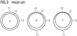
- Figure 3 illustrates how the generators 10 in present systems are assembled with a substantially concentric nominal airgap 13 (A). Once assembled with the wind rotor 5 in idling state the rotor 11 tilts slightly relative to the stator 12 due to gravity, the rotor 11 thus 'forming' the reduced airgap 13'.
- the minimum reduced airgap 13' is expected to be at the upper part of the circumference of the stator 12.
- a further reduction of the reduced airgap 13' is expected due to wind loads (C).
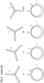
- Figure 4 illustrates the reduced airgap 13' under load at different wing 4 positions, 0°, 15°, 30°, 60°, where the angles of rotation are defined in a clockwise rotation relative to an upper wing 4, such that an upper blade 4 rotation of 0° corresponds to the blade 4 in azimuth position pointing straight upwards.
- the reduced airgap 13' under load is largest at 0° angle but is then continuously reduced at rotations until a rotation of 60° where one of the blades 4 are pointing straight downwards.
- FIG. 5A illustrates the solution according to the present invention, where the generator 10 is assembled with a concentric stator 12 relative to the rotor 13.
- the generator 10 in the illustrated embodiment solution is assembled such that without load or gravity the rotor 11 and stator is positioned eccentric relative to each other, the rotor 11 tilting positively relative to the gravity induced tilting, the negative direction of tilt.
- the stator 12 and rotor 12 thus is mounted non-concentric, or eccentric, or non-parallel to each other defined in the absence of gravity.
- a reduced airgap 13'' is formed at the lower part of the generator 10 below the stator 12 seen in the location of the defined plane P.
- Figure 5B illustrates an embodiment where the positive tilt is such that in idle state under no load, but under gravity of the hub/rotor 5 and blades 4, the stator 12 will be positioned substantially concentric with the rotor 11, corresponding to them extending essentially in parallel.
- Figure 5C illustrates the generator 10 under load where the reduced airgap 13' is formed at the upper part above the stator 12. Though there still is a reduced airgap 13', it is substantially smaller than when assembling concentrically as illustrated in fig. 3 .
- Figure 6 is a side view of the situation as illustrated in fig. 5A , where the generator 10 is assembled such that without load or gravity, the rotor 11 tilts positively relative to the gravity induced tilting.
- the rotor 11 and stator 12 thus extend non-parallel to each other.
- a reduced airgap 13" is formed at the lower part of the generator 10 below the stator 12 again seen in the plane P.
- Figure 7 is a flow chart illustrating the method of arranging the generator 10 within the nacelle 3 according to the present invention.
- the method being in a first step 100, to position a generator 10 within the nacelle 3 of a wind turbine.
- To 110 arrange the generator 10 within the nacelle 3 such that the rotor 11 tilts in the absence of gravity and load
Landscapes
- Engineering & Computer Science (AREA)
- Life Sciences & Earth Sciences (AREA)
- Sustainable Energy (AREA)
- Sustainable Development (AREA)
- Power Engineering (AREA)
- Chemical & Material Sciences (AREA)
- Combustion & Propulsion (AREA)
- Mechanical Engineering (AREA)
- General Engineering & Computer Science (AREA)
- Manufacturing & Machinery (AREA)
- Wind Motors (AREA)
Abstract
The invention relates to a wind turbine (1) comprising a nacelle (3) and a wind rotor (5) with blades (3), and where a generator (10) is positioned within the nacelle (3) comprising a rotor (11) connected to the wind rotor (5) and a stator (12), where the generator (10) is mounted such that the rotor (11) is positioned eccentric relative to the stator (12) in the absence of gravity and load.
The invention further relates to the method to install the generator accordingly.
Description
- The present invention relates to the protection of the generator in wind turbines bay ensuring a minimum air gap between rotor and stator despite heavy load.
- Generators, such as direct drive generators for wind turbines, operate with a relatively small airgap between the rotor and the stator. The rotor and the stator include permanent magnets, electromagnetic windings, combinations thereof, or other magnetic devices arranged to provide a magnetic flux across the airgap sufficient to generate electricity.
- It is desirable to have a small an airgap as the magnetic force is inversely related to the square of the distance between rotor and stator. Decreasing the size of the airgap increases the magnetizing current, which is the amount of current needed to drive the magnetic flux through the air gap. The greater the number of poles on the generator, the greater the number of times the flux must cross the air gap for each revolution.
- The weight of elements like the blades and the wind rotor itself is however substantial and tend to drag the elements downwards by gravity when mounted.
- The risk under substantial wind loads however is that the rotor and stator come in direct contact damaging the generator.
- The airgap therefore needs to be maintained at a sufficient size to avoid the risk of contact.
- The present invention relates to increase efficiency by allowing the introduction of a smaller airgap.
- The object of the invention is solved according to the features and methods indicated in the claims.
- This includes introducing a wind turbine comprising a nacelle and a wind rotor with blades, and where a generator comprising a rotor connected to the wind rotor and a stator is positioned within the nacelle, characterized in that, the generator is mounted such that the rotor tilts in the absence of gravity and load.
- The rotor may be mounted such that it in the absence of gravity and load it is positioned eccentric but is concentric under the presence of gravity but no load.
- The rotor may be mounted such that it in the absence of gravity and load tilts reversely (or positively) to the tilt induced by the presence of gravity.
- The rotor may be mounted such that it in the absence of gravity and load tilts reversely to the tilt induced by the presence of gravity, but in the presence of gravity, the rotor is substantially eccentric to the stator.
- The tilting of the rotor relative to the stator may be achieved by adjusting the segment during tightening by tilt-adjusting means.
- The tilting of the rotor relative to the stator may be ensured by machining a fixed shaft recess with eccentricity instead of concentricity.
- The present invention further relates to the method to mount a generator in the nacelle of a wind turbine, the generator comprising a rotor connected to a wind rotor with blades and a stator, and where the method includes for the generator to be positioned within the nacelle, such that the rotor tilts in the absence of gravity and load.
- The rotor may be mounted such that it in the absence of gravity and load it tilts reversely (or positively) to the tilt induced in the presence of gravity.
- The rotor may be mounted such that in the absence of gravity and load it tilts reversely (or positively) to the tilt induced by the presence of gravity, but in the presence of gravity the stator is substantially eccentric to the rotor.
- The tilting of the rotor relative to the stator may be achieved by adjusting the segment during tightening by tilt-adjusting means.
- The tilting of rotor relative to the stator may be ensured by machining a fixed shaft recess with eccentricity instead of concentricity.
-
- Figure 1
- shows a schematic presentation of a general wind turbine
- Figure 2A
- shows a schematic presentation of a generator with fixed stator and a rotor connected to a wind rotor.
- Figure 2B
- shows a schematic presentation the generator rotor tilting relative to the fixed stator under influence of gravity and load on the wind rotor.
- Figure 3
- shows a schematic presentation of the rotor within the generator when installed concentric as in prior installations, respectively also showing the effect of gravity and load
- Figure 4
- shows the effect of different azimuth angles of the blades to the eccentric installation of the rotor relative to the stator in prior installations.
- Figure 5
- shows a schematic presentation of the rotor within the generator when installed eccentric, respectively also showing the effect of gravity and load
- Figure 6
- shows a side view schematic presentation of the rotor within the generator when installed eccentric with higher air gap at the top.
- Figure 7
- shows a flow chart of the method of the present invention.
- The illustrations in the drawings are schematic. It is noted that in different figures, similar or identical elements are provided with the same reference signs.
-
Figure 1 shows anembodiment wind turbine 1 positioned in the water, such as the ocean. Thewind turbine 1 comprises atower 2 mounted on a non-depicted fundament. Anacelle 3 is arranged on top of thetower 2. Thewind turbine 1 further comprises awind rotor 5 having two, three or more blades 4 (in the perspective ofFigure 1 only twoblades 4 are visible). Thewind rotor 5 is rotatable around a longitudinal rotation axis Y. Thewind turbine 1 comprises an electric generator. -
Figure 2A illustrates agenerator 10 comprising arotor 11 connected to thewind rotor 5, and astator 12 fixedly positioned within thenacelle 3. Thewind turbine 1 in the illustrated embodiment is a direct drive wind turbine where thewind rotor 5 is directly connected to thegenerator 10, without any gearbox arranged in-between. The rotation of theblades 4 due to the wind is directly transmitted to thegenerator 10 via ashaft 6 connected to thewind rotor 5. When thewind turbine 10 is in operation, thegenerator 10 converts wind energy into electrical energy. - A
small airgap 13 exists between therotor 11 andstator 12. Therotor 11 and thestator 12 include permanent magnets, electromagnetic windings, combinations thereof, or other magnetic devices arranged to provide a magnetic flux across theairgap 13 sufficient to generate electricity. - The weight of elements like the
blades 4 and thewind rotor 5 itself is however substantial, and when mounted, the gravity tends to drag the elements downwards, as also illustrated infigure 2B . - In the illustration, the
stator 12 is substantially concentric relative to therotor 11, the two parts extending essentially in parallel. - It is desirable to have as small an
airgap 13 as the magnetic force is inversely related to the square of the distance betweenrotor 11 andstator 11. Decreasing the size of theairgap 13 increases the magnetizing current, which is the amount of current needed to drive the magnetic flux through the air gap. The greater the number of poles on the generator, the greater the number of times the flux must cross the air gap for each revolution. - However, having a small airgap 13 (possible in the order of millimeters or a few centimeters), this quickly forms a problem when the
rotor 11 tilts relative to the stator. This is also illustrated infigure 2B showing that theairgap 13 is changed as therotor 11 tilts slightly relative to thestator 12. - In the present context, and as illustrated in
fig. 2B , therotor 11 tilts negatively relative to thestator 12, where a negative tilt in the present is defined as the direction of tilt as is induced by of gravity. - This leads to a reduced airgap 13' which may be close to zero, or zero, such that the part touches.
- In the present the reduced airgap 13' is defined as being the
minimum airgap 13 in the circumference of thestator 12 seen in the plane P of the end phase of thestator 12 proximal to thewind rotor 5. -
Figure 3 illustrates how thegenerators 10 in present systems are assembled with a substantially concentric nominal airgap 13 (A). Once assembled with thewind rotor 5 in idling state therotor 11 tilts slightly relative to thestator 12 due to gravity, therotor 11 thus 'forming' the reduced airgap 13'. - According to the present defined location according to the plane P, the minimum reduced airgap 13' is expected to be at the upper part of the circumference of the
stator 12. - A further reduction of the reduced airgap 13' is expected due to wind loads (C).
-
Figure 4 illustrates the reduced airgap 13' under load atdifferent wing 4 positions, 0°, 15°, 30°, 60°, where the angles of rotation are defined in a clockwise rotation relative to anupper wing 4, such that anupper blade 4 rotation of 0° corresponds to theblade 4 in azimuth position pointing straight upwards. - As can be seen, the reduced airgap 13' under load is largest at 0° angle but is then continuously reduced at rotations until a rotation of 60° where one of the
blades 4 are pointing straight downwards. -
Figure 5A illustrates the solution according to the present invention, where thegenerator 10 is assembled with aconcentric stator 12 relative to therotor 13. Thegenerator 10 in the illustrated embodiment solution is assembled such that without load or gravity therotor 11 and stator is positioned eccentric relative to each other, therotor 11 tilting positively relative to the gravity induced tilting, the negative direction of tilt. Thestator 12 androtor 12 thus is mounted non-concentric, or eccentric, or non-parallel to each other defined in the absence of gravity. - In the illustration a reduced airgap 13'' is formed at the lower part of the
generator 10 below thestator 12 seen in the location of the defined plane P. -
Figure 5B illustrates an embodiment where the positive tilt is such that in idle state under no load, but under gravity of the hub/rotor 5 andblades 4, thestator 12 will be positioned substantially concentric with therotor 11, corresponding to them extending essentially in parallel. -
Figure 5C illustrates thegenerator 10 under load where the reduced airgap 13' is formed at the upper part above thestator 12. Though there still is a reduced airgap 13', it is substantially smaller than when assembling concentrically as illustrated infig. 3 . -
Figure 6 is a side view of the situation as illustrated infig. 5A , where thegenerator 10 is assembled such that without load or gravity, therotor 11 tilts positively relative to the gravity induced tilting. Therotor 11 andstator 12 thus extend non-parallel to each other. - In the illustration a reduced
airgap 13" is formed at the lower part of thegenerator 10 below thestator 12 again seen in the plane P. -
Figure 7 is a flow chart illustrating the method of arranging thegenerator 10 within thenacelle 3 according to the present invention. - The method being in a
first step 100, to position agenerator 10 within thenacelle 3 of a wind turbine. - To 110 arrange the
generator 10 within thenacelle 3 such that therotor 11 tilts in the absence of gravity and load
Claims (11)
- Wind turbine (1) comprising a nacelle (3) and a wind rotor (5) with blades (3), and where a generator (10) comprising a rotor (11) connected to the wind rotor (5) and a stator (12) is positioned within the nacelle (3), characterized in that, the generator (10) is mounted such that the rotor (11) is positioned eccentric relative to the stator (12) in the absence of gravity and load.
- Wind turbine (1) according to claim 1, wherein the rotor (11) is mounted such that it in the absence of gravity and load it is positioned eccentric but is concentric under the presence of gravity but no load.
- Wind turbine (1) according to claim 1, wherein the rotor (11) is mounted such that it in the absence of gravity and load the eccentricity is ensured by the rotor (11) tilting reversely to the tilt induced by the presence of gravity.
- Wind turbine (1) according to claim 1 or 3, wherein the rotor (11) is mounted such that it in the absence of gravity and load it tilts reversely to the tilt induced in the presence of gravity, but in the presence of gravity, the rotor (11) is substantially eccentric to the stator (12).
- Wind turbine (1) according to claim 1, 2, 3 or 4, wherein the eccentricity of rotor (11) relative to the stator 12 is achieved by adjusting the segment during tightening by eccentricity-adjusting means.
- Wind turbine (1) according to claim 1, 2, 3 or 4, wherein the eccentricity of the rotor (11) relative to the stator 12 is ensured by machining a fixed shaft recess with eccentricity instead of concentricity.
- Method to mount a generator (10) in the nacelle (3) of a wind turbine (1), the generator (10) comprising a rotor (11) connected to a wind rotor (5) with blades (4) and a stator (12), and where the method includes for the generator (10) to be positioned within the nacelle (3), such that the rotor (11) tilts in the absence of gravity and load.
- Method according to claim 7, wherein the rotor (11) is mounted such that it in the absence of gravity and load it tilts reversely to the tilt induced in the presence of gravity.
- Method according to claim 7 or 8, wherein the rotor (11) is mounted such that in the absence of gravity and load tilts reversely to the tilt induced by the presence of gravity, but in the presence of gravity the stator (12) is substantially eccentric to the rotor (11).
- Method according to claim 7, 8 or 9, wherein the tilting of rotor (11) relative to the stator 12 is achieved by adjusting the segment during tightening by tilt-adjusting means.
- Method according to claim 7, 8 or 9, wherein the tilting of rotor (11) relative to the stator 12 is ensured by machining a fixed shaft recess with eccentricity instead of concentricity.
Priority Applications (1)
| Application Number | Priority Date | Filing Date | Title |
|---|---|---|---|
| EP22207139.1A EP4368830A1 (en) | 2022-11-14 | 2022-11-14 | Generator for wind turbine |
Applications Claiming Priority (1)
| Application Number | Priority Date | Filing Date | Title |
|---|---|---|---|
| EP22207139.1A EP4368830A1 (en) | 2022-11-14 | 2022-11-14 | Generator for wind turbine |
Publications (1)
| Publication Number | Publication Date |
|---|---|
| EP4368830A1 true EP4368830A1 (en) | 2024-05-15 |
Family
ID=84331997
Family Applications (1)
| Application Number | Title | Priority Date | Filing Date |
|---|---|---|---|
| EP22207139.1A Withdrawn EP4368830A1 (en) | 2022-11-14 | 2022-11-14 | Generator for wind turbine |
Country Status (1)
| Country | Link |
|---|---|
| EP (1) | EP4368830A1 (en) |
Citations (2)
| Publication number | Priority date | Publication date | Assignee | Title |
|---|---|---|---|---|
| US20110133586A1 (en) * | 2009-12-08 | 2011-06-09 | Henrik Stiesdal | Arrangement to Compensate a Non-Uniform Air Gap of an Electric Machine |
| US20200096027A1 (en) * | 2016-12-19 | 2020-03-26 | Vestas Wind Systems A/S | Paired eccentric cam adjuster |
-
2022
- 2022-11-14 EP EP22207139.1A patent/EP4368830A1/en not_active Withdrawn
Patent Citations (2)
| Publication number | Priority date | Publication date | Assignee | Title |
|---|---|---|---|---|
| US20110133586A1 (en) * | 2009-12-08 | 2011-06-09 | Henrik Stiesdal | Arrangement to Compensate a Non-Uniform Air Gap of an Electric Machine |
| US20200096027A1 (en) * | 2016-12-19 | 2020-03-26 | Vestas Wind Systems A/S | Paired eccentric cam adjuster |
Similar Documents
| Publication | Publication Date | Title |
|---|---|---|
| US8860239B2 (en) | Wind or water energy installation | |
| US6975045B2 (en) | Wind power generating system | |
| US20110031756A1 (en) | Self-starting darrieus wind turbine | |
| EP2348619A1 (en) | Magnet assembly | |
| US20120049523A1 (en) | Wind jet turbine ii | |
| EP3771073B1 (en) | Electromagnetic modules of electrical machines | |
| EP2623774A2 (en) | Vertical shaft turbine and bidirectional stack type vertical shaft turbine provided with same | |
| EP1340910A1 (en) | Aerogenerator with axial flux permanent magnets and regulation thereof | |
| WO2010108196A1 (en) | Wind jet turbine ii | |
| EP2574774A1 (en) | Method to rotate the rotor of a wind turbine and means to use in this method | |
| US20090250938A1 (en) | Wind turbine incorporated in an electric transmission tower | |
| WO2011071841A2 (en) | Wind-driven electric power generation system adapted for mounting along the side of vertical, man-made structures such as large buildings | |
| WO2016148015A1 (en) | Turbine rotor and natural energy generating device equipped with same | |
| KR100935713B1 (en) | Wind power generator | |
| GB2500589A (en) | Pre-assembled wind turbine for offshore applications | |
| WO2016148016A1 (en) | Impeller and natural energy power generation device provided with same | |
| US20230003191A1 (en) | Wind turbine control | |
| WO2013063621A1 (en) | Generator | |
| EP3557052A1 (en) | Transformer support for a wind turbine | |
| EP4468569A1 (en) | Winding assemblies and related methods | |
| EP4369575A1 (en) | Generator for wind turbine | |
| EP4629485A1 (en) | Cooling of coils of electrical machines | |
| EP4534834A1 (en) | Horizontal-axis wind turbine | |
| WO2018146069A1 (en) | A vertical axis wind turbine, and method for operating such a wind turbine | |
| KR20130000468A (en) | A wind power generator with a auxiliary blade |
Legal Events
| Date | Code | Title | Description |
|---|---|---|---|
| PUAI | Public reference made under article 153(3) epc to a published international application that has entered the european phase |
Free format text: ORIGINAL CODE: 0009012 |
|
| STAA | Information on the status of an ep patent application or granted ep patent |
Free format text: STATUS: THE APPLICATION HAS BEEN PUBLISHED |
|
| AK | Designated contracting states |
Kind code of ref document: A1 Designated state(s): AL AT BE BG CH CY CZ DE DK EE ES FI FR GB GR HR HU IE IS IT LI LT LU LV MC ME MK MT NL NO PL PT RO RS SE SI SK SM TR |
|
| STAA | Information on the status of an ep patent application or granted ep patent |
Free format text: STATUS: THE APPLICATION IS DEEMED TO BE WITHDRAWN |
|
| 18D | Application deemed to be withdrawn |
Effective date: 20241116 |