EP4368760A1 - Laundry treatment device - Google Patents
Laundry treatment device Download PDFInfo
- Publication number
- EP4368760A1 EP4368760A1 EP21955722.0A EP21955722A EP4368760A1 EP 4368760 A1 EP4368760 A1 EP 4368760A1 EP 21955722 A EP21955722 A EP 21955722A EP 4368760 A1 EP4368760 A1 EP 4368760A1
- Authority
- EP
- European Patent Office
- Prior art keywords
- water storage
- water
- storage box
- front support
- laundry treatment
- Prior art date
- Legal status (The legal status is an assumption and is not a legal conclusion. Google has not performed a legal analysis and makes no representation as to the accuracy of the status listed.)
- Pending
Links
- XLYOFNOQVPJJNP-UHFFFAOYSA-N water Substances O XLYOFNOQVPJJNP-UHFFFAOYSA-N 0.000 claims abstract description 333
- 238000003860 storage Methods 0.000 claims abstract description 166
- 238000004891 communication Methods 0.000 claims abstract description 29
- 238000009413 insulation Methods 0.000 claims description 32
- 230000004308 accommodation Effects 0.000 claims description 27
- 238000003780 insertion Methods 0.000 claims description 14
- 230000037431 insertion Effects 0.000 claims description 14
- 238000003466 welding Methods 0.000 claims description 5
- 238000005086 pumping Methods 0.000 claims 1
- 230000000694 effects Effects 0.000 description 13
- 238000001035 drying Methods 0.000 description 8
- 230000008878 coupling Effects 0.000 description 5
- 238000010168 coupling process Methods 0.000 description 5
- 238000005859 coupling reaction Methods 0.000 description 5
- 238000001514 detection method Methods 0.000 description 5
- 230000008859 change Effects 0.000 description 4
- 239000000463 material Substances 0.000 description 4
- 230000001954 sterilising effect Effects 0.000 description 4
- 230000032683 aging Effects 0.000 description 3
- 238000004519 manufacturing process Methods 0.000 description 3
- 238000000222 aromatherapy Methods 0.000 description 2
- 230000000903 blocking effect Effects 0.000 description 2
- 238000009833 condensation Methods 0.000 description 2
- 230000005494 condensation Effects 0.000 description 2
- 230000005674 electromagnetic induction Effects 0.000 description 2
- 230000004907 flux Effects 0.000 description 2
- 230000017525 heat dissipation Effects 0.000 description 2
- 239000000203 mixture Substances 0.000 description 2
- 238000004904 shortening Methods 0.000 description 2
- 238000004659 sterilization and disinfection Methods 0.000 description 2
- 238000009423 ventilation Methods 0.000 description 2
- 238000005406 washing Methods 0.000 description 2
- 239000000853 adhesive Substances 0.000 description 1
- 230000001070 adhesive effect Effects 0.000 description 1
- 230000015572 biosynthetic process Effects 0.000 description 1
- 238000010586 diagram Methods 0.000 description 1
- 238000005516 engineering process Methods 0.000 description 1
- 239000011152 fibreglass Substances 0.000 description 1
- 238000010438 heat treatment Methods 0.000 description 1
- 238000009434 installation Methods 0.000 description 1
- 230000002452 interceptive effect Effects 0.000 description 1
- 238000012986 modification Methods 0.000 description 1
- 230000004048 modification Effects 0.000 description 1
- 238000004321 preservation Methods 0.000 description 1
- 230000009467 reduction Effects 0.000 description 1
- 238000007789 sealing Methods 0.000 description 1
- 238000005507 spraying Methods 0.000 description 1
- 239000008400 supply water Substances 0.000 description 1
Images



Classifications
-
- D—TEXTILES; PAPER
- D06—TREATMENT OF TEXTILES OR THE LIKE; LAUNDERING; FLEXIBLE MATERIALS NOT OTHERWISE PROVIDED FOR
- D06F—LAUNDERING, DRYING, IRONING, PRESSING OR FOLDING TEXTILE ARTICLES
- D06F39/00—Details of washing machines not specific to a single type of machines covered by groups D06F9/00 - D06F27/00
- D06F39/40—Steam generating arrangements
-
- D—TEXTILES; PAPER
- D06—TREATMENT OF TEXTILES OR THE LIKE; LAUNDERING; FLEXIBLE MATERIALS NOT OTHERWISE PROVIDED FOR
- D06F—LAUNDERING, DRYING, IRONING, PRESSING OR FOLDING TEXTILE ARTICLES
- D06F2103/00—Parameters monitored or detected for the control of domestic laundry washing machines, washer-dryers or laundry dryers
- D06F2103/60—Parameters monitored or detected for the control of domestic laundry washing machines, washer-dryers or laundry dryers related to auxiliary conditioning or finishing agents, e.g. filling level of perfume tanks
- D06F2103/62—Parameters monitored or detected for the control of domestic laundry washing machines, washer-dryers or laundry dryers related to auxiliary conditioning or finishing agents, e.g. filling level of perfume tanks related to systems for water or steam used for conditioning or finishing
-
- D—TEXTILES; PAPER
- D06—TREATMENT OF TEXTILES OR THE LIKE; LAUNDERING; FLEXIBLE MATERIALS NOT OTHERWISE PROVIDED FOR
- D06F—LAUNDERING, DRYING, IRONING, PRESSING OR FOLDING TEXTILE ARTICLES
- D06F25/00—Washing machines with receptacles, e.g. perforated, having a rotary movement, e.g. oscillatory movement, the receptacle serving both for washing and for centrifugally separating water from the laundry and having further drying means, e.g. using hot air
-
- D—TEXTILES; PAPER
- D06—TREATMENT OF TEXTILES OR THE LIKE; LAUNDERING; FLEXIBLE MATERIALS NOT OTHERWISE PROVIDED FOR
- D06F—LAUNDERING, DRYING, IRONING, PRESSING OR FOLDING TEXTILE ARTICLES
- D06F34/00—Details of control systems for washing machines, washer-dryers or laundry dryers
- D06F34/14—Arrangements for detecting or measuring specific parameters
-
- D—TEXTILES; PAPER
- D06—TREATMENT OF TEXTILES OR THE LIKE; LAUNDERING; FLEXIBLE MATERIALS NOT OTHERWISE PROVIDED FOR
- D06F—LAUNDERING, DRYING, IRONING, PRESSING OR FOLDING TEXTILE ARTICLES
- D06F37/00—Details specific to washing machines covered by groups D06F21/00 - D06F25/00
- D06F37/20—Mountings, e.g. resilient mountings, for the rotary receptacle, motor, tub or casing; Preventing or damping vibrations
- D06F37/22—Mountings, e.g. resilient mountings, for the rotary receptacle, motor, tub or casing; Preventing or damping vibrations in machines with a receptacle rotating or oscillating about a horizontal axis
-
- D—TEXTILES; PAPER
- D06—TREATMENT OF TEXTILES OR THE LIKE; LAUNDERING; FLEXIBLE MATERIALS NOT OTHERWISE PROVIDED FOR
- D06F—LAUNDERING, DRYING, IRONING, PRESSING OR FOLDING TEXTILE ARTICLES
- D06F39/00—Details of washing machines not specific to a single type of machines covered by groups D06F9/00 - D06F27/00
- D06F39/12—Casings; Tubs
Definitions
- the present disclosure relates to the field of laundry treatment technologies, and more particularly, to a laundry treatment device.
- a washing machine with a drying function is usually provided with a heating device configured to heat air to form hot air to be introduced into a laundry treatment chamber, while cooperating with a fan to allow the hot air to circulate to achieve the function of drying laundry.
- This structure has to be improved due to its big occupation space, inconvenient mounting, and a lot of noise during operation.
- the present disclosure aims to solve at least one of the technical problems in the related art. To this end, according to embodiments of the present disclosure, there is provided a laundry treatment device.
- the laundry treatment device has a simple structure, which is capable of achieving a better steam effect.
- a laundry treatment device comprises a front support, a steam generator, and a water storage box.
- the steam generator has a steam generation chamber.
- the water storage box has a water storage chamber in communication with the steam generation chamber.
- Each of the water storage box and the steam generator is disposed at the front support.
- the water storage box and the steam generator by providing the water storage box and the steam generator, high-temperature steam can be generated to be introduced into the laundry treatment device for drying and sterilizing laundry.
- the steam generator has a simple structure, is compact and easy to mount, and has low operating noise, and therefore user experience is good.
- Each of the water storage box and the steam generator is mounted at the front support, occupying less space of the laundry treatment device and shortening a pipeline distance of the steam generator to reduce heat loss.
- fitting and the communication between the steam generator and the water storage box are convenient, and the overall structure has high strength and good stability.
- the steam generator is disposed above the water storage box.
- the steam generator comprises a generator body and a heat insulation component.
- the generator body has a steam outlet.
- the heat insulation component defines an accommodation chamber in communication with an ambient environment. At least a part of the generator body is disposed in the accommodation chamber.
- the heat insulation component is adapted to be cooperatively connected to the front support.
- the front support has a mounting portion; and the heat insulation component has a connection portion.
- the connection portion and the mounting portion are in a corresponding position and are engaged with each other.
- the mounting portion is formed as a mounting post protruding from the front support; and the connection portion is formed as a connection hole.
- the mounting portion is fixedly connected to the connection portion by a fastener passing through the connection hole.
- the heat insulation component comprises a base, an upper cover, and a clamp member.
- the upper cover is disposed on the base.
- the accommodation chamber is defined between the upper cover and the base.
- the clamp member is disposed at an outer side of the upper cover and the base and tightly clamping and fixedly connecting the upper cover to the base.
- one of the water storage box and the front support has a slot; and the other one of the water storage box and the front support has an insertion portion.
- the insertion portion is inserted into and engaged with the slot.
- the front support has a support portion formed as a support table; the slot is disposed at the support table; and a part of the water storage box protrudes outwardly to form the insertion portion.
- the water storage box comprises a mounting plate. At least part of the mounting plate abuts against the front support, and the mounting plate is connected to the front support by a fastener.
- the water storage box comprises a first box and a second box.
- the first box has a water outlet in communication with the steam generator.
- the second box is disposed above the first box and sealingly engaged with the first box to define the water storage chamber.
- the second box has a water inlet. The second box is engaged with the first box through welding.
- the laundry treatment device further comprises a water level detector disposed in the water storage box and detecting a water level in the water storage chamber.
- the water level detector comprises a float ball and a magnetic member.
- the float ball is disposed in the water storage chamber.
- the magnetic member is disposed at an outer side of the water storage box. The float ball and the magnetic member cooperate with each other to detect the water level in the water storage chamber.
- the front support has a water replenishment opening.
- the water replenishment opening is in communication with the water inlet of the water storage box and located at higher level than the water inlet.
- the front support has a laundry input opening in communication with the water replenishment opening.
- the laundry treatment device further comprises an air inflowing grille movably disposed at the front support.
- the air inflowing grille has the water replenishment opening and a water replenishment chamber.
- the water storage box is connected to the replenishment chamber through a connection pipe.
- the laundry treatment device further comprises a water pump disposed at the front support and adapted to pump water from the water storage chamber into the generator body.
- the laundry treatment device further comprises a steam nozzle disposed at the front support and adjacent to the steam generator.
- the steam nozzle is adapted to be in communication with the steam generation chamber.
- the terms “mounted”, “connected”, “coupled”, and “fixed” are understood broadly, such as fixed, detachable mountings, connections, and couplings or integrated, and can be mechanical or electrical mountings, connections, and couplings, and also can be direct and via media indirect mountings, connections, and couplings, and further can be inner mountings, connections and couplings of two components, which can be understood by those skilled in the art according to the detail embodiment of the present disclosure.
- the laundry treatment device herein may be a dryer, a washing machine, a washer-dryer, etc.
- the laundry treatment device comprises a front support 20 disposed at a front part of the laundry treatment device.
- the laundry treatment device further comprises a steam generator 10 having a steam generation chamber.
- the steam generator 10 is disposed at the front support 20. Steam generated by the steam generator 10 is introduced into a laundry treatment chamber to allow for steam drying and steam sterilization of laundry in the laundry treatment chamber.
- providing the steam generator 10 at the front support 20 can shorten a pipeline distance of the steam to be introduced into the laundry treatment chamber and can avoid condensation of the steam into water in the pipeline. In this way, heat loss is reduced with an increased efficiency of drying the laundry.
- the laundry treatment device further comprises a water storage box 30 having a water storage chamber in communication with the steam generation chamber, and the water storage box 30 is configured to supply water to the steam generator 10.
- the water can be supplied to the steam generation chamber in real time during operation of the steam generator 10, which realizes uninterrupted operation of the steam generator 10 to provide a sufficient steam volume, and thus to improve a drying effect, a sterilization effect, etc., of the laundry.
- the water storage box 30 is disposed at the front support 20, which is easy to mount and may be integrated to be mounted at a housing of the laundry treatment device, and stability of a fitting structure is good. At the same time, it is convenient to replenish water to the water storage box 30 through the front support 20, which is convenient to operate.
- the water storage box 30 and the steam generator 10 in the laundry treatment device according to the embodiments of the present disclosure, high-temperature steam may be generated to be introduced into the laundry treatment device for drying and sterilizing laundry.
- the steam generator 10 has the simple structure, is compact and easy to mount, and has low operating noise, and therefore user experience is good.
- Each of the water storage box 30 and the steam generator 10 is mounted at the front support 20, occupying less space of the laundry treatment device and shortening the pipeline distance of the steam generator 10 to reduce the heat loss.
- fitting and the communication between the steam generator 10 and the water storage box 30 are convenient, and the overall structure has high strength and good stability.
- the steam generator 10 is disposed above the water storage box 30, and the steam generator 10 may be disposed at an upper part of the front support 20.
- the upper part of the front support 20 herein is an upper part relative to a middle position of the front support 20, which does not extend beyond an upper edge of the front support 20. Since the steam generator 10 is disposed at the higher position and may be adjacent to a vent opening 27 of the front support 20, a distance between the steam generator 10 and the vent opening 27 is reduced, which avoids the condensation of the steam into water in the pipeline to reducing the heat loss.
- the water storage box 30 is disposed at a lower part of the front support 20.
- the lower part of the front support 20 herein is a lower part relative to a middle position of the front support 20, which does not extend beyond a lower edge of the front support 20. Since the water storage box 30 is disposed at the lower position, it is more convenient for a user to feed water to the water storage box 30 to improve ease of operation. Water in the water storage box 30 can be pumped into the steam generation chamber of the steam generator 10 by the water pump 40. An overall layout is reasonable.
- the steam generator 10 comprises a generator body 11 and a heat insulation component 12.
- the generator body 11 has the steam generation chamber, and the generator body 11 may generate high-temperature steam and has a steam outlet 111.
- the heat insulation component 12 defines an accommodation chamber, and the accommodation chamber may be in communication with an ambient environment. Therefore, a part of the generator body 11 is disposed in the accommodation chamber. That is, the heat insulation component 12 is disposed at an outer side of the generator body 11.
- the heat insulation component 12 may have an insulation effect on the generator body 11 to prevent heat dissipation of the steam.
- the heat insulation component 12 may prevent direct emanation of the heat of the generator body 11 to structural members around the steam generator that leads to deformation, aging, etc., of the various structural members under a high temperature, and affects service life of the various structural members.
- the heat insulation component 12 may be cooperatively connected with the front support 20 to realize the installation of the steam generator 10 on the front support 20.
- the heat insulation component 12 has a connection portion
- the front support 20 has a mounting portion 22
- the heat insulation component 12 has the connection portion
- the connection portion and the mounting portion 22 are in corresponding positions.
- the steam generator 10 is mounted and fixed through the mutual cooperation between the connection portion and the mounting portion 22.
- the connection portion may be an insertion block
- the mounting portion 22 is a slot
- the connection portion is inserted into and engaged with the mounting portion.
- the connection portion may also be a connection hole
- the mounting portion 22 has a corresponding hole
- the steam generator 10 is fixedly connected to the front support 20 by a fastener.
- the connection portion and the mounting portion 22 may also be connected to each other in a snap-fit manner. In this way, the mounting is more convenient and fitting efficiency is improved.
- connection portion is disposed at the heat insulation member 12, and therefore no additional fitting structure needs to be provided on the generator body 11, and the generator body 11 only needs to be mounted in the accommodation chamber of the heat insulation member 12. In this way, manufacture and fitting are convenient.
- the mounting portion 22 is formed as a mounting post protruding from the front support 20, a center of the mounting post has a mounting hole, the connection portion is formed as a connection hole, and the steam generator 10 is fixedly connected to the mounting post by a fastener passing through the connection hole and the mounting hole of the positioning post.
- a plurality of connection portion can be provided, and a corresponding plurality of the positioning post is provided.
- the connection portion comprises a first connection portion 13 and a second connection portion 14, and the first connection portion 13 and the second connection portion 14 may be disposed at opposite sides of the steam generator 10 respectively.
- a better fixing effect of the steam generator 10 is achieved.
- a plurality of first connection portion 13 can also be provided, and a plurality of second connection portion 14 can also be provided, to further improve fixing stability of the steam generator 10, and to prevent the steam generator 10 from rotating, shaking, etc.
- a plurality of support ribs can surround the mounting post to improve stability of the mounting post, and thus to improve mounting reliability of the steam generator 10.
- the heat insulation component 12 comprises a base 121 and an upper cover 122.
- the upper cover 122 is provided on the base 121, the accommodation chamber is defined between the upper cover 122 and the base 121, and the upper cover 122 is detachably connected to the base 121. Therefore, the generator body 11 is easily placed in the accommodation chamber.
- the base 121 can be directly engaged with and fixed to the upper cover 122, for example, by a snap hook and a snap groove to be engaged and fixed, or by a fastener to be fixedly connected, or by other structural members to be engaged and connected.
- the heat insulation component 12 further comprises a clamp member 123.
- the clamp member 123 is disposed at an outer side of the upper cover 122 and the base 121 and configured to tightly clamp and fixedly connect the upper cover 122 and the base 121. That is, under a condition that the upper cover 122 is engaged with the base 121 in place, the upper cover 122 is fixedly connected to the base 121 by wrapping the outer side of the upper cover 122 and the base 121 through the clamp member 123, eliminating a need to provide a fixing structure on the upper cover 122 and the base 121. In this way, the structure of the upper cover 122 and the base 121 is simplified while having the reliable connection and good structural stability.
- the water storage box 30 has a slot 23, and the front support 20 has an insertion portion 301, and mounting of the water storage box 30 is realized by the insertion portion 301 being inserted into and engaged with the slot 23. In this way, the mounting is convenient.
- the front support 20 has the slot 23, and the water storage box 30 has the insertion portion 301.
- a side of the front support 20 has a support portion 24, and the slot 23 is provided on the support portion 24. Therefore, stability of the slot 23 can be improved.
- stability and reliability of the mounting of the water storage box 30 are improved.
- a part of the water storage box 30 protrudes outwardly to form the insertion portion 301. That is, an outer wall surface of the part of the water storage box 30 is directly inserted into and engaged with the slot 23. In this way, the engagement is convenient and reliable, eliminating a need to provide other engagement structures at the water storage box 30, simplifying manufacturing process.
- the water storage box 30 is supported on the support portion 24, which is stable and prevents the water storage box 30 from shaking, etc.
- the support portion 24 herein may be a support rib.
- the support rib has a simple structure, and is easy to be integrally molded with the front support 20.
- the support portion 24 may also be a support table.
- the support table can not only increase an engagement contact surface area to improve the stability, but also can increase the structural strength at the slot 23 to further improve the fitting stability of the water storage box 30.
- the water storage box 30 comprises a mounting plate 33.
- the mounting plate 33 and a second box 32 of the water storage box 30 are fixedly connected to each other or are integrally molded.
- a part of the mounting plate 33 may abut against the front support 20 when the water storage box 30 is fitted with the front support 20, which realizes a type of positioning function and can improve the stability of the water storage box 30.
- the mounting plate 33 may also be connected to the front support 20 through the fastener, and therefore the water storage box 30 is firmly fixed to the front support 20.
- the water storage box 30 comprises a first box 31 and a second box 32.
- the second box 32 is disposed above the first box 31 and sealingly engaged with the first box 31 to define the water storage chamber, which can be sealed by a seal member or by a seal adhesive to avoid water leakage at the connection.
- the second box 32 may also be engaged with the first box 31 through welding, which is easy to operate and has high reliability of sealing.
- the second box 32 has a water inlet 302, and the first box 31 has a water outlet 303.
- the water inlet 302 and the water outlet 303 are in communication with the water storage chamber, and the water outlet 303 is in communication with the steam generator 10. Therefore, water in the water storage chamber can be introduced into the steam generation chamber. Furthermore, since the water inlet 302 is located at an upper part and the water outlet 303 is located at a lower part, the water in the water storage chamber can be easily emptied out and can circulate and flow to avoid residue of stagnant water, etc.
- the water storage box 30 further comprises a water level detector.
- the water level detector may be disposed in the water storage chamber or outside the water storage chamber.
- the water level detector is an infrared sensor, which detects a water volume in the water storage chamber by an infrared means.
- the water level detector comprises a float ball 35 and a magnetic member 37.
- the float ball 35 is disposed in the water storage chamber
- the magnetic member 37 is disposed at an outer side of the water storage box 30, and the outer side of the water storage box 30 is further provided with a closed loop formed by wires.
- the float ball 35 and the magnetic member 37 cooperate with each other, and it can be understood that the float ball 35 is provided with a magnet, and using the principle of electromagnetic induction, the float ball 35 moves and is away from the magnetic member 27 to allow magnetic flux to change and a current of the closed loop to change.
- a distance between the float ball 35 and the magnetic member 27 gradually becomes larger. When a certain distance is reached, i.e., when the water level reaches a predetermined level, an alarm is prompted, etc., to realize a detection of the water level in the water storage chamber.
- the water storage chamber is provided with a limit post 34.
- An upper end of the limit post 34 is connected to the second box 32.
- the float ball 35 may be sleeved on the limit post 34 and may move in a direction of the limit post 34, and the float ball 35 is slidingly engaged with the limit post 34.
- a top of the second box 32 is provided with a limit slot 36, and the magnetic member 37 is adapted to be inserted into the limit slot 36 to realize fixing of the magnetic member 37, which is simple in structure and convenient in mounting.
- the front support 20 has a water replenishment opening 304, the water replenishment opening 304 is in communication with the water inlet 302 of the water storage box 30, and the water replenishment opening 304 is located at higher level than the water inlet 302.
- a user can feed water into the water storage box 30 through the water replenishment opening 304, and the water replenishment opening 304 is provided at an opening 21 of the front support 20 to facilitate an operation of the user; and since the water replenishment opening 304 is located at higher level than the water inlet 302, information about full water feeding can be obtained when water overflows from the replenishment opening 304, preventing excessive water in the water storage box from overflowing into an interior of the laundry treatment device, and preventing affecting normal use of other structural members.
- the front support 20 has the opening 21 provided at the middle part of the front support 20, the opening 21 is in communication with the laundry treatment chamber of the laundry treatment device, and the user can put the laundry into the laundry treatment chamber through the opening 21.
- the water replenishment opening 304 is in communication with the opening 21, that is, the user can replenish water to the water storage box 30 through the water replenishment opening 304 when the opening 21 is opened, and the water replenishment opening 304 is covered when the opening 21 is closed. In this way, the water replenishment opening 304 is not exposed, which is aesthetically pleasing and can avoid being contaminated.
- the laundry treatment device further comprises an air inflowing grille 50 movably disposed at the front support 20.
- the air inflowing grille 50 can realize a ventilation effect while preventing the laundry from being rolled into the air duct.
- a part of an end portion of the air inflowing grille 50 is recessed downwardly to form a replenishment chamber, and the replenishment chamber has a replenishment opening 304 provided at a bottom wall of the replenishment chamber.
- the replenishment opening 304 is connected to the water storage box 30 through a connection pipe 60, and the water storage box 30 is connected to the water storage box 30 through the connection pipe 60.
- water can be replenished to the water storage box 30 through the water replenishment chamber, and when the water in the water replenishment chamber is no longer flowing to the water storage box 30, information about the full water feeding into the water storage box 30 is obtained, preventing the excessive water in the water storage box 30 from overflowing into the interior of the laundry treatment device.
- the water in the water replenishment chamber is temporarily stored in the water replenishment chamber, and the water in the water storage chamber automatically flows to the water storage chamber after flowing to the steam generation chamber, to avoid the overflowing of the water through the water replenishment opening 304 that affects the user's usage effect.
- the position of the water replenishment opening 304 is relatively concealed without affecting an appearance of the air inflowing grille 50, and effectively utilizes an occupied space of the air inflowing grille 50 to improve a space utilization rate.
- a cover is provided at the water replenishment port 304, and the cover is opened to pour water before steam is required.
- the laundry treatment device further comprises a water pump 40 disposed at the front support 20 and connected between the water outlet 303 and the steam generator 10.
- the steam generator 10 is disposed at the upper part of the front support 20 to facilitate proximity of the steam generator 10 to the vent opening 27 disposed at the upper portion of the front support 20.
- the water storage box 30 is disposed at the lower part of the front support 20, the water outlet 303 of the water storage box 30 is connected to a water inlet end of the water pump 40 through the connection pipe 60, and a water outlet end of the water pump 40 is connected to the steam generator 10 through the connection pipe 60. Therefore, the water pump 40 can pump the water from the water storage box 30 into the steam generator 10. Since the water pump 40 is also disposed at the front support 20, the cooperative connection of the water pump 40 to the water storage box 30 and the steam generator 10 is facilitated.
- a steam nozzle 26 disposed at the upper portion of the front support 20 is provided.
- the steam nozzle 26 is adjacent to the steam generator 10 and adapted to be in communication with the steam generation chamber.
- the steam nozzle 26 defines the vent opening 27 and is fixed to the front support 20 through the fastener, and the steam generator 20 may be connected to the steam nozzle 26 through the connection pipe 60. Therefore, the steam can be introduced to the vent opening 27 and be introduced into the laundry treatment chamber through the vent opening 27.
- the vent opening 27 may comprise a plurality of small holes to achieve a spraying effect. Thus, the steam can be uniformly sprayed onto the laundry in the laundry treatment chamber.
- a laundry treatment device according to embodiments of the present disclosure is described below with reference to FIGS. 1 to 10 .
- the laundry treatment device comprises a laundry treatment tub, a front support 20, a steam generator 10, a water storage box 30, and a water pump 40.
- the laundry treatment tub defines a laundry treatment chamber.
- the front support 20 is disposed at a front part of the laundry treatment device.
- a middle part of the front support 20 has an opening 21 in communication with the laundry treatment chamber.
- An air inflowing grille 50 is disposed at the front support 20, which not only can realize a ventilation effect but also can prevent the laundry from being rolled into an air duct of the front support 20.
- a part of an end of the air inflowing grille 50 is recessed downwardly to form a water replenishment chamber, and the replenishment chamber has a water replenishment opening 304 provided at a bottom wall of the water replenishment chamber.
- the water replenishment opening 304 is connected to the water storage box 30 through the connection pipe 60, and the position of the water replenishment opening 304 is relatively concealed without affecting the appearance of the air inflowing grille 50 and effectively utilizes the occupied space of the air inflowing grille 50 to improve the space utilization rate.
- the water replenishment chamber is provided with a cover detachably disposed at the air inflowing grille 50 and configured to open and close an opening of the water replenishment chamber, and foreign matter can be prevented from blocking the water replenishment opening 304 by providing the cover.
- a part of another end of the air inflowing grille 50 is recessed downwardly to form an accommodation recess configured to accommodate the aromatherapy, and the accommodation recess has an emanation hole disposed at a bottom wall of the accommodation recess and/or a side wall of the accommodation recess to facilitate emanation of the aromatherapy.
- a steam nozzle 26 disposed at an upper part of the front support 20 is provided.
- the steam nozzle 26 defines a vent opening 27 in communication with the opening 21.
- the front support 20 further has a mounting portion 22.
- the mounting portion 22 is formed as a mounting post protruding from the front support 20.
- a center of the mounting post has a mounting hole, and a plurality of support ribs can surround the mounting post to improve stability of the mounting post.
- the front support 20 comprises a support plate at a front side of the laundry treatment chamber. It can be understood that the support plate herein extends in a left-right direction and an up-down direction, and the support plate is further provided with a structural member such as a protruding rib protruding from a rear side surface of the support plate to increase structural strength and to facilitate a fitting with other structural members.
- the opening 21 is located at a middle part of the support plate, and the air inflowing grille 50 is mounted below the opening 21. The air inflowing grille 50 cooperates with the support plate, and the steam generator 10 and the water storage box 30 are disposed at the support plate.
- the steam generator 10 and the water storage box 30 are fixedly mounted at a rear side of the support plate, and each of the water storage box 30 and the steam generator 10 is disposed at a left side of the air inflowing grille 50, or, each of the water storage box 30 and the steam generator 10 may also be disposed at a right side of the air inflowing grille 50.
- the water storage box 30 can be cooperatively connected to the steam generator 10 through a connection pipe 60 at a side of the air inflowing grille 50 for easy connection.
- the water storage box 30 and the steam generator 10 are disposed at opposite sides of the air inflowing grille 50.
- the steam generator 10 is disposed at the front support 20 and located at the upper part of the front support 20. It can be understood that the upper part of the front support 20 herein is an upper part relative to a middle position of the front support 20, which does not extend beyond an upper edge of the front support 20, to improve reasonableness and compactness of an overall structural layout, and the steam generator 10 is adjacent to the steam nozzle 26 and connected to the steam nozzle 26 through the connection pipe 60.
- the steam generator 10 comprises a generator body 11 and a heat insulation component 12.
- the generator body 11 has an end having a water inlet and another end having a steam outlet 111.
- the generator body 11 is further provided with a connection terminal to facilitate a connection of the generator body 11 to a control circuit.
- the heat insulation component 12 defines an accommodation chamber, and the accommodation chamber is in communication with an ambient environment. Therefore, a part of the generator body 11 is disposed in an accommodation chamber, and the steam outlet 111 of the generator body 11 can protrude from the accommodation chamber to facilitate a connection of the steam outlet 111 to a vent opening 27.
- the heat insulation component 12 By disposing the heat insulation component 12 at an outer side of the generator body 11, on the one hand, the heat insulation component 12 can have an insulation effect on the generator body 11 to prevent heat dissipation of the steam, on the other hand, the heat insulation component 12 can prevent direct emanation of the heat of the generator body 11 to structural members around the steam generator that leads to deformation, aging, etc., of the various structural members under a high temperature, and affects service life of the various structural members.
- the heat insulation component 12 comprises a base 121, an upper cover 122, and a clamp member 123.
- the upper cover 122 is disposed on the base 121, the accommodation chamber is defined between the upper cover 122 and the base 121, and the upper cover 122 is detachably connected to the base 121. Therefore, the generator body 11 is easily placed in the accommodation chamber.
- the upper cover 122 and the base 121 are made of a high-temperature resistant material member, for example, a fiberglass mixture, which is chemically inert in many cases, has high strength, good stability, a high safety factor, lightweight, high-temperature resistance, and lower cost, and is easy to promote and use.
- the clamp member 123 can also be made of a high-temperature resistant material member to improve an effect of heat insulation and heat preservation of the overall structure.
- the clamp member 123 can also adopt a metallic member, which has high structural strength and can tightly clamp and fixedly connect the upper cover 122 and the base 121.
- the base 121 has a notch formed at a left side and a right side of the base 121, and the accommodation chamber can be connected to the ambient environment by the notch.
- the generator body 11 has an end having a water inlet joint and a line joint, and another end having an air outflowing joint.
- the water inlet joint, the line joint, and the air outflowing joint can protrude from the accommodation chamber through the notch to facilitate a connection of water inlet joint, the line joint, and the air outflowing joint to the ambient environment.
- the base 121 is further provided with a support rib protruding from an inner wall surface of the base 121.
- the support rib can serve a function in positioning, limiting, and supporting, to improve stability of the generator body 11.
- the accommodation chamber has a shape substantially same as a structure of the generator body 11 to avoid interference, shaking, etc., of the generator body 11 in the accommodation chamber, which affects performance and service life of the generator body 11.
- the upper cover 122 has a size larger than a size of the base 121. As illustrated in FIG. 9 , the upper cover 122 has an end that can extend above the water inlet joint and the line joint and thus can provide protection to the joints to prevent damage to the joints caused by collision, water ingress of the line joint, etc., that affect normal use of the joints.
- the upper cover 122 has another end that can extend to the air outflowing joint to further protect the air outflowing joint.
- the base 121 is provided with a limit portion 1212 at a side of the base 121 facing towards the upper cover 122, and the limit portion 1212 is formed as a limit rib protruding from an upper surface of the base 121; and the upper cover 122 is provided with an engagement portion (not illustrated in the FIG. 9 ) at a side of the upper cover 122 facing towards the base 121, and the engagement portion is formed as an engagement groove.
- the engagement groove has a shape corresponding to a shape of the limit rib, and the limit portion 1212 can be engaged with the engagement portion.
- the limit rib can be an elongated rib. Two limit ribs are provided and are symmetrically arranged in a width direction of the base 121, and each of the two limit ribs extends in a length direction of the base 121.
- Providing the limit portion 1212 and the engagement portion can serve a function in positioning and limiting the fitting of the upper cover 122 and the base 121, which facilitates locking of the upper cover 122 and the base 121 while preventing the connection between the upper cover 122 and the base 121 from shaking and interfering with the generator body 11, etc.
- the upper cover 122 is engaged with the base 121 in place to facilitate the mounting of the clamp member 123, which is convenient for positioning and mounting and has good engagement reliability.
- the clamp member 123 is disposed at an outer side of the upper cover 122 and the base 121 and configured to tightly clamp and fixedly connect the upper cover 122 and the base 121.
- the clamp member 123 comprises a clamp section 1231, a first fixing section 1232, a second fixing section 1233, and a third fixing section 1234.
- the clamp section 1231 is substantially formed into an annular shape with an opening and surrounds the outer side of the upper cover 122 and the base 121.
- the upper cover 122 has a first recessed portion 1221 at an outer surface of the upper cover 122
- the base 121 has a second recessed portion 1211 at an outer surface of the base 121
- the second recessed portion 1211 and the first recessed portion 1221 are in corresponding positions.
- a part of the clamp section 1231 is engaged with the first recessed portion 1221
- another part of the clamp section 1231 is engaged with the second recessed portion 1211.
- the first recessed portion 1221 extends along the outer surface of the upper cover 122 to form a half-annular shape
- the second recessed portion 1211 extends along the outer surface of the base 121 to form a half-annular shape.
- the first recessed portion 1221 cooperates with the second recessed portion 1211 to form an annular-shaped recess, and the clamp section 1231 can be mounted in the annular-shaped recess formed by the two recessed portions and realizes an insertion-type of engagement mounting, thereby preventing detachment of the clamp section 1231 from the upper cover 122 and the base 121, avoiding a fixing failure, and improving the stability of the overall structure.
- the first fixing section 1232 is disposed at an end of the clamp section 1231, and the second fixing section 1233 is disposed at another end of the clamp section 1231.
- the first fixing section 1232 has a first fixing hole 15, and the second fixing section 1233 has a second fixing hole.
- the second fixing hole and the first fixing hole 15 are in corresponding positions, and the first fixing section 1232 is fixedly connected to the second fixing section 1233 by the fastener passing through the first fixing hole 15 and the second fixing hole.
- the clamp section 1231 can be closely attached to the upper cover 122 and the base 121, and the upper cover 122 and the base 121 can be fixed through the clamp member 123.
- the fastener herein may be a bolt, which is easy to connect and has good stability.
- the first fixing section 1232 and the second fixing section 1233 are located at the upper part of the generator body 11, a first connection portion 13 is disposed at the first fixing section 1232, the third fixing section 1234 can be located at the lower part of the generator body 11, and a second connection portion 14 is disposed at the third fixing section 1234. That is, the first fixing section 1232 and the second fixing section 1233 are located at a first side of the generator body 11, and the third fixing section 1234 is located at a side of the generator body 11 opposite to the first side of the generator body 11, and each of the first connection portion 13 and the second connection portion 14 is formed as a connection hole, and the steam generator 10 is fixed to the front support 20 by the fasteners passing through the connection hole and the mounting hole of the positioning post. Fixed mounting by means of the connection portions on the two sides can improve the fixing effect of the steam generator 10 with good stability.
- the water storage box 30 comprises a first box 31 and a second box 32.
- the second box 32 is disposed above the first box 31 and engaged with the first box 31 through welding to define a water storage chamber. Water leakage is avoided at the connection through the welding.
- the second box 32 has a water inlet 302, and the first box 31 has a water outlet 303.
- the water inlet 302 and the water outlet 303 are in communication with the water storage chamber.
- the water inlet 302 is located at an upper part, and the water outlet 303 is located at a lower part, and therefore the water in the water storage chamber can be easily emptied out and can circulate and flow to avoid residue of stagnant water, etc.
- the water storage box 30 is disposed at the front support 20 and located at a lower part of the front support 20.
- the lower part of the front support 20 herein is a lower part relative to a middle position of the front support 20, which does not extend beyond a lower edge of the front support 20, to improve the reasonableness and compactness of the overall structural layout.
- the front support 20 has a slot 23, the water storage box 30 is provided with an insertion portion 301.
- the front support 20 has a support portion 24 at a side of the front support 20.
- the support portion 24 can be a support table or a support rib, and the slot 23 is disposed at the support portion 24. Therefore, the stability of the slot 23 can be improved.
- a part of the water storage box 30 protrudes outwardly to form the insertion portion 301. That is, an outer wall surface of the part of the water storage box 30 is directly inserted into and engaged with the slot 23. In this way, the engagement is convenient and reliable, eliminating a need to provide other engagement structures at the water storage box 30, simplifying manufacturing process.
- the water storage box 30 is supported on the support portion 24, which is stable and prevents the water storage box 30 from shaking, etc. Meanwhile, a space feature of the front support 20 is fully utilized to improve the stability of the structure.
- Two slots 23 are arranged opposite to each other, and two corresponding support portions 24 are provided. Each of the two slots 23 is supported on the corresponding support portion 24.
- the two support portions 24 can have the same structures, for example, each of the two slots 23 is supported on the support table, or each of the two slots 23 is supported on the support rib. As illustrated in FIG. 7 , in some examples, the two support portions 24 can also have different structures. One of the two slots 23 is supported on the support table, and the other of the two slots 23 is supported on the support rib.
- a mounting chamber 25 is defined between the two support portions 24, and a part of the water storage box 30 is mounted in the mounting chamber 25.
- the part of the water storage box 30 can be inserted into the mounting chamber 25, which can realize full utilization of the space of the front support 20 and increase a water storage volume of the water storage box 30. Furthermore, a part of the water storage box 30 is disposed at a middle of the two slots 23, and the mounting chamber 25 has a size matching a size of this part of the water storage box 30, which can increase the stability of the structure to avoid the shaking of the water storage box 30.
- the water storage box 30 has a mounting plate 33. As illustrated in FIGS. 3 , 7 , and 10 , the mounting plate 33 extends in a left-right direction and has a connection hole formed thereon, the front support 20 has a mounting post having a mounting hole, and the mounting plate 33 has a bent section extending rearwardly at a right edge of the mounting plate 33. The bent section abuts against a part of the front support 20 when the water storage box 30 is inserted into the slot 23.
- the mounting plate 33 is fixedly connected to the front support 20 by the fastener passing through the connection hole and the mounting post. Therefore, the water storage box 30 is firmly fixed to the front support 20.
- the water storage box 30 is located at a lower part of the front support 20, and the water storage box 30 is connected to a replenishment chamber through a connection pipe 60. Therefore, water can be fed into the water storage box 30 through a replenishment opening 304.
- the water replenishment opening 304 is in communication with the water inlet 302 of the water storage box 30, and the water inlet 302 is located at higher level than the water replenishment chamber.
- a user can feed water into the water storage box 30 through the water replenishment opening 304, and the water replenishment opening 304 is provided at an opening 21 of the front support 20 to facilitate an operation of the user that information about full water feeding can be obtained when water overflows from the replenishment opening 304, preventing excessive water in the water storage box from into an interior of the laundry treatment device, and preventing affecting normal use of other structural members; and the water replenishment opening 304 is located at a lower part of the laundry treatment device and is located at a lower part of the opening 21 configured to put the laundry, and therefore the user can conveniently perform a water replenishment operation even when the laundry treatment device is placed in a higher position.
- the water storage box 30 further comprises a water level detector.
- the water level detector can be disposed in the water storage chamber or outside of the water storage chamber.
- the water level detector is an infrared sensor, which detects a water volume in the water storage chamber by an infrared means.
- the water level detection device comprises a float ball 35 and a magnetic member 37.
- the float ball 35 is disposed in the water storage chamber, and the magnetic member 37 is disposed at an outer side of the water storage box 30.
- the water storage chamber is provided with a limit post 34.
- the limit post 34 can be integrally molded at the second box 32 or can be engaged with and connected to the second box 32 to allow an upper end of the limit post 34 to be connected to the second box 32.
- the float ball 35 can be sleeved on the limit post 34 and can move in a direction of the limit post 34, and the float ball 35 is slidingly engaged with the limit post 34.
- a top of the second box 32 is provided with a limit slot 36.
- the magnetic member 37 is adapted to be inserted into the limit slot 36 to realize fixing of the magnetic member 37.
- the outer side of the water storage box 30 is further provided with a closed loop formed by wires.
- the float ball 35 and the magnetic member 37 cooperate with each other, the float ball 35 is provided with a magnet, and using the principle of electromagnetic induction, the float ball 35 moves and is away from the magnetic member 27 to allow magnetic flux to change and a current of the closed loop to change.
- a distance between the float ball 35 and the magnetic member 27 gradually becomes larger. When a certain distance is reached, i.e., when the water level reaches a predetermined level, an alarm is prompted, etc., to realize a detection of the water level in the water storage chamber.
- the water storage box 30 further has a vent hole 305.
- the vent hole 305 is provided at the top of the second box 32 and configured to connect the water storage chamber to the ambient environment. It can be ensured that the water storage chamber is always connected to the ambient environment by providing the vent hole 305, avoiding formation of a negative pressure state in the water storage chamber, which affects outflowing of water.
- By providing the vent hole 305 at the top of the second box 32 automatic outflowing or overflowing of the water in the water storage chamber can be avoided.
- a part of an upper surface of the second box 32 protrudes upwardly to form a protrusion
- the vent hole 305 is provided at a top of the protrusion
- an avoidance portion is formed between the protrusion and the water storage box 30
- the mounting plate 33 is disposed at the avoidance portion. Therefore, the fitting of the water storage box 30 and the front support 20 is facilitated, and the space utilization rate is further improved.
- the water pump 40 is connected between the water outlet 303 and the steam generator 10, the water outlet 303 of the water storage box 30 is connected to a water inlet end of the water pump 40 through the connection pipe 60, and a water outlet end of the water pump 40 is connected to the steam generator 10 through the connection pipe 60. Therefore, the water pump 40 can pump the water from the water storage box 30 into the steam generator 10.
- the water pump 40 is fixedly connected to a positioning post of the front support 20 through the fastener, and therefore the cooperative connection of the water pump 40 to the water storage box 30 and the steam generator 10 is facilitated.
- the steam generator 10 is disposed at the front support 20 and adjacent to an air vent 27, which can prevent loss of steam heat generated by the steam generator 10 in the pipeline. In this way, a reduction in a steam outflowing volume is avoided to increase a steam volume introduced into the laundry treatment chamber, which in turn can increase the drying efficiency of the laundry.
- the water storage box 30 By disposing the water storage box 30 at the front support 20, the fitting is convenient. And since the water storage box 30 is disposed at the lower position, it is more convenient for the user to feed water to the water storage box 30 to improve the ease of the operation.
- the loss of the steam heat can be prevented to improve a steam utilization rate, and meanwhile, emanation of high-temperature gas into surrounding structural members can be prevented to avoid aging, deformation, etc., of the various structural members. In this way, feasibility of the mounting and use of the steam generator 10 is ensured.
- the up-down direction, the left -right direction, and the front-rear direction are based on the up-down direction, the left -right direction, and the front-rear direction illustrated in the drawings.
- a first characteristic “on” or “under” a second characteristic refers to the first characteristic and the second characteristic can be direct or via their another characteristic indirect mountings, connections, and couplings, and the first characteristic "on”, “above”, “over” the second characteristic may refer to the first characteristic is right over the second characteristic or is diagonal above the second characteristic, or just refer to the horizontal height of the first characteristic is higher than the horizontal height of the second characteristic.
- references throughout this specification to "an embodiment”, “some embodiments”, “an exemplary embodiment”, “an example”, “a specific example”, or “some examples” means that a particular feature, structure, material, or characteristic described in connection with the embodiment or example is comprised in at least one embodiment or example of the present disclosure.
- the appearances of the phrases in various places throughout this specification are not necessarily referring to the same embodiment or example of the present disclosure.
- the particular features, structures, materials, or characteristics may be combined in any suitable manner in one or more embodiments or examples.
Landscapes
- Engineering & Computer Science (AREA)
- Textile Engineering (AREA)
- Accessory Of Washing/Drying Machine, Commercial Washing/Drying Machine, Other Washing/Drying Machine (AREA)
- Detail Structures Of Washing Machines And Dryers (AREA)
Abstract
Description
- The present application is submitted based on and claims priority to
Chinese Patent Applications No. 202111007041.X 202122072485.3, both filed on August 30, 2021 - The present disclosure relates to the field of laundry treatment technologies, and more particularly, to a laundry treatment device.
- In the related art, a washing machine with a drying function is usually provided with a heating device configured to heat air to form hot air to be introduced into a laundry treatment chamber, while cooperating with a fan to allow the hot air to circulate to achieve the function of drying laundry. This structure has to be improved due to its big occupation space, inconvenient mounting, and a lot of noise during operation.
- The present disclosure aims to solve at least one of the technical problems in the related art. To this end, according to embodiments of the present disclosure, there is provided a laundry treatment device. The laundry treatment device has a simple structure, which is capable of achieving a better steam effect.
- A laundry treatment device according to embodiments of the present disclosure comprises a front support, a steam generator, and a water storage box. The steam generator has a steam generation chamber. The water storage box has a water storage chamber in communication with the steam generation chamber. Each of the water storage box and the steam generator is disposed at the front support.
- In the laundry treatment device according to the embodiments of the present disclosure, by providing the water storage box and the steam generator, high-temperature steam can be generated to be introduced into the laundry treatment device for drying and sterilizing laundry. The steam generator has a simple structure, is compact and easy to mount, and has low operating noise, and therefore user experience is good. Each of the water storage box and the steam generator is mounted at the front support, occupying less space of the laundry treatment device and shortening a pipeline distance of the steam generator to reduce heat loss. Moreover, fitting and the communication between the steam generator and the water storage box are convenient, and the overall structure has high strength and good stability.
- In the laundry treatment device according to the embodiments of the present disclosure, the steam generator is disposed above the water storage box.
- In the laundry treatment device according to the embodiments of the present disclosure, the steam generator comprises a generator body and a heat insulation component. The generator body has a steam outlet. The heat insulation component defines an accommodation chamber in communication with an ambient environment. At least a part of the generator body is disposed in the accommodation chamber. The heat insulation component is adapted to be cooperatively connected to the front support.
- In some examples, the front support has a mounting portion; and the heat insulation component has a connection portion. The connection portion and the mounting portion are in a corresponding position and are engaged with each other.
- In some examples, the mounting portion is formed as a mounting post protruding from the front support; and the connection portion is formed as a connection hole. The mounting portion is fixedly connected to the connection portion by a fastener passing through the connection hole.
- In some examples, the heat insulation component comprises a base, an upper cover, and a clamp member. The upper cover is disposed on the base. The accommodation chamber is defined between the upper cover and the base. The clamp member is disposed at an outer side of the upper cover and the base and tightly clamping and fixedly connecting the upper cover to the base.
- In the laundry treatment device according to the embodiments of the present disclosure, one of the water storage box and the front support has a slot; and the other one of the water storage box and the front support has an insertion portion. The insertion portion is inserted into and engaged with the slot.
- In some examples, the front support has a support portion formed as a support table; the slot is disposed at the support table; and a part of the water storage box protrudes outwardly to form the insertion portion.
- In some examples, the water storage box comprises a mounting plate. At least part of the mounting plate abuts against the front support, and the mounting plate is connected to the front support by a fastener.
- In the laundry treatment device according to the embodiments of the present disclosure, the water storage box comprises a first box and a second box. The first box has a water outlet in communication with the steam generator. The second box is disposed above the first box and sealingly engaged with the first box to define the water storage chamber. The second box has a water inlet. The second box is engaged with the first box through welding.
- The laundry treatment device according to the embodiments of the present disclosure further comprises a water level detector disposed in the water storage box and detecting a water level in the water storage chamber.
- In some examples, the water level detector comprises a float ball and a magnetic member. The float ball is disposed in the water storage chamber. The magnetic member is disposed at an outer side of the water storage box. The float ball and the magnetic member cooperate with each other to detect the water level in the water storage chamber.
- In the laundry treatment device according to the embodiments of the present disclosure, the front support has a water replenishment opening. The water replenishment opening is in communication with the water inlet of the water storage box and located at higher level than the water inlet.
- In some examples, the front support has a laundry input opening in communication with the water replenishment opening.
- In some examples, the laundry treatment device further comprises an air inflowing grille movably disposed at the front support. The air inflowing grille has the water replenishment opening and a water replenishment chamber. The water storage box is connected to the replenishment chamber through a connection pipe.
- The laundry treatment device according to the embodiments of the present disclosure further comprises a water pump disposed at the front support and adapted to pump water from the water storage chamber into the generator body.
- The laundry treatment device according to the embodiments of the present disclosure further comprises a steam nozzle disposed at the front support and adjacent to the steam generator. The steam nozzle is adapted to be in communication with the steam generation chamber.
- Additional aspects and advantages of the embodiments of present disclosure will be provided at least in part in the following description, or will become apparent in part from the following description, or can be learned from the practice of the embodiments of the present disclosure.
- These and other aspects and advantages of embodiments of the present disclosure will become apparent and more readily appreciated from the following descriptions made with reference to the accompanying drawings.
-
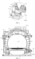
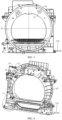
FIG. 1 is a schematic structural view of a front support assembly according to an embodiment of the present disclosure. -
FIG. 2 is an enlarged view of a structure A inFIG. 1 . -
FIG. 3 is an enlarged view of a structure B inFIG. 1 . -
FIG. 4 is a rear view of a front support assembly according to an embodiment of the present disclosure. -
FIG. 5 is a front view of a front support assembly according to an embodiment of the present disclosure. -
FIG. 6 is a schematic structural view of a front support according to an embodiment of the present disclosure. -
FIG. 7 is an enlarged view of a structure C inFIG. 6 . -
FIG. 8 is a schematic structural view of a steam generator according to an embodiment of the present disclosure. -
FIG. 9 is an exploded view of a steam generator according to an embodiment of the present disclosure. -
FIG. 10 is a schematic structural diagram of a water storage box according to an embodiment of the present disclosure. -
-
front support assembly 100, -
steam generator 10,generator body 11,steam outlet 111,heat insulation component 12,base 121, second recessedportion 1211,limit portion 1212,upper cover 122, first recessedportion 1221,clamp member 123,clamp section 1231,first fixing section 1232,second fixing section 1233,third fixing section 1234,first connection portion 13,second connection portion 14, first fixinghole 15, -
front support 20, opening 21, mountingportion 22,slot 23,support portion 24, mountingchamber 25,steam nozzle 26,vent opening 27 -
water storage box 30,insertion portion 301,water inlet 302,water outlet 303,replenishment opening 304,vent hole 305,first box 31, second box 32, mountingplate 33, limitpost 34, float ball 35, limit slot 36,magnetic member 37,buckle 38, -
water pump 40,air inflowing grille 50, andconnection pipe 60. - The embodiments of the present disclosure will be described in detail below with reference to examples thereof as illustrated in the accompanying drawings, throughout which same or similar elements, or elements having same or similar functions, are denoted by same or similar reference numerals. The embodiments described below with reference to the drawings are illustrative only, and are intended to explain rather than limit the present disclosure.
- In the description of the present disclosure, it is to be understood that, terms such as "center", "longitudinal", "lateral", "length", "width", "thickness", "over", "below", "front", "back", "left", "right", "vertical", "horizontal", "top", "bottom", "in", "out", "clockwise", "anticlockwise", "axial", "radial" and "circumference" refer to the directions and location relations which are the directions and location relations illustrated in the drawings, and for describing the present disclosure and for describing in simple, and which are not intended to indicate or imply that the device or the elements are disposed to locate at the specific directions or are structured and performed in the specific directions, which could not to be understood to the limitation of the present disclosure. Furthermore, the feature defined with "first" and "second" may comprise one or more this feature distinctly or implicitly. In the description of the present disclosure, "a plurality of" means two or more than two, unless specified otherwise.
- In the present disclosure, unless specified or limited otherwise, the terms "mounted", "connected", "coupled", and "fixed" are understood broadly, such as fixed, detachable mountings, connections, and couplings or integrated, and can be mechanical or electrical mountings, connections, and couplings, and also can be direct and via media indirect mountings, connections, and couplings, and further can be inner mountings, connections and couplings of two components, which can be understood by those skilled in the art according to the detail embodiment of the present disclosure.
- A laundry treatment device according to embodiments of the present disclosure is described below with reference to
FIGS. 1 to 10 . The laundry treatment device herein may be a dryer, a washing machine, a washer-dryer, etc. - As illustrated in
FIGS. 1 to 10 , the laundry treatment device according to an embodiment of the present disclosure comprises afront support 20 disposed at a front part of the laundry treatment device. - The laundry treatment device further comprises a
steam generator 10 having a steam generation chamber. Thesteam generator 10 is disposed at thefront support 20. Steam generated by thesteam generator 10 is introduced into a laundry treatment chamber to allow for steam drying and steam sterilization of laundry in the laundry treatment chamber. Compared to the related art in which thesteam generator 10 is disposed at a base of the laundry treatment device, providing thesteam generator 10 at thefront support 20 can shorten a pipeline distance of the steam to be introduced into the laundry treatment chamber and can avoid condensation of the steam into water in the pipeline. In this way, heat loss is reduced with an increased efficiency of drying the laundry. - The laundry treatment device further comprises a
water storage box 30 having a water storage chamber in communication with the steam generation chamber, and thewater storage box 30 is configured to supply water to thesteam generator 10. By providing thewater storage box 30, the water can be supplied to the steam generation chamber in real time during operation of thesteam generator 10, which realizes uninterrupted operation of thesteam generator 10 to provide a sufficient steam volume, and thus to improve a drying effect, a sterilization effect, etc., of the laundry. Thewater storage box 30 is disposed at thefront support 20, which is easy to mount and may be integrated to be mounted at a housing of the laundry treatment device, and stability of a fitting structure is good. At the same time, it is convenient to replenish water to thewater storage box 30 through thefront support 20, which is convenient to operate. - In the laundry treatment device according to the embodiments of the present disclosure, by providing the
water storage box 30 and thesteam generator 10, high-temperature steam may be generated to be introduced into the laundry treatment device for drying and sterilizing laundry. Thesteam generator 10 has the simple structure, is compact and easy to mount, and has low operating noise, and therefore user experience is good. Each of thewater storage box 30 and thesteam generator 10 is mounted at thefront support 20, occupying less space of the laundry treatment device and shortening the pipeline distance of thesteam generator 10 to reduce the heat loss. Moreover, fitting and the communication between thesteam generator 10 and thewater storage box 30 are convenient, and the overall structure has high strength and good stability. - As illustrated in
FIG. 1 , according to an embodiment of the present disclosure, thesteam generator 10 is disposed above thewater storage box 30, and thesteam generator 10 may be disposed at an upper part of thefront support 20. It can be understood that the upper part of thefront support 20 herein is an upper part relative to a middle position of thefront support 20, which does not extend beyond an upper edge of thefront support 20. Since thesteam generator 10 is disposed at the higher position and may be adjacent to a vent opening 27 of thefront support 20, a distance between thesteam generator 10 and thevent opening 27 is reduced, which avoids the condensation of the steam into water in the pipeline to reducing the heat loss. Thewater storage box 30 is disposed at a lower part of thefront support 20. It can be understood that the lower part of thefront support 20 herein is a lower part relative to a middle position of thefront support 20, which does not extend beyond a lower edge of thefront support 20. Since thewater storage box 30 is disposed at the lower position, it is more convenient for a user to feed water to thewater storage box 30 to improve ease of operation. Water in thewater storage box 30 can be pumped into the steam generation chamber of thesteam generator 10 by thewater pump 40. An overall layout is reasonable. - According to an embodiment of the present disclosure, the
steam generator 10 comprises agenerator body 11 and aheat insulation component 12. Thegenerator body 11 has the steam generation chamber, and thegenerator body 11 may generate high-temperature steam and has asteam outlet 111. Theheat insulation component 12 defines an accommodation chamber, and the accommodation chamber may be in communication with an ambient environment. Therefore, a part of thegenerator body 11 is disposed in the accommodation chamber. That is, theheat insulation component 12 is disposed at an outer side of thegenerator body 11. On the one hand, theheat insulation component 12 may have an insulation effect on thegenerator body 11 to prevent heat dissipation of the steam. On the other hand, theheat insulation component 12 may prevent direct emanation of the heat of thegenerator body 11 to structural members around the steam generator that leads to deformation, aging, etc., of the various structural members under a high temperature, and affects service life of the various structural members. In addition, theheat insulation component 12 may be cooperatively connected with thefront support 20 to realize the installation of thesteam generator 10 on thefront support 20. - In some examples, the
heat insulation component 12 has a connection portion, thefront support 20 has a mountingportion 22, theheat insulation component 12 has the connection portion, and the connection portion and the mountingportion 22 are in corresponding positions. Thesteam generator 10 is mounted and fixed through the mutual cooperation between the connection portion and the mountingportion 22. Here, the connection portion may be an insertion block, the mountingportion 22 is a slot, and the connection portion is inserted into and engaged with the mounting portion. The connection portion may also be a connection hole, the mountingportion 22 has a corresponding hole, and thesteam generator 10 is fixedly connected to thefront support 20 by a fastener. The connection portion and the mountingportion 22 may also be connected to each other in a snap-fit manner. In this way, the mounting is more convenient and fitting efficiency is improved. - It can be understood that the connection portion is disposed at the
heat insulation member 12, and therefore no additional fitting structure needs to be provided on thegenerator body 11, and thegenerator body 11 only needs to be mounted in the accommodation chamber of theheat insulation member 12. In this way, manufacture and fitting are convenient. - As illustrated in
FIG. 6 , in some embodiments, the mountingportion 22 is formed as a mounting post protruding from thefront support 20, a center of the mounting post has a mounting hole, the connection portion is formed as a connection hole, and thesteam generator 10 is fixedly connected to the mounting post by a fastener passing through the connection hole and the mounting hole of the positioning post. A plurality of connection portion can be provided, and a corresponding plurality of the positioning post is provided. Thus, the fixing effect of thesteam generator 10 can be improved. For example, the connection portion comprises afirst connection portion 13 and asecond connection portion 14, and thefirst connection portion 13 and thesecond connection portion 14 may be disposed at opposite sides of thesteam generator 10 respectively. Thus, a better fixing effect of thesteam generator 10 is achieved. Of course, a plurality offirst connection portion 13 can also be provided, and a plurality ofsecond connection portion 14 can also be provided, to further improve fixing stability of thesteam generator 10, and to prevent thesteam generator 10 from rotating, shaking, etc. - In addition, a plurality of support ribs can surround the mounting post to improve stability of the mounting post, and thus to improve mounting reliability of the
steam generator 10. - As illustrated in
FIG. 9 , according to an embodiment of the present disclosure, theheat insulation component 12 comprises abase 121 and anupper cover 122. Theupper cover 122 is provided on thebase 121, the accommodation chamber is defined between theupper cover 122 and thebase 121, and theupper cover 122 is detachably connected to thebase 121. Therefore, thegenerator body 11 is easily placed in the accommodation chamber. Here, the base 121 can be directly engaged with and fixed to theupper cover 122, for example, by a snap hook and a snap groove to be engaged and fixed, or by a fastener to be fixedly connected, or by other structural members to be engaged and connected. - As illustrated in
FIG. 9 , in some examples, theheat insulation component 12 further comprises aclamp member 123. Theclamp member 123 is disposed at an outer side of theupper cover 122 and thebase 121 and configured to tightly clamp and fixedly connect theupper cover 122 and thebase 121. That is, under a condition that theupper cover 122 is engaged with the base 121 in place, theupper cover 122 is fixedly connected to thebase 121 by wrapping the outer side of theupper cover 122 and the base 121 through theclamp member 123, eliminating a need to provide a fixing structure on theupper cover 122 and thebase 121. In this way, the structure of theupper cover 122 and thebase 121 is simplified while having the reliable connection and good structural stability. - According to an embodiment of the present disclosure, the
water storage box 30 has aslot 23, and thefront support 20 has aninsertion portion 301, and mounting of thewater storage box 30 is realized by theinsertion portion 301 being inserted into and engaged with theslot 23. In this way, the mounting is convenient. - According to another embodiment of the present disclosure, the
front support 20 has theslot 23, and thewater storage box 30 has theinsertion portion 301. Specifically, a side of thefront support 20 has asupport portion 24, and theslot 23 is provided on thesupport portion 24. Therefore, stability of theslot 23 can be improved. Thus, stability and reliability of the mounting of thewater storage box 30 are improved. A part of thewater storage box 30 protrudes outwardly to form theinsertion portion 301. That is, an outer wall surface of the part of thewater storage box 30 is directly inserted into and engaged with theslot 23. In this way, the engagement is convenient and reliable, eliminating a need to provide other engagement structures at thewater storage box 30, simplifying manufacturing process. Moreover, thewater storage box 30 is supported on thesupport portion 24, which is stable and prevents thewater storage box 30 from shaking, etc. - The
support portion 24 herein may be a support rib. The support rib has a simple structure, and is easy to be integrally molded with thefront support 20. Thesupport portion 24 may also be a support table. The support table can not only increase an engagement contact surface area to improve the stability, but also can increase the structural strength at theslot 23 to further improve the fitting stability of thewater storage box 30. - As illustrated in
FIG. 3 , according to an embodiment of the present disclosure, thewater storage box 30 comprises a mountingplate 33. The mountingplate 33 and a second box 32 of thewater storage box 30 are fixedly connected to each other or are integrally molded. A part of the mountingplate 33 may abut against thefront support 20 when thewater storage box 30 is fitted with thefront support 20, which realizes a type of positioning function and can improve the stability of thewater storage box 30. The mountingplate 33 may also be connected to thefront support 20 through the fastener, and therefore thewater storage box 30 is firmly fixed to thefront support 20. - As illustrated in
FIG. 10 , according to an embodiment of the present disclosure, thewater storage box 30 comprises afirst box 31 and a second box 32. The second box 32 is disposed above thefirst box 31 and sealingly engaged with thefirst box 31 to define the water storage chamber, which can be sealed by a seal member or by a seal adhesive to avoid water leakage at the connection. The second box 32 may also be engaged with thefirst box 31 through welding, which is easy to operate and has high reliability of sealing. - The second box 32 has a
water inlet 302, and thefirst box 31 has awater outlet 303. Thewater inlet 302 and thewater outlet 303 are in communication with the water storage chamber, and thewater outlet 303 is in communication with thesteam generator 10. Therefore, water in the water storage chamber can be introduced into the steam generation chamber. Furthermore, since thewater inlet 302 is located at an upper part and thewater outlet 303 is located at a lower part, the water in the water storage chamber can be easily emptied out and can circulate and flow to avoid residue of stagnant water, etc. - According to an embodiment of the present disclosure, the
water storage box 30 further comprises a water level detector. The water level detector may be disposed in the water storage chamber or outside the water storage chamber. For example, the water level detector is an infrared sensor, which detects a water volume in the water storage chamber by an infrared means. - As illustrated in
FIG. 10 , in some embodiments, the water level detector comprises a float ball 35 and amagnetic member 37. The float ball 35 is disposed in the water storage chamber, themagnetic member 37 is disposed at an outer side of thewater storage box 30, and the outer side of thewater storage box 30 is further provided with a closed loop formed by wires. The float ball 35 and themagnetic member 37 cooperate with each other, and it can be understood that the float ball 35 is provided with a magnet, and using the principle of electromagnetic induction, the float ball 35 moves and is away from themagnetic member 27 to allow magnetic flux to change and a current of the closed loop to change. As a water volume changes, a distance between the float ball 35 and themagnetic member 27 gradually becomes larger. When a certain distance is reached, i.e., when the water level reaches a predetermined level, an alarm is prompted, etc., to realize a detection of the water level in the water storage chamber. - As illustrated in
FIG. 10 , in some embodiments, the water storage chamber is provided with alimit post 34. An upper end of thelimit post 34 is connected to the second box 32. The float ball 35 may be sleeved on thelimit post 34 and may move in a direction of thelimit post 34, and the float ball 35 is slidingly engaged with thelimit post 34. By providing thelimit post 34, the float ball 35 can be avoided from moving horizontally, and the detection of the water level is thus prevented from being affected. A top of the second box 32 is provided with a limit slot 36, and themagnetic member 37 is adapted to be inserted into the limit slot 36 to realize fixing of themagnetic member 37, which is simple in structure and convenient in mounting. - As illustrated in
FIG. 3 , according to an embodiment of the present disclosure, thefront support 20 has awater replenishment opening 304, thewater replenishment opening 304 is in communication with thewater inlet 302 of thewater storage box 30, and thewater replenishment opening 304 is located at higher level than thewater inlet 302. It can be understood that a user can feed water into thewater storage box 30 through thewater replenishment opening 304, and thewater replenishment opening 304 is provided at anopening 21 of thefront support 20 to facilitate an operation of the user; and since thewater replenishment opening 304 is located at higher level than thewater inlet 302, information about full water feeding can be obtained when water overflows from thereplenishment opening 304, preventing excessive water in the water storage box from overflowing into an interior of the laundry treatment device, and preventing affecting normal use of other structural members. - As illustrated in
FIG. 1 , in some examples, thefront support 20 has theopening 21 provided at the middle part of thefront support 20, theopening 21 is in communication with the laundry treatment chamber of the laundry treatment device, and the user can put the laundry into the laundry treatment chamber through theopening 21. Thewater replenishment opening 304 is in communication with theopening 21, that is, the user can replenish water to thewater storage box 30 through thewater replenishment opening 304 when theopening 21 is opened, and thewater replenishment opening 304 is covered when theopening 21 is closed. In this way, thewater replenishment opening 304 is not exposed, which is aesthetically pleasing and can avoid being contaminated. - As illustrated in
FIG. 1 , the laundry treatment device further comprises anair inflowing grille 50 movably disposed at thefront support 20. Theair inflowing grille 50 can realize a ventilation effect while preventing the laundry from being rolled into the air duct. A part of an end portion of theair inflowing grille 50 is recessed downwardly to form a replenishment chamber, and the replenishment chamber has areplenishment opening 304 provided at a bottom wall of the replenishment chamber. Thereplenishment opening 304 is connected to thewater storage box 30 through aconnection pipe 60, and thewater storage box 30 is connected to thewater storage box 30 through theconnection pipe 60. Therefore, water can be replenished to thewater storage box 30 through the water replenishment chamber, and when the water in the water replenishment chamber is no longer flowing to thewater storage box 30, information about the full water feeding into thewater storage box 30 is obtained, preventing the excessive water in thewater storage box 30 from overflowing into the interior of the laundry treatment device. The water in the water replenishment chamber is temporarily stored in the water replenishment chamber, and the water in the water storage chamber automatically flows to the water storage chamber after flowing to the steam generation chamber, to avoid the overflowing of the water through thewater replenishment opening 304 that affects the user's usage effect. And the position of thewater replenishment opening 304 is relatively concealed without affecting an appearance of theair inflowing grille 50, and effectively utilizes an occupied space of theair inflowing grille 50 to improve a space utilization rate. - In addition, a cover is provided at the
water replenishment port 304, and the cover is opened to pour water before steam is required. By providing the cover to cover thewater replenishment opening 304, lint or foreign matter can be avoided from entering, and the foreign matter is prevented from blocking thewater replenishment opening 304. - In some embodiments, the laundry treatment device further comprises a
water pump 40 disposed at thefront support 20 and connected between thewater outlet 303 and thesteam generator 10. Specifically, thesteam generator 10 is disposed at the upper part of thefront support 20 to facilitate proximity of thesteam generator 10 to the vent opening 27 disposed at the upper portion of thefront support 20. Thewater storage box 30 is disposed at the lower part of thefront support 20, thewater outlet 303 of thewater storage box 30 is connected to a water inlet end of thewater pump 40 through theconnection pipe 60, and a water outlet end of thewater pump 40 is connected to thesteam generator 10 through theconnection pipe 60. Therefore, thewater pump 40 can pump the water from thewater storage box 30 into thesteam generator 10. Since thewater pump 40 is also disposed at thefront support 20, the cooperative connection of thewater pump 40 to thewater storage box 30 and thesteam generator 10 is facilitated. - As illustrated in
FIG. 5 , in some embodiments, asteam nozzle 26 disposed at the upper portion of thefront support 20 is provided. Thesteam nozzle 26 is adjacent to thesteam generator 10 and adapted to be in communication with the steam generation chamber. Specifically, thesteam nozzle 26 defines thevent opening 27 and is fixed to thefront support 20 through the fastener, and thesteam generator 20 may be connected to thesteam nozzle 26 through theconnection pipe 60. Therefore, the steam can be introduced to thevent opening 27 and be introduced into the laundry treatment chamber through thevent opening 27. Thevent opening 27 may comprise a plurality of small holes to achieve a spraying effect. Thus, the steam can be uniformly sprayed onto the laundry in the laundry treatment chamber. - A laundry treatment device according to embodiments of the present disclosure is described below with reference to
FIGS. 1 to 10 . - The laundry treatment device comprises a laundry treatment tub, a
front support 20, asteam generator 10, awater storage box 30, and awater pump 40. - The laundry treatment tub defines a laundry treatment chamber. The
front support 20 is disposed at a front part of the laundry treatment device. A middle part of thefront support 20 has anopening 21 in communication with the laundry treatment chamber. Anair inflowing grille 50 is disposed at thefront support 20, which not only can realize a ventilation effect but also can prevent the laundry from being rolled into an air duct of thefront support 20. - A part of an end of the
air inflowing grille 50 is recessed downwardly to form a water replenishment chamber, and the replenishment chamber has awater replenishment opening 304 provided at a bottom wall of the water replenishment chamber. Thewater replenishment opening 304 is connected to thewater storage box 30 through theconnection pipe 60, and the position of thewater replenishment opening 304 is relatively concealed without affecting the appearance of theair inflowing grille 50 and effectively utilizes the occupied space of theair inflowing grille 50 to improve the space utilization rate. The water replenishment chamber is provided with a cover detachably disposed at theair inflowing grille 50 and configured to open and close an opening of the water replenishment chamber, and foreign matter can be prevented from blocking thewater replenishment opening 304 by providing the cover. Furthermore, a part of another end of theair inflowing grille 50 is recessed downwardly to form an accommodation recess configured to accommodate the aromatherapy, and the accommodation recess has an emanation hole disposed at a bottom wall of the accommodation recess and/or a side wall of the accommodation recess to facilitate emanation of the aromatherapy. - A
steam nozzle 26 disposed at an upper part of thefront support 20 is provided. Thesteam nozzle 26 defines avent opening 27 in communication with theopening 21. Thefront support 20 further has a mountingportion 22. The mountingportion 22 is formed as a mounting post protruding from thefront support 20. A center of the mounting post has a mounting hole, and a plurality of support ribs can surround the mounting post to improve stability of the mounting post. - The
front support 20 comprises a support plate at a front side of the laundry treatment chamber. It can be understood that the support plate herein extends in a left-right direction and an up-down direction, and the support plate is further provided with a structural member such as a protruding rib protruding from a rear side surface of the support plate to increase structural strength and to facilitate a fitting with other structural members. Theopening 21 is located at a middle part of the support plate, and theair inflowing grille 50 is mounted below theopening 21. Theair inflowing grille 50 cooperates with the support plate, and thesteam generator 10 and thewater storage box 30 are disposed at the support plate. Specifically, thesteam generator 10 and thewater storage box 30 are fixedly mounted at a rear side of the support plate, and each of thewater storage box 30 and thesteam generator 10 is disposed at a left side of theair inflowing grille 50, or, each of thewater storage box 30 and thesteam generator 10 may also be disposed at a right side of theair inflowing grille 50. Thewater storage box 30 can be cooperatively connected to thesteam generator 10 through aconnection pipe 60 at a side of theair inflowing grille 50 for easy connection. Of course, thewater storage box 30 and thesteam generator 10 are disposed at opposite sides of theair inflowing grille 50. - The
steam generator 10 is disposed at thefront support 20 and located at the upper part of thefront support 20. It can be understood that the upper part of thefront support 20 herein is an upper part relative to a middle position of thefront support 20, which does not extend beyond an upper edge of thefront support 20, to improve reasonableness and compactness of an overall structural layout, and thesteam generator 10 is adjacent to thesteam nozzle 26 and connected to thesteam nozzle 26 through theconnection pipe 60. - As illustrated in
FIGS. 8 and9 , thesteam generator 10 comprises agenerator body 11 and aheat insulation component 12. Thegenerator body 11 has an end having a water inlet and another end having asteam outlet 111. Thegenerator body 11 is further provided with a connection terminal to facilitate a connection of thegenerator body 11 to a control circuit. Theheat insulation component 12 defines an accommodation chamber, and the accommodation chamber is in communication with an ambient environment. Therefore, a part of thegenerator body 11 is disposed in an accommodation chamber, and thesteam outlet 111 of thegenerator body 11 can protrude from the accommodation chamber to facilitate a connection of thesteam outlet 111 to avent opening 27. By disposing theheat insulation component 12 at an outer side of thegenerator body 11, on the one hand, theheat insulation component 12 can have an insulation effect on thegenerator body 11 to prevent heat dissipation of the steam, on the other hand, theheat insulation component 12 can prevent direct emanation of the heat of thegenerator body 11 to structural members around the steam generator that leads to deformation, aging, etc., of the various structural members under a high temperature, and affects service life of the various structural members. - As illustrated in
FIG. 9 , theheat insulation component 12 comprises abase 121, anupper cover 122, and aclamp member 123. Theupper cover 122 is disposed on thebase 121, the accommodation chamber is defined between theupper cover 122 and thebase 121, and theupper cover 122 is detachably connected to thebase 121. Therefore, thegenerator body 11 is easily placed in the accommodation chamber. Theupper cover 122 and the base 121 are made of a high-temperature resistant material member, for example, a fiberglass mixture, which is chemically inert in many cases, has high strength, good stability, a high safety factor, lightweight, high-temperature resistance, and lower cost, and is easy to promote and use. Further, theclamp member 123 can also be made of a high-temperature resistant material member to improve an effect of heat insulation and heat preservation of the overall structure. Of course, theclamp member 123 can also adopt a metallic member, which has high structural strength and can tightly clamp and fixedly connect theupper cover 122 and thebase 121. - The
base 121 has a notch formed at a left side and a right side of thebase 121, and the accommodation chamber can be connected to the ambient environment by the notch. Thegenerator body 11 has an end having a water inlet joint and a line joint, and another end having an air outflowing joint. The water inlet joint, the line joint, and the air outflowing joint can protrude from the accommodation chamber through the notch to facilitate a connection of water inlet joint, the line joint, and the air outflowing joint to the ambient environment. Thebase 121 is further provided with a support rib protruding from an inner wall surface of thebase 121. When thegenerator body 11 is mounted in the accommodation chamber, the support rib can serve a function in positioning, limiting, and supporting, to improve stability of thegenerator body 11. The accommodation chamber has a shape substantially same as a structure of thegenerator body 11 to avoid interference, shaking, etc., of thegenerator body 11 in the accommodation chamber, which affects performance and service life of thegenerator body 11. In addition, in a length direction of thesteam generator 10, theupper cover 122 has a size larger than a size of thebase 121. As illustrated inFIG. 9 , theupper cover 122 has an end that can extend above the water inlet joint and the line joint and thus can provide protection to the joints to prevent damage to the joints caused by collision, water ingress of the line joint, etc., that affect normal use of the joints. Theupper cover 122 has another end that can extend to the air outflowing joint to further protect the air outflowing joint. - As illustrated in
FIG. 9 , specifically, thebase 121 is provided with alimit portion 1212 at a side of the base 121 facing towards theupper cover 122, and thelimit portion 1212 is formed as a limit rib protruding from an upper surface of thebase 121; and theupper cover 122 is provided with an engagement portion (not illustrated in theFIG. 9 ) at a side of theupper cover 122 facing towards thebase 121, and the engagement portion is formed as an engagement groove. The engagement groove has a shape corresponding to a shape of the limit rib, and thelimit portion 1212 can be engaged with the engagement portion. The limit rib can be an elongated rib. Two limit ribs are provided and are symmetrically arranged in a width direction of thebase 121, and each of the two limit ribs extends in a length direction of thebase 121. - Providing the
limit portion 1212 and the engagement portion can serve a function in positioning and limiting the fitting of theupper cover 122 and thebase 121, which facilitates locking of theupper cover 122 and the base 121 while preventing the connection between theupper cover 122 and the base 121 from shaking and interfering with thegenerator body 11, etc. In addition, theupper cover 122 is engaged with the base 121 in place to facilitate the mounting of theclamp member 123, which is convenient for positioning and mounting and has good engagement reliability. - As illustrated in
FIG. 9 , theclamp member 123 is disposed at an outer side of theupper cover 122 and thebase 121 and configured to tightly clamp and fixedly connect theupper cover 122 and thebase 121. Specifically, theclamp member 123 comprises aclamp section 1231, afirst fixing section 1232, asecond fixing section 1233, and athird fixing section 1234. Theclamp section 1231 is substantially formed into an annular shape with an opening and surrounds the outer side of theupper cover 122 and thebase 121. Specifically, theupper cover 122 has a first recessedportion 1221 at an outer surface of theupper cover 122, thebase 121 has a second recessedportion 1211 at an outer surface of thebase 121, and the second recessedportion 1211 and the first recessedportion 1221 are in corresponding positions. A part of theclamp section 1231 is engaged with the first recessedportion 1221, and another part of theclamp section 1231 is engaged with the second recessedportion 1211. It can be appreciated that the first recessedportion 1221 extends along the outer surface of theupper cover 122 to form a half-annular shape, and the second recessedportion 1211 extends along the outer surface of the base 121 to form a half-annular shape. The first recessedportion 1221 cooperates with the second recessedportion 1211 to form an annular-shaped recess, and theclamp section 1231 can be mounted in the annular-shaped recess formed by the two recessed portions and realizes an insertion-type of engagement mounting, thereby preventing detachment of theclamp section 1231 from theupper cover 122 and thebase 121, avoiding a fixing failure, and improving the stability of the overall structure. - As illustrated in
FIGS. 2 ,6 , and8 , thefirst fixing section 1232 is disposed at an end of theclamp section 1231, and thesecond fixing section 1233 is disposed at another end of theclamp section 1231. Thefirst fixing section 1232 has afirst fixing hole 15, and thesecond fixing section 1233 has a second fixing hole. The second fixing hole and the first fixinghole 15 are in corresponding positions, and thefirst fixing section 1232 is fixedly connected to thesecond fixing section 1233 by the fastener passing through the first fixinghole 15 and the second fixing hole. Thus, theclamp section 1231 can be closely attached to theupper cover 122 and thebase 121, and theupper cover 122 and the base 121 can be fixed through theclamp member 123. The fastener herein may be a bolt, which is easy to connect and has good stability. - The
first fixing section 1232 and thesecond fixing section 1233 are located at the upper part of thegenerator body 11, afirst connection portion 13 is disposed at thefirst fixing section 1232, thethird fixing section 1234 can be located at the lower part of thegenerator body 11, and asecond connection portion 14 is disposed at thethird fixing section 1234. That is, thefirst fixing section 1232 and thesecond fixing section 1233 are located at a first side of thegenerator body 11, and thethird fixing section 1234 is located at a side of thegenerator body 11 opposite to the first side of thegenerator body 11, and each of thefirst connection portion 13 and thesecond connection portion 14 is formed as a connection hole, and thesteam generator 10 is fixed to thefront support 20 by the fasteners passing through the connection hole and the mounting hole of the positioning post. Fixed mounting by means of the connection portions on the two sides can improve the fixing effect of thesteam generator 10 with good stability. - As illustrated in
FIG. 10 , thewater storage box 30 comprises afirst box 31 and a second box 32. The second box 32 is disposed above thefirst box 31 and engaged with thefirst box 31 through welding to define a water storage chamber. Water leakage is avoided at the connection through the welding. The second box 32 has awater inlet 302, and thefirst box 31 has awater outlet 303. Thewater inlet 302 and thewater outlet 303 are in communication with the water storage chamber. Thewater inlet 302 is located at an upper part, and thewater outlet 303 is located at a lower part, and therefore the water in the water storage chamber can be easily emptied out and can circulate and flow to avoid residue of stagnant water, etc. - As illustrated in
FIGS. 3 ,6 , and7 , thewater storage box 30 is disposed at thefront support 20 and located at a lower part of thefront support 20. It can be understood that the lower part of thefront support 20 herein is a lower part relative to a middle position of thefront support 20, which does not extend beyond a lower edge of thefront support 20, to improve the reasonableness and compactness of the overall structural layout. Thefront support 20 has aslot 23, thewater storage box 30 is provided with aninsertion portion 301. Specifically, thefront support 20 has asupport portion 24 at a side of thefront support 20. Thesupport portion 24 can be a support table or a support rib, and theslot 23 is disposed at thesupport portion 24. Therefore, the stability of theslot 23 can be improved. Thus, the stability and reliability of the mounting of thewater storage box 30 can be improved. A part of thewater storage box 30 protrudes outwardly to form theinsertion portion 301. That is, an outer wall surface of the part of thewater storage box 30 is directly inserted into and engaged with theslot 23. In this way, the engagement is convenient and reliable, eliminating a need to provide other engagement structures at thewater storage box 30, simplifying manufacturing process. Moreover, thewater storage box 30 is supported on thesupport portion 24, which is stable and prevents thewater storage box 30 from shaking, etc. Meanwhile, a space feature of thefront support 20 is fully utilized to improve the stability of the structure. - Two
slots 23 are arranged opposite to each other, and twocorresponding support portions 24 are provided. Each of the twoslots 23 is supported on thecorresponding support portion 24. The twosupport portions 24 can have the same structures, for example, each of the twoslots 23 is supported on the support table, or each of the twoslots 23 is supported on the support rib. As illustrated inFIG. 7 , in some examples, the twosupport portions 24 can also have different structures. One of the twoslots 23 is supported on the support table, and the other of the twoslots 23 is supported on the support rib. A mountingchamber 25 is defined between the twosupport portions 24, and a part of thewater storage box 30 is mounted in the mountingchamber 25. That is, when an outer wall surface of thewater storage box 30 is supported on the twoslots 23, the part of thewater storage box 30 can be inserted into the mountingchamber 25, which can realize full utilization of the space of thefront support 20 and increase a water storage volume of thewater storage box 30. Furthermore, a part of thewater storage box 30 is disposed at a middle of the twoslots 23, and the mountingchamber 25 has a size matching a size of this part of thewater storage box 30, which can increase the stability of the structure to avoid the shaking of thewater storage box 30. - The
water storage box 30 has a mountingplate 33. As illustrated inFIGS. 3 ,7 , and10 , the mountingplate 33 extends in a left-right direction and has a connection hole formed thereon, thefront support 20 has a mounting post having a mounting hole, and the mountingplate 33 has a bent section extending rearwardly at a right edge of the mountingplate 33. The bent section abuts against a part of thefront support 20 when thewater storage box 30 is inserted into theslot 23. The mountingplate 33 is fixedly connected to thefront support 20 by the fastener passing through the connection hole and the mounting post. Therefore, thewater storage box 30 is firmly fixed to thefront support 20. - In addition, as illustrated in
FIGS. 1 and3 , thewater storage box 30 is located at a lower part of thefront support 20, and thewater storage box 30 is connected to a replenishment chamber through aconnection pipe 60. Therefore, water can be fed into thewater storage box 30 through areplenishment opening 304. Thewater replenishment opening 304 is in communication with thewater inlet 302 of thewater storage box 30, and thewater inlet 302 is located at higher level than the water replenishment chamber. It can be understood that a user can feed water into thewater storage box 30 through thewater replenishment opening 304, and thewater replenishment opening 304 is provided at anopening 21 of thefront support 20 to facilitate an operation of the user that information about full water feeding can be obtained when water overflows from thereplenishment opening 304, preventing excessive water in the water storage box from into an interior of the laundry treatment device, and preventing affecting normal use of other structural members; and thewater replenishment opening 304 is located at a lower part of the laundry treatment device and is located at a lower part of theopening 21 configured to put the laundry, and therefore the user can conveniently perform a water replenishment operation even when the laundry treatment device is placed in a higher position. - The
water storage box 30 further comprises a water level detector. The water level detector can be disposed in the water storage chamber or outside of the water storage chamber. For example, the water level detector is an infrared sensor, which detects a water volume in the water storage chamber by an infrared means. - As illustrated in
FIG. 10 , the water level detection device comprises a float ball 35 and amagnetic member 37. The float ball 35 is disposed in the water storage chamber, and themagnetic member 37 is disposed at an outer side of thewater storage box 30. Specifically, the water storage chamber is provided with alimit post 34. Thelimit post 34 can be integrally molded at the second box 32 or can be engaged with and connected to the second box 32 to allow an upper end of thelimit post 34 to be connected to the second box 32. The float ball 35 can be sleeved on thelimit post 34 and can move in a direction of thelimit post 34, and the float ball 35 is slidingly engaged with thelimit post 34. By providing thelimit post 34, the float ball 35 can be avoided from moving horizontally, and the detection of the water level is thus prevented from being affected. - A top of the second box 32 is provided with a limit slot 36. The
magnetic member 37 is adapted to be inserted into the limit slot 36 to realize fixing of themagnetic member 37. The outer side of thewater storage box 30 is further provided with a closed loop formed by wires. Specifically, the float ball 35 and themagnetic member 37 cooperate with each other, the float ball 35 is provided with a magnet, and using the principle of electromagnetic induction, the float ball 35 moves and is away from themagnetic member 27 to allow magnetic flux to change and a current of the closed loop to change. As a water volume changes, a distance between the float ball 35 and themagnetic member 27 gradually becomes larger. When a certain distance is reached, i.e., when the water level reaches a predetermined level, an alarm is prompted, etc., to realize a detection of the water level in the water storage chamber. - As illustrated in
FIGS. 3 and10 , thewater storage box 30 further has avent hole 305. Thevent hole 305 is provided at the top of the second box 32 and configured to connect the water storage chamber to the ambient environment. It can be ensured that the water storage chamber is always connected to the ambient environment by providing thevent hole 305, avoiding formation of a negative pressure state in the water storage chamber, which affects outflowing of water. By providing thevent hole 305 at the top of the second box 32, automatic outflowing or overflowing of the water in the water storage chamber can be avoided. - In some embodiments, a part of an upper surface of the second box 32 protrudes upwardly to form a protrusion, the
vent hole 305 is provided at a top of the protrusion, an avoidance portion is formed between the protrusion and thewater storage box 30, and the mountingplate 33 is disposed at the avoidance portion. Therefore, the fitting of thewater storage box 30 and thefront support 20 is facilitated, and the space utilization rate is further improved. - The
water pump 40 is connected between thewater outlet 303 and thesteam generator 10, thewater outlet 303 of thewater storage box 30 is connected to a water inlet end of thewater pump 40 through theconnection pipe 60, and a water outlet end of thewater pump 40 is connected to thesteam generator 10 through theconnection pipe 60. Therefore, thewater pump 40 can pump the water from thewater storage box 30 into thesteam generator 10. Thewater pump 40 is fixedly connected to a positioning post of thefront support 20 through the fastener, and therefore the cooperative connection of thewater pump 40 to thewater storage box 30 and thesteam generator 10 is facilitated. - In the laundry treatment device according to the embodiments of the present disclosure, the
steam generator 10 is disposed at thefront support 20 and adjacent to anair vent 27, which can prevent loss of steam heat generated by thesteam generator 10 in the pipeline. In this way, a reduction in a steam outflowing volume is avoided to increase a steam volume introduced into the laundry treatment chamber, which in turn can increase the drying efficiency of the laundry. By disposing thewater storage box 30 at thefront support 20, the fitting is convenient. And since thewater storage box 30 is disposed at the lower position, it is more convenient for the user to feed water to thewater storage box 30 to improve the ease of the operation. By disposing theheat insulation component 12 at thesteam generator 10, the loss of the steam heat can be prevented to improve a steam utilization rate, and meanwhile, emanation of high-temperature gas into surrounding structural members can be prevented to avoid aging, deformation, etc., of the various structural members. In this way, feasibility of the mounting and use of thesteam generator 10 is ensured. - Other compositions as well as operations of the laundry treatment device according to embodiments of the present disclosure are known to those of ordinary skill in the art, and will not be described in detail herein. The up-down direction, the left -right direction, and the front-rear direction are based on the up-down direction, the left -right direction, and the front-rear direction illustrated in the drawings.
- In the description of the present disclosure, a first characteristic "on" or "under" a second characteristic refers to the first characteristic and the second characteristic can be direct or via their another characteristic indirect mountings, connections, and couplings, and the first characteristic "on", "above", "over" the second characteristic may refer to the first characteristic is right over the second characteristic or is diagonal above the second characteristic, or just refer to the horizontal height of the first characteristic is higher than the horizontal height of the second characteristic.
- In the description of the present disclosure, reference throughout this specification to "an embodiment", "some embodiments", "an exemplary embodiment", "an example", "a specific example", or "some examples" means that a particular feature, structure, material, or characteristic described in connection with the embodiment or example is comprised in at least one embodiment or example of the present disclosure. In the present disclosure, the appearances of the phrases in various places throughout this specification are not necessarily referring to the same embodiment or example of the present disclosure. Furthermore, the particular features, structures, materials, or characteristics may be combined in any suitable manner in one or more embodiments or examples.
- Although embodiments of the present disclosure have been illustrated and described, it is conceivable for those of ordinary skill in the art that various changes, modifications, replacements, and variations can be made to these embodiments without departing from the principles and spirit of the present disclosure. The scope of the present disclosure shall be defined by the claims as appended and their equivalents.
Claims (17)
- A laundry treatment device, comprising:a front support (20);a steam generator (10) having a steam generation chamber; anda water storage box (30) having a water storage chamber in communication with the steam generation chamber,wherein each of the water storage box (30) and the steam generator (10) is disposed at the front support (20).
- The laundry treatment device according to claim 1, wherein the steam generator (10) is disposed above the water storage box (30).
- The laundry treatment device according to claim 1, wherein the steam generator (10) comprises:a generator body (11) having a steam outlet (111); anda heat insulation component (12) defining an accommodation chamber in communication with an ambient environment, wherein at least a part of the generator body (11) is disposed in the accommodation chamber, and wherein the heat insulation component (12) is adapted to be cooperatively connected to the front support (20).
- The laundry treatment device according to claim 3, wherein:the front support (20) has a mounting portion (22); andthe heat insulation component (12) has a connection portion, the connection portion and the mounting portion (22) being in a corresponding position and being engaged with each other.
- The laundry treatment device according to claim 4, wherein:the mounting portion (22) is formed as a mounting post protruding from the front support (20); andthe connection portion is formed as a connection hole, the mounting portion (22) being fixedly connected to the connection portion by a fastener passing through the connection hole.
- The laundry treatment device according to claim 3, wherein the heat insulation component (12) comprises:a base (121);an upper cover (122) disposed on the base (121), the accommodation chamber being defined between the upper cover (122) and the base (121); anda clamp member (123) disposed at an outer side of the upper cover (122) and the base (121) and tightly clamping and fixedly connecting the upper cover (122) to the base (121).
- The laundry treatment device according to any one of claims 1 to 6, wherein:one of the water storage box (30) and the front support (20) has a slot (23); andthe other one of the water storage box (30) and the front support (20) has an insertion portion (301), the insertion portion (301) being inserted into and engaged with the slot (23).
- The laundry treatment device according to claim 7, wherein:the front support (20) has a support portion (24) formed as a support table;the slot (23) is disposed at the support table; anda part of the water storage box (30) protrudes outwardly to form the insertion portion (301).
- The laundry treatment device according to claim 7, wherein the water storage box (30) comprises: a mounting plate (33), at least part of the mounting plate (33) abutting against the front support (20), and the mounting plate (33) being connected to the front support (20) by a fastener.
- The laundry treatment device according to any one of claims 1 to 9, wherein the water storage box (30) comprises:a first box (31) having a water outlet (303) in communication with the steam generator (10); anda second box (32) disposed above the first box (31) and sealingly engaged with the first box (31) to define the water storage chamber, the second box (32) having a water inlet (302),wherein the second box (32) is engaged with the first box (31) through welding.
- The laundry treatment device according to any one of claims 1 to 10, further comprising:
a water level detector disposed in the water storage box (30) and detecting a water level in the water storage chamber. - The laundry treatment device according to claim 11, wherein the water level detector comprises:a float ball (35) disposed in the water storage chamber; anda magnetic member (37) disposed at an outer side of the water storage box (30), the float ball (35) and the magnetic member (37) cooperating with each other to detect the water level in the water storage chamber.
- The laundry treatment device according to any one of claims 1 to 12, wherein the front support (20) has a water replenishment opening (304), the water replenishment opening (304) being in communication with the water inlet (302) of the water storage box (30) and located at higher level than the water inlet (302).
- The laundry treatment device according to claim 13, wherein a middle part of the front support (20) has an opening (21) in communication with a laundry treatment chamber of the laundry treatment device and in communication with the water replenishment opening (304).
- The laundry treatment device according to claim 13, further comprising:an air inflowing grille (50) movably disposed at the front support (20), the air inflowing grille (50) having the water replenishment opening (304) and a water replenishment chamber,wherein the water storage box (30) is connected to the replenishment chamber through a connection pipe.
- The laundry treatment device according to any one of claims 1 to 15, further comprising:
a water pump (40) disposed at the front support (20) and connected between the water storage box (30) and the steam generator (10), the water pump pumping (40) water from the water storage box (30) into the steam generator (10). - The laundry treatment device according to any one of claims 1 to 16, wherein a steam nozzle (26) disposed at an upper part of the front support (20) is provided, the steam nozzle (26) being adjacent to the steam generator (10) and adapted to be in communication with the steam generation chamber.
Applications Claiming Priority (3)
| Application Number | Priority Date | Filing Date | Title |
|---|---|---|---|
| CN202122072485.3U CN215906412U (en) | 2021-08-30 | 2021-08-30 | Clothes treating device |
| CN202111007041.XA CN115726126B (en) | 2021-08-30 | 2021-08-30 | Clothing processing device |
| PCT/CN2021/127679 WO2023029193A1 (en) | 2021-08-30 | 2021-10-29 | Laundry treatment device |
Publications (2)
| Publication Number | Publication Date |
|---|---|
| EP4368760A1 true EP4368760A1 (en) | 2024-05-15 |
| EP4368760A4 EP4368760A4 (en) | 2024-09-18 |
Family
ID=85410800
Family Applications (1)
| Application Number | Title | Priority Date | Filing Date |
|---|---|---|---|
| EP21955722.0A Pending EP4368760A4 (en) | 2021-08-30 | 2021-10-29 | Laundry treatment device |
Country Status (2)
| Country | Link |
|---|---|
| EP (1) | EP4368760A4 (en) |
| WO (1) | WO2023029193A1 (en) |
Family Cites Families (12)
| Publication number | Priority date | Publication date | Assignee | Title |
|---|---|---|---|---|
| WO2006129916A1 (en) * | 2005-05-31 | 2006-12-07 | Lg Electronics Inc. | Laundry machine |
| KR20070078328A (en) * | 2006-01-26 | 2007-07-31 | 엘지전자 주식회사 | Steam generator and washing machine using same |
| DE102007023020B3 (en) * | 2007-05-15 | 2008-05-15 | Miele & Cie. Kg | Front loadable laundry treatment machine i.e. washing machine, has inlet valve controlling water supply to inlet opening of steam generation device, where free flow section is arranged between inlet valve and inlet opening of tank |
| DE102009047154A1 (en) * | 2009-11-25 | 2011-06-16 | BSH Bosch und Siemens Hausgeräte GmbH | Laundry treatment appliance with a steam generator and method for operating a laundry treatment appliance |
| ITTO20110814A1 (en) * | 2011-09-12 | 2013-03-13 | Indesit Co Spa | DRYER MACHINE OR WASHING MACHINE INCLUDING AN ACCESS BOARD CONTAINING MEANS FOR THE GENERATION OF STEAM FOR THE TREATMENT OF CLOTHS |
| EP2642012B1 (en) * | 2012-03-22 | 2019-05-08 | Electrolux Home Products Corporation N.V. | Laundry machine and method of laundry treatment in a laundry machine |
| KR101367400B1 (en) * | 2012-09-04 | 2014-02-24 | 엘지전자 주식회사 | Steam injection apparatus and fabric dryer having the same |
| PL2818593T3 (en) * | 2013-06-25 | 2022-01-31 | Electrolux Appliances Aktiebolag | Laundry treatment apparatus having a water reservoir |
| DE102017221722A1 (en) * | 2017-12-01 | 2019-06-06 | BSH Hausgeräte GmbH | Spray unit and laundry treatment device |
| CN208748389U (en) * | 2018-08-27 | 2019-04-16 | 无锡小天鹅股份有限公司 | Clothes treatment device |
| CN112921606A (en) * | 2021-03-18 | 2021-06-08 | 创维电器股份有限公司 | Drum-type clothes dryer with thin film steam generator |
| CN113201911B (en) * | 2021-04-13 | 2022-03-22 | 无锡小天鹅电器有限公司 | Steam generator and clothes treatment equipment with same |
-
2021
- 2021-10-29 EP EP21955722.0A patent/EP4368760A4/en active Pending
- 2021-10-29 WO PCT/CN2021/127679 patent/WO2023029193A1/en not_active Ceased
Also Published As
| Publication number | Publication date |
|---|---|
| WO2023029193A1 (en) | 2023-03-09 |
| EP4368760A4 (en) | 2024-09-18 |
Similar Documents
| Publication | Publication Date | Title |
|---|---|---|
| AU2006280592A1 (en) | Drying duct assembly and washing machine having the same | |
| CN209958109U (en) | Clothes treating apparatus | |
| CN115726126B (en) | Clothing processing device | |
| CN215906425U (en) | Clothes treatment device and front support assembly thereof | |
| CN113564882B (en) | Clothes processing device and front support assembly thereof | |
| CN215906412U (en) | Clothes treating device | |
| CN211713438U (en) | Clothes treating apparatus | |
| EP3252217B1 (en) | Heat pump mounting box for heat pump drier or heat pump washer-drier machine | |
| CN222744643U (en) | A heating component, a drying module and a clothing processing device | |
| WO2023029193A1 (en) | Laundry treatment device | |
| CN113684651B (en) | Steam generator, clothes treatment device and front support assembly thereof | |
| JP7539569B2 (en) | Kettle body assembly and cooking utensil | |
| CN222349359U (en) | Ironing equipment | |
| CN215714070U (en) | Clothes treatment device and front support assembly thereof | |
| CN214231247U (en) | Dish washing machine | |
| CN223930133U (en) | Electric control box and cleaning equipment | |
| JP2023550509A (en) | Pot assembly and cooking utensils | |
| CN114182504B (en) | Heat dissipation control method of compressor and heat pump clothes treatment device using same | |
| CN111197231B (en) | A washing machine | |
| CN210541449U (en) | Dish washer with drying device | |
| CN216752349U (en) | Protective cover and household appliance | |
| CN215909020U (en) | Steam generating device | |
| CN223610391U (en) | Box assembly and heat pump equipment | |
| CN218571954U (en) | Water pumping structure and electric heating tea tray | |
| CN217459978U (en) | Wall-mounted washing machine's backseat frame and wall-mounted washing machine |
Legal Events
| Date | Code | Title | Description |
|---|---|---|---|
| STAA | Information on the status of an ep patent application or granted ep patent |
Free format text: STATUS: THE INTERNATIONAL PUBLICATION HAS BEEN MADE |
|
| PUAI | Public reference made under article 153(3) epc to a published international application that has entered the european phase |
Free format text: ORIGINAL CODE: 0009012 |
|
| STAA | Information on the status of an ep patent application or granted ep patent |
Free format text: STATUS: REQUEST FOR EXAMINATION WAS MADE |
|
| 17P | Request for examination filed |
Effective date: 20240209 |
|
| AK | Designated contracting states |
Kind code of ref document: A1 Designated state(s): AL AT BE BG CH CY CZ DE DK EE ES FI FR GB GR HR HU IE IS IT LI LT LU LV MC MK MT NL NO PL PT RO RS SE SI SK SM TR |
|
| REG | Reference to a national code |
Ref country code: DE Ref legal event code: R079 Free format text: PREVIOUS MAIN CLASS: D06F0025000000 Ipc: D06F0039400000 |
|
| A4 | Supplementary search report drawn up and despatched |
Effective date: 20240821 |
|
| RIC1 | Information provided on ipc code assigned before grant |
Ipc: D06F 103/62 20200101ALN20240814BHEP Ipc: D06F 37/22 20060101ALN20240814BHEP Ipc: D06F 39/12 20060101ALN20240814BHEP Ipc: D06F 34/14 20200101ALN20240814BHEP Ipc: D06F 25/00 20060101ALN20240814BHEP Ipc: D06F 39/40 20240101AFI20240814BHEP |
|
| DAV | Request for validation of the european patent (deleted) | ||
| DAX | Request for extension of the european patent (deleted) |