EP4368734A1 - Vacuum chamber for a degassing unit for molten metal and method for sealing of a vacuum chamber - Google Patents
Vacuum chamber for a degassing unit for molten metal and method for sealing of a vacuum chamber Download PDFInfo
- Publication number
- EP4368734A1 EP4368734A1 EP22206562.5A EP22206562A EP4368734A1 EP 4368734 A1 EP4368734 A1 EP 4368734A1 EP 22206562 A EP22206562 A EP 22206562A EP 4368734 A1 EP4368734 A1 EP 4368734A1
- Authority
- EP
- European Patent Office
- Prior art keywords
- component
- vacuum chamber
- electromagnet
- opening
- interaction means
- Prior art date
- Legal status (The legal status is an assumption and is not a legal conclusion. Google has not performed a legal analysis and makes no representation as to the accuracy of the status listed.)
- Granted
Links
Images

Classifications
-
- C—CHEMISTRY; METALLURGY
- C21—METALLURGY OF IRON
- C21C—PROCESSING OF PIG-IRON, e.g. REFINING, MANUFACTURE OF WROUGHT-IRON OR STEEL; TREATMENT IN MOLTEN STATE OF FERROUS ALLOYS
- C21C7/00—Treating molten ferrous alloys, e.g. steel, not covered by groups C21C1/00 - C21C5/00
- C21C7/10—Handling in a vacuum
-
- F—MECHANICAL ENGINEERING; LIGHTING; HEATING; WEAPONS; BLASTING
- F27—FURNACES; KILNS; OVENS; RETORTS
- F27B—FURNACES, KILNS, OVENS OR RETORTS IN GENERAL; OPEN SINTERING OR LIKE APPARATUS
- F27B1/00—Shaft or like vertical or substantially vertical furnaces
- F27B1/10—Details, accessories or equipment specially adapted for furnaces of these types
- F27B1/12—Shells or casings; Supports therefor
-
- F—MECHANICAL ENGINEERING; LIGHTING; HEATING; WEAPONS; BLASTING
- F27—FURNACES; KILNS; OVENS; RETORTS
- F27B—FURNACES, KILNS, OVENS OR RETORTS IN GENERAL; OPEN SINTERING OR LIKE APPARATUS
- F27B14/00—Crucible or pot furnaces
- F27B14/04—Crucible or pot furnaces adapted for treating the charge in vacuum or special atmosphere
-
- F—MECHANICAL ENGINEERING; LIGHTING; HEATING; WEAPONS; BLASTING
- F27—FURNACES; KILNS; OVENS; RETORTS
- F27B—FURNACES, KILNS, OVENS OR RETORTS IN GENERAL; OPEN SINTERING OR LIKE APPARATUS
- F27B14/00—Crucible or pot furnaces
- F27B14/08—Details specially adapted for crucible or pot furnaces
-
- F—MECHANICAL ENGINEERING; LIGHTING; HEATING; WEAPONS; BLASTING
- F27—FURNACES; KILNS; OVENS; RETORTS
- F27B—FURNACES, KILNS, OVENS OR RETORTS IN GENERAL; OPEN SINTERING OR LIKE APPARATUS
- F27B5/00—Muffle furnaces; Retort furnaces; Other furnaces in which the charge is held completely isolated
- F27B5/04—Muffle furnaces; Retort furnaces; Other furnaces in which the charge is held completely isolated adapted for treating the charge in vacuum or special atmosphere
-
- F—MECHANICAL ENGINEERING; LIGHTING; HEATING; WEAPONS; BLASTING
- F27—FURNACES; KILNS; OVENS; RETORTS
- F27B—FURNACES, KILNS, OVENS OR RETORTS IN GENERAL; OPEN SINTERING OR LIKE APPARATUS
- F27B9/00—Furnaces through which the charge is moved mechanically, e.g. of tunnel type; Similar furnaces in which the charge moves by gravity
- F27B9/04—Furnaces through which the charge is moved mechanically, e.g. of tunnel type; Similar furnaces in which the charge moves by gravity adapted for treating the charge in vacuum or special atmosphere
- F27B9/042—Vacuum furnaces
-
- F—MECHANICAL ENGINEERING; LIGHTING; HEATING; WEAPONS; BLASTING
- F27—FURNACES; KILNS; OVENS; RETORTS
- F27B—FURNACES, KILNS, OVENS OR RETORTS IN GENERAL; OPEN SINTERING OR LIKE APPARATUS
- F27B14/00—Crucible or pot furnaces
- F27B14/08—Details specially adapted for crucible or pot furnaces
- F27B2014/0843—Lining or casing
-
- F—MECHANICAL ENGINEERING; LIGHTING; HEATING; WEAPONS; BLASTING
- F27—FURNACES; KILNS; OVENS; RETORTS
- F27B—FURNACES, KILNS, OVENS OR RETORTS IN GENERAL; OPEN SINTERING OR LIKE APPARATUS
- F27B14/00—Crucible or pot furnaces
- F27B14/08—Details specially adapted for crucible or pot furnaces
- F27B2014/0868—Magnetic shields
-
- F—MECHANICAL ENGINEERING; LIGHTING; HEATING; WEAPONS; BLASTING
- F27—FURNACES; KILNS; OVENS; RETORTS
- F27B—FURNACES, KILNS, OVENS OR RETORTS IN GENERAL; OPEN SINTERING OR LIKE APPARATUS
- F27B14/00—Crucible or pot furnaces
- F27B14/08—Details specially adapted for crucible or pot furnaces
- F27B2014/0875—Two zones or chambers, e.g. one used for charging
-
- F—MECHANICAL ENGINEERING; LIGHTING; HEATING; WEAPONS; BLASTING
- F27—FURNACES; KILNS; OVENS; RETORTS
- F27B—FURNACES, KILNS, OVENS OR RETORTS IN GENERAL; OPEN SINTERING OR LIKE APPARATUS
- F27B14/00—Crucible or pot furnaces
- F27B14/08—Details specially adapted for crucible or pot furnaces
- F27B2014/0881—Two or more crucibles
-
- F—MECHANICAL ENGINEERING; LIGHTING; HEATING; WEAPONS; BLASTING
- F27—FURNACES; KILNS; OVENS; RETORTS
- F27B—FURNACES, KILNS, OVENS OR RETORTS IN GENERAL; OPEN SINTERING OR LIKE APPARATUS
- F27B14/00—Crucible or pot furnaces
- F27B14/08—Details specially adapted for crucible or pot furnaces
- F27B2014/0887—Movement of the melt
-
- F—MECHANICAL ENGINEERING; LIGHTING; HEATING; WEAPONS; BLASTING
- F27—FURNACES; KILNS; OVENS; RETORTS
- F27D—DETAILS OR ACCESSORIES OF FURNACES, KILNS, OVENS OR RETORTS, IN SO FAR AS THEY ARE OF KINDS OCCURRING IN MORE THAN ONE KIND OF FURNACE
- F27D1/00—Casings; Linings; Walls; Roofs
- F27D2001/0079—Means to assemble at least two parts of a furnace or of any device or accessory associated to its use
Definitions
- the current disclosure relates to a method for sealing a vacuum chamber of a degassing unit for molten metal and a vacuum chamber for a degassing unit for molten metal, the vacuum chamber comprising a first component having an opening and a second component having an opening, the openings of the first and second component being connected to each other.
- gases such as hydrogen, oxygen and nitrogen must be removed from liquid metal in order to obtain high quality products. Removal of gases is commonly known as degassing.
- degassing Several well-known methods exist to perform degassing of molten metal, the most popular being the Dortmund Hoerder (DH) and Ruhrstahl-Heraeus (RH) processes. Degassing according to one of those methods is usually performed in a degassing unit comprising several parts such as a vacuum chamber, a vacuum generation system, an exhaust system etc., whereby the vacuum chamber comprises different components, e.g., a flue gas duct, an alloy chute, an upper vessel, a lower vessel, a bottom vessel, a snorkel etc.
- a ladle containing the molten metal is positioned below the vacuum chamber of the degassing unit, and the degassing unit is lowered until the snorkel(s) positioned at the lower vessel of the vacuum chamber is/are immersed in the molten metal.
- Pressure in the vacuum chamber is reduced well below atmospheric pressure (to a level of a few millibars) by a vacuum generation system, e.g., a steam jet pump system, and (in case of RH degassing), by blowing an inert gas into the molten metal through one of the snorkels, the molten metal starts to circulate in the vacuum chamber through the snorkel(s).
- This circulation improves the mixing of the molten metal and thus the degassing performance of the degassing unit.
- the inert gas and the gases dissolved in the molten metal are removed from the molten metal by suction and discharged via an exhaust system.
- openings of components are connected to each other.
- Components of a vacuum chamber are usually kept together by clamps or screws arranged to apply mechanical force between the openings of said components. Force between the openings can also be applied by using the gravity force acting from an upper component placed on a lower component in a way the opening of the upper component is connected to the opening of the lower component.
- Disassembling the components of the vacuum chamber allows for replacement/exchange of one of these components and/or replacement and/or repair of the protective layer(s) made of refractory material installed on the inside surface of the vacuum chamber, generally constituting a refractory lining.
- the refractory lining is installed to protect the vacuum chamber and, in particular, the inner surface of the components from high temperatures and corrosive conditions or chemical wear inside the vacuum chamber.
- the use of clamps and screws makes the replacement/exchange of one of the components of the vacuum chamber and/or replacement and/or repair of the refractory lining tedious and time consuming, as the clamps and screws must be removed before disassembling the components.
- keeping the openings of the components connected just by gravity is easier but has the disadvantage that the openings of the components might dislocate or move in respect to each other, e.g., because of thermal expansion of the refractory lining during use of the degassing unit. This dislocation or movement of the openings of the components in respect to each other might lead to a reduced vacuum, i.e., increased pressure, in the vacuum chamber and might therefore influence the sealing and thus the operational efficiency negatively.
- the object is achieved by activating an electromagnet which is connected to or part of the first component, to generate a magnetic field interacting with a magnetic interaction means, which is connected to or part of the second component, such that an attracting force is generated between the electromagnet and the magnetic interaction means, and thus between the opening of the first component and the opening of the second component to seal the vacuum chamber.
- the vacuum chamber comprises an electromagnet being connected to or part of the first component and a magnetic interaction means being connected to or part of the second component, wherein the electromagnet is configured to generate a magnetic field interacting with the magnetic interaction means such that an attracting force is generated between the electromagnet and the magnetic interaction means, and thus between the opening of the first component and the opening of the second component to seal the vacuum chamber.
- the vacuum generation system e.g., a steam jet pump system
- the vacuum generation system is activated.
- the electromagnet By also activating the electromagnet, sealing of the vacuum chamber is established by fixing the openings of the first component and the second component together.
- the vacuum generation system is deactivated.
- the sealing of the vacuum chamber is lifted by disengaging the connection between the openings of the first and second component.
- the first and second component can be easily separated from each other, and one of the components can be replaced/exchanged and/or the refractory lining of one or more components can be replaced and/or repaired.
- the vacuum chamber can be re-assembled combining the components in a way that the openings of the components are reconnected to each other, and the electromagnet can be activated to again seal the vacuum chamber while the vacuum is generated by activation of the vacuum generation system for normal operation of the degassing unit.
- a magnetic field can be either generated permanently by using a permanent magnet which comprises magnetized material, e.g., magnetized ferromagnetic material, or it can be generated temporarily by applying electric current to a wire coil, in which case the resulting magnet is considered to be an electromagnet.
- the group of magnets can generally be divided into the group of permanent magnets and electromagnets.
- a coil might only generate a weak magnetic field, which can still be sufficient for sealing.
- a stronger magnetic field can be generated if the coil of the electromagnet is wound around a ferromagnetic core, such as a core made of (alpha-)iron.
- the magnetic field generated by the electromagnet can interact with suitable magnetic interaction means, e.g., other magnets or ferromagnetic material, creating a magnetic force between the electromagnet (which created the magnetic field) and the magnetic interaction means.
- suitable magnetic interaction means e.g., other magnets or ferromagnetic material
- This magnetic force in general can be attractive or repulsive, depending on the direction of said magnetic field.
- the magnetic interaction means comprises a further electromagnet and/or a permanent magnet, it also generates a magnetic field which might interact with the magnetic field generated by the electromagnet, in which case the magnetic force might also depend on said magnetic field of said magnetic interaction means.
- the electromagnet and the magnetic interaction means used in the method and apparatus disclosed herein are configured such that the magnetic force (between the electromagnet and the magnetic interaction means) created by the interaction of the magnetic field, generated by the activated electromagnet, and the magnetic interaction means, is attractive.
- the magnetic force As the electromagnet is connected to or part of the first component and the magnetic interaction means is connected to or part of the second component, the magnetic force also leads to attraction between said openings of the first and second component and thus to sealing of the vacuum chamber.
- An advantage of using an electromagnet over a permanent magnet is that the magnetic field can be easily changed by controlling the amount of electric current, making it possible to switch off the electromagnet and thus the magnetic field and therefore the force created by the electromagnet completely. Thereby the sealing of the vacuum chamber can be lifted, and the components of the vacuum chamber can be separated to allow quick replacement/exchange of one of the components and/or replacement and/or repair of the refractory lining.
- an inverted activation mode of the electromagnet which leads to a repulsive magnetic force between the electromagnet and the magnetic interaction means can be provided.
- This repulsive force might be created by inverting the electric current in the coils of the electromagnet. Deactivation of the electromagnet according to this disclose can thus also be achieved by activating the abovementioned inverted activation mode.
- the electromagnet can be integral part of the first component and/or the magnetic interaction means can be integral part of the second component.
- the electromagnet can be activated by applying electricity to said electromagnet. Also, inserting a ferromagnetic core into a coil (already conducting electric current) can be considered as "activating" as the magnetic field is significantly increased.
- Mechanical means e.g., screws or clamps, might also be used in addition to the electromagnet and magnetic interaction means as support aid for the sealing of the first and second component of the vacuum chamber or as fallback solution in case the attractive force is removed due to deactivation of the electromagnet.
- the magnetic interaction means comprises at least one of a permanent magnet and/or a further electromagnet and/or ferromagnetic material.
- the magnetic interaction means comprises a further electromagnet
- said further electromagnet might be activated and deactivated alongside with the electromagnet. It is also possible not to deactivate the further electromagnet when the electromagnet is deactivated if, by doing so, the magnetic force is deactivated or at least reduced sufficiently for lifting the sealing of the vacuum chamber and separation of the components.
- At least part of the second component comprises ferromagnetic material, said at least part can be used as magnetic interaction means.
- the vacuum chamber comprises a hull which defines a more or less closed inner space to be sealed.
- the hull is assembled by two or more components connected to each other.
- openings of the components are connected to each other such that the inner space is defined by the components.
- the first component is a flue gas duct
- the second component is an upper vessel, or the first component is an upper vessel, and the second component is a flue gas duct.
- the first component is an upper vessel
- the second component is a lower vessel
- the first component is a lower vessel
- the second component is an upper vessel.
- the opening of the lower vessel can be connected to the opening of the upper vessel merely by the attractive force generated by the interaction of the magnetic field created by the activated electromagnet (being connected to or part of the first component) and the magnetic interaction means (being connected to or part of the second component).
- One or more additional holding elements might be provided to hold the lower vessel in position or to prevent dropping of the lower vessel in case the attractive force is removed due to deactivation of the electromagnet (and/or due to deactivation of the further electromagnet, if provided as magnetic interaction means).
- the requirement for replacement/exchange of one or more of the components and/or replacement and/or repairing of the refractory lining depends mainly on high temperatures and corrosive conditions or chemical wear to which the inner surface of the components and/or the refractory lining are subject during operation of the degassing unit. Due to the higher thermal, mechanical and/or chemical wear it is usually required to replace/exchange certain components and/or replace and/or repair the refractory lining of certain components, e.g., the lower and upper vessel, more frequently than other components, e.g., gas duct or alloy chute.
- the disclosed method and apparatus thus allow easier and faster replacement/exchange of one of the components and/or replacement and/or repairing of the refractory lining where required.
- the electromagnet is arranged at the opening of the first component.
- the interaction between the electromagnet and the magnetic interaction means is facilitated due to the close vicinity of the electromagnet and the magnetic interaction means, thus enabling an easier and stronger interaction between the openings of the first and second component and thus enabling an improved sealing of the vacuum chamber.
- the electromagnet can also be arranged at a distance from the opening of the first component, but a stronger electromagnet might be necessary in this case to achieve sufficient sealing of the vacuum chamber.
- a flange is provided at the opening of the first component and the electromagnet is arranged at said flange of the first component.
- a flange can be defined as a radially outward projecting ridge. So, the abovementioned flange of the first component can be defined as radially outward projecting ridge encircling the circumference of the first component.
- Said flange is positioned at an end of the first component, said end facing the second component when the vacuum chamber is assembled.
- the magnetic interaction means is connected to or part of the second component. To assemble the vacuum chamber the opening of the first component is connected to the opening of the second component to form the (or at least part of the) vacuum chamber, wherein the flange is provided around said opening of the first component.
- the flange can have a contact surface facing the second component which is to be connected to the second component thus allowing easier connection of the first and second component.
- the electromagnet is arranged at a surface of the flange of the first component opposing the opening of the second component.
- a safe installation of the electromagnet can be achieved as the risk of detachment and falling of the electromagnet is decreased.
- the electromagnet might also be arranged at any other surface of the flange of the first component.
- the electromagnet is arranged with its windings around the circumference of the first component. If the electromagnet is arranged at a flange of the first component, the windings can be arranged around the circumference of the first component and along a surface of the flange of the first component, preferably along a surface of said flange opposing the opening of the second component.
- the electromagnet might be ring-shaped. That means the coil can be ring-shaped, or the coil can be wrapped around a ring, the ring being positioned around the circumference of the first component.
- the ring can be arranged around the circumference of the first component and along a surface of the flange of the first component, preferably along a surface of said flange opposing the opening of the second component.
- the ring might be a ring-shaped ferromagnetic core.
- the electromagnet is arranged around the circumference of the first component, a uniform distribution of the magnetic field around the circumference of the first component can be achieved.
- the magnetic interaction means is arranged at the opening of the second component.
- the magnetic interaction means is arranged at the opening of the second component.
- the magnetic interaction means can also be arranged at a distance from the opening of the second component, but a stronger electromagnet and/or a stronger further electromagnet (if the magnetic interaction means comprises a further electromagnet) might be necessary in this case to achieve a sufficient sealing of the vacuum chamber.
- the electromagnet is arranged at the opening of the first component and the magnetic interaction means is arranged at the opening of the second component, the interaction between the electromagnet and the magnetic interaction means is facilitated due to the very close vicinity of the electromagnet and the magnetic interaction means.
- An easier and stronger interaction between the electromagnet and the magnetic interaction means and thus between the opening of the first component and the opening of the second component is achieved, thus enabling an even more improved sealing of the vacuum chamber.
- a flange is provided at the opening of the second component and the magnetic interaction means is arranged at said flange of the second component.
- This flange can be defined as a radially outward projecting ridge of the second component encircling the circumference of the second component of the vacuum chamber.
- Said flange is positioned at an end of the second component, said end facing the first component when the vacuum chamber is assembled.
- the electromagnet is connected to or part of the first component.
- the opening of the second component is connected to the opening of the first component to form the vacuum chamber, wherein the flange is positioned around said opening of the second component.
- the flange can have a contact surface facing the first component which is to be connected to the first component thus allowing easier connection of the first and second component.
- the magnetic interaction means is arranged at a surface of the flange of the second component opposing the opening of the first component.
- the magnetic interaction means might also be arranged at any other surface of the flange of the second component.
- the electromagnet is arranged at a surface of the flange of the first component opposing the opening of the second component and the magnetic interaction means is arranged at a surface of the flange of the second component opposing the opening of the first component, the interaction between the electromagnet and the magnetic interaction means is facilitated due to the very close vicinity of the electromagnet and the magnetic interaction means.
- the contact surface of the flange of the first component facing the opening of the second component and the contact surface of the flange of the second component facing the opening of the first component can be connected and the interaction between the electromagnet and the magnetic interaction means is facilitated due to the increased surface of contact and the very close vicinity, thus enabling an even easier and stronger sealing of the vacuum chamber.
- the magnetic interaction means is arranged around the circumference of the second component.
- the magnetic interaction means is arranged around the circumference of the second component and along a surface of a flange of the second component, preferably along a surface of the said flange opposing the opening of the first component.
- the magnetic interaction means comprises a further electromagnet and/or a permanent magnet
- the magnetic interaction means might be ring-shaped. Therefore, the permanent magnet can be ring-shaped and/or a coil of the further electromagnet is ring-shaped. Also, the coil of the further electromagnet can be wrapped around a ring, the ring being positioned around the circumference of the second component.
- the magnetic interaction means comprises a further electromagnet and/or a permanent magnet and it is arranged at a flange of the second component
- the ring can be arranged around the circumference of the second component and along a surface of the flange of the second component, preferably along a surface of said flange opposing the opening of the first component.
- the ring might be a ring-shaped ferromagnetic core.
- the electromagnet is arranged around the circumference of the first component and the magnetic interaction means are arranged around the circumference of the second component, a uniform distribution of the force generated between the electromagnet and the magnetic interaction means and thus between the opening of the first component and the opening of the second component is also achieved, enabling a much stronger and improved sealing of the vacuum chamber.
- the sealing of the vacuum chamber can be easily achieved also in case the first and/or second component of the vacuum chamber are lacking flanges.
- the electromagnet and the magnetic interaction means can be arranged anywhere on the outer surface of the shell of the first and second component respectively, i.e., on the surface of the first or second component facing the outside of the vacuum chamber as long as the magnetic interaction means is (directly or indirectly) connected to said outer surface. If the electromagnet and the magnetic interaction means are arranged at a distance from each other, the attractive force generated between the electromagnet and the magnetic interaction means might still be sufficient for sealing the vacuum chamber.
- a plurality of electromagnets can be provided at the first component, respectively configured to generate a magnetic field interacting with the magnetic interaction means and/ or further magnetic interaction means being connected to or part of the second component.
- a plurality of electromagnets at the first component can be used to increase the magnetic field generated and/or to achieve a uniform distribution of the magnetic field.
- Each of the plurality of electromagnets can be arranged anywhere on the outer surface of the shell of the first component and/or at the opening of the first component and/or at a flange of the first component, preferably at a surface of a flange of the first component opposing the opening of the second component, the only prerequisite being sufficient vicinity to the magnetic interaction means being connected to or part of the second component of the vacuum chamber.
- the plurality of electromagnets can be arranged at the first component in the same way as described above for the electromagnet.
- electromagnets and magnetic interactions means are provided such that the electromagnet has a corresponding magnetic interaction means.
- the electromagnet and/or the magnetic interaction means can be arranged at a recess provided on the outer surface of the shell of the first and/or second component in an area at the end of the first and/or second component facing the other component respectively.
- a cooling system at the first component and/or at the second component is provided.
- a cooling system e.g., a cooling system comprising water or a supercritical fluid
- a maximum temperature e.g., its Curie temperature
- a degassing unit for molten metal preferably a Ruhrstahl-Heraeus or a Dortmund Hoerder vacuum treatment degassing unit, can comprise an abovementioned vacuum chamber.
- FIGS. 1 to 5 show exemplary, schematic, and non-limiting advantageous embodiments of the invention, wherein
- Fig. 1 shows a degassing unit 1 having a vacuum chamber 2 comprising a gasduct X, an upper vessel Y and a lower vessel Z, which can each be considered as first components 21 or second components 22 of the vacuum chamber 2.
- the degassing unit 1 also comprises a vacuum generation system W, e.g., a steam jet pump system.
- the components of the vacuum chamber 2 might comprise an outer surface 9 and a refractory lining 8.
- the degassing unit 1 can be used for Ruhrstahl-Heraeus (RH) or a Dortmund Hoerder (DH) degassing treatment.
- the lower vessel Z has an opening Z1 on its upper side and also smaller openings on the lower side embodied as snorkels Z2.
- the upper side is defined for an orientation of the lower vessel Z during normal operation.
- said snorkels Z2 are immersed in a ladle V containing molten metal U, e.g., molten steel.
- the upper vessel Y has an opening Y1 on its lower side as well as an opening Y2 on its upper side. The lower and upper sides are defined for an orientation of the upper vessel Y during normal operation.
- the upper vessel Y also has an optional alloy chute Y3 to add alloys to the molten metal to fine-tune the molten metal chemistry, and an optional burner opening Y4 that enables fuel and oxygen to be blown into the vacuum chamber 2, retaining the heat within the vacuum chamber 2, and reducing adhesion of metals within the vacuum chamber 2.
- the alloy chute Y3 and/or burner opening Y4 are designed to maintain the vacuum inside the vacuum chamber 2.
- the gas duct X has an opening X1 to be connected to the upper opening Y2 of the upper vessel Y during assembling of the vacuum chamber 2 of the degassing unit 1.
- the opening Z1 of the lower vessel Z is to be connected to the lower opening Y1 of the upper vessel Y during assembling of the vacuum chamber 2 of the degassing unit 1.
- the vacuum chamber 2 as depicted comprises a hull which defines a more or less closed inner space to be sealed.
- the hull here is assembled by connecting the opening X1 of the gas duct X to the upper opening Y2 of the upper vessel Y and by connecting the opening Z1 of the lower vessel to the lower opening Y1 of the upper vessel such that the inner space of the vacuum chamber is defined by the gas duct X, the upper vessel Y and the lower vessel Z.
- This disclosure in general describes the connection of the opening of a first component 21 and the opening of a second component 22 of a vacuum chamber 2 of a degassing unit 1, said connection ensuring sealing of said vacuum chamber 2.
- the lower vessel Z can be considered as first component 21 connected to the upper vessel Y considered as second component 22 or the upper vessel Y can be considered as first component 21 connected to the lower vessel Z considered as second component 22.
- the upper vessel Y can be considered as first component 21 connected to the gas duct X considered as second component 22 or the gas duct X can be considered as first component 21 connected to the upper vessel Y considered as second component 22.
- An electromagnet 3 at the opening of the first component 21 and a magnetic interaction means 4 at the opening of the second component 22 are provided.
- the electromagnet 3 is configured to generate a magnetic field H interacting with the magnetic interaction means 4 such that an attracting force F is generated between the electromagnet 3 and the magnetic interaction means 4, and thus between the opening of the first component 21 and the opening of the second component 22 to seal the vacuum chamber 2.
- the magnetic interaction means 4 can comprise at least one of: a permanent magnet, a further electromagnet, ferromagnetic material
- the gas duct X is considered to be the first component 21, wherein the upper vessel Y is considered to be the second component 22.
- An electromagnet 3 is arranged at the opening X1 of the first component 21 and a magnetic interaction means 4 is arranged at the opening Y2 of the second component 22.
- a flange 6 is provided at the first component 21 encircling the circumference of the first component 21 at the opening X1 facing the opening Y2 of the second component 22 and the electromagnet 3 is arranged at a surface of the flange 6 of the first component 21 opposing the opening Y2 of the second component 22.
- FIG. 2 also shows a flange 7 at the second component 22 encircling the circumference of the second component 22 at the opening Y2 facing the opening X1 of the first component 21 and the magnetic interaction means 4 is arranged at a surface of the flange 7 of the second component 22 opposing the opening X1 of the first component 21.
- An optional cooling system 10 is arranged at the first component 21 next to the electromagnet 3, to avoid that the temperature of the ferromagnetic material of the electromagnet 3 exceeds a maximum temperature, e.g., its Curie temperature, where the ferromagnetic properties of the material vanish.
- Activating the electromagnet 3 generates a magnetic field H which interacts with the magnetic interaction means 4. Due to this interaction an attracting magnetic force F is generated between the electromagnet 3 and the magnetic interaction means 4 and thus between the opening X1 of the first component 21 (here the gas duct X) and the opening Y2 of the second component 22 (here the upper vessel Y) to seal the vacuum chamber 2.
- the upper vessel Y is considered to be the first component 21, wherein the lower vessel Z is considered to be the second component 22.
- a plurality of electromagnets 3 is arranged at a surface of the flange 6 at the opening Y1 of the first component 21 (the upper vessel Y) opposing the opening Z1 of the second component 22 (the lower vessel Z), wherein a plurality of magnetic interaction means 4 is arranged at a surface of the flange 7 at the opening Z1 of the second component 22 (the lower vessel Z) opposing the opening Y1 of the first component 21 (the upper vessel Y).
- Activating the electromagnets 3 generate a magnetic field H which interacts with the magnetic interaction means 4. Due to this interaction an attracting magnetic force F is generated between the electromagnets 3 and the magnetic interaction means 4 and thus between the opening Y1 of the first component 21 (here the upper vessel Y) and the opening Z1 of the second component 22 (here the lower vessel Z) to seal the vacuum chamber 2.
- Fig. 3 for easier depiction, the magnetic field generated by only one of the electromagnets 3 is indicated.
- Fig. 4 like in Fig. 3 the upper vessel Y is considered to be the first component 21, wherein the lower vessel Z is considered to be the second component 22.
- an electromagnet 3 is arranged around the circumference of the first component 21 (the upper vessel Y) and along the surface of the flange 6 at the opening Y1 of the first component 21 (the upper vessel Y) opposing the opening Z1 of the second component 22, wherein the magnetic interaction means 4 is arranged around the circumference of the second component 22 (the lower vessel Z) and along the surface of the flange 7 at the opening Z1 of the second component 22 (the lower vessel Z) opposing the opening Y1 of the first component 21.
- An optional cooling system 10 is arranged at the second component 22 (the lower vessel Z) next to the magnetic interaction means 4, to avoid that the temperature of the ferromagnetic material of the magnetic interaction means 4 exceeds a maximum temperature, e.g., its Curie temperature, where the ferromagnetic properties of the material vanish.
- Activating the electromagnet 3 generates a magnetic field H which interacts with the magnetic interaction means 4. Due to this interaction an attracting magnetic force F is generated between the electromagnet 3 and the magnetic interaction means 4 and thus between the opening Y1 of the first component 21 (here the upper vessel Y) and the opening Z1 of the second component 22 (here the lower vessel Z) to seal the vacuum chamber 2.
- the electromagnet 3 can be integral part of the first component 21 and/or the magnetic interaction means 4 can be integral part of the second component 22.
- the upper vessel Y and the lower vessel Z can also be connected by way of an electromagnet 3 and a magnetic interaction means 4, e.g., according to the embodiment shown in Fig. 3 or Fig. 4 , or by any other means suitable.
- the upper vessel Y and the gas duct X can also be connected by way of an electromagnet 3 and a magnetic interaction means 4, e.g., according to the embodiment shown in Fig. 2 , or by any other means suitable.
- the upper vessel Y is considered to be the first component 21, wherein the lower vessel Z is considered to be the second component 22.
- an electromagnet 3 is arranged at a recess 11 provided on the outer surface of the shell of the first component 21 (the upper vessel Y), wherein a magnetic interaction means 4 is arranged at a recess 11 provided on the outer surface of the shell of the second component 22 (the lower vessel Z).
- Activating the electromagnet 3 generates a magnetic field H which interacts with the magnetic interaction means 4.
Landscapes
- Engineering & Computer Science (AREA)
- Mechanical Engineering (AREA)
- General Engineering & Computer Science (AREA)
- Chemical & Material Sciences (AREA)
- Materials Engineering (AREA)
- Metallurgy (AREA)
- Organic Chemistry (AREA)
- Furnace Details (AREA)
Abstract
Description
- The current disclosure relates to a method for sealing a vacuum chamber of a degassing unit for molten metal and a vacuum chamber for a degassing unit for molten metal, the vacuum chamber comprising a first component having an opening and a second component having an opening, the openings of the first and second component being connected to each other.
- During a metalmaking process, e.g., steelmaking process, gases such as hydrogen, oxygen and nitrogen must be removed from liquid metal in order to obtain high quality products. Removal of gases is commonly known as degassing. Several well-known methods exist to perform degassing of molten metal, the most popular being the Dortmund Hoerder (DH) and Ruhrstahl-Heraeus (RH) processes. Degassing according to one of those methods is usually performed in a degassing unit comprising several parts such as a vacuum chamber, a vacuum generation system, an exhaust system etc., whereby the vacuum chamber comprises different components, e.g., a flue gas duct, an alloy chute, an upper vessel, a lower vessel, a bottom vessel, a snorkel etc. During degassing according to one of those methods, a ladle containing the molten metal is positioned below the vacuum chamber of the degassing unit, and the degassing unit is lowered until the snorkel(s) positioned at the lower vessel of the vacuum chamber is/are immersed in the molten metal. Pressure in the vacuum chamber is reduced well below atmospheric pressure (to a level of a few millibars) by a vacuum generation system, e.g., a steam jet pump system, and (in case of RH degassing), by blowing an inert gas into the molten metal through one of the snorkels, the molten metal starts to circulate in the vacuum chamber through the snorkel(s). This circulation improves the mixing of the molten metal and thus the degassing performance of the degassing unit. The inert gas and the gases dissolved in the molten metal are removed from the molten metal by suction and discharged via an exhaust system.
- To assemble the vacuum chamber, openings of components (as described above) are connected to each other. Components of a vacuum chamber are usually kept together by clamps or screws arranged to apply mechanical force between the openings of said components. Force between the openings can also be applied by using the gravity force acting from an upper component placed on a lower component in a way the opening of the upper component is connected to the opening of the lower component. Disassembling the components of the vacuum chamber allows for replacement/exchange of one of these components and/or replacement and/or repair of the protective layer(s) made of refractory material installed on the inside surface of the vacuum chamber, generally constituting a refractory lining. The refractory lining is installed to protect the vacuum chamber and, in particular, the inner surface of the components from high temperatures and corrosive conditions or chemical wear inside the vacuum chamber. The use of clamps and screws makes the replacement/exchange of one of the components of the vacuum chamber and/or replacement and/or repair of the refractory lining tedious and time consuming, as the clamps and screws must be removed before disassembling the components. In contrast, keeping the openings of the components connected just by gravity is easier but has the disadvantage that the openings of the components might dislocate or move in respect to each other, e.g., because of thermal expansion of the refractory lining during use of the degassing unit. This dislocation or movement of the openings of the components in respect to each other might lead to a reduced vacuum, i.e., increased pressure, in the vacuum chamber and might therefore influence the sealing and thus the operational efficiency negatively.
- It is an object to find an alternative method to seal a vacuum chamber of a degassing unit for molten metal in a way that the required vacuum pressure is maintained during normal operation.
- The object is achieved by activating an electromagnet which is connected to or part of the first component, to generate a magnetic field interacting with a magnetic interaction means, which is connected to or part of the second component, such that an attracting force is generated between the electromagnet and the magnetic interaction means, and thus between the opening of the first component and the opening of the second component to seal the vacuum chamber.
- Furthermore, the object is achieved in that the vacuum chamber comprises an electromagnet being connected to or part of the first component and a magnetic interaction means being connected to or part of the second component, wherein the electromagnet is configured to generate a magnetic field interacting with the magnetic interaction means such that an attracting force is generated between the electromagnet and the magnetic interaction means, and thus between the opening of the first component and the opening of the second component to seal the vacuum chamber.
- As the openings of the first and second component of the vacuum chamber are well connected due to the attracting magnetic force, sealing of said vacuum chamber is ensured. Thus, proper vacuum pressure for an efficient degassing, generated by means of a vacuum generation system, e.g., a steam jet pump system, can be maintained in said vacuum chamber. The sealing of the vacuum chamber can be easily established and lifted by activating or deactivating the electromagnet and thereby fixing or loosening the connection between the opening of the first component and the opening of the second component.
- It may be differentiated between normal operation and maintenance operation. During normal operation, the vacuum generation system, e.g., a steam jet pump system, is activated. By also activating the electromagnet, sealing of the vacuum chamber is established by fixing the openings of the first component and the second component together. During maintenance operation, the vacuum generation system is deactivated. By also deactivating the electromagnet, the sealing of the vacuum chamber is lifted by disengaging the connection between the openings of the first and second component. After deactivation of the vacuum generation system and lifting of the sealing, the first and second component can be easily separated from each other, and one of the components can be replaced/exchanged and/or the refractory lining of one or more components can be replaced and/or repaired. After finishing maintenance, the vacuum chamber can be re-assembled combining the components in a way that the openings of the components are reconnected to each other, and the electromagnet can be activated to again seal the vacuum chamber while the vacuum is generated by activation of the vacuum generation system for normal operation of the degassing unit.
- A magnetic field can be either generated permanently by using a permanent magnet which comprises magnetized material, e.g., magnetized ferromagnetic material, or it can be generated temporarily by applying electric current to a wire coil, in which case the resulting magnet is considered to be an electromagnet. So, the group of magnets can generally be divided into the group of permanent magnets and electromagnets. A coil might only generate a weak magnetic field, which can still be sufficient for sealing. A stronger magnetic field can be generated if the coil of the electromagnet is wound around a ferromagnetic core, such as a core made of (alpha-)iron.
- The magnetic field generated by the electromagnet can interact with suitable magnetic interaction means, e.g., other magnets or ferromagnetic material, creating a magnetic force between the electromagnet (which created the magnetic field) and the magnetic interaction means. This magnetic force in general can be attractive or repulsive, depending on the direction of said magnetic field. If the magnetic interaction means comprises a further electromagnet and/or a permanent magnet, it also generates a magnetic field which might interact with the magnetic field generated by the electromagnet, in which case the magnetic force might also depend on said magnetic field of said magnetic interaction means. The electromagnet and the magnetic interaction means used in the method and apparatus disclosed herein are configured such that the magnetic force (between the electromagnet and the magnetic interaction means) created by the interaction of the magnetic field, generated by the activated electromagnet, and the magnetic interaction means, is attractive. As the electromagnet is connected to or part of the first component and the magnetic interaction means is connected to or part of the second component, the magnetic force also leads to attraction between said openings of the first and second component and thus to sealing of the vacuum chamber.
- An advantage of using an electromagnet over a permanent magnet is that the magnetic field can be easily changed by controlling the amount of electric current, making it possible to switch off the electromagnet and thus the magnetic field and therefore the force created by the electromagnet completely. Thereby the sealing of the vacuum chamber can be lifted, and the components of the vacuum chamber can be separated to allow quick replacement/exchange of one of the components and/or replacement and/or repair of the refractory lining.
- Also, an inverted activation mode of the electromagnet which leads to a repulsive magnetic force between the electromagnet and the magnetic interaction means can be provided. This leads to an effect opposite to the sealing effect and can be used for better lifting of the sealing and for easier separation of the first and second component. This repulsive force might be created by inverting the electric current in the coils of the electromagnet. Deactivation of the electromagnet according to this disclose can thus also be achieved by activating the abovementioned inverted activation mode.
- The electromagnet can be integral part of the first component and/or the magnetic interaction means can be integral part of the second component. The electromagnet can be activated by applying electricity to said electromagnet. Also, inserting a ferromagnetic core into a coil (already conducting electric current) can be considered as "activating" as the magnetic field is significantly increased.
- Mechanical means, e.g., screws or clamps, might also be used in addition to the electromagnet and magnetic interaction means as support aid for the sealing of the first and second component of the vacuum chamber or as fallback solution in case the attractive force is removed due to deactivation of the electromagnet.
- Preferably the magnetic interaction means comprises at least one of a permanent magnet and/or a further electromagnet and/or ferromagnetic material.
- If the magnetic interaction means comprises a further electromagnet, said further electromagnet might be activated and deactivated alongside with the electromagnet. It is also possible not to deactivate the further electromagnet when the electromagnet is deactivated if, by doing so, the magnetic force is deactivated or at least reduced sufficiently for lifting the sealing of the vacuum chamber and separation of the components.
- If at least part of the second component comprises ferromagnetic material, said at least part can be used as magnetic interaction means.
- The vacuum chamber comprises a hull which defines a more or less closed inner space to be sealed. The hull is assembled by two or more components connected to each other. When assembling the vacuum chamber, openings of the components are connected to each other such that the inner space is defined by the components.
- Preferably, the first component is a flue gas duct, and the second component is an upper vessel, or the first component is an upper vessel, and the second component is a flue gas duct.
- Preferably, the first component is an upper vessel, and the second component is a lower vessel, or the first component is a lower vessel, and the second component is an upper vessel. The opening of the lower vessel can be connected to the opening of the upper vessel merely by the attractive force generated by the interaction of the magnetic field created by the activated electromagnet (being connected to or part of the first component) and the magnetic interaction means (being connected to or part of the second component). One or more additional holding elements might be provided to hold the lower vessel in position or to prevent dropping of the lower vessel in case the attractive force is removed due to deactivation of the electromagnet (and/or due to deactivation of the further electromagnet, if provided as magnetic interaction means).
- The requirement for replacement/exchange of one or more of the components and/or replacement and/or repairing of the refractory lining depends mainly on high temperatures and corrosive conditions or chemical wear to which the inner surface of the components and/or the refractory lining are subject during operation of the degassing unit. Due to the higher thermal, mechanical and/or chemical wear it is usually required to replace/exchange certain components and/or replace and/or repair the refractory lining of certain components, e.g., the lower and upper vessel, more frequently than other components, e.g., gas duct or alloy chute. The disclosed method and apparatus thus allow easier and faster replacement/exchange of one of the components and/or replacement and/or repairing of the refractory lining where required.
- Preferably, the electromagnet is arranged at the opening of the first component. By locating the electromagnet at the opening of the first component, the interaction between the electromagnet and the magnetic interaction means (being connected to or part of the second component) is facilitated due to the close vicinity of the electromagnet and the magnetic interaction means, thus enabling an easier and stronger interaction between the openings of the first and second component and thus enabling an improved sealing of the vacuum chamber.
- The electromagnet can also be arranged at a distance from the opening of the first component, but a stronger electromagnet might be necessary in this case to achieve sufficient sealing of the vacuum chamber.
- Preferably, a flange is provided at the opening of the first component and the electromagnet is arranged at said flange of the first component. A flange can be defined as a radially outward projecting ridge. So, the abovementioned flange of the first component can be defined as radially outward projecting ridge encircling the circumference of the first component. Said flange is positioned at an end of the first component, said end facing the second component when the vacuum chamber is assembled. The magnetic interaction means is connected to or part of the second component. To assemble the vacuum chamber the opening of the first component is connected to the opening of the second component to form the (or at least part of the) vacuum chamber, wherein the flange is provided around said opening of the first component. The flange can have a contact surface facing the second component which is to be connected to the second component thus allowing easier connection of the first and second component. By locating the electromagnet at a flange of the first component, the interaction between the electromagnet and the magnetic interaction means which is connected to or part of the second component is facilitated due to the close vicinity of the electromagnet and the magnetic interaction means, thus enabling an easier sealing of the vacuum chamber.
- Preferably, the electromagnet is arranged at a surface of the flange of the first component opposing the opening of the second component. Thereby, a safe installation of the electromagnet can be achieved as the risk of detachment and falling of the electromagnet is decreased. The electromagnet might also be arranged at any other surface of the flange of the first component.
- Preferably, the electromagnet is arranged with its windings around the circumference of the first component. If the electromagnet is arranged at a flange of the first component, the windings can be arranged around the circumference of the first component and along a surface of the flange of the first component, preferably along a surface of said flange opposing the opening of the second component. The electromagnet might be ring-shaped. That means the coil can be ring-shaped, or the coil can be wrapped around a ring, the ring being positioned around the circumference of the first component. If the electromagnet is arranged at a flange of the first component, the ring can be arranged around the circumference of the first component and along a surface of the flange of the first component, preferably along a surface of said flange opposing the opening of the second component. The ring might be a ring-shaped ferromagnetic core.
- If the electromagnet is arranged around the circumference of the first component, a uniform distribution of the magnetic field around the circumference of the first component can be achieved.
- Preferably, the magnetic interaction means is arranged at the opening of the second component. By locating the magnetic interaction means at the opening of the second component, the interaction between the magnetic interaction means and the electromagnet being connected to or part of the first component is facilitated due to the close vicinity of the electromagnet and the magnetic interaction means, thus enabling an easier and stronger interaction between the openings of the first and second component and thus enabling an improved sealing of the vacuum chamber.
- The magnetic interaction means can also be arranged at a distance from the opening of the second component, but a stronger electromagnet and/or a stronger further electromagnet (if the magnetic interaction means comprises a further electromagnet) might be necessary in this case to achieve a sufficient sealing of the vacuum chamber.
- If the electromagnet is arranged at the opening of the first component and the magnetic interaction means is arranged at the opening of the second component, the interaction between the electromagnet and the magnetic interaction means is facilitated due to the very close vicinity of the electromagnet and the magnetic interaction means. An easier and stronger interaction between the electromagnet and the magnetic interaction means and thus between the opening of the first component and the opening of the second component is achieved, thus enabling an even more improved sealing of the vacuum chamber.
- Preferably a flange is provided at the opening of the second component and the magnetic interaction means is arranged at said flange of the second component. This flange can be defined as a radially outward projecting ridge of the second component encircling the circumference of the second component of the vacuum chamber. Said flange is positioned at an end of the second component, said end facing the first component when the vacuum chamber is assembled. The electromagnet is connected to or part of the first component. To assemble the vacuum chamber the opening of the second component is connected to the opening of the first component to form the vacuum chamber, wherein the flange is positioned around said opening of the second component. The flange can have a contact surface facing the first component which is to be connected to the first component thus allowing easier connection of the first and second component. By locating the magnetic interaction means at a flange of the second component, the interaction between the magnetic interaction means and the electromagnet which is connected to or part of the first component, is facilitated due to the close vicinity of the magnetic interaction means and the electromagnet, thus enabling an easier sealing of the vacuum chamber.
- Preferably, the magnetic interaction means is arranged at a surface of the flange of the second component opposing the opening of the first component. The magnetic interaction means might also be arranged at any other surface of the flange of the second component.
- If the electromagnet is arranged at a surface of the flange of the first component opposing the opening of the second component and the magnetic interaction means is arranged at a surface of the flange of the second component opposing the opening of the first component, the interaction between the electromagnet and the magnetic interaction means is facilitated due to the very close vicinity of the electromagnet and the magnetic interaction means. In fact, when the vacuum chamber is assembled, the contact surface of the flange of the first component facing the opening of the second component and the contact surface of the flange of the second component facing the opening of the first component, can be connected and the interaction between the electromagnet and the magnetic interaction means is facilitated due to the increased surface of contact and the very close vicinity, thus enabling an even easier and stronger sealing of the vacuum chamber.
- Preferably, the magnetic interaction means is arranged around the circumference of the second component. Preferably the magnetic interaction means is arranged around the circumference of the second component and along a surface of a flange of the second component, preferably along a surface of the said flange opposing the opening of the first component. In case the magnetic interaction means comprises a further electromagnet and/or a permanent magnet, the magnetic interaction means might be ring-shaped. Therefore, the permanent magnet can be ring-shaped and/or a coil of the further electromagnet is ring-shaped. Also, the coil of the further electromagnet can be wrapped around a ring, the ring being positioned around the circumference of the second component. In case the magnetic interaction means comprises a further electromagnet and/or a permanent magnet and it is arranged at a flange of the second component, the ring can be arranged around the circumference of the second component and along a surface of the flange of the second component, preferably along a surface of said flange opposing the opening of the first component. The ring might be a ring-shaped ferromagnetic core.
- If the electromagnet is arranged around the circumference of the first component and the magnetic interaction means are arranged around the circumference of the second component, a uniform distribution of the force generated between the electromagnet and the magnetic interaction means and thus between the opening of the first component and the opening of the second component is also achieved, enabling a much stronger and improved sealing of the vacuum chamber.
- The sealing of the vacuum chamber can be easily achieved also in case the first and/or second component of the vacuum chamber are lacking flanges. In this case, the electromagnet and the magnetic interaction means can be arranged anywhere on the outer surface of the shell of the first and second component respectively, i.e., on the surface of the first or second component facing the outside of the vacuum chamber as long as the magnetic interaction means is (directly or indirectly) connected to said outer surface. If the electromagnet and the magnetic interaction means are arranged at a distance from each other, the attractive force generated between the electromagnet and the magnetic interaction means might still be sufficient for sealing the vacuum chamber.
- A plurality of electromagnets can be provided at the first component, respectively configured to generate a magnetic field interacting with the magnetic interaction means and/ or further magnetic interaction means being connected to or part of the second component. A plurality of electromagnets at the first component can be used to increase the magnetic field generated and/or to achieve a uniform distribution of the magnetic field. Each of the plurality of electromagnets can be arranged anywhere on the outer surface of the shell of the first component and/or at the opening of the first component and/or at a flange of the first component, preferably at a surface of a flange of the first component opposing the opening of the second component, the only prerequisite being sufficient vicinity to the magnetic interaction means being connected to or part of the second component of the vacuum chamber. The plurality of electromagnets can be arranged at the first component in the same way as described above for the electromagnet. Preferably electromagnets and magnetic interactions means are provided such that the electromagnet has a corresponding magnetic interaction means.
- The electromagnet and/or the magnetic interaction means can be arranged at a recess provided on the outer surface of the shell of the first and/or second component in an area at the end of the first and/or second component facing the other component respectively. By locating the electromagnet and/or the magnetic interaction means at a recess provided on the outer surface of the shell of the first and/or second component, a safer installation of the electromagnet and/or magnetic interaction means can also be achieved as the risk of detachment of the electromagnet and/or magnetic interaction means is reduced.
- Preferably a cooling system at the first component and/or at the second component is provided. In case an electromagnet and/or a magnetic interaction means comprising ferromagnetic material is used, a cooling system, e.g., a cooling system comprising water or a supercritical fluid, can be additionally arranged next to the electromagnet and/or magnetic interaction means to avoid that the temperature of the ferromagnetic material exceeds a maximum temperature, e.g., its Curie temperature, where the ferromagnetic properties of the material vanish.
- A degassing unit for molten metal, preferably a Ruhrstahl-Heraeus or a Dortmund Hoerder vacuum treatment degassing unit, can comprise an abovementioned vacuum chamber.
-
Figs. 1 to 5 show exemplary, schematic, and non-limiting advantageous embodiments of the invention, wherein - Fig. 1
- shows a degassing unit having a vacuum chamber comprising various components;
- Fig. 2
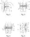
- shows two components of the vacuum chamber of a degassing unit provided with one electromagnet and one magnetic interaction means arranged at a surface of a flange of a first and a second component respectively, comprising an optional cooling system;
- Fig. 3
- shows two components of the vacuum chamber of a degassing unit provided with a plurality of electromagnets and a plurality of magnetic interaction means arranged at a surface of a flange of a first and a second component respectively;
- Fig. 4
- shows two components of the vacuum chamber of a degassing unit provided with one electromagnet and one magnetic interaction means, both arranged around the circumference of a first and a second component respectively and comprising an optional cooling system;
- Fig. 5
- shows two components of the vacuum chamber of a degassing unit provided with two electromagnets and two magnetic interaction means, arranged at recesses provided on the outer surface of the shell of a first and a second component respectively.
-
Fig. 1 shows adegassing unit 1 having avacuum chamber 2 comprising a gasduct X, an upper vessel Y and a lower vessel Z, which can each be considered asfirst components 21 orsecond components 22 of thevacuum chamber 2. Thedegassing unit 1 also comprises a vacuum generation system W, e.g., a steam jet pump system. The components of thevacuum chamber 2 might comprise an outer surface 9 and arefractory lining 8. - The
degassing unit 1 can be used for Ruhrstahl-Heraeus (RH) or a Dortmund Hoerder (DH) degassing treatment. - The lower vessel Z has an opening Z1 on its upper side and also smaller openings on the lower side embodied as snorkels Z2. The upper side is defined for an orientation of the lower vessel Z during normal operation. In normal operation said snorkels Z2 are immersed in a ladle V containing molten metal U, e.g., molten steel.
- The upper vessel Y has an opening Y1 on its lower side as well as an opening Y2 on its upper side. The lower and upper sides are defined for an orientation of the upper vessel Y during normal operation. The upper vessel Y also has an optional alloy chute Y3 to add alloys to the molten metal to fine-tune the molten metal chemistry, and an optional burner opening Y4 that enables fuel and oxygen to be blown into the
vacuum chamber 2, retaining the heat within thevacuum chamber 2, and reducing adhesion of metals within thevacuum chamber 2. Of course, the alloy chute Y3 and/or burner opening Y4 are designed to maintain the vacuum inside thevacuum chamber 2. - The gas duct X has an opening X1 to be connected to the upper opening Y2 of the upper vessel Y during assembling of the
vacuum chamber 2 of thedegassing unit 1. The opening Z1 of the lower vessel Z is to be connected to the lower opening Y1 of the upper vessel Y during assembling of thevacuum chamber 2 of thedegassing unit 1. - The
vacuum chamber 2 as depicted comprises a hull which defines a more or less closed inner space to be sealed. The hull here is assembled by connecting the opening X1 of the gas duct X to the upper opening Y2 of the upper vessel Y and by connecting the opening Z1 of the lower vessel to the lower opening Y1 of the upper vessel such that the inner space of the vacuum chamber is defined by the gas duct X, the upper vessel Y and the lower vessel Z. - This disclosure in general describes the connection of the opening of a
first component 21 and the opening of asecond component 22 of avacuum chamber 2 of adegassing unit 1, said connection ensuring sealing of saidvacuum chamber 2. - Therefore, the lower vessel Z can be considered as
first component 21 connected to the upper vessel Y considered assecond component 22 or the upper vessel Y can be considered asfirst component 21 connected to the lower vessel Z considered assecond component 22. Also, the upper vessel Y can be considered asfirst component 21 connected to the gas duct X considered assecond component 22 or the gas duct X can be considered asfirst component 21 connected to the upper vessel Y considered assecond component 22. - An
electromagnet 3 at the opening of thefirst component 21 and a magnetic interaction means 4 at the opening of thesecond component 22 are provided. Theelectromagnet 3 is configured to generate a magnetic field H interacting with the magnetic interaction means 4 such that an attracting force F is generated between theelectromagnet 3 and the magnetic interaction means 4, and thus between the opening of thefirst component 21 and the opening of thesecond component 22 to seal thevacuum chamber 2. The magnetic interaction means 4 can comprise at least one of: a permanent magnet, a further electromagnet, ferromagnetic material - In
Fig. 2 by way of example the gas duct X is considered to be thefirst component 21, wherein the upper vessel Y is considered to be thesecond component 22. Anelectromagnet 3 is arranged at the opening X1 of thefirst component 21 and a magnetic interaction means 4 is arranged at the opening Y2 of thesecond component 22. In the embodiment shown inFig. 2 aflange 6 is provided at thefirst component 21 encircling the circumference of thefirst component 21 at the opening X1 facing the opening Y2 of thesecond component 22 and theelectromagnet 3 is arranged at a surface of theflange 6 of thefirst component 21 opposing the opening Y2 of thesecond component 22. The embodiment shown inFig. 2 also shows aflange 7 at thesecond component 22 encircling the circumference of thesecond component 22 at the opening Y2 facing the opening X1 of thefirst component 21 and the magnetic interaction means 4 is arranged at a surface of theflange 7 of thesecond component 22 opposing the opening X1 of thefirst component 21. Anoptional cooling system 10 is arranged at thefirst component 21 next to theelectromagnet 3, to avoid that the temperature of the ferromagnetic material of theelectromagnet 3 exceeds a maximum temperature, e.g., its Curie temperature, where the ferromagnetic properties of the material vanish. - Activating the
electromagnet 3 generates a magnetic field H which interacts with the magnetic interaction means 4. Due to this interaction an attracting magnetic force F is generated between theelectromagnet 3 and the magnetic interaction means 4 and thus between the opening X1 of the first component 21 (here the gas duct X) and the opening Y2 of the second component 22 (here the upper vessel Y) to seal thevacuum chamber 2. - In
Fig. 3 by way of example the upper vessel Y is considered to be thefirst component 21, wherein the lower vessel Z is considered to be thesecond component 22. Here a plurality ofelectromagnets 3 is arranged at a surface of theflange 6 at the opening Y1 of the first component 21 (the upper vessel Y) opposing the opening Z1 of the second component 22 (the lower vessel Z), wherein a plurality of magnetic interaction means 4 is arranged at a surface of theflange 7 at the opening Z1 of the second component 22 (the lower vessel Z) opposing the opening Y1 of the first component 21 (the upper vessel Y). - Activating the
electromagnets 3 generate a magnetic field H which interacts with the magnetic interaction means 4. Due to this interaction an attracting magnetic force F is generated between theelectromagnets 3 and the magnetic interaction means 4 and thus between the opening Y1 of the first component 21 (here the upper vessel Y) and the opening Z1 of the second component 22 (here the lower vessel Z) to seal thevacuum chamber 2. InFig. 3 , for easier depiction, the magnetic field generated by only one of theelectromagnets 3 is indicated. - In
Fig. 4 like inFig. 3 the upper vessel Y is considered to be thefirst component 21, wherein the lower vessel Z is considered to be thesecond component 22. Here anelectromagnet 3 is arranged around the circumference of the first component 21 (the upper vessel Y) and along the surface of theflange 6 at the opening Y1 of the first component 21 (the upper vessel Y) opposing the opening Z1 of thesecond component 22, wherein the magnetic interaction means 4 is arranged around the circumference of the second component 22 (the lower vessel Z) and along the surface of theflange 7 at the opening Z1 of the second component 22 (the lower vessel Z) opposing the opening Y1 of thefirst component 21. Anoptional cooling system 10 is arranged at the second component 22 (the lower vessel Z) next to the magnetic interaction means 4, to avoid that the temperature of the ferromagnetic material of the magnetic interaction means 4 exceeds a maximum temperature, e.g., its Curie temperature, where the ferromagnetic properties of the material vanish. - Activating the
electromagnet 3 generates a magnetic field H which interacts with the magnetic interaction means 4. Due to this interaction an attracting magnetic force F is generated between theelectromagnet 3 and the magnetic interaction means 4 and thus between the opening Y1 of the first component 21 (here the upper vessel Y) and the opening Z1 of the second component 22 (here the lower vessel Z) to seal thevacuum chamber 2. - The
electromagnet 3 can be integral part of thefirst component 21 and/or the magnetic interaction means 4 can be integral part of thesecond component 22. - When establishing a connection of the gas duct X and the upper vessel Y by way of an
electromagnet 3 and a magnetic interaction means 4 (i.e., considering the gas duct X asfirst component 21 and the upper vessel Y assecond component 22 or the other way around), e.g., according to the embodiment shown inFig. 2 , the upper vessel Y and the lower vessel Z can also be connected by way of anelectromagnet 3 and a magnetic interaction means 4, e.g., according to the embodiment shown inFig. 3 or Fig. 4 , or by any other means suitable. - Likewise, when using a connection of the upper vessel Y and the lower vessel Z by way of an
electromagnet 3 and a magnetic interaction means 4 (i.e., considering the upper vessel Y asfirst component 21 and the lower vessel Z assecond component 22 or the other way around), e.g., according to the embodiment shown inFig. 3 or Fig. 4 , the upper vessel Y and the gas duct X can also be connected by way of anelectromagnet 3 and a magnetic interaction means 4, e.g., according to the embodiment shown inFig. 2 , or by any other means suitable. - In
Fig. 5 the upper vessel Y is considered to be thefirst component 21, wherein the lower vessel Z is considered to be thesecond component 22. Here anelectromagnet 3 is arranged at arecess 11 provided on the outer surface of the shell of the first component 21 (the upper vessel Y), wherein a magnetic interaction means 4 is arranged at arecess 11 provided on the outer surface of the shell of the second component 22 (the lower vessel Z). Activating theelectromagnet 3 generates a magnetic field H which interacts with the magnetic interaction means 4. Due to this interaction an attracting magnetic force F is generated between theelectromagnet 3 and the magnetic interaction means 4 and thus between the opening Y1 of the first component 21 (here the upper vessel Y) and the opening Z1 of the second component 22 (here the lower vessel Z) to seal thevacuum chamber 2. InFig. 5 , for easier depiction, only one of the magnetic fields generated by theelectromagnets 3 is indicated.
Claims (15)
- Method for sealing a vacuum chamber (2) of a degassing unit (1) for molten metal, the vacuum chamber (2) comprising a first component (21) having an opening and a second component (22) having an opening, the openings of the first and second component being connected to each other, characterized in that an electromagnet (3), which is connected to or part of the first component (21), is activated to generate a magnetic field (H) interacting with a magnetic interaction means (4), which is connected to or part of the second component (22), such that an attracting force (F) is generated between the electromagnet (3) and the magnetic interaction means (4), and thus between the opening of the first component (21) and the opening of the second component (22) to seal the vacuum chamber (2).
- Vacuum chamber (2) for a degassing unit (1) for molten metal, comprising a first component (21) having an opening and a second component (22) having an opening, the openings of the first and second component being connected to each other, characterized in that the vacuum chamber (2) comprises an electromagnet (3) being connected to or part of the first component (21) and a magnetic interaction means (4) being connected to or part of the second component (22), wherein the electromagnet (3) is configured to generate a magnetic field (H) interacting with the magnetic interaction means (4) such that an attracting force (F) is generated between the electromagnet (3) and the magnetic interaction means (4), and thus between the opening of the first component (21) and the opening of the second component (22) to seal the vacuum chamber (2).
- Vacuum chamber (2) according to claim 2, characterized in that the magnetic interaction means (4) comprises at least one of: a permanent magnet, a further electromagnet, ferromagnetic material.
- Vacuum chamber (2) according to claim 2 or 3, characterized in that the first component (21) is a flue gas duct (X), and the second component (22) is an upper vessel (Y), or the first component (21) is an upper vessel (Y), and the second component (22) is a flue gas duct (X).
- Vacuum chamber (2) according to claim 2 or 3, characterized in that the first component (21) is an upper vessel (Y), and the second component (22) is a lower vessel (Z), or the first component (21) is a lower vessel (Z), and the second component (22) is an upper vessel (Y).
- Vacuum chamber (2) according to any one of claims 2 to 5, characterized in that the electromagnet (3) is arranged at the opening of the first component (21).
- Vacuum chamber (2) according to claim 6, characterized in that a flange (6) is provided at the opening of the first component (21) and in that the electromagnet (3) is arranged at said flange (6) of the first component (21), preferably at a surface of the flange (6) of the first component (21) opposing the opening of the second component (22).
- Vacuum chamber (2) according to any one of claims 2 to 7, characterized in that the electromagnet (3) is arranged with its windings around the circumference of the first component (21).
- Vacuum chamber (2) according to any one of claims 2 to 8, characterized in that the magnetic interaction means (4) is arranged at the opening of the second component (22)
- Vacuum chamber (2) according to claim 9, characterized in that a flange (7) is provided at the opening of the second component (22) and in that the magnetic interaction means (4) is arranged at said flange (7) of the second component (22).
- Vacuum chamber (2) according to claim 10, characterized in that the magnetic interaction means (4) is arranged at a surface of the flange (7) of the second component (22) opposing the opening of the first component (21).
- Vacuum chamber (2) according to any one of claims 2 to 11, characterized in that the magnetic interaction means (4) is arranged around the circumference of the second component (22).
- Vacuum chamber (2) according to any one of claims 2 to 12, characterized in that a plurality of electromagnets (3) is provided at the first component (21), configured to generate a magnetic field (H) interacting with the magnetic interaction means (4) and/or further magnetic interaction means (4), being connected to or part of the second component (22).
- Vacuum chamber (2) according to any one of claims 2 to 13, characterized in that a cooling system (10) at the first component (21) and/or at the second component (22) is provided.
- Degassing unit (1) for molten metal, preferably a Ruhrstahl-Heraeus or a Dortmund Hoerder vacuum treatment degassing unit, comprising a vacuum chamber (2) according to any one of claims 2 to 14.
Priority Applications (2)
| Application Number | Priority Date | Filing Date | Title |
|---|---|---|---|
| EP22206562.5A EP4368734B1 (en) | 2022-11-10 | 2022-11-10 | Vacuum chamber for a degassing unit for molten metal and method for sealing of a vacuum chamber |
| PCT/EP2023/081330 WO2024100206A1 (en) | 2022-11-10 | 2023-11-09 | Vacuum chamber for a degassing unit for molten metal and method for sealing of a vacuum chamber |
Applications Claiming Priority (1)
| Application Number | Priority Date | Filing Date | Title |
|---|---|---|---|
| EP22206562.5A EP4368734B1 (en) | 2022-11-10 | 2022-11-10 | Vacuum chamber for a degassing unit for molten metal and method for sealing of a vacuum chamber |
Publications (3)
| Publication Number | Publication Date |
|---|---|
| EP4368734A1 true EP4368734A1 (en) | 2024-05-15 |
| EP4368734B1 EP4368734B1 (en) | 2026-01-28 |
| EP4368734C0 EP4368734C0 (en) | 2026-01-28 |
Family
ID=84387904
Family Applications (1)
| Application Number | Title | Priority Date | Filing Date |
|---|---|---|---|
| EP22206562.5A Active EP4368734B1 (en) | 2022-11-10 | 2022-11-10 | Vacuum chamber for a degassing unit for molten metal and method for sealing of a vacuum chamber |
Country Status (2)
| Country | Link |
|---|---|
| EP (1) | EP4368734B1 (en) |
| WO (1) | WO2024100206A1 (en) |
Citations (3)
| Publication number | Priority date | Publication date | Assignee | Title |
|---|---|---|---|---|
| JPH11293329A (en) * | 1998-04-07 | 1999-10-26 | Nkk Corp | Method for producing ultra-low carbon Si-killed steel with excellent cleanliness |
| JP5026694B2 (en) * | 2005-12-07 | 2012-09-12 | 株式会社神戸製鋼所 | RH degassing equipment |
| JP5103942B2 (en) * | 2007-02-28 | 2012-12-19 | Jfeスチール株式会社 | Ascending side dip tube of RH vacuum degasser |
-
2022
- 2022-11-10 EP EP22206562.5A patent/EP4368734B1/en active Active
-
2023
- 2023-11-09 WO PCT/EP2023/081330 patent/WO2024100206A1/en not_active Ceased
Patent Citations (3)
| Publication number | Priority date | Publication date | Assignee | Title |
|---|---|---|---|---|
| JPH11293329A (en) * | 1998-04-07 | 1999-10-26 | Nkk Corp | Method for producing ultra-low carbon Si-killed steel with excellent cleanliness |
| JP5026694B2 (en) * | 2005-12-07 | 2012-09-12 | 株式会社神戸製鋼所 | RH degassing equipment |
| JP5103942B2 (en) * | 2007-02-28 | 2012-12-19 | Jfeスチール株式会社 | Ascending side dip tube of RH vacuum degasser |
Also Published As
| Publication number | Publication date |
|---|---|
| EP4368734B1 (en) | 2026-01-28 |
| EP4368734C0 (en) | 2026-01-28 |
| WO2024100206A1 (en) | 2024-05-16 |
Similar Documents
| Publication | Publication Date | Title |
|---|---|---|
| JP2009125810A (en) | Centrifugal casting system for highly active titanium metal | |
| CN101829770A (en) | System for centrifugally casting high-activity titanium | |
| EP4368734B1 (en) | Vacuum chamber for a degassing unit for molten metal and method for sealing of a vacuum chamber | |
| CA2267071C (en) | Panelized spray-cooled furnace roof | |
| KR20190003589A (en) | Method for operating a device for supplying liquid metal to an evaporator | |
| CN107532849B (en) | Electric induction melting and holding furnaces for reactive metals and alloys | |
| JP2011042850A (en) | Dezincification apparatus and dezincification method | |
| US7967057B2 (en) | Induction melting apparatus employing halide type crucible, process for producing the crucible, method of induction melting, and process for producing ingot of ultrahigh-purity Fe-, Ni-, or Co-based alloy material | |
| US4583230A (en) | Apparatus for induction heating of molten metal | |
| KR940003253B1 (en) | Apparatus for heating molten metal in a ladle | |
| JP7315218B2 (en) | Molten metal driving device and molten metal driving method | |
| US8790570B2 (en) | Movable device for injecting oxygen and other materials into electric arc furnace | |
| US7214272B2 (en) | Device for coating metal bars by hot dipping | |
| JP2005153002A (en) | Rotary hot water casting equipment | |
| WO1997016051A1 (en) | Electric heating element | |
| JP2000258067A (en) | Floating melting apparatus and casting method | |
| JP7647787B2 (en) | Vacuum degassing device and method for preventing deformation of lower tank | |
| JPH0780632A (en) | Molten metal holding furnace | |
| JPS6013014A (en) | Ladle refining equipment | |
| JP2003227687A (en) | Metal melting equipment | |
| JP2006029674A (en) | Refining apparatus and refining method | |
| JP2006214647A (en) | Water-cooled lid for ladle refining and refining treatment method | |
| US20180080094A1 (en) | Mounting enclosure with externally removable insert panel | |
| JPWO2018190283A1 (en) | Water cooled lance | |
| JPH0941030A (en) | Vacuum ladle lid |
Legal Events
| Date | Code | Title | Description |
|---|---|---|---|
| PUAI | Public reference made under article 153(3) epc to a published international application that has entered the european phase |
Free format text: ORIGINAL CODE: 0009012 |
|
| STAA | Information on the status of an ep patent application or granted ep patent |
Free format text: STATUS: THE APPLICATION HAS BEEN PUBLISHED |
|
| AK | Designated contracting states |
Kind code of ref document: A1 Designated state(s): AL AT BE BG CH CY CZ DE DK EE ES FI FR GB GR HR HU IE IS IT LI LT LU LV MC ME MK MT NL NO PL PT RO RS SE SI SK SM TR |
|
| STAA | Information on the status of an ep patent application or granted ep patent |
Free format text: STATUS: REQUEST FOR EXAMINATION WAS MADE |
|
| 17P | Request for examination filed |
Effective date: 20241115 |
|
| RBV | Designated contracting states (corrected) |
Designated state(s): AL AT BE BG CH CY CZ DE DK EE ES FI FR GB GR HR HU IE IS IT LI LT LU LV MC ME MK MT NL NO PL PT RO RS SE SI SK SM TR |
|
| GRAP | Despatch of communication of intention to grant a patent |
Free format text: ORIGINAL CODE: EPIDOSNIGR1 |
|
| STAA | Information on the status of an ep patent application or granted ep patent |
Free format text: STATUS: GRANT OF PATENT IS INTENDED |
|
| GRAS | Grant fee paid |
Free format text: ORIGINAL CODE: EPIDOSNIGR3 |
|
| INTG | Intention to grant announced |
Effective date: 20251121 |
|
| GRAA | (expected) grant |
Free format text: ORIGINAL CODE: 0009210 |
|
| STAA | Information on the status of an ep patent application or granted ep patent |
Free format text: STATUS: THE PATENT HAS BEEN GRANTED |
|
| AK | Designated contracting states |
Kind code of ref document: B1 Designated state(s): AL AT BE BG CH CY CZ DE DK EE ES FI FR GB GR HR HU IE IS IT LI LT LU LV MC ME MK MT NL NO PL PT RO RS SE SI SK SM TR |
|
| REG | Reference to a national code |
Ref country code: CH Ref legal event code: F10 Free format text: ST27 STATUS EVENT CODE: U-0-0-F10-F00 (AS PROVIDED BY THE NATIONAL OFFICE) Effective date: 20260128 Ref country code: GB Ref legal event code: FG4D |
|
| REG | Reference to a national code |
Ref country code: IE Ref legal event code: FG4D |
|
| U01 | Request for unitary effect filed |
Effective date: 20260128 |
|
| U07 | Unitary effect registered |
Designated state(s): AT BE BG DE DK EE FI FR IT LT LU LV MT NL PT RO SE SI Effective date: 20260203 |