EP4368542A1 - Shifting, re-orienting, organizing, and/or routing objects including parcels and packages - Google Patents
Shifting, re-orienting, organizing, and/or routing objects including parcels and packages Download PDFInfo
- Publication number
- EP4368542A1 EP4368542A1 EP23200078.6A EP23200078A EP4368542A1 EP 4368542 A1 EP4368542 A1 EP 4368542A1 EP 23200078 A EP23200078 A EP 23200078A EP 4368542 A1 EP4368542 A1 EP 4368542A1
- Authority
- EP
- European Patent Office
- Prior art keywords
- pivoting
- extension
- bin
- orienting
- objects
- Prior art date
- Legal status (The legal status is an assumption and is not a legal conclusion. Google has not performed a legal analysis and makes no representation as to the accuracy of the status listed.)
- Granted
Links
Images







Classifications
-
- B—PERFORMING OPERATIONS; TRANSPORTING
- B65—CONVEYING; PACKING; STORING; HANDLING THIN OR FILAMENTARY MATERIAL
- B65G—TRANSPORT OR STORAGE DEVICES, e.g. CONVEYORS FOR LOADING OR TIPPING, SHOP CONVEYOR SYSTEMS OR PNEUMATIC TUBE CONVEYORS
- B65G47/00—Article or material-handling devices associated with conveyors; Methods employing such devices
- B65G47/22—Devices influencing the relative position or the attitude of articles during transit by conveyors
- B65G47/24—Devices influencing the relative position or the attitude of articles during transit by conveyors orientating the articles
-
- B—PERFORMING OPERATIONS; TRANSPORTING
- B65—CONVEYING; PACKING; STORING; HANDLING THIN OR FILAMENTARY MATERIAL
- B65G—TRANSPORT OR STORAGE DEVICES, e.g. CONVEYORS FOR LOADING OR TIPPING, SHOP CONVEYOR SYSTEMS OR PNEUMATIC TUBE CONVEYORS
- B65G35/00—Mechanical conveyors not otherwise provided for
-
- B—PERFORMING OPERATIONS; TRANSPORTING
- B07—SEPARATING SOLIDS FROM SOLIDS; SORTING
- B07C—POSTAL SORTING; SORTING INDIVIDUAL ARTICLES, OR BULK MATERIAL FIT TO BE SORTED PIECE-MEAL, e.g. BY PICKING
- B07C3/00—Sorting according to destination
- B07C3/02—Apparatus characterised by the means used for distribution
- B07C3/08—Apparatus characterised by the means used for distribution using arrangements of conveyors
-
- B—PERFORMING OPERATIONS; TRANSPORTING
- B65—CONVEYING; PACKING; STORING; HANDLING THIN OR FILAMENTARY MATERIAL
- B65D—CONTAINERS FOR STORAGE OR TRANSPORT OF ARTICLES OR MATERIALS, e.g. BAGS, BARRELS, BOTTLES, BOXES, CANS, CARTONS, CRATES, DRUMS, JARS, TANKS, HOPPERS, FORWARDING CONTAINERS; ACCESSORIES, CLOSURES, OR FITTINGS THEREFOR; PACKAGING ELEMENTS; PACKAGES
- B65D88/00—Large containers
- B65D88/54—Large containers characterised by means facilitating filling or emptying
-
- B—PERFORMING OPERATIONS; TRANSPORTING
- B65—CONVEYING; PACKING; STORING; HANDLING THIN OR FILAMENTARY MATERIAL
- B65D—CONTAINERS FOR STORAGE OR TRANSPORT OF ARTICLES OR MATERIALS, e.g. BAGS, BARRELS, BOTTLES, BOXES, CANS, CARTONS, CRATES, DRUMS, JARS, TANKS, HOPPERS, FORWARDING CONTAINERS; ACCESSORIES, CLOSURES, OR FITTINGS THEREFOR; PACKAGING ELEMENTS; PACKAGES
- B65D90/00—Component parts, details or accessories for large containers
- B65D90/0033—Lifting means forming part of the container
-
- B—PERFORMING OPERATIONS; TRANSPORTING
- B65—CONVEYING; PACKING; STORING; HANDLING THIN OR FILAMENTARY MATERIAL
- B65D—CONTAINERS FOR STORAGE OR TRANSPORT OF ARTICLES OR MATERIALS, e.g. BAGS, BARRELS, BOTTLES, BOXES, CANS, CARTONS, CRATES, DRUMS, JARS, TANKS, HOPPERS, FORWARDING CONTAINERS; ACCESSORIES, CLOSURES, OR FITTINGS THEREFOR; PACKAGING ELEMENTS; PACKAGES
- B65D90/00—Component parts, details or accessories for large containers
- B65D90/008—Doors for containers, e.g. ISO-containers
-
- B—PERFORMING OPERATIONS; TRANSPORTING
- B65—CONVEYING; PACKING; STORING; HANDLING THIN OR FILAMENTARY MATERIAL
- B65D—CONTAINERS FOR STORAGE OR TRANSPORT OF ARTICLES OR MATERIALS, e.g. BAGS, BARRELS, BOTTLES, BOXES, CANS, CARTONS, CRATES, DRUMS, JARS, TANKS, HOPPERS, FORWARDING CONTAINERS; ACCESSORIES, CLOSURES, OR FITTINGS THEREFOR; PACKAGING ELEMENTS; PACKAGES
- B65D90/00—Component parts, details or accessories for large containers
- B65D90/02—Wall construction
-
- B—PERFORMING OPERATIONS; TRANSPORTING
- B65—CONVEYING; PACKING; STORING; HANDLING THIN OR FILAMENTARY MATERIAL
- B65D—CONTAINERS FOR STORAGE OR TRANSPORT OF ARTICLES OR MATERIALS, e.g. BAGS, BARRELS, BOTTLES, BOXES, CANS, CARTONS, CRATES, DRUMS, JARS, TANKS, HOPPERS, FORWARDING CONTAINERS; ACCESSORIES, CLOSURES, OR FITTINGS THEREFOR; PACKAGING ELEMENTS; PACKAGES
- B65D90/00—Component parts, details or accessories for large containers
- B65D90/12—Supports
-
- B—PERFORMING OPERATIONS; TRANSPORTING
- B65—CONVEYING; PACKING; STORING; HANDLING THIN OR FILAMENTARY MATERIAL
- B65G—TRANSPORT OR STORAGE DEVICES, e.g. CONVEYORS FOR LOADING OR TIPPING, SHOP CONVEYOR SYSTEMS OR PNEUMATIC TUBE CONVEYORS
- B65G47/00—Article or material-handling devices associated with conveyors; Methods employing such devices
- B65G47/22—Devices influencing the relative position or the attitude of articles during transit by conveyors
- B65G47/24—Devices influencing the relative position or the attitude of articles during transit by conveyors orientating the articles
- B65G47/248—Devices influencing the relative position or the attitude of articles during transit by conveyors orientating the articles by turning over or inverting them
-
- B—PERFORMING OPERATIONS; TRANSPORTING
- B65—CONVEYING; PACKING; STORING; HANDLING THIN OR FILAMENTARY MATERIAL
- B65G—TRANSPORT OR STORAGE DEVICES, e.g. CONVEYORS FOR LOADING OR TIPPING, SHOP CONVEYOR SYSTEMS OR PNEUMATIC TUBE CONVEYORS
- B65G47/00—Article or material-handling devices associated with conveyors; Methods employing such devices
- B65G47/22—Devices influencing the relative position or the attitude of articles during transit by conveyors
- B65G47/24—Devices influencing the relative position or the attitude of articles during transit by conveyors orientating the articles
- B65G47/248—Devices influencing the relative position or the attitude of articles during transit by conveyors orientating the articles by turning over or inverting them
- B65G47/252—Devices influencing the relative position or the attitude of articles during transit by conveyors orientating the articles by turning over or inverting them about an axis substantially perpendicular to the conveying direction
-
- B—PERFORMING OPERATIONS; TRANSPORTING
- B65—CONVEYING; PACKING; STORING; HANDLING THIN OR FILAMENTARY MATERIAL
- B65G—TRANSPORT OR STORAGE DEVICES, e.g. CONVEYORS FOR LOADING OR TIPPING, SHOP CONVEYOR SYSTEMS OR PNEUMATIC TUBE CONVEYORS
- B65G47/00—Article or material-handling devices associated with conveyors; Methods employing such devices
- B65G47/34—Devices for discharging articles or materials from conveyor
- B65G47/38—Devices for discharging articles or materials from conveyor by dumping, tripping, or releasing load carriers
-
- B—PERFORMING OPERATIONS; TRANSPORTING
- B65—CONVEYING; PACKING; STORING; HANDLING THIN OR FILAMENTARY MATERIAL
- B65G—TRANSPORT OR STORAGE DEVICES, e.g. CONVEYORS FOR LOADING OR TIPPING, SHOP CONVEYOR SYSTEMS OR PNEUMATIC TUBE CONVEYORS
- B65G47/00—Article or material-handling devices associated with conveyors; Methods employing such devices
- B65G47/52—Devices for transferring articles or materials between conveyors i.e. discharging or feeding devices
-
- B—PERFORMING OPERATIONS; TRANSPORTING
- B65—CONVEYING; PACKING; STORING; HANDLING THIN OR FILAMENTARY MATERIAL
- B65G—TRANSPORT OR STORAGE DEVICES, e.g. CONVEYORS FOR LOADING OR TIPPING, SHOP CONVEYOR SYSTEMS OR PNEUMATIC TUBE CONVEYORS
- B65G47/00—Article or material-handling devices associated with conveyors; Methods employing such devices
- B65G47/52—Devices for transferring articles or materials between conveyors i.e. discharging or feeding devices
- B65G47/60—Devices for transferring articles or materials between conveyors i.e. discharging or feeding devices to or from conveyors of the suspended, e.g. trolley, type
- B65G47/61—Devices for transferring articles or materials between conveyors i.e. discharging or feeding devices to or from conveyors of the suspended, e.g. trolley, type for articles
-
- B—PERFORMING OPERATIONS; TRANSPORTING
- B65—CONVEYING; PACKING; STORING; HANDLING THIN OR FILAMENTARY MATERIAL
- B65G—TRANSPORT OR STORAGE DEVICES, e.g. CONVEYORS FOR LOADING OR TIPPING, SHOP CONVEYOR SYSTEMS OR PNEUMATIC TUBE CONVEYORS
- B65G65/00—Loading or unloading
-
- B—PERFORMING OPERATIONS; TRANSPORTING
- B65—CONVEYING; PACKING; STORING; HANDLING THIN OR FILAMENTARY MATERIAL
- B65G—TRANSPORT OR STORAGE DEVICES, e.g. CONVEYORS FOR LOADING OR TIPPING, SHOP CONVEYOR SYSTEMS OR PNEUMATIC TUBE CONVEYORS
- B65G47/00—Article or material-handling devices associated with conveyors; Methods employing such devices
- B65G47/22—Devices influencing the relative position or the attitude of articles during transit by conveyors
- B65G47/24—Devices influencing the relative position or the attitude of articles during transit by conveyors orientating the articles
- B65G47/244—Devices influencing the relative position or the attitude of articles during transit by conveyors orientating the articles by turning them about an axis substantially perpendicular to the conveying plane
Definitions
- the field relates to automated handling of objects.
- this disclosure describes, among other things, systems, methods, apparatuses, and technologies for shifting, orienting, organizing, and/or routing objects including parcels and packages, among other things. These embodiments may be implemented in a logistics network operation, among other instances.
- a system is provided that can shift and/or re-orient objects, e.g., based on their shape and/or dimensions, and then release the objects into transport receptacles for further shifting, organizing, and/or routing.
- an object-orienting mechanism is provided.
- the object-orienting mechanism can include a pivot-assembly, a plurality of pivoting-extensions, e.g., that can be independently rotated into different positions, and a plurality of actuators, e.g., that can shift the pivoting-extensions, e.g., at the direction of a control system.
- a bin for transporting objects is provided.
- the bin can include a base, at least one sidewall extending to an opening, and a releasing mechanism that is operable to support or release objects deposited into the bin.
- a container that can support objects is provided, and a container-flipping mechanism that can be used to displace objects from the container is provided.
- a process of re-orienting, re-positioning, and/or depositing objects is provided.
- objects can be re-oriented onto a side of shortest and/or smallest dimension, e.g., to allow for processing using a smallest available footprint, among other benefits.
- the embodiments described herein can support faster, more effective, and more space-efficient shifting and processing of objects, e.g., in a logistics network operation, among other benefits.
- this disclosure describes, among other things, embodiments that support and enable the shifting, re-orienting, organizing, and/or routing of objects, e.g., parcels and packages, e.g., in a logistics network operation, among other things.
- objects can be handled, processed, and/or transferred more efficiently through re-orienting the objects onto a side of shortest or smallest dimension. This can be used to reduce or limit the footprint of the objects, e.g., during storage and transfer, which can allow a greater number of objects to be processed and/or allow objects to be processed with greater efficiency.
- Different embodiments that support such efficient processing including object-orienting mechanisms, object-shifting mechanisms, storage bins, containers, and the like, are described in detail below in connection with accompanying FIGS. 1-23 .
- the subject matter of this disclosure may be provided as, at least in part, a method, a system, and/or a computer program product, among other things. Accordingly, certain aspects described herein may be hardware, software, or may be a combination of software and hardware. A computer program that includes computer-useable instructions embodied on one or more computer-readable media may also be used. The subject matter herein may further be implemented as hard-coded into the mechanical design of computing components and/or may be built into a system or components thereof used for shifting, re-orienting, organizing, and/or routing objects such as parcels and packages, e.g., such as boxes, containers, bags, pouches, carriers, totes, and the like.
- Computer-readable media may include volatile media, non-volatile media, removable media, and non-removable media, and may also include media readable by a database, a switch, and/or various other network devices. Network switches, routers, and related components are conventional in nature, as are methods of communicating with the same, and thus, further elaboration is not provided in this disclosure.
- computer-readable media may include computer storage media and/or non-transitory communications media.
- Computer storage media may include media implemented in any method or technology for storing information. Examples of stored information include computer-useable instructions, data structures, program modules, and/or other data representations.
- Computer storage media may include, but is not limited to, RAM, ROM, EEPROM, flash memory or other memory technology, CD-ROM, digital versatile discs (DVD), holographic media or other optical disc storage, magnetic cassettes, magnetic tape, magnetic disk storage, and other storage devices. These memory components may store data momentarily, temporarily, and/or permanently, and are not limited to the examples provided herein.
- FIG. 1 a block diagram of an example computing device 1 suitable for supporting and performing functions described herein is provided, in accordance with an embodiment of the present disclosure.
- computing device 1 might include multiple processors and/or multiple radios.
- the computing device 1 shown in FIG. 1 includes a bus 9 that may directly or indirectly connect different components together, e.g., such as memory 2, processor(s) 3, presentation component(s) 4 (if applicable), radio(s) 5, input/output (I/O) port(s) 6, input/output (I/O) component(s) 7, and/or power supply 8.
- bus 9 may directly or indirectly connect different components together, e.g., such as memory 2, processor(s) 3, presentation component(s) 4 (if applicable), radio(s) 5, input/output (I/O) port(s) 6, input/output (I/O) component(s) 7, and/or power supply 8.
- Memory 2 may take the form of the memory components described herein. Thus, further elaboration will not be provided here, but memory 2 may include any type of tangible medium that is capable of storing information, such as a database.
- a database may include any collection of records, data, and/or other information.
- memory 2 may include a set of computer-executable instructions that, when executed, facilitate various functions or steps associated with the subject matter described herein. These instructions will be referred to as "instructions" or an "application” for short.
- the processor 3 may actually be multiple processors that may receive instructions and process them accordingly.
- the presentation component 4 may include a display, a speaker, a screen, a portable digital device, and/or other components that can present information through visual, auditory, and/or other tactile cues (e.g., a display, a screen, a lamp, a light-emitting diode (LED), a graphical user interface (GUI), and/or a lighted keyboard).
- a display e.g., a display, a screen, a lamp, a light-emitting diode (LED), a graphical user interface (GUI), and/or a lighted keyboard.
- LED light-emitting diode
- GUI graphical user interface
- the radio 5 may facilitate communication with a network, and may additionally or alternatively facilitate other types of wireless communications, such as Wi-Fi, WiMAX, LTE, Bluetooth, and/or VoIP communications, among other possible communication protocols.
- the radio 5 may be configured to support multiple technologies, and/or multiple radios may be configured and utilized to support multiple technologies in the embodiments contemplated herein.
- the input/output (I/O) ports 6 may take a variety of forms.
- Example I/O ports may include a Universal Serial Bus ("USB") jack, a stereo jack, an infrared port, and/or other proprietary communications ports.
- the input/output (I/O) components 7 may include one or more keyboards, microphones, speakers, touchscreens, and/or any other item useable to directly or indirectly input data into the computing device 1.
- the power supply 8 may comprise batteries, generators, fuel cells, an electrical supply source and/or any other component that may act as a power source to supply power to computing device 1 and to any other components described herein.
- FIG. 2 a system 10 for shifting objects, e.g., the objects 12, is shown, in accordance with an embodiment of the present disclosure.
- the system 10 is represented in FIG. 2 as a collection of structures, mechanisms, and technologies that operate in coordination to shift, re-orient, store, organize, and/or route the objects 12 to different locations.
- the objects 12 can be boxes, containers, bags, pouches, carriers, totes, and the like.
- the system 10 can be used in a logistics network operation, among other possible uses.
- each object-supply mechanism 14 is a conveyor, or a series of conveyors, e.g., those that include one or more belts, rollers, actuators, and/or other components.
- the object-supply mechanisms 14 can be used to initially transfer the objects 12 through the system 10, e.g., transiting them towards object-orienting mechanisms 16.
- the object-orienting mechanisms 16 can be used to re-orient the objects 12 (if needed), e.g., into a desired orientation for loading into storage bins 18.
- the selected orientation can be such that the object 12 is resting or supported on its shortest or smallest dimensional side, among other possible orientations.
- the objects 12 can then be deposited into the bins 18, and then transferred around the system 10 along track(s) 20.
- the storage bins 18 are transferred through the system 10 along the track(s) 20 such that each storage bin 18 is eventually routed under at least one of the object-orienting mechanisms 16.
- This allows the objects 12 that are supplied by the object-supply mechanisms 14 to be engaged, re-oriented, and then released/deposited by the object-orienting mechanisms 16 into the storage bins 18 that are sequentially positioned under the object-orienting mechanisms 16.
- the storage bin 18 with the object 12 can be shifted along the track(s) 20 until the storage bin 18 is in position over a particular container 23, e.g., one associated with a downstream location of the object 12, and/or one associated with an ultimate destination of the object 12.
- the containers 23 can be supported and transferred along a track 22, and subsequently manipulated by additional mechanisms, e.g., a container-flipping mechanism that can transfer the objects 12 in the containers 23 to other parts of the system 10.
- additional mechanisms e.g., a container-flipping mechanism that can transfer the objects 12 in the containers 23 to other parts of the system 10.
- the displacement of the containers 23 can be facilitated using different mechanisms, e.g., linear actuators, pushers, and the like.
- the track 22 can be a passive track (e.g., having a series of passive rollers), a powered track (e.g., having a series of powered rollers or conveyors), or a combination thereof.
- the track 22 shown in FIG. 2 includes a series of rollers 24.
- control system 15 e.g., one that includes one or more computing devices, communication components, and/or supporting software applications.
- the object-orienting mechanism 26 includes an assembly of components that operate in coordination to shift and re-orient an object, e.g., a parcel, package, or other receptacle, into a different orientation. This re-orienting of objects can be performed in furtherance of routing the objects, e.g., towards a downstream and/or final location.
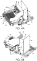
- FIGS. 4A and 4B show the object-orienting mechanism 26 with some components omitted for clarity, simplicity, and explanation.
- the object-orienting mechanism 26 includes a housing 28 and a frame 25 that supports the housing 28.
- the object-orienting mechanism 26 also includes a pivot-assembly 30.
- the pivot-assembly 30 provides a common axis of rotation for multiple elements including pivoting-extensions 46 and 48, described below.
- the object-orienting mechanism 26 also includes a plurality of actuators 32, 34, 36 that are operable to rotate different components of the object-orienting mechanism 26.
- the actuators 32, 34, 36 are rotational actuators, e.g., that are electrically, pneumatically, and/or hydraulically powered, that during operation can impart rotation to other components.
- the actuators 32, 34, 36 can be electrically-powered motors.
- the actuators 32, 34, 36 are coupled to belt-driven assemblies 38, 40, 42.
- the belt-driven assemblies 38, 40, 42 each include a belt extended over multiple rollers/wheels.
- the belt-driven assemblies 38, 40, 42 allow rotational motion generated by the actuators 32, 34, 36 to be transferred to other components of the object-orienting mechanism 26, e.g., such as the pivoting-extensions 46, 48.
- the actuators 32, 34, 36 can be connected to a control system 44 that can direct operation of the actuators 32, 34, 36.
- the control system 44 is depicted generically in FIG. 3 for explanation purposes, but can include computing components, communication components, software applications, and/or other technologies that support its operation.
- the control system 44 can be configured to operate the actuators 32, 34, 36 independently, and/or in coordination, e.g., at least partially together.
- the object-orienting mechanism 26 includes a pivoting-extension 46, a pivoting-extension 48, and a shifting mechanism 50.
- the pivoting-extension 46 is rotatably coupled to the pivot-assembly 30.
- the pivoting-extension 46 is also coupled to the actuator 32 through the belt-driven assembly 38.
- operation of the actuator 32 translates the corresponding belt-driven assembly 38 which rotates the pivoting-extension 46 to different positions on the pivot-assembly 30.
- the translation of the pivoting-extension 46 to different rotational positions is guided by a support element 58 that shifts generally within a pair of tracks 54, 56 located on opposite sides of the housing 28.
- the pivoting-extension 48 is also rotatably coupled to the pivot-assembly 30, and similarly is coupled to the actuator 34.
- operation of the actuator 34 translates the corresponding belt-driven assembly 40, which rotates the pivoting-extension 48 into different rotational positions on the pivot-assembly 30.
- the rotational force from the actuator 34 may be imparted directly to the pivoting-extension 48, or may be imparted indirectly to the pivoting-extension 48, e.g., through use of the belt-driven assembly 40.
- the inclusion of the separate actuators 32, 34 allows the pivoting-extensions 46, 48 to be rotated independently, or in unison, e.g., dependent on the operation being performed.
- the different geometries of the pivoting-extensions 46, 48 can allow for different lengths of support to be provided using the pivot-assembly 30.
- the pivoting-extension 46 may be at least twice the length (measured outward from the pivot-assembly 30) of the pivoting-extension 48.
- This differential in length can be based on the dimensions of objects being handled by the object-orienting mechanism 26, and has been demonstrated to facilitate the orienting of objects, e.g., parcels and packages, onto their shortest and/or smallest dimensional side, among other benefits.
- the pivoting-extension 46 includes a plurality of spaced-apart fingers 60 (only some of which are identified for clarity).
- the pivoting-extension 48 includes a plurality of spaced-apart fingers 62 (only some of which are identified for clarity).
- the pivoting-extensions 46, 48 are each able to rotate about the pivot-assembly 30, i.e., about a common axis of rotation, such that the fingers 60 can shift between the fingers 62, and vice-versa.
- the axial-spacing and positioning of the fingers 60 across the pivot-assembly 30 and the axial-spacing and positioning of the fingers 62 across the pivot-assembly 30 is such that the pivoting-extensions 46, 48 can rotate into planar alignment (e.g., as shown in FIG. 3 ) with the fingers 60, 62 forming an interposed, alternating sequence in the same plane.
- the fingers 60, 62 are offset axially along the pivot-assembly 30 so that rotation of the fingers 60, 62 into a common plane is possible without the fingers 60, 62 directly contacting, or blocking, each other. This facilitates rotation of the pivoting-extensions 46, 48 to form different geometries, e.g., suitable for holding, rotating, and/or releasing objects, as discussed further in connection with FIGS. 5-10 .
- the shifting mechanism 50 includes a plurality of spaced-apart transfer mechanisms 52 (only some of which are identified for clarity) that are arranged in spaced-apart relation and in a substantially parallel configuration.
- the transfer mechanisms 52 can be operated to shift objects towards the pivoting-extensions 46, 48, and onto the pivoting-extensions 46, 48 when the pivoting-extensions 46, 48 are in planar alignment with the transfer mechanisms 52 of the shifting mechanism 50, e.g., as shown in FIG. 3 .
- the transfer mechanisms 52 each include a belt-driven assembly, e.g., one that includes a belt/cable and a plurality of rollers, which can be rotated by the actuator 36 to translate objects supported on the transfer mechanisms 52.
- the fingers 60 of the pivoting-extension 46 can be rotated about the pivot-assembly 30 substantially into planar alignment with the transfer mechanisms 52, e.g., such that the fingers 60 are located generally between the transfer mechanisms 52, generally aligned along the same plane, e.g., as shown in FIG. 3 .
- the actuator 36 associated with the shifting mechanism 52 can then be operated to shift an object supported on the transfer mechanisms 52 onto the fingers 60 of the pivoting-extension 46.
- the pivoting-extension 46 can be rotated so that the fingers 60 lift the object into another position/orientation, e.g., in conjunction with the pivoting-extension 48.
- This shifting process is further described in connection with FIGS. 5-11 .
- the object-orienting mechanism 26 includes a chute 64.
- the chute 64 is defined at least partially by the housing 28, and is designed to align with an opening in a storage receptacle positioned below the object-orienting mechanism 26.
- FIG. 4A a process of shifting and re-orienting an object 68 (shown in FIG. 4A ) using the object-orienting mechanism 26 will be described.
- the object 68 is transferred along the shifting mechanism 50, onto the pivoting-extension 46, and then the object 68 is lifted by the pivoting-extensions 46, 48 and rotated into a different orientation (as shown in FIGS.
- positioning an object e.g., such as the object 68, on its shortest and/or smallest dimension side can allow for subsequent processing, e.g., shifting, organizing, and/or routing, of objects at a higher density (due to the smaller footprint occupied by the objects), and/or at a higher density particularly if a consistent selection of object sizes is used, e.g., as often is the case in a logistics network operation that transfers parcels, packages, and other transport receptacles.
- FIG. 5 shows the object-orienting mechanism 26 operated so that the pivoting-extension 46 is shifted, i.e., rotated, generally upward, and away from the shifting mechanism 50.
- the pivoting-extension 48 has been rotated independently of the pivoting-extension 46, so that the pivoting-extension 46 and fingers 60 thereof and the pivoting-extension 48 and fingers 62 thereof are positioned approximately perpendicular, or orthogonal, to each other.
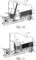
- FIGS. 6-11 the object-orienting mechanism 26 is shown in a sequence of different configurations, i.e., being used to shift, re-orient, and then deposit an object, in accordance with an embodiment of the present disclosure.
- FIGS. 6-11 look into the object-orienting mechanism 26 generally from one side with the housing 28 omitted for clarity, simplicity, and explanation.
- an object 68 is shown being transferred along the shifting mechanism 50 such that the object 68 is shifted onto the fingers 60 of the pivoting-extension 46.
- the pivoting-extension 48 has been rotated on the pivot-assembly 30 so that the pivoting-extensions 46, 48 and the fingers 60, 62 thereof generally form the cradle 66 that supports the object 68.
- the pivoting-extension 46 and/or the pivoting-extension 48 can be rotated independently using their respective actuators 32, 34.
- FIG. 7 the object-orienting mechanism 26 is again shown, but in a different configuration.
- the pivoting-extension 46 and the pivoting-extension 48 have been rotated (e.g., independently) to form the approximately perpendicular configuration that provides the cradle 66 for the object 68, and also, the pivoting-extension 46 and the pivoting-extension 48 have been rotated (e.g., in unison) to shift the cradle 66 and the object 68 to a more upright rotational position.
- This upright position starts to support the object 68 on its shortest and/or smallest dimensional side, as shown in FIG. 7 , and is closer to alignment with the chute 64 that extends through a bottom of the object-orienting mechanism 26.
- the object-orienting mechanism 26 is again shown, but in a different configuration.
- the pivoting-extension 48 is rotated (e.g., independently) such that it is extended generally in an opposite-facing direction compared to the pivoting-extension 46.
- the pivoting-extensions 46, 48 and fingers 60, 62 thereof are extending away from each other to form a generally planar configuration.
- This planar configuration allows gravity to shift the object 68 along the pivoting-extensions 46, 48 and toward the chute 64.
- This configuration also generally eliminates the cradle 66, allowing the object 68 to slide, fall, and ultimately drop through the chute 64 from the force of gravity.
- the object 68 can then land, e.g., in a storage receptacle, on its shortest and/or smallest dimensional side, e.g., to facilitate processing with maximum density.
- FIG. 9 the object-orienting mechanism 26 is again shown, but in a different configuration.
- the object 68 is fully shifted off of the pivoting-extensions 46, 48, and down the chute 64.
- the pivoting-structure 48 has been rotated independently of the pivoting-structure 48 so that it transitions toward planar alignment with the pivoting-extension 46, e.g., in preparation for engaging and shifting another object, e.g., like the object 68.
- the object-orienting mechanism 26 is again shown, but in a different configuration.
- the pivoting-extension 48 has been rotated independently of the pivoting-extension 46 such that the pivoting-structure 46 and the pivoting-extension 48 again form the cradle 66.
- the pivoting-extension 48 has been rotated through the pivoting-extension 46 (which is possible due to the offset positioning of the fingers 60, 62).
- the fingers 62 of the pivoting-extension 48 have been rotated through the fingers 60 of the pivoting-extension 46, so that the fingers 60 and the fingers 62 are adjusted into a substantially perpendicular configuration, forming the cradle 66.
- the fingers 62 can be pivoted in the opposite rotational direction to similarly form the cradle 66 without passing through the fingers 60 of the pivoting-extension 46.
- FIG. 11 the object-orienting mechanism 26 is again shown, but in a different configuration.
- the pivoting-extension 46 and the pivoting-extension 48 are rotated (e.g., in unison) in their perpendicular configuration, so that the pivoting-extension 46 and the shifting mechanism 50 are aligned, or rather, are substantially co-planar.
- the fingers 60 and the transfer mechanisms 50 of the shifting mechanism are interposed, forming an alternating sequence across a common plane.
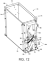
- the bin 70 shown in FIG. 12 can be used with a system for shifting objects, e.g., the system 10 shown in FIG. 2 , or another system.
- the bin 70 can also be used in a logistics network operation.
- the bin 70 can be used to transfer or route items such as parcels or packages (e.g., delivery boxes, bags, totes, or other transport receptacles) to their designated destinations, e.g., associated with a downstream location, and/or associated with a final, ultimate, and/or terminal destination of the parcels or packages.
- the bin 70 can be configured, operated, and/or used to hold objects that have been re-oriented to be supported on a side of smallest and/or shortest dimension. This can allow objects, e.g., parcels and packages, to be shifted in the bin 70 while occupying a smallest possible ground-area footprint. This can allow a greater density and thus volume of objects to be processed in a given area, among other benefits.
- the bin 70 includes a base 72.
- the bin 70 also includes at least one sidewall 74.
- the at least one sidewall 74 extends from the base 72 to an opening 76.
- the opening 76 is located generally at a top end of the bin 70.
- the bin 70 also includes a releasing mechanism 78.
- the releasing mechanism 78 is located generally at a bottom end of the bin 70 adjacent to the base 72.
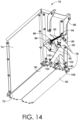
- the releasing mechanism 78 is capable of supporting objects in the bin 70 in a closed configuration, e.g., as shown generally in FIGS. 12-14 .
- the releasing-mechanism 78 is also capable of releasing or dropping objects from the bin 70 in an open configuration, e.g., as shown generally in FIG. 15 .
- the releasing mechanism 78 includes a pair of doors 80, 82.
- the doors 80, 82 are adjustable between the closed configuration, e.g., as shown generally in FIGS. 12-14 , and the open configuration, e.g., as shown generally in FIG. 15 .
- the doors 80, 82 can be slidably mounted adjacent to the base 72, e.g., being mounted on tracks along which the doors 80, 82 can slide/translate.
- the doors 80, 82 can be pivotally mounted adjacent to the base 72, e.g., being mounted on hinges that allow the doors 80, 82 to pivot, rotate, or otherwise rotationally displace (e.g., as depicted in FIG. 15 ).
- the doors 80, 82 can be slidably and pivotally mounted adjacent to the base 72 of the bin 70, e.g., so that motion of the doors 80, 82 includes a combination of sliding and pivoting.
- FIGS. 12-15 depict an embodiment with a pair of doors 80, 82.
- a releasing mechanism may include a different number of similar elements.
- a releasing mechanism can include a single sliding and/or pivoting door, or can include more than two sliding and/or pivoting doors.
- a releasing mechanism can include another configuration, e.g., a roller door, a sliding panel, a plurality of shutters, or other components that are pivoted, slid, or otherwise translated to allow objects to pass through.
- the releasing mechanism 78 can be operated manually, mechanically, electrically, and/or pneumatically, and/or in automated and/or semi-automated fashion in different embodiments contemplated herein.
- the releasing mechanism 78 can be operated using one or more actuators, e.g., that are attached to the bin 70, or that are attached to a system, e.g., such as the system 10 shown in FIG. 2 , such that the actuators and associated components interact with the releasing mechanism 78 at suitable points in time.
- the actuators in either configuration can be operated to open and close the doors 80, 82, e.g., through extending, retracting, pivoting, and/or otherwise adjusting structures that interact with the releasing mechanism 78.
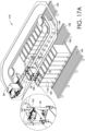
- the aforementioned actuators can be connected to a control system, e.g., associated with a shifting system, e.g., the system 10 shown in FIG. 2 , that directs operation of the actuators and associated structures. Example operations of such actuators are further discussed in connection with FIGS. 17A and 17B .
- the bin 70 also includes a support-structure 86 and a support-structure 88.
- the support structures 86, 88 are located generally on opposite sides of the bin 70, e.g., being attached to the sidewall(s) 74 thereof.
- the support structures 86, 88 can be used to support the bin 70 during different operations, e.g., loading, shifting (e.g., along a track), and/or during a process of releasing objects from the bin 70.
- the general lateral positioning of the support structures 86, 88 allows the bin 70 to be supported while limiting interference with operation of the releasing mechanism 78.
- the location of the support-structures 86, 88 can allow the doors 80, 82 to open and close substantially without interference.
- a single support structure can be used to support the bin 70, or a plurality of support structures, e.g., 2, 3, 4, 5, 6, or more support structures, can be used to support the bin 70.
- the support-structures 86, 88 may be fixed structures, or may be adjustable/operable, e.g., slidable, pivotable, rollable, and/or may be securable or lockable, e.g., to facilitate attachment and release of the bins 70 under different circumstances, e.g., loading and unloading of the bins 70, or other circumstances. In the embodiment depicted in FIGS.
- the support-structure 86 is generally a rigid, fixed structure
- the support-structure 88 is generally a non-rigid or non-fixed structure, e.g., due to including a wheel 75.
- the wheel 75 (shown in FIG. 16 ) can be used to support the bin 70 by rolling along a surface, e.g., associated with a track, e.g., such as the track(s) 20 of the system 10 shown in FIG. 2 .
- the releasing mechanism 78 includes a pivot-mechanism 85.
- the pivot-mechanism 85 includes a cam plate 90 that is pivotally coupled to a linkage 84 that is pivotally coupled to the doors 80, 82.
- the cam plate 90 is mounted on a pivot-connection 92 attached to the sidewall(s) 74 of the bin 70. This configuration allows the cam plate 90 to rotate on the pivot-connection 92.
- the pivot-mechanism 85 also includes a spring 95.
- the spring 95 extends between a spring-connection 94 located on the cam plate 90 and a spring-connection 96 located on a bracket 98 that is attached to the sidewall(s) 74 of the bin 70.
- the linkage 84 shown in FIGS. 12 , 14 , and 15 includes an assembly of components that can shift in coordination to either open the doors 80, 82, or close the doors 80, 82, depending on the direction of rotation of the cam plate 90.
- one end of the linkage 84 is pivotally coupled to the cam plate 90, and the other end of the linkage 84 is pivotally coupled to the doors 80, 82.
- the rotational position of the cam plate 90 corresponds to a position of the doors 80, 82, e.g., open or closed.
- the position of the cam plate 90 shown in FIG. 15 corresponds to the doors 80, 82 being generally open.
- the position of the cam plate 90 in FIG. 12 corresponds to the doors 80, 82 being generally closed.
- the linkage 84 includes an arm 100.
- the arm 100 is coupled to a pivot-connection 104 on the door 80.
- the arm 100 is also coupled to a pivot-connection 106 on the cam plate 90, as shown in FIG. 12 .
- the pivot-connection 106 is partially obscured in FIG. 12 , but it is generally located between the cam plate 90 and the sidewall(s) 74 of the bin 70.
- the linkage 84 also includes an arm 102.
- the arm 102 is pivotally coupled to a pivot-connection 108 on the door 82.
- the arm 102 is also coupled to a pivot-connection 105 on the cam plate 90.
- the pivot-connection 105 is partially obscured in FIG.
- the pivot-connections 105, 106 may be connected to the cam plate 90 at spaced-apart locations, or may be connected to the cam plate 90 at a common location. In either configuration, when the releasing mechanism 78 is operated, the cam plate 90 is rotated, shifting the linkage 84 such that the arms 100, 102 apply a force to the doors 80, 82 that opens them, e.g., as shown in FIG. 15 .
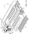
- FIGS. 16 , 17A-17B , 18A-18B , and 19A-19B a system 110 for shifting, re-orienting, and loading objects, e.g., parcels and packages, is shown, in accordance with an embodiment of the present disclosure.
- the system 110 may form part of a larger overall system, e.g., the system 10 shown in FIG. 2 , among others.
- the system 110 is depicted with some components omitted for clarity and explanation purposes.
- 16-19B show the system 10 performing a sequence of operations, e.g., shifting, re-orienting, and depositing objects in storage receptacles, e.g., in furtherance of routing the objects to a downstream location, as described further below.
- a sequence of operations e.g., shifting, re-orienting, and depositing objects in storage receptacles, e.g., in furtherance of routing the objects to a downstream location, as described further below.
- the system 110 includes the object-orienting mechanism 26, e.g., as described in connection with FIGS. 3-11 .
- the system 110 also includes the object-supply mechanism 14 (with some elements omitted for clarity), e.g., as described in connection with FIG. 2 .
- the system 110 includes a plurality of the bins 70, e.g., as described in connection with FIGS. 12-15 .
- the bins 70 are mounted on the track(s) 20. This allows the bins 70 to shift around the system 110 on the track(s) 20.
- the track(s) 20 include at least one belt 112 extended over a plurality of rollers 113 (which may be driven by rotational actuators).
- the track(s) 20 also includes a plurality of support structures 114 (a limited selection of which is shown in FIGS. 16 , 17A-17B , and 18A-18B for clarity purposes).
- the support structures 114 are attached to the belt 112 in spaced-apart relation, or rather, in a spaced-apart sequence.
- the support structures 86 on one side of the bins 70 are coupled to the support structures 114 on the belt 112.
- the support structures 88 on the other sides of the bins 70 are supported on the track(s) 20.
- the wheels 75 of the support structures 88 are able to roll along the track(s) 20, thereby supporting the other side of the bins 70.
- This support configuration allows the bins 70 to remain in an upright orientation, e.g., during loading, shifting, and releasing of objects.
- the system 110 includes a plurality of containers 116.
- the containers 116 each include a base 118, at least one sidewall 120, and an opening 122.
- the opening 122 is alignable with the releasing mechanism 78 at the bottom of each bin 70.
- the releasing mechanism 78 can then be shifted into an open configuration that allows objects in the bin 70 to drop into the container 116.
- the containers 116 once loaded, can then be shifted from a support structure 126 onto a track 124 that is adjacent to the support structure 126.
- the track 124 can be a passive track, an active track, or a combination thereof.
- the track 124 can include a conveyor mechanism, or can include a plurality of rollers, e.g., that are powered with rotational actuators, or can include other mechanisms that facilitate shifting of loaded containers 116, e.g., as shown in FIG. 18A .
- the containers 116 may be omitted, and objects may simply be dropped onto a track, conveyor, or similar mechanism, e.g., for downstream processing.
- the generally movable container 116 can be replaced with a static container that includes a releasing mechanism (e.g., one that can shift between a closed, object-supporting configuration and an open, object-releasing configuration) at its base.
- the releasing mechanism can include at least one door that is manually opened and closed, or that is opened and closed through operation of an associated actuator.
- the static container instead of being displaced and then shifted downstream as discussed in connection with FIGS. 16-19B , can remain substantially in place until a set number of objects have been deposited in the static container. These deposited objects can then be released from the static container through operation of the associated releasing mechanism. The released objects can then fall onto another shifting mechanism (e.g., a belt-driven conveyor) as a group that is then shifted to a downstream location for further processing (e.g., sorting, bagging, packaging, labeling, scanning, and/or further routing, among other things).
- This alternative configuration can also be implemented throughout the system 10 shown in FIG. 2 .
- an object 128 is positioned on the object-orienting mechanism 26.
- the object 128 may be a parcel or package that is being routed to a particular destination, e.g., one downstream in the logistics network, or one associated with a final, ultimate delivery destination, e.g., such as a recipient location.
- the object 128 may be a substantially structured object, e.g., a box, bin, container, or other storage element that maintains a substantially fixed geometry.
- the object 128 can be an unstructured or partially unstructured object, e.g., a bag, soft-sided tote, or other storage receptacle that does not maintain a substantially fixed geometry, i.e., it can at least partially change shape.
- the system 110 and components thereof can be configured to handle either form of such objects, or both, during a shifting operation.
- the object 128, having been introduced into the object-orienting mechanism 26 by the object-supply mechanism 14, has been re-oriented, e.g., into an upright orientation, with the shortest and/or smallest dimensional side oriented downward.
- the bin 70 can be size to hold the object 128 while resting on its shortest and/or smallest dimensional side.
- This shortest and/or smallest dimensional side can correspond with a cross-sectional area of the bin 70, so that objects of a range of different dimensions can fit into the bin 70, as long as the shortest and/or smallest dimensional side of the objects fits into the bin 70.
- FIG. 16 the object-orienting mechanism 16 is adjusted so that the re-oriented object 128 is released through the chute 64 into the bin 70 that is located underneath the object-orienting mechanism 16. During this transfer, the releasing mechanism 78 on the bin 70 is in the closed configuration so that it supports the deposited object 128.
- the containers 116 like the object 128, can be associated with particular destinations, e.g., downstream locations in a logistics network, or routes in a logistics network. As shown in FIGS.
- the bin 70 is eventually shifted into position above a container 116 that is associated with a routing of the object 128 stored in the bin 70.
- This can be determined by a control system, e.g., the control system 15 described in connection with FIG. 2 , that operates in connection with the system 110.
- the control system can monitor the locations of the object 128, the bins 70, and the containers 116 and coordinate transfer based on routing information stored in memory.
- the locations and identities of the objects, bins, and containers can be tracked using different techniques, e.g., through scanning of tracking indicia, e.g., such as machine-readable indicia, through image-recognition, through radio-frequency identification (“RFID”), or through other forms of tracking.
- RFID radio-frequency identification
- FIGS. 17A and 17B a process of actuating the releasing mechanisms 78 on the bins 70 in order to release objects, e.g., the object 128, into the containers 116 positioned below is shown, in accordance with an embodiment of the present disclosure.
- the bins 70 are being shifted along the track(s) 20.
- the system 110 can operate the appropriate linear actuator 140, extending its structure 142 into contact with the cam plate 90 on the releasing mechanism 78, e.g., as shown in FIG. 17A .
- the system 110 then operates the linear actuator 140 to retract the structure 142, so that the bins 70 can then pass by that location on the track(s) 20 without the releasing mechanisms 78 being operated, e.g., as shown in FIG. 17B .
- FIG. 18A the object 128 has been deposited into the container 130, and the container 130 is being shifted onto the track 124, for further routing of the object 128 and container 130.
- This shifting of the container 130 can be performed by a mechanism that is operable to translate the containers 116 laterally outward from the track(s) 20, and onto the track 124.
- a pusher-mechanism 136 e.g., one that is electrically, mechanically, pneumatically, and/or hydraulically operated
- FIG. 18B a pusher-mechanism 136 (e.g., one that is electrically, mechanically, pneumatically, and/or hydraulically operated) is shifted into contact with the container 130 such that it pushes the container 130 out onto the track 124, as shown in FIG. 18B .
- the pusher-mechanism 136 is shiftable along a length of the track(s) 20, so that its shiftable components can be used to displace different containers 116 along the length of the track(s) 20. In other embodiments, multiple pusher-mechanisms can be positioned along the length of the track(s) 20 for use in displacing different containers 116.
- the operation of the pusher-mechanism 136 can be directed by a control system associated with the system 110.
- FIG. 18B shows the container 130 displaced by the pusher-mechanism 136 and being transferred along the track 124.
- the track 124 includes rollers 132.
- the rollers 132 can be passive or powered.
- the rollers 132 can be rotated by actuators, e.g., to facilitate transferring of the container 130 down the track 124 toward a downstream location, e.g., for further processing.
- the container 130 with the object 128 may travel to a location where another object is loaded, or where the object 128 is removed, transferred, and further processed using other components associated with the system 110, e.g., a container-flipping mechanism 134 as shown in FIGS. 19A and 19B .
- FIGS. 19A and 19B the system 110 is again shown, but with a container-flipping mechanism 134 located at the end of the track 124, in accordance with an embodiment of the present disclosure.
- the container-flipping mechanism 134 can be used in coordination with the system 110, e.g., to engage, lift, and flip containers 116 to displace the objects loaded therein from the bins 70 for further shifting, sorting, and/or routing, among other things.
- the container-flipping mechanism 134 may be located at a downstream location where the container 130 with the object 128 is subsequently transferred as shown in FIGS. 19A and 19B .
- the container-flipping mechanism 134 includes a frame 138 that is shaped to receive, and support, the container 130 as shown in FIGS. 19A and 19B .
- the container-flipping mechanism 134 includes an actuator assembly 144 that allows the supported container 130 to be lifted, rotated, and oriented such that the object 128 can be ejected, e.g., down a chute 146 adjacent to the container-flipping mechanism 134.
- the chute 146 may allow objects to be deposited at a subsequent location, e.g., into another container 148 as shown in FIGS. 19A and 19B , or onto another mechanism, e.g., such as a conveyor.
- FIG. 20 another system 150 for transferring objects is shown, in accordance with an embodiment of the present disclosure.
- the system 150 is similar to the system 110.
- the system 150 includes the track 20, the bins 70, and the containers 116.
- the system 150 like the system 110 can be used to shift objects, e.g., for routing to a downstream location.
- the system 150 additionally includes object-guides 152.
- the example object-guides 152 shown in FIG. 20 each include a substantially rigid portion 154 and a substantially non-rigid portion 155.
- the rigid portion 154 can be formed of metal, metal alloy, and/or polymers of sufficient rigidity to substantially maintain a constant geometry.
- the non-rigid portion 155 can be formed of similar or different materials that have a higher degree of elasticity or flexibility (e.g., as determined using ASTM-E8/E8M or ASTM D790 or ASTM D6272) than the rigid portion 154.
- the rigid portion 154 may be formed of sheet metal or sheet metal alloy, and the non-rigid portion 155 may be formed of more flexible metal, composite, or polymer bristles, among other possibilities.
- the object-guides 152 have been demonstrated through testing to increase the consistency of object deposit within the containers 116, among other benefits.
- FIG. 21 depicts the object-orienting mechanism 26 generally of FIG. 3 with additional object-guiding features included, in accordance with an embodiment of the present disclosure.
- the object-orienting mechanism 26 is positioned over one of the bins 70.
- Installed generally between the object-orienting mechanism 26 and the bin 70 is another object-guide 156.
- the object-guide 156 includes a frame 158 and a plurality of extensions 160 that extend from the frame 158 towards the object-orienting mechanism 26 generally so that the plurality of extensions 160 are aligned with a trajectory of an object that passes from the object-orienting mechanism 26 to the bin 70. This configuration has been demonstrated to increase the consistency of object deposit into the bin 70, among other benefits.
- the object-guide 156 can be formed of substantially rigid materials as described in connection with FIG. 21 .
- FIGS. 22A-22C depict additional configurations of a bin used for transporting objects, e.g., as described in connection with FIGS. 12-15 , in accordance with an embodiment of the present disclosure.
- FIGS. 22A-22C again depict the pair of doors 80, 82 attached to the releasing mechanism 78 as described in connection with FIGS. 12-15 .
- the edges of the doors 80, 82 that substantially adjoin and abut each other in the closed configuration (generally shown in FIGS. 22A-22C ) have different geometries.
- edges 162 of the doors 80, 82 form a non-linear and substantially interlocking pattern, and in FIG.
- edges 164 of the doors 80, 82 form a non-linear and substantially zig-zag, interlocking pattern
- edges 166 of the doors 80, 82 form a non-linear and substantially wave-like, interlocking pattern.
- the method 2300 includes shifting an object, e.g., a parcel or package being routed to a destination, e.g., in a logistics network, using an object-shifting mechanism, e.g., the object-supply mechanism 14 shown in FIG. 2 .
- the method 2300 includes engaging the object with an object-orienting mechanism, e.g., the object-orienting mechanism 26 shown in FIG. 3 .
- the object-orienting mechanism may include a first-pivoting extension, e.g., the pivoting-extension 46 shown in FIG. 3 , and a second pivoting-extension, e.g. the pivoting-extension 48 shown in FIG. 3 , wherein the first pivoting-extension and the second pivoting-extension can rotate independently about a common pivot-assembly, e.g., the pivot-assembly 30 shown in FIG. 3 .
- the method 2300 includes pivoting the object using the object-orientating mechanism so that the object has its smallest dimensional side oriented in a substantially downward direction, e.g., at least partially towards a ground surface, e.g., at least partially aligning with a direction of gravity, and substantially towards a chute, e.g., the chute 64 shown in FIG. 3 .
- the method 2300 includes adjusting the orientation of the first pivoting-extension and the second pivoting-extension relative to each other to release the object down the chute, e.g., pivoting at least one of the first-pivoting extension and the second pivoting extension to align at least partially with the chute, allowing the object to drop using gravity, e.g., into a bin for further shifting, organizing, and/or routing, as described herein.
- a system for shifting objects comprising an object-supply mechanism; an object-orienting mechanism positioned such that the object-supply mechanism can transfer objects onto the object-orienting mechanism; a track extending under the object-orienting mechanism; a plurality of bins shiftable along the track; and a shifting mechanism operable to shift the plurality of bins along the track such that each bin passes under the object-orienting mechanism, wherein each bin comprises a base, at least one sidewall extending from the base to an opening that is alignable with the object-orienting mechanism, and a releasing mechanism at the base that is adjustable between a closed configuration and an open configuration.
- Clause 3 The system of clause 1 or 2, wherein the object-orienting mechanism comprises a plurality of pivoting-extensions coupled to a pivot-assembly, and wherein the plurality of pivoting-extensions are shiftable to different positions relative to each other.
- each support structure engages a corresponding bin on at least one side thereof, and wherein each bin includes a wheel that is supportable on the track.
- the shifting mechanism comprises at least one rotational actuator that is operable to translate the at least one belt along the track, wherein the track is a substantially continuous track, and wherein the track transitions to different vertical heights.
- Clause 7 The system of any of clauses 1-6, wherein the releasing mechanism comprises a pair of doors, a cam plate pivotally coupled to the bin; a linkage pivotally connected to the cam plate and pivotally connected to the pair of doors, the linkage adjustable between a first configuration, in which the pair of doors are substantially closed, and a second configuration, in which the pair of doors are substantially open.
- Clause 8 The system of any of clauses 1-7, further comprising at least one linear actuator, wherein each linear actuator is adjustable between a retracted position and an extended position, wherein, in the extended position, the linear actuator operates the releasing mechanism on each bin that is shifted into contact with the linear actuator using the shifting mechanism.
- Clause 9 The system of any of clauses 1-8, further comprising a separate track that extends under at least part of the track; and a plurality of containers supportable on the separate track, wherein each container comprises a base, and at least one sidewall extending from the base to an opening that is alignable with the base of a bin positioned on the track, such that when the releasing mechanism of the bin positioned on the track is opened, objects in the bin are released into the container.
- Clause 10 The system of any of clauses 1-9, further comprising a container-flipping mechanism; and a chute comprising an opening, wherein the container-flipping mechanism is adapted to engage a container on the separate track and flip it so that the opening of the container is at least partially aligned with the opening of the chute.
- An object-orienting mechanism comprising a pivot-assembly; a first pivoting-extension coupled to the pivot-assembly and to a first rotational actuator; and a second pivoting-extension coupled to the pivot-assembly and to a second rotational actuator, wherein the first pivoting-extension and the second pivoting-extension are independently rotatable about the pivot-assembly.
- Clause 13 The object-orienting mechanism of clause 11 or 12, wherein the first pivoting-extension and the second pivoting-extension are rotatable into substantially linear alignment along a common-facing direction, and wherein the first pivoting-extension and the second pivoting-extension are rotatable into substantially linear alignment along opposite-facing directions.
- Clause 14 The object-orienting mechanism of any of clauses 11-13, wherein the first pivoting-extension is at least twice a length of the second pivoting-extension.
- Clause 15 The object-orienting mechanism of any of clauses 11-14, wherein the first pivoting-extension comprises a first plurality of spaced-apart fingers, and wherein the second pivoting-extension comprises a second plurality of spaced-apart fingers, and wherein the first plurality of spaced-apart fingers and the second plurality of spaced-apart fingers are rotatable into a common plane to form an alternating sequence.
- Clause 16 The object-orienting mechanism of any of clauses 11-15, further comprising a plurality of transfer mechanisms positioned adjacent to the first pivoting-extension, the plurality of transfer mechanisms spaced-apart and arranged in a substantially parallel configuration, wherein the first pivoting-extension is rotatable into substantially linear alignment with the plurality of transfer mechanisms, such that the first plurality of fingers and the plurality of transfer mechanisms are arranged in an alternating sequence.
- each transfer mechanism comprises a belt positioned over a plurality of rollers.
- Clause 18 The object-orienting mechanism of any of clauses 11-17, further comprising a chute positioned adjacent to the pivot-assembly, wherein the first pivoting-extension is configured to lift an object positioned on the plurality of transfer mechanisms, and rotate the object toward the chute while supporting the object with the second pivoting-extension that is oriented approximately perpendicular to the first pivoting-extension, and then release the object into the chute by shifting the first pivoting-extension and the second pivoting-extension into an opposite-extension orientation.
- a bin for transporting objects comprising a base; at least one sidewall extending from the base to an opening; and a releasing mechanism attached to the base, the releasing mechanism comprising a pair of doors, a cam plate pivotally coupled to the at least one sidewall, and a linkage pivotally connected to the cam plate and pivotally connected to the pair of doors, the linkage adjustable between a first configuration, in which the pair of doors are substantially closed, and a second configuration, in which the pair of doors are substantially open.
- Clause 20 The bin of clause 19, wherein the bin further comprises a first support-structure extending from a first side of the bin; and a second support-structure extending from a second side of the bin.
- Clause 21 The bin of clause 19 or 20, wherein the linkage comprises a first arm comprising a first end and a second end, the first end of the first arm pivotally coupled to the cam plate, and the second end of the first arm pivotally coupled to a first one of the pair of doors, and a second arm comprising a first end and a second end, the first end of the second arm pivotally coupled to the cam plate, and the second end of the second arm pivotally coupled to a second one of the pair of doors.
- a method of re-orienting objects during routing comprising shifting an object using an object-shifting mechanism; engaging the object using an object-orienting mechanism comprising a first pivoting-extension, and a second pivoting-extension, wherein the first pivoting-extension and the second pivoting-extension rotate independently about a pivot-assembly; pivoting the object using the object-orienting mechanism so that the object has its smallest dimensional side oriented in a substantially downward direction and substantially towards a chute; and adjusting an orientation of the first pivoting-extension and the second pivoting-extension relative to each other to release the object down the chute.
- this disclosure may include the language, for example, "at least one of [element A] and [element B].” This language may refer to one or more of the elements. For example, “at least one of A and B” may refer to “A,” “B,” or “A and B.” In other words, “at least one of A and B” may refer to “at least one of A and at least one of B,” or “at least either of A or B.” In some embodiments, this disclosure may include the language, for example, “[element A], [element B], and/or [element C].” This language may refer to either of the elements or any combination thereof. In other words, “A, B, and/or C” may refer to “A,” “B,” “C,” “A and B,” “A and C,” “B and C,” or “A, B, and C.”
Landscapes
- Engineering & Computer Science (AREA)
- Mechanical Engineering (AREA)
- Warehouses Or Storage Devices (AREA)
- Specific Conveyance Elements (AREA)
- Discharge Of Articles From Conveyors (AREA)
Abstract
Description
- The field relates to automated handling of objects.
- The shifting of objects, e.g., parcels and packages, presents unique challenges. For example, objects of different sizes and shapes often require different handling processes or different handling equipment, and in addition, processing a large number of objects can require significant space. In addition, shifting a large number of objects can sometimes require a significant amount of manual handling. This can increase the cost, space, and/or time required to process the objects, among other challenges.
- This summary is intended to introduce a selection of concepts in a simplified form that are further described below in the detailed description section of this disclosure. This summary is not intended to identify key or essential features of the claimed subject matter, nor is it intended to be used as an aid in isolation to determine the scope of the claimed subject matter.
- In brief, and at a high level, this disclosure describes, among other things, systems, methods, apparatuses, and technologies for shifting, orienting, organizing, and/or routing objects including parcels and packages, among other things. These embodiments may be implemented in a logistics network operation, among other instances. In one aspect, a system is provided that can shift and/or re-orient objects, e.g., based on their shape and/or dimensions, and then release the objects into transport receptacles for further shifting, organizing, and/or routing. In another aspect, an object-orienting mechanism is provided. The object-orienting mechanism can include a pivot-assembly, a plurality of pivoting-extensions, e.g., that can be independently rotated into different positions, and a plurality of actuators, e.g., that can shift the pivoting-extensions, e.g., at the direction of a control system. In another aspect, a bin for transporting objects is provided. The bin can include a base, at least one sidewall extending to an opening, and a releasing mechanism that is operable to support or release objects deposited into the bin. In another aspect, a container that can support objects is provided, and a container-flipping mechanism that can be used to displace objects from the container is provided. In another aspect, a process of re-orienting, re-positioning, and/or depositing objects is provided. In one instance, objects can be re-oriented onto a side of shortest and/or smallest dimension, e.g., to allow for processing using a smallest available footprint, among other benefits. In summary, the embodiments described herein can support faster, more effective, and more space-efficient shifting and processing of objects, e.g., in a logistics network operation, among other benefits.
- The embodiments described herein that can be used for shifting, orienting, organizing, and/or routing objects including parcels and packages are described in detail in connection with the attached drawing figures, which are intended to illustrate non-limiting examples of the disclosed subject matter, wherein:
-
FIG. 1 depicts a block diagram of a computer system suitable for supporting and performing different functions described herein; -
FIG. 2 depicts a system for shifting objects, in accordance with an embodiment of the present disclosure; -
FIG. 3 depicts an object-orienting mechanism, in accordance with an embodiment of the present disclosure; -
FIGS. 4A-4B depict the object-orienting mechanism ofFIG. 3 from different perspectives, and with components omitted for clarity, in accordance with an embodiment of the present disclosure; -
FIGS. 5-11 depict the object-orienting mechanism ofFIG. 3 in a sequence of different operational configurations, in accordance with embodiments of the present disclosure; -
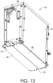
FIGS. 12-15 depict different perspectives of a bin used for supporting and releasing objects, in accordance with an embodiment of the present disclosure; -
FIG. 16 depicts part of a system used for transferring objects for subsequent shifting, processing, and/or routing, in accordance with an embodiment of the present disclosure; -
FIGS. 17A-17B depict the system ofFIG. 16 showing the operation of a releasing mechanism on a bin, in accordance with an embodiment of the present disclosure; -
FIGS. 18A-18B depict the system ofFIG. 16 with a pusher-mechanism being used to shift a container onto a track, in accordance with an embodiment of the present disclosure; -
FIGS. 19A-19B depict the system ofFIG. 16 along with a container-flipping mechanism that is used to transfer objects, in accordance with an embodiment of the present disclosure; and -
FIG. 20 depicts a system for transferring objects that includes additional object-guiding features, in accordance with an embodiment of the present disclosure; -
FIG. 21 depicts the object-orienting mechanism generally ofFIG. 3 with additional object-guiding features included, in accordance with an embodiment of the present disclosure; -
FIGS. 22A-22C depict additional configurations of a bin used for transporting objects, in accordance with an embodiment of the present disclosure; -
FIG. 23 is a block diagram of a method for shifting objects, in accordance with an embodiment of the present disclosure. - This detailed description is provided in order to meet statutory requirements. However, this description is not intended to limit the scope of the invention. Rather, the claimed subject matter may be embodied in other ways, to include different steps, different combinations of steps, different features, and/or different combinations of features, similar to those described in this disclosure, and in conjunction with other present or future technologies or techniques. In addition, while the terms "step" or "block" may be used herein to identify different elements of methods employed, the terms should not be interpreted as implying any particular order among or between the described elements except when the order is explicitly stated.
- In general, and at a high level, this disclosure describes, among other things, embodiments that support and enable the shifting, re-orienting, organizing, and/or routing of objects, e.g., parcels and packages, e.g., in a logistics network operation, among other things. In some aspects described herein, objects can be handled, processed, and/or transferred more efficiently through re-orienting the objects onto a side of shortest or smallest dimension. This can be used to reduce or limit the footprint of the objects, e.g., during storage and transfer, which can allow a greater number of objects to be processed and/or allow objects to be processed with greater efficiency. Different embodiments that support such efficient processing, including object-orienting mechanisms, object-shifting mechanisms, storage bins, containers, and the like, are described in detail below in connection with accompanying
FIGS. 1-23 . - The subject matter of this disclosure may be provided as, at least in part, a method, a system, and/or a computer program product, among other things. Accordingly, certain aspects described herein may be hardware, software, or may be a combination of software and hardware. A computer program that includes computer-useable instructions embodied on one or more computer-readable media may also be used. The subject matter herein may further be implemented as hard-coded into the mechanical design of computing components and/or may be built into a system or components thereof used for shifting, re-orienting, organizing, and/or routing objects such as parcels and packages, e.g., such as boxes, containers, bags, pouches, carriers, totes, and the like.
- Computer-readable media may include volatile media, non-volatile media, removable media, and non-removable media, and may also include media readable by a database, a switch, and/or various other network devices. Network switches, routers, and related components are conventional in nature, as are methods of communicating with the same, and thus, further elaboration is not provided in this disclosure. By way of example, and not limitation, computer-readable media may include computer storage media and/or non-transitory communications media.
- Computer storage media, or machine-readable media, may include media implemented in any method or technology for storing information. Examples of stored information include computer-useable instructions, data structures, program modules, and/or other data representations. Computer storage media may include, but is not limited to, RAM, ROM, EEPROM, flash memory or other memory technology, CD-ROM, digital versatile discs (DVD), holographic media or other optical disc storage, magnetic cassettes, magnetic tape, magnetic disk storage, and other storage devices. These memory components may store data momentarily, temporarily, and/or permanently, and are not limited to the examples provided herein.
- Referring now to
FIG. 1 , a block diagram of anexample computing device 1 suitable for supporting and performing functions described herein is provided, in accordance with an embodiment of the present disclosure. It should be noted that although some components depicted inFIG. 1 are shown in the singular, they may be plural, and the components may be connected in a different, including distributed, configuration. For example,computing device 1 might include multiple processors and/or multiple radios. Thecomputing device 1 shown inFIG. 1 includes abus 9 that may directly or indirectly connect different components together, e.g., such asmemory 2, processor(s) 3, presentation component(s) 4 (if applicable), radio(s) 5, input/output (I/O) port(s) 6, input/output (I/O) component(s) 7, and/orpower supply 8. -
Memory 2 may take the form of the memory components described herein. Thus, further elaboration will not be provided here, butmemory 2 may include any type of tangible medium that is capable of storing information, such as a database. A database may include any collection of records, data, and/or other information. In one embodiment,memory 2 may include a set of computer-executable instructions that, when executed, facilitate various functions or steps associated with the subject matter described herein. These instructions will be referred to as "instructions" or an "application" for short. Theprocessor 3 may actually be multiple processors that may receive instructions and process them accordingly. Thepresentation component 4 may include a display, a speaker, a screen, a portable digital device, and/or other components that can present information through visual, auditory, and/or other tactile cues (e.g., a display, a screen, a lamp, a light-emitting diode (LED), a graphical user interface (GUI), and/or a lighted keyboard). - The
radio 5 may facilitate communication with a network, and may additionally or alternatively facilitate other types of wireless communications, such as Wi-Fi, WiMAX, LTE, Bluetooth, and/or VoIP communications, among other possible communication protocols. In various aspects, theradio 5 may be configured to support multiple technologies, and/or multiple radios may be configured and utilized to support multiple technologies in the embodiments contemplated herein. - The input/output (I/O)
ports 6 may take a variety of forms. Example I/O ports may include a Universal Serial Bus ("USB") jack, a stereo jack, an infrared port, and/or other proprietary communications ports. The input/output (I/O) components 7 may include one or more keyboards, microphones, speakers, touchscreens, and/or any other item useable to directly or indirectly input data into thecomputing device 1. Thepower supply 8 may comprise batteries, generators, fuel cells, an electrical supply source and/or any other component that may act as a power source to supply power tocomputing device 1 and to any other components described herein. - Looking now at
FIG. 2 , asystem 10 for shifting objects, e.g., theobjects 12, is shown, in accordance with an embodiment of the present disclosure. Thesystem 10 is represented inFIG. 2 as a collection of structures, mechanisms, and technologies that operate in coordination to shift, re-orient, store, organize, and/or route theobjects 12 to different locations. In different instances, theobjects 12 can be boxes, containers, bags, pouches, carriers, totes, and the like. Thesystem 10 can be used in a logistics network operation, among other possible uses. - The
system 10 includes object-supply mechanisms 14. In one embodiment, each object-supply mechanism 14 is a conveyor, or a series of conveyors, e.g., those that include one or more belts, rollers, actuators, and/or other components. The object-supply mechanisms 14 can be used to initially transfer theobjects 12 through thesystem 10, e.g., transiting them towards object-orientingmechanisms 16. The object-orientingmechanisms 16 can be used to re-orient the objects 12 (if needed), e.g., into a desired orientation for loading intostorage bins 18. The selected orientation can be such that theobject 12 is resting or supported on its shortest or smallest dimensional side, among other possible orientations. Theobjects 12 can then be deposited into thebins 18, and then transferred around thesystem 10 along track(s) 20. - Looking still at
FIG. 2 , thestorage bins 18 are transferred through thesystem 10 along the track(s) 20 such that eachstorage bin 18 is eventually routed under at least one of the object-orientingmechanisms 16. This allows theobjects 12 that are supplied by the object-supply mechanisms 14 to be engaged, re-oriented, and then released/deposited by the object-orientingmechanisms 16 into thestorage bins 18 that are sequentially positioned under the object-orientingmechanisms 16. Next, thestorage bin 18 with theobject 12 can be shifted along the track(s) 20 until thestorage bin 18 is in position over aparticular container 23, e.g., one associated with a downstream location of theobject 12, and/or one associated with an ultimate destination of theobject 12. Thecontainers 23 can be supported and transferred along atrack 22, and subsequently manipulated by additional mechanisms, e.g., a container-flipping mechanism that can transfer theobjects 12 in thecontainers 23 to other parts of thesystem 10. The displacement of thecontainers 23 can be facilitated using different mechanisms, e.g., linear actuators, pushers, and the like. In different embodiments, thetrack 22 can be a passive track (e.g., having a series of passive rollers), a powered track (e.g., having a series of powered rollers or conveyors), or a combination thereof. Thetrack 22 shown inFIG. 2 includes a series ofrollers 24. The operation of different components of thesystem 10, e.g., such as the object-supply mechanisms 14, the object-orientingmechanisms 16, the track(s) 20, the track(s) 22, and other associated components, mechanisms, actuators, and technologies, may be directed by acontrol system 15, e.g., one that includes one or more computing devices, communication components, and/or supporting software applications. - Looking now at
FIG. 3 , an object-orientingmechanism 26 is shown, in accordance with an embodiment of the present disclosure. The object-orientingmechanism 26 includes an assembly of components that operate in coordination to shift and re-orient an object, e.g., a parcel, package, or other receptacle, into a different orientation. This re-orienting of objects can be performed in furtherance of routing the objects, e.g., towards a downstream and/or final location. In addition toFIG. 3 ,FIGS. 4A and 4B show the object-orientingmechanism 26 with some components omitted for clarity, simplicity, and explanation. - The object-orienting
mechanism 26 includes ahousing 28 and aframe 25 that supports thehousing 28. The object-orientingmechanism 26 also includes a pivot-assembly 30. The pivot-assembly 30 provides a common axis of rotation for multiple elements including pivoting-extensions mechanism 26 also includes a plurality ofactuators mechanism 26. In the example embodiment ofFIGS. 3-11 , theactuators actuators actuators assemblies assemblies assemblies actuators mechanism 26, e.g., such as the pivoting-extensions actuators control system 44 that can direct operation of theactuators control system 44 is depicted generically inFIG. 3 for explanation purposes, but can include computing components, communication components, software applications, and/or other technologies that support its operation. Thecontrol system 44 can be configured to operate theactuators - The object-orienting
mechanism 26 includes a pivoting-extension 46, a pivoting-extension 48, and ashifting mechanism 50. The pivoting-extension 46 is rotatably coupled to the pivot-assembly 30. The pivoting-extension 46 is also coupled to theactuator 32 through the belt-drivenassembly 38. Thus, operation of theactuator 32 translates the corresponding belt-drivenassembly 38 which rotates the pivoting-extension 46 to different positions on the pivot-assembly 30. The translation of the pivoting-extension 46 to different rotational positions is guided by asupport element 58 that shifts generally within a pair oftracks housing 28. The pivoting-extension 48 is also rotatably coupled to the pivot-assembly 30, and similarly is coupled to theactuator 34. Thus, operation of theactuator 34 translates the corresponding belt-drivenassembly 40, which rotates the pivoting-extension 48 into different rotational positions on the pivot-assembly 30. In different embodiments, the rotational force from theactuator 34 may be imparted directly to the pivoting-extension 48, or may be imparted indirectly to the pivoting-extension 48, e.g., through use of the belt-drivenassembly 40. The inclusion of theseparate actuators extensions extensions assembly 30. For example, in one instance, the pivoting-extension 46 may be at least twice the length (measured outward from the pivot-assembly 30) of the pivoting-extension 48. This differential in length can be based on the dimensions of objects being handled by the object-orientingmechanism 26, and has been demonstrated to facilitate the orienting of objects, e.g., parcels and packages, onto their shortest and/or smallest dimensional side, among other benefits. - The pivoting-
extension 46 includes a plurality of spaced-apart fingers 60 (only some of which are identified for clarity). The pivoting-extension 48 includes a plurality of spaced-apart fingers 62 (only some of which are identified for clarity). In addition, the pivoting-extensions assembly 30, i.e., about a common axis of rotation, such that thefingers 60 can shift between thefingers 62, and vice-versa. In other words, the axial-spacing and positioning of thefingers 60 across the pivot-assembly 30 and the axial-spacing and positioning of thefingers 62 across the pivot-assembly 30 is such that the pivoting-extensions FIG. 3 ) with thefingers fingers assembly 30 so that rotation of thefingers fingers extensions FIGS. 5-10 . - Looking at
FIGS. 3 ,4A, and 4B , the shiftingmechanism 50 is shown. The shiftingmechanism 50 includes a plurality of spaced-apart transfer mechanisms 52 (only some of which are identified for clarity) that are arranged in spaced-apart relation and in a substantially parallel configuration. Thetransfer mechanisms 52 can be operated to shift objects towards the pivoting-extensions extensions extensions transfer mechanisms 52 of theshifting mechanism 50, e.g., as shown inFIG. 3 . Thetransfer mechanisms 52 each include a belt-driven assembly, e.g., one that includes a belt/cable and a plurality of rollers, which can be rotated by theactuator 36 to translate objects supported on thetransfer mechanisms 52. - To shift objects onto the pivoting-
extension 46, thefingers 60 of the pivoting-extension 46 can be rotated about the pivot-assembly 30 substantially into planar alignment with thetransfer mechanisms 52, e.g., such that thefingers 60 are located generally between thetransfer mechanisms 52, generally aligned along the same plane, e.g., as shown inFIG. 3 . Theactuator 36 associated with the shiftingmechanism 52 can then be operated to shift an object supported on thetransfer mechanisms 52 onto thefingers 60 of the pivoting-extension 46. Then, with the object supported on the pivoting-extension 46, the pivoting-extension 46 can be rotated so that thefingers 60 lift the object into another position/orientation, e.g., in conjunction with the pivoting-extension 48. This shifting process is further described in connection withFIGS. 5-11 . - Looking at
FIG. 3 , it can be seen that the object-orientingmechanism 26 includes achute 64. Thechute 64 is defined at least partially by thehousing 28, and is designed to align with an opening in a storage receptacle positioned below the object-orientingmechanism 26. To provide an example, a process of shifting and re-orienting an object 68 (shown inFIG. 4A ) using the object-orientingmechanism 26 will be described. First, theobject 68 is transferred along the shiftingmechanism 50, onto the pivoting-extension 46, and then theobject 68 is lifted by the pivoting-extensions FIGS. 4A and 4B ), e.g., one in which the object is supported on its shortest and/or smallest dimensional side. Then, the pivoting-extensions object 68 is released to gravity, and subsequently slides, drops, or falls down thechute 64, e.g., as shown inFIG. 8 . This allows a re-oriented object to be shifted to a subsequent location (e.g., a storage receptacle, conveyor, or other location) for further processing while being supported on its shortest and/or smallest dimensional side. The re-orienting of an object onto its shortest and/or smallest dimensional side is demonstrated to provide numerous benefits. For example, positioning an object, e.g., such as theobject 68, on its shortest and/or smallest dimension side can allow for subsequent processing, e.g., shifting, organizing, and/or routing, of objects at a higher density (due to the smaller footprint occupied by the objects), and/or at a higher density particularly if a consistent selection of object sizes is used, e.g., as often is the case in a logistics network operation that transfers parcels, packages, and other transport receptacles. - Looking now at
FIG. 5 , the object-orientingmechanism 26 is again shown in a particular configuration, in accordance with an embodiment of the present disclosure. In particular,FIG. 5 shows the object-orientingmechanism 26 operated so that the pivoting-extension 46 is shifted, i.e., rotated, generally upward, and away from the shiftingmechanism 50. In addition, the pivoting-extension 48 has been rotated independently of the pivoting-extension 46, so that the pivoting-extension 46 andfingers 60 thereof and the pivoting-extension 48 andfingers 62 thereof are positioned approximately perpendicular, or orthogonal, to each other. This generally forms acradle 66 that supports an object being re-oriented, as discussed further in connection withFIGS. 6-11 . - Looking now at
FIGS. 6-11 , the object-orientingmechanism 26 is shown in a sequence of different configurations, i.e., being used to shift, re-orient, and then deposit an object, in accordance with an embodiment of the present disclosure.FIGS. 6-11 look into the object-orientingmechanism 26 generally from one side with thehousing 28 omitted for clarity, simplicity, and explanation. - Looking at
FIG. 6 , anobject 68 is shown being transferred along the shiftingmechanism 50 such that theobject 68 is shifted onto thefingers 60 of the pivoting-extension 46. In addition, the pivoting-extension 48 has been rotated on the pivot-assembly 30 so that the pivoting-extensions fingers cradle 66 that supports theobject 68. To achieve this configuration, the pivoting-extension 46 and/or the pivoting-extension 48 can be rotated independently using theirrespective actuators - Looking now at
FIG. 7 , the object-orientingmechanism 26 is again shown, but in a different configuration. InFIG. 7 , the pivoting-extension 46 and the pivoting-extension 48 have been rotated (e.g., independently) to form the approximately perpendicular configuration that provides thecradle 66 for theobject 68, and also, the pivoting-extension 46 and the pivoting-extension 48 have been rotated (e.g., in unison) to shift thecradle 66 and theobject 68 to a more upright rotational position. This upright position starts to support theobject 68 on its shortest and/or smallest dimensional side, as shown inFIG. 7 , and is closer to alignment with thechute 64 that extends through a bottom of the object-orientingmechanism 26. - Looking now at
FIG. 8 , the object-orientingmechanism 26 is again shown, but in a different configuration. In particular, inFIG. 8 , the pivoting-extension 48 is rotated (e.g., independently) such that it is extended generally in an opposite-facing direction compared to the pivoting-extension 46. In other words, the pivoting-extensions fingers object 68 along the pivoting-extensions chute 64. This configuration also generally eliminates thecradle 66, allowing theobject 68 to slide, fall, and ultimately drop through thechute 64 from the force of gravity. Theobject 68 can then land, e.g., in a storage receptacle, on its shortest and/or smallest dimensional side, e.g., to facilitate processing with maximum density. - Looking now at
FIG. 9 , the object-orientingmechanism 26 is again shown, but in a different configuration. In particular, theobject 68 is fully shifted off of the pivoting-extensions chute 64. In addition, inFIG. 9 , the pivoting-structure 48 has been rotated independently of the pivoting-structure 48 so that it transitions toward planar alignment with the pivoting-extension 46, e.g., in preparation for engaging and shifting another object, e.g., like theobject 68. - Looking now at
FIG. 10 , the object-orientingmechanism 26 is again shown, but in a different configuration. In particular, the pivoting-extension 48 has been rotated independently of the pivoting-extension 46 such that the pivoting-structure 46 and the pivoting-extension 48 again form thecradle 66. In particular, withFIG. 10 , the pivoting-extension 48 has been rotated through the pivoting-extension 46 (which is possible due to the offset positioning of thefingers 60, 62). In this sense, thefingers 62 of the pivoting-extension 48 have been rotated through thefingers 60 of the pivoting-extension 46, so that thefingers 60 and thefingers 62 are adjusted into a substantially perpendicular configuration, forming thecradle 66. In the alternative, thefingers 62 can be pivoted in the opposite rotational direction to similarly form thecradle 66 without passing through thefingers 60 of the pivoting-extension 46. - Looking now at
FIG. 11 , the object-orientingmechanism 26 is again shown, but in a different configuration. In particular, inFIG. 11 , the pivoting-extension 46 and the pivoting-extension 48 are rotated (e.g., in unison) in their perpendicular configuration, so that the pivoting-extension 46 and theshifting mechanism 50 are aligned, or rather, are substantially co-planar. In this configuration, thefingers 60 and thetransfer mechanisms 50 of the shifting mechanism are interposed, forming an alternating sequence across a common plane. - Looking now at
FIGS. 12-15 , abin 70 for storing, transporting, and/or releasing objects is shown, in accordance with an embodiment of the present disclosure. Thebin 70 shown inFIG. 12 can be used with a system for shifting objects, e.g., thesystem 10 shown inFIG. 2 , or another system. Thebin 70 can also be used in a logistics network operation. For example, thebin 70 can be used to transfer or route items such as parcels or packages (e.g., delivery boxes, bags, totes, or other transport receptacles) to their designated destinations, e.g., associated with a downstream location, and/or associated with a final, ultimate, and/or terminal destination of the parcels or packages. In addition, thebin 70 can be configured, operated, and/or used to hold objects that have been re-oriented to be supported on a side of smallest and/or shortest dimension. This can allow objects, e.g., parcels and packages, to be shifted in thebin 70 while occupying a smallest possible ground-area footprint. This can allow a greater density and thus volume of objects to be processed in a given area, among other benefits. - Looking still at
FIGS. 12-15 , thebin 70 includes abase 72. Thebin 70 also includes at least onesidewall 74. The at least onesidewall 74 extends from the base 72 to anopening 76. Theopening 76 is located generally at a top end of thebin 70. Thebin 70 also includes a releasingmechanism 78. The releasingmechanism 78 is located generally at a bottom end of thebin 70 adjacent to thebase 72. The releasingmechanism 78 is capable of supporting objects in thebin 70 in a closed configuration, e.g., as shown generally inFIGS. 12-14 . The releasing-mechanism 78 is also capable of releasing or dropping objects from thebin 70 in an open configuration, e.g., as shown generally inFIG. 15 . To enable this, the releasingmechanism 78 includes a pair ofdoors doors FIGS. 12-14 , and the open configuration, e.g., as shown generally inFIG. 15 . In one embodiment, thedoors base 72, e.g., being mounted on tracks along which thedoors doors base 72, e.g., being mounted on hinges that allow thedoors FIG. 15 ). In another embodiment, thedoors base 72 of thebin 70, e.g., so that motion of thedoors FIGS. 12-15 depict an embodiment with a pair ofdoors - The releasing
mechanism 78 can be operated manually, mechanically, electrically, and/or pneumatically, and/or in automated and/or semi-automated fashion in different embodiments contemplated herein. For example, in different embodiments, the releasingmechanism 78 can be operated using one or more actuators, e.g., that are attached to thebin 70, or that are attached to a system, e.g., such as thesystem 10 shown inFIG. 2 , such that the actuators and associated components interact with the releasingmechanism 78 at suitable points in time. The actuators in either configuration can be operated to open and close thedoors mechanism 78. The aforementioned actuators can be connected to a control system, e.g., associated with a shifting system, e.g., thesystem 10 shown inFIG. 2 , that directs operation of the actuators and associated structures. Example operations of such actuators are further discussed in connection withFIGS. 17A and17B . - The
bin 70 also includes a support-structure 86 and a support-structure 88. Thesupport structures bin 70, e.g., being attached to the sidewall(s) 74 thereof. Thesupport structures bin 70 during different operations, e.g., loading, shifting (e.g., along a track), and/or during a process of releasing objects from thebin 70. The general lateral positioning of thesupport structures bin 70 to be supported while limiting interference with operation of the releasingmechanism 78. For example, the location of the support-structures doors bin 70, or a plurality of support structures, e.g., 2, 3, 4, 5, 6, or more support structures, can be used to support thebin 70. In addition, in different embodiments, the support-structures bins 70 under different circumstances, e.g., loading and unloading of thebins 70, or other circumstances. In the embodiment depicted inFIGS. 12-15 , the support-structure 86 is generally a rigid, fixed structure, and the support-structure 88 is generally a non-rigid or non-fixed structure, e.g., due to including awheel 75. The wheel 75 (shown inFIG. 16 ) can be used to support thebin 70 by rolling along a surface, e.g., associated with a track, e.g., such as the track(s) 20 of thesystem 10 shown inFIG. 2 . - Looking still at
FIGS. 12-15 , it can be seen that the releasingmechanism 78 includes a pivot-mechanism 85. The pivot-mechanism 85 includes acam plate 90 that is pivotally coupled to alinkage 84 that is pivotally coupled to thedoors cam plate 90 is mounted on a pivot-connection 92 attached to the sidewall(s) 74 of thebin 70. This configuration allows thecam plate 90 to rotate on the pivot-connection 92. The pivot-mechanism 85 also includes aspring 95. Thespring 95 extends between a spring-connection 94 located on thecam plate 90 and a spring-connection 96 located on abracket 98 that is attached to the sidewall(s) 74 of thebin 70. Thus, with this configuration, pivoting of thecam plate 90 as shown inFIG. 15 increases tension on thespring 95, thereby biasing thecam plate 90 back to its resting position, e.g., as generally shown inFIG. 12 . - The
linkage 84 shown inFIGS. 12 ,14 , and15 includes an assembly of components that can shift in coordination to either open thedoors doors cam plate 90. To enable this, one end of thelinkage 84 is pivotally coupled to thecam plate 90, and the other end of thelinkage 84 is pivotally coupled to thedoors cam plate 90 corresponds to a position of thedoors cam plate 90 shown inFIG. 15 corresponds to thedoors cam plate 90 inFIG. 12 corresponds to thedoors - Looking still at
FIGS. 12 ,14 , and15 , thelinkage 84 includes anarm 100. Thearm 100 is coupled to a pivot-connection 104 on thedoor 80. Thearm 100 is also coupled to a pivot-connection 106 on thecam plate 90, as shown inFIG. 12 . The pivot-connection 106 is partially obscured inFIG. 12 , but it is generally located between thecam plate 90 and the sidewall(s) 74 of thebin 70. Thelinkage 84 also includes anarm 102. Thearm 102 is pivotally coupled to a pivot-connection 108 on thedoor 82. Thearm 102 is also coupled to a pivot-connection 105 on thecam plate 90. The pivot-connection 105 is partially obscured inFIG. 12 , but is generally located between thecam plate 90 and thesidewall 74. The pivot-connections cam plate 90 at spaced-apart locations, or may be connected to thecam plate 90 at a common location. In either configuration, when the releasingmechanism 78 is operated, thecam plate 90 is rotated, shifting thelinkage 84 such that thearms doors FIG. 15 . In this position, thespring 95 is extended, and thus is biasing thecam plate 90, such that once the releasingmechanism 78 is no longer operated, thecam plate 90 rotates back to its original position causing thelinkage 84 to shift, thereby closing thedoors FIG. 12 . - Looking now at
FIGS. 16 ,17A-17B ,18A-18B , and19A-19B , asystem 110 for shifting, re-orienting, and loading objects, e.g., parcels and packages, is shown, in accordance with an embodiment of the present disclosure. In some embodiments, thesystem 110 may form part of a larger overall system, e.g., thesystem 10 shown inFIG. 2 , among others. Thesystem 110 is depicted with some components omitted for clarity and explanation purposes. In addition,FIGS. 16-19B show thesystem 10 performing a sequence of operations, e.g., shifting, re-orienting, and depositing objects in storage receptacles, e.g., in furtherance of routing the objects to a downstream location, as described further below. - The
system 110 includes the object-orientingmechanism 26, e.g., as described in connection withFIGS. 3-11 . Thesystem 110 also includes the object-supply mechanism 14 (with some elements omitted for clarity), e.g., as described in connection withFIG. 2 . In addition, thesystem 110 includes a plurality of thebins 70, e.g., as described in connection withFIGS. 12-15 . - The
bins 70 are mounted on the track(s) 20. This allows thebins 70 to shift around thesystem 110 on the track(s) 20. The track(s) 20 include at least onebelt 112 extended over a plurality of rollers 113 (which may be driven by rotational actuators). The track(s) 20 also includes a plurality of support structures 114 (a limited selection of which is shown inFIGS. 16 ,17A-17B , and18A-18B for clarity purposes). Thesupport structures 114 are attached to thebelt 112 in spaced-apart relation, or rather, in a spaced-apart sequence. Thesupport structures 86 on one side of thebins 70 are coupled to thesupport structures 114 on thebelt 112. This allows thebins 70 to be shifted in a sequence by thebelt 112. Thesupport structures 88 on the other sides of thebins 70 are supported on the track(s) 20. In particular, thewheels 75 of thesupport structures 88 are able to roll along the track(s) 20, thereby supporting the other side of thebins 70. This support configuration allows thebins 70 to remain in an upright orientation, e.g., during loading, shifting, and releasing of objects. - The
system 110 includes a plurality ofcontainers 116. Thecontainers 116 each include abase 118, at least onesidewall 120, and anopening 122. Theopening 122 is alignable with the releasingmechanism 78 at the bottom of eachbin 70. Thus, as abin 70 is shifted over acontainer 116, and the releasingmechanism 78 is aligned with theopening 122 of thecontainer 116, the releasingmechanism 78 can then be shifted into an open configuration that allows objects in thebin 70 to drop into thecontainer 116. Thecontainers 116, once loaded, can then be shifted from asupport structure 126 onto atrack 124 that is adjacent to thesupport structure 126. Thetrack 124 can be a passive track, an active track, or a combination thereof. For example, in different embodiments, thetrack 124 can include a conveyor mechanism, or can include a plurality of rollers, e.g., that are powered with rotational actuators, or can include other mechanisms that facilitate shifting of loadedcontainers 116, e.g., as shown inFIG. 18A . In an alternative embodiment, thecontainers 116 may be omitted, and objects may simply be dropped onto a track, conveyor, or similar mechanism, e.g., for downstream processing. In another alternative embodiment, the generallymovable container 116 can be replaced with a static container that includes a releasing mechanism (e.g., one that can shift between a closed, object-supporting configuration and an open, object-releasing configuration) at its base. For example, the releasing mechanism can include at least one door that is manually opened and closed, or that is opened and closed through operation of an associated actuator. The static container, instead of being displaced and then shifted downstream as discussed in connection withFIGS. 16-19B , can remain substantially in place until a set number of objects have been deposited in the static container. These deposited objects can then be released from the static container through operation of the associated releasing mechanism. The released objects can then fall onto another shifting mechanism (e.g., a belt-driven conveyor) as a group that is then shifted to a downstream location for further processing (e.g., sorting, bagging, packaging, labeling, scanning, and/or further routing, among other things). This alternative configuration can also be implemented throughout thesystem 10 shown inFIG. 2 . - In
FIG. 16 , anobject 128 is positioned on the object-orientingmechanism 26. In a logistics network operation, theobject 128 may be a parcel or package that is being routed to a particular destination, e.g., one downstream in the logistics network, or one associated with a final, ultimate delivery destination, e.g., such as a recipient location. Theobject 128 may be a substantially structured object, e.g., a box, bin, container, or other storage element that maintains a substantially fixed geometry. Or, theobject 128 can be an unstructured or partially unstructured object, e.g., a bag, soft-sided tote, or other storage receptacle that does not maintain a substantially fixed geometry, i.e., it can at least partially change shape. In different embodiments, thesystem 110 and components thereof can be configured to handle either form of such objects, or both, during a shifting operation. - Looking still at
FIG. 16 , it can be seen that theobject 128, having been introduced into the object-orientingmechanism 26 by the object-supply mechanism 14, has been re-oriented, e.g., into an upright orientation, with the shortest and/or smallest dimensional side oriented downward. This aligns theobject 128 for insertion into thebin 70. Thebin 70 can be size to hold theobject 128 while resting on its shortest and/or smallest dimensional side. This shortest and/or smallest dimensional side can correspond with a cross-sectional area of thebin 70, so that objects of a range of different dimensions can fit into thebin 70, as long as the shortest and/or smallest dimensional side of the objects fits into thebin 70. This allows thesystem 110 to process objects of different dimensions all while using a smallest possible surface area, or ground-footprint, due to the objects being shifted on the shortest and/or smallest dimensional side. This can allow a greater number of objects to be processed in a given space, and/or allow the speed, efficiency, and/or through-put of systems that process objects to be increased, and/or maximized, among other benefits. - In
FIG. 16 , the object-orientingmechanism 16 is adjusted so that there-oriented object 128 is released through thechute 64 into thebin 70 that is located underneath the object-orientingmechanism 16. During this transfer, the releasingmechanism 78 on thebin 70 is in the closed configuration so that it supports the depositedobject 128.FIGS. 17A-17B depict how thebin 70 is then shifted along the track(s) 20 and across the sequence ofcontainers 116. Thecontainers 116, like theobject 128, can be associated with particular destinations, e.g., downstream locations in a logistics network, or routes in a logistics network. As shown inFIGS. 17A-17B , thebin 70 is eventually shifted into position above acontainer 116 that is associated with a routing of theobject 128 stored in thebin 70. This can be determined by a control system, e.g., thecontrol system 15 described in connection withFIG. 2 , that operates in connection with thesystem 110. For example, the control system can monitor the locations of theobject 128, thebins 70, and thecontainers 116 and coordinate transfer based on routing information stored in memory. The locations and identities of the objects, bins, and containers can be tracked using different techniques, e.g., through scanning of tracking indicia, e.g., such as machine-readable indicia, through image-recognition, through radio-frequency identification ("RFID"), or through other forms of tracking. - Looking now at
FIGS. 17A and17B , a process of actuating the releasingmechanisms 78 on thebins 70 in order to release objects, e.g., theobject 128, into thecontainers 116 positioned below is shown, in accordance with an embodiment of the present disclosure. InFIGS. 17A and17B , thebins 70 are being shifted along the track(s) 20. Included in thesystem 110, e.g., positioned along the track(s) 20, arelinear actuators 140 with corresponding structures 142 (e.g., pins, cylinders, or similar elements) that are extendable and retractable. Thus, as thebins 70 are shifted along the track(s) 20, and as abin 70 reaches a point where an object should be released from thebin 70 into acontainer 116, thesystem 110 can operate the appropriatelinear actuator 140, extending itsstructure 142 into contact with thecam plate 90 on the releasingmechanism 78, e.g., as shown inFIG. 17A . This operates the releasing mechanism 78 (e.g., opening thedoors 80, 82), releasing theobject 128 into thebelow container 130, e.g., as shown inFIG. 17A . Thesystem 110 then operates thelinear actuator 140 to retract thestructure 142, so that thebins 70 can then pass by that location on the track(s) 20 without the releasingmechanisms 78 being operated, e.g., as shown inFIG. 17B . - Looking now at
FIG. 18A , theobject 128 has been deposited into thecontainer 130, and thecontainer 130 is being shifted onto thetrack 124, for further routing of theobject 128 andcontainer 130. This shifting of thecontainer 130 can be performed by a mechanism that is operable to translate thecontainers 116 laterally outward from the track(s) 20, and onto thetrack 124. For example, inFIGS. 18A-18B , a pusher-mechanism 136 (e.g., one that is electrically, mechanically, pneumatically, and/or hydraulically operated) is shifted into contact with thecontainer 130 such that it pushes thecontainer 130 out onto thetrack 124, as shown inFIG. 18B . In one embodiment, the pusher-mechanism 136 is shiftable along a length of the track(s) 20, so that its shiftable components can be used to displacedifferent containers 116 along the length of the track(s) 20. In other embodiments, multiple pusher-mechanisms can be positioned along the length of the track(s) 20 for use in displacingdifferent containers 116. The operation of the pusher-mechanism 136 can be directed by a control system associated with thesystem 110. -
FIG. 18B shows thecontainer 130 displaced by the pusher-mechanism 136 and being transferred along thetrack 124. Thetrack 124 includesrollers 132. Therollers 132 can be passive or powered. For example, therollers 132 can be rotated by actuators, e.g., to facilitate transferring of thecontainer 130 down thetrack 124 toward a downstream location, e.g., for further processing. For example, thecontainer 130 with theobject 128 may travel to a location where another object is loaded, or where theobject 128 is removed, transferred, and further processed using other components associated with thesystem 110, e.g., a container-flippingmechanism 134 as shown inFIGS. 19A and19B . - Looking now at
FIGS. 19A and19B , thesystem 110 is again shown, but with a container-flippingmechanism 134 located at the end of thetrack 124, in accordance with an embodiment of the present disclosure. The container-flippingmechanism 134 can be used in coordination with thesystem 110, e.g., to engage, lift, and flipcontainers 116 to displace the objects loaded therein from thebins 70 for further shifting, sorting, and/or routing, among other things. For example, the container-flippingmechanism 134 may be located at a downstream location where thecontainer 130 with theobject 128 is subsequently transferred as shown inFIGS. 19A and19B . The container-flippingmechanism 134 includes aframe 138 that is shaped to receive, and support, thecontainer 130 as shown inFIGS. 19A and19B . In addition, the container-flippingmechanism 134 includes anactuator assembly 144 that allows the supportedcontainer 130 to be lifted, rotated, and oriented such that theobject 128 can be ejected, e.g., down achute 146 adjacent to the container-flippingmechanism 134. Thechute 146 may allow objects to be deposited at a subsequent location, e.g., into anothercontainer 148 as shown inFIGS. 19A and19B , or onto another mechanism, e.g., such as a conveyor. - Looking now at
FIG. 20 , anothersystem 150 for transferring objects is shown, in accordance with an embodiment of the present disclosure. Thesystem 150 is similar to thesystem 110. For example, thesystem 150 includes thetrack 20, thebins 70, and thecontainers 116. Thesystem 150 like thesystem 110 can be used to shift objects, e.g., for routing to a downstream location. However, thesystem 150 additionally includes object-guides 152. The example object-guides 152 shown inFIG. 20 each include a substantiallyrigid portion 154 and a substantially non-rigid portion 155. Therigid portion 154 can be formed of metal, metal alloy, and/or polymers of sufficient rigidity to substantially maintain a constant geometry. The non-rigid portion 155 can be formed of similar or different materials that have a higher degree of elasticity or flexibility (e.g., as determined using ASTM-E8/E8M or ASTM D790 or ASTM D6272) than therigid portion 154. In one instance, therigid portion 154 may be formed of sheet metal or sheet metal alloy, and the non-rigid portion 155 may be formed of more flexible metal, composite, or polymer bristles, among other possibilities. The object-guides 152 have been demonstrated through testing to increase the consistency of object deposit within thecontainers 116, among other benefits. -
FIG. 21 depicts the object-orientingmechanism 26 generally ofFIG. 3 with additional object-guiding features included, in accordance with an embodiment of the present disclosure. InFIG. 21 , the object-orientingmechanism 26 is positioned over one of thebins 70. Installed generally between the object-orientingmechanism 26 and thebin 70 is another object-guide 156. The object-guide 156 includes aframe 158 and a plurality ofextensions 160 that extend from theframe 158 towards the object-orientingmechanism 26 generally so that the plurality ofextensions 160 are aligned with a trajectory of an object that passes from the object-orientingmechanism 26 to thebin 70. This configuration has been demonstrated to increase the consistency of object deposit into thebin 70, among other benefits. The object-guide 156 can be formed of substantially rigid materials as described in connection withFIG. 21 . -
FIGS. 22A-22C depict additional configurations of a bin used for transporting objects, e.g., as described in connection withFIGS. 12-15 , in accordance with an embodiment of the present disclosure.FIGS. 22A-22C again depict the pair ofdoors mechanism 78 as described in connection withFIGS. 12-15 . However, the edges of thedoors FIGS. 22A-22C ) have different geometries. For example, inFIG. 22A , edges 162 of thedoors FIG. 22B ,edges 164 of thedoors FIG. 22C , edges 166 of thedoors doors - Referring now to
FIG. 23 , a block diagram of anexample method 2300 of re-orienting objects during a shifting process is shown, in accordance with an embodiment of the present disclosure. The method includes blocks 2302-2308, but is not limited to this selection of elements. Inblock 2302, themethod 2300 includes shifting an object, e.g., a parcel or package being routed to a destination, e.g., in a logistics network, using an object-shifting mechanism, e.g., the object-supply mechanism 14 shown inFIG. 2 . Inblock 2304, themethod 2300 includes engaging the object with an object-orienting mechanism, e.g., the object-orientingmechanism 26 shown inFIG. 3 . In one aspect, the object-orienting mechanism may include a first-pivoting extension, e.g., the pivoting-extension 46 shown inFIG. 3 , and a second pivoting-extension, e.g. the pivoting-extension 48 shown inFIG. 3 , wherein the first pivoting-extension and the second pivoting-extension can rotate independently about a common pivot-assembly, e.g., the pivot-assembly 30 shown inFIG. 3 . In block 2306, themethod 2300 includes pivoting the object using the object-orientating mechanism so that the object has its smallest dimensional side oriented in a substantially downward direction, e.g., at least partially towards a ground surface, e.g., at least partially aligning with a direction of gravity, and substantially towards a chute, e.g., thechute 64 shown inFIG. 3 . Inblock 2308, themethod 2300 includes adjusting the orientation of the first pivoting-extension and the second pivoting-extension relative to each other to release the object down the chute, e.g., pivoting at least one of the first-pivoting extension and the second pivoting extension to align at least partially with the chute, allowing the object to drop using gravity, e.g., into a bin for further shifting, organizing, and/or routing, as described herein. -
Clause 1. A system for shifting objects comprising an object-supply mechanism; an object-orienting mechanism positioned such that the object-supply mechanism can transfer objects onto the object-orienting mechanism; a track extending under the object-orienting mechanism; a plurality of bins shiftable along the track; and a shifting mechanism operable to shift the plurality of bins along the track such that each bin passes under the object-orienting mechanism, wherein each bin comprises a base, at least one sidewall extending from the base to an opening that is alignable with the object-orienting mechanism, and a releasing mechanism at the base that is adjustable between a closed configuration and an open configuration. -
Clause 2. The system ofclause 1, wherein the object-supply mechanism comprises at least one conveyor. -
Clause 3. The system ofclause -
Clause 4. The system of any of clauses 1-3, wherein the track comprises at least one belt; and a plurality of support structures coupled to the at least one belt in spaced-apart relation, wherein each support structure is configured to support one of the plurality of bins in an upright orientation such that its opening is alignable with the object-orienting mechanism. -
Clause 5. The system of any of clauses 1-4, wherein each support structure engages a corresponding bin on at least one side thereof, and wherein each bin includes a wheel that is supportable on the track. -
Clause 6. The system of any of clauses 1-5, wherein the shifting mechanism comprises at least one rotational actuator that is operable to translate the at least one belt along the track, wherein the track is a substantially continuous track, and wherein the track transitions to different vertical heights. - Clause 7. The system of any of clauses 1-6, wherein the releasing mechanism comprises a pair of doors, a cam plate pivotally coupled to the bin; a linkage pivotally connected to the cam plate and pivotally connected to the pair of doors, the linkage adjustable between a first configuration, in which the pair of doors are substantially closed, and a second configuration, in which the pair of doors are substantially open.
-
Clause 8. The system of any of clauses 1-7, further comprising at least one linear actuator, wherein each linear actuator is adjustable between a retracted position and an extended position, wherein, in the extended position, the linear actuator operates the releasing mechanism on each bin that is shifted into contact with the linear actuator using the shifting mechanism. -
Clause 9. The system of any of clauses 1-8, further comprising a separate track that extends under at least part of the track; and a plurality of containers supportable on the separate track, wherein each container comprises a base, and at least one sidewall extending from the base to an opening that is alignable with the base of a bin positioned on the track, such that when the releasing mechanism of the bin positioned on the track is opened, objects in the bin are released into the container. -
Clause 10. The system of any of clauses 1-9, further comprising a container-flipping mechanism; and a chute comprising an opening, wherein the container-flipping mechanism is adapted to engage a container on the separate track and flip it so that the opening of the container is at least partially aligned with the opening of the chute. - Clause 11. An object-orienting mechanism, comprising a pivot-assembly; a first pivoting-extension coupled to the pivot-assembly and to a first rotational actuator; and a second pivoting-extension coupled to the pivot-assembly and to a second rotational actuator, wherein the first pivoting-extension and the second pivoting-extension are independently rotatable about the pivot-assembly.
-
Clause 12. The object-orienting mechanism of clause 11, wherein the first pivoting-extension and the second pivoting-extension are rotatable in opposite rotational directions and in common rotational directions. - Clause 13. The object-orienting mechanism of
clause 11 or 12, wherein the first pivoting-extension and the second pivoting-extension are rotatable into substantially linear alignment along a common-facing direction, and wherein the first pivoting-extension and the second pivoting-extension are rotatable into substantially linear alignment along opposite-facing directions. -
Clause 14. The object-orienting mechanism of any of clauses 11-13, wherein the first pivoting-extension is at least twice a length of the second pivoting-extension. -
Clause 15. The object-orienting mechanism of any of clauses 11-14, wherein the first pivoting-extension comprises a first plurality of spaced-apart fingers, and wherein the second pivoting-extension comprises a second plurality of spaced-apart fingers, and wherein the first plurality of spaced-apart fingers and the second plurality of spaced-apart fingers are rotatable into a common plane to form an alternating sequence. -
Clause 16. The object-orienting mechanism of any of clauses 11-15, further comprising a plurality of transfer mechanisms positioned adjacent to the first pivoting-extension, the plurality of transfer mechanisms spaced-apart and arranged in a substantially parallel configuration, wherein the first pivoting-extension is rotatable into substantially linear alignment with the plurality of transfer mechanisms, such that the first plurality of fingers and the plurality of transfer mechanisms are arranged in an alternating sequence. - Clause 17. The object-orienting mechanism of any of clauses 11-16, wherein each transfer mechanism comprises a belt positioned over a plurality of rollers.
-
Clause 18. The object-orienting mechanism of any of clauses 11-17, further comprising a chute positioned adjacent to the pivot-assembly, wherein the first pivoting-extension is configured to lift an object positioned on the plurality of transfer mechanisms, and rotate the object toward the chute while supporting the object with the second pivoting-extension that is oriented approximately perpendicular to the first pivoting-extension, and then release the object into the chute by shifting the first pivoting-extension and the second pivoting-extension into an opposite-extension orientation. - Clause 19. A bin for transporting objects, comprising a base; at least one sidewall extending from the base to an opening; and a releasing mechanism attached to the base, the releasing mechanism comprising a pair of doors, a cam plate pivotally coupled to the at least one sidewall, and a linkage pivotally connected to the cam plate and pivotally connected to the pair of doors, the linkage adjustable between a first configuration, in which the pair of doors are substantially closed, and a second configuration, in which the pair of doors are substantially open.
-
Clause 20, The bin of clause 19, wherein the bin further comprises a first support-structure extending from a first side of the bin; and a second support-structure extending from a second side of the bin. - Clause 21. The bin of
clause 19 or 20, wherein the linkage comprises a first arm comprising a first end and a second end, the first end of the first arm pivotally coupled to the cam plate, and the second end of the first arm pivotally coupled to a first one of the pair of doors, and a second arm comprising a first end and a second end, the first end of the second arm pivotally coupled to the cam plate, and the second end of the second arm pivotally coupled to a second one of the pair of doors. -
Clause 22. The bin of any of clauses 19-21, wherein the pair of doors are pivotally coupled adjacent to the base, and/or slidably coupled adjacent to the base. -
Clause 23. A method of re-orienting objects during routing, the method comprising shifting an object using an object-shifting mechanism; engaging the object using an object-orienting mechanism comprising a first pivoting-extension, and a second pivoting-extension, wherein the first pivoting-extension and the second pivoting-extension rotate independently about a pivot-assembly; pivoting the object using the object-orienting mechanism so that the object has its smallest dimensional side oriented in a substantially downward direction and substantially towards a chute; and adjusting an orientation of the first pivoting-extension and the second pivoting-extension relative to each other to release the object down the chute. -
Clause 24. The preceding clauses 1-23 in any combination. - In some embodiments, this disclosure may include the language, for example, "at least one of [element A] and [element B]." This language may refer to one or more of the elements. For example, "at least one of A and B" may refer to "A," "B," or "A and B." In other words, "at least one of A and B" may refer to "at least one of A and at least one of B," or "at least either of A or B." In some embodiments, this disclosure may include the language, for example, "[element A], [element B], and/or [element C]." This language may refer to either of the elements or any combination thereof. In other words, "A, B, and/or C" may refer to "A," "B," "C," "A and B," "A and C," "B and C," or "A, B, and C."
- The subject matter of this disclosure has been described in relation to particular embodiments, which are intended in all respects to be illustrative rather than restrictive. Alternative embodiments will become apparent to those of ordinary skill in the art to which the present subject matter pertains without departing from the scope hereof. Different combinations of elements, as well as use of elements not shown, are also possible and contemplated.
Claims (15)
- A system (10, 110) for shifting objects (12, 128), comprising:an object-supply mechanism (14);an object-orienting mechanism (16, 26) positioned such that the object-supply mechanism (14) can transfer objects (12, 128) onto the object-orienting mechanism (16, 26);a track (20) extending under the object-orienting mechanism (16, 26);a plurality of bins (70) shiftable along the track (20); anda shifting mechanism (50) operable to shift the plurality of bins (70) along the track such that each bin (70) passes under the object-orienting mechanism (16, 26),wherein each bin (70) comprises:a base (72),at least one sidewall (74) extending from the base (72) to an opening (76) that is alignable with the object-orienting mechanism (16, 26), anda releasing mechanism (78) at the base (72) that is adjustable between a closed configuration and an open configuration.
- The system (10, 110) of claim 1, wherein the object-orienting mechanism (16, 26) comprises a plurality of pivoting-extensions (46, 48) coupled to a pivot-assembly (30), and wherein the plurality of pivoting-extensions (46, 48) are shiftable to different positions relative to each other.
- The system (10, 110) of claim 1 or 2, wherein the track (20) comprises:at least one belt (112); anda plurality of support structures (114) coupled to the at least one belt (112) in spaced-apart relation,wherein each support structure (114) is configured to support one of the plurality of bins (70) in an upright orientation such that its opening (76) is alignable with the object-orienting mechanism (16, 26),wherein each support structure (114) engages a corresponding bin (70) on at least one side thereof, and wherein each bin (70) includes a wheel (75) that is supportable on the track (20).
- The system (10, 110) of any one of claims 1-3, further comprising at least one linear actuator (140), wherein each linear actuator (140) is adjustable between a retracted position and an extended position, wherein, in the extended position, the linear actuator (140) operates the releasing mechanism on each bin (70) that is shifted into contact with the linear actuator (140) using the shifting mechanism (50).
- The system (10, 110) of any one of the preceding claims, further comprising:
a separate track (22, 124) that extends under at least part of the track (20); anda plurality of containers (23, 116, 130, 148) supportable on the separate track (22, 124),wherein each container (23, 116, 130, 148) comprises:a base (118), andat least one sidewall (120) extending from the base (118) to an opening (122) that is alignable with the base (72) of a (70) bin positioned on the track (20), such that when the releasing mechanism (50) of the bin (70) positioned on the track (20) is opened, objects (12, 128) in the bin are released into the container (23, 116, 130, 148). - The system (10, 110) of claim 5, further comprising:a container-flipping mechanism (134); anda chute (146) comprising an opening,wherein the container-flipping mechanism (134) is adapted to engage a container (23, 116, 130, 148) on the separate track (22) and flip it so that the opening (122) of the container (23, 116, 130, 148) is at least partially aligned with the opening of the chute (146).
- An object-orienting mechanism (16, 26) for use in the system (10, 110) of claims 1-6, comprising:a pivot-assembly (30);a first pivoting-extension (46) coupled to the pivot-assembly (30) and to a first rotational actuator (32); anda second pivoting-extension (48) coupled to the pivot-assembly (30) and to a second rotational actuator (34), wherein the first pivoting-extension (46) and the second pivoting-extension (48) are independently rotatable about the pivot-assembly (30).
- The object-orienting mechanism of claim 7, wherein the first pivoting-extension and the second pivoting-extension are rotatable in opposite rotational directions and in common rotational directions,wherein the first pivoting-extension (46) and the second pivoting-extension (48) are rotatable into substantially linear alignment along a common-facing direction, and wherein the first pivoting-extension (46) and the second pivoting-extension (48) are rotatable into substantially linear alignment along opposite-facing directions,wherein the first pivoting-extension (46) is at least twice a length of the second pivoting-extension (48).
- The object-orienting mechanism (16, 26) of claim 7 or 8, wherein the first pivoting-extension (46) comprises a first plurality of spaced-apart fingers (60), and wherein the second pivoting-extension (48) comprises a second plurality of spaced-apart fingers (62), and wherein the first plurality of spaced-apart fingers (60) and the second plurality of spaced-apart fingers (62) are rotatable into a common plane to form an alternating sequence.
- The object-orienting mechanism (16, 26) of claim 9, further comprising a plurality of transfer mechanisms (52) positioned adjacent to the first pivoting-extension (46), the plurality of transfer mechanisms (52) spaced-apart and arranged in a substantially parallel configuration, wherein the first pivoting-extension (46) is rotatable into substantially linear alignment with the plurality of transfer mechanisms (52), such that the first plurality of fingers (60) and the plurality of transfer mechanisms (52) are arranged in an alternating sequence,
wherein each transfer mechanism (52) comprises a belt positioned over a plurality of rollers. - The object-orienting mechanism (16, 26) of claim 10, further comprising:a chute (64) positioned adjacent to the pivot-assembly (30),wherein the first pivoting-extension (46) is configured to lift an object (12, 128) positioned on the plurality of transfer mechanisms (52), and rotate the object (12, 128) toward the chute (64) while supporting the object (12, 128) with the second pivoting-extension (48) that is oriented approximately perpendicular to the first pivoting-extension (46), and then release the object (12, 128) into the chute (64) by shifting the first pivoting-extension (46) and the second pivoting-extension (48) into an opposite-extension orientation.
- A bin (70) for transporting objects (12, 128) for use in the system (10, 110) of claims 1-6, comprising:a base (72);at least one sidewall (74) extending from the base (72) to an opening (76); anda releasing mechanism (78) attached to the base (72), the releasing mechanism (78) comprising:a pair of doors (80, 82),a cam plate (90) pivotally coupled to the at least one sidewall (74), anda linkage (84) pivotally connected to the cam plate (90) and pivotally connected to the pair of doors (80, 82), the linkage (84) adjustable between a first configuration, in which the pair of doors (80, 82) are substantially closed, and a second configuration, in which the pair of doors (80, 82) are substantially open.
- The bin (70) of claim 12, wherein the bin (70) further comprises:a first support-structure (86) extending from a first side of the bin (70); anda second support-structure (88) extending from a second side of the bin (70).
- The bin (70) of claim 12 or 13, wherein the linkage (84) comprises:a first arm (100) comprising a first end and a second end, the first end of the first arm (100) pivotally coupled to the cam plate (90), and the second end of the first arm (100) pivotally coupled to a first one of the pair of doors (80, 82), anda second arm (102) comprising a first end and a second end, the first end of the second arm (102) pivotally coupled to the cam plate (90), and the second end of the second arm (102) pivotally coupled to a second one of the pair of doors (80, 82).
- A method (2300) of re-orienting objects (12, 128) during routing, the method (2300) comprising:shifting (2302) an object (12, 128) using an object-shifting mechanism (14);engaging (2304) the object (12, 128) using an object-orienting mechanism (16, 26) comprising:a first pivoting-extension (46), anda second pivoting-extension (48),wherein the first pivoting-extension (46) and the second pivoting-extension (48) rotate independently about a pivot-assembly (30);pivoting (2306) the object (12, 128) using the object-orienting mechanism (16, 26) so that the object (12, 128) has its smallest dimensional side oriented in a substantially downward direction and substantially towards a chute (64); andadjusting (2308) an orientation of the first pivoting-extension (46) and the second pivoting-extension (48) relative to each other to release the object (12, 128) down the chute (64).
Priority Applications (1)
| Application Number | Priority Date | Filing Date | Title |
|---|---|---|---|
| EP25199834.0A EP4635884A3 (en) | 2022-10-05 | 2023-09-27 | Shifting, re-orienting, organizing, and/or routing objects including parcels and packages |
Applications Claiming Priority (1)
| Application Number | Priority Date | Filing Date | Title |
|---|---|---|---|
| US17/960,631 US12157641B2 (en) | 2022-10-05 | 2022-10-05 | Shifting, re-orienting, organizing, and/or routing objects including parcels and packages |
Related Child Applications (1)
| Application Number | Title | Priority Date | Filing Date |
|---|---|---|---|
| EP25199834.0A Division EP4635884A3 (en) | 2022-10-05 | 2023-09-27 | Shifting, re-orienting, organizing, and/or routing objects including parcels and packages |
Publications (2)
| Publication Number | Publication Date |
|---|---|
| EP4368542A1 true EP4368542A1 (en) | 2024-05-15 |
| EP4368542B1 EP4368542B1 (en) | 2025-09-17 |
Family
ID=88206846
Family Applications (2)
| Application Number | Title | Priority Date | Filing Date |
|---|---|---|---|
| EP23200078.6A Active EP4368542B1 (en) | 2022-10-05 | 2023-09-27 | Shifting, re-orienting, organizing, and/or routing objects including parcels and packages |
| EP25199834.0A Pending EP4635884A3 (en) | 2022-10-05 | 2023-09-27 | Shifting, re-orienting, organizing, and/or routing objects including parcels and packages |
Family Applications After (1)
| Application Number | Title | Priority Date | Filing Date |
|---|---|---|---|
| EP25199834.0A Pending EP4635884A3 (en) | 2022-10-05 | 2023-09-27 | Shifting, re-orienting, organizing, and/or routing objects including parcels and packages |
Country Status (4)
| Country | Link |
|---|---|
| US (2) | US12157641B2 (en) |
| EP (2) | EP4368542B1 (en) |
| CN (1) | CN117842600A (en) |
| CA (1) | CA3214089A1 (en) |
Cited By (1)
| Publication number | Priority date | Publication date | Assignee | Title |
|---|---|---|---|---|
| CN121084928A (en) * | 2025-11-05 | 2025-12-09 | 中国建筑第四工程局有限公司 | Channel steel conveying equipment for assembled steel structure building |
Families Citing this family (3)
| Publication number | Priority date | Publication date | Assignee | Title |
|---|---|---|---|---|
| DE102021003096A1 (en) * | 2021-06-17 | 2021-08-19 | Paul Janzen | Transport bag for the hanging transport of conveyed goods as well as an unloading station, closing station and a conveyor system for these transport bags |
| US12122618B1 (en) * | 2022-03-24 | 2024-10-22 | Amazon Technologies, Inc. | Tray flipper |
| US12157641B2 (en) * | 2022-10-05 | 2024-12-03 | United Parcel Service Of America, Inc. | Shifting, re-orienting, organizing, and/or routing objects including parcels and packages |
Citations (8)
| Publication number | Priority date | Publication date | Assignee | Title |
|---|---|---|---|---|
| GB607707A (en) * | 1943-12-17 | 1948-09-03 | Saint Gobain | Improvements in distributing apparatus for loading articles on to a conveyor |
| DE1121866B (en) * | 1954-02-26 | 1962-01-11 | Int Standard Electric Corp | Sorting unit for letters or similar flat objects |
| JPS58144018A (en) * | 1982-02-20 | 1983-08-27 | Tsubakimoto Chain Co | Sorting conveyer device of flat plate article |
| JPS61114913A (en) * | 1984-11-12 | 1986-06-02 | Sokichi Tanaka | Method and apparatus for damping bag filled with fused material |
| US5025911A (en) * | 1989-03-28 | 1991-06-25 | W. Schlafhorst Ag & Co. | Method and apparatus for tilting substantially rotationally symmetrical bodies such as cross-wound bobbins |
| JP2009084057A (en) * | 2001-11-15 | 2009-04-23 | Eurosort Bv | Apparatus and transport container for transport and controlled unloading of load |
| US20160052725A1 (en) * | 2014-08-20 | 2016-02-25 | Wistron Corporation | Rotary device capable of adjusting position of a box |
| EP3797881A1 (en) * | 2019-09-30 | 2021-03-31 | Solystic | Installation for sorting parcels such as parcels or packages comprising a bucket sorting conveyor |
Family Cites Families (20)
| Publication number | Priority date | Publication date | Assignee | Title |
|---|---|---|---|---|
| US2595689A (en) * | 1948-03-04 | 1952-05-06 | Mitchell Frederick Gilbert | Endless bucket conveyer |
| DE1532351C3 (en) * | 1966-02-02 | 1982-12-16 | Assmann, Günther, Dipl.-Ing., 2000 Hamburg | Device for making filled wafers |
| US3812982A (en) * | 1973-01-05 | 1974-05-28 | R Crandlemire | Case inverter |
| US4171739A (en) * | 1975-08-07 | 1979-10-23 | Hiroyuki Yamato | Conveyor for conveying materials through various processes |
| DE3120585C2 (en) * | 1981-05-23 | 1985-01-24 | Bwg Bergwerk- Und Walzwerk-Maschinenbau Gmbh, 4100 Duisburg | Device for turning slabs or similar semi-finished products |
| JPS6274854A (en) * | 1985-09-26 | 1987-04-06 | Nissei Birudo Kogyo Kk | Panel reversing device |
| US4697689A (en) * | 1985-12-26 | 1987-10-06 | Rca Corporation | Article manipulation system |
| ES1001932Y (en) * | 1987-02-27 | 1989-01-01 | Talleres Daumar, S.A. | AUTOMATIC DISCHARGE BUCKET |
| US5346052A (en) * | 1993-04-23 | 1994-09-13 | Fox Harvey Z | Feed bucket for programmed delivery system |
| US5419457A (en) * | 1993-08-30 | 1995-05-30 | Electrocom Gard Ltd. | System for sorting mail pieces on multiple levels and a method for performing the same |
| NL1000315C2 (en) * | 1995-05-08 | 1996-11-11 | Promech Sorting Syst | Device for sorting goods. |
| FR2738506B1 (en) * | 1995-09-08 | 1997-10-17 | Alcatel Postal Automation Syst | DEVICE AND METHOD FOR SORTING MAIL ITEMS USING BUFFER RECEPTACLES OUT OF SORTING |
| JPH11240616A (en) * | 1997-12-18 | 1999-09-07 | Onoda Autoclaved Light Weight Concrete Co Ltd | Alc panel finishing system |
| DE102004001794B4 (en) * | 2004-01-12 | 2007-09-27 | Niels Linge | Liegewarensorter |
| JP4571563B2 (en) * | 2005-09-13 | 2010-10-27 | ニシハツ産業株式会社 | Flat seaweed bundle display device |
| KR101146927B1 (en) * | 2007-07-20 | 2012-05-23 | 에스엠에스 지마크 악티엔게젤샤프트 | Inspection system for rolled products and method for assessing the surface of rolled products of a rolling installation |
| CN101941589B (en) * | 2010-09-17 | 2012-11-21 | 重庆钢铁(集团)有限责任公司 | Active protective plate turnover machine for medium thick plates |
| ITFI20150114A1 (en) * | 2015-04-21 | 2016-10-21 | Perini Fabio Spa | "DEVICE FOR FEEDING AND TILTING PRODUCTS IN A FEEDING LINE" |
| US10301121B1 (en) * | 2017-07-20 | 2019-05-28 | Amazon Technologies, Inc. | System having a carousel of buckets configured to induct inventory items into packaging |
| US12157641B2 (en) * | 2022-10-05 | 2024-12-03 | United Parcel Service Of America, Inc. | Shifting, re-orienting, organizing, and/or routing objects including parcels and packages |
-
2022
- 2022-10-05 US US17/960,631 patent/US12157641B2/en active Active
-
2023
- 2023-09-26 CA CA3214089A patent/CA3214089A1/en active Pending
- 2023-09-27 EP EP23200078.6A patent/EP4368542B1/en active Active
- 2023-09-27 EP EP25199834.0A patent/EP4635884A3/en active Pending
- 2023-10-07 CN CN202311295870.1A patent/CN117842600A/en active Pending
-
2024
- 2024-10-18 US US18/920,758 patent/US20250042671A1/en active Pending
Patent Citations (8)
| Publication number | Priority date | Publication date | Assignee | Title |
|---|---|---|---|---|
| GB607707A (en) * | 1943-12-17 | 1948-09-03 | Saint Gobain | Improvements in distributing apparatus for loading articles on to a conveyor |
| DE1121866B (en) * | 1954-02-26 | 1962-01-11 | Int Standard Electric Corp | Sorting unit for letters or similar flat objects |
| JPS58144018A (en) * | 1982-02-20 | 1983-08-27 | Tsubakimoto Chain Co | Sorting conveyer device of flat plate article |
| JPS61114913A (en) * | 1984-11-12 | 1986-06-02 | Sokichi Tanaka | Method and apparatus for damping bag filled with fused material |
| US5025911A (en) * | 1989-03-28 | 1991-06-25 | W. Schlafhorst Ag & Co. | Method and apparatus for tilting substantially rotationally symmetrical bodies such as cross-wound bobbins |
| JP2009084057A (en) * | 2001-11-15 | 2009-04-23 | Eurosort Bv | Apparatus and transport container for transport and controlled unloading of load |
| US20160052725A1 (en) * | 2014-08-20 | 2016-02-25 | Wistron Corporation | Rotary device capable of adjusting position of a box |
| EP3797881A1 (en) * | 2019-09-30 | 2021-03-31 | Solystic | Installation for sorting parcels such as parcels or packages comprising a bucket sorting conveyor |
Cited By (1)
| Publication number | Priority date | Publication date | Assignee | Title |
|---|---|---|---|---|
| CN121084928A (en) * | 2025-11-05 | 2025-12-09 | 中国建筑第四工程局有限公司 | Channel steel conveying equipment for assembled steel structure building |
Also Published As
| Publication number | Publication date |
|---|---|
| EP4635884A2 (en) | 2025-10-22 |
| US12157641B2 (en) | 2024-12-03 |
| US20250042671A1 (en) | 2025-02-06 |
| EP4368542B1 (en) | 2025-09-17 |
| CA3214089A1 (en) | 2024-04-05 |
| US20240116717A1 (en) | 2024-04-11 |
| EP4635884A3 (en) | 2025-11-19 |
| CN117842600A (en) | 2024-04-09 |
Similar Documents
| Publication | Publication Date | Title |
|---|---|---|
| US12157641B2 (en) | Shifting, re-orienting, organizing, and/or routing objects including parcels and packages | |
| CN110582454B (en) | System and method for storing, retrieving and processing objects including stackable semicircular towers | |
| CN110461734B (en) | System and method for processing objects including an automated shuttle system | |
| EP4237355B1 (en) | Locating, identifying, and shifting objects in automated or semi-automated fashion including during transit | |
| US11801597B2 (en) | Systems and methods for dynamic processing of objects using box tray assemblies | |
| NL2016125B1 (en) | A method of packing articles into a packing box, and corresponding packing device. | |
| US11826788B2 (en) | Item sorting system and method of sorting | |
| CN110494378A (en) | System and method for handling objects including linear gantry system | |
| JP2019043753A (en) | Conveying vehicle and conveying equipment | |
| CA3196673A1 (en) | Locating, identifying, and shifting objects in automated or semi-automated fashion including during transit | |
| JP2018076177A (en) | Article take-out and/or input device, article take-out device, and article conveyance system | |
| US11667476B1 (en) | Systems, methods, and apparatuses for locating, engaging, and shifting objects in automated or semi-automated fashion | |
| US20220332527A1 (en) | System for transferring articles from a container | |
| CN112090766A (en) | Sorting equipment | |
| CN107709201A (en) | Baggage handling system | |
| US12091270B2 (en) | System for transferring articles from a container | |
| CN115649716B (en) | Warehousing system, stock method and goods taking method | |
| CA3094760C (en) | Affordance for use on an item in a container | |
| CN210125560U (en) | Sorting equipment | |
| CN111846376A (en) | Automatic boxing and packaging machine based on Internet of things | |
| KR101674662B1 (en) | Tray Holding and Carrying Out Apparatus | |
| EP4526231A1 (en) | Item transfer system and storage and retrieval system | |
| US12415683B2 (en) | Systems, methods, and apparatuses for loading, rotating, and transferring objects in an automated or semi-automated fashion | |
| CN114399257B (en) | Logistics storage operation system based on cloud computing | |
| CN217626264U (en) | Automatic blanking equipment |
Legal Events
| Date | Code | Title | Description |
|---|---|---|---|
| PUAI | Public reference made under article 153(3) epc to a published international application that has entered the european phase |
Free format text: ORIGINAL CODE: 0009012 |
|
| STAA | Information on the status of an ep patent application or granted ep patent |
Free format text: STATUS: THE APPLICATION HAS BEEN PUBLISHED |
|
| AK | Designated contracting states |
Kind code of ref document: A1 Designated state(s): AL AT BE BG CH CY CZ DE DK EE ES FI FR GB GR HR HU IE IS IT LI LT LU LV MC ME MK MT NL NO PL PT RO RS SE SI SK SM TR |
|
| STAA | Information on the status of an ep patent application or granted ep patent |
Free format text: STATUS: REQUEST FOR EXAMINATION WAS MADE |
|
| 17P | Request for examination filed |
Effective date: 20241028 |
|
| RBV | Designated contracting states (corrected) |
Designated state(s): AL AT BE BG CH CY CZ DE DK EE ES FI FR GB GR HR HU IE IS IT LI LT LU LV MC ME MK MT NL NO PL PT RO RS SE SI SK SM TR |
|
| GRAP | Despatch of communication of intention to grant a patent |
Free format text: ORIGINAL CODE: EPIDOSNIGR1 |
|
| STAA | Information on the status of an ep patent application or granted ep patent |
Free format text: STATUS: GRANT OF PATENT IS INTENDED |
|
| RIC1 | Information provided on ipc code assigned before grant |
Ipc: B65G 65/00 20060101ALI20250403BHEP Ipc: B65G 47/61 20060101ALI20250403BHEP Ipc: B65G 47/52 20060101ALI20250403BHEP Ipc: B65G 47/38 20060101ALI20250403BHEP Ipc: B07C 3/08 20060101ALI20250403BHEP Ipc: B65G 47/252 20060101AFI20250403BHEP |
|
| INTG | Intention to grant announced |
Effective date: 20250417 |
|
| GRAS | Grant fee paid |
Free format text: ORIGINAL CODE: EPIDOSNIGR3 |
|
| GRAA | (expected) grant |
Free format text: ORIGINAL CODE: 0009210 |
|
| STAA | Information on the status of an ep patent application or granted ep patent |
Free format text: STATUS: THE PATENT HAS BEEN GRANTED |
|
| AK | Designated contracting states |
Kind code of ref document: B1 Designated state(s): AL AT BE BG CH CY CZ DE DK EE ES FI FR GB GR HR HU IE IS IT LI LT LU LV MC ME MK MT NL NO PL PT RO RS SE SI SK SM TR |
|
| REG | Reference to a national code |
Ref country code: GB Ref legal event code: FG4D |
|
| P01 | Opt-out of the competence of the unified patent court (upc) registered |
Free format text: CASE NUMBER: UPC_APP_3447_4368542/2025 Effective date: 20250815 |
|
| REG | Reference to a national code |
Ref country code: CH Ref legal event code: EP |
|
| REG | Reference to a national code |
Ref country code: IE Ref legal event code: FG4D |
|
| REG | Reference to a national code |
Ref country code: DE Ref legal event code: R096 Ref document number: 602023006743 Country of ref document: DE |
|
| PGFP | Annual fee paid to national office [announced via postgrant information from national office to epo] |
Ref country code: AT Payment date: 20251020 Year of fee payment: 3 |
|
| PG25 | Lapsed in a contracting state [announced via postgrant information from national office to epo] |
Ref country code: NO Free format text: LAPSE BECAUSE OF FAILURE TO SUBMIT A TRANSLATION OF THE DESCRIPTION OR TO PAY THE FEE WITHIN THE PRESCRIBED TIME-LIMIT Effective date: 20251217 |
|
| REG | Reference to a national code |
Ref country code: LT Ref legal event code: MG9D |
|
| PG25 | Lapsed in a contracting state [announced via postgrant information from national office to epo] |
Ref country code: FI Free format text: LAPSE BECAUSE OF FAILURE TO SUBMIT A TRANSLATION OF THE DESCRIPTION OR TO PAY THE FEE WITHIN THE PRESCRIBED TIME-LIMIT Effective date: 20250917 |
|
| PG25 | Lapsed in a contracting state [announced via postgrant information from national office to epo] |
Ref country code: HR Free format text: LAPSE BECAUSE OF FAILURE TO SUBMIT A TRANSLATION OF THE DESCRIPTION OR TO PAY THE FEE WITHIN THE PRESCRIBED TIME-LIMIT Effective date: 20250917 |
|
| PG25 | Lapsed in a contracting state [announced via postgrant information from national office to epo] |
Ref country code: GR Free format text: LAPSE BECAUSE OF FAILURE TO SUBMIT A TRANSLATION OF THE DESCRIPTION OR TO PAY THE FEE WITHIN THE PRESCRIBED TIME-LIMIT Effective date: 20251218 |
|
| PG25 | Lapsed in a contracting state [announced via postgrant information from national office to epo] |
Ref country code: SE Free format text: LAPSE BECAUSE OF FAILURE TO SUBMIT A TRANSLATION OF THE DESCRIPTION OR TO PAY THE FEE WITHIN THE PRESCRIBED TIME-LIMIT Effective date: 20250917 |
|
| REG | Reference to a national code |
Ref country code: NL Ref legal event code: MP Effective date: 20250917 |
|
| PG25 | Lapsed in a contracting state [announced via postgrant information from national office to epo] |
Ref country code: LV Free format text: LAPSE BECAUSE OF FAILURE TO SUBMIT A TRANSLATION OF THE DESCRIPTION OR TO PAY THE FEE WITHIN THE PRESCRIBED TIME-LIMIT Effective date: 20250917 |
|
| PG25 | Lapsed in a contracting state [announced via postgrant information from national office to epo] |
Ref country code: BG Free format text: LAPSE BECAUSE OF FAILURE TO SUBMIT A TRANSLATION OF THE DESCRIPTION OR TO PAY THE FEE WITHIN THE PRESCRIBED TIME-LIMIT Effective date: 20250917 |
|
| PG25 | Lapsed in a contracting state [announced via postgrant information from national office to epo] |
Ref country code: RS Free format text: LAPSE BECAUSE OF FAILURE TO SUBMIT A TRANSLATION OF THE DESCRIPTION OR TO PAY THE FEE WITHIN THE PRESCRIBED TIME-LIMIT Effective date: 20251217 |
|
| PG25 | Lapsed in a contracting state [announced via postgrant information from national office to epo] |
Ref country code: NL Free format text: LAPSE BECAUSE OF FAILURE TO SUBMIT A TRANSLATION OF THE DESCRIPTION OR TO PAY THE FEE WITHIN THE PRESCRIBED TIME-LIMIT Effective date: 20250917 |
|
| REG | Reference to a national code |
Ref country code: AT Ref legal event code: MK05 Ref document number: 1838168 Country of ref document: AT Kind code of ref document: T Effective date: 20250917 |
|
| PG25 | Lapsed in a contracting state [announced via postgrant information from national office to epo] |
Ref country code: SM Free format text: LAPSE BECAUSE OF FAILURE TO SUBMIT A TRANSLATION OF THE DESCRIPTION OR TO PAY THE FEE WITHIN THE PRESCRIBED TIME-LIMIT Effective date: 20250917 |
|
| PG25 | Lapsed in a contracting state [announced via postgrant information from national office to epo] |
Ref country code: ES Free format text: LAPSE BECAUSE OF FAILURE TO SUBMIT A TRANSLATION OF THE DESCRIPTION OR TO PAY THE FEE WITHIN THE PRESCRIBED TIME-LIMIT Effective date: 20250917 |
|
| PGFP | Annual fee paid to national office [announced via postgrant information from national office to epo] |
Ref country code: DE Payment date: 20260330 Year of fee payment: 3 |
|
| PG25 | Lapsed in a contracting state [announced via postgrant information from national office to epo] |
Ref country code: AT Free format text: LAPSE BECAUSE OF FAILURE TO SUBMIT A TRANSLATION OF THE DESCRIPTION OR TO PAY THE FEE WITHIN THE PRESCRIBED TIME-LIMIT Effective date: 20250917 |
|
| PG25 | Lapsed in a contracting state [announced via postgrant information from national office to epo] |
Ref country code: RO Free format text: LAPSE BECAUSE OF FAILURE TO SUBMIT A TRANSLATION OF THE DESCRIPTION OR TO PAY THE FEE WITHIN THE PRESCRIBED TIME-LIMIT Effective date: 20250917 Ref country code: IT Free format text: LAPSE BECAUSE OF FAILURE TO SUBMIT A TRANSLATION OF THE DESCRIPTION OR TO PAY THE FEE WITHIN THE PRESCRIBED TIME-LIMIT Effective date: 20250917 |
|
| PG25 | Lapsed in a contracting state [announced via postgrant information from national office to epo] |
Ref country code: IS Free format text: LAPSE BECAUSE OF FAILURE TO SUBMIT A TRANSLATION OF THE DESCRIPTION OR TO PAY THE FEE WITHIN THE PRESCRIBED TIME-LIMIT Effective date: 20260117 |
|
| PGFP | Annual fee paid to national office [announced via postgrant information from national office to epo] |
Ref country code: FR Payment date: 20260327 Year of fee payment: 3 |
|
| PG25 | Lapsed in a contracting state [announced via postgrant information from national office to epo] |
Ref country code: CZ Free format text: LAPSE BECAUSE OF FAILURE TO SUBMIT A TRANSLATION OF THE DESCRIPTION OR TO PAY THE FEE WITHIN THE PRESCRIBED TIME-LIMIT Effective date: 20250917 Ref country code: PT Free format text: LAPSE BECAUSE OF FAILURE TO SUBMIT A TRANSLATION OF THE DESCRIPTION OR TO PAY THE FEE WITHIN THE PRESCRIBED TIME-LIMIT Effective date: 20260119 |
|
| PG25 | Lapsed in a contracting state [announced via postgrant information from national office to epo] |
Ref country code: PL Free format text: LAPSE BECAUSE OF FAILURE TO SUBMIT A TRANSLATION OF THE DESCRIPTION OR TO PAY THE FEE WITHIN THE PRESCRIBED TIME-LIMIT Effective date: 20250917 |
|
| PG25 | Lapsed in a contracting state [announced via postgrant information from national office to epo] |
Ref country code: SK Free format text: LAPSE BECAUSE OF FAILURE TO SUBMIT A TRANSLATION OF THE DESCRIPTION OR TO PAY THE FEE WITHIN THE PRESCRIBED TIME-LIMIT Effective date: 20250917 Ref country code: EE Free format text: LAPSE BECAUSE OF FAILURE TO SUBMIT A TRANSLATION OF THE DESCRIPTION OR TO PAY THE FEE WITHIN THE PRESCRIBED TIME-LIMIT Effective date: 20250917 |