EP4368497A1 - Door for a vehicle cabin - Google Patents
Door for a vehicle cabin Download PDFInfo
- Publication number
- EP4368497A1 EP4368497A1 EP23197627.5A EP23197627A EP4368497A1 EP 4368497 A1 EP4368497 A1 EP 4368497A1 EP 23197627 A EP23197627 A EP 23197627A EP 4368497 A1 EP4368497 A1 EP 4368497A1
- Authority
- EP
- European Patent Office
- Prior art keywords
- door
- frame
- suite
- cover
- brace
- Prior art date
- Legal status (The legal status is an assumption and is not a legal conclusion. Google has not performed a legal analysis and makes no representation as to the accuracy of the status listed.)
- Pending
Links
Images



Classifications
-
- B—PERFORMING OPERATIONS; TRANSPORTING
- B64—AIRCRAFT; AVIATION; COSMONAUTICS
- B64C—AEROPLANES; HELICOPTERS
- B64C1/00—Fuselages; Constructional features common to fuselages, wings, stabilising surfaces or the like
- B64C1/14—Windows; Doors; Hatch covers or access panels; Surrounding frame structures; Canopies; Windscreens accessories therefor, e.g. pressure sensors, water deflectors, hinges, seals, handles, latches, windscreen wipers
- B64C1/1407—Doors; surrounding frames
- B64C1/1423—Passenger doors
- B64C1/1438—Passenger doors of the sliding type
-
- B—PERFORMING OPERATIONS; TRANSPORTING
- B60—VEHICLES IN GENERAL
- B60J—WINDOWS, WINDSCREENS, NON-FIXED ROOFS, DOORS, OR SIMILAR DEVICES FOR VEHICLES; REMOVABLE EXTERNAL PROTECTIVE COVERINGS SPECIALLY ADAPTED FOR VEHICLES
- B60J5/00—Doors
- B60J5/04—Doors arranged at the vehicle sides
- B60J5/06—Doors arranged at the vehicle sides slidable; foldable
-
- B—PERFORMING OPERATIONS; TRANSPORTING
- B64—AIRCRAFT; AVIATION; COSMONAUTICS
- B64D—EQUIPMENT FOR FITTING IN OR TO AIRCRAFT; FLIGHT SUITS; PARACHUTES; ARRANGEMENT OR MOUNTING OF POWER PLANTS OR PROPULSION TRANSMISSIONS IN AIRCRAFT
- B64D11/00—Passenger or crew accommodation; Flight-deck installations not otherwise provided for
- B64D11/0023—Movable or removable cabin dividers, e.g. for class separation
-
- B—PERFORMING OPERATIONS; TRANSPORTING
- B64—AIRCRAFT; AVIATION; COSMONAUTICS
- B64D—EQUIPMENT FOR FITTING IN OR TO AIRCRAFT; FLIGHT SUITS; PARACHUTES; ARRANGEMENT OR MOUNTING OF POWER PLANTS OR PROPULSION TRANSMISSIONS IN AIRCRAFT
- B64D11/00—Passenger or crew accommodation; Flight-deck installations not otherwise provided for
- B64D11/06—Arrangements of seats, or adaptations or details specially adapted for aircraft seats
- B64D11/0602—Seat modules, i.e. seat systems including furniture separate from the seat itself
-
- B—PERFORMING OPERATIONS; TRANSPORTING
- B64—AIRCRAFT; AVIATION; COSMONAUTICS
- B64D—EQUIPMENT FOR FITTING IN OR TO AIRCRAFT; FLIGHT SUITS; PARACHUTES; ARRANGEMENT OR MOUNTING OF POWER PLANTS OR PROPULSION TRANSMISSIONS IN AIRCRAFT
- B64D11/00—Passenger or crew accommodation; Flight-deck installations not otherwise provided for
- B64D11/06—Arrangements of seats, or adaptations or details specially adapted for aircraft seats
- B64D11/0606—Arrangements of seats, or adaptations or details specially adapted for aircraft seats with privacy shells, screens, separators or the like
-
- E—FIXED CONSTRUCTIONS
- E05—LOCKS; KEYS; WINDOW OR DOOR FITTINGS; SAFES
- E05D—HINGES OR SUSPENSION DEVICES FOR DOORS, WINDOWS OR WINGS
- E05D15/00—Suspension arrangements for wings
- E05D15/06—Suspension arrangements for wings for wings sliding horizontally more or less in their own plane
-
- B—PERFORMING OPERATIONS; TRANSPORTING
- B64—AIRCRAFT; AVIATION; COSMONAUTICS
- B64D—EQUIPMENT FOR FITTING IN OR TO AIRCRAFT; FLIGHT SUITS; PARACHUTES; ARRANGEMENT OR MOUNTING OF POWER PLANTS OR PROPULSION TRANSMISSIONS IN AIRCRAFT
- B64D11/00—Passenger or crew accommodation; Flight-deck installations not otherwise provided for
- B64D2011/0046—Modular or preassembled units for creating cabin interior structures
Definitions
- the door for a furniture structure of a vehicle cabin.
- the door includes a frame configured to expand and collapse along a longitudinal axis of the door between a collapsed position and an expanded position.
- the door includes a cover extending over at least a portion of the frame.
- a door for a furniture structure of a vehicle cabin.
- the door includes a frame configured to be rotatably mounted to the furniture structure such that the frame is configured to rotate relative to the furniture structure between an open position and a closed position, wherein the frame is configured to be removably mounted to the furniture structure such that the door is configured to be selectively mounted to and dismounted from the furniture structure.
- a door for a furniture structure of a vehicle cabin.
- the door includes a frame configured to be removably mounted to the furniture structure such that the door is configured to be selectively mounted to and dismounted from the furniture structure.
- orientations can be inverted, rotated, or otherwise changed, such that, for example, an upper side becomes a lower side (or a left side becomes a right side) if the structure is flipped 180°, a left side becomes a front side (or a bottom or top becomes a side) if the structure is pivoted 90°, etc.
- Existing suites have a permanently attached door, and although the door is controlled to be latched open and secured during taxi, take-off, and landing, the FAA requires an additional emergency egress path based on the assumption that the door latching device failed, and thus jammed the door closed, thereby impeding occupant egress out of the suite.
- Existing suite door designs are permanently secured/attached to the mini suite and are not collapsible. The examples described below are not limited to examples which solve any or all of the disadvantages of known suite doors.
- the door for a furniture structure of a vehicle cabin.
- the door includes a frame configured to expand and collapse along a longitudinal axis of the door between a collapsed position and an expanded position.
- the door includes a cover extending over at least a portion of the frame.
- the door for a furniture structure of a vehicle cabin.
- the door includes a frame configured to be removably mounted to the furniture structure such that the door is configured to be selectively mounted to and dismounted from the furniture structure.
- the door for a furniture structure of a vehicle cabin.
- the door includes a frame configured to be rotatably mounted to the furniture structure such that the frame is configured to rotate relative to the furniture structure between an open position and a closed position.
- the frame is configured to be removably mounted to the furniture structure such that the door is configured to be selectively mounted to and dismounted from the furniture structure.
- Certain examples disclosed herein operate in an unconventional manner to provide a collapsible, removable, and/or storable door for a suite of a vehicle cabin (e.g., an aircraft cabin, etc.).
- the door uses a pivoting brace mechanism (e.g., a frame, etc.) surrounded by two retractable flexible surfaces (e.g., that at least partially cover a pivoting frame, etc.).
- the door is (e.g., relatively easily, etc.) collapsible using a retractor and a pivoting joint.
- the door is rotatable relative to a furniture structure between an open position and a closed position.
- the door is removable from the suite without requiring the use of one or more tools.
- the removability of the door enables remote storage of the door within a closet, overhead storage bin, and/or the like.
- the ability of the door to collapse facilitates remote storage of the door.
- the mini suite no longer violates FAR 25.813(e). Therefore, dividers between two adjacent suites that are required to meet a design showing single occupancy are capable of being lowered and/or opened. The resultant configurations would then be treated on a regulatory basis similar to two first-class passenger seats in lieu of a mini suite with a door, and would therefore not be required to comply with the door exemptions.
- the removable and/or storable doors disclosed herein expand the evolution of the mini suite, for example by offering airline customers numerous options when configurating the passenger cabin.
- FIGS. 1-3 illustrate perspective, plan, and aisle views, respectively, of a furniture structure 102 of a vehicle cabin.
- a door 100 for the furniture structure 102 of the vehicle cabin is provided.
- the vehicle cabin is an aircraft cabin
- the furniture structure 102 is an aircraft furniture structure 102.
- the door examples disclosed herein are not limited to aircraft, but rather are applicable to any type of vehicle, such as, but not limited to, automobiles, rail cars, marine vehicles (e.g., boats, submarines, catamarans, canoes, kayaks, etc.), and/or the like.
- the doors disclosed herein may be used in the cabin (e.g., the passenger compartment, etc.) of an automobile, the cabin of a rail car, the cabin of a marine vehicle, etc.
- the furniture structure 102 includes a suite 106 (e.g., a mini suite, etc.) that includes a suite perimeter wall 108 and one or more seats 110 (not visible in FIG. 3 ) contained within the wall 108.
- the suite 106 may include any other number of seats 110 (e.g., a single, i.e., one, seat; three seats; four seats, etc.).
- some examples including illustrated example include an optional divider 112 (not visible in FIG. 3 ) between the seats 110. As shown in FIGS.
- the suite 106 is positioned adjacent another suite 206 (e.g., including a wall 208, seats 210, and divider 212, etc.) such that one or more accesses 114 (e.g., entrances, exits, etc.) is provided to enable access into and out of the suit 106.
- a suite 206 e.g., including a wall 208, seats 210, and divider 212, etc.
- one or more accesses 114 e.g., entrances, exits, etc.
- the suite 106 may include any other number of doors 100 (e.g., a single, i.e., one, door; three doors; four doors, etc.).
- the door 100 is collapsible, removable, and/or storable.
- the door 100 includes a frame 120 that extends a length along a longitudinal axis 122.
- the frame 120 is configured to expand and collapse along the longitudinal axis 122 between a collapsed position 124 and an expanded (e.g., deployed, etc.) position 126.
- the collapsed position 124 of the door 100 is shown in FIG. 7 .
- the expanded position 126 of the door 100 is shown in FIGS. 4 and 5 .
- FIG. 6 illustrates a partially-collapsed position 128 of the door 100.
- the collapsed position 124 of the door 100 opens the corresponding access 114 of the suite 106 such that a passenger or other occupant of the suite 106 can enter or exit the suite 106.
- the door 100 In the expanded position 126 of the door 100 (e.g., of the frame 120, etc.) shown for example in FIGS. 2 and 3 , the door 100 at least partially blocks the corresponding access 114 of the suite 106.
- the door 100 provides a divider between adjacent suites (e.g., similar to a honeymoon suite, etc.). For instance, the illustrated example of the door 100 provides a divider between the suites 106 and 206.
- any other arrangement of the door 100 may be used as a divider, for example a divider wherein the longitudinal axis 122 extends perpendicular or approximately perpendicular to a longitudinal axis 130 ( FIG. 3 ) of the vehicle cabin, etc.
- the frame 120 of the door 100 includes one or more braces 132.
- the brace 132 is configured to fold along a length thereof.
- the frame 120 includes first and second frame members 134 and 136, respectively, with the brace 132 extending a length from the first frame member 134 to the second frame member 136, and vice versa.
- the brace 132 includes first and second end portions 138 and 140, respectively, that are pivotally (e.g., hingedly, rotatably, etc.) mounted to the first and second frame members 134 and 136, respectively.
- the brace 132 includes two segments 142 and 144 that are connected together at a hinge 146 (i.e., the brace 132 includes the hinge 146 extending between the first end portion 138 and the second end portion 140). Accordingly, the segments 142 and 144 can pivot (e.g., rotate, etc.) about the hinge 146 such that the brace 132 is collapsible along the length thereof.
- the ability of the brace 132 to collapse enables the frame 120 to collapse along the longitudinal axis 122 (i.e., along the length) of the frame 120. Although two are shown, the frame 120 may include any other number of the braces 132.
- the first end portion 138 and/or the second end portion 140 of the brace 132 is pivotally (e.g., hingedly, rotatably, etc.) mounted to the corresponding frame member 134 and/or 136 using barrel mount and/or torsion hardware.
- barrel mount and/or torsion hardware supports the brace 132 vertically, for example to facilitate preventing the brace 132 from buckling in the expanded position 126 of the door 100.
- the brace 132 is a spring open parallel arm. Any other structure, component, mechanism, and/or the like may be additionally or alternatively used to pivotally mount the first end portion 138 and/or the second end portion 140 to the corresponding frame member 134 and/or 136.
- the frame 120 may include any other structure, component, mechanism, and/or the like that enables the frame 120 to expand and collapse between the expanded position 126 and the collapsed position 124.
- the brace 132 may include two or more of the hinges 146 such that the brace 132 folds similar to an accordion, the brace 132 may fold along the length thereof along a width direction (e.g., a direction perpendicular or approximately perpendicular to the longitudinal axis 122, a direction into the page of FIGS. 4-7 , etc.) in addition or alternatively to folding along the longitudinal axis 122, etc.
- the door 100 includes one or more covers 148 that extend over at least a portion of the frame 120.
- the cover 148 includes a flexible segment 150.
- the flexible segment 150 of the cover 148 may be fabricated from any material(s), such as, but not limited to, a fabric, a sheet, plastic, a polymer, a fiber, a natural fiber, and/or the like. Although two are shown, the door 100 may include any other number of the covers 148.
- some examples of the frame 120 include a retractor mechanism (e.g., a roller blind mechanism, etc.) to expand and retract the cover 148 along with the frame 120.
- a retractor mechanism e.g., a roller blind mechanism, etc.
- the cover 148 is mounted on a corresponding roller 152 and configured to retract at least partially around the roller 152 when the frame 120 is moved to the collapsed position 124.
- the flexible segment 150 of the cover 148 is configured to expand and retract (e.g., wind and unwind, etc.) on the roller 152 between a retracted position of the cover 148 (shown in FIGS.
- the cover 148 retracts to the retracted position of the cover 148, for example by winding around the roller 152.
- the retractor mechanism e.g., the roller 152, etc.
- the cover 148 is biased toward the retracted position of the cover 148.
- the cover 148 may include any other structure, component, mechanism, and/or the like that enables the door 100 to expand and collapse between the expanded position 126 and the collapsed position 124.
- the flexible segment 150 of the cover 148 may fold along the length thereof (e.g., similar to an accordion, etc.), etc.
- the door 100 includes one or more mechanisms that facilitate releasably holding the door 100 in the expanded position 126.
- the illustrated example includes one or more magnetic components 154 that cooperate with a magnetic component of the other suite 206 to releasably hold the door 100 in the expanded position 126 using magnetic force.
- the magnetic component of the other suit 206 is defined by a portion of the wall 208, a discrete magnetic component is mounted to the wall 208, and/or the like. Although two are shown, the door 100 may include any number of the magnetic component 154.
- the mechanism that facilitates releasably holding the door 100 in the expanded position 126 may include any other structure, component, mechanism, and/or the like that enables the door 100 to be releasably held in the expanded position 126, such as, but not limited to, a quarter-turn fastener, a half-turn fastener, a snap-fit fastener, an interference-fit fastener, a threaded fastener, a latch, a pin, a clevis, a detent, a detent of the brace 132, friction and/or stiction, friction and/or stiction within the brace 132, a hook, a loop, an arm, and/or the like.
- the door 100 is configured to be removably mounted to the furniture structure 102, for example to enable the door 100 to be selectively mounted to and dismounted from the furniture structure 102.
- the illustrated example of the door 100 is removably mounted to the suite perimeter wall 108 of the suite 106.
- the frame 120 of the door 100 includes one or more connectors 156 configured to be removably connected to the furniture structure 102.
- the connector 156 is configured to be removably connected to the suite perimeter wall 108 to enable the frame 120 to be selectively mounted to and dismounted from the suite perimeter wall 108.
- the door 100 can be remotely stored (e.g., within a closet, an overhead storage bin, etc.), for example with the frame 120 in the collapsed position 124.
- the door 100 is collapsed, un-clipped from the suite perimeter wall 108, and stowed away.
- the ability of the door 100 to collapse facilitates remote storage of the door 100.
- the connector 156 includes a bayonet fastener 156a (labeled in FIG. 9 ), for example a rotatable fitting, a twist fitting, a spring-loaded fitting, a keyhole fitting, etc.
- the illustrated example of the connector 156 includes a release button 156b (labeled in FIG. 9 ; e.g., a push button, a push bar, a push lever, a push latch, a pull bar, a pull lever, a pull latch, etc.) that enables a user to selectively release the bayonet fastener 156a from a complementary connector 158 (shown in FIG.
- the connector 156 and/or the complementary connector 158 may include any other structure, component, mechanism, and/or the like that enables the connector 156 to be removably connected to the furniture structure 102, such as, but not limited to, a quarter-turn fastener, a half-turn fastener, a snap-fit fastener, an interference-fit fastener, a threaded fastener, a latch, a pin, a clevis, a slotted receptacle mating to keyhole, a detent, friction/stiction, a hook, a loop, an arm, and/or the like.
- the frame 120 of the door 100 may be rotatably mounted to the furniture structure 102 such that the door 100 is configured to rotate relative to the furniture structure 102 between an open position and a closed position.
- FIG. 11 illustrates a door 300 that includes a frame 320 that is rotatably mounted to the furniture structure 102 about a hinge 356 such that the door 300 rotates about the hinge 356 (e.g., along an arc 358, etc.) relative to the furniture structure 102 between an open position (shown by dashed lines in FIG. 11 ) and a closed position (shown by solid lines in FIG. 11 ).
- the open position of the door 300a opens the corresponding access 114 of the suite 106 such that a passenger or other occupant of the suite 106 can enter or exit the suite 106 through the open door 300a.
- the door 300b In the closed position of the door 300b (e.g., of the frame 320, etc.), the door 300b at least partially blocks the corresponding access 114 of the suite 106, as is also illustrated in FIG. 12 .
- the door 300 provides a divider between adjacent suites (e.g., similar to a honeymoon suite, etc.).
- the door 300 is configured to be removably mounted to the furniture structure 102, for example to enable the door 300 to be selectively mounted to and dismounted from the furniture structure 102.
- the door 300 may include a connector similar to the connector 156 (shown in FIGS. 2-10 ) that enables the door 300 to be selectively mounted to and dismounted from the furniture structure 102, but that also includes the hinge 356 (and/or another rotating connection) to enable the door 100 to rotate between the open and closed positions, etc.
- a door for a furniture structure of a vehicle cabin includes a frame configured to expand and collapse along a longitudinal axis of the door between a collapsed position and an expanded position.
- the door includes a cover extending over at least a portion of the frame.
- the frame may include a brace that includes two segments connected together at a hinge.
- the frame may include a brace that is configured to fold along a length thereof.
- the frame may include first and second frame members and a brace extending a length between the first and second frame members.
- the brace may include first and second end portions that are pivotally mounted to the first and second frame members.
- the brace may include a hinge extending between the first and second end portions such that the brace is collapsible along the length thereof.
- the door may be configured to be removably mounted to the furniture structure.
- the frame may include a connector configured to be removably connected to the furniture structure.
- the frame may include a connector configured to be removably connected to the furniture structure.
- the connector may enable the frame to be selectively mounted to and dismounted from the furniture structure.
- the door may be configured to be remotely stored when the frame is in the collapsed position.
- the cover may include a flexible segment.
- the cover may be mounted on a roller and be configured to retract at least partially around the roller when the frame is moved to the collapsed position.
- the cover may be mounted on a roller and be configured to retract to a retracted position of the cover when the frame is moved to the collapsed position.
- the roller may be spring-loaded such that the cover is biased toward the retracted position of the cover.
- the door may be configured to at least partially block an access to a suite of the vehicle cabin in the expanded position of the frame.
- the door may be configured to open an access to a suite of the vehicle cabin in the collapsed position of the frame.
- the door may include a divider between adjacent suites of the vehicle cabin.
- a door for a furniture structure of a vehicle cabin includes a frame configured to be rotatably mounted to the furniture structure such that the frame is configured to rotate relative to the furniture structure between an open position and a closed position.
- the frame is configured to be removably mounted to the furniture structure such that the door is configured to be selectively mounted to and dismounted from the furniture structure.
- the frame may include a connector configured to be removably connected to the furniture structure.
- the door may be configured to be remotely stored.
- the door may include a cover extending over at least a portion of the frame.
- the door may include a cover extending over at least a portion of the frame.
- the cover may include a flexible segment.
- the door may be configured to at least partially block an access to a suite of the vehicle cabin in the closed position of the frame.
- the door may be configured to open an access to a suite of the vehicle cabin in the open position of the frame.
- the door may include a divider between adjacent suites of the vehicle cabin.
- a door for a furniture structure of a vehicle cabin.
- the door includes a frame configured to be removably mounted to the furniture structure such that the door is configured to be selectively mounted to and dismounted from the furniture structure.
- a structure, limitation, or element that is "configured to” perform a task or operation is particularly structurally formed, constructed, or adapted in a manner corresponding to the task or operation.
- an object that is merely capable of being modified to perform the task or operation is not “configured to” perform the task or operation as used herein.
- A, B, and C means "at least one of A and/or at least one of B and/or at least one of C.”
- the phrase “and/or”, as used in the specification and in the claims, should be understood to mean “either or both” of the elements so conjoined, i.e., elements that are conjunctively present in some cases and disjunctively present in other cases. Multiple elements listed with “and/or” should be construed in the same fashion, i.e., "one or more" of the elements so conjoined. Other elements may optionally be present other than the elements specifically identified by the "and/or” clause, whether related or unrelated to those elements specifically identified.
- a reference to "A and/or B", when used in conjunction with open-ended language such as “comprising” can refer, in one example, to A only (optionally including elements other than B); in another example, to B only (optionally including elements other than A); in yet another example, to both A and B (optionally including other elements); etc.
- the phrase "at least one,” in reference to a list of one or more elements, should be understood to mean at least one element selected from any one or more of the elements in the list of elements, but not necessarily including at least one of each and every element specifically listed within the list of elements and not excluding any combinations of elements in the list of elements.
- This definition also allows that elements may optionally be present other than the elements specifically identified within the list of elements to which the phrase "at least one" refers, whether related or unrelated to those elements specifically identified.
- “at least one of A and B" can refer, in one example, to at least one, optionally including more than one, A, with no B present (and optionally including elements other than B); in another example, to at least one, optionally including more than one, B, with no A present (and optionally including elements other than A); in yet another example, to at least one, optionally including more than one, A, and at least one, optionally including more than one, B (and optionally including other elements); etc.
Landscapes
- Engineering & Computer Science (AREA)
- Aviation & Aerospace Engineering (AREA)
- Mechanical Engineering (AREA)
- Extensible Doors And Revolving Doors (AREA)
Abstract
Description
- Existing FAA Part 25 rules (25.813(e)) prohibit a door from being placed between a seated passenger and an emergency exit. The FAA has issued Partial Grants of Exemption to this rule that include numerous conditions that must be complied with. For example, the door must be open and secured during taxi, take-off, and landing, and each mini suite must only be occupied by a single occupant. Existing suites have a permanently attached door, and although the door is controlled to be latched open and secured during taxi, take-off, and landing, the FAA requires an additional emergency egress path based on the assumption that the door latching device failed, and thus jammed the door closed, thereby impeding occupant egress out of the suite.
- There is provided a door for a furniture structure of a vehicle cabin. The door includes a frame configured to expand and collapse along a longitudinal axis of the door between a collapsed position and an expanded position. The door includes a cover extending over at least a portion of the frame.
- There is also provided a door is provided for a furniture structure of a vehicle cabin. The door includes a frame configured to be rotatably mounted to the furniture structure such that the frame is configured to rotate relative to the furniture structure between an open position and a closed position, wherein the frame is configured to be removably mounted to the furniture structure such that the door is configured to be selectively mounted to and dismounted from the furniture structure.
- There is also provided a door is provided for a furniture structure of a vehicle cabin. The door includes a frame configured to be removably mounted to the furniture structure such that the door is configured to be selectively mounted to and dismounted from the furniture structure.
- The present description will be better understood from the following detailed description read in light of the accompanying drawings, wherein:
-
FIG. 1 is a perspective view of an aircraft furniture structure; -
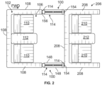
FIG. 2 is a plan view of two adjacent aircraft furniture structures; -
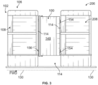
FIG. 3 is an elevational view of the aircraft furniture structures shown inFIG. 2 ; -
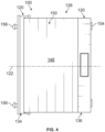
FIG. 4 is an elevational view of a door for a furniture structure illustrating an expanded position of the door; -
FIG. 5 is a partially cut-away elevational view of the door shown in FIG.; -
FIG. 6 is a partially cut-away elevational view of the door shown inFIGS. 4 and5 illustrating a partially-collapsed position of the door. -
FIG. 7 is an elevational view of the door shown inFIGS. 4-6 illustrating a collapsed position of the door; -
FIG. 8 is a plan view of the aircraft furniture structures shown inFIGS. 2 and3 illustrating the door in the collapsed position shown inFIG. 7 ; -
FIG. 9 is a plan view of the door illustrated inFIGS. 4-7 ; -
FIG. 10 is an enlarged view of a portion of the door illustrated inFIG. 9 ; -
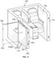
FIG. 11 is a perspective view of a door for a furniture structure; -
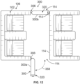
FIG. 12 is a plan view of the aircraft furniture structures shown inFIGS. 2 and3 illustrating the door shown inFIG. 11 in an open position. - Like reference numerals are used to designate like parts in the accompanying drawings.
- The detailed description provided below in connection with the appended drawings is intended as a description of the present examples and is not intended to represent the only forms in which the present examples are constructed or utilized. The description sets forth the functions of the examples and the sequence of operations for constructing and operating the examples. However, the same or equivalent functions and sequences may be accomplished by different examples.
- While various spatial and directional terms, such as "upper," "lower," "vertical," "horizontal," and/or the like are used to describe examples of the present application, it is understood that such terms are merely used with respect to the orientations shown in the drawings. The orientations can be inverted, rotated, or otherwise changed, such that, for example, an upper side becomes a lower side (or a left side becomes a right side) if the structure is flipped 180°, a left side becomes a front side (or a bottom or top becomes a side) if the structure is pivoted 90°, etc.
- Existing FAA Part 25 rules (25.813(e)) prohibit a door from being placed between a seated passenger and an emergency exit. Airline customers have requested mini suite designs with doors that violate this FAA rule. The FAA has issued Partial Grants of Exemption to this rule that include numerous conditions that must be complied with. For example, the door must be open and secured during taxi, take-off, and landing, and each mini suite must only be occupied by a single occupant. Existing suites have a permanently attached door, and although the door is controlled to be latched open and secured during taxi, take-off, and landing, the FAA requires an additional emergency egress path based on the assumption that the door latching device failed, and thus jammed the door closed, thereby impeding occupant egress out of the suite. Existing suite door designs are permanently secured/attached to the mini suite and are not collapsible. The examples described below are not limited to examples which solve any or all of the disadvantages of known suite doors.
- Certain examples disclosed herein provide a door for a furniture structure of a vehicle cabin. The door includes a frame configured to expand and collapse along a longitudinal axis of the door between a collapsed position and an expanded position. The door includes a cover extending over at least a portion of the frame.
- Certain examples disclosed herein provide a door for a furniture structure of a vehicle cabin. The door includes a frame configured to be removably mounted to the furniture structure such that the door is configured to be selectively mounted to and dismounted from the furniture structure.
- Certain examples disclosed herein provide a door for a furniture structure of a vehicle cabin. The door includes a frame configured to be rotatably mounted to the furniture structure such that the frame is configured to rotate relative to the furniture structure between an open position and a closed position. The frame is configured to be removably mounted to the furniture structure such that the door is configured to be selectively mounted to and dismounted from the furniture structure.
- Certain examples disclosed herein operate in an unconventional manner to provide a collapsible, removable, and/or storable door for a suite of a vehicle cabin (e.g., an aircraft cabin, etc.). In some examples, the door uses a pivoting brace mechanism (e.g., a frame, etc.) surrounded by two retractable flexible surfaces (e.g., that at least partially cover a pivoting frame, etc.). In some examples, the door is (e.g., relatively easily, etc.) collapsible using a retractor and a pivoting joint. In some examples, the door is rotatable relative to a furniture structure between an open position and a closed position.
- In some examples, the door is removable from the suite without requiring the use of one or more tools. In some examples, the removability of the door enables remote storage of the door within a closet, overhead storage bin, and/or the like. In some examples, the ability of the door to collapse facilitates remote storage of the door.
- By providing a door that is removable and/or remotely storable (e.g., during taxi, takeoff, landing, etc.), the mini suite no longer violates FAR 25.813(e). Therefore, dividers between two adjacent suites that are required to meet a design showing single occupancy are capable of being lowered and/or opened. The resultant configurations would then be treated on a regulatory basis similar to two first-class passenger seats in lieu of a mini suite with a door, and would therefore not be required to comply with the door exemptions. The removable and/or storable doors disclosed herein expand the evolution of the mini suite, for example by offering airline customers numerous options when configurating the passenger cabin.
-
FIGS. 1-3 illustrate perspective, plan, and aisle views, respectively, of afurniture structure 102 of a vehicle cabin. Referring toFIGS. 1-3 , an example of adoor 100 for thefurniture structure 102 of the vehicle cabin is provided. In the illustrated example, the vehicle cabin is an aircraft cabin and thefurniture structure 102 is anaircraft furniture structure 102. However, the door examples disclosed herein are not limited to aircraft, but rather are applicable to any type of vehicle, such as, but not limited to, automobiles, rail cars, marine vehicles (e.g., boats, submarines, catamarans, canoes, kayaks, etc.), and/or the like. For example, the doors disclosed herein may be used in the cabin (e.g., the passenger compartment, etc.) of an automobile, the cabin of a rail car, the cabin of a marine vehicle, etc. - In some examples including the illustrated example, the
furniture structure 102 includes a suite 106 (e.g., a mini suite, etc.) that includes asuite perimeter wall 108 and one or more seats 110 (not visible inFIG. 3 ) contained within thewall 108. Although twoseats 110 are shown, thesuite 106 may include any other number of seats 110 (e.g., a single, i.e., one, seat; three seats; four seats, etc.). some examples including illustrated example include an optional divider 112 (not visible inFIG. 3 ) between theseats 110. As shown inFIGS. 2 and3 , thesuite 106 is positioned adjacent another suite 206 (e.g., including awall 208,seats 210, anddivider 212, etc.) such that one or more accesses 114 (e.g., entrances, exits, etc.) is provided to enable access into and out of thesuit 106. Although twodoors 100 are shown, thesuite 106 may include any other number of doors 100 (e.g., a single, i.e., one, door; three doors; four doors, etc.). - In some examples , the
door 100 is collapsible, removable, and/or storable. For example, and referring now toFIGS. 4-7 , thedoor 100 includes aframe 120 that extends a length along alongitudinal axis 122. Theframe 120 is configured to expand and collapse along thelongitudinal axis 122 between acollapsed position 124 and an expanded (e.g., deployed, etc.)position 126. Thecollapsed position 124 of thedoor 100 is shown inFIG. 7 . The expandedposition 126 of thedoor 100 is shown inFIGS. 4 and5 .FIG. 6 illustrates a partially-collapsedposition 128 of thedoor 100. - As shown in
FIG. 8 , thecollapsed position 124 of the door 100 (e.g., of theframe 120, etc.) opens thecorresponding access 114 of thesuite 106 such that a passenger or other occupant of thesuite 106 can enter or exit thesuite 106. In the expandedposition 126 of the door 100 (e.g., of theframe 120, etc.) shown for example inFIGS. 2 and3 , thedoor 100 at least partially blocks thecorresponding access 114 of thesuite 106. In some examples, thedoor 100 provides a divider between adjacent suites (e.g., similar to a honeymoon suite, etc.). For instance, the illustrated example of thedoor 100 provides a divider between thesuites door 100 may be used as a divider, for example a divider wherein thelongitudinal axis 122 extends perpendicular or approximately perpendicular to a longitudinal axis 130 (FIG. 3 ) of the vehicle cabin, etc. - Referring to
FIGS. 5-7 , in the illustrated example, theframe 120 of thedoor 100 includes one or more braces 132. Thebrace 132 is configured to fold along a length thereof. For instance, in some examples including the illustrated example, theframe 120 includes first andsecond frame members brace 132 extending a length from thefirst frame member 134 to thesecond frame member 136, and vice versa. Thebrace 132 includes first andsecond end portions second frame members brace 132 includes twosegments brace 132 includes thehinge 146 extending between thefirst end portion 138 and the second end portion 140). Accordingly, thesegments hinge 146 such that thebrace 132 is collapsible along the length thereof. The ability of thebrace 132 to collapse enables theframe 120 to collapse along the longitudinal axis 122 (i.e., along the length) of theframe 120. Although two are shown, theframe 120 may include any other number of thebraces 132. - Optionally, the
first end portion 138 and/or thesecond end portion 140 of thebrace 132 is pivotally (e.g., hingedly, rotatably, etc.) mounted to thecorresponding frame member 134 and/or 136 using barrel mount and/or torsion hardware. In some examples, barrel mount and/or torsion hardware supports thebrace 132 vertically, for example to facilitate preventing thebrace 132 from buckling in the expandedposition 126 of thedoor 100. In some examples, thebrace 132 is a spring open parallel arm. Any other structure, component, mechanism, and/or the like may be additionally or alternatively used to pivotally mount thefirst end portion 138 and/or thesecond end portion 140 to thecorresponding frame member 134 and/or 136. - In addition or alternatively to the
brace 132, theframe member 134, theframe member 136, and/or the like, theframe 120 may include any other structure, component, mechanism, and/or the like that enables theframe 120 to expand and collapse between the expandedposition 126 and thecollapsed position 124. For example, thebrace 132 may include two or more of thehinges 146 such that thebrace 132 folds similar to an accordion, thebrace 132 may fold along the length thereof along a width direction (e.g., a direction perpendicular or approximately perpendicular to thelongitudinal axis 122, a direction into the page ofFIGS. 4-7 , etc.) in addition or alternatively to folding along thelongitudinal axis 122, etc. - In some examples, the
door 100 includes one ormore covers 148 that extend over at least a portion of theframe 120. Optionally, thecover 148 includes aflexible segment 150. Theflexible segment 150 of thecover 148 may be fabricated from any material(s), such as, but not limited to, a fabric, a sheet, plastic, a polymer, a fiber, a natural fiber, and/or the like. Although two are shown, thedoor 100 may include any other number of thecovers 148. - Referring now to
FIGS. 5-10 , to accommodate the expanding and collapsing function of theframe 120 between the expandedposition 126 and thecollapsed position 124, some examples of theframe 120 include a retractor mechanism (e.g., a roller blind mechanism, etc.) to expand and retract thecover 148 along with theframe 120. For instance, in the illustrated example of thecover 148 is mounted on acorresponding roller 152 and configured to retract at least partially around theroller 152 when theframe 120 is moved to thecollapsed position 124. For example, theflexible segment 150 of thecover 148 is configured to expand and retract (e.g., wind and unwind, etc.) on theroller 152 between a retracted position of the cover 148 (shown inFIGS. 7 and8 ) and an expanded (e.g., deployed, etc.) position of the cover 148 (shown inFIGS. 1-5 and9 ). When theframe 120 is moved from the expandedposition 126 to thecollapsed position 124, theflexible segment 150 of thecover 148 retracts to the retracted position of thecover 148, for example by winding around theroller 152. In some examples, the retractor mechanism (e.g., theroller 152, etc.) is spring-loaded such that thecover 148 is biased toward the retracted position of thecover 148. - In addition or alternatively to the
roller 152, the retractor mechanism, a roller blind mechanism, a spring-loaded mechanism, and/or the like, thecover 148 may include any other structure, component, mechanism, and/or the like that enables thedoor 100 to expand and collapse between the expandedposition 126 and thecollapsed position 124. For example, theflexible segment 150 of thecover 148 may fold along the length thereof (e.g., similar to an accordion, etc.), etc. - Referring to
FIGS. 2-7 , in some examples, thedoor 100 includes one or more mechanisms that facilitate releasably holding thedoor 100 in the expandedposition 126. For instance, the illustrated example includes one or moremagnetic components 154 that cooperate with a magnetic component of theother suite 206 to releasably hold thedoor 100 in the expandedposition 126 using magnetic force. In some examples, the magnetic component of theother suit 206 is defined by a portion of thewall 208, a discrete magnetic component is mounted to thewall 208, and/or the like. Although two are shown, thedoor 100 may include any number of themagnetic component 154. In addition or alternative to themagnetic component 154 and/ the magnetic component ofother suite 206, the mechanism that facilitates releasably holding thedoor 100 in the expandedposition 126 may include any other structure, component, mechanism, and/or the like that enables thedoor 100 to be releasably held in the expandedposition 126, such as, but not limited to, a quarter-turn fastener, a half-turn fastener, a snap-fit fastener, an interference-fit fastener, a threaded fastener, a latch, a pin, a clevis, a detent, a detent of thebrace 132, friction and/or stiction, friction and/or stiction within thebrace 132, a hook, a loop, an arm, and/or the like. - In some examples, and referring now to
FIGS. 2-10 , thedoor 100 is configured to be removably mounted to thefurniture structure 102, for example to enable thedoor 100 to be selectively mounted to and dismounted from thefurniture structure 102. For instance, the illustrated example of thedoor 100 is removably mounted to thesuite perimeter wall 108 of thesuite 106. In some examples including the illustrated example, theframe 120 of thedoor 100 includes one ormore connectors 156 configured to be removably connected to thefurniture structure 102. For example, theconnector 156 is configured to be removably connected to thesuite perimeter wall 108 to enable theframe 120 to be selectively mounted to and dismounted from thesuite perimeter wall 108. - Once dismounted (i.e., removed) from the
furniture structure 102, thedoor 100 can be remotely stored (e.g., within a closet, an overhead storage bin, etc.), for example with theframe 120 in thecollapsed position 124. In some examples, to remove and remotely store thedoor 100, thedoor 100 is collapsed, un-clipped from thesuite perimeter wall 108, and stowed away. In some examples, the ability of thedoor 100 to collapse facilitates remote storage of thedoor 100. - In the illustrated example, the
connector 156 includes abayonet fastener 156a (labeled inFIG. 9 ), for example a rotatable fitting, a twist fitting, a spring-loaded fitting, a keyhole fitting, etc. The illustrated example of theconnector 156 includes arelease button 156b (labeled inFIG. 9 ; e.g., a push button, a push bar, a push lever, a push latch, a pull bar, a pull lever, a pull latch, etc.) that enables a user to selectively release thebayonet fastener 156a from a complementary connector 158 (shown inFIG. 1 ; e.g., a receptacle, a keyhole, a slot, an opening, a recess, a detent, a depression, a female connector, etc.) of thefurniture structure 102. In addition or alternatively to thebayonet fastener 156a, therelease button 156b, and/or the illustratedcomplementary connector 158, theconnector 156 and/or thecomplementary connector 158 may include any other structure, component, mechanism, and/or the like that enables theconnector 156 to be removably connected to thefurniture structure 102, such as, but not limited to, a quarter-turn fastener, a half-turn fastener, a snap-fit fastener, an interference-fit fastener, a threaded fastener, a latch, a pin, a clevis, a slotted receptacle mating to keyhole, a detent, friction/stiction, a hook, a loop, an arm, and/or the like. - In addition or alternatively to the expanding and collapsing function of the
door 100, theframe 120 of thedoor 100 may be rotatably mounted to thefurniture structure 102 such that thedoor 100 is configured to rotate relative to thefurniture structure 102 between an open position and a closed position. For example,FIG. 11 illustrates adoor 300 that includes aframe 320 that is rotatably mounted to thefurniture structure 102 about ahinge 356 such that thedoor 300 rotates about the hinge 356 (e.g., along anarc 358, etc.) relative to thefurniture structure 102 between an open position (shown by dashed lines inFIG. 11 ) and a closed position (shown by solid lines inFIG. 11 ). - As shown in
FIG. 12 , the open position of thedoor 300a (e.g., of theframe 320, etc.) opens thecorresponding access 114 of thesuite 106 such that a passenger or other occupant of thesuite 106 can enter or exit thesuite 106 through theopen door 300a. In the closed position of thedoor 300b (e.g., of theframe 320, etc.), thedoor 300b at least partially blocks thecorresponding access 114 of thesuite 106, as is also illustrated inFIG. 12 . In some examples, thedoor 300 provides a divider between adjacent suites (e.g., similar to a honeymoon suite, etc.). - In some examples, the
door 300 is configured to be removably mounted to thefurniture structure 102, for example to enable thedoor 300 to be selectively mounted to and dismounted from thefurniture structure 102. For example, thedoor 300 may include a connector similar to the connector 156 (shown inFIGS. 2-10 ) that enables thedoor 300 to be selectively mounted to and dismounted from thefurniture structure 102, but that also includes the hinge 356 (and/or another rotating connection) to enable thedoor 100 to rotate between the open and closed positions, etc. - In some examples, a door for a furniture structure of a vehicle cabin includes a frame configured to expand and collapse along a longitudinal axis of the door between a collapsed position and an expanded position. The door includes a cover extending over at least a portion of the frame.
- The frame may include a brace that includes two segments connected together at a hinge. The frame may include a brace that is configured to fold along a length thereof.
- The frame may include first and second frame members and a brace extending a length between the first and second frame members. The brace may include first and second end portions that are pivotally mounted to the first and second frame members. The brace may include a hinge extending between the first and second end portions such that the brace is collapsible along the length thereof.
- The door may be configured to be removably mounted to the furniture structure.
- The frame may include a connector configured to be removably connected to the furniture structure.
- The frame may include a connector configured to be removably connected to the furniture structure. The connector may enable the frame to be selectively mounted to and dismounted from the furniture structure.
- The door may be configured to be remotely stored when the frame is in the collapsed position.
- The cover may include a flexible segment.
- The cover may be mounted on a roller and be configured to retract at least partially around the roller when the frame is moved to the collapsed position.
- The cover may be mounted on a roller and be configured to retract to a retracted position of the cover when the frame is moved to the collapsed position. The roller may be spring-loaded such that the cover is biased toward the retracted position of the cover.
- The door may be configured to at least partially block an access to a suite of the vehicle cabin in the expanded position of the frame.
- The door may be configured to open an access to a suite of the vehicle cabin in the collapsed position of the frame.
- The door may include a divider between adjacent suites of the vehicle cabin.
- In some examples, a door for a furniture structure of a vehicle cabin includes a frame configured to be rotatably mounted to the furniture structure such that the frame is configured to rotate relative to the furniture structure between an open position and a closed position. The frame is configured to be removably mounted to the furniture structure such that the door is configured to be selectively mounted to and dismounted from the furniture structure.
- The frame may include a connector configured to be removably connected to the furniture structure.
- The door may be configured to be remotely stored.
- The door may include a cover extending over at least a portion of the frame.
- The door may include a cover extending over at least a portion of the frame. The cover may include a flexible segment.
- The door may be configured to at least partially block an access to a suite of the vehicle cabin in the closed position of the frame.
- The door may be configured to open an access to a suite of the vehicle cabin in the open position of the frame.
- The door may include a divider between adjacent suites of the vehicle cabin.
- In some examples, a door is provided for a furniture structure of a vehicle cabin. The door includes a frame configured to be removably mounted to the furniture structure such that the door is configured to be selectively mounted to and dismounted from the furniture structure.
- As used herein, a structure, limitation, or element that is "configured to" perform a task or operation is particularly structurally formed, constructed, or adapted in a manner corresponding to the task or operation. For purposes of clarity and the avoidance of doubt, an object that is merely capable of being modified to perform the task or operation is not "configured to" perform the task or operation as used herein.
- Any range or value given herein can be extended or altered without losing the effect sought, as will be apparent to the skilled person.
- Although the subject matter has been described in language specific to structural features and/or methodological acts, it is to be understood that the subject matter defined in the appended claims is not necessarily limited to the specific features or acts described above. Rather, the specific features and acts described above are disclosed as example forms of implementing the claims.
- It will be understood that the benefits and advantages described above can relate to one example or can relate to several examples. The examples are not limited to those that solve any or all of the stated problems or those that have any or all of the stated benefits and advantages. It will further be understood that reference to 'an' item refers to one or more of those items.
- The order of execution or performance of the operations in examples of the present application illustrated and described herein is not essential, unless otherwise specified. That is, the operations can be performed in any order, unless otherwise specified, and examples of the application can include additional or fewer operations than those disclosed herein. For example, it is contemplated that executing or performing a particular operation before, contemporaneously with, or after another operation (e.g., different steps, etc.) is within the scope of the claims of the application.
- The term "comprising" is used in this specification to mean including the feature(s) or act(s) followed thereafter, without excluding the presence of one or more additional features or acts. The terms "comprising," "including," and "having" are intended to be inclusive and mean that there can be additional elements other than the listed elements. In other words, the use of "including," "comprising," "having," "containing," "involving," and variations thereof, is meant to encompass the items listed thereafter and additional items. Accordingly, and for example, unless explicitly stated to the contrary, examples "comprising" or "having" an element or a plurality of elements having a particular property can include additional elements not having that property. Further, references to "one example" or "an example" are not intended to be interpreted as excluding the existence of additional examples that also incorporate the recited features. The term "exemplary" is intended to mean "an example of'.
- When introducing elements of aspects of the application or the examples thereof, the articles "a," "an," "the," and "said" are intended to mean that there are one or more of the elements. In other words, the indefinite articles "a", "an", "the", and "said" as used in the specification and in the claims, unless clearly indicated to the contrary, should be understood to mean "at least one." Accordingly, and for example, as used herein, an element or step recited in the singular and preceded by the word "a" or "an" should be understood as not necessarily excluding the plural of the elements or steps.
- The phrase "one or more of the following: A, B, and C" means "at least one of A and/or at least one of B and/or at least one of C." The phrase "and/or", as used in the specification and in the claims, should be understood to mean "either or both" of the elements so conjoined, i.e., elements that are conjunctively present in some cases and disjunctively present in other cases. Multiple elements listed with "and/or" should be construed in the same fashion, i.e., "one or more" of the elements so conjoined. Other elements may optionally be present other than the elements specifically identified by the "and/or" clause, whether related or unrelated to those elements specifically identified. Thus, as a non-limiting example, a reference to "A and/or B", when used in conjunction with open-ended language such as "comprising" can refer, in one example, to A only (optionally including elements other than B); in another example, to B only (optionally including elements other than A); in yet another example, to both A and B (optionally including other elements); etc.
- As used in the specification and in the claims, "or" should be understood to have the same meaning as "and/or" as defined above. For example, when separating items in a list, "or" or "and/or" shall be interpreted as being inclusive, i.e., the inclusion of at least one, but also including more than one, of a number or list of elements, and, optionally, additional unlisted items. Only terms clearly indicated to the contrary, such as "only one of or "exactly one of," or, when used in the claims, "consisting of," will refer to the inclusion of exactly one element of a number or list of elements. In general, the term "or" as used shall only be interpreted as indicating exclusive alternatives (i.e. "one or the other but not both") when preceded by terms of exclusivity, such as "either," "one of "only one of or "exactly one of." "Consisting essentially of," when used in the claims, shall have its ordinary meaning as used in the field of patent law.
- As used in the specification and in the claims, the phrase "at least one," in reference to a list of one or more elements, should be understood to mean at least one element selected from any one or more of the elements in the list of elements, but not necessarily including at least one of each and every element specifically listed within the list of elements and not excluding any combinations of elements in the list of elements. This definition also allows that elements may optionally be present other than the elements specifically identified within the list of elements to which the phrase "at least one" refers, whether related or unrelated to those elements specifically identified. Thus, as a non-limiting example, "at least one of A and B" (or, equivalently, "at least one of A or B," or, equivalently "at least one of A and/or B") can refer, in one example, to at least one, optionally including more than one, A, with no B present (and optionally including elements other than B); in another example, to at least one, optionally including more than one, B, with no A present (and optionally including elements other than A); in yet another example, to at least one, optionally including more than one, A, and at least one, optionally including more than one, B (and optionally including other elements); etc.
- Use of ordinal terms such as "first," "second," "third," etc., in the claims to modify a claim element does not by itself connote any priority, precedence, or order of one claim element over another or the temporal order in which acts of a method are performed. Ordinal terms are used merely as labels to distinguish one claim element having a certain name from another element having a same name (but for use of the ordinal term), to distinguish the claim elements.
- Having described aspects of the application in detail, it will be apparent that modifications and variations are possible without departing from the scope of aspects of the appended claims. As various changes could be made in the above constructions, products, and methods without departing from the scope of the claims, it is intended that all matter contained in the above description and shown in the accompanying drawings shall be interpreted as illustrative and not in a limiting sense.
- It is to be understood that the above description is intended to be illustrative, and not restrictive. For example, the above-described examples (and/or features thereof) can be used in combination with each other. In addition, many modifications can be made to adapt a particular situation or material to the teachings of the various examples of the application without departing from the scope of the claims. While the dimensions and types of materials described herein are intended to define the parameters of the various examples of the application, the examples are by no means limiting and are examples. Many other examples will be apparent to those of ordinary skill in the art upon reviewing the above description. The scope of the various examples of the application should, therefore, be determined with reference to the appended claims. In the appended claims, the terms "including" and "in which" are used as the plain-English equivalents of the respective terms "comprising" and "wherein." Moreover, the terms "first," "second," and "third," etc. are used merely as labels, and are not intended to impose numerical requirements on their objects.
- This written description uses examples to disclose the various examples of the application, including the best mode, and also to enable any person of ordinary skill in the art to practice the various examples of the application, including making and using any devices or systems and performing any incorporated methods. The patentable scope of the various examples of the application is defined by the claims, and can include other examples that occur to those persons of ordinary skill in the art.
Claims (15)
- A door (100) for a furniture structure (102) of a vehicle cabin, the door (100) comprising:a frame (120) configured to expand and collapse along a longitudinal axis (122) of the door (100) between a collapsed position (124) and an expanded position (126); anda cover (148) extending over at least a portion of the frame (120).
- The door (100) of claim 1, wherein the frame (120) comprises a brace (132) that includes two segments (142, 144) connected together at a hinge (146).
- The door (100) of claim 1 or 2, wherein the frame (120) comprises a brace (132) that is configured to fold along a length thereof.
- The door (100) of any preceding claim, wherein the frame (120) comprises first and second frame members (134, 136) and a brace (132) extending a length between the first and second frame members (134, 136), the brace (132) comprising first and second end portions (138, 140) that are pivotally mounted to the first and second frame members (134, 136), the brace (132) comprising a hinge (146) extending between the first and second end portions (138, 140) such that the brace (132) is collapsible along the length thereof.
- The door (100) of any preceding claim, wherein the door (100) is configured to be removably mounted to the furniture structure (102).
- The door (100) of any preceding claim, wherein the frame (120) comprises a connector (156) configured to be removably connected to the furniture structure (102), the connector (156) enabling the frame (120) to be selectively mounted to and dismounted from the furniture structure (102).
- The door (100) of any preceding claim, wherein the door (100) is configured to be remotely stored when the frame (120) is in the collapsed position (120).
- The door (100) of any preceding claim, wherein the cover (148) comprises a flexible segment (150).
- The door (100) of any preceding claim, wherein the cover (148) is mounted on a roller and is configured to retract at least partially around the roller when the frame (120) is moved to the collapsed position (124).
- The door (100) of any preceding claim, wherein the cover (148) is mounted on a roller (152) and is configured to retract to a retracted position of the cover (148) when the frame (120) is moved to the collapsed position (124), the roller (152) being spring-loaded such that the cover (148) is biased toward the retracted position of the cover (148).
- A suite (106), optionally an aircraft cabin suite, comprising the door (100) of any preceding claim.
- The suite (106) of claim 11, wherein the door (100) is configured to at least partially block access (114) to the suite (106) in the expanded position (126) of the frame (120) and/or to open access (114) to the suite (106) in the collapsed position (124) of the frame (120).
- A vehicle cabin comprising the door of any of claims 1 to 10 or the suite (106) of either of claims 11 or 12.
- The vehicle cabin of claim 13, wherein the door (100) comprises a divider between adjacent suites (106) of the vehicle cabin.
- An aircraft comprising the vehicle cabin of claim 13 or 14.
Applications Claiming Priority (2)
| Application Number | Priority Date | Filing Date | Title |
|---|---|---|---|
| US202263382403P | 2022-11-04 | 2022-11-04 | |
| US18/327,002 US20240150004A1 (en) | 2022-11-04 | 2023-05-31 | Door for a vehicle cabin |
Publications (1)
| Publication Number | Publication Date |
|---|---|
| EP4368497A1 true EP4368497A1 (en) | 2024-05-15 |
Family
ID=88092851
Family Applications (1)
| Application Number | Title | Priority Date | Filing Date |
|---|---|---|---|
| EP23197627.5A Pending EP4368497A1 (en) | 2022-11-04 | 2023-09-15 | Door for a vehicle cabin |
Country Status (2)
| Country | Link |
|---|---|
| US (1) | US20240150004A1 (en) |
| EP (1) | EP4368497A1 (en) |
Families Citing this family (1)
| Publication number | Priority date | Publication date | Assignee | Title |
|---|---|---|---|---|
| US12473090B2 (en) * | 2023-06-28 | 2025-11-18 | The Boeing Company | Partition systems and methods for seat assemblies |
Citations (6)
| Publication number | Priority date | Publication date | Assignee | Title |
|---|---|---|---|---|
| GB1397901A (en) * | 1972-07-06 | 1975-06-18 | Hueppe Justin | Soundabsorbing partition member |
| WO2009139016A2 (en) * | 2008-05-16 | 2009-11-19 | Mix S.R.L. | Sliding door with variable dimensions |
| EP2871316A1 (en) * | 2013-11-11 | 2015-05-13 | Deal S.r.l. | Closing device with sliding door leaf |
| US20180281963A1 (en) * | 2017-04-04 | 2018-10-04 | Rockwell Collins, Inc. | Aircraft Door and Privacy Panel Assemblies |
| US20220106823A1 (en) * | 2019-03-08 | 2022-04-07 | Inventio Ag | Sliding door |
| US20220242571A1 (en) * | 2021-01-29 | 2022-08-04 | B/E Aerospace, Inc. | Actuatable door for an aircraft passenger suite |
Family Cites Families (8)
| Publication number | Priority date | Publication date | Assignee | Title |
|---|---|---|---|---|
| US5653278A (en) * | 1996-06-03 | 1997-08-05 | Cheng; Po-Wen | Automobile front and rear windshield sunshade device |
| US7052073B2 (en) * | 2003-04-07 | 2006-05-30 | Mitsui Mining & Smelting Co., Ltd. | Door apparatus |
| US8967225B2 (en) * | 2010-08-18 | 2015-03-03 | Won-Door Corporation | Leading end assemblies for movable partitions and related methods |
| US8544524B2 (en) * | 2011-06-21 | 2013-10-01 | Won-Door Corporation | Leading end assemblies for movable partitions including sensor assemblies, movable partition systems including sensor assemblies and related methods |
| US10131432B2 (en) * | 2015-04-07 | 2018-11-20 | B/E Aerospace, Inc. | Privacy divider for adjacent parallel passenger seats |
| US10124895B2 (en) * | 2015-04-09 | 2018-11-13 | B/E Aerospace, Inc. | Privacy panel with video monitor function for vehicle passenger seating unit |
| US20200385124A1 (en) * | 2019-06-10 | 2020-12-10 | B/E Aerospace, Inc. | Compact retractable partition |
| US12515606B2 (en) * | 2021-12-24 | 2026-01-06 | Ranger Design Inc. | Sliding door partition |
-
2023
- 2023-05-31 US US18/327,002 patent/US20240150004A1/en active Pending
- 2023-09-15 EP EP23197627.5A patent/EP4368497A1/en active Pending
Patent Citations (6)
| Publication number | Priority date | Publication date | Assignee | Title |
|---|---|---|---|---|
| GB1397901A (en) * | 1972-07-06 | 1975-06-18 | Hueppe Justin | Soundabsorbing partition member |
| WO2009139016A2 (en) * | 2008-05-16 | 2009-11-19 | Mix S.R.L. | Sliding door with variable dimensions |
| EP2871316A1 (en) * | 2013-11-11 | 2015-05-13 | Deal S.r.l. | Closing device with sliding door leaf |
| US20180281963A1 (en) * | 2017-04-04 | 2018-10-04 | Rockwell Collins, Inc. | Aircraft Door and Privacy Panel Assemblies |
| US20220106823A1 (en) * | 2019-03-08 | 2022-04-07 | Inventio Ag | Sliding door |
| US20220242571A1 (en) * | 2021-01-29 | 2022-08-04 | B/E Aerospace, Inc. | Actuatable door for an aircraft passenger suite |
Also Published As
| Publication number | Publication date |
|---|---|
| US20240150004A1 (en) | 2024-05-09 |
Similar Documents
| Publication | Publication Date | Title |
|---|---|---|
| US11827360B2 (en) | Slide-out tray table with interlock assembly | |
| US5273307A (en) | Lightweight, compact, erectable/collapsible wheeled seat | |
| EP3822113A1 (en) | Mini suite emergency egress solutions | |
| US10843799B2 (en) | Contoured class divider | |
| CN112389660B (en) | Extraction and retention system for a galley cart for a multi-cart bay | |
| CN110525662A (en) | Extensible separating system and method for seat-assembly | |
| EP4368497A1 (en) | Door for a vehicle cabin | |
| EP4217274B1 (en) | Slide-out tray table with interlock assembly | |
| US9090153B1 (en) | Rain shield for vehicle passengers | |
| EP3825231B1 (en) | Reconfigurable narrow galley cart for single-aisle aircraft | |
| DE102014203671A1 (en) | Luggage restraint system | |
| US11779172B2 (en) | Deployable transfer member for a lavatory | |
| DE102014203669B4 (en) | LUGGAGE RESTRAINT SYSTEM | |
| CN120270477A (en) | Dual folding barrier system and method for the flight deck of an aircraft | |
| DE102014203670A1 (en) | LUGGAGE RESTRAINT SYSTEM | |
| US11794657B2 (en) | Foldable vehicle cage system | |
| CN117985215A (en) | Doors for vehicle cabins | |
| KR102288892B1 (en) | Retractable table | |
| EP4541716A1 (en) | Multi location foldable bassinet | |
| JP6186254B2 (en) | Slope device for vehicle | |
| DE102005062000B4 (en) | Hat rack with roller blind | |
| US12351132B2 (en) | Collapsible vehicle interior console | |
| US12557920B2 (en) | Multi location foldable bassinet | |
| US20240123907A1 (en) | Systems, methods, and devices for seat trays | |
| CN223340512U (en) | Sleeper device for vehicle and vehicle |
Legal Events
| Date | Code | Title | Description |
|---|---|---|---|
| PUAI | Public reference made under article 153(3) epc to a published international application that has entered the european phase |
Free format text: ORIGINAL CODE: 0009012 |
|
| STAA | Information on the status of an ep patent application or granted ep patent |
Free format text: STATUS: THE APPLICATION HAS BEEN PUBLISHED |
|
| AK | Designated contracting states |
Kind code of ref document: A1 Designated state(s): AL AT BE BG CH CY CZ DE DK EE ES FI FR GB GR HR HU IE IS IT LI LT LU LV MC ME MK MT NL NO PL PT RO RS SE SI SK SM TR |
|
| STAA | Information on the status of an ep patent application or granted ep patent |
Free format text: STATUS: REQUEST FOR EXAMINATION WAS MADE |
|
| 17P | Request for examination filed |
Effective date: 20241112 |
|
| RBV | Designated contracting states (corrected) |
Designated state(s): AL AT BE BG CH CY CZ DE DK EE ES FI FR GB GR HR HU IE IS IT LI LT LU LV MC ME MK MT NL NO PL PT RO RS SE SI SK SM TR |
|
| STAA | Information on the status of an ep patent application or granted ep patent |
Free format text: STATUS: EXAMINATION IS IN PROGRESS |
|
| 17Q | First examination report despatched |
Effective date: 20250207 |