EP4368419A1 - System and method for auto-location of tires employing footprint length - Google Patents
System and method for auto-location of tires employing footprint length Download PDFInfo
- Publication number
- EP4368419A1 EP4368419A1 EP23208402.0A EP23208402A EP4368419A1 EP 4368419 A1 EP4368419 A1 EP 4368419A1 EP 23208402 A EP23208402 A EP 23208402A EP 4368419 A1 EP4368419 A1 EP 4368419A1
- Authority
- EP
- European Patent Office
- Prior art keywords
- tire
- vehicle
- sensor unit
- footprint length
- footprint
- Prior art date
- Legal status (The legal status is an assumption and is not a legal conclusion. Google has not performed a legal analysis and makes no representation as to the accuracy of the status listed.)
- Granted
Links
Images



Classifications
-
- B—PERFORMING OPERATIONS; TRANSPORTING
- B60—VEHICLES IN GENERAL
- B60C—VEHICLE TYRES; TYRE INFLATION; TYRE CHANGING; CONNECTING VALVES TO INFLATABLE ELASTIC BODIES IN GENERAL; DEVICES OR ARRANGEMENTS RELATED TO TYRES
- B60C23/00—Devices for measuring, signalling, controlling, or distributing tyre pressure or temperature, specially adapted for mounting on vehicles; Arrangement of tyre inflating devices on vehicles, e.g. of pumps or of tanks; Tyre cooling arrangements
- B60C23/02—Signalling devices actuated by tyre pressure
- B60C23/04—Signalling devices actuated by tyre pressure mounted on the wheel or tyre
- B60C23/0408—Signalling devices actuated by tyre pressure mounted on the wheel or tyre transmitting the signals by non-mechanical means from the wheel or tyre to a vehicle body mounted receiver
- B60C23/0415—Automatically identifying wheel mounted units, e.g. after replacement or exchange of wheels
- B60C23/0416—Automatically identifying wheel mounted units, e.g. after replacement or exchange of wheels allocating a corresponding wheel position on vehicle, e.g. front/left or rear/right
-
- B—PERFORMING OPERATIONS; TRANSPORTING
- B60—VEHICLES IN GENERAL
- B60C—VEHICLE TYRES; TYRE INFLATION; TYRE CHANGING; CONNECTING VALVES TO INFLATABLE ELASTIC BODIES IN GENERAL; DEVICES OR ARRANGEMENTS RELATED TO TYRES
- B60C23/00—Devices for measuring, signalling, controlling, or distributing tyre pressure or temperature, specially adapted for mounting on vehicles; Arrangement of tyre inflating devices on vehicles, e.g. of pumps or of tanks; Tyre cooling arrangements
- B60C23/02—Signalling devices actuated by tyre pressure
- B60C23/04—Signalling devices actuated by tyre pressure mounted on the wheel or tyre
- B60C23/0408—Signalling devices actuated by tyre pressure mounted on the wheel or tyre transmitting the signals by non-mechanical means from the wheel or tyre to a vehicle body mounted receiver
- B60C23/0415—Automatically identifying wheel mounted units, e.g. after replacement or exchange of wheels
-
- B—PERFORMING OPERATIONS; TRANSPORTING
- B60—VEHICLES IN GENERAL
- B60C—VEHICLE TYRES; TYRE INFLATION; TYRE CHANGING; CONNECTING VALVES TO INFLATABLE ELASTIC BODIES IN GENERAL; DEVICES OR ARRANGEMENTS RELATED TO TYRES
- B60C23/00—Devices for measuring, signalling, controlling, or distributing tyre pressure or temperature, specially adapted for mounting on vehicles; Arrangement of tyre inflating devices on vehicles, e.g. of pumps or of tanks; Tyre cooling arrangements
- B60C23/02—Signalling devices actuated by tyre pressure
- B60C23/04—Signalling devices actuated by tyre pressure mounted on the wheel or tyre
- B60C23/0486—Signalling devices actuated by tyre pressure mounted on the wheel or tyre comprising additional sensors in the wheel or tyre mounted monitoring device, e.g. movement sensors, microphones or earth magnetic field sensors
- B60C23/0488—Movement sensor, e.g. for sensing angular speed, acceleration or centripetal force
-
- B—PERFORMING OPERATIONS; TRANSPORTING
- B60—VEHICLES IN GENERAL
- B60C—VEHICLE TYRES; TYRE INFLATION; TYRE CHANGING; CONNECTING VALVES TO INFLATABLE ELASTIC BODIES IN GENERAL; DEVICES OR ARRANGEMENTS RELATED TO TYRES
- B60C23/00—Devices for measuring, signalling, controlling, or distributing tyre pressure or temperature, specially adapted for mounting on vehicles; Arrangement of tyre inflating devices on vehicles, e.g. of pumps or of tanks; Tyre cooling arrangements
- B60C23/06—Signalling devices actuated by deformation of the tyre, e.g. tyre mounted deformation sensors or indirect determination of tyre deformation based on wheel speed, wheel-centre to ground distance or inclination of wheel axle
- B60C23/064—Signalling devices actuated by deformation of the tyre, e.g. tyre mounted deformation sensors or indirect determination of tyre deformation based on wheel speed, wheel-centre to ground distance or inclination of wheel axle comprising tyre mounted deformation sensors, e.g. to determine road contact area
-
- G—PHYSICS
- G07—CHECKING-DEVICES
- G07C—TIME OR ATTENDANCE REGISTERS; REGISTERING OR INDICATING THE WORKING OF MACHINES; GENERATING RANDOM NUMBERS; VOTING OR LOTTERY APPARATUS; ARRANGEMENTS, SYSTEMS OR APPARATUS FOR CHECKING NOT PROVIDED FOR ELSEWHERE
- G07C5/00—Registering or indicating the working of vehicles
- G07C5/008—Registering or indicating the working of vehicles communicating information to a remotely located station
Definitions
- the invention relates generally to tire monitoring systems and methods. More particularly, the invention relates to systems and methods that include sensors mounted on vehicle tires to measure tire parameters. Specifically, the invention is directed to a system and method for locating the position of a tire on a vehicle by correlating a footprint length measured by a sensor mounted on the tire with an estimated footprint length of the tire.
- TPMS tire pressure monitoring systems
- a tire may have a TPMS sensor that transmits a pressure signal to a processor, which generates a low pressure warning when the pressure of the tire falls below a predetermined threshold. It is desirable that systems including pressure sensors be capable of identifying the specific tire that is experiencing low air pressure, rather than merely alerting the vehicle operator or a fleet manager that one of the vehicle tires is low in pressure.
- auto-location or localization The process of identifying which sensor sent a particular signal and, therefore, which tire may have low pressure, is referred to as auto-location or localization.
- Effective and efficient auto-location or localization is a challenge in TPMS, as tires may be replaced, rotated, and/or changed between summer and winter tires, altering the position of each tire on the vehicle. Additionally, power constraints typically make frequent sensor communications and auto-location or localization of signal transmissions impractical.
- LF low frequency
- RF radio frequency
- the invention relates to system in accordance with claim 1 and to a method in accordance with claim 15.
- an auto-location system for locating a position of a tire supporting a vehicle.
- the system includes a tire sensor unit that is mounted on the tire.
- the tire sensor unit includes a footprint length measurement sensor to measure a length of a footprint of the tire, and electronic memory capacity to store identification information for the tire sensor unit.
- a vehicle sensor unit is mounted on the vehicle and measures a lateral acceleration of the vehicle and a longitudinal acceleration of the vehicle.
- a processor is in electronic communication with the tire sensor unit and the vehicle sensor unit, and receives the measured footprint length, the identification information, the lateral acceleration, and the longitudinal acceleration.
- a virtual footprint length estimator is executed on the processor, and employs the lateral acceleration and the longitudinal acceleration to estimate a virtual footprint length of the tire.
- a correlation module is executed on the processor, and receives the virtual footprint length and the measured footprint length to generate correlation values.
- a decision arbitrator is executed on the processor. The decision arbitrator applies a set of decision rules to the correlation values to generate a wheel position indication that correlates the tire sensor unit to a position of the tire on the vehicle.
- ANN artificial neural network
- ANN neural networks are non-linear statistical data modeling tools used to model complex relationships between inputs and outputs or to find patterns in data.
- Axial and “axially” means lines or directions that are parallel to the axis of rotation of the tire.
- CAN bus is an abbreviation for controller area network.
- “Circumferential” means lines or directions extending along the perimeter of the surface of the annular tread perpendicular to the axial direction.
- Equatorial centerplane means the plane perpendicular to the tire's axis of rotation and passing through the center of the tread.
- “Footprint” means the contact patch or area of contact created by the tire tread with a flat surface as the tire rotates or rolls.
- Inboard side means the side of the tire nearest the vehicle when the tire is mounted on a wheel and the wheel is mounted on the vehicle.
- “Lateral” means an axial direction.
- Outboard side means the side of the tire farthest away from the vehicle when the tire is mounted on a wheel and the wheel is mounted on the vehicle.
- Ring and radially means directions radially toward or away from the axis of rotation of the tire.
- Thread element or “traction element” means a rib or a block element defined by a shape having adjacent grooves.
- an exemplary embodiment of an auto-location system 10 of the present invention is presented.
- the system 10 locates the position of each tire 12 supporting a vehicle 14.
- the position of each tire 12 on the vehicle 14 shall be referred to herein by way of example as front left position 12a, front right position 12b, rear left position 12c, and rear right position 12d.
- the vehicle 14 is depicted as a passenger car, the invention is not to be so restricted.
- the principles of the invention find application in other vehicle categories, such as commercial trucks, off-the-road vehicles, and the like, in which vehicles may be supported by more or fewer tires than those shown in Figure 1 .
- the tires 12 are of conventional construction, and each tire is mounted on a respective wheel 16 as known to those skilled in the art. Each tire 12 includes a pair of sidewalls 18 that extend to a circumferential tread 20. An innerliner 22 is disposed on the inner surface of the tire 12, and when the tire is mounted on the wheel 16, an internal cavity 24 is formed, which is filled with a pressurized fluid, such as air.
- a tire sensor unit 26 is attached to the innerliner 22 of each tire 12 by means such as an adhesive, and measures certain parameters or conditions of the tire as will be described in greater detail below. It is to be understood that the tire sensor unit 26 may be attached in such a manner, or to other components of the tire 12, such as on or in one of the sidewalls 18, on or in the tread 20, on the wheel 16, and/or a combination thereof. For the purpose of convenience, reference herein shall be made to mounting of the tire sensor unit 26 on the tire 12, with the understanding that such mounting includes all such types of attachment.
- a respective tire sensor unit 26 is mounted on each tire 12 for the purpose of detecting certain real-time tire parameters, such as tire pressure and tire temperature.
- the tire sensor unit 26 preferably includes a pressure sensor and a temperature sensor, and may be of any known configuration.
- the tire sensor unit 26 may be referred to as a tire pressure monitoring system (TPMS) sensor.
- the tire sensor unit 26 preferably also includes electronic memory capacity for storing identification (ID) information for the tire sensor unit, known as sensor ID information 92, which includes a unique identifying number or code for each tire sensor unit.
- ID information 92 identification information for the tire sensor unit
- the phrase tire ID is sometimes used interchangeably with sensor ID information 92, and reference herein shall be made to sensor ID information for the purpose of convenience.
- the tire sensor unit 26 ( Figure 1 ) preferably also measures a length 28 of a centerline 30 of a footprint 32 of the tire 12. More particularly, as the tire 12 contacts the ground, the area of contact created by the tread 20 with the ground is known as the footprint 32.
- the centerline 30 of the footprint 32 corresponds to the equatorial centerplane of the tire 12, which is the plane that is perpendicular to the axis of rotation of the tire and which passes through the center of the tread 20.
- the tire sensor unit 26 thus measures the length 28 of the centerline 30 of the tire footprint 32, which is referred to herein as the measured footprint length 28. Any suitable technique for measuring the measured footprint length 28 may be employed by the tire sensor unit 26.
- the tire sensor unit 26 may include a strain sensor or piezoelectric sensor that measures deformation of the tread 20 and thus indicates the measured footprint length 28.
- each measured footprint length 28 is associated with the sensor ID information 92 of the particular tire sensor unit 26 that obtained the measured footprint length.
- a vehicle sensor unit 34 preferably is mounted on the vehicle 14 to measure a lateral acceleration 36 of the vehicle and a longitudinal acceleration 38 of the vehicle.
- the vehicle sensor unit 34 may include a telematics unit that is equipped with an inertial measurement unit (IMU), which is attached to the vehicle 14 to measure the lateral acceleration 36 and longitudinal acceleration 38.
- IMU inertial measurement unit
- aspects of the auto-location system 10 preferably are executed on a processor 40.
- the processor 40 enables input of parameters and execution of specific techniques, to be described below, which are stored in a suitable storage medium and are in electronic communication with the processor.
- the processor 40 may be mounted on the vehicle 14, or may be a remote processor in a cloud-based server 44.
- the tire sensor unit 26 ( Figure 1 ) preferably includes wireless transmission means 42, such as an antenna, for wirelessly sending the measured footprint length 28 and the sensor ID information 92 to the processor 40.
- the vehicle sensor unit 34 ( Figure 4 ) preferably also includes wireless transmission means 42, such as an antenna, for wirelessly sending the lateral acceleration 36 and the longitudinal acceleration 38 to the processor 40.
- Output from the auto-location system 10 may be wirelessly transmitted by an antenna 46 from the processor 40 to a display device 50.
- the display device 50 may include a device that is accessible to a user of the vehicle 14 or a technician for the vehicle, such as a smartphone, and/or a device that is accessible to a fleet manager, such as a computer.
- Output from the auto-location system 10 may also be wirelessly transmitted from the processor 40 to an electronic control system 48 of the vehicle 14.
- the measured footprint length 28 is transmitted from the tire sensor unit 26 to the processor 40, and the lateral acceleration 36 and the longitudinal acceleration 38 are transmitted from the vehicle sensor unit 34 to the processor.
- the auto-location system 10 includes a virtual footprint length estimator 52, a correlation module 54, and a decision arbitrator 56 to generate a wheel position indication 58, as will be described in greater detail below.
- the footprint length estimator 52 is in electronic communication with and is executed on the processor 40.
- the vehicle acceleration data including the lateral acceleration 36 and the longitudinal acceleration 38, as measured over a predetermined window of time, are electronically communicated or transmitted to the footprint length estimator 52.
- the footprint length estimator 52 employs the lateral acceleration 36 and the longitudinal acceleration 38 to estimate a virtual footprint length 60 of the tire 12.
- the footprint length estimator 52 executes a vehicle dynamics model 62.
- the vehicle dynamics model 62 receives the lateral acceleration 36 and the longitudinal acceleration 38 as inputs and generates an estimate of the corresponding lateral and longitudinal load transfer of the vehicle 14, as well as an estimate of a total load 64 ( Figure 5 ) at each tire 12 of the vehicle 14.
- Exemplary vehicle dynamics models 62 are described in U.S. Patent Numbers 9,752,962 ; 9,663,115 ; and 9,222,854 .
- the virtual footprint length 60 of each tire 12 is generated.
- the virtual footprint length 60 is estimated with a regression model 66.
- a predetermined plot 68 of footprint length data 70 versus tire load data 72 is employed.
- the estimated tire load 64 from the vehicle dynamics model 62 is correlated in the plot 68 to determine the estimate of the virtual footprint length 60.
- the correlation module 54 which is in electronic communication with and is executed on the processor 40, receives the virtual footprint length 60 from the footprint length estimator 52 and the measured footprint length 28 as measured by the tire sensor unit 26.
- the correlation module 54 correlates a set of virtual footprint lengths 60 with a corresponding set of measured footprint lengths 28 for each tire 12 on the vehicle 14. More particularly, the correlation module 54 executes a statistical correlation of the virtual footprint length 60 for each of the front left 12a, front right 12b, rear left 12c, and rear right 12d tire positions with the measured footprint lengths 28 for each of the front left, front right, rear left, and rear right tire positions.
- an exemplary correlation between a plot line 74 for the virtual footprint length 60 of a tire 12 with a plot line 76 for the measured footprint length 28 of the tire is shown in a correlation plot 78.
- sixteen (16) total correlations preferably are performed, as the virtual footprint length 60 for each of the four (4) positions of front left 12a, front right 12b, rear left 12c, and rear right 12d is correlated with the measured footprint length 28 for each of the four (4) positions.
- the resulting correlation values 80 preferably are stored in a correlation matrix 82, which is stored on and/or is in electronic communication with the processor 40.
- the correlation matrix 82 is input into the decision arbitrator 56, which is in electronic communication with and is executed on the processor 40.
- the decision arbitrator 56 includes a set of decision rules 84 that are preferably applied in sequence to the correlation values 80 of the correlation matrix 82 to assign each respective tire sensor unit 26 to a tire mounting position of front left 12a, front right 12b, rear left 12c, and rear right 12d on the vehicle 14.
- each measured footprint length 28 is associated with the sensor ID information 92 of the particular tire sensor unit 26 that obtained the measured footprint length.
- the decision rules 84 preferably include a first rule 86 that identifies the left side positions 12a, 12c and the right side positions 12b, 12d.
- the decision arbitrator 56 compares the virtual footprint length 60 for the front left position 12a and the virtual footprint length for the rear left position 12c to the measured footprint lengths 28 in the correlation matrix 82.
- the measured footprint lengths 28 that yield a positive correlation with the virtual footprint length 60 for the front left position 12a and the virtual footprint length for the rear left position 12c enables the tire sensor units 26 for those measured footprint lengths, through the sensor ID information 92, to be designated as left side positions 94.
- the decision arbitrator 56 compares the virtual footprint length 60 for the front right position 12b and the virtual footprint length for the rear right position 12d to the measured footprint lengths 28 in the correlation matrix 82.
- the measured footprint lengths 28 that yield a positive correlation with the virtual footprint length 60 for the front right position 12b and the virtual footprint length for the rear right position 12d enables the tire sensor units 26 for those measured footprint lengths, through the sensor ID information 92, to be designated as right side positions 96.
- the decision rules 84 preferably include a second rule 88 that differentiates between the front left position 12a and the rear left position 12c.
- the decision arbitrator 56 compares the virtual footprint length 60 for the front left position 12a and the virtual footprint length for the rear left position 12c to the measured footprint lengths 28 of the designated left side positions 94.
- the tire sensor unit 26, through the sensor ID information 92, having the maximum correlation value in the Virtual FL row in the correlation matrix 82 is designated as the front left position 12a ID1, which is a first estimate for the identification of the tire 12 mounted in the front left position.
- the remaining tire sensor unit 26, through the sensor ID information 92 is designated as the rear left position 12c ID1, which is a first estimate for the identification of the tire 12 mounted in the rear left position.
- the tire sensor unit 26, through the sensor ID information 92, having the maximum correlation value in the Virtual RL row in the correlation matrix 82 is designated as the rear left position 12c ID2.
- the remaining tire sensor unit 26, through the sensor ID information 92, is designated as the front left position 12a ID2.
- the sensor ID information 92 for the tire sensor unit 26 designated in the front left position 12a is the same in the first estimate and the second estimate, that tire sensor unit is finally designated as the front left position, and the remaining tire sensor unit is finally designated as the rear left position 12c. If the sensor ID information 92 for the tire sensor unit 26 designated in the front left position 12a is not the same in the first estimate and the second estimate, a determination is made as to whether a difference between the maximum correlation value and the second highest correlation value in the Virtual FL row in the correlation matrix 82 is greater than a difference between the maximum correlation value and the second highest correlation value in the Virtual RL row. If it is greater, the designation of front left position 12a and rear left position 12c from the first estimate is used as the final designation. If it is less or equal, the designation of front left position 12a and rear left position 12c from the second estimate is used as the final designation.
- the decision rules 84 preferably include a third rule 90, which differentiates between the front right position 12b and the rear right position 12d.
- the decision arbitrator 56 compares the virtual footprint length 60 for the front right position 12b and the virtual footprint length for the rear right position 12d to the measured footprint lengths 28 of the designated right side positions 96.
- the tire sensor unit 26, through the sensor ID information 92, having the maximum correlation value in the Virtual FR row in the correlation matrix 82 is designated as the front right position 12b ID1, which is a first estimate for the identification of the tire 12 mounted in the front right position.
- the remaining tire sensor unit 26, through the sensor ID information 92 is designated as the rear right position 12d ID1, which is a first estimate for the identification of the tire 12 mounted in the rear right position.
- the tire sensor unit 26, through the sensor ID information 92, having the maximum correlation value in the Virtual RR row in the correlation matrix 82 is designated as the rear right position 12d ID2.
- the remaining tire sensor unit 26, through the sensor ID information 92, is designated as the front right position 12b ID2.
- the sensor ID information 92 for the tire sensor unit 26 designated in the front right position 12b is the same in the first estimate and the second estimate, that tire sensor unit is finally designated as the front right position, and the remaining tire sensor unit is finally designated as the rear right position 12d. If the sensor ID information 92 for the tire sensor unit 26 designated in the front right position 12b is not the same in the first estimate and the second estimate, a determination is made as to whether a difference between the maximum correlation value and the second highest correlation value in the Virtual FR row in the correlation matrix 82 is greater than a difference between the maximum correlation value and the second highest correlation value in the Virtual RR row. If it is greater, the designation of front right position 12b and rear right position 12d from the first estimate is used as the final designation. If it is less or equal, the designation of front right position 12b and rear right position 12d from the second estimate is used as the final designation.
- the decision rules 84 thus identify which tire sensor unit 26 is mounted in each respective position of front left 12a, front right 12b, rear left 12c, and rear right 12d on the vehicle 14, which is expressed as the wheel position indication 58.
- the wheel position indication 58 may be transmitted to a display device 50 and/or may be transmitted to an electronic control system 48 of the vehicle 14, as described above.
- the auto-location system 10 of the present invention employs correlation of a measured footprint length 28 as measured by a tire sensor unit 26 mounted on each tire 12 with an estimated footprint length 60 of the tire to identify the position of each tire sensor unit and thus each tire on the vehicle 14.
- the system 10 provides economical and accurate identification of the location of each tire 12 on the vehicle 14 with an approach that is agnostic as to the vehicle platform and/or tire identification numbers, such as stock keeping unit (SKU) numbers.
- SKU stock keeping unit
- the present invention also includes a method for locating the position of a tire 12 on a vehicle 14.
- the method includes steps in accordance with the description that is presented above and shown in Figures 1 through 8 .
Landscapes
- Engineering & Computer Science (AREA)
- Mechanical Engineering (AREA)
- Physics & Mathematics (AREA)
- General Physics & Mathematics (AREA)
- Tires In General (AREA)
Abstract
Description
- The invention relates generally to tire monitoring systems and methods. More particularly, the invention relates to systems and methods that include sensors mounted on vehicle tires to measure tire parameters. Specifically, the invention is directed to a system and method for locating the position of a tire on a vehicle by correlating a footprint length measured by a sensor mounted on the tire with an estimated footprint length of the tire.
- Sensors have been mounted on vehicle tires to monitor certain tire parameters, such as pressure and temperature. Systems that include sensors which monitor tire pressure are often known in the art as tire pressure monitoring systems (TPMS). For example, a tire may have a TPMS sensor that transmits a pressure signal to a processor, which generates a low pressure warning when the pressure of the tire falls below a predetermined threshold. It is desirable that systems including pressure sensors be capable of identifying the specific tire that is experiencing low air pressure, rather than merely alerting the vehicle operator or a fleet manager that one of the vehicle tires is low in pressure.
- The process of identifying which sensor sent a particular signal and, therefore, which tire may have low pressure, is referred to as auto-location or localization. Effective and efficient auto-location or localization is a challenge in TPMS, as tires may be replaced, rotated, and/or changed between summer and winter tires, altering the position of each tire on the vehicle. Additionally, power constraints typically make frequent sensor communications and auto-location or localization of signal transmissions impractical.
- Prior art techniques to achieve signal auto-location or localization have included various approaches. For example, low frequency (LF) transmitters have been installed in the vicinity of each tire, two-axis acceleration sensors have been employed to recognize a rotation direction of the tire for left or right tire location determination, and methods distinguishing front tires from rear tires using radio frequency (RF) signal strength have been used. The prior art techniques have deficiencies that make location of a sensor mounted in a tire on a vehicle either expensive or susceptible to inaccuracies. In addition, some prior art techniques may be undesirably complex and/or difficult to execute.
- As a result, there is a need in the art for a system that provides economical and accurate identification of the location of a position of a tire on a vehicle.
- The invention relates to system in accordance with
claim 1 and to a method in accordance with claim 15. - Dependent claims refer to preferred embodiments of the invention.
- According to an aspect of an exemplary embodiment of the invention, an auto-location system for locating a position of a tire supporting a vehicle is provided. The system includes a tire sensor unit that is mounted on the tire. The tire sensor unit includes a footprint length measurement sensor to measure a length of a footprint of the tire, and electronic memory capacity to store identification information for the tire sensor unit. A vehicle sensor unit is mounted on the vehicle and measures a lateral acceleration of the vehicle and a longitudinal acceleration of the vehicle. A processor is in electronic communication with the tire sensor unit and the vehicle sensor unit, and receives the measured footprint length, the identification information, the lateral acceleration, and the longitudinal acceleration. A virtual footprint length estimator is executed on the processor, and employs the lateral acceleration and the longitudinal acceleration to estimate a virtual footprint length of the tire. A correlation module is executed on the processor, and receives the virtual footprint length and the measured footprint length to generate correlation values. A decision arbitrator is executed on the processor. The decision arbitrator applies a set of decision rules to the correlation values to generate a wheel position indication that correlates the tire sensor unit to a position of the tire on the vehicle.
- The invention will be described by way of example and with reference to the accompanying drawings, in which:
-
Figure 1 is a schematic perspective view of a vehicle that includes tires employing an exemplary embodiment of the auto-location system of the present invention; -
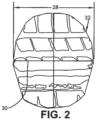
Figure 2 is a plan view of a footprint of a tire shown inFigure 1 ; -
Figure 3 is a schematic representation of data transmission to a cloud-based server and to a display device; -
Figure 4 is a schematic diagram of aspects of an exemplary embodiment of the auto-location system of the present invention; -
Figure 5 is a plot of a regression according to an aspect of the auto-location system shown inFigure 4 ; -
Figure 6 is a graphical representation of a correlation according to an aspect of the auto-location system shown inFigure 4 ; -
Figure 7 is a correlation matrix according to an aspect of the auto-location system shown inFigure 4 ; and -
Figure 8 is a schematic diagram of decision rules according to an aspect of the auto-location system shown inFigure 4 . - Similar numerals refer to similar parts throughout the drawings.
- "ANN" or "artificial neural network" is an adaptive tool for non-linear statistical data modeling that changes its structure based on external or internal information that flows through a network during a learning phase. ANN neural networks are non-linear statistical data modeling tools used to model complex relationships between inputs and outputs or to find patterns in data.
- "Axial" and "axially" means lines or directions that are parallel to the axis of rotation of the tire.
- "CAN bus" is an abbreviation for controller area network.
- "Circumferential" means lines or directions extending along the perimeter of the surface of the annular tread perpendicular to the axial direction.
- "Equatorial centerplane" means the plane perpendicular to the tire's axis of rotation and passing through the center of the tread.
- "Footprint" means the contact patch or area of contact created by the tire tread with a flat surface as the tire rotates or rolls.
- "Inboard side" means the side of the tire nearest the vehicle when the tire is mounted on a wheel and the wheel is mounted on the vehicle.
- "Lateral" means an axial direction.
- "Outboard side" means the side of the tire farthest away from the vehicle when the tire is mounted on a wheel and the wheel is mounted on the vehicle.
- "Radial" and "radially" means directions radially toward or away from the axis of rotation of the tire.
- "Tread element" or "traction element" means a rib or a block element defined by a shape having adjacent grooves.
- With reference to
Figures 1 through 8 , an exemplary embodiment of an auto-location system 10 of the present invention is presented. With particular reference toFigure 1 , thesystem 10 locates the position of eachtire 12 supporting avehicle 14. The position of eachtire 12 on thevehicle 14 shall be referred to herein by way of example as frontleft position 12a, frontright position 12b, rearleft position 12c, and rearright position 12d. While thevehicle 14 is depicted as a passenger car, the invention is not to be so restricted. The principles of the invention find application in other vehicle categories, such as commercial trucks, off-the-road vehicles, and the like, in which vehicles may be supported by more or fewer tires than those shown inFigure 1 . - The
tires 12 are of conventional construction, and each tire is mounted on arespective wheel 16 as known to those skilled in the art. Eachtire 12 includes a pair ofsidewalls 18 that extend to acircumferential tread 20. Aninnerliner 22 is disposed on the inner surface of thetire 12, and when the tire is mounted on thewheel 16, aninternal cavity 24 is formed, which is filled with a pressurized fluid, such as air. - A
tire sensor unit 26 is attached to theinnerliner 22 of eachtire 12 by means such as an adhesive, and measures certain parameters or conditions of the tire as will be described in greater detail below. It is to be understood that thetire sensor unit 26 may be attached in such a manner, or to other components of thetire 12, such as on or in one of thesidewalls 18, on or in thetread 20, on thewheel 16, and/or a combination thereof. For the purpose of convenience, reference herein shall be made to mounting of thetire sensor unit 26 on thetire 12, with the understanding that such mounting includes all such types of attachment. - A respective
tire sensor unit 26 is mounted on eachtire 12 for the purpose of detecting certain real-time tire parameters, such as tire pressure and tire temperature. For this reason, thetire sensor unit 26 preferably includes a pressure sensor and a temperature sensor, and may be of any known configuration. Thetire sensor unit 26 may be referred to as a tire pressure monitoring system (TPMS) sensor. Thetire sensor unit 26 preferably also includes electronic memory capacity for storing identification (ID) information for the tire sensor unit, known assensor ID information 92, which includes a unique identifying number or code for each tire sensor unit. In the art, the phrase tire ID is sometimes used interchangeably withsensor ID information 92, and reference herein shall be made to sensor ID information for the purpose of convenience. - Turning to
Figure 2 , the tire sensor unit 26 (Figure 1 ) preferably also measures alength 28 of acenterline 30 of afootprint 32 of thetire 12. More particularly, as thetire 12 contacts the ground, the area of contact created by thetread 20 with the ground is known as thefootprint 32. Thecenterline 30 of thefootprint 32 corresponds to the equatorial centerplane of thetire 12, which is the plane that is perpendicular to the axis of rotation of the tire and which passes through the center of thetread 20. Thetire sensor unit 26 thus measures thelength 28 of thecenterline 30 of thetire footprint 32, which is referred to herein as the measuredfootprint length 28. Any suitable technique for measuring the measuredfootprint length 28 may be employed by thetire sensor unit 26. For example, thetire sensor unit 26 may include a strain sensor or piezoelectric sensor that measures deformation of thetread 20 and thus indicates the measuredfootprint length 28. Preferably, each measuredfootprint length 28 is associated with thesensor ID information 92 of the particulartire sensor unit 26 that obtained the measured footprint length. - As shown in
Figure 4 , avehicle sensor unit 34 preferably is mounted on thevehicle 14 to measure alateral acceleration 36 of the vehicle and alongitudinal acceleration 38 of the vehicle. Thevehicle sensor unit 34 may include a telematics unit that is equipped with an inertial measurement unit (IMU), which is attached to thevehicle 14 to measure thelateral acceleration 36 andlongitudinal acceleration 38. - With reference to
Figure 3 , aspects of the auto-location system 10 preferably are executed on aprocessor 40. Theprocessor 40 enables input of parameters and execution of specific techniques, to be described below, which are stored in a suitable storage medium and are in electronic communication with the processor. Theprocessor 40 may be mounted on thevehicle 14, or may be a remote processor in a cloud-basedserver 44. - The tire sensor unit 26 (
Figure 1 ) preferably includes wireless transmission means 42, such as an antenna, for wirelessly sending the measuredfootprint length 28 and thesensor ID information 92 to theprocessor 40. The vehicle sensor unit 34 (Figure 4 ) preferably also includes wireless transmission means 42, such as an antenna, for wirelessly sending thelateral acceleration 36 and thelongitudinal acceleration 38 to theprocessor 40. - Output from the auto-
location system 10 may be wirelessly transmitted by anantenna 46 from theprocessor 40 to adisplay device 50. By way of example, thedisplay device 50 may include a device that is accessible to a user of thevehicle 14 or a technician for the vehicle, such as a smartphone, and/or a device that is accessible to a fleet manager, such as a computer. Output from the auto-location system 10 may also be wirelessly transmitted from theprocessor 40 to anelectronic control system 48 of thevehicle 14. - Turning to
Figure 4 , in the auto-location system 10, the measuredfootprint length 28 is transmitted from thetire sensor unit 26 to theprocessor 40, and thelateral acceleration 36 and thelongitudinal acceleration 38 are transmitted from thevehicle sensor unit 34 to the processor. The auto-location system 10 includes a virtualfootprint length estimator 52, acorrelation module 54, and adecision arbitrator 56 to generate awheel position indication 58, as will be described in greater detail below. - The
footprint length estimator 52 is in electronic communication with and is executed on theprocessor 40. The vehicle acceleration data, including thelateral acceleration 36 and thelongitudinal acceleration 38, as measured over a predetermined window of time, are electronically communicated or transmitted to thefootprint length estimator 52. Thefootprint length estimator 52 employs thelateral acceleration 36 and thelongitudinal acceleration 38 to estimate avirtual footprint length 60 of thetire 12. - To estimate the
virtual footprint length 60, thefootprint length estimator 52 executes avehicle dynamics model 62. Thevehicle dynamics model 62 receives thelateral acceleration 36 and thelongitudinal acceleration 38 as inputs and generates an estimate of the corresponding lateral and longitudinal load transfer of thevehicle 14, as well as an estimate of a total load 64 (Figure 5 ) at eachtire 12 of thevehicle 14. Exemplaryvehicle dynamics models 62 are described inU.S. Patent Numbers 9,752,962 9,663,115 9,222,854 - With additional reference to
Figure 5 , once the estimate of thetire load 64 is generated, thevirtual footprint length 60 of eachtire 12 is generated. Preferably, thevirtual footprint length 60 is estimated with aregression model 66. In theregression model 66, apredetermined plot 68 offootprint length data 70 versustire load data 72, which may be determined from earlier testing, is employed. The estimatedtire load 64 from thevehicle dynamics model 62 is correlated in theplot 68 to determine the estimate of thevirtual footprint length 60. - Returning to
Figure 4 , thecorrelation module 54, which is in electronic communication with and is executed on theprocessor 40, receives thevirtual footprint length 60 from thefootprint length estimator 52 and the measuredfootprint length 28 as measured by thetire sensor unit 26. Thecorrelation module 54 correlates a set ofvirtual footprint lengths 60 with a corresponding set of measuredfootprint lengths 28 for eachtire 12 on thevehicle 14. More particularly, thecorrelation module 54 executes a statistical correlation of thevirtual footprint length 60 for each of the front left 12a, front right 12b, rear left 12c, and rear right 12d tire positions with the measuredfootprint lengths 28 for each of the front left, front right, rear left, and rear right tire positions. - With additional reference to
Figures 6 and 7 , an exemplary correlation between aplot line 74 for thevirtual footprint length 60 of atire 12 with aplot line 76 for the measuredfootprint length 28 of the tire is shown in acorrelation plot 78. For avehicle 14 with four (4)tires 12, sixteen (16) total correlations preferably are performed, as thevirtual footprint length 60 for each of the four (4) positions of front left 12a, front right 12b, rear left 12c, and rear right 12d is correlated with the measuredfootprint length 28 for each of the four (4) positions. The resulting correlation values 80 preferably are stored in acorrelation matrix 82, which is stored on and/or is in electronic communication with theprocessor 40. - Referring to
Figures 4 and8 , thecorrelation matrix 82 is input into thedecision arbitrator 56, which is in electronic communication with and is executed on theprocessor 40. Thedecision arbitrator 56 includes a set of decision rules 84 that are preferably applied in sequence to the correlation values 80 of thecorrelation matrix 82 to assign each respectivetire sensor unit 26 to a tire mounting position of front left 12a, front right 12b, rear left 12c, and rear right 12d on thevehicle 14. As described above, each measuredfootprint length 28 is associated with thesensor ID information 92 of the particulartire sensor unit 26 that obtained the measured footprint length. - The decision rules 84 preferably include a
first rule 86 that identifies theleft side positions decision arbitrator 56 compares thevirtual footprint length 60 for the frontleft position 12a and the virtual footprint length for the rearleft position 12c to the measuredfootprint lengths 28 in thecorrelation matrix 82. The measuredfootprint lengths 28 that yield a positive correlation with thevirtual footprint length 60 for the frontleft position 12a and the virtual footprint length for the rearleft position 12c enables thetire sensor units 26 for those measured footprint lengths, through thesensor ID information 92, to be designated as left side positions 94. - The
decision arbitrator 56 compares thevirtual footprint length 60 for the frontright position 12b and the virtual footprint length for the rearright position 12d to the measuredfootprint lengths 28 in thecorrelation matrix 82. The measuredfootprint lengths 28 that yield a positive correlation with thevirtual footprint length 60 for the frontright position 12b and the virtual footprint length for the rearright position 12d enables thetire sensor units 26 for those measured footprint lengths, through thesensor ID information 92, to be designated as right side positions 96. - The decision rules 84 preferably include a
second rule 88 that differentiates between the frontleft position 12a and the rearleft position 12c. Thedecision arbitrator 56 compares thevirtual footprint length 60 for the frontleft position 12a and the virtual footprint length for the rearleft position 12c to the measuredfootprint lengths 28 of the designated left side positions 94. Thetire sensor unit 26, through thesensor ID information 92, having the maximum correlation value in the Virtual FL row in thecorrelation matrix 82 is designated as the frontleft position 12a ID1, which is a first estimate for the identification of thetire 12 mounted in the front left position. The remainingtire sensor unit 26, through thesensor ID information 92, is designated as the rearleft position 12c ID1, which is a first estimate for the identification of thetire 12 mounted in the rear left position. In a second estimate, thetire sensor unit 26, through thesensor ID information 92, having the maximum correlation value in the Virtual RL row in thecorrelation matrix 82 is designated as the rearleft position 12c ID2. The remainingtire sensor unit 26, through thesensor ID information 92, is designated as the frontleft position 12a ID2. - If the
sensor ID information 92 for thetire sensor unit 26 designated in the frontleft position 12a is the same in the first estimate and the second estimate, that tire sensor unit is finally designated as the front left position, and the remaining tire sensor unit is finally designated as the rearleft position 12c. If thesensor ID information 92 for thetire sensor unit 26 designated in the frontleft position 12a is not the same in the first estimate and the second estimate, a determination is made as to whether a difference between the maximum correlation value and the second highest correlation value in the Virtual FL row in thecorrelation matrix 82 is greater than a difference between the maximum correlation value and the second highest correlation value in the Virtual RL row. If it is greater, the designation of frontleft position 12a and rearleft position 12c from the first estimate is used as the final designation. If it is less or equal, the designation of frontleft position 12a and rearleft position 12c from the second estimate is used as the final designation. - The decision rules 84 preferably include a
third rule 90, which differentiates between the frontright position 12b and the rearright position 12d. Thedecision arbitrator 56 compares thevirtual footprint length 60 for the frontright position 12b and the virtual footprint length for the rearright position 12d to the measuredfootprint lengths 28 of the designated right side positions 96. Thetire sensor unit 26, through thesensor ID information 92, having the maximum correlation value in the Virtual FR row in thecorrelation matrix 82 is designated as the frontright position 12b ID1, which is a first estimate for the identification of thetire 12 mounted in the front right position. The remainingtire sensor unit 26, through thesensor ID information 92, is designated as the rearright position 12d ID1, which is a first estimate for the identification of thetire 12 mounted in the rear right position. In a second estimate, thetire sensor unit 26, through thesensor ID information 92, having the maximum correlation value in the Virtual RR row in thecorrelation matrix 82 is designated as the rearright position 12d ID2. The remainingtire sensor unit 26, through thesensor ID information 92, is designated as the frontright position 12b ID2. - If the
sensor ID information 92 for thetire sensor unit 26 designated in the frontright position 12b is the same in the first estimate and the second estimate, that tire sensor unit is finally designated as the front right position, and the remaining tire sensor unit is finally designated as the rearright position 12d. If thesensor ID information 92 for thetire sensor unit 26 designated in the frontright position 12b is not the same in the first estimate and the second estimate, a determination is made as to whether a difference between the maximum correlation value and the second highest correlation value in the Virtual FR row in thecorrelation matrix 82 is greater than a difference between the maximum correlation value and the second highest correlation value in the Virtual RR row. If it is greater, the designation of frontright position 12b and rearright position 12d from the first estimate is used as the final designation. If it is less or equal, the designation of frontright position 12b and rearright position 12d from the second estimate is used as the final designation. - The decision rules 84 thus identify which
tire sensor unit 26 is mounted in each respective position of front left 12a, front right 12b, rear left 12c, and rear right 12d on thevehicle 14, which is expressed as thewheel position indication 58. Thewheel position indication 58 may be transmitted to adisplay device 50 and/or may be transmitted to anelectronic control system 48 of thevehicle 14, as described above. - In this manner, the auto-
location system 10 of the present invention employs correlation of a measuredfootprint length 28 as measured by atire sensor unit 26 mounted on eachtire 12 with an estimatedfootprint length 60 of the tire to identify the position of each tire sensor unit and thus each tire on thevehicle 14. Thesystem 10 provides economical and accurate identification of the location of eachtire 12 on thevehicle 14 with an approach that is agnostic as to the vehicle platform and/or tire identification numbers, such as stock keeping unit (SKU) numbers. - The present invention also includes a method for locating the position of a
tire 12 on avehicle 14. The method includes steps in accordance with the description that is presented above and shown inFigures 1 through 8 . - It is to be understood that the structure and method of the above-described auto-location system may be altered or rearranged, or components or steps known to those skilled in the art omitted or added, without affecting the overall concept or operation of the invention. For example, electronic communication may be through a wired connection or wireless communication without affecting the overall concept or operation of the invention. Such wireless communications include radio frequency (RF) and Bluetooth® communications.
Claims (15)
- An auto-location system for locating a position of a tire supporting a vehicle, the system (10) comprising:a tire sensor unit (26) being mounted on the tire (12), the tire sensor unit (26) including a footprint length measurement sensor to measure a length of a footprint of the tire, and electronic memory capacity to store identification information for the tire sensor unit (26);a vehicle sensor unit (34) being mounted on the vehicle (14), the vehicle sensor unit (34) being configured to measure a lateral acceleration (36) of the vehicle and a longitudinal acceleration (38) of the vehicle;a processor (40) in electronic communication with the tire sensor unit (26) and the vehicle sensor unit (34), the processor (40) being configured to receive the measured footprint length, the identification information, the lateral acceleration, and the longitudinal acceleration;a virtual footprint length estimator (52) being configured for execution on the processor (40), the footprint length estimator being configured to employ the lateral acceleration and the longitudinal acceleration to estimate a virtual footprint length (60) of the tire;a correlation module (54) being configured for execution on the processor (40), the correlation module being configured to receive the virtual footprint length (60) and the measured footprint length to generate correlation values; anda decision arbitrator (56) being configured for execution on the processor (40), the decision arbitrator being configured to apply a set of decision rules (84) to the correlation values to generate a wheel position indication (58) that correlates the tire sensor unit (26) to a position of the tire (12a, 12b, 12c, 12d) on the vehicle (14).
- The auto-location system of claim 1, wherein the virtual footprint length estimator (52) is configured for execution of a vehicle dynamics model (62) in which the model receives the lateral acceleration and the longitudinal acceleration as inputs and generates an estimate of lateral and longitudinal load transfer of the vehicle (14) and an estimate of tire load, and, optionally, wherein the virtual footprint length (60) of the tire is estimated with a regression model once the estimate of tire load is generated.
- The auto-location system of claim 1 or 2, wherein the correlation module (54) is configured to correlate a set of virtual footprint lengths with a corresponding set of measured footprint lengths for each tire on the vehicle.
- The auto-location system of at least one of the previous claims, wherein the correlation values are stored in a correlation matrix (82).
- The auto-location system of at least one of the previous claims, wherein the decision rules (84) include a plurality of rules, and the decision arbitrator (56) applies the decision rules in sequence, and, optionally, wherein the decision rules include a first rule (86) that identifies left side positions on the vehicle and right side positions on the vehicle.
- The auto-location system of at least one of the previous claims, wherein the decision arbitrator (56) is configured to compare a virtual footprint length for a front left position and a virtual footprint length for a rear left position to measured footprint lengths in the correlation values, and, optionally, wherein tire sensor unit (26) generated measured footprint lengths that yield a positive correlation with the virtual footprint length for the front left position and the virtual footprint length for the rear left position are designated as left side positions.
- The auto-location system of at least one of the previous claims 1 to 5, wherein the decision arbitrator (56) is configured to compare a virtual footprint length for a front right position and a virtual footprint length for a rear right position to measured footprint lengths in the correlation values, and, optionally, wherein tire sensor unit (26) generated measured footprint lengths that yield a positive correlation with the virtual footprint length for the front right position and the virtual footprint length for the rear right position are designated as right side positions.
- The auto-location system of at least one of the previous claims, wherein the decision rules (84) include a second rule (88) that differentiates between a front left position and a rear left position.
- The auto-location system of at least one of the previous claims, wherein the decision arbitrator (56) is configured to compare a virtual footprint length for the front left position and a virtual footprint length for the rear left position to measured footprint lengths of the left side positions.
- The auto-location system of at least one of the previous claims, wherein the decision arbitrator (56) is configured to execute a first estimate among the correlation values to identify the tire mounted in at least one of the front left position and the rear left position, and, optionally, wherein the decision arbitrator (56) is configured to execute a second estimate among the correlation values to identify the tire mounted in at least one of the front left position and the rear left position.
- The auto-location system of at least one of the previous claims, wherein the decision rules (84) include a third rule (90) that differentiates between a front right position and a rear right position.
- The auto-location system of at least one of the previous claims, wherein the decision arbitrator (56) is configured to compare a virtual footprint length for the front right position and a virtual footprint length for the rear right position to measured footprint lengths of the right side positions.
- The auto-location system of at least one of the previous claims, wherein the decision arbitrator (56) is configured to execute a first estimate among the correlation values to identify the tire mounted in at least one of the front right position and the rear right position, and, optionally, wherein the decision arbitrator (56) is configured to execute a second estimate among the correlation values to identify the tire mounted in at least one of the front right position and the rear right position.
- The auto-location system of at least one of the previous claims, wherein the processor (40) is located in at least one of the vehicle (14) and a cloud-based server (44).
- A method for locating a position of a tire supporting a vehicle, the method preferably using a system (10) in accordance with at least one of the previous claims, the method comprising:mounting a tire sensor unit (26) on the tire (12), the tire sensor unit (26) including a footprint length measurement sensor to measure a length of a footprint of the tire, and electronic memory capacity to store identification information for the tire sensor unit (26);mounting a vehicle sensor (34) on the vehicle (14), the vehicle sensor unit (34) being configured to measure a lateral acceleration of the vehicle and a longitudinal acceleration of the vehicle (14);providing a processor (40) in electronic communication with the tire sensor unit (26) and the vehicle sensor unit (34), the processor (40) receiving the measured footprint length, the identification information, the lateral acceleration, and the longitudinal acceleration;providing a virtual footprint length estimator (52) executed on the processor (40), the footprint length estimator (52) employing the lateral acceleration and the longitudinal acceleration to estimate a virtual footprint length (60) of the tire (12);providing a correlation module (54) executed on the processor (40), the correlation module (54) receiving the virtual footprint length (60) and the measured footprint length to generate correlation values; andproviding a decision arbitrator (56) executed on the processor (40), the decision arbitrator (56) applying a set of decision rules (84) to the correlation values to generate a wheel position indication (58) that correlates the tire sensor unit (26) to a position of the tire (12a, 12b, 12c, 12d) on the vehicle (14).
Applications Claiming Priority (1)
| Application Number | Priority Date | Filing Date | Title |
|---|---|---|---|
| US202263382749P | 2022-11-08 | 2022-11-08 |
Publications (2)
| Publication Number | Publication Date |
|---|---|
| EP4368419A1 true EP4368419A1 (en) | 2024-05-15 |
| EP4368419B1 EP4368419B1 (en) | 2025-08-27 |
Family
ID=88745768
Family Applications (1)
| Application Number | Title | Priority Date | Filing Date |
|---|---|---|---|
| EP23208402.0A Active EP4368419B1 (en) | 2022-11-08 | 2023-11-07 | System and method for auto-location of tires employing footprint length |
Country Status (3)
| Country | Link |
|---|---|
| US (1) | US12344049B2 (en) |
| EP (1) | EP4368419B1 (en) |
| CN (1) | CN118003809A (en) |
Families Citing this family (1)
| Publication number | Priority date | Publication date | Assignee | Title |
|---|---|---|---|---|
| US20250187381A1 (en) * | 2023-12-12 | 2025-06-12 | The Goodyear Tire & Rubber Company | Wheel monitoring system and method |
Citations (6)
| Publication number | Priority date | Publication date | Assignee | Title |
|---|---|---|---|---|
| US20110153264A1 (en) * | 2009-12-09 | 2011-06-23 | Continental Automotive Gmbh | Location determination for individual tires of a multi-tire |
| US9222854B2 (en) | 2013-03-12 | 2015-12-29 | The Goodyear Tire & Rubber Company | Vehicle dynamic load estimation system and method |
| US9663115B2 (en) | 2015-10-09 | 2017-05-30 | The Goodyear Tire & Rubber Company | Method for estimating tire forces from CAN-bus accessible sensor inputs |
| US9752962B2 (en) | 2015-10-09 | 2017-09-05 | The Goodyear Tire & Rubber Company | Robust tire forces estimation system |
| US20210208028A1 (en) * | 2020-01-07 | 2021-07-08 | Continental Automotive Gmbh | Method for locating the position of each wheelset of a motor vehicle |
| US20220230481A1 (en) * | 2021-01-18 | 2022-07-21 | The Goodyear Tire & Rubber Company | System for auto-location of tires |
Family Cites Families (114)
| Publication number | Priority date | Publication date | Assignee | Title |
|---|---|---|---|---|
| US4157530A (en) | 1975-12-18 | 1979-06-05 | Merz Ernest J | Automatic tire pressure monitoring system |
| US4361202A (en) | 1979-06-15 | 1982-11-30 | Michael Minovitch | Automated road transportation system |
| US4936138A (en) | 1988-09-14 | 1990-06-26 | Oliver Rubber Company | Method and apparatus for tire inspection |
| DE4100472C1 (en) | 1991-01-09 | 1992-07-23 | Texas Instruments Deutschland Gmbh, 8050 Freising, De | |
| DE19740561A1 (en) | 1997-09-15 | 1999-03-18 | Siemens Ag | Subscription method especially for DECT system |
| US7839273B2 (en) | 2003-11-25 | 2010-11-23 | Joseph Akwo Tabe | Vehicle interactive electronic wireless air pressure system's information: “VIEW A PSI” |
| US7467034B2 (en) * | 2002-11-04 | 2008-12-16 | Automotive Technologies International, Inc. | Tire monitoring techniques |
| US6630885B2 (en) | 2000-07-26 | 2003-10-07 | Bridgestone/Firestone North American Tire, Llc | Electronic tire management system |
| US6463798B2 (en) | 2001-01-17 | 2002-10-15 | Microchip Technology Incorporated | Tire inflation pressure monitoring and location determining method and apparatus |
| US6571617B2 (en) | 2001-01-17 | 2003-06-03 | Microchip Technology Incorporated | Method and apparatus using directional antenna or learning modes for tire inflation pressure monitoring and location determination |
| WO2002057097A2 (en) | 2001-01-17 | 2002-07-25 | Microchip Technology Incorporated | Tire inflation pressure monitoring and location determining method and apparatus |
| DE10295892T5 (en) | 2001-02-20 | 2006-06-14 | Siemens Vdo Automotive Corporation, Auburn Hills | Combined tire pressure monitoring system and keyless entry system |
| US6489888B1 (en) | 2001-06-29 | 2002-12-03 | Johnson Controls Technology Company | Using signal strength to identify tire position |
| US8301108B2 (en) | 2002-11-04 | 2012-10-30 | Naboulsi Mouhamad A | Safety control system for vehicles |
| US7423532B2 (en) | 2001-10-29 | 2008-09-09 | Schrader Bridgeport International, Inc. | Determination of wheel sensor position using a single radio frequency detector in an automotive remote tire monitor system |
| US6725712B1 (en) | 2002-03-01 | 2004-04-27 | Lear Corporation | System and method for tire pressure monitoring with automatic tire location recognition |
| US7010968B2 (en) | 2002-04-18 | 2006-03-14 | Schrader Bridgeport International, Inc. | Determination of wheel sensor position using a wireless solution |
| US6952160B1 (en) | 2002-08-07 | 2005-10-04 | Ford Global Technologies, Llc | Method and apparatus, for identifying the location of pressure sensors in a tire pressure monitoring system |
| US6879252B2 (en) | 2002-11-14 | 2005-04-12 | Trw Inc. | Method and apparatus for associating tires with tire locations of a vehicle |
| CN1298555C (en) | 2003-01-22 | 2007-02-07 | 日产自动车株式会社 | Tire pressure monitoring apparatus and process |
| US6750761B1 (en) | 2003-02-25 | 2004-06-15 | Delphi Technologies, Inc. | Method for monitoring tire parameters |
| US7367227B2 (en) * | 2004-01-20 | 2008-05-06 | Schrader Bridgeport International | Determination of wheel sensor position using shock sensors and a wireless solution |
| DE102004006977B4 (en) | 2004-02-12 | 2005-12-08 | Siemens Ag | A method and apparatus for monitoring a physical quantity on a wheel of a vehicle |
| JP4483482B2 (en) | 2004-05-13 | 2010-06-16 | 株式会社デンソー | Position detecting device and tire air pressure detecting device having position detecting function |
| JP4175307B2 (en) | 2004-08-25 | 2008-11-05 | 株式会社デンソー | Tire pressure detector |
| US7355509B2 (en) | 2005-02-25 | 2008-04-08 | Iwapi Inc. | Smart modem device for vehicular and roadside applications |
| US7385485B2 (en) | 2005-03-18 | 2008-06-10 | Infineon Technologies Ag | Smart time tire monitoring system |
| GB0506087D0 (en) | 2005-03-24 | 2005-05-04 | Melexis Nv | Tyre pressure monitoring system |
| CN101115634A (en) | 2005-03-28 | 2008-01-30 | 米其林技术公司 | Automatic positioning of tire pressure monitoring system |
| CN101505979B (en) | 2006-05-17 | 2011-06-15 | Trw汽车美国有限责任公司 | Method and apparatus for determining identifiable tire locations in a tire pressure monitoring system |
| DE102006043505A1 (en) | 2006-05-22 | 2007-11-29 | Continental Teves Ag & Co. Ohg | Tire module and method for detecting wheel and / or tire condition sizes |
| JP4760640B2 (en) | 2006-09-19 | 2011-08-31 | 株式会社デンソー | Wheel position detecting device and tire air pressure detecting device having the same |
| US20080143507A1 (en) | 2006-10-23 | 2008-06-19 | Lear Corporation | Tire pressure monitoring system for associating tire pressure monitoring sensors with wheel locations on a vehicle |
| DE102006056965B4 (en) * | 2006-11-30 | 2008-09-04 | Continental Automotive Gmbh | Method for locating wheel electronics |
| US20080150712A1 (en) | 2006-12-21 | 2008-06-26 | Ford Global Technologies, Llc | Tire pressure monitoring (tpm) and remote keyless entry (rke) system |
| DE102007014765A1 (en) | 2007-03-28 | 2008-10-02 | Robert Bosch Gmbh | Method and device for monitoring operating parameters on tires |
| US8204645B2 (en) * | 2007-06-20 | 2012-06-19 | Compagnie Generale Des Etablissements Michelin | Self-learning autolocation of all tire ID's on a multi-axle vehicle |
| JP5101693B2 (en) * | 2007-06-20 | 2012-12-19 | コンパニー ゼネラール デ エタブリッスマン ミシュラン | Auto-location of all tire IDs for multi-axle vehicles |
| US20090002146A1 (en) | 2007-06-28 | 2009-01-01 | Trw Automotive U.S. Llc | Method and apparatus for determining and associating sensor location in a tire pressure monitoring system using dual antennas |
| US20090066498A1 (en) | 2007-09-07 | 2009-03-12 | Infineon Technologies Ag | Tire localization systems and methods |
| US7506540B1 (en) | 2008-02-22 | 2009-03-24 | Gm Global Technology Operations, Inc. | Autolocation of wireless tire pressure monitoring sensors |
| DE102008046271B3 (en) | 2008-09-08 | 2010-04-08 | Continental Automotive Gmbh | Method and measuring system for locating at least one wheel on a vehicle |
| DE102008049046A1 (en) | 2008-09-26 | 2010-04-08 | Continental Automotive Gmbh | Method, sensor, detector and system for locating at least one wheel on a vehicle |
| DE102009005904A1 (en) | 2009-01-23 | 2010-07-29 | Continental Automotive Gmbh | Method and device for continuously determining wheel state variables of a wheel |
| US8217776B2 (en) | 2009-02-19 | 2012-07-10 | Chrysler Group Llc | Tire pressure sensor location identification |
| US7986222B2 (en) | 2009-02-24 | 2011-07-26 | Infineon Technologies Ag | Tire position identification system and method |
| JP4709293B2 (en) | 2009-04-08 | 2011-06-22 | 株式会社豊田中央研究所 | Tire information monitoring device |
| WO2011038033A1 (en) | 2009-09-22 | 2011-03-31 | Schrader Electronics Ltd. | System and method for performing auto-location of a wheel in a vehicle using wheel phase angle information |
| US8332104B2 (en) * | 2009-09-22 | 2012-12-11 | Schrader Electronics Ltd. | System and method for performing auto-location of a tire pressure monitoring sensor arranged with a vehicle wheel |
| WO2011053809A1 (en) | 2009-10-30 | 2011-05-05 | Measurement Ltd. | Tire pressure monitoring system for motorcycles |
| DE102009059788B4 (en) * | 2009-12-21 | 2014-03-13 | Continental Automotive Gmbh | Method and device for locating the installation positions of vehicle wheels in a motor vehicle |
| US8446271B2 (en) | 2010-06-15 | 2013-05-21 | Honda Motor Co., Ltd. | Unique header format for TPMS and SMART entry system |
| US8584517B2 (en) * | 2010-06-21 | 2013-11-19 | Schrader Electronics Ltd | Load based wheel position determination |
| US8380460B2 (en) * | 2010-07-24 | 2013-02-19 | Ford Global Technologies, Llc | Method and system for distinguishing positions of tires in a dual rear tire vehicle |
| WO2012013726A1 (en) * | 2010-07-30 | 2012-02-02 | Schrader Electronics Limited | Tire pressure monitoring system with wheel position allocation through correlating with wheel rotation speed |
| US8498785B2 (en) | 2010-09-07 | 2013-07-30 | Trw Automotive U.S. Llc | Method and apparatus for determining tire position on a vehicle |
| US8436724B2 (en) * | 2010-11-05 | 2013-05-07 | Trw Automotive U.S. Llc | Method and apparatus for determining tire condition and location |
| US20120242502A1 (en) * | 2011-03-25 | 2012-09-27 | Infineon Technologies Ag | Wheel Unit, Central Unit and System for Localizing a Plurality of Wheels on a Vehicle |
| CN103502025B (en) | 2011-04-25 | 2016-05-04 | 日产自动车株式会社 | Tire air pressure dispensing device and tire air pressure surveillance |
| KR20130047341A (en) | 2011-10-31 | 2013-05-08 | 삼성전기주식회사 | Tire position detecting device and method thereof |
| US8396629B1 (en) | 2012-01-16 | 2013-03-12 | Samsung Electro-Mechanics Co., Ltd. | Device and method for detecting tire position |
| US8498759B1 (en) * | 2012-02-20 | 2013-07-30 | Trw Automotive U.S. Llc | Method and apparatus for determining a condition and relative location of an inner tire and an outer tire of a tire pair |
| WO2013134620A1 (en) | 2012-03-08 | 2013-09-12 | Husqvarna Ab | Automated operator-equipment pairing system and method |
| GB201205000D0 (en) | 2012-03-22 | 2012-05-09 | Schrader Electronics Ltd | System and method for momitoring vehicle load dynamics |
| US9469166B2 (en) | 2012-06-06 | 2016-10-18 | Continental Automotive Systems, Inc. | Apparatus and method for tire localization |
| KR20140001666A (en) | 2012-06-28 | 2014-01-07 | 삼성전기주식회사 | Tire location distinction device and tire location distinction method using the same |
| US10093137B2 (en) | 2012-08-27 | 2018-10-09 | Infineon Technologies Ag | Wheel localizer, wheel localization device, system, method and computer program for locating a position of a wheel |
| US9248708B2 (en) * | 2012-11-29 | 2016-02-02 | Continental Automotive Systems, Inc. | Localization with synchronized emissions for coupled wheels |
| US8843267B2 (en) | 2013-01-10 | 2014-09-23 | Infineon Technologies Ag | Wheel localizer, wheel localization device, system, method and computer program for locating a position of a wheel |
| DE102013101619A1 (en) * | 2013-02-19 | 2014-08-21 | Continental Reifen Deutschland Gmbh | Method for assigning tire positions to a vehicle with a tire pressure monitoring system |
| US9429463B2 (en) | 2013-03-04 | 2016-08-30 | International Road Dynamics, Inc. | System and method for measuring moving vehicle information using electrical time domain reflectometry |
| EP2981949B1 (en) | 2013-04-01 | 2018-11-14 | Tata Consultancy Services Ltd. | System and method for power effective participatory sensing |
| JP2015013637A (en) | 2013-06-03 | 2015-01-22 | 株式会社東海理化電機製作所 | Tire position determination system |
| US20140379231A1 (en) | 2013-06-24 | 2014-12-25 | Delphi Technologies, Inc. | System and method for automatic location assignment of wheels equipped with pressure sensors |
| TWI531490B (en) | 2013-08-20 | 2016-05-01 | Mobiletron Electronics Co Ltd | Code and its code method |
| DE102013220873A1 (en) * | 2013-10-15 | 2015-04-16 | Continental Automotive Gmbh | Method and arrangement for locating the installation position of wheels in a motor vehicle |
| US9278589B2 (en) | 2013-12-16 | 2016-03-08 | GM Global Technology Operations LLC | Low line TPMS: sensor association using RSSI and doppler signatures with a single or multiple ECUs |
| DE102014204862A1 (en) | 2014-03-17 | 2015-09-17 | Continental Automotive Gmbh | Method and device for locating the installation position of wheels in a vehicle |
| US9259978B2 (en) | 2014-06-30 | 2016-02-16 | Ford Global Technologies, Llc | Automatic wheel to tire pressure sensor correlation in distributed architecture |
| US20160039365A1 (en) | 2014-08-08 | 2016-02-11 | Johnson Controls Technology Company | Systems and Methods for Sending A Message From Tire Pressure Monitoring System to Body Electronics |
| TWI558579B (en) | 2014-10-01 | 2016-11-21 | 財團法人工業技術研究院 | Tire positioning method and tire positioning system |
| JP6338508B2 (en) | 2014-10-24 | 2018-06-06 | 日産自動車株式会社 | Tire pressure monitoring device, vehicle equipped with tire pressure monitoring device, and tire pressure monitoring method |
| FR3030373B1 (en) | 2014-12-17 | 2018-03-23 | Continental Automotive France | METHOD FOR ESTIMATING THE RELIABILITY OF WHEEL SENSOR MEASUREMENTS OF A VEHICLE AND SYSTEM FOR IMPLEMENTING SAID METHOD |
| JP6120018B2 (en) | 2015-01-22 | 2017-04-26 | トヨタ自動車株式会社 | Tire pressure monitoring device |
| JP6128137B2 (en) | 2015-02-06 | 2017-05-17 | トヨタ自動車株式会社 | Tire pressure sensor unit and tire pressure notification device |
| US9851227B2 (en) | 2015-03-03 | 2017-12-26 | Bendix Commercial Vehicle Systems Llc | TPMS sensor autolocation through low frequency programming |
| US10082381B2 (en) | 2015-04-30 | 2018-09-25 | Bebop Sensors, Inc. | Sensor systems integrated with vehicle tires |
| WO2017018700A1 (en) | 2015-07-28 | 2017-02-02 | Seetron Inc. | Tire pressure monitoring system and method for identifying position of tires |
| MX387584B (en) | 2015-10-08 | 2025-03-18 | Voxx Int Corp | SYSTEM AND METHOD OF MICRO-LOCATION AND COMMUNICATION WITH A PORTABLE VEHICLE CONTROL DEVICE. |
| US9522578B1 (en) * | 2015-11-11 | 2016-12-20 | The Goodyear Tire & Rubber Company | Robust system and method for auto-location of tire-based sensors |
| GB2545693B (en) | 2015-12-22 | 2020-05-20 | Schrader Electronics Ltd | Advanced tire monitoring system |
| JP2018016300A (en) | 2016-07-13 | 2018-02-01 | 株式会社デンソー | Wheel position detection device |
| KR101747375B1 (en) | 2016-09-12 | 2017-06-15 | 아이피랩 주식회사 | Apparatus and method for vehicle remote controlling and remote driving system |
| US10131320B2 (en) | 2016-09-27 | 2018-11-20 | Ford Global Technologies, Llc | Vehicle wheel anti-theft system and method |
| DE102016221430A1 (en) * | 2016-11-01 | 2018-05-03 | Continental Reifen Deutschland Gmbh | A method for assigning tire sensor modules to a trailer vehicle of their own commercial vehicle combination |
| US10093138B2 (en) | 2017-02-14 | 2018-10-09 | Ford Global Technologies, Llc | Monitoring tires of vehicles via personal area networks |
| US10685510B2 (en) | 2017-04-10 | 2020-06-16 | Oshkosh Corporation | Response vehicle systems and methods |
| US10237690B2 (en) | 2017-06-28 | 2019-03-19 | Nissan North America, Inc | Vehicle sensing and access control for on-demand services |
| US9950577B1 (en) | 2017-08-03 | 2018-04-24 | Continental Automotive Systems, Inc. | Method to localize physical positions of Bluetooth tire pressure monitoring sensors |
| US10479300B2 (en) | 2017-10-06 | 2019-11-19 | Ford Global Technologies, Llc | Monitoring of vehicle window vibrations for voice-command recognition |
| US10549587B2 (en) * | 2017-10-19 | 2020-02-04 | Infineon Technologies Ag | Method, component, tire-mounted TPMS module, TPMS system, and machine readable storage or computer program for determining time information of at least one contact patch event of a rolling tire, method for locating a tire |
| GB2567888B (en) | 2017-10-31 | 2020-09-30 | Schrader Electronics Ltd | Tire sensor location method and apparatus |
| WO2019092052A1 (en) | 2017-11-07 | 2019-05-16 | Trw Automotive Electronics & Components Gmbh | Vehicle tire pressure monitoring system and method for tire pressure monitoring of a vehicle |
| US10780749B2 (en) | 2017-11-21 | 2020-09-22 | Ford Global Technologies, Llc | Systems and methods for vehicle TPMS localization |
| CN108248303A (en) | 2018-01-19 | 2018-07-06 | 深圳市道通科技股份有限公司 | Tire location localization method, device and tire pressure monitoring system |
| US10442253B2 (en) | 2018-01-23 | 2019-10-15 | Infineon Technologies Ag | Tire pressure monitoring system (TPMS) module localization using bluetooth low energy beacons |
| US11562436B2 (en) | 2018-02-08 | 2023-01-24 | The Travelers Indemnity Company | Systems and methods for automated accident analysis |
| GB201810137D0 (en) | 2018-06-20 | 2018-08-08 | Continental Automotive Gmbh | A method for detecting wheel units of a vehicle and wheel mounting positions belonging to the wheel units, and a wheel information system |
| CN112672879B (en) | 2018-09-10 | 2023-06-20 | 法国圣-戈班玻璃公司 | Intelligent vehicle control system with integrated window glass |
| US20200101802A1 (en) | 2018-09-27 | 2020-04-02 | GM Global Technology Operations LLC | Advanced tire pressure monitoring system with software autolearn |
| US12114229B2 (en) | 2018-12-12 | 2024-10-08 | Qualcomm Incorporated | Systems and methods for location reporting with low latency for wireless networks |
| CN119272876A (en) | 2019-03-15 | 2025-01-07 | 3M创新有限公司 | Identify the causal model used to control the environment |
| EP3741587B1 (en) | 2019-05-23 | 2023-09-27 | Melexis Technologies SA | Auto-location using tire mounted system |
| US11376899B2 (en) | 2019-06-24 | 2022-07-05 | Infineon Technologies Ag | Structure borne sound for TPMS localization and communication |
-
2023
- 2023-11-07 US US18/503,607 patent/US12344049B2/en active Active
- 2023-11-07 EP EP23208402.0A patent/EP4368419B1/en active Active
- 2023-11-08 CN CN202311487493.1A patent/CN118003809A/en active Pending
Patent Citations (6)
| Publication number | Priority date | Publication date | Assignee | Title |
|---|---|---|---|---|
| US20110153264A1 (en) * | 2009-12-09 | 2011-06-23 | Continental Automotive Gmbh | Location determination for individual tires of a multi-tire |
| US9222854B2 (en) | 2013-03-12 | 2015-12-29 | The Goodyear Tire & Rubber Company | Vehicle dynamic load estimation system and method |
| US9663115B2 (en) | 2015-10-09 | 2017-05-30 | The Goodyear Tire & Rubber Company | Method for estimating tire forces from CAN-bus accessible sensor inputs |
| US9752962B2 (en) | 2015-10-09 | 2017-09-05 | The Goodyear Tire & Rubber Company | Robust tire forces estimation system |
| US20210208028A1 (en) * | 2020-01-07 | 2021-07-08 | Continental Automotive Gmbh | Method for locating the position of each wheelset of a motor vehicle |
| US20220230481A1 (en) * | 2021-01-18 | 2022-07-21 | The Goodyear Tire & Rubber Company | System for auto-location of tires |
Also Published As
| Publication number | Publication date |
|---|---|
| CN118003809A (en) | 2024-05-10 |
| EP4368419B1 (en) | 2025-08-27 |
| US12344049B2 (en) | 2025-07-01 |
| US20240149622A1 (en) | 2024-05-09 |
Similar Documents
| Publication | Publication Date | Title |
|---|---|---|
| EP4029707B1 (en) | System and method for auto-location of tires | |
| EP3378679B1 (en) | Model based tire wear estimation system and method | |
| EP3785943B1 (en) | Tire wear state estimation system and method employing footprint length | |
| US9874496B2 (en) | Tire suspension fusion system for estimation of tire deflection and tire load | |
| EP3858690B1 (en) | Method for estimating tire grip | |
| EP4112335B1 (en) | Tire pressure monitoring system and method employing axle cross comparison | |
| EP3957501B1 (en) | Tire high temperature forecasting system and method | |
| EP3785942B1 (en) | Method for extracting changes in tire characteristics | |
| EP4197822B1 (en) | Tire replacement system and method | |
| EP3785944B1 (en) | Tire wear state estimation system and method employing footprint shape factor | |
| US8886395B2 (en) | Dynamic tire slip angle estimation system and method | |
| EP4190596B1 (en) | Tire irregular wear detection system and method | |
| CN115519942B (en) | Tire Replacement Prediction System and Method | |
| EP3168067B1 (en) | Robust system and method for auto-location of tire-based sensors | |
| EP4368419B1 (en) | System and method for auto-location of tires employing footprint length | |
| US20250381805A1 (en) | System for auto-location of tires | |
| EP4385767B1 (en) | System and method for auto-location of tires employing footprint length | |
| EP4379346B1 (en) | Tire rolling resistance estimation system and method | |
| EP4385762B1 (en) | System and method for estimation of tire tread depth employing wheel speed | |
| EP4151436B1 (en) | Counter-deflection load estimation system and method | |
| US20260044693A1 (en) | Method for reading information contained in an rfid chip embedded in a vehicle tire | |
| CN118182021A (en) | System for automatically positioning tire by utilizing print length |
Legal Events
| Date | Code | Title | Description |
|---|---|---|---|
| PUAI | Public reference made under article 153(3) epc to a published international application that has entered the european phase |
Free format text: ORIGINAL CODE: 0009012 |
|
| STAA | Information on the status of an ep patent application or granted ep patent |
Free format text: STATUS: THE APPLICATION HAS BEEN PUBLISHED |
|
| AK | Designated contracting states |
Kind code of ref document: A1 Designated state(s): AL AT BE BG CH CY CZ DE DK EE ES FI FR GB GR HR HU IE IS IT LI LT LU LV MC ME MK MT NL NO PL PT RO RS SE SI SK SM TR |
|
| STAA | Information on the status of an ep patent application or granted ep patent |
Free format text: STATUS: REQUEST FOR EXAMINATION WAS MADE |
|
| 17P | Request for examination filed |
Effective date: 20241115 |
|
| RBV | Designated contracting states (corrected) |
Designated state(s): AL AT BE BG CH CY CZ DE DK EE ES FI FR GB GR HR HU IE IS IT LI LT LU LV MC ME MK MT NL NO PL PT RO RS SE SI SK SM TR |
|
| GRAP | Despatch of communication of intention to grant a patent |
Free format text: ORIGINAL CODE: EPIDOSNIGR1 |
|
| STAA | Information on the status of an ep patent application or granted ep patent |
Free format text: STATUS: GRANT OF PATENT IS INTENDED |
|
| RIC1 | Information provided on ipc code assigned before grant |
Ipc: B60C 23/06 20060101ALI20250307BHEP Ipc: B60C 23/04 20060101AFI20250307BHEP |
|
| INTG | Intention to grant announced |
Effective date: 20250407 |
|
| GRAS | Grant fee paid |
Free format text: ORIGINAL CODE: EPIDOSNIGR3 |
|
| GRAA | (expected) grant |
Free format text: ORIGINAL CODE: 0009210 |
|
| STAA | Information on the status of an ep patent application or granted ep patent |
Free format text: STATUS: THE PATENT HAS BEEN GRANTED |
|
| AK | Designated contracting states |
Kind code of ref document: B1 Designated state(s): AL AT BE BG CH CY CZ DE DK EE ES FI FR GB GR HR HU IE IS IT LI LT LU LV MC ME MK MT NL NO PL PT RO RS SE SI SK SM TR |
|
| REG | Reference to a national code |
Ref country code: CH Ref legal event code: EP |
|
| REG | Reference to a national code |
Ref country code: DE Ref legal event code: R096 Ref document number: 602023006098 Country of ref document: DE |
|
| REG | Reference to a national code |
Ref country code: IE Ref legal event code: FG4D |
|
| REG | Reference to a national code |
Ref country code: NL Ref legal event code: MP Effective date: 20250827 |
|
| PG25 | Lapsed in a contracting state [announced via postgrant information from national office to epo] |
Ref country code: IS Free format text: LAPSE BECAUSE OF FAILURE TO SUBMIT A TRANSLATION OF THE DESCRIPTION OR TO PAY THE FEE WITHIN THE PRESCRIBED TIME-LIMIT Effective date: 20251227 |
|
| PGFP | Annual fee paid to national office [announced via postgrant information from national office to epo] |
Ref country code: DE Payment date: 20251022 Year of fee payment: 3 |
|
| PG25 | Lapsed in a contracting state [announced via postgrant information from national office to epo] |
Ref country code: NO Free format text: LAPSE BECAUSE OF FAILURE TO SUBMIT A TRANSLATION OF THE DESCRIPTION OR TO PAY THE FEE WITHIN THE PRESCRIBED TIME-LIMIT Effective date: 20251127 |
|
| REG | Reference to a national code |
Ref country code: LT Ref legal event code: MG9D |
|
| PG25 | Lapsed in a contracting state [announced via postgrant information from national office to epo] |
Ref country code: PT Free format text: LAPSE BECAUSE OF FAILURE TO SUBMIT A TRANSLATION OF THE DESCRIPTION OR TO PAY THE FEE WITHIN THE PRESCRIBED TIME-LIMIT Effective date: 20251229 |
|
| PG25 | Lapsed in a contracting state [announced via postgrant information from national office to epo] |
Ref country code: FI Free format text: LAPSE BECAUSE OF FAILURE TO SUBMIT A TRANSLATION OF THE DESCRIPTION OR TO PAY THE FEE WITHIN THE PRESCRIBED TIME-LIMIT Effective date: 20250827 |
|
| PG25 | Lapsed in a contracting state [announced via postgrant information from national office to epo] |
Ref country code: HR Free format text: LAPSE BECAUSE OF FAILURE TO SUBMIT A TRANSLATION OF THE DESCRIPTION OR TO PAY THE FEE WITHIN THE PRESCRIBED TIME-LIMIT Effective date: 20250827 Ref country code: NL Free format text: LAPSE BECAUSE OF FAILURE TO SUBMIT A TRANSLATION OF THE DESCRIPTION OR TO PAY THE FEE WITHIN THE PRESCRIBED TIME-LIMIT Effective date: 20250827 |
|
| PGFP | Annual fee paid to national office [announced via postgrant information from national office to epo] |
Ref country code: FR Payment date: 20251023 Year of fee payment: 3 |
|
| PG25 | Lapsed in a contracting state [announced via postgrant information from national office to epo] |
Ref country code: GR Free format text: LAPSE BECAUSE OF FAILURE TO SUBMIT A TRANSLATION OF THE DESCRIPTION OR TO PAY THE FEE WITHIN THE PRESCRIBED TIME-LIMIT Effective date: 20251128 |
|
| PG25 | Lapsed in a contracting state [announced via postgrant information from national office to epo] |
Ref country code: SE Free format text: LAPSE BECAUSE OF FAILURE TO SUBMIT A TRANSLATION OF THE DESCRIPTION OR TO PAY THE FEE WITHIN THE PRESCRIBED TIME-LIMIT Effective date: 20250827 |
|
| PG25 | Lapsed in a contracting state [announced via postgrant information from national office to epo] |
Ref country code: LV Free format text: LAPSE BECAUSE OF FAILURE TO SUBMIT A TRANSLATION OF THE DESCRIPTION OR TO PAY THE FEE WITHIN THE PRESCRIBED TIME-LIMIT Effective date: 20250827 |
|
| PG25 | Lapsed in a contracting state [announced via postgrant information from national office to epo] |
Ref country code: BG Free format text: LAPSE BECAUSE OF FAILURE TO SUBMIT A TRANSLATION OF THE DESCRIPTION OR TO PAY THE FEE WITHIN THE PRESCRIBED TIME-LIMIT Effective date: 20250827 Ref country code: PL Free format text: LAPSE BECAUSE OF FAILURE TO SUBMIT A TRANSLATION OF THE DESCRIPTION OR TO PAY THE FEE WITHIN THE PRESCRIBED TIME-LIMIT Effective date: 20250827 |
|
| PG25 | Lapsed in a contracting state [announced via postgrant information from national office to epo] |
Ref country code: RS Free format text: LAPSE BECAUSE OF FAILURE TO SUBMIT A TRANSLATION OF THE DESCRIPTION OR TO PAY THE FEE WITHIN THE PRESCRIBED TIME-LIMIT Effective date: 20251127 |
|
| PG25 | Lapsed in a contracting state [announced via postgrant information from national office to epo] |
Ref country code: ES Free format text: LAPSE BECAUSE OF FAILURE TO SUBMIT A TRANSLATION OF THE DESCRIPTION OR TO PAY THE FEE WITHIN THE PRESCRIBED TIME-LIMIT Effective date: 20250827 |
|
| REG | Reference to a national code |
Ref country code: AT Ref legal event code: MK05 Ref document number: 1829613 Country of ref document: AT Kind code of ref document: T Effective date: 20250827 |
|
| PG25 | Lapsed in a contracting state [announced via postgrant information from national office to epo] |
Ref country code: RO Free format text: LAPSE BECAUSE OF FAILURE TO SUBMIT A TRANSLATION OF THE DESCRIPTION OR TO PAY THE FEE WITHIN THE PRESCRIBED TIME-LIMIT Effective date: 20250827 |
|
| PG25 | Lapsed in a contracting state [announced via postgrant information from national office to epo] |
Ref country code: SM Free format text: LAPSE BECAUSE OF FAILURE TO SUBMIT A TRANSLATION OF THE DESCRIPTION OR TO PAY THE FEE WITHIN THE PRESCRIBED TIME-LIMIT Effective date: 20250827 |
|
| PG25 | Lapsed in a contracting state [announced via postgrant information from national office to epo] |
Ref country code: DK Free format text: LAPSE BECAUSE OF FAILURE TO SUBMIT A TRANSLATION OF THE DESCRIPTION OR TO PAY THE FEE WITHIN THE PRESCRIBED TIME-LIMIT Effective date: 20250827 |
|
| PG25 | Lapsed in a contracting state [announced via postgrant information from national office to epo] |
Ref country code: AT Free format text: LAPSE BECAUSE OF FAILURE TO SUBMIT A TRANSLATION OF THE DESCRIPTION OR TO PAY THE FEE WITHIN THE PRESCRIBED TIME-LIMIT Effective date: 20250827 |
|
| PG25 | Lapsed in a contracting state [announced via postgrant information from national office to epo] |
Ref country code: IT Free format text: LAPSE BECAUSE OF FAILURE TO SUBMIT A TRANSLATION OF THE DESCRIPTION OR TO PAY THE FEE WITHIN THE PRESCRIBED TIME-LIMIT Effective date: 20250827 |
|
| PG25 | Lapsed in a contracting state [announced via postgrant information from national office to epo] |
Ref country code: CZ Free format text: LAPSE BECAUSE OF FAILURE TO SUBMIT A TRANSLATION OF THE DESCRIPTION OR TO PAY THE FEE WITHIN THE PRESCRIBED TIME-LIMIT Effective date: 20250827 |
|
| PG25 | Lapsed in a contracting state [announced via postgrant information from national office to epo] |
Ref country code: SK Free format text: LAPSE BECAUSE OF FAILURE TO SUBMIT A TRANSLATION OF THE DESCRIPTION OR TO PAY THE FEE WITHIN THE PRESCRIBED TIME-LIMIT Effective date: 20250827 Ref country code: EE Free format text: LAPSE BECAUSE OF FAILURE TO SUBMIT A TRANSLATION OF THE DESCRIPTION OR TO PAY THE FEE WITHIN THE PRESCRIBED TIME-LIMIT Effective date: 20250827 |
|
| REG | Reference to a national code |
Ref country code: DE Ref legal event code: R097 Ref document number: 602023006098 Country of ref document: DE |
|
| PG25 | Lapsed in a contracting state [announced via postgrant information from national office to epo] |
Ref country code: LT Free format text: LAPSE BECAUSE OF FAILURE TO SUBMIT A TRANSLATION OF THE DESCRIPTION OR TO PAY THE FEE WITHIN THE PRESCRIBED TIME-LIMIT Effective date: 20250827 Ref country code: MC Free format text: LAPSE BECAUSE OF FAILURE TO SUBMIT A TRANSLATION OF THE DESCRIPTION OR TO PAY THE FEE WITHIN THE PRESCRIBED TIME-LIMIT Effective date: 20250827 |
|
| PLBE | No opposition filed within time limit |
Free format text: ORIGINAL CODE: 0009261 |
|
| STAA | Information on the status of an ep patent application or granted ep patent |
Free format text: STATUS: NO OPPOSITION FILED WITHIN TIME LIMIT |
|
| REG | Reference to a national code |
Ref country code: CH Ref legal event code: L10 Free format text: ST27 STATUS EVENT CODE: U-0-0-L10-L00 (AS PROVIDED BY THE NATIONAL OFFICE) Effective date: 20260708 |
|
| PG25 | Lapsed in a contracting state [announced via postgrant information from national office to epo] |
Ref country code: LU Free format text: LAPSE BECAUSE OF NON-PAYMENT OF DUE FEES Effective date: 20251107 |
|
| 26N | No opposition filed |
Effective date: 20260528 |