EP4368344A1 - Centering a washer to a fastener element during installation - Google Patents
Centering a washer to a fastener element during installation Download PDFInfo
- Publication number
- EP4368344A1 EP4368344A1 EP23208847.6A EP23208847A EP4368344A1 EP 4368344 A1 EP4368344 A1 EP 4368344A1 EP 23208847 A EP23208847 A EP 23208847A EP 4368344 A1 EP4368344 A1 EP 4368344A1
- Authority
- EP
- European Patent Office
- Prior art keywords
- washer
- socket
- fastener
- socket device
- component
- Prior art date
- Legal status (The legal status is an assumption and is not a legal conclusion. Google has not performed a legal analysis and makes no representation as to the accuracy of the status listed.)
- Pending
Links
Images




Classifications
-
- B—PERFORMING OPERATIONS; TRANSPORTING
- B25—HAND TOOLS; PORTABLE POWER-DRIVEN TOOLS; MANIPULATORS
- B25B—TOOLS OR BENCH DEVICES NOT OTHERWISE PROVIDED FOR, FOR FASTENING, CONNECTING, DISENGAGING, OR HOLDING
- B25B13/00—Spanners; Wrenches
- B25B13/48—Spanners; Wrenches for special purposes
-
- B—PERFORMING OPERATIONS; TRANSPORTING
- B25—HAND TOOLS; PORTABLE POWER-DRIVEN TOOLS; MANIPULATORS
- B25B—TOOLS OR BENCH DEVICES NOT OTHERWISE PROVIDED FOR, FOR FASTENING, CONNECTING, DISENGAGING, OR HOLDING
- B25B13/00—Spanners; Wrenches
- B25B13/02—Spanners; Wrenches with rigid jaws
- B25B13/06—Spanners; Wrenches with rigid jaws of socket type
-
- B—PERFORMING OPERATIONS; TRANSPORTING
- B25—HAND TOOLS; PORTABLE POWER-DRIVEN TOOLS; MANIPULATORS
- B25B—TOOLS OR BENCH DEVICES NOT OTHERWISE PROVIDED FOR, FOR FASTENING, CONNECTING, DISENGAGING, OR HOLDING
- B25B27/00—Hand tools, specially adapted for fitting together or separating parts or objects whether or not involving some deformation, not otherwise provided for
- B25B27/0085—Hand tools, specially adapted for fitting together or separating parts or objects whether or not involving some deformation, not otherwise provided for explosive-powered
-
- F—MECHANICAL ENGINEERING; LIGHTING; HEATING; WEAPONS; BLASTING
- F02—COMBUSTION ENGINES; HOT-GAS OR COMBUSTION-PRODUCT ENGINE PLANTS
- F02C—GAS-TURBINE PLANTS; AIR INTAKES FOR JET-PROPULSION PLANTS; CONTROLLING FUEL SUPPLY IN AIR-BREATHING JET-PROPULSION PLANTS
- F02C7/00—Features, components parts, details or accessories, not provided for in, or of interest apart form groups F02C1/00 - F02C6/00; Air intakes for jet-propulsion plants
- F02C7/20—Mounting or supporting of plant; Accommodating heat expansion or creep
-
- F—MECHANICAL ENGINEERING; LIGHTING; HEATING; WEAPONS; BLASTING
- F16—ENGINEERING ELEMENTS AND UNITS; GENERAL MEASURES FOR PRODUCING AND MAINTAINING EFFECTIVE FUNCTIONING OF MACHINES OR INSTALLATIONS; THERMAL INSULATION IN GENERAL
- F16B—DEVICES FOR FASTENING OR SECURING CONSTRUCTIONAL ELEMENTS OR MACHINE PARTS TOGETHER, e.g. NAILS, BOLTS, CIRCLIPS, CLAMPS, CLIPS OR WEDGES; JOINTS OR JOINTING
- F16B43/00—Washers or equivalent devices; Other devices for supporting bolt-heads or nuts
-
- F—MECHANICAL ENGINEERING; LIGHTING; HEATING; WEAPONS; BLASTING
- F05—INDEXING SCHEMES RELATING TO ENGINES OR PUMPS IN VARIOUS SUBCLASSES OF CLASSES F01-F04
- F05D—INDEXING SCHEME FOR ASPECTS RELATING TO NON-POSITIVE-DISPLACEMENT MACHINES OR ENGINES, GAS-TURBINES OR JET-PROPULSION PLANTS
- F05D2230/00—Manufacture
- F05D2230/60—Assembly methods
-
- F—MECHANICAL ENGINEERING; LIGHTING; HEATING; WEAPONS; BLASTING
- F05—INDEXING SCHEMES RELATING TO ENGINES OR PUMPS IN VARIOUS SUBCLASSES OF CLASSES F01-F04
- F05D—INDEXING SCHEME FOR ASPECTS RELATING TO NON-POSITIVE-DISPLACEMENT MACHINES OR ENGINES, GAS-TURBINES OR JET-PROPULSION PLANTS
- F05D2260/00—Function
- F05D2260/30—Retaining components in desired mutual position
- F05D2260/31—Retaining bolts or nuts
Definitions
- This disclosure relates generally to a mechanical joint between components and, more particularly, to securing the components together using one or more fastener assemblies with washers.
- a structure of a gas turbine engine may include components bolted together at a joint.
- a washer may be arranged between a head of a bolt and the components. While the bolt is tightened and torqued to specification, rotation of the bolt head may cause the washer to skew to a side of the bolt head. Skewing between the washer and the bolt head may have a negative impact on pressure loading / distribution onto an adjacent component. Furthermore, skewing between the washer and the bolt head may induce a rotational imbalance where the structure is a (e.g., high speed) rotating structure of the gas turbine engine.
- a rotational imbalance where the structure is a (e.g., high speed) rotating structure of the gas turbine engine.
- an assembly method is provided during which a first component is arranged with a second component.
- the first component is secured to the second component using a fastener assembly.
- the fastener assembly includes a fastener element and a washer.
- the fastener element includes a wrenching feature.
- the washer has a full-hoop annular body with a cylindrical outer surface.
- the securing includes: mating a socket device with the fastener element and the washer, the socket device engaging the wrenching feature and the cylindrical outer surface; and rotating the fastener element about an axis using the socket device to tighten the fastener assembly and clamp the washer axially between the first component and the fastener element.
- the socket device centers the washer to the fastener element during the rotating.
- a first component is arranged with a second component.
- the first component is secured to the second component using a fastener assembly.
- the fastener assembly includes a bolt and a washer.
- the bolt includes a bolt head with a wrenching feature.
- the washer has an outer surface.
- the securing includes: mating a socket device with the bolt head and the washer, the socket device engaging the wrenching feature and the outer surface; and rotating the bolt head about an axis using the socket device to tighten the fastener assembly and clamp the washer axially between the first component and the bolt head.
- the socket device maintains the washer coaxial with the bolt during the rotating.
- a socket device includes a socket and a socket adaptor.
- the socket includes an axial end and a receptacle with a polygonal cross-sectional geometry.
- the receptacle projects axially along an axis into the socket from the axial end.
- the socket is configured to receive a fastener element within the receptacle.
- the fastener element is a bolt head or a nut.
- the socket adaptor includes a centering sleeve and a sleeve mount.
- the centering sleeve includes an inner surface and forms a counterbore at the axial end of the socket.
- the centering sleeve is configured to receive a washer within the counterbore.
- the centering sleeve projects radially inward to the inner surface.
- the inner surface is configured to radially engage the washer.
- the inner surface has a uniform radius to the axis as the inner surface extends circumferentially about the axis.
- the sleeve mount circumscribes the socket and mounts the centering sleeve to the socket.
- the centering sleeve may have a full-hoop annular geometry.
- the inner surface may be a cylindrical inner surface.
- the socket adaptor may also include a plurality of fingers arranged circumferentially about the axis. Each of the fingers may include a respective circumferential section of the centering sleeve.
- the outer surface may be a cylindrical outer surface of the washer.
- the socket device may include a cylindrical inner surface.
- the cylindrical inner surface may circumscribe and may be radially adjacent the cylindrical outer surface.
- the socket device may include a plurality of arcuate surfaces.
- the arcuate surfaces may be arranged circumferentially around and may be radially adjacent the cylindrical outer surface.
- the socket device may include a counterbore at an axial end of the socket device.
- the washer may be seated in the counterbore.
- the socket device may also include a receptacle with a polygonal cross-sectional geometry.
- the receptacle may project axially into the socket device from the counterbore.
- the receptacle may receive the wrenching feature.
- the socket device may include a centering sleeve.
- the centering sleeve may extend circumferentially around the washer and may radially engage the cylindrical outer surface.
- the centering sleeve may be circumferentially segmented.
- the centering sleeve may have a full-hoop annular geometry.
- the socket device may also include a socket that mates with the wrenching feature.
- the socket device may be configured as a monolithic body.
- the socket device may also include a socket and a sleeve mount.
- the socket may mate with the wrenching feature.
- the sleeve mount may circumscribe the socket.
- the sleeve mount may mount the centering sleeve to the socket.
- An outer diameter of the cylindrical outer surface may be equal to or greater than a largest outer lateral width of the fastener element.
- An outer diameter of the cylindrical outer surface may be less than a largest outer lateral width of the fastener element.
- the fastener element may be configured as or otherwise include a bolt head.
- the fastener element may be configured as or otherwise include a nut.
- the first component may include a first mount.
- the second component may include a second mount abutted against the first mount.
- the fastener assembly may secure the first mount to the second mount.
- a gas turbine engine rotating structure may include the first component, the second component and the fastener assembly.
- the present disclosure may include any one or more of the individual features disclosed above and/or below alone or in any combination thereof.
- FIG. 1 illustrates a tool 20 for use in securing components 22 and 24 of a structure 26 together at a joint with one or more fastener assemblies 28 (one fastener assembly shown in FIG. 1 ).
- the tool 20 of FIG. 1 includes a driver 30 and a socket device 32.
- the driver 30 include, but are not limited to, a manual rachet, a power rachet (e.g., an electrically or pneumatically powered impact wrench) or any other device capable of driving rotation of the socket device 32 about an axis 34, which axis 34 may be a centerline axis and/or a rotational axis of the socket device 32 and/or the respective fastener assembly 28.
- the socket device 32 of FIG. 1 is configured to operatively couple the driver 30 to a fastener element 36 of the respective fastener assembly 28.
- the driver 30 may thereby drive rotation of the fastener element 36 about the axis 34 through the socket device 32 by driving rotation of the socket device 32 about the axis 34.
- the fastener element 36 of FIG. 1 may be described herein as a head 38 of a fastener 40; e.g., a bolt.
- the fastener element 36 may alternatively be a nut 42 threaded onto a shank 44 of the fastener 40 of FIG. 1 (or another type of fastener such as threaded stud).
- the washer 46 is also configured to center a washer 46 of the respective fastener assembly 28 with the fastener element 36 (e.g., the bolt head) as the fastener element 36 is rotated about the axis 34.
- the washer 46 may be described herein as a regular washer. However, it is contemplated the washer 46 may alternatively be a lock washer or any other type of washer which would benefit from centering as described herein.
- the socket device 32 extends axially along the axis 34 between and to a first (e.g., tool side) end 48 of the socket device 32 and a second (e.g., fastener side) end 50 of the socket device 32.
- the socket device 32 includes a socket 52 and a washer centering sleeve 54.
- the socket 52 may be arranged at the device first end 48.
- the socket 52 of FIG. 2 for example, extends axially along the axis 34 from the device first end 48 to the centering sleeve 54.
- the socket 52 of FIG. 2 includes a driver receptacle 56 and a fastener receptacle 58.
- the driver receptacle 56 is configured to receive a drive element 60 of the driver 30.
- the driver receptacle 56 of FIG. 2 projects axially into the socket device 32 and its socket 52 from the device first end 48 to an axial end 62 of the driver receptacle 56.
- the driver receptacle 56 may be configured with polygonal cross-sectional geometry when viewed, for example, in a reference plane perpendicular to the axis 34.
- the cross-sectional geometry of the driver receptacle 56 may be sized and shaped to match (e.g., be the substantially the same as) a cross-sectional geometry of the drive element 60.
- the cross-sectional geometry of the driver receptacle 56 of FIG. 3 for example, is square shaped and sized slightly larger than the drive element 60 such that the drive element 60 may be readily mated with (or removed from) the driver receptacle 56.
- an example specification for sizing the driver receptacle 56 and/or the drive element 60 can be found in the American Society of Mechanical Engineers (ASME) standard B 107.4; however, the present disclosure is not limited to this standard.
- ASME American Society of Mechanical Engineers
- one or more flats 64 e.g., planar surfaces
- one or more respective flats 66 forming sides of the drive element 60 to rotationally fix the socket 52 and, more generally, the socket device 32 to the drive element 60.
- various other coupling techniques are known in the art for rotatably fixing elements together and the present disclosure is not limited to any particular ones thereof.
- the fastener receptacle 58 is configured to receive the fastener element 36 (see FIG. 1 ).
- the fastener receptacle 58 of FIG. 2 projects axially into the socket 52 (and axially within the socket device 32) from a second (e.g., fastener side) end 68 of the socket 52 to an axial end 70 of the fastener receptacle 58.
- the socket second end 68 of FIG. 2 is recessed slightly axially in from the device second end 50 such that an opening 72 to the fastener receptacle 58 is proximate the device second end 50.
- the fastener receptacle 58 may be configured with polygonal cross-sectional geometry when viewed, for example, in a reference plane perpendicular to the axis 34.
- the cross-sectional geometry of the fastener receptacle 58 may be sized and shaped to match (e.g., be the substantially the same as) or otherwise accommodate a cross-sectional geometry of the fastener element 36.
- the fastener element 36 is double hex shaped (or triple square shaped) and sized slightly larger than the fastener element 36 such that the fastener element 36 may be readily mated with (or removed from) the fastener receptacle 58.
- An example specification for sizing the fastener element 36 and/or the fastener receptacle 58 can be found in the ASME standard B107.110; however, the present disclosure is not limited to this standard.
- one or more flats 74 (only some of which are labeled for ease of illustration) (e.g., planar surfaces) forming sides of the fastener receptacle 58 may respectively engage (e.g., contact) one or more respective flats 76 (only some of which are labeled for ease of illustration) forming sides of the fastener element 36 to rotationally fix the socket 52 and, more generally, the socket device 32 to the fastener element 36; e.g., the bolt head.
- the fastener element flats 76 form an exterior wrenching feature 78 of the fastener element 36; e.g., a single hex shaped wrenching feature.
- the present disclosure is not limited to such an exemplary fastener receptacle, fastener element nor wrenching feature configuration.
- the cross-sectional geometry of the fastener receptacle 58, the fastener element 36 and/or the wrenching feature 78 may alternatively be hexagonal (e.g., single hex) shaped, square shaped, double square shaped, Torx coupling shaped, etc.
- the wrenching feature 78 may alternatively be configured as an internal wrenching feature such as a socket for an Allen head, a Torx head, etc.
- the fastener receptacle 58 has an axial length 80 measured from the fastener receptacle opening 72 at the socket second end 68 to the fastener receptacle end 70.
- This fastener receptacle length 80 may be sized to be equal to or larger than an axial thickness 82 of the fastener element 36 to be received within the fastener receptacle 58.
- the centering sleeve 54 may be arranged at the device second end 50.
- the centering sleeve 54 of FIG. 2 extends axially along the axis 34 from the socket second end 68 to the device second end 50.
- the centering sleeve 54 extends radially from a (e.g., cylindrical) inner surface 84 of the centering sleeve 54 to an outer surface 86 of the socket device 32. Referring to FIG. 5 , the centering sleeve 54 extends circumferentially about (e.g., completely around) the axis 34 providing the centering sleeve 54 with a full-hoop geometry annular geometry.
- the centering sleeve 54 forms a counterbore 88 in the socket device 32 at the device second end 50.
- This counterbore 88 projects axially into the socket device 32 and its centering sleeve 54 from the device second end 50 to a (e.g., unsegmented, annular) shoulder 90 at the socket second end 68.
- the counterbore 88 projects radially outward (away from the axis 34) into the socket device 32 and its centering sleeve 54 from the fastener receptacle flats 74 to the sleeve inner surface 84.
- This counterbore 88 may form a receptacle 92 for the washer 46.
- the centering sleeve 54 is configured to receive the washer 46 in the washer receptacle 92.
- the washer receptacle 92 of FIG. 5 may be configured with a circular cross-sectional geometry when viewed, for example, in a reference plane perpendicular to the axis 34. This circular cross-sectional geometry is sized to match (e.g., be substantially the same as) a circular cross-sectional geometry of the washer 46.
- a radius of the sleeve inner surface 84 may be sized to be equal to or slightly larger than a radius of a (e.g., cylindrical) outer surface 94 of the washer 46.
- an example specification for sizing the washer 46 and/or the centering sleeve 54 can be found in the ASME standard Y14.5; however, the present disclosure is not limited to this standard. With such an arrangement, the washer 46 may be readily mated with (or removed from) the washer receptacle 92. However, the sleeve inner surface 84 may follow the washer outer surface 94 close enough so as to provide an alignment guide for the washer 46 as described below in further detail.
- the washer receptacle 92 has an axial length 96 measured from an opening 98 to the washer receptacle 92 at the device second end 50 to the washer receptacle shoulder 90.
- This washer receptacle length 96 may be sized to be equal to an axial thickness 100 of the washer 46 to be received therein. In other embodiments, it is contemplated the washer receptacle length 96 may alternatively be slightly smaller than the washer thickness 100. However, in general, the washer receptacle length 96 is not larger than the washer thickness 100 such that, for example, the socket device 32 does not project axially beyond the washer 46 and potentially rub against the first component 22 (see FIG. 1 ).
- the washer receptacle length 96 may be sized smaller than the washer thickness 100 where an outer diameter of the washer 46 is smaller than a maximum diameter of a bearing surface (e.g., a surface contacting the washer 46) of the fastener head 38 (or the nut 42) to avoid axial pinching of the device second end 50 against the first component 22, for example, under an application of torque preloading the washer 46.
- the washer receptacle length 96 may also be sized smaller than the washer thickness 100 to avoid rubbing of the device second end 50 against a critical surface finish of mating parts under the washer 46; e.g., the first component 22 of FIG. 1 .
- FIG. 6 is a flow diagram of a method 600 for assembling a structure.
- the assembly method 600 may be described below with respect to the tool 20 and the structure 26 of FIGS. 1-5 .
- the method 600 of the present disclosure may alternatively be performed to assemble a structure with various other configurations.
- the assembly method 600 may also or alternatively be performed using a tool with various other configurations.
- the socket device 32 of FIGS. 1-5 may alternatively be swapped out for any one of the other socket device configurations discussed below.
- the first component 22 is arranged with the second component 24.
- a mount 102 e.g., an annular flange or rim
- a mount 104 e.g., an annular flange or rim
- a first fastener aperture 106 through the first mount 102 is aligned with (e.g., positioned coaxial with) a second fastener aperture 108 through the second mount 104.
- the fastener assembly 28 is arranged with the first component 22 and the second component 24.
- the washer 46 of FIG. 1 is mounted onto the fastener 40.
- a distal axial end 110 of the fastener shank 44 is passed through a bore of the washer 46 to slide the washer 46 onto the fastener shank 44.
- the washer 46 thereby circumscribes the fastener shank 44, and the washer 46 may axially engage (e.g., abut against) the fastener head 38.
- the fastener 40 (with the mounted washer 46) may then by mated with the fastener apertures 106 and 108.
- the shank end 110 may be passed sequentially through the first fastener aperture 106 and the second fastener aperture 108 until, for example, the washer 46 axially engages (e.g., abuts against) the first component 22.
- the nut 42 may then be mated with the fastener shank 44.
- the nut 42 may be threaded onto the fastener shank 44 until, for example, the nut 42 axially engages (e.g., abuts against) the second component 24.
- the fastener shank 44 may be threaded into the nut 42 as the fastener 40 is mated with the fastener apertures 106 and 108.
- the members 46, 102 and 104 are arranged sequentially axially along the axis 34 between the fastener head 38 and the nut 42.
- the socket device 32 is mated with the fastener element 36 and the washer 46.
- the socket device 32 of FIG. 2 for example, is slid (e.g., translated) axially onto the fastener assembly 28 such that (A) the fastener head 38 and its wrenching feature 78 are received within the fastener receptacle 58 and (B) the washer 46 is received within the washer receptacle 92.
- one or more of the fastener receptacle flats 74 may respectively engage (e.g., abut against) one or more of the fastener element flats 76.
- the washer 46 may axially engage (e.g., abut against) the washer receptacle shoulder 90.
- at least a portion of the washer outer surface 94 may also or alternatively radially engage (e.g., abut against) at least a portion of the sleeve inner surface 84.
- the centering sleeve 54 may prevent the washer 46 from shifting outside of that boundary set by the centering sleeve 54.
- the centering sleeve 54 may thereby maintain the washer 46 centered with (e.g., coaxial with) the fastener element 36 while the washer 46 is within the washer receptacle 92.
- step 608 the fastener assembly 28 is tightened (e.g., torqued to specification) using the socket device 32.
- the rotation of the socket device 32 in turn drives rotation of the fastener head 38 about the axis 34 while the nut 42 is held circumferentially fixed; e.g., via another tool, a fixture or elsewise.
- the faster shank 44 may thereby be threaded further into the nut 42 until a desired preload is provided.
- the washer 46 remains bounded by the centering sleeve 54.
- the centering sleeve 54 may thereby prevent (or at least significantly limit within tolerances) any skewing (e.g., misalignment, eccentricity) between the washer 46 and the fastener element 36.
- a washer 700 may skew to a side of a fastener head 702 (e.g., the washer 700 and the head 702 may become eccentric) during a tightening process where the washer 700 is unbounded, as is the case when using a traditional socket to rotate the fastener head 702 for example.
- Skewing between the washer 700 and the fastener head 702 may have a negative impact on pressure loading / distribution onto an adjacent component 704.
- skewing between the washer 700 and the fastener head 702 may induce a rotational imbalance where the elements 700, 702 and 704 are included in a (e.g., high speed) rotating structure 706.
- the fastener assembly 28 secures (e.g., fixes) the first component 22 to the second component 24.
- the steps 604, 606 and 608, of course, may be repeated one or more times to further secure the first component 22 to the second component 24 using more or more additional fastener assemblies 28 as shown, for example, in FIGS. 8 and 9 .
- the structure 26 is configured as a rotating structure 112.
- This rotating structure 112 is configured to rotate about a rotational axis 114 of the rotating structure 112, where the fastener assemblies 28 are arranged circumferentially about the rotational axis 114 in an array.
- one of the components e.g., the first component 22
- the other one of the components e.g., the second component 24
- a rotor e.g., a bladed compressor rotor, a bladed turbine rotor, etc.
- each component 22, 24 may be configured as or otherwise include a torque transfer device or a rotor.
- the components 22 and 24 may alternatively be configured as part of a stationary structure; e.g., an engine case structure. The present disclosure therefore is not limited to any particular structure configurations, nor to any particular component configurations.
- the socket device 32 may be configured as a monolithic body.
- the socket 52 and the centering sleeve 54 may be forged, machined, additively manufactured and/or otherwise formed from a single mass of material.
- the centering sleeve 54 may be formed discrete from the socket 52 and subsequently attached to the socket 52.
- the centering sleeve 54 of FIGS. 10 and 11 is formed as part of a socket adaptor 116.
- This socket adaptor 116 includes the centering sleeve 54 and a sleeve mount 118 connected to (e.g., formed integral with) the centering sleeve 54.
- the sleeve mount 118 may be configured as a tubular body which projects axially out from the centering sleeve 54.
- This sleeve mount 118 is mounted onto the socket 52, where the sleeve mount 118 axially overlaps and circumscribes the socket 52.
- the sleeve mount 118 may be attached to the socket 52 via bonding (e.g., brazing, welding, adhering, etc.) and/or via a mechanical connection (e.g., an interference fit, a press fit, etc.). With this arrangement, the sleeve mount 118 mounts the centering sleeve 54 to the socket 52 at the socket second end 68.
- the sleeve inner surface 84 may be configured as a circumferentially uninterrupted cylindrical surface. With this arrangement, the centering sleeve 54 may have a full-hoop annular geometry.
- the sleeve inner surface 84 may be one of a plurality of sleeve inner surfaces 84 formed / carried by the centering sleeve 54.
- the socket adaptor 116 of FIG. 11 includes a plurality of fingers 120. Each circumferentially neighboring (e.g., adjacent) pair of the fingers 120 is separated by a slot 122. Each slot 122 extends radially through the socket adaptor 116. Each slot 122 extends circumferentially within the socket adaptor 116 between the respective fingers 120.
- each slot 122 projects radially into the socket adaptor 116 from the device second end 50, through the centering sleeve 54, and partially into the sleeve mount 118.
- each finger 120 may include a respective circumferential segment 124 of the centering sleeve 54 and its respective sleeve inner surface 84.
- each centering sleeve segment 124 and its respective sleeve inner surface 84 may be configured to radially engage (e.g., abut against) the washer outer surface 94. Furthermore, each centering sleeve segment 124 may (or may not) be biased slightly against the washer outer surface 94.
- the radius of each sleeve inner surface 84 may be sized slightly smaller than the radius of the washer outer surface 94. With such an arrangement, the centering sleeve 54 and the fingers 120 may splay slightly open to mate with and clamp onto the washer 46.
- each sleeve inner surface 84 may be arcuate (e.g., a circular segment). Furthermore, each sleeve inner surface 84 may have a uniform (e.g., constant) radius to the axis 34 as that sleeve inner surface 84 extends circumferentially about the axis 34 between opposing circumferential sides of the respective finger 120 and its centering sleeve segment 124.
- an outer diameter 126 of the washer outer surface 94 may be sized greater than (or equal to) a largest outer lateral width 128 of the fastener element 36 and/or its wrenching feature 78. In other embodiments, referring to FIG. 14 , the outer diameter 126 of the washer outer surface 94 may be sized smaller than the largest outer lateral width 128 of the fastener element 36 and/or its wrenching feature 78. In such embodiments, referring to FIG. 15 , the centering sleeve 54 and at least one or more or all of its circumferential segments 124 may be positioned axially between the fastener element 36 and the first component 22. The ability for the fingers 120 to splay apart therefore may facilitate mating the centering sleeve 54 with the washer 46 / removal of the centering sleeve 54 from the washer 46.
- FIG. 16 illustrates a gas turbine engine 130 which may include the structure 26 of FIG. 1 / the rotating structure 112 of FIGS. 8 and 9 .
- This gas turbine engine 130 includes a mechanical load 132 and a gas turbine engine core 134.
- the mechanical load 132 may be configured as or otherwise include at least (or only) one driven rotor 136.
- This driven rotor 136 may be a bladed propulsor rotor for an aircraft propulsion system.
- the driven rotor 136 for example, may be a propeller rotor where the gas turbine engine 130 is configured as a turboprop gas turbine engine.
- the driven rotor 136 may alternatively be a helicopter rotor (e.g., a main rotor) where the gas turbine engine 130 is configured as a turboshaft gas turbine engine.
- the present disclosure is not limited to turboprop and turboshaft gas turbine engine applications.
- the gas turbine engine 130 may alternatively be configured as a turbofan gas turbine engine and the bladed rotor may be a fan rotor.
- the gas turbine engine 130 may be configured as a turbojet gas turbine engine and the bladed rotor may be a compressor rotor.
- the driven rotor 136 may alternatively be a generator rotor where the gas turbine engine 130 is included in a power generation system for an aircraft or non-aircraft application; e.g., an auxiliary power unit (APU) or an industrial powerplant.
- APU auxiliary power unit
- the engine core 134 of FIG. 16 extends axially along an axial centerline 138 of the engine core 134.
- This axial centerline 138 may be coaxial with a rotational axis 140 (e.g., the rotational axis 114) of one or more rotors included in the engine core 134.
- the axial centerline 138 may also be parallel with a rotational axis 142 of the driven rotor 136.
- the engine core 134 of FIG. 16 includes a compressor section 144, a combustor section 145 and a turbine section 146.
- the turbine section 146 includes a high pressure turbine (HPT) section 146A and a low pressure turbine (LPT) section 146B.
- the engine sections 144-146B are arranged sequentially along a (e.g., annular) core flowpath 148 and within an engine housing 150.
- This core flowpath 148 extends longitudinally within the engine core 134 from an upstream airflow inlet 152 into the engine core 134 to a downstream airflow exhaust 154 from the engine core 134.
- the airflow inlet 152 is also an inlet into the gas turbine engine 130 and the exhaust 154 is also an exhaust from the gas turbine engine 130; however, the present disclosure is not limited to such an exemplary arrangement.
- the engine housing 150 of FIG. 16 includes an engine case (e.g., a core case) housing the compressor section 144, the combustor section 145 and the turbine section 146.
- the compressor section 144, the HPT section 146A and the LPT section 146B each include one or more bladed rotors 156-158.
- Each of these bladed rotors 156-158 includes a plurality of rotor blades arranged circumferentially around and connected to one or more respective rotor disks.
- the rotor blades may be formed integral with or mechanically fastened, welded, brazed, adhered and/or otherwise attached to the respective rotor disk(s).
- the compressor rotor 156 is connected to and driven by the HPT rotor 157 through a high speed shaft 160. At least (or only) the compressor rotor 156, the HPT rotor 157 and the high speed shaft 160 may collectively form a high speed rotating structure 162 that is rotatable about the rotational axis 140.
- the driven rotor 136 of FIG. 16 is connected to an output of a geartrain 164.
- An input of the geartrain 164 is connected to the LPT rotor 158 through a low speed shaft 166. At least (or only) the LPT rotor 158 and the low speed shaft 166 may collectively form a low speed rotating structure 168 that is rotatable about the rotational axis 140.
- Each of the engine shafts 160 and 166 is rotatably supported by a plurality of bearings (not shown in FIG. 16 for ease of illustration). Each of these bearings is connected to the engine housing 150 by an internal engine support structure.
- the rotating structure 112 of FIGS. 8 and 9 may be configured as part of one of the rotating structures 162 or 168.
- the air within the core flowpath 148 may be referred to as "core air”.
- This core air is compressed by the compressor rotor 156 and directed into a (e.g., annular) combustion chamber 170 of a (e.g., annular) combustor in the combustor section 145.
- Fuel is injected into the combustion chamber 170 through one or more fuel injectors and mixed with the compressed core air to provide a fuel-air mixture.
- This fuel-air mixture is ignited and combustion products thereof flow through and sequentially cause the HPT rotor 157 and the LPT rotor 158 to rotate.
- the rotation of the HPT rotor 157 drives rotation of the compressor rotor 156 and, thus, compression of the air received from the airflow inlet 152.
- the rotation of the LPT rotor 158 drives rotation of the driven rotor 136.
Landscapes
- Engineering & Computer Science (AREA)
- Mechanical Engineering (AREA)
- General Engineering & Computer Science (AREA)
- Chemical & Material Sciences (AREA)
- Combustion & Propulsion (AREA)
- Turbine Rotor Nozzle Sealing (AREA)
- Structures Of Non-Positive Displacement Pumps (AREA)
- Connection Of Plates (AREA)
Abstract
Description
- This disclosure relates generally to a mechanical joint between components and, more particularly, to securing the components together using one or more fastener assemblies with washers.
- A structure of a gas turbine engine may include components bolted together at a joint. A washer may be arranged between a head of a bolt and the components. While the bolt is tightened and torqued to specification, rotation of the bolt head may cause the washer to skew to a side of the bolt head. Skewing between the washer and the bolt head may have a negative impact on pressure loading / distribution onto an adjacent component. Furthermore, skewing between the washer and the bolt head may induce a rotational imbalance where the structure is a (e.g., high speed) rotating structure of the gas turbine engine. There is a need in the art therefore for methods and apparatuses for centering a washer relative to a fastener.
- According to an aspect of the present disclosure, an assembly method is provided during which a first component is arranged with a second component. The first component is secured to the second component using a fastener assembly. The fastener assembly includes a fastener element and a washer. The fastener element includes a wrenching feature. The washer has a full-hoop annular body with a cylindrical outer surface. The securing includes: mating a socket device with the fastener element and the washer, the socket device engaging the wrenching feature and the cylindrical outer surface; and rotating the fastener element about an axis using the socket device to tighten the fastener assembly and clamp the washer axially between the first component and the fastener element. The socket device centers the washer to the fastener element during the rotating.
- According to another aspect of the present disclosure, another assembly method is provided during which a first component is arranged with a second component. The first component is secured to the second component using a fastener assembly. The fastener assembly includes a bolt and a washer. The bolt includes a bolt head with a wrenching feature. The washer has an outer surface. The securing includes: mating a socket device with the bolt head and the washer, the socket device engaging the wrenching feature and the outer surface; and rotating the bolt head about an axis using the socket device to tighten the fastener assembly and clamp the washer axially between the first component and the bolt head. The socket device maintains the washer coaxial with the bolt during the rotating.
- According to still another aspect of the present disclosure, a socket device is provided that includes a socket and a socket adaptor. The socket includes an axial end and a receptacle with a polygonal cross-sectional geometry. The receptacle projects axially along an axis into the socket from the axial end. The socket is configured to receive a fastener element within the receptacle. The fastener element is a bolt head or a nut. The socket adaptor includes a centering sleeve and a sleeve mount. The centering sleeve includes an inner surface and forms a counterbore at the axial end of the socket. The centering sleeve is configured to receive a washer within the counterbore. The centering sleeve projects radially inward to the inner surface. The inner surface is configured to radially engage the washer. The inner surface has a uniform radius to the axis as the inner surface extends circumferentially about the axis. The sleeve mount circumscribes the socket and mounts the centering sleeve to the socket.
- The following optional features may be applied to any of the above aspects:
The centering sleeve may have a full-hoop annular geometry. The inner surface may be a cylindrical inner surface. - The socket adaptor may also include a plurality of fingers arranged circumferentially about the axis. Each of the fingers may include a respective circumferential section of the centering sleeve.
- The outer surface may be a cylindrical outer surface of the washer.
- The socket device may include a cylindrical inner surface. The cylindrical inner surface may circumscribe and may be radially adjacent the cylindrical outer surface.
- The socket device may include a plurality of arcuate surfaces. The arcuate surfaces may be arranged circumferentially around and may be radially adjacent the cylindrical outer surface.
- The socket device may include a counterbore at an axial end of the socket device. The washer may be seated in the counterbore.
- The socket device may also include a receptacle with a polygonal cross-sectional geometry. The receptacle may project axially into the socket device from the counterbore. The receptacle may receive the wrenching feature.
- The socket device may include a centering sleeve. The centering sleeve may extend circumferentially around the washer and may radially engage the cylindrical outer surface.
- The centering sleeve may be circumferentially segmented.
- The centering sleeve may have a full-hoop annular geometry.
- The socket device may also include a socket that mates with the wrenching feature. The socket device may be configured as a monolithic body.
- The socket device may also include a socket and a sleeve mount. The socket may mate with the wrenching feature. The sleeve mount may circumscribe the socket. The sleeve mount may mount the centering sleeve to the socket.
- An outer diameter of the cylindrical outer surface may be equal to or greater than a largest outer lateral width of the fastener element.
- An outer diameter of the cylindrical outer surface may be less than a largest outer lateral width of the fastener element.
- The fastener element may be configured as or otherwise include a bolt head.
- The fastener element may be configured as or otherwise include a nut.
- The first component may include a first mount. The second component may include a second mount abutted against the first mount. The fastener assembly may secure the first mount to the second mount.
- A gas turbine engine rotating structure may include the first component, the second component and the fastener assembly.
- The present disclosure may include any one or more of the individual features disclosed above and/or below alone or in any combination thereof.
- The foregoing features and the operation of the invention will become more apparent in light of the following description and the accompanying drawings.
-
-
FIG. 1 is a partial sectional illustration of a tool tightening a fastener assembly to secure components of a structure together. -
FIG. 2 is a sectional illustration of a socket device depicted with dashed line representations of portions of the tool and the fastener assembly. -
FIG. 3 is a first end view illustration of the socket device depicted with a dashed line representation of a driver element. -
FIG. 4 is a second end view illustration of the socket device depicted with a dashed line representation of a fastener element. -
FIG. 5 is another second end view illustration of the socket device depicted with a dashed line representation of a washer. -
FIG. 6 is a flow diagram of a method for assembling a structure. -
FIG. 7 is a partial perspective illustration of a structure with a washer skewed from a bolt head. -
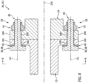
FIG. 8 is a partial sectional illustration of a rotating structure. -
FIG. 9 is a cross-sectional illustration of the rotating structure taken along line 9-9 inFIG. 8 . -
FIG. 10 is a patrial perspective cutaway illustration of the socket device with an adaptor mounted to a socket. -
FIG. 11 is a perspective illustration of the adaptor configured with fingers. -
FIG. 12 is a partial perspective cutaway illustration of the adaptor ofFIG. 11 mated with the fastener assembly during tightening, where the socket is omitted for clarity of illustration. -
FIGS. 13 and14 are end view illustrations of the fastener assembly with various washer configurations. -
FIG. 15 is a partial sectional illustration of the fastener assembly ofFIG. 14 arranged with the socket device for tightening. -
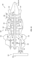
FIG. 16 is a side schematic illustration of a gas turbine engine. -
FIG. 1 illustrates atool 20 for use in securingcomponents structure 26 together at a joint with one or more fastener assemblies 28 (one fastener assembly shown inFIG. 1 ). Thetool 20 ofFIG. 1 includes adriver 30 and asocket device 32. Examples of thedriver 30 include, but are not limited to, a manual rachet, a power rachet (e.g., an electrically or pneumatically powered impact wrench) or any other device capable of driving rotation of thesocket device 32 about anaxis 34, whichaxis 34 may be a centerline axis and/or a rotational axis of thesocket device 32 and/or therespective fastener assembly 28. - The
socket device 32 ofFIG. 1 is configured to operatively couple thedriver 30 to a fastener element 36 of therespective fastener assembly 28. Thedriver 30 may thereby drive rotation of the fastener element 36 about theaxis 34 through thesocket device 32 by driving rotation of thesocket device 32 about theaxis 34. For ease of description, the fastener element 36 ofFIG. 1 may be described herein as a head 38 of afastener 40; e.g., a bolt. However, it is contemplated the fastener element 36 may alternatively be anut 42 threaded onto ashank 44 of thefastener 40 ofFIG. 1 (or another type of fastener such as threaded stud). Thesocket device 32 ofFIG. 1 is also configured to center awasher 46 of therespective fastener assembly 28 with the fastener element 36 (e.g., the bolt head) as the fastener element 36 is rotated about theaxis 34. For ease of description, thewasher 46 may be described herein as a regular washer. However, it is contemplated thewasher 46 may alternatively be a lock washer or any other type of washer which would benefit from centering as described herein. - Referring to
FIG. 2 , thesocket device 32 extends axially along theaxis 34 between and to a first (e.g., tool side) end 48 of thesocket device 32 and a second (e.g., fastener side) end 50 of thesocket device 32. Thesocket device 32 includes asocket 52 and awasher centering sleeve 54. - The
socket 52 may be arranged at the devicefirst end 48. Thesocket 52 ofFIG. 2 , for example, extends axially along theaxis 34 from the devicefirst end 48 to the centeringsleeve 54. Thesocket 52 ofFIG. 2 includes adriver receptacle 56 and afastener receptacle 58. - The
driver receptacle 56 is configured to receive adrive element 60 of thedriver 30. Thedriver receptacle 56 ofFIG. 2 , for example, projects axially into thesocket device 32 and itssocket 52 from the devicefirst end 48 to anaxial end 62 of thedriver receptacle 56. - Referring to
FIG. 3 , thedriver receptacle 56 may be configured with polygonal cross-sectional geometry when viewed, for example, in a reference plane perpendicular to theaxis 34. The cross-sectional geometry of thedriver receptacle 56 may be sized and shaped to match (e.g., be the substantially the same as) a cross-sectional geometry of thedrive element 60. The cross-sectional geometry of thedriver receptacle 56 ofFIG. 3 , for example, is square shaped and sized slightly larger than thedrive element 60 such that thedrive element 60 may be readily mated with (or removed from) thedriver receptacle 56. An example specification for sizing thedriver receptacle 56 and/or thedrive element 60 can be found in the American Society of Mechanical Engineers (ASME) standard B 107.4; however, the present disclosure is not limited to this standard. With this arrangement, one or more flats 64 (e.g., planar surfaces) forming sides of thedriver receptacle 56 may respectively engage (e.g., contact) one or morerespective flats 66 forming sides of thedrive element 60 to rotationally fix thesocket 52 and, more generally, thesocket device 32 to thedrive element 60. Of course, various other coupling techniques are known in the art for rotatably fixing elements together and the present disclosure is not limited to any particular ones thereof. - Referring to
FIG. 2 , thefastener receptacle 58 is configured to receive the fastener element 36 (seeFIG. 1 ). Thefastener receptacle 58 ofFIG. 2 , for example, projects axially into the socket 52 (and axially within the socket device 32) from a second (e.g., fastener side) end 68 of thesocket 52 to anaxial end 70 of thefastener receptacle 58. The socketsecond end 68 ofFIG. 2 is recessed slightly axially in from the devicesecond end 50 such that anopening 72 to thefastener receptacle 58 is proximate the devicesecond end 50. - Referring to
FIG. 4 , thefastener receptacle 58 may be configured with polygonal cross-sectional geometry when viewed, for example, in a reference plane perpendicular to theaxis 34. The cross-sectional geometry of thefastener receptacle 58 may be sized and shaped to match (e.g., be the substantially the same as) or otherwise accommodate a cross-sectional geometry of the fastener element 36. The cross-sectional geometry of thefastener receptacle 58 ofFIG. 4 , for example, is double hex shaped (or triple square shaped) and sized slightly larger than the fastener element 36 such that the fastener element 36 may be readily mated with (or removed from) thefastener receptacle 58. An example specification for sizing the fastener element 36 and/or thefastener receptacle 58 can be found in the ASME standard B107.110; however, the present disclosure is not limited to this standard. With this arrangement, one or more flats 74 (only some of which are labeled for ease of illustration) (e.g., planar surfaces) forming sides of thefastener receptacle 58 may respectively engage (e.g., contact) one or more respective flats 76 (only some of which are labeled for ease of illustration) forming sides of the fastener element 36 to rotationally fix thesocket 52 and, more generally, thesocket device 32 to the fastener element 36; e.g., the bolt head. Here, thefastener element flats 76 form anexterior wrenching feature 78 of the fastener element 36; e.g., a single hex shaped wrenching feature. The present disclosure, however, is not limited to such an exemplary fastener receptacle, fastener element nor wrenching feature configuration. The cross-sectional geometry of thefastener receptacle 58, the fastener element 36 and/or thewrenching feature 78, for example, may alternatively be hexagonal (e.g., single hex) shaped, square shaped, double square shaped, Torx coupling shaped, etc. Furthermore, it is contemplated the wrenchingfeature 78 may alternatively be configured as an internal wrenching feature such as a socket for an Allen head, a Torx head, etc. - Referring to
FIG. 2 , thefastener receptacle 58 has anaxial length 80 measured from thefastener receptacle opening 72 at the socketsecond end 68 to thefastener receptacle end 70. Thisfastener receptacle length 80 may be sized to be equal to or larger than anaxial thickness 82 of the fastener element 36 to be received within thefastener receptacle 58. - The centering
sleeve 54 may be arranged at the devicesecond end 50. The centeringsleeve 54 ofFIG. 2 , for example, extends axially along theaxis 34 from the socketsecond end 68 to the devicesecond end 50. The centeringsleeve 54 extends radially from a (e.g., cylindrical)inner surface 84 of the centeringsleeve 54 to anouter surface 86 of thesocket device 32. Referring toFIG. 5 , the centeringsleeve 54 extends circumferentially about (e.g., completely around) theaxis 34 providing the centeringsleeve 54 with a full-hoop geometry annular geometry. - Referring to
FIG. 2 , the centeringsleeve 54 forms a counterbore 88 in thesocket device 32 at the devicesecond end 50. This counterbore 88 projects axially into thesocket device 32 and its centeringsleeve 54 from the devicesecond end 50 to a (e.g., unsegmented, annular)shoulder 90 at the socketsecond end 68. The counterbore 88 projects radially outward (away from the axis 34) into thesocket device 32 and its centeringsleeve 54 from thefastener receptacle flats 74 to the sleeveinner surface 84. This counterbore 88 may form a receptacle 92 for thewasher 46. In particular, the centeringsleeve 54 is configured to receive thewasher 46 in the washer receptacle 92. The washer receptacle 92 ofFIG. 5 , for example, may be configured with a circular cross-sectional geometry when viewed, for example, in a reference plane perpendicular to theaxis 34. This circular cross-sectional geometry is sized to match (e.g., be substantially the same as) a circular cross-sectional geometry of thewasher 46. A radius of the sleeveinner surface 84, for example, may be sized to be equal to or slightly larger than a radius of a (e.g., cylindrical)outer surface 94 of thewasher 46. An example specification for sizing thewasher 46 and/or the centeringsleeve 54 can be found in the ASME standard Y14.5; however, the present disclosure is not limited to this standard. With such an arrangement, thewasher 46 may be readily mated with (or removed from) the washer receptacle 92. However, the sleeveinner surface 84 may follow the washerouter surface 94 close enough so as to provide an alignment guide for thewasher 46 as described below in further detail. - Referring to
FIG. 2 , the washer receptacle 92 has anaxial length 96 measured from anopening 98 to the washer receptacle 92 at the devicesecond end 50 to thewasher receptacle shoulder 90. Thiswasher receptacle length 96 may be sized to be equal to anaxial thickness 100 of thewasher 46 to be received therein. In other embodiments, it is contemplated thewasher receptacle length 96 may alternatively be slightly smaller than thewasher thickness 100. However, in general, thewasher receptacle length 96 is not larger than thewasher thickness 100 such that, for example, thesocket device 32 does not project axially beyond thewasher 46 and potentially rub against the first component 22 (seeFIG. 1 ). Furthermore, thewasher receptacle length 96 may be sized smaller than thewasher thickness 100 where an outer diameter of thewasher 46 is smaller than a maximum diameter of a bearing surface (e.g., a surface contacting the washer 46) of the fastener head 38 (or the nut 42) to avoid axial pinching of the devicesecond end 50 against thefirst component 22, for example, under an application of torque preloading thewasher 46. Thewasher receptacle length 96 may also be sized smaller than thewasher thickness 100 to avoid rubbing of the devicesecond end 50 against a critical surface finish of mating parts under thewasher 46; e.g., thefirst component 22 ofFIG. 1 . -
FIG. 6 is a flow diagram of amethod 600 for assembling a structure. For ease of description, theassembly method 600 may be described below with respect to thetool 20 and thestructure 26 ofFIGS. 1-5 . Themethod 600 of the present disclosure, however, may alternatively be performed to assemble a structure with various other configurations. Theassembly method 600 may also or alternatively be performed using a tool with various other configurations. Thesocket device 32 ofFIGS. 1-5 , for example, may alternatively be swapped out for any one of the other socket device configurations discussed below. - In
step 602, thefirst component 22 is arranged with thesecond component 24. A mount 102 (e.g., an annular flange or rim) of thefirst component 22 ofFIG. 1 , for example, is arranged axially adjacent and abutted against a mount 104 (e.g., an annular flange or rim) of thesecond component 24. Afirst fastener aperture 106 through thefirst mount 102 is aligned with (e.g., positioned coaxial with) asecond fastener aperture 108 through thesecond mount 104. - In
step 604, thefastener assembly 28 is arranged with thefirst component 22 and thesecond component 24. Thewasher 46 ofFIG. 1 , for example, is mounted onto thefastener 40. In particular, a distalaxial end 110 of thefastener shank 44 is passed through a bore of thewasher 46 to slide thewasher 46 onto thefastener shank 44. Thewasher 46 thereby circumscribes thefastener shank 44, and thewasher 46 may axially engage (e.g., abut against) the fastener head 38. The fastener 40 (with the mounted washer 46) may then by mated with thefastener apertures shank end 110, for example, may be passed sequentially through thefirst fastener aperture 106 and thesecond fastener aperture 108 until, for example, thewasher 46 axially engages (e.g., abuts against) thefirst component 22. Thenut 42 may then be mated with thefastener shank 44. Thenut 42, for example, may be threaded onto thefastener shank 44 until, for example, thenut 42 axially engages (e.g., abuts against) thesecond component 24. Alternatively, thefastener shank 44 may be threaded into thenut 42 as thefastener 40 is mated with thefastener apertures fastener apertures nut 42, themembers axis 34 between the fastener head 38 and thenut 42. - In step 606, the
socket device 32 is mated with the fastener element 36 and thewasher 46. Thesocket device 32 ofFIG. 2 , for example, is slid (e.g., translated) axially onto thefastener assembly 28 such that (A) the fastener head 38 and itswrenching feature 78 are received within thefastener receptacle 58 and (B) thewasher 46 is received within the washer receptacle 92. Within thefastener receptacle 58 ofFIG. 4 , one or more of thefastener receptacle flats 74 may respectively engage (e.g., abut against) one or more of thefastener element flats 76. Within the washer receptacle 92 ofFIG. 2 , thewasher 46 may axially engage (e.g., abut against) thewasher receptacle shoulder 90. Referring toFIG. 5 , at least a portion of the washerouter surface 94 may also or alternatively radially engage (e.g., abut against) at least a portion of the sleeveinner surface 84. By forming a boundary circumferentially around thewasher 46, the centeringsleeve 54 may prevent thewasher 46 from shifting outside of that boundary set by the centeringsleeve 54. The centeringsleeve 54 may thereby maintain thewasher 46 centered with (e.g., coaxial with) the fastener element 36 while thewasher 46 is within the washer receptacle 92. - In
step 608, thefastener assembly 28 is tightened (e.g., torqued to specification) using thesocket device 32. Thedriver 30, for example, rotates thesocket device 32 about theaxis 34. The rotation of thesocket device 32 in turn drives rotation of the fastener head 38 about theaxis 34 while thenut 42 is held circumferentially fixed; e.g., via another tool, a fixture or elsewise. Thefaster shank 44 may thereby be threaded further into thenut 42 until a desired preload is provided. During this tightening, thewasher 46 remains bounded by the centeringsleeve 54. The centeringsleeve 54 may thereby prevent (or at least significantly limit within tolerances) any skewing (e.g., misalignment, eccentricity) between thewasher 46 and the fastener element 36. By contrast, referring toFIG. 7 , awasher 700 may skew to a side of a fastener head 702 (e.g., thewasher 700 and thehead 702 may become eccentric) during a tightening process where thewasher 700 is unbounded, as is the case when using a traditional socket to rotate thefastener head 702 for example. Skewing between thewasher 700 and thefastener head 702 may have a negative impact on pressure loading / distribution onto anadjacent component 704. Furthermore, skewing between thewasher 700 and thefastener head 702 may induce a rotational imbalance where theelements rotating structure 706. - Referring to
FIG. 1 , once thefastener assembly 28 is tightened (e.g., torqued to specification) using thesocket device 32, thatfastener assembly 28 secures (e.g., fixes) thefirst component 22 to thesecond component 24. Thesteps first component 22 to thesecond component 24 using more or moreadditional fastener assemblies 28 as shown, for example, inFIGS. 8 and9 . In the embodiment ofFIGS. 8 and9 , thestructure 26 is configured as a rotating structure 112. This rotating structure 112 is configured to rotate about arotational axis 114 of the rotating structure 112, where thefastener assemblies 28 are arranged circumferentially about therotational axis 114 in an array. In such embodiments, one of the components (e.g., the first component 22) may be configured as or otherwise include a torque transfer device (e.g., a shaft or other linkage), and the other one of the components (e.g., the second component 24) may be configured as or otherwise includes a rotor (e.g., a bladed compressor rotor, a bladed turbine rotor, etc.). Of course, in other embodiments, eachcomponent components - In some embodiments, referring to
FIG. 2 , thesocket device 32 may be configured as a monolithic body. Thesocket 52 and the centeringsleeve 54, for example, may be forged, machined, additively manufactured and/or otherwise formed from a single mass of material. - In some embodiments, referring to
FIG. 10 , the centeringsleeve 54 may be formed discrete from thesocket 52 and subsequently attached to thesocket 52. The centeringsleeve 54 ofFIGS. 10 and 11 , for example, is formed as part of asocket adaptor 116. Thissocket adaptor 116 includes the centeringsleeve 54 and asleeve mount 118 connected to (e.g., formed integral with) the centeringsleeve 54. Thesleeve mount 118 may be configured as a tubular body which projects axially out from the centeringsleeve 54. Thissleeve mount 118 is mounted onto thesocket 52, where thesleeve mount 118 axially overlaps and circumscribes thesocket 52. Thesleeve mount 118 may be attached to thesocket 52 via bonding (e.g., brazing, welding, adhering, etc.) and/or via a mechanical connection (e.g., an interference fit, a press fit, etc.). With this arrangement, thesleeve mount 118 mounts the centeringsleeve 54 to thesocket 52 at the socketsecond end 68. - In some embodiments, referring to
FIGS. 5 and10 , the sleeveinner surface 84 may be configured as a circumferentially uninterrupted cylindrical surface. With this arrangement, the centeringsleeve 54 may have a full-hoop annular geometry. - In some embodiments, referring to
FIG. 11 , the sleeveinner surface 84 may be one of a plurality of sleeveinner surfaces 84 formed / carried by the centeringsleeve 54. Thesocket adaptor 116 ofFIG. 11 , for example, includes a plurality offingers 120. Each circumferentially neighboring (e.g., adjacent) pair of thefingers 120 is separated by aslot 122. Eachslot 122 extends radially through thesocket adaptor 116. Eachslot 122 extends circumferentially within thesocket adaptor 116 between therespective fingers 120. Eachslot 122 projects radially into thesocket adaptor 116 from the devicesecond end 50, through the centeringsleeve 54, and partially into thesleeve mount 118. With this arrangement, eachfinger 120 may include a respectivecircumferential segment 124 of the centeringsleeve 54 and its respective sleeveinner surface 84. - Referring to
FIG. 12 , each centeringsleeve segment 124 and its respective sleeveinner surface 84 may be configured to radially engage (e.g., abut against) the washerouter surface 94. Furthermore, each centeringsleeve segment 124 may (or may not) be biased slightly against the washerouter surface 94. The radius of each sleeveinner surface 84, for example, may be sized slightly smaller than the radius of the washerouter surface 94. With such an arrangement, the centeringsleeve 54 and thefingers 120 may splay slightly open to mate with and clamp onto thewasher 46. - Where the centering
sleeve 54 includes multiple sleeveinner surfaces 84, each sleeveinner surface 84 may be arcuate (e.g., a circular segment). Furthermore, each sleeveinner surface 84 may have a uniform (e.g., constant) radius to theaxis 34 as that sleeveinner surface 84 extends circumferentially about theaxis 34 between opposing circumferential sides of therespective finger 120 and its centeringsleeve segment 124. - In some embodiments, referring to
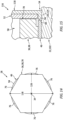
FIG. 13 , anouter diameter 126 of the washerouter surface 94 may be sized greater than (or equal to) a largestouter lateral width 128 of the fastener element 36 and/or itswrenching feature 78. In other embodiments, referring toFIG. 14 , theouter diameter 126 of the washerouter surface 94 may be sized smaller than the largestouter lateral width 128 of the fastener element 36 and/or itswrenching feature 78. In such embodiments, referring toFIG. 15 , the centeringsleeve 54 and at least one or more or all of itscircumferential segments 124 may be positioned axially between the fastener element 36 and thefirst component 22. The ability for thefingers 120 to splay apart therefore may facilitate mating the centeringsleeve 54 with thewasher 46 / removal of the centeringsleeve 54 from thewasher 46. -
FIG. 16 illustrates agas turbine engine 130 which may include thestructure 26 ofFIG. 1 / the rotating structure 112 ofFIGS. 8 and9 . Thisgas turbine engine 130 includes amechanical load 132 and a gasturbine engine core 134. - The
mechanical load 132 may be configured as or otherwise include at least (or only) one drivenrotor 136. This drivenrotor 136 may be a bladed propulsor rotor for an aircraft propulsion system. The drivenrotor 136, for example, may be a propeller rotor where thegas turbine engine 130 is configured as a turboprop gas turbine engine. The drivenrotor 136 may alternatively be a helicopter rotor (e.g., a main rotor) where thegas turbine engine 130 is configured as a turboshaft gas turbine engine. The present disclosure, however, is not limited to turboprop and turboshaft gas turbine engine applications. Thegas turbine engine 130, for example, may alternatively be configured as a turbofan gas turbine engine and the bladed rotor may be a fan rotor. In another example, thegas turbine engine 130 may be configured as a turbojet gas turbine engine and the bladed rotor may be a compressor rotor. Furthermore, the present disclosure is not limited to aircraft propulsion system applications. The drivenrotor 136, for example, may alternatively be a generator rotor where thegas turbine engine 130 is included in a power generation system for an aircraft or non-aircraft application; e.g., an auxiliary power unit (APU) or an industrial powerplant. - The
engine core 134 ofFIG. 16 extends axially along an axial centerline 138 of theengine core 134. This axial centerline 138 may be coaxial with a rotational axis 140 (e.g., the rotational axis 114) of one or more rotors included in theengine core 134. The axial centerline 138 may also be parallel with arotational axis 142 of the drivenrotor 136. Theengine core 134 ofFIG. 16 includes acompressor section 144, acombustor section 145 and aturbine section 146. Theturbine section 146 includes a high pressure turbine (HPT)section 146A and a low pressure turbine (LPT)section 146B. - The engine sections 144-146B are arranged sequentially along a (e.g., annular)
core flowpath 148 and within anengine housing 150. This core flowpath 148 extends longitudinally within theengine core 134 from anupstream airflow inlet 152 into theengine core 134 to adownstream airflow exhaust 154 from theengine core 134. Here, theairflow inlet 152 is also an inlet into thegas turbine engine 130 and theexhaust 154 is also an exhaust from thegas turbine engine 130; however, the present disclosure is not limited to such an exemplary arrangement. Theengine housing 150 ofFIG. 16 includes an engine case (e.g., a core case) housing thecompressor section 144, thecombustor section 145 and theturbine section 146. - The
compressor section 144, theHPT section 146A and theLPT section 146B each include one or more bladed rotors 156-158. Each of these bladed rotors 156-158 includes a plurality of rotor blades arranged circumferentially around and connected to one or more respective rotor disks. The rotor blades, for example, may be formed integral with or mechanically fastened, welded, brazed, adhered and/or otherwise attached to the respective rotor disk(s). - The
compressor rotor 156 is connected to and driven by theHPT rotor 157 through ahigh speed shaft 160. At least (or only) thecompressor rotor 156, theHPT rotor 157 and thehigh speed shaft 160 may collectively form a highspeed rotating structure 162 that is rotatable about the rotational axis 140. The drivenrotor 136 ofFIG. 16 is connected to an output of ageartrain 164. An input of thegeartrain 164 is connected to theLPT rotor 158 through alow speed shaft 166. At least (or only) theLPT rotor 158 and thelow speed shaft 166 may collectively form a lowspeed rotating structure 168 that is rotatable about the rotational axis 140. Each of theengine shafts FIG. 16 for ease of illustration). Each of these bearings is connected to theengine housing 150 by an internal engine support structure. Here, the rotating structure 112 ofFIGS. 8 and9 may be configured as part of one of therotating structures - During gas turbine engine operation, air enters the
engine core 134 through theairflow inlet 152 and enters thecore flowpath 148. The air within thecore flowpath 148 may be referred to as "core air". This core air is compressed by thecompressor rotor 156 and directed into a (e.g., annular)combustion chamber 170 of a (e.g., annular) combustor in thecombustor section 145. Fuel is injected into thecombustion chamber 170 through one or more fuel injectors and mixed with the compressed core air to provide a fuel-air mixture. This fuel-air mixture is ignited and combustion products thereof flow through and sequentially cause theHPT rotor 157 and theLPT rotor 158 to rotate. The rotation of theHPT rotor 157 drives rotation of thecompressor rotor 156 and, thus, compression of the air received from theairflow inlet 152. The rotation of theLPT rotor 158 drives rotation of the drivenrotor 136. - While various embodiments of the present disclosure have been described, it will be apparent to those of ordinary skill in the art that many more embodiments and implementations are possible within the scope of the disclosure. For example, the present disclosure as described herein includes several aspects and embodiments that include particular features. Although these features may be described individually, it is within the scope of the present disclosure that some or all of these features may be combined with any one of the aspects and remain within the scope of the disclosure. Accordingly, the present disclosure is not to be restricted except in light of the attached claims and their equivalents.
Claims (15)
- An assembly method, comprising:arranging a first component (22) with a second component (24); andsecuring the first component (22) to the second component (24) using a fastener assembly (28), the fastener assembly (28) including a fastener element (36) and a washer (46), the fastener element (36) comprising a wrenching feature (78), the washer (46) having a full-hoop annular body with a cylindrical outer surface (94), and the securing including:mating a socket device (32) with the fastener element (36) and the washer (46), the socket device (32) engaging the wrenching feature (78) and the cylindrical outer surface (94); androtating the fastener element (36) about an axis (34) using the socket device (32) to tighten the fastener assembly (28) and clamp the washer (46) axially between the first component (22) and the fastener element (36), wherein the socket device (32) centers the washer (46) to the fastener element (36) during the rotating.
- The assembly method of claim 1, wherein:the socket device (32) comprises a cylindrical inner surface (84); andthe cylindrical inner surface (84) circumscribes and is radially adjacent the cylindrical outer surface (94).
- The assembly method of claim 1, wherein:the socket device (32) comprises a plurality of arcuate surfaces (84); andthe plurality of arcuate surfaces (84) are arranged circumferentially around and are radially adjacent the cylindrical outer surface (94).
- The assembly method of claim 1, 2 or 3, wherein:the socket device (32) comprises a counterbore (88) at an axial end (50) of the socket device (32); andthe washer (46) is seated in the counterbore (88).
- The assembly method of claim 4, wherein:the socket device (32) further comprises a receptacle (92) with a polygonal cross-sectional geometry;the receptacle (92) projects axially into the socket device (32) from the counterbore (88); andthe receptacle (92) receives the wrenching feature (78).
- The assembly method of any preceding claim, wherein:the socket device (32) comprises a centering sleeve (54); andthe centering sleeve (54) extends circumferentially around the washer (46) and radially engages the cylindrical outer surface (94), wherein, optionally, the centering sleeve (54) is circumferentially segmented or the centering sleeve (54) has a full-hoop annular geometry.
- The assembly method of claim 6, wherein:the socket device (32) further comprises a socket (52) that mates with the wrenching feature (78); andthe socket device (32) is configured as a monolithic body.
- The assembly method of claim 6, wherein:the socket device (32) further comprises a socket (52) and a sleeve mount (118);the socket (52) mates with the wrenching feature (78); andthe sleeve mount (118) circumscribes the socket (52), and the sleeve mount (118) mounts the centering sleeve (54) to the socket (52).
- The assembly method of any preceding claim, wherein:an outer diameter (126) of the cylindrical outer surface (94) is equal to or greater than a largest outer lateral width (128) of the fastener element (36); oran outer diameter (126) of the cylindrical outer surface (94) is less than a largest outer lateral width (128) of the fastener element (36).
- The assembly method of any preceding claim, wherein:the fastener element (36) comprises a bolt head (38); and/ora gas turbine engine rotating structure (26, 112) comprises the first component (22), the second component (24) and the fastener assembly (28).
- The assembly method of any preceding claim, wherein:the first component (22) comprises a first mount (102);the second component (24) comprises a second mount (104) abutted against the first mount (102); andthe fastener assembly (28) secures the first mount (102) to the second mount (104).
- An assembly method, comprising:arranging a first component (22) with a second component (24); andsecuring the first component (22) to the second component (24) using a fastener assembly (28), the fastener assembly (28) including a bolt (40) and a washer (46), the bolt (40) comprising a bolt head (38) with a wrenching feature (78), the washer (46) having an outer surface (94), and the securing including:mating a socket device (32) with the bolt head (38) and the washer (46), the socket device (32) engaging the wrenching feature (78) and the outer surface (94); androtating the bolt head (38) about an axis (34) using the socket device (32) to tighten the fastener assembly (28) and clamp the washer (46) axially between the first component (22) and the bolt head (38), wherein the socket device (32) maintains the washer (46) coaxial with the bolt (40) during the rotating, wherein, optionally, the outer surface (94) is a cylindrical outer surface of the washer (46).
- A socket device (32), comprising:a socket (52) including an axial end (50) and a receptacle (92) with a polygonal cross-sectional geometry, the receptacle (92) projecting axially along an axis (34) into the socket (52) from the axial end (50), and the socket (52) configured to receive a fastener element (36) within the receptacle (92), wherein the fastener element (36) is a bolt head (38) or a nut (42); anda socket adaptor (116) including a centering sleeve (54) and a sleeve mount (118);the centering sleeve (54) comprising an inner surface (84) and forming a counterbore (88) at the axial end (50) of the socket (52), the centering sleeve (54) configured to receive a washer (46) within the counterbore (88), the centering sleeve (54) projecting radially inward to the inner surface (84), the inner surface (84) configured to radially engage the washer (46), and the inner surface (84) having a uniform radius to the axis (34) as the inner surface (84) extends circumferentially about the axis (34); andthe sleeve mount (118) circumscribing the socket (52) and mounting the centering sleeve (54) to the socket (52).
- The socket device (32) of claim 13, wherein:the centering sleeve (54) has a full-hoop annular geometry; andthe inner surface (84) is a cylindrical inner surface.
- The socket device (32) of claim 13 or 14, wherein:the socket adaptor (116) further includes a plurality of fingers (120) arranged circumferentially about the axis (34); andeach of the plurality of fingers (120) includes a respective circumferential section of the centering sleeve (54).
Applications Claiming Priority (1)
| Application Number | Priority Date | Filing Date | Title |
|---|---|---|---|
| US17/983,815 US12115623B2 (en) | 2022-11-09 | 2022-11-09 | Centering a washer to a fastener element during installation |
Publications (1)
| Publication Number | Publication Date |
|---|---|
| EP4368344A1 true EP4368344A1 (en) | 2024-05-15 |
Family
ID=88779570
Family Applications (1)
| Application Number | Title | Priority Date | Filing Date |
|---|---|---|---|
| EP23208847.6A Pending EP4368344A1 (en) | 2022-11-09 | 2023-11-09 | Centering a washer to a fastener element during installation |
Country Status (3)
| Country | Link |
|---|---|
| US (1) | US12115623B2 (en) |
| EP (1) | EP4368344A1 (en) |
| CA (1) | CA3218765A1 (en) |
Citations (4)
| Publication number | Priority date | Publication date | Assignee | Title |
|---|---|---|---|---|
| US2202240A (en) * | 1937-12-20 | 1940-05-28 | Walter F Trotter | Wrench socket |
| US20160243685A1 (en) * | 2013-09-16 | 2016-08-25 | Dewayne Eugene Blake | Fastener staging and placement system and method of using the same |
| US20170021478A1 (en) * | 2013-12-17 | 2017-01-26 | HYTORC Division Unex Corporation | Apparatus for tightening threaded fasteners |
| US20170067501A1 (en) * | 2015-09-08 | 2017-03-09 | Enduralock, LLC. | Locking mechanisms with deflectable washer members |
Family Cites Families (18)
| Publication number | Priority date | Publication date | Assignee | Title |
|---|---|---|---|---|
| US6152243A (en) * | 1999-08-05 | 2000-11-28 | Junkers; John K. | Universal torque power tool |
| US6389813B2 (en) * | 2000-03-31 | 2002-05-21 | Quiet Systems International, Llc | Passive mounted lining system |
| US6701808B2 (en) | 2002-02-08 | 2004-03-09 | Chih-Ching Hsieh | Wrench capable of preventing a screwed member from slipping out and holding the screwed member |
| US7044031B1 (en) | 2005-05-24 | 2006-05-16 | Steven Mullen | Fastener driving tool |
| US8069754B2 (en) | 2008-06-13 | 2011-12-06 | Kenneth Lee Elgin | Socket wrench with washer gripping arms |
| US8079795B2 (en) * | 2009-03-23 | 2011-12-20 | Junkers John K | Washer for tightening and loosening threaded connectors |
| US20110185860A1 (en) | 2010-02-02 | 2011-08-04 | Maan-Jyi Chang | Socket Assembly |
| JP5787350B2 (en) | 2010-04-27 | 2015-09-30 | ユニタイト株式会社 | Fastening structure, reaction force washer used therefor, and fastening socket |
| US9206705B2 (en) * | 2012-03-07 | 2015-12-08 | Mitsubishi Hitachi Power Systems, Ltd. | Sealing device and gas turbine having the same |
| TW201350275A (en) | 2012-06-05 | 2013-12-16 | li-yuan Song | Strengthened sleeve |
| TW201417961A (en) | 2012-11-05 | 2014-05-16 | li-yuan Song | Sleeve with enhanced strength |
| US20190003512A1 (en) * | 2013-02-05 | 2019-01-03 | HYTORC Division Unex Corporation | Apparatus for tightening threaded fasteners |
| US9416810B2 (en) | 2014-07-11 | 2016-08-16 | Rtodds Engineering, Llc | Elastomeric retaining devices for joining elements |
| CN206154188U (en) | 2016-09-26 | 2017-05-10 | 上海拓岚机械科技有限公司 | Omnipotent socket ratchet wrench |
| US10751858B1 (en) | 2016-12-15 | 2020-08-25 | Lockhead Martin Corporation | Hardware installation aid |
| FR3085943A1 (en) * | 2018-09-19 | 2020-03-20 | Airbus Operations | METHOD FOR ASSEMBLING AN AIRCRAFT MAT |
| US11045930B2 (en) | 2018-11-28 | 2021-06-29 | GM Global Technology Operations LLC | Non-ferrous fastener retention socket |
| IT202000006460A1 (en) | 2020-03-27 | 2021-09-27 | Polykap S R L | SCREWDRIVER FOR THREADED CAP AND CLAMPING DEVICE |
-
2022
- 2022-11-09 US US17/983,815 patent/US12115623B2/en active Active
-
2023
- 2023-11-03 CA CA3218765A patent/CA3218765A1/en active Pending
- 2023-11-09 EP EP23208847.6A patent/EP4368344A1/en active Pending
Patent Citations (4)
| Publication number | Priority date | Publication date | Assignee | Title |
|---|---|---|---|---|
| US2202240A (en) * | 1937-12-20 | 1940-05-28 | Walter F Trotter | Wrench socket |
| US20160243685A1 (en) * | 2013-09-16 | 2016-08-25 | Dewayne Eugene Blake | Fastener staging and placement system and method of using the same |
| US20170021478A1 (en) * | 2013-12-17 | 2017-01-26 | HYTORC Division Unex Corporation | Apparatus for tightening threaded fasteners |
| US20170067501A1 (en) * | 2015-09-08 | 2017-03-09 | Enduralock, LLC. | Locking mechanisms with deflectable washer members |
Also Published As
| Publication number | Publication date |
|---|---|
| CA3218765A1 (en) | 2024-05-09 |
| US20240149404A1 (en) | 2024-05-09 |
| US12115623B2 (en) | 2024-10-15 |
Similar Documents
| Publication | Publication Date | Title |
|---|---|---|
| US7195447B2 (en) | Gas turbine engine and method of assembling same | |
| US8215902B2 (en) | Scalable high pressure compressor variable vane actuation arm | |
| CN105308265B (en) | Including be arranged on be shell between axis and rotor combustion gas turbine system shaft device | |
| US11629596B1 (en) | Rotor assembly for a gas turbine engine and method for assembling same | |
| EP3657032B1 (en) | Mount assembly with bolt head lock plate(s) | |
| EP3222857B1 (en) | Mechanical joint with a flanged retainer | |
| US12055058B2 (en) | Joint between gas turbine engine components with a spring element | |
| US12115623B2 (en) | Centering a washer to a fastener element during installation | |
| EP4279712A2 (en) | Aperture pattern for gas turbine engine component with integral alignment feature | |
| US20230122524A1 (en) | Double splined coupling for a turbine engine | |
| US20230383667A1 (en) | Joint between gas turbine engine components with bonded fastener(s) | |
| US20240392694A1 (en) | Turbine engine phonic wheel with integrated lubricant scoop | |
| US11519271B2 (en) | Turbine engine rotor with flexibly coupled tie bolt | |
| US12515807B2 (en) | Bolted connection between mounting bracket and aircraft engine case(s) | |
| US20260098485A1 (en) | Powerplant jacking insert with exterior and interior threads | |
| US12215630B2 (en) | Flex coupler for hybrid gas turbine engine powerplant | |
| US11788413B2 (en) | Gas turbine engine shaft with lobed support structure | |
| EP4636312A1 (en) | Attaching powerplant structures together using fuel injector bolts | |
| US12601262B1 (en) | Gas turbine engines, methods of securing rotating components therein with threaded nuts, and the threaded nuts | |
| US12540550B2 (en) | Tie shaft for engine rotating assembly | |
| CA3288361A1 (en) | Powerplant jacking insert with exterior and interior threads | |
| CA3262409A1 (en) | Bolted connection between mounting bracket and aircraft engine case(s) |
Legal Events
| Date | Code | Title | Description |
|---|---|---|---|
| PUAI | Public reference made under article 153(3) epc to a published international application that has entered the european phase |
Free format text: ORIGINAL CODE: 0009012 |
|
| STAA | Information on the status of an ep patent application or granted ep patent |
Free format text: STATUS: THE APPLICATION HAS BEEN PUBLISHED |
|
| AK | Designated contracting states |
Kind code of ref document: A1 Designated state(s): AL AT BE BG CH CY CZ DE DK EE ES FI FR GB GR HR HU IE IS IT LI LT LU LV MC ME MK MT NL NO PL PT RO RS SE SI SK SM TR |
|
| STAA | Information on the status of an ep patent application or granted ep patent |
Free format text: STATUS: REQUEST FOR EXAMINATION WAS MADE |
|
| 17P | Request for examination filed |
Effective date: 20241115 |
|
| RBV | Designated contracting states (corrected) |
Designated state(s): AL AT BE BG CH CY CZ DE DK EE ES FI FR GB GR HR HU IE IS IT LI LT LU LV MC ME MK MT NL NO PL PT RO RS SE SI SK SM TR |