EP4368326A1 - Thread repair tool - Google Patents
Thread repair tool Download PDFInfo
- Publication number
- EP4368326A1 EP4368326A1 EP23209533.1A EP23209533A EP4368326A1 EP 4368326 A1 EP4368326 A1 EP 4368326A1 EP 23209533 A EP23209533 A EP 23209533A EP 4368326 A1 EP4368326 A1 EP 4368326A1
- Authority
- EP
- European Patent Office
- Prior art keywords
- corner portions
- shaft
- pair
- threads
- repair tool
- Prior art date
- Legal status (The legal status is an assumption and is not a legal conclusion. Google has not performed a legal analysis and makes no representation as to the accuracy of the status listed.)
- Pending
Links
Images


Classifications
-
- B—PERFORMING OPERATIONS; TRANSPORTING
- B23—MACHINE TOOLS; METAL-WORKING NOT OTHERWISE PROVIDED FOR
- B23G—THREAD CUTTING; WORKING OF SCREWS, BOLT HEADS, OR NUTS, IN CONJUNCTION THEREWITH
- B23G9/00—Working screws, bolt heads, or nuts in conjunction with thread cutting, e.g. slotting screw heads or shanks, removing burrs from screw heads or shanks; Finishing, e.g. polishing, any screw-thread
- B23G9/009—Thread cleaning or repairing
-
- B—PERFORMING OPERATIONS; TRANSPORTING
- B23—MACHINE TOOLS; METAL-WORKING NOT OTHERWISE PROVIDED FOR
- B23G—THREAD CUTTING; WORKING OF SCREWS, BOLT HEADS, OR NUTS, IN CONJUNCTION THEREWITH
- B23G5/00—Thread-cutting tools; Die-heads
- B23G5/02—Thread-cutting tools; Die-heads without means for adjustment
-
- B—PERFORMING OPERATIONS; TRANSPORTING
- B23—MACHINE TOOLS; METAL-WORKING NOT OTHERWISE PROVIDED FOR
- B23G—THREAD CUTTING; WORKING OF SCREWS, BOLT HEADS, OR NUTS, IN CONJUNCTION THEREWITH
- B23G5/00—Thread-cutting tools; Die-heads
- B23G5/02—Thread-cutting tools; Die-heads without means for adjustment
- B23G5/06—Taps
- B23G5/062—Taps with a guiding means part
-
- B—PERFORMING OPERATIONS; TRANSPORTING
- B23—MACHINE TOOLS; METAL-WORKING NOT OTHERWISE PROVIDED FOR
- B23G—THREAD CUTTING; WORKING OF SCREWS, BOLT HEADS, OR NUTS, IN CONJUNCTION THEREWITH
- B23G2200/00—Details of threading tools
- B23G2200/16—Tools with cutting edges spaced unequally around the circumference
-
- B—PERFORMING OPERATIONS; TRANSPORTING
- B23—MACHINE TOOLS; METAL-WORKING NOT OTHERWISE PROVIDED FOR
- B23G—THREAD CUTTING; WORKING OF SCREWS, BOLT HEADS, OR NUTS, IN CONJUNCTION THEREWITH
- B23G2200/00—Details of threading tools
- B23G2200/36—Tools having provision to produce threads of more than one type or size
Definitions
- This disclosure relates to a thread repair tool, and more particularly to a thread repair tool that can be inserted into below a damaged area so that the threads can be repaired.
- Blind threaded holes are commonly formed in metal, plastic or other materials by drilling a hole, and then thereafter cutting threads in the hole with a tap.
- a blind threaded hole is a hole that does not extend entirely through the material.
- a threaded bolt, threaded rod, or the like, with threads matching the hole threads is screwed into the hole. Over time, the blind hole threads may be damaged. Often, the thread damage is restricted to the surface end of the hole, while the threads further in the hole remain undamaged.
- a thread repair tool for rethreading a blind tapped hole having damaged threads above undamaged threads of the hole, including: a shaft having a plurality of curved surfaces that extend from a top end of the shaft to a bottom end of the shaft, the plurality of curved surfaces being concave with respect to an exterior perimeter of the shaft; and wherein the shaft has a plurality of corner portions, each one of the plurality of corner portions being located in between two of the plurality of curved surfaces, a first pair of the plurality of corner portions extending from the top end to the bottom end, and a second pair of the plurality of corner portions having a threaded area proximate to the bottom end, the first pair of the plurality of corner portions being adjacent to each other and the second pair of the plurality of corner portions being adjacent to each other.
- a gage pin is configured to be received by at least one of the plurality of curved surfaces.
- the second pair of the plurality of corner portions has an unthreaded smooth surface that extends from the top end to the threaded area.
- the shaft has four corner portions.
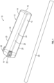
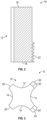
- FIGS. 1-3 illustrate a thread repair tool 10 in accordance with this disclosure.
- the thread repair tool 10 comprises a shaft 12 having a plurality of curved surfaces 14 (one for each side of the shaft 12) that extend from a top end 16 to a bottom end 18. Disposed on opposite sides of each of the curved surfaces is a corner portion 20 each also extending from the top end 16 to the bottom end 18.
- the plurality of curved surfaces 14 are concave in shape with respect to an exterior perimeter of the shaft 12. In other words, each curved surface 14 curves inwardly from the respective corner portion 20. In the illustrated embodiment, there are four corner portions 20. Of course, the number of corner portions 20 may vary. Alternatively, the plurality of curved surfaces 14 may be formed as depressions (e.g., curved or not) as long as they are depressed with respect to the corner portions.
- two adjacent corner portions 20 Proximate to the bottom end 18 of the shaft 12 two adjacent corner portions 20 have a threaded area 22 while the other two adjacent corner portions are unthreaded.
- the threaded area 22 is located proximate to the bottom end.
- the other two corner portions 20 have an unthreaded or smooth surface 24 that extends from the top end 16 to the threaded area 22.
- the two adjacent corner portions 20 with the threaded areas 22 are curved or comprise an arcuate surface so that the threads of the threaded areas 22 can engage the undamaged threads of the blind tapped hole in order repair the damaged threads of the blind tapped hole.
- the gage pin 26 will have a circular or curved exterior in order to facilitate its movement along an interior surface of the tapped hole to be rethreaded.
- the gage pin 26 may have a partially curved surface and another surface (e.g., no curved that is configured to engage a curved or non-curved surface 14 that is formed as a depression (e.g., curved or not) that is depressed with respect to the corner portions (e.g., the alternative embodiment mentioned above).
- FIGS. 4-11 repair of a blind threaded hole 28 using the thread repair tool 10 in accordance with this disclosure is illustrated.
- FIG. 4 a cross-sectional view of a blind threaded hole 28 is illustrated.
- the top portion of the blind threaded hold may have a chamfer 30.
- no chamfer 30 may be provided.
- FIG. 5 shows the damaged area 32 being repaired with a weld 36 wherein the threads 34 of the upper portion 32 are covered by the weld 36 and need to be rethreaded.
- the threads 34 located below the weld cannot be threaded with a traditional tap as its diameter will be larger than the opening of the hole 28.
- the shaft 12 of the thread repair tool 10 can be used for rethreading of the hole 28 as the shaft 12 can have an exterior perimeter that is smaller than the inner diameter of the hole 28 including the weld repair area 36. This allows the shaft 12 to be inserted past the weld 36 in the direction of arrow 38. See at least FIG. 7 . This also allows the threaded areas 22 of the shaft 12 to pass the weld 36 and thereafter, the shaft 12 can move horizontally in the direction of arrow 40 so that the threaded areas 22 of the shaft 12 can engage the undamaged threads 34 located below the weld area 36 in order to thread the weld 36. This is illustrated in at least FIG. 8 .
- the gage pin is inserted between the weld area 36 and one of the curved surfaces 14 of the shaft 12. This will maintain the threaded areas 22 in contact with the undamaged threads 34.
- The is illustrated in at least FIG. 9 .
- the shaft 12 is rotated counter clockwise in the direction of arrow 42 by for example, a tool (e.g., wrench, socket or other equivalent item) configured to engage the top end 16 of the shaft 12 such that once the tool has engaged the top end 16 of the shaft and is rotated the shaft 12 will rotate.
- a tool e.g., wrench, socket or other equivalent item
- the shaft is rotated upwardly in a direction opposite to arrow 38 until the weld 36 is now threaded. This is illustrated in at least FIG. 11 . While a counter clockwise rotation is illustrated in FIG. 10 . It is contemplated that a clockwise rotation may be employed depending on the pitch (e.g., number of threads per inch), type (e.g., standard, metric, ACME, NPT, etc.), and direction (e.g., left or right handed) of the threads 34 to be repaired.
- pitch e.g., number of threads per inch
- type e.g., standard, metric, ACME, NPT, etc.
- direction e.g., left or right handed
- a new thread repair tool 10 wherein the tool 10 is able to be offset and bypass the top repaired minor diameter (that has no thread) and reengage the remaining threads at the bottom of the hole picking up the pitch that otherwise would not have been known. It being understood that a minimal amount of threads are needed for engagement by the thread repair tool 10 or that the thread repair tool 10 can reach the bottom of the hole 28. After engagement, rolls are used to secure the cutting edge to its proper pitch diameter, and it then cuts the new threads from the bottom out reverse direction.
Landscapes
- Engineering & Computer Science (AREA)
- Mechanical Engineering (AREA)
- Reinforcement Elements For Buildings (AREA)
- Hand Tools For Fitting Together And Separating, Or Other Hand Tools (AREA)
Abstract
Description
- This disclosure relates to a thread repair tool, and more particularly to a thread repair tool that can be inserted into below a damaged area so that the threads can be repaired.
- Blind threaded holes are commonly formed in metal, plastic or other materials by drilling a hole, and then thereafter cutting threads in the hole with a tap. A blind threaded hole is a hole that does not extend entirely through the material. In use, a threaded bolt, threaded rod, or the like, with threads matching the hole threads is screwed into the hole. Over time, the blind hole threads may be damaged. Often, the thread damage is restricted to the surface end of the hole, while the threads further in the hole remain undamaged.
- Accordingly, it is desirable to provide a tool for repairing or rethreading threads in a blind hole.
- According to a first aspect of the invention, there is a thread repair tool for rethreading a blind tapped hole having damaged threads above undamaged threads of the hole, including: a shaft having a plurality of curved surfaces that extend from a top end of the shaft to a bottom end of the shaft, the plurality of curved surfaces being concave with respect to an exterior perimeter of the shaft; and wherein the shaft has a plurality of corner portions, each one of the plurality of corner portions being located in between two of the plurality of curved surfaces, a first pair of the plurality of corner portions extending from the top end to the bottom end, and a second pair of the plurality of corner portions having a threaded area proximate to the bottom end, the first pair of the plurality of corner portions being adjacent to each other and the second pair of the plurality of corner portions being adjacent to each other.
- In an embodiment of the above, a gage pin is configured to be received by at least one of the plurality of curved surfaces.
- In an embodiment of any of the above, the second pair of the plurality of corner portions has an unthreaded smooth surface that extends from the top end to the threaded area.
- In an embodiment of any of the above, the shaft has four corner portions.
- The following descriptions should not be considered limiting in any way. With reference to the accompanying drawings, like elements are numbered alike:
-
FIG. 1 is a perspective view of a thread repair tool in accordance with this disclosure; -
FIG. 2 is a cross-sectional view of a thread repair tool in accordance with this disclosure; -
FIG. 3 is a top view of a thread repair tool in accordance with this disclosure; and -
FIGS. 4-11 illustrate repair of a blind threaded hole with a thread repair tool in accordance with this disclosure. - A detailed description of one or more embodiments of the disclosed apparatus and method are presented herein by way of exemplification and not limitation with reference to the FIGS.
- As reference herein, the terms horizontal, upright, vertical, above, below, beneath, and the like, are used solely for the purpose of clarity in illustrating the present disclosure with reference to the figures and should not be taken as words of limitation.
-
FIGS. 1-3 illustrate athread repair tool 10 in accordance with this disclosure. Thethread repair tool 10 comprises ashaft 12 having a plurality of curved surfaces 14 (one for each side of the shaft 12) that extend from atop end 16 to abottom end 18. Disposed on opposite sides of each of the curved surfaces is acorner portion 20 each also extending from thetop end 16 to thebottom end 18. The plurality ofcurved surfaces 14 are concave in shape with respect to an exterior perimeter of theshaft 12. In other words, eachcurved surface 14 curves inwardly from therespective corner portion 20. In the illustrated embodiment, there are fourcorner portions 20. Of course, the number ofcorner portions 20 may vary. Alternatively, the plurality ofcurved surfaces 14 may be formed as depressions (e.g., curved or not) as long as they are depressed with respect to the corner portions. - Proximate to the
bottom end 18 of theshaft 12 twoadjacent corner portions 20 have a threadedarea 22 while the other two adjacent corner portions are unthreaded. The threadedarea 22 is located proximate to the bottom end. As such, the other twocorner portions 20 have an unthreaded orsmooth surface 24 that extends from thetop end 16 to the threadedarea 22. The twoadjacent corner portions 20 with the threadedareas 22 are curved or comprise an arcuate surface so that the threads of the threadedareas 22 can engage the undamaged threads of the blind tapped hole in order repair the damaged threads of the blind tapped hole. - In contrast to the
smooth surfaces 24, all of thecurved surfaces 14 extend all the way from thetop end 16 to thebottom end 18. This allows thethread repair tool 10 to be used with agage pin 26 when repairing threads as will be discussed herein. In one embodiment, thegage pin 26 will have a circular or curved exterior in order to facilitate its movement along an interior surface of the tapped hole to be rethreaded. Alternatively, thegage pin 26 may have a partially curved surface and another surface (e.g., no curved that is configured to engage a curved or non-curvedsurface 14 that is formed as a depression (e.g., curved or not) that is depressed with respect to the corner portions (e.g., the alternative embodiment mentioned above). - Referring now to
FIGS. 4-11 , repair of a blind threadedhole 28 using thethread repair tool 10 in accordance with this disclosure is illustrated. Referring now toFIG. 4 a cross-sectional view of a blind threadedhole 28 is illustrated. In one embodiment, the top portion of the blind threaded hold may have achamfer 30. Alternatively, nochamfer 30 may be provided. - As mentioned above, an
upper portion 32 of thethread 34 may become damaged.FIG. 5 shows the damagedarea 32 being repaired with aweld 36 wherein thethreads 34 of theupper portion 32 are covered by theweld 36 and need to be rethreaded. However, thethreads 34 located below the weld cannot be threaded with a traditional tap as its diameter will be larger than the opening of thehole 28. - In accordance with the present disclosure, the
shaft 12 of thethread repair tool 10 can be used for rethreading of thehole 28 as theshaft 12 can have an exterior perimeter that is smaller than the inner diameter of thehole 28 including theweld repair area 36. This allows theshaft 12 to be inserted past theweld 36 in the direction of arrow 38. See at leastFIG. 7 . This also allows the threadedareas 22 of theshaft 12 to pass theweld 36 and thereafter, theshaft 12 can move horizontally in the direction ofarrow 40 so that the threadedareas 22 of theshaft 12 can engage theundamaged threads 34 located below theweld area 36 in order to thread theweld 36. This is illustrated in at leastFIG. 8 . - Once at least one or two of threaded
areas 22 of theshaft 12 engage theundamaged threads 34 located below theweld 36, the gage pin is inserted between theweld area 36 and one of thecurved surfaces 14 of theshaft 12. This will maintain the threadedareas 22 in contact with theundamaged threads 34. The is illustrated in at leastFIG. 9 . In order to re-tap or thread theweld 36 with a continuation of thethreads 34, theshaft 12 is rotated counter clockwise in the direction ofarrow 42 by for example, a tool (e.g., wrench, socket or other equivalent item) configured to engage thetop end 16 of theshaft 12 such that once the tool has engaged thetop end 16 of the shaft and is rotated theshaft 12 will rotate. As such, the shaft is rotated upwardly in a direction opposite to arrow 38 until theweld 36 is now threaded. This is illustrated in at leastFIG. 11 . While a counter clockwise rotation is illustrated inFIG. 10 . It is contemplated that a clockwise rotation may be employed depending on the pitch (e.g., number of threads per inch), type (e.g., standard, metric, ACME, NPT, etc.), and direction (e.g., left or right handed) of thethreads 34 to be repaired. - Accordingly, a new
thread repair tool 10 is provided wherein thetool 10 is able to be offset and bypass the top repaired minor diameter (that has no thread) and reengage the remaining threads at the bottom of the hole picking up the pitch that otherwise would not have been known. It being understood that a minimal amount of threads are needed for engagement by thethread repair tool 10 or that thethread repair tool 10 can reach the bottom of thehole 28. After engagement, rolls are used to secure the cutting edge to its proper pitch diameter, and it then cuts the new threads from the bottom out reverse direction. - The term "about" is intended to include the degree of error associated with measurement of the particular quantity based upon the equipment available at the time of filing the application. For example, "about" can include a range of ± 8% or 5%, or 2% of a given value.
- The terminology used herein is for the purpose of describing particular embodiments only and is not intended to be limiting of the present disclosure. As used herein, the singular forms "a", "an" and "the" are intended to include the plural forms as well, unless the context clearly indicates otherwise. It will be further understood that the terms "comprises" and/or "comprising," when used in this specification, specify the presence of stated features, integers, steps, operations, elements, and/or components, but do not preclude the presence or addition of one or more other features, integers, steps, operations, element components, and/or groups thereof.
- While the present disclosure has been described with reference to an exemplary embodiment or embodiments, it will be understood by those skilled in the art that various changes may be made and equivalents may be substituted for elements thereof without departing from the scope of the present disclosure. In addition, many modifications may be made to adapt a particular situation or material to the teachings of the present disclosure without departing from the essential scope thereof. Therefore, it is intended that the present disclosure not be limited to the particular embodiment disclosed as the best mode contemplated for carrying out this present disclosure, but that the present disclosure will include all embodiments falling within the scope of the claims.
Claims (4)
- A thread repair tool (10) for rethreading a blind tapped hole (28) having damaged threads (32) above undamaged threads (34) of the hole (28), the tool (10) comprising a shaft (12) having:a plurality of curved surfaces (14) that extend from a top end (16) of the shaft (12) to a bottom end (18) of the shaft (12), the plurality of curved surfaces (14) being concave with respect to an exterior perimeter of the shaft (12); anda plurality of corner portions (20), each one of the plurality of corner portions (20) being located in between two of the plurality of curved surfaces (14), a first pair of the plurality of corner portions (20) extending from the top end (16) to the bottom end (18), and a second pair of the plurality of corner portions (20) having a threaded area (22) proximate to the bottom end (18), the first pair of the plurality of corner portions (20) being adjacent to each other and the second pair of the plurality of corner portions (20) being adjacent to each other.
- The thread repair tool (10) as in claim 1, further comprising: a gage pin (26) configured to be received by at least one of the plurality of curved surfaces (14).
- The thread repair tool (10) as in claim 1 or 2, wherein the second pair of the plurality of corner portions (20) has an unthreaded smooth surface (24) that extends from the top end (16) to the threaded area (22).
- The thread repair tool (10) as in any preceding claim, wherein the shaft (12) has only four corner portions (20).
Applications Claiming Priority (1)
| Application Number | Priority Date | Filing Date | Title |
|---|---|---|---|
| US17/985,837 US12544844B2 (en) | 2022-11-12 | 2022-11-12 | Thread repair tool |
Publications (1)
| Publication Number | Publication Date |
|---|---|
| EP4368326A1 true EP4368326A1 (en) | 2024-05-15 |
Family
ID=88834032
Family Applications (1)
| Application Number | Title | Priority Date | Filing Date |
|---|---|---|---|
| EP23209533.1A Pending EP4368326A1 (en) | 2022-11-12 | 2023-11-13 | Thread repair tool |
Country Status (2)
| Country | Link |
|---|---|
| US (1) | US12544844B2 (en) |
| EP (1) | EP4368326A1 (en) |
Families Citing this family (1)
| Publication number | Priority date | Publication date | Assignee | Title |
|---|---|---|---|---|
| US12544844B2 (en) * | 2022-11-12 | 2026-02-10 | Rtx Corporation | Thread repair tool |
Citations (5)
| Publication number | Priority date | Publication date | Assignee | Title |
|---|---|---|---|---|
| US2671381A (en) * | 1950-07-24 | 1954-03-09 | Hugo H Carlson | Tool for corrugating finger holes in bowling balls |
| US4090808A (en) * | 1976-08-16 | 1978-05-23 | Nannen William G | Tapping device |
| JP3154847U (en) * | 2009-07-30 | 2009-10-29 | 株式会社阪村機械製作所 | Tool and tool holding mechanism |
| DE102020109035A1 (en) * | 2020-04-01 | 2021-10-07 | Audi Aktiengesellschaft | Process for creating a workpiece tapped hole |
| EP3950199A1 (en) * | 2019-04-04 | 2022-02-09 | Makino Milling Machine Co., Ltd. | Tap tool and tapping method |
Family Cites Families (21)
| Publication number | Priority date | Publication date | Assignee | Title |
|---|---|---|---|---|
| US3550173A (en) * | 1969-02-13 | 1970-12-29 | Gawlik Paul A Sen | Self-aligning taps |
| US3945069A (en) * | 1974-06-21 | 1976-03-23 | Cecil Robert J | Threading taps |
| JPS62148118A (en) * | 1985-12-20 | 1987-07-02 | Kikuo Niida | Tap |
| US4661028A (en) | 1986-02-20 | 1987-04-28 | Sanger Leon A | Reverse cutting expansion tap |
| US5281059A (en) * | 1993-02-08 | 1994-01-25 | Gary Stuckle | Tool for repairing damaged threads in a blind hole |
| US5718636A (en) | 1996-06-13 | 1998-02-17 | Meyn; Michael R. | Rethreader tool |
| FR2766746B1 (en) * | 1997-07-30 | 1999-09-03 | Diager Ind | STRAWBERRY FOR DRILLING AND THREADING BY INTERPOLATION |
| US7147413B2 (en) * | 2003-02-27 | 2006-12-12 | Kennametal Inc. | Precision cemented carbide threading tap |
| DE102008049029B4 (en) * | 2008-09-25 | 2012-11-08 | Völkel GmbH | screw tap |
| CN102179576A (en) * | 2010-05-14 | 2011-09-14 | 李仕清 | Guiding compound cutting screw tap based on different diameters |
| US9079262B2 (en) * | 2012-02-24 | 2015-07-14 | Hamlet Dilanchian | Thread repair system |
| US9227256B2 (en) | 2012-11-29 | 2016-01-05 | John M. Emerson | Split rethreading tap |
| US20180185941A1 (en) * | 2017-01-04 | 2018-07-05 | Andrew J. Klein | Thread taps for wood workpieces |
| CN213257558U (en) * | 2020-05-18 | 2021-05-25 | 东莞市克洛伊切削工具有限公司 | Special screw tap for repairing internal thread |
| EP4112214A1 (en) * | 2021-06-30 | 2023-01-04 | Walter Ag | A thread cutting tool for metal cutting |
| JP7228017B1 (en) * | 2021-10-21 | 2023-02-22 | 株式会社牧野フライス製作所 | Hole processing method, control device and machine tool |
| CN113894371B (en) * | 2021-11-01 | 2023-06-27 | 中国商用飞机有限责任公司 | Screw tap device for repairing internal threads |
| US12544844B2 (en) * | 2022-11-12 | 2026-02-10 | Rtx Corporation | Thread repair tool |
| JP2024148118A (en) * | 2023-04-04 | 2024-10-17 | 白田 基之 | A container that makes it easy to remove the label. |
| JP7742180B1 (en) * | 2024-03-25 | 2025-09-19 | marvle株式会社 | Information processing system, information processing method and program |
| CN119282276A (en) * | 2024-11-07 | 2025-01-10 | 阳江核电有限公司 | Thread repair device |
-
2022
- 2022-11-12 US US17/985,837 patent/US12544844B2/en active Active
-
2023
- 2023-11-13 EP EP23209533.1A patent/EP4368326A1/en active Pending
Patent Citations (5)
| Publication number | Priority date | Publication date | Assignee | Title |
|---|---|---|---|---|
| US2671381A (en) * | 1950-07-24 | 1954-03-09 | Hugo H Carlson | Tool for corrugating finger holes in bowling balls |
| US4090808A (en) * | 1976-08-16 | 1978-05-23 | Nannen William G | Tapping device |
| JP3154847U (en) * | 2009-07-30 | 2009-10-29 | 株式会社阪村機械製作所 | Tool and tool holding mechanism |
| EP3950199A1 (en) * | 2019-04-04 | 2022-02-09 | Makino Milling Machine Co., Ltd. | Tap tool and tapping method |
| DE102020109035A1 (en) * | 2020-04-01 | 2021-10-07 | Audi Aktiengesellschaft | Process for creating a workpiece tapped hole |
Also Published As
| Publication number | Publication date |
|---|---|
| US20240157456A1 (en) | 2024-05-16 |
| US12544844B2 (en) | 2026-02-10 |
Similar Documents
| Publication | Publication Date | Title |
|---|---|---|
| EP4368326A1 (en) | Thread repair tool | |
| US5419667A (en) | Anti-cross thread fastener with cleaning tip | |
| EP1278965B1 (en) | Insert nut for a screw nut joint | |
| US8448547B2 (en) | Extractor tool and extractor tool kit | |
| US7988396B2 (en) | Deck screw | |
| DE102008055559B4 (en) | Ring mouth key | |
| US6435788B2 (en) | Thread repair insert | |
| US6186718B1 (en) | Threaded fastener having a head with a triangle centerpost within a triangle recess | |
| US8616816B2 (en) | Screw for composite/plastic materials | |
| US5499892A (en) | Apparatus for repairing cracks | |
| EP1522745A1 (en) | Threaded screw fastener with head incorporating a dual drive structure | |
| NO141664B (en) | SCREW, SCREW DRIVER FOR COOPERATING WITH THE SCREW AND TOOL FOR TOY FOR A SOIL IN THE HEAD OF THE SCREW | |
| WO2001020174A1 (en) | Bolt for conveyor belt fastener | |
| US20110274510A1 (en) | Retention knob for tool holder | |
| CN1546284A (en) | Drill bit for disassembling damaged screw | |
| US20210246928A1 (en) | Fastener having improved wobble control, fastening system including the same, and method of forming the same | |
| US9227256B2 (en) | Split rethreading tap | |
| US20240165771A1 (en) | Axial pliers | |
| US20190134787A1 (en) | Wrench for maximizing torque | |
| US7438513B2 (en) | Ribbed fastener | |
| US4466762A (en) | Tool for forming internal screw threads | |
| US2101678A (en) | Nut lock | |
| JP2005519208A (en) | Method and apparatus for joining reinforcing steel | |
| JP2000167775A (en) | Manufacture of bit for rotary tool and driver | |
| EP0706435B1 (en) | Apparatus for repairing cracks |
Legal Events
| Date | Code | Title | Description |
|---|---|---|---|
| PUAI | Public reference made under article 153(3) epc to a published international application that has entered the european phase |
Free format text: ORIGINAL CODE: 0009012 |
|
| STAA | Information on the status of an ep patent application or granted ep patent |
Free format text: STATUS: THE APPLICATION HAS BEEN PUBLISHED |
|
| AK | Designated contracting states |
Kind code of ref document: A1 Designated state(s): AL AT BE BG CH CY CZ DE DK EE ES FI FR GB GR HR HU IE IS IT LI LT LU LV MC ME MK MT NL NO PL PT RO RS SE SI SK SM TR |
|
| STAA | Information on the status of an ep patent application or granted ep patent |
Free format text: STATUS: REQUEST FOR EXAMINATION WAS MADE |
|
| 17P | Request for examination filed |
Effective date: 20241115 |
|
| RBV | Designated contracting states (corrected) |
Designated state(s): AL AT BE BG CH CY CZ DE DK EE ES FI FR GB GR HR HU IE IS IT LI LT LU LV MC ME MK MT NL NO PL PT RO RS SE SI SK SM TR |