EP4368285A1 - Method of preparation of ultrathin metal-organic frameworks & uses thereof - Google Patents
Method of preparation of ultrathin metal-organic frameworks & uses thereof Download PDFInfo
- Publication number
- EP4368285A1 EP4368285A1 EP22207344.7A EP22207344A EP4368285A1 EP 4368285 A1 EP4368285 A1 EP 4368285A1 EP 22207344 A EP22207344 A EP 22207344A EP 4368285 A1 EP4368285 A1 EP 4368285A1
- Authority
- EP
- European Patent Office
- Prior art keywords
- substrate
- zif
- mof
- film
- 2dzif
- Prior art date
- Legal status (The legal status is an assumption and is not a legal conclusion. Google has not performed a legal analysis and makes no representation as to the accuracy of the status listed.)
- Withdrawn
Links
- 239000012621 metal-organic framework Substances 0.000 title claims abstract description 82
- 238000000034 method Methods 0.000 title claims abstract description 58
- 238000002360 preparation method Methods 0.000 title claims abstract description 31
- 239000012528 membrane Substances 0.000 claims abstract description 40
- 239000000758 substrate Substances 0.000 claims description 124
- OKTJSMMVPCPJKN-UHFFFAOYSA-N Carbon Chemical compound [C] OKTJSMMVPCPJKN-UHFFFAOYSA-N 0.000 claims description 62
- 229910021389 graphene Inorganic materials 0.000 claims description 48
- 239000002243 precursor Substances 0.000 claims description 33
- 229910052751 metal Inorganic materials 0.000 claims description 27
- 239000002184 metal Substances 0.000 claims description 27
- 229920003242 poly[1-(trimethylsilyl)-1-propyne] Polymers 0.000 claims description 22
- 239000011148 porous material Substances 0.000 claims description 17
- LXBGSDVWAMZHDD-UHFFFAOYSA-N 2-methyl-1h-imidazole Chemical compound CC1=NC=CN1 LXBGSDVWAMZHDD-UHFFFAOYSA-N 0.000 claims description 10
- 239000004809 Teflon Substances 0.000 claims description 9
- 229920006362 Teflon® Polymers 0.000 claims description 9
- 229910021645 metal ion Inorganic materials 0.000 claims description 9
- 239000013110 organic ligand Substances 0.000 claims description 8
- 239000013207 UiO-66 Substances 0.000 claims description 6
- 230000008569 process Effects 0.000 claims description 6
- 238000001459 lithography Methods 0.000 claims description 4
- 239000013096 zirconium-based metal-organic framework Substances 0.000 claims description 4
- 239000012922 MOF pore Substances 0.000 claims 1
- 239000013153 zeolitic imidazolate framework Substances 0.000 abstract description 102
- 238000000926 separation method Methods 0.000 abstract description 21
- 238000007873 sieving Methods 0.000 abstract description 6
- 239000010408 film Substances 0.000 description 146
- 239000007789 gas Substances 0.000 description 42
- VYPSYNLAJGMNEJ-UHFFFAOYSA-N Silicium dioxide Chemical compound O=[Si]=O VYPSYNLAJGMNEJ-UHFFFAOYSA-N 0.000 description 41
- 239000010410 layer Substances 0.000 description 38
- 239000000243 solution Substances 0.000 description 31
- 229910052681 coesite Inorganic materials 0.000 description 20
- 229910052906 cristobalite Inorganic materials 0.000 description 20
- 239000000377 silicon dioxide Substances 0.000 description 20
- 229910052682 stishovite Inorganic materials 0.000 description 20
- 229910052905 tridymite Inorganic materials 0.000 description 20
- 238000004630 atomic force microscopy Methods 0.000 description 18
- 239000000463 material Substances 0.000 description 16
- 235000012431 wafers Nutrition 0.000 description 15
- 230000015572 biosynthetic process Effects 0.000 description 14
- 239000000523 sample Substances 0.000 description 14
- YXFVVABEGXRONW-UHFFFAOYSA-N Toluene Chemical compound CC1=CC=CC=C1 YXFVVABEGXRONW-UHFFFAOYSA-N 0.000 description 12
- 230000000052 comparative effect Effects 0.000 description 11
- 229910002804 graphite Inorganic materials 0.000 description 11
- 239000010439 graphite Substances 0.000 description 11
- 239000002356 single layer Substances 0.000 description 11
- 238000003786 synthesis reaction Methods 0.000 description 10
- VNWKTOKETHGBQD-UHFFFAOYSA-N methane Chemical compound C VNWKTOKETHGBQD-UHFFFAOYSA-N 0.000 description 9
- 238000004627 transmission electron microscopy Methods 0.000 description 9
- XLYOFNOQVPJJNP-UHFFFAOYSA-N water Substances O XLYOFNOQVPJJNP-UHFFFAOYSA-N 0.000 description 9
- RYGMFSIKBFXOCR-UHFFFAOYSA-N Copper Chemical compound [Cu] RYGMFSIKBFXOCR-UHFFFAOYSA-N 0.000 description 8
- 239000012923 MOF film Substances 0.000 description 8
- 238000001341 grazing-angle X-ray diffraction Methods 0.000 description 8
- 238000005259 measurement Methods 0.000 description 8
- HQVNEWCFYHHQES-UHFFFAOYSA-N silicon nitride Chemical compound N12[Si]34N5[Si]62N3[Si]51N64 HQVNEWCFYHHQES-UHFFFAOYSA-N 0.000 description 8
- 238000003775 Density Functional Theory Methods 0.000 description 7
- 239000007864 aqueous solution Substances 0.000 description 7
- 229910052581 Si3N4 Inorganic materials 0.000 description 6
- KKEYFWRCBNTPAC-UHFFFAOYSA-N Terephthalic acid Chemical compound OC(=O)C1=CC=C(C(O)=O)C=C1 KKEYFWRCBNTPAC-UHFFFAOYSA-N 0.000 description 6
- 238000000576 coating method Methods 0.000 description 6
- 230000004907 flux Effects 0.000 description 6
- 238000000059 patterning Methods 0.000 description 6
- ONDPHDOFVYQSGI-UHFFFAOYSA-N zinc nitrate Inorganic materials [Zn+2].[O-][N+]([O-])=O.[O-][N+]([O-])=O ONDPHDOFVYQSGI-UHFFFAOYSA-N 0.000 description 6
- 238000000089 atomic force micrograph Methods 0.000 description 5
- 238000006243 chemical reaction Methods 0.000 description 5
- 238000011161 development Methods 0.000 description 5
- 238000005530 etching Methods 0.000 description 5
- 239000000126 substance Substances 0.000 description 5
- 238000003917 TEM image Methods 0.000 description 4
- 238000004833 X-ray photoelectron spectroscopy Methods 0.000 description 4
- 238000012512 characterization method Methods 0.000 description 4
- 239000013078 crystal Substances 0.000 description 4
- 230000006870 function Effects 0.000 description 4
- 239000000203 mixture Substances 0.000 description 4
- 230000003287 optical effect Effects 0.000 description 4
- 238000001878 scanning electron micrograph Methods 0.000 description 4
- 238000004626 scanning electron microscopy Methods 0.000 description 4
- 238000004098 selected area electron diffraction Methods 0.000 description 4
- 238000001106 transmission high energy electron diffraction data Methods 0.000 description 4
- 239000011701 zinc Substances 0.000 description 4
- -1 Co2+ ions Chemical class 0.000 description 3
- OKKJLVBELUTLKV-UHFFFAOYSA-N Methanol Chemical compound OC OKKJLVBELUTLKV-UHFFFAOYSA-N 0.000 description 3
- 238000004364 calculation method Methods 0.000 description 3
- 229910052799 carbon Inorganic materials 0.000 description 3
- 239000011248 coating agent Substances 0.000 description 3
- 239000010949 copper Substances 0.000 description 3
- 239000011889 copper foil Substances 0.000 description 3
- 238000003384 imaging method Methods 0.000 description 3
- RAXXELZNTBOGNW-UHFFFAOYSA-N imidazole Natural products C1=CNC=N1 RAXXELZNTBOGNW-UHFFFAOYSA-N 0.000 description 3
- JBFYUZGYRGXSFL-UHFFFAOYSA-N imidazolide Chemical compound C1=C[N-]C=N1 JBFYUZGYRGXSFL-UHFFFAOYSA-N 0.000 description 3
- 239000003446 ligand Substances 0.000 description 3
- 239000000047 product Substances 0.000 description 3
- 230000035484 reaction time Effects 0.000 description 3
- 230000000284 resting effect Effects 0.000 description 3
- 229910052725 zinc Inorganic materials 0.000 description 3
- TUSDEZXZIZRFGC-UHFFFAOYSA-N 1-O-galloyl-3,6-(R)-HHDP-beta-D-glucose Natural products OC1C(O2)COC(=O)C3=CC(O)=C(O)C(O)=C3C3=C(O)C(O)=C(O)C=C3C(=O)OC1C(O)C2OC(=O)C1=CC(O)=C(O)C(O)=C1 TUSDEZXZIZRFGC-UHFFFAOYSA-N 0.000 description 2
- KDCGOANMDULRCW-UHFFFAOYSA-N 7H-purine Chemical compound N1=CNC2=NC=NC2=C1 KDCGOANMDULRCW-UHFFFAOYSA-N 0.000 description 2
- NLXLAEXVIDQMFP-UHFFFAOYSA-N Ammonia chloride Chemical compound [NH4+].[Cl-] NLXLAEXVIDQMFP-UHFFFAOYSA-N 0.000 description 2
- XKRFYHLGVUSROY-UHFFFAOYSA-N Argon Chemical compound [Ar] XKRFYHLGVUSROY-UHFFFAOYSA-N 0.000 description 2
- 239000001263 FEMA 3042 Substances 0.000 description 2
- 229910021578 Iron(III) chloride Inorganic materials 0.000 description 2
- 229910004882 Na2S2O8 Inorganic materials 0.000 description 2
- LRBQNJMCXXYXIU-PPKXGCFTSA-N Penta-digallate-beta-D-glucose Natural products OC1=C(O)C(O)=CC(C(=O)OC=2C(=C(O)C=C(C=2)C(=O)OC[C@@H]2[C@H]([C@H](OC(=O)C=3C=C(OC(=O)C=4C=C(O)C(O)=C(O)C=4)C(O)=C(O)C=3)[C@@H](OC(=O)C=3C=C(OC(=O)C=4C=C(O)C(O)=C(O)C=4)C(O)=C(O)C=3)[C@H](OC(=O)C=3C=C(OC(=O)C=4C=C(O)C(O)=C(O)C=4)C(O)=C(O)C=3)O2)OC(=O)C=2C=C(OC(=O)C=3C=C(O)C(O)=C(O)C=3)C(O)=C(O)C=2)O)=C1 LRBQNJMCXXYXIU-PPKXGCFTSA-N 0.000 description 2
- 238000000026 X-ray photoelectron spectrum Methods 0.000 description 2
- 239000003570 air Substances 0.000 description 2
- 229910021417 amorphous silicon Inorganic materials 0.000 description 2
- 239000012298 atmosphere Substances 0.000 description 2
- QVGXLLKOCUKJST-UHFFFAOYSA-N atomic oxygen Chemical compound [O] QVGXLLKOCUKJST-UHFFFAOYSA-N 0.000 description 2
- 230000008901 benefit Effects 0.000 description 2
- 230000003197 catalytic effect Effects 0.000 description 2
- 239000013317 conjugated microporous polymer Substances 0.000 description 2
- 238000000151 deposition Methods 0.000 description 2
- 238000004090 dissolution Methods 0.000 description 2
- 238000002524 electron diffraction data Methods 0.000 description 2
- 238000000609 electron-beam lithography Methods 0.000 description 2
- 238000005421 electrostatic potential Methods 0.000 description 2
- 238000000572 ellipsometry Methods 0.000 description 2
- 239000011521 glass Substances 0.000 description 2
- 238000000024 high-resolution transmission electron micrograph Methods 0.000 description 2
- 238000002173 high-resolution transmission electron microscopy Methods 0.000 description 2
- 238000011534 incubation Methods 0.000 description 2
- 230000003993 interaction Effects 0.000 description 2
- RBTARNINKXHZNM-UHFFFAOYSA-K iron trichloride Chemical compound Cl[Fe](Cl)Cl RBTARNINKXHZNM-UHFFFAOYSA-K 0.000 description 2
- 238000002032 lab-on-a-chip Methods 0.000 description 2
- 239000004941 mixed matrix membrane Substances 0.000 description 2
- 230000006911 nucleation Effects 0.000 description 2
- 238000010899 nucleation Methods 0.000 description 2
- 238000000399 optical microscopy Methods 0.000 description 2
- 239000001301 oxygen Substances 0.000 description 2
- 229910052760 oxygen Inorganic materials 0.000 description 2
- 239000012466 permeate Substances 0.000 description 2
- 238000000634 powder X-ray diffraction Methods 0.000 description 2
- 238000000746 purification Methods 0.000 description 2
- 238000004088 simulation Methods 0.000 description 2
- 229910052665 sodalite Inorganic materials 0.000 description 2
- CHQMHPLRPQMAMX-UHFFFAOYSA-L sodium persulfate Chemical compound [Na+].[Na+].[O-]S(=O)(=O)OOS([O-])(=O)=O CHQMHPLRPQMAMX-UHFFFAOYSA-L 0.000 description 2
- 230000003319 supportive effect Effects 0.000 description 2
- LRBQNJMCXXYXIU-NRMVVENXSA-N tannic acid Chemical compound OC1=C(O)C(O)=CC(C(=O)OC=2C(=C(O)C=C(C=2)C(=O)OC[C@@H]2[C@H]([C@H](OC(=O)C=3C=C(OC(=O)C=4C=C(O)C(O)=C(O)C=4)C(O)=C(O)C=3)[C@@H](OC(=O)C=3C=C(OC(=O)C=4C=C(O)C(O)=C(O)C=4)C(O)=C(O)C=3)[C@@H](OC(=O)C=3C=C(OC(=O)C=4C=C(O)C(O)=C(O)C=4)C(O)=C(O)C=3)O2)OC(=O)C=2C=C(OC(=O)C=3C=C(O)C(O)=C(O)C=3)C(O)=C(O)C=2)O)=C1 LRBQNJMCXXYXIU-NRMVVENXSA-N 0.000 description 2
- 229940033123 tannic acid Drugs 0.000 description 2
- 235000015523 tannic acid Nutrition 0.000 description 2
- 229920002258 tannic acid Polymers 0.000 description 2
- 238000012360 testing method Methods 0.000 description 2
- XIOUDVJTOYVRTB-UHFFFAOYSA-N 1-(1-adamantyl)-3-aminothiourea Chemical compound C1C(C2)CC3CC2CC1(NC(=S)NN)C3 XIOUDVJTOYVRTB-UHFFFAOYSA-N 0.000 description 1
- HYZJCKYKOHLVJF-UHFFFAOYSA-N 1H-benzimidazole Chemical compound C1=CC=C2NC=NC2=C1 HYZJCKYKOHLVJF-UHFFFAOYSA-N 0.000 description 1
- PQAMFDRRWURCFQ-UHFFFAOYSA-N 2-ethyl-1h-imidazole Chemical compound CCC1=NC=CN1 PQAMFDRRWURCFQ-UHFFFAOYSA-N 0.000 description 1
- IJGRMHOSHXDMSA-UHFFFAOYSA-N Atomic nitrogen Chemical compound N#N IJGRMHOSHXDMSA-UHFFFAOYSA-N 0.000 description 1
- 229910052582 BN Inorganic materials 0.000 description 1
- PZNSFCLAULLKQX-UHFFFAOYSA-N Boron nitride Chemical compound N#B PZNSFCLAULLKQX-UHFFFAOYSA-N 0.000 description 1
- 101000801643 Homo sapiens Retinal-specific phospholipid-transporting ATPase ABCA4 Proteins 0.000 description 1
- 239000012917 MOF crystal Substances 0.000 description 1
- 239000004793 Polystyrene Substances 0.000 description 1
- 102100033617 Retinal-specific phospholipid-transporting ATPase ABCA4 Human genes 0.000 description 1
- XUIMIQQOPSSXEZ-UHFFFAOYSA-N Silicon Chemical compound [Si] XUIMIQQOPSSXEZ-UHFFFAOYSA-N 0.000 description 1
- RTAQQCXQSZGOHL-UHFFFAOYSA-N Titanium Chemical compound [Ti] RTAQQCXQSZGOHL-UHFFFAOYSA-N 0.000 description 1
- 238000002441 X-ray diffraction Methods 0.000 description 1
- 229910021536 Zeolite Inorganic materials 0.000 description 1
- 230000004913 activation Effects 0.000 description 1
- 230000004075 alteration Effects 0.000 description 1
- 239000004411 aluminium Substances 0.000 description 1
- 229910052782 aluminium Inorganic materials 0.000 description 1
- XAGFODPZIPBFFR-UHFFFAOYSA-N aluminium Chemical compound [Al] XAGFODPZIPBFFR-UHFFFAOYSA-N 0.000 description 1
- 239000012080 ambient air Substances 0.000 description 1
- 235000019270 ammonium chloride Nutrition 0.000 description 1
- 229910052786 argon Inorganic materials 0.000 description 1
- 229910021383 artificial graphite Inorganic materials 0.000 description 1
- 239000008364 bulk solution Substances 0.000 description 1
- 244000309464 bull Species 0.000 description 1
- 238000004422 calculation algorithm Methods 0.000 description 1
- 150000001768 cations Chemical class 0.000 description 1
- 239000000919 ceramic Substances 0.000 description 1
- 230000008859 change Effects 0.000 description 1
- 238000005229 chemical vapour deposition Methods 0.000 description 1
- 238000011109 contamination Methods 0.000 description 1
- 239000013256 coordination polymer Substances 0.000 description 1
- 229920001795 coordination polymer Polymers 0.000 description 1
- 229910052802 copper Inorganic materials 0.000 description 1
- 238000012937 correction Methods 0.000 description 1
- 230000003247 decreasing effect Effects 0.000 description 1
- 230000008021 deposition Effects 0.000 description 1
- 238000013461 design Methods 0.000 description 1
- 238000001514 detection method Methods 0.000 description 1
- 238000010586 diagram Methods 0.000 description 1
- 229910003460 diamond Inorganic materials 0.000 description 1
- 239000010432 diamond Substances 0.000 description 1
- 230000003292 diminished effect Effects 0.000 description 1
- 229910001873 dinitrogen Inorganic materials 0.000 description 1
- HNPSIPDUKPIQMN-UHFFFAOYSA-N dioxosilane;oxo(oxoalumanyloxy)alumane Chemical compound O=[Si]=O.O=[Al]O[Al]=O HNPSIPDUKPIQMN-UHFFFAOYSA-N 0.000 description 1
- 230000009977 dual effect Effects 0.000 description 1
- 238000004070 electrodeposition Methods 0.000 description 1
- 238000010894 electron beam technology Methods 0.000 description 1
- 238000002003 electron diffraction Methods 0.000 description 1
- 238000005516 engineering process Methods 0.000 description 1
- 239000003344 environmental pollutant Substances 0.000 description 1
- 238000000407 epitaxy Methods 0.000 description 1
- 235000015114 espresso Nutrition 0.000 description 1
- 230000001747 exhibiting effect Effects 0.000 description 1
- 238000001900 extreme ultraviolet lithography Methods 0.000 description 1
- 239000012530 fluid Substances 0.000 description 1
- 239000011888 foil Substances 0.000 description 1
- 238000005194 fractionation Methods 0.000 description 1
- 235000021474 generally recognized As safe (food) Nutrition 0.000 description 1
- 235000021473 generally recognized as safe (food ingredients) Nutrition 0.000 description 1
- 229910001385 heavy metal Inorganic materials 0.000 description 1
- 238000011065 in-situ storage Methods 0.000 description 1
- 230000010354 integration Effects 0.000 description 1
- 239000007788 liquid Substances 0.000 description 1
- 238000004518 low pressure chemical vapour deposition Methods 0.000 description 1
- 238000004519 manufacturing process Methods 0.000 description 1
- 238000004377 microelectronic Methods 0.000 description 1
- 239000000178 monomer Substances 0.000 description 1
- 230000000877 morphologic effect Effects 0.000 description 1
- 230000008450 motivation Effects 0.000 description 1
- 238000000877 multi-layer micromoulding Methods 0.000 description 1
- 239000002086 nanomaterial Substances 0.000 description 1
- 239000007783 nanoporous material Substances 0.000 description 1
- 230000001473 noxious effect Effects 0.000 description 1
- 238000005457 optimization Methods 0.000 description 1
- 239000013384 organic framework Substances 0.000 description 1
- 230000035699 permeability Effects 0.000 description 1
- 239000002957 persistent organic pollutant Substances 0.000 description 1
- 230000000704 physical effect Effects 0.000 description 1
- 238000009832 plasma treatment Methods 0.000 description 1
- 229920000867 polyelectrolyte Polymers 0.000 description 1
- 229920002223 polystyrene Polymers 0.000 description 1
- 230000001737 promoting effect Effects 0.000 description 1
- 230000009257 reactivity Effects 0.000 description 1
- 238000012552 review Methods 0.000 description 1
- 229910052594 sapphire Inorganic materials 0.000 description 1
- 239000010980 sapphire Substances 0.000 description 1
- 238000001612 separation test Methods 0.000 description 1
- 229910052710 silicon Inorganic materials 0.000 description 1
- 239000010703 silicon Substances 0.000 description 1
- 239000002904 solvent Substances 0.000 description 1
- 241000894007 species Species 0.000 description 1
- 238000001228 spectrum Methods 0.000 description 1
- 229910001220 stainless steel Inorganic materials 0.000 description 1
- 239000010935 stainless steel Substances 0.000 description 1
- 239000007858 starting material Substances 0.000 description 1
- 238000003860 storage Methods 0.000 description 1
- 230000007847 structural defect Effects 0.000 description 1
- 230000005469 synchrotron radiation Effects 0.000 description 1
- 230000008719 thickening Effects 0.000 description 1
- 239000010409 thin film Substances 0.000 description 1
- 238000012546 transfer Methods 0.000 description 1
- 238000000991 transmission electron microscopy selected area electron diffraction Methods 0.000 description 1
- DCGLONGLPGISNX-UHFFFAOYSA-N trimethyl(prop-1-ynyl)silane Chemical compound CC#C[Si](C)(C)C DCGLONGLPGISNX-UHFFFAOYSA-N 0.000 description 1
- 238000012800 visualization Methods 0.000 description 1
- 230000005428 wave function Effects 0.000 description 1
- 239000010457 zeolite Substances 0.000 description 1
- 239000013094 zinc-based metal-organic framework Substances 0.000 description 1
- GBNDTYKAOXLLID-UHFFFAOYSA-N zirconium(4+) ion Chemical compound [Zr+4] GBNDTYKAOXLLID-UHFFFAOYSA-N 0.000 description 1
Images
Classifications
-
- B—PERFORMING OPERATIONS; TRANSPORTING
- B01—PHYSICAL OR CHEMICAL PROCESSES OR APPARATUS IN GENERAL
- B01J—CHEMICAL OR PHYSICAL PROCESSES, e.g. CATALYSIS OR COLLOID CHEMISTRY; THEIR RELEVANT APPARATUS
- B01J20/00—Solid sorbent compositions or filter aid compositions; Sorbents for chromatography; Processes for preparing, regenerating or reactivating thereof
- B01J20/30—Processes for preparing, regenerating, or reactivating
- B01J20/32—Impregnating or coating ; Solid sorbent compositions obtained from processes involving impregnating or coating
- B01J20/3202—Impregnating or coating ; Solid sorbent compositions obtained from processes involving impregnating or coating characterised by the carrier, support or substrate used for impregnation or coating
- B01J20/3204—Inorganic carriers, supports or substrates
-
- B—PERFORMING OPERATIONS; TRANSPORTING
- B01—PHYSICAL OR CHEMICAL PROCESSES OR APPARATUS IN GENERAL
- B01D—SEPARATION
- B01D53/00—Separation of gases or vapours; Recovering vapours of volatile solvents from gases; Chemical or biological purification of waste gases, e.g. engine exhaust gases, smoke, fumes, flue gases, aerosols
- B01D53/22—Separation of gases or vapours; Recovering vapours of volatile solvents from gases; Chemical or biological purification of waste gases, e.g. engine exhaust gases, smoke, fumes, flue gases, aerosols by diffusion
- B01D53/228—Separation of gases or vapours; Recovering vapours of volatile solvents from gases; Chemical or biological purification of waste gases, e.g. engine exhaust gases, smoke, fumes, flue gases, aerosols by diffusion characterised by specific membranes
-
- B—PERFORMING OPERATIONS; TRANSPORTING
- B01—PHYSICAL OR CHEMICAL PROCESSES OR APPARATUS IN GENERAL
- B01D—SEPARATION
- B01D69/00—Semi-permeable membranes for separation processes or apparatus characterised by their form, structure or properties; Manufacturing processes specially adapted therefor
- B01D69/02—Semi-permeable membranes for separation processes or apparatus characterised by their form, structure or properties; Manufacturing processes specially adapted therefor characterised by their properties
-
- B—PERFORMING OPERATIONS; TRANSPORTING
- B01—PHYSICAL OR CHEMICAL PROCESSES OR APPARATUS IN GENERAL
- B01D—SEPARATION
- B01D69/00—Semi-permeable membranes for separation processes or apparatus characterised by their form, structure or properties; Manufacturing processes specially adapted therefor
- B01D69/12—Composite membranes; Ultra-thin membranes
-
- B—PERFORMING OPERATIONS; TRANSPORTING
- B01—PHYSICAL OR CHEMICAL PROCESSES OR APPARATUS IN GENERAL
- B01D—SEPARATION
- B01D71/00—Semi-permeable membranes for separation processes or apparatus characterised by the material; Manufacturing processes specially adapted therefor
- B01D71/02—Inorganic material
- B01D71/021—Carbon
-
- B—PERFORMING OPERATIONS; TRANSPORTING
- B01—PHYSICAL OR CHEMICAL PROCESSES OR APPARATUS IN GENERAL
- B01D—SEPARATION
- B01D71/00—Semi-permeable membranes for separation processes or apparatus characterised by the material; Manufacturing processes specially adapted therefor
- B01D71/02—Inorganic material
- B01D71/028—Molecular sieves
-
- B—PERFORMING OPERATIONS; TRANSPORTING
- B01—PHYSICAL OR CHEMICAL PROCESSES OR APPARATUS IN GENERAL
- B01J—CHEMICAL OR PHYSICAL PROCESSES, e.g. CATALYSIS OR COLLOID CHEMISTRY; THEIR RELEVANT APPARATUS
- B01J20/00—Solid sorbent compositions or filter aid compositions; Sorbents for chromatography; Processes for preparing, regenerating or reactivating thereof
- B01J20/02—Solid sorbent compositions or filter aid compositions; Sorbents for chromatography; Processes for preparing, regenerating or reactivating thereof comprising inorganic material
- B01J20/20—Solid sorbent compositions or filter aid compositions; Sorbents for chromatography; Processes for preparing, regenerating or reactivating thereof comprising inorganic material comprising free carbon; comprising carbon obtained by carbonising processes
-
- B—PERFORMING OPERATIONS; TRANSPORTING
- B01—PHYSICAL OR CHEMICAL PROCESSES OR APPARATUS IN GENERAL
- B01J—CHEMICAL OR PHYSICAL PROCESSES, e.g. CATALYSIS OR COLLOID CHEMISTRY; THEIR RELEVANT APPARATUS
- B01J20/00—Solid sorbent compositions or filter aid compositions; Sorbents for chromatography; Processes for preparing, regenerating or reactivating thereof
- B01J20/22—Solid sorbent compositions or filter aid compositions; Sorbents for chromatography; Processes for preparing, regenerating or reactivating thereof comprising organic material
- B01J20/223—Solid sorbent compositions or filter aid compositions; Sorbents for chromatography; Processes for preparing, regenerating or reactivating thereof comprising organic material containing metals, e.g. organo-metallic compounds, coordination complexes
- B01J20/226—Coordination polymers, e.g. metal-organic frameworks [MOF], zeolitic imidazolate frameworks [ZIF]
-
- B—PERFORMING OPERATIONS; TRANSPORTING
- B01—PHYSICAL OR CHEMICAL PROCESSES OR APPARATUS IN GENERAL
- B01J—CHEMICAL OR PHYSICAL PROCESSES, e.g. CATALYSIS OR COLLOID CHEMISTRY; THEIR RELEVANT APPARATUS
- B01J20/00—Solid sorbent compositions or filter aid compositions; Sorbents for chromatography; Processes for preparing, regenerating or reactivating thereof
- B01J20/30—Processes for preparing, regenerating, or reactivating
- B01J20/32—Impregnating or coating ; Solid sorbent compositions obtained from processes involving impregnating or coating
- B01J20/3231—Impregnating or coating ; Solid sorbent compositions obtained from processes involving impregnating or coating characterised by the coating or impregnating layer
- B01J20/3234—Inorganic material layers
- B01J20/3236—Inorganic material layers containing metal, other than zeolites, e.g. oxides, hydroxides, sulphides or salts
-
- B—PERFORMING OPERATIONS; TRANSPORTING
- B01—PHYSICAL OR CHEMICAL PROCESSES OR APPARATUS IN GENERAL
- B01D—SEPARATION
- B01D2256/00—Main component in the product gas stream after treatment
- B01D2256/10—Nitrogen
-
- B—PERFORMING OPERATIONS; TRANSPORTING
- B01—PHYSICAL OR CHEMICAL PROCESSES OR APPARATUS IN GENERAL
- B01D—SEPARATION
- B01D2256/00—Main component in the product gas stream after treatment
- B01D2256/16—Hydrogen
-
- B—PERFORMING OPERATIONS; TRANSPORTING
- B01—PHYSICAL OR CHEMICAL PROCESSES OR APPARATUS IN GENERAL
- B01D—SEPARATION
- B01D2257/00—Components to be removed
- B01D2257/10—Single element gases other than halogens
- B01D2257/102—Nitrogen
-
- B—PERFORMING OPERATIONS; TRANSPORTING
- B01—PHYSICAL OR CHEMICAL PROCESSES OR APPARATUS IN GENERAL
- B01D—SEPARATION
- B01D2257/00—Components to be removed
- B01D2257/10—Single element gases other than halogens
- B01D2257/108—Hydrogen
Definitions
- the present invention pertains generally to the field of preparation of metal-organic frameworks (MOFs), in particular Zeolitic imidazolate frameworks (ZIFs) and uses thereof.
- MOFs metal-organic frameworks
- ZIFs Zeolitic imidazolate frameworks
- MOFs are organic-inorganic structures, highly porous structures that are obtained through precisely controlled structures in which two components of metal cations as nodes and organic molecules as bridges have been engineered.
- Zeolitic imidazolate frameworks (ZIFs) ( Banerjee et al., 2008, Science 319, 939-943 ; Guillerm et al., 2014, Chem. Soc. Rev. 43, 6141-6172 ) are nanoporous ordered materials belonging to a class of metal-organic frameworks (MOFs) but exhibiting zeolitic topology and high chemical and thermal stability and that hold promise for applications in molecular separations ( Zhou et al., 2018, Sci. Adv. 4:eaau1393 ; Ma et al., 2018, Science 361, 1008-1011 ) , patterning ( Stassen et al.
- MOFs metal-organic frameworks
- ZIFs are constructed by linking Zn2 + or Co 2+ ions with organic imidazolate (Im) linkers.
- Im organic imidazolate
- ZIFs generally exhibit high CO2 uptake, making them suitable for CO 2 based gas separation and storage.
- the presence of organic linkers enables various strategies to fine tune pore size and aperture as well as the pore polarity of ZIFs.
- ⁇ -scale biological channels represent the ideal design of selective layer because of their nanometer-scale pathlength ( Epsztein et al., 2020, Nat. Nanotechnol. 15, 426-436 ).
- ZIF-8 is constructed by linking 2-methylimidazolate with Zn2+ metal ions and has a sodalite (SOD) topology containing a cuboctahedral structure ( Park, et al., 2006, Proc. Natl. Acad. Sci. U. S. A., 103, 10186-10191 ). Due to this unit cell structure permeation through ZIF-8 can occur in three dimensions. Moreover, the flexibility of the 2-methylimidazolate linkers in the ZIF-8 structure make the framework dynamic, where linker rotation can increase the crystallographic size of the pore aperture from 3.4 ⁇ to a dynamic pore aperture of 4.0-4.2 ⁇ ( Qian et al., 2020, Chem. Rev., 120, pp.
- the range of the ZIF-8 pore aperture size lies within the spectrum of the kinetic diameters of several industrial relevant gases, such as CO 2 (3.3 ⁇ ), N 2 (3.64 ⁇ ) and CH 4 (3.8 ⁇ ), which can be regarded as the main motivation for the use of ZIF-8 in mixed matrix membranes ( Essen et al., 2020, Separation and Purification Technology 260, 1, 118103 ).
- Amorphous MOFs exhibit unique physical and chemical properties due to the absence of anisotropy and crystalline grains ( Bennett et al., 2018, Nat. Rev. Mater. 3, 431-440 ) . They are especially attractive for lithographic patterning because of their improved homogeneity and processability compared to their polycrystalline counterparts.
- the present invention is based on the unexpected finding of a process that allows obtaining macroscopically uniform ultrathin amorphous MOF films, in particular two-dimensional ZIF (2DZIF) films on graphitic substrates, with thickness down to that of a single structural building unit (2 nm) with record high permselective H 2 flux.
- 2DZIF two-dimensional ZIF
- a general object of this invention is to provide an efficient method of preparation of macroscopically uniform ZIF films with a nanometer-scale control over the film thickness.
- One of the specific objects of this invention is to provide an efficient method of preparation of 2D ZIF films under a fully controlled growth process with a resolution of a single layer.
- ultrathin e.g., from about 2 nm to about 20 nm
- 2D ZIF films on graphitic substrates and related 2D materials for membrane applications.
- the obtained product in the form of ZIF coated graphene substrate is used for preparing a gas filter.
- H 2 flux typically higher than 1 mol m -2 s -1
- H 2 /N 2 separation factor typically higher than 20
- Objects of this invention have been achieved by providing an amorphous substrate coated with an amorphous ZIF (aZIF) film according to claim 15.
- aZIF amorphous ZIF
- Objects of this invention have been achieved by providing a use of an amorphous porous substrate coated with amorphous ZIF (aZIF) film according to claim 16.
- aZIF amorphous ZIF
- a graphitic substrate coated with a two-dimensional crystalline ZIF (2DZIF) film wherein the said film's thickness is from about 2 nm to about 20 nm (e.g., about 2 nm) and the film's pore density from about 10 to about 60%, in particular 30% to about 60% (e.g., 50 %).
- 2DZIF two-dimensional crystalline ZIF
- Also disclosed herein is a gas selective filter wherein the graphene membrane is made with a method according to the invention.
- a gas selective filter comprising a membrane for gas separation, in particular for separating H 2 from N 2 and CH 4 .
- the H 2 permeance of the gas filter is from about 2'000 GPU to about 20'000 GPU, namely from about 7.7 ⁇ 10 -7 to about 7.7 ⁇ 10 -6 mol m -2 s -1 Pa -1 (e.g., 6 ⁇ 10 -6 mol m -2 s -1 Pa -1 at 25°C under 2 bar).
- the H 2 /N 2 selectivity of a gas filter according to the invention is higher than 20, in particular from 20 to about 117 (e.g., from about 25 to 70) at 25°C under 2 bar.
- the gas filter according to the invention according to the invention exhibits high permselective H 2 flux.
- amorphous porous substrate coated with an amorphous ZIF (aZIF) film wherein the said film's thickness is from about 8 nm to about 20 nm (e.g., about 10 nm).
- the obtained product in the form of a ZIF coated amorphous porous substrate is used in imprinting or lithographic patterning processes (e.g., generating a patterned MOF coating on removable substrates).
- a miniaturized catalytic, sensing, luminescent or biomedical (e.g. microfluidic or lab-on-a-chip device) device comprising an amorphous ZIF (aZIF) film according to the invention.
- aZIF amorphous ZIF
- the method reported here will likely accelerate the development of 2D crystalline and ultrathin amorphous MOF films for applications ranging from separation membranes to patterning.
- MOF Metal organic framework
- Metal organic framework refers to uniform structured porous materials fabricated by linking inorganic and organic units by strong bonds (reticular synthesis) which consist in of metal ions or clusters coordinated to organic ligands to form one-, two-, or three-dimensional structures.
- the organic ligands included are sometimes referred to as “struts” or “linkers”.
- struts or “linkers”.
- the choice of metal and linker dictates the structure and hence properties of the MOF. For example, the metal's coordination preference influences the size and shape of pores by dictating how many ligands can bind to the metal and in which orientation.
- SBU secondary building units
- a system of nomenclature has been developed and subunits of a MOF, called secondary building units (SBU), can be described by topologies common to several structures.
- Each topology also called a net, is assigned a symbol ( Seidi et al., 2020, Materials (Basel).13(12): 2881 ; Furukawa et al., 2013, Science 341:1230444 ).
- a Zr-MOF, UiO-66 is a «coordination polymer».
- the monomers, AKA "building blocks”, are bdc and Zr 6 O 4 (OH) 4 clusters.
- UiO-66 is the progenitor of a family of zirconium-based MOFs: the same Zr 6 O 4 (OH) 4 clusters found in UiO-66 serve as SBUs for a whole class of materials displaying a wide range of topologies, accessible by employing linkers having specific geometrical and symmetrical features.
- ZIFs Zeolitic imidazolate frameworks
- ZIF-8 Zn-Based MOF.
- UiO-66 a zirconium(IV)-based MOF
- BDC bidentate benzene-1,4-dicarboxylic acid
- 2D substrate refers to a 2D material, including graphitic substrates and hexagonal boron nitride ( h BN) and the like.
- graphitic substrate includes highly-oriented pyrolytic graphite (HOPG) or graphene or porous graphene substrates.
- HOPG is a highly pure and ordered form of synthetic graphite characterized by a low mosaic spread angle, meaning that the individual graphite crystallites are well aligned with each other.
- the best HOPG samples have mosaic spreads of less than 1 degree.
- amorphous substrate refers to any material without crystallographic registery at its surface. It includes Si/SiO 2 wafers, SiN, glass, ceramic and the like.
- MOF metal precursor solution comprises metal ions such as Zn2 + or Co 2+ or Zr +4 , an organic ligand such as 2-methylimidazole or imidazole, or benzimidazole or 2-ethylimidazole or purine or benzene-1,4-dicarboxylic acid, and a solvent such as water.
- metal ions such as Zn2 + or Co 2+ or Zr +4
- organic ligand such as 2-methylimidazole or imidazole, or benzimidazole or 2-ethylimidazole or purine or benzene-1,4-dicarboxylic acid
- solvent such as water.
- Fig. 1a an illustration of a method of preparation of a MOF coated on a substrate according to an embodiment of the invention.
- the illustrated method generally comprises the steps of:
- the 2D substrate is a porous 2D substrate with a porosity from about 0.1 to about 30% and a thickness from about 0.3 to about 1 nm.
- the 2D substrate is a porous 2D substrate with pore size from about 0.3 to about 5 nm.
- the 2D substrate is a 2D porous graphite substrate with a porosity about 5 to about 20% (e.g., from about 10 to about 18 %) and thickness of about 0.3 to about 1.0 nm (e.g., 0.3 nm).
- the 2D porous substrate is a HOPG substrate, for example with a thickness about 1 mm.
- the 2D porous substrate is a 2D porous graphite substrate mechanically reinforced with a porous polymeric film (e.g., PTMSP or Teflon AF layer of about 50 to 1000 nm) or nanoporous carbon film with thickness of 100 to 1000 nm.
- a porous polymeric film e.g., PTMSP or Teflon AF layer of about 50 to 1000 nm
- nanoporous carbon film with thickness of 100 to 1000 nm.
- the porous metal-organic framework is a ZIF, in particular a Zn-based MOF.
- the porous metal-organic framework is a Zr-MOF, in particular UiO-66.
- the metal-organic framework is a ZIF and the ultra-diluted MOF metal precursor solution contains ⁇ 2 mM of Zn 2+ and ⁇ 16 mM 2-methylimidazole (2mIm).
- the ultra-diluted MOF metal precursor solution contains from about 0.5 to about 2 mM of Zn 2+ (e.g., from about 1 to about 2 mM of Zn 2+ ).
- the ultra-diluted MOF metal precursor solution contains from about 4 to about 16 mM 2-methylimidazole (e.g., from about 8 to about 16 mM 2-methylimidazole).
- the porous substrate is immersed in the ultra-diluted MOF metal precursor solution from 1 to about 10 minutes (e.g., about 2 to about 5 minutes).
- a method according to the invention allows the preparation of a MOF, in particular a ZIF film under epitaxial condition, i.e. where the deposited film takes on a lattice structure and orientation identical to those of the substrate.
- the resulting 2D ZIF coated porous graphene substrate is used for preparing a gas filter.
- a graphitic substrate coated with two-dimensional crystalline ZIF (2DZIF) film wherein the said film's thickness is from about 2 to about 20 nm (e.g., from about 2 to about 18 nm, such as from about 2 to about 10 nm) and the film's pore density from about 30 to about 60% (e.g., 50 %).
- 2DZIF two-dimensional crystalline ZIF
- a graphitic substrate coated with two-dimensional crystalline ZIF (2DZIF) film according to the invention wherein the size of the pores of the ZIF film is from about 0.25 to about 1 nm, preferably from about 0.3 to about 0.4 nm.
- a graphitic substrate coated with two-dimensional crystalline ZIF (2DZIF) film wherein the crystalline structure comprises a pore aperture made of a six-membered zinc-imidazolate coordination ring with an effective van der Waals gap of about 3.2 ⁇ estimated by a crystallography software (Diamond).
- 2DZIF two-dimensional crystalline ZIF
- a gas selective filter wherein the graphene membrane is prepared with a method according to the invention.
- a gas selective filter comprising a porous graphitic substrate coated with two-dimensional ZIF (2DZIF) film according to the invention.
- gas selective filter selecting H 2 from N 2 comprising an assembly of graphene membranes according to the invention.
- gas selective filter comprising a membrane for gas separation, in particular for separating H 2 from N 2 .
- the H 2 permeance of the gas filter is from about 15'000 GPU to about 20'000 GPU, namely from about 50.2 ⁇ 10 -7 to about 7.7 ⁇ 10 -6 mol m -2 s -1 Pa -1 (e.g., 6 ⁇ 10 -6 mol m -2 s -1 Pa -1 ) at 25°C under 2 bar.
- the H 2 /N 2 selectivity of a gas filter according to the invention is from about 50 to about 70 at 25°C.
- an illustration of a method of preparation of a MOF coated on a substrate according to an embodiment of the invention generally comprises the steps of:
- the amorphous substrate is a Si/SiO 2 wafer.
- amorphous substrate coated with an amorphous ZIF (aZIF) film wherein the said film's thickness is from about 8 nm to about 20 nm (e.g., about 10 to 19 nm).
- the obtained product in the form of a ZIF coated amorphous porous substrate is used in imprinting or lithographic patterning processes (e.g., generating a patterned MOF coating on removable substrates).
- Patterned MOF can be used in microelectronics, electrochemical devices and in sensors.
- a miniaturized catalytic, sensing, luminescent or biomedical (e.g. microfluidic or lab-on-a-chip device) device comprising an amorphous ZIF (aZIF) film according to the invention.
- aZIF amorphous ZIF
- the method reported here will likely accelerate the development of 2D crystalline and ultrathin amorphous MOF films for applications ranging from separation membranes to patterning.
- the film crystallinity is determined by the interaction of molecular precursors with the substrate ranging from epitaxy-determined order to amorphous films in the absence of any crystallographic registry.
- a gas selective filter comprising a 2D ZIF coated graphene membrane having a thickness of 2 to 10 nm wherein the size of the pores of the ZIF film is in the range of 0.25-1 nm, preferably 0.3-0.4 nm.
- a method and of the invention further advantageously provides useful starting materials for the preparation of membranes suitable for separation H 2 from N 2 where a H 2 permeance reaching 20'000 gas permeation units with H 2 /N 2 selectivity reaching 52, at 25°C.
- Zinc nitrate hexahydrate Zn(NO 3 ) 2 ⁇ 6H 2 O was purchased from Sigma-Aldrich.
- 2-methylimidazole (2-mIm) was from Chemie Brunschwig AG.
- HCl 32 wt%) was purchased from Reactolab S.A..
- poly[1-(trimethylsilyl)-1-propyne] (PTMSP) was from ABCR.
- FeCl 3 (97%) and Na 2 S 2 O 8 was bought from Sigma-Aldrich.
- Cu foil 50 mm, 99.9%) were purchased from STREM.
- Toluene (AR) and methanol (AR) were from Fischer. All chemicals were used without further purifications.
- Si/SiO 2 wafers were purchased from University Wafer Inc. Si/SiO 2 wafer with single layer graphene was bought from Ted Pella. Highly oriented pyrolytic graphite (HOPG) (ZYA quality, GRAS/1.0 ⁇ 7 ⁇ 7) was purchased from ScanSens. Silicon nitride TEM supports (50 nm silicon nitride film on a 200 ⁇ m silicon frame with nine viewing windows, each 0.1 ⁇ 0.1 mm) were purchased from Ted Pella.
- HOPG Highly oriented pyrolytic graphite
- Example 1 Method of preparation of ZIF films according to the invention on 2D substrates
- a 2D graphite substrate such as highly-oriented pyrolytic graphite (HOPG) or graphene/Si/SiO 2 is provided.
- HOPG highly-oriented pyrolytic graphite
- Si/SiO 2 graphene/Si/SiO 2
- the 2D graphite substrate was prepared depending on the envisioned applications. Examples are provided below.
- a single-layer graphene (SLG) was synthesized by using low-pressure CVD of methane on copper foil following the literature for example as described in Huang et al., 2021, Sci. Adv. 7:eabf0116 .
- the copper foil was annealed at 1077°C in a H 2 /Ar atmosphere for 60 min. Then, CO 2 (100 mL/min) and H 2 (8 mL/min) flow was introduced successively, each for 30 min, to remove the contaminations.
- CH 4 (24 mL/min) and H 2 (8 mL/min) flow was used to grow single-layer graphene on copper film for 30 min at pressure of 460 mTorr.
- an O 2 plasma cleaner EQ-PCE-3, 13.56 Mhz, 17 W was carried out to introduce nanopores. Briefly, the atmosphere in the plasma chamber was exchanged by O 2 flow to pressure around 50 mTorr. Then, a plasma was generated for 4 s to etch SLG to get nanoporous graphene (NG). After the plasma treatment, a solution of Poly(1-trimethylsilyl-1-propyne) (PTMSP) in toluene (1.25 wt%) was spin-coated on NG at 1000 rpm for 30 s and 2000 rpm for 30 s, respectively. After that, the sample was placed in ambient air at room temperature overnight. Then, copper foil was etched by a combination of FeCl 3 (0.5 M in water), HCl (0.1 M in water) and water. Then, the obtained graphene/PTMSP film is used as a substrate in step b).
- PTMSP Poly(1-trimethylsilyl-1-propyne)
- the 2D substrate was then immersed in an ultradilute precursor solution ( ⁇ 2 mM Zn +2 and ⁇ 16 mM 2-methylimidazole (2-mIm), respectively) for a few minutes ( Fig. 1a ).
- an ultradilute precursor solution ⁇ 2 mM Zn +2 and ⁇ 16 mM 2-methylimidazole (2-mIm), respectively
- Fig. 1a a ultradilute precursor solution
- 2-mIm 2-methylimidazole
- the obtained ZIF films on graphitic substrates are referred to as 2DZIF.
- the use of such ultradilute solutions for the growth of ZIF films has not been reported before ( Fig. 1b ) and as compared under Table 1 below: Table 1 ZIFs Zn(NO 3 ) 2 (Wt. %) 2-mIm (Wt.%) H 2 O (Wt.%) Reaction temperature Reaction Time Reference Comparative ZIF-L 1.42 3.13 95.45 RT 4 h Wang et al., 2020, ACS Appl. Nano Mater. 3, 3839-3846 Comparative ZIF-L 0.72 1.59 97.69 RT 4 h Kim et al., 2018, J. Membr. Sci.
- the ZIF films obtained by a method according to the invention were further characterized by various techniques as follows.
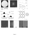
- ZIF films prepared on HOPG prepared as described above were examined by optical and scanning electron microscopy (SEM). A sharp change in contrast was observed at the air/precursor-solution interface beyond which the film had a uniform contrast indicating that the film was smooth, continuous, and macroscopically uniform ( Fig. 1f and 1g ).
- Atomic force microscopy (AFM) imaging near the interface confirmed that the ZIF film is indeed continuous and has a thickness of ca. 2 nm ( Fig. 1c and d ). 4 and 6 nm thick films were obtained by increasing the growth time from 5 min to 10 and 15 min, respectively ( Fig. 1e ). A discrete, 2 nm, increase in film thickness suggests a crystalline order.
- Macroscopic films could be obtained on polycrystalline graphene synthesized by chemical vapor deposition on a Cu foil ( Fig. 1f and 1g ) .
- Scanning electron microscope (SEM) measurements were performed on a Teneo Scanning Electron Microscope operating at 1 kV.
- TEM images and selected-area electron diffraction (SAED) images were obtained with a Talos F200X microscope operated at 200 kV.
- TEM images for patterns on silicon nitride were obtained on a ThermoFisher TF30 TEM operating at 300 kV.
- AC-HRTEM Low-dose aberration corrected high resolution TEM
- FEI G2 Titan 60-300 electron microscope at 300 kV using a Gatan K2 direct-detection camera in electron counting mode.
- the AC-HRTEM images were acquired with the dose fractionation function, and each image stack is composed of 120 frames with 0.05 s exposure for each frame, with a total electron dose of ⁇ 60 e - ⁇ -2 .
- the raw image was denoised by using an average background subtraction filter (ABSF).
- ABSF average background subtraction filter
- the CTF correction was performed based on the defocus value determined from the amorphous thon rings in the Fourier transform, and the projected electrostatic potential was simulated by the QSTEM software (QSTEM V2, 31). Simulated ED pattern was carried out by using Singlecrystal module of CrystalMaker software.
- AFM images and modulus measurement were recorded on a Bruker MultiMode 8 AFM.
- modulus measurement a Bruker Tap525A rectangular probe was used and calibrated with standard sample sapphire, polystyrene and HOPG.
- XPS were carried out on an Axis Supra (Kratos Analytical) using the monochromated K x-ray line of an aluminium anode.
- Synchrotron GIXRD was carried out at beamline BM01, Swiss-Norwegian beamline (SNBL) at the European Synchrotron Radiation Facility (ESRF) with wavelength of 0.683 ⁇ .
- the 2DZIF/graphene/PTMSP film was transferred on Si/SiO 2 wafer with 2DZIF layer facing the wafer. Then, the sample was annealed at 70°C for 4 h, to increase the adhesion between film and Si/SiO 2 wafer. After that, the sample was immersed in toluene for 12 h, to remove PTMSP layer.
- the AFM image of 2DZIF film with triangular morphology after 5 min of water etching was collected directly on the film with 2DZIF layer facing up.
- the 2DZIF/graphene/PTMSP film with triangular morphology was first scooped by glass slide with 2DZIF layer facing the slide, and a Si/SiO 2 wafer attached with double-sided carbon tape was pressed onto PTMSP layer.
- the 2DZIF/graphene/PTMSP film was transferred onto Si/SiO 2 wafer, resulting in 2DZIF layer facing up.
- AFM measurement of was carried out directly on the sample without any treatment.
- 2DZIF/graphene/PTMSP film was transferred on TEM grid with 2DZIF layer facing the TEM grid. Then, the sample was annealed at 70°C for 4 h, to increase the adhesion between film and TEM grid. After that, the sample was immersed in toluene for 12 h, to remove the PTMSP layer.
- the Brillouin zone was sampled at the gamma point.
- An energy cutoff of 60 Ry was used for the plane wave expansion of the wavefunctions.
- a kinetic energy cutoff of 480 Ry on the charge was used together with ultra-soft pseudopotentials ( Lejaeghere et al., 2016, Science 351, 6280 ; Prandini, et al., 2018, Comput. Mater. 4, 72 ).
- the relaxation was performed with the Perdew-Burke-Ernzerhof (PBE) functional ( Perdew et al., 1996, Phys. Rev. Lett. 77, 3865-3868 ) .
- the system was relaxed to the lowest energy configuration of atoms.
- the surface geometry had been optimized with the convergence thresholds of 1 ⁇ 10 -4 Ry and 3.28 ⁇ 10 -3 Ry/Bohr for the total energy and forces, respectively.
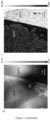
- Graphene supported ZIF film obtained by a method of the invention could be suspended on a holey transmission electron microscopy (TEM) grid ( Fig. 2a ) and it appeared that the film was devoid of large crystals and appeared uniform.
- Selected area electron diffraction (SAED) from a micrometer-sized area yielded three sets of diffraction patterns ( Fig. 2b ). The first two sets ((01), highlighted with grey circles) had six-fold symmetry originating from two slightly misoriented (by 3.0°) grains of graphene, while the last set had two-fold symmetry and belonged to a single grain of ZIF (highlighted with white circles), confirming that ZIF prepared on graphene was crystalline.
- the in-plane GIXRD pattern revealed sharp diffraction peaks, consistent with the peak positions obtained by the radial integration of the SAED pattern ( Fig. 2c ) confirming that the film formed on the graphitic substrate exhibits crystalline order.
- the sharpness of the GIXRD peak indicates that the grains were at least 0.1-0.2 ⁇ m in size.
- the presence of the order in the ZIF film when prepared over a graphitic substrate indicates a strong role of epitaxy in the formation of the ordered 2DZIF films.
- X-ray photoelectron spectroscopy (XPS) of the 2DZIF and aZIF films was carried out to gain further insights into their coordination environments ( Fig. 2d ).
- the N1s XPS data of 2DZIF when compared to that of ZIF-L layers (comparative) and a prototypical nonlayered ZIF (ZIF-8) revealed that both 2DZIF and ZIF-L yield two peaks (399.0 and 400.2 eV corresponding to N-Zn and N-H bonds, respectively) in contrast to a single peak (399.0 eV) from the ZIF-8 crystals.
- N-H abundant surface terminations
- the population of N-H species was significantly diminished for aZIF indicating a nonlayered amorphous structure.
- the layer in 2DZIF is composed of alternating 4-member ring (MR) and 6-MR chains while terminal 2-mIm linkers are present on both sides of the layer ( Fig. 2e and 3c ).
- the pore aperture of 2DZIF is constituted by the 6-MR and corresponds to a gap of 3.2 ⁇ . This value is in between that of ZIF-L (3.0 ⁇ ) and ZIF-8 (3.4 ⁇ ).
- ABC-HRTEM Aberration-corrected high-resolution TEM
- Fig. 3a highlights the morphological differences in ZIF-L and 2DZIF. While the layers in ZIF-L and 2DZIF are stacked along the c-axis, the former grows as a leaf-shaped layered crystal whereas the latter can form macroscopically uniform monolayer films. The unique leaf shape is formed because ZIF-L layers stack with first progressively increasing and then progressively decreasing lateral size along the b-axis.
- planar morphology of 2DZIF is determined by its epitaxial relationship with the graphitic lattice with near perfect registry along the b-direction (lattice mismatch of 0.2%) and a mismatch along the a-direction (5.36%, Fig. 3b .
- This allows unimpeded grain growth of 2DZIF on the graphitic lattice.
- ZIF-L and 2DZIF have orthorhombic lattices
- the unit-cell parameters of 2DZIF are distinct from those of ZIF-L where the latter has a significantly shorter parameter along the b (17.060 ⁇ ) axis ( Fig. 3c ).
- the grains of 2DZIF could be visualized by partial etching of 2DZIF films based on the well documented dissolution of ZIFs in water with reaction condition of 0.5 mM Zn 2+ , 4 mM 2-mIm for 4 min ( Fig. 3d ). After partial dissolution, the grain shape was triangular with a lateral size of 1-2 ⁇ m ( Fig. 3e ) consistent with earlier observations of domains in the sub-monolayer film. The three sides of the triangular grains could be assigned to be (110), (110) and (100) lattice planes, respectively, reported to be the minimum surface energy planes for ZIF layers ( Zhu et al ., 2017, supra ) . AFM images ( Fig. 3f ) confirmed that the grains have uniform thickness of ⁇ ca. 2 nm consistent with the structure of 2DZIF.
- the 2DZIF film (2DZIF grown on HOPG) was mechanically robust with Young's modulus of 8.1 ⁇ 2.1 GPa ( Fig. 3h & i) , comparable to that of the three-dimensional analogs ( Tan et al., 2010, PNAS 107, 9938-9943 ).
- Example 3 Gas performance of 2DZIF films according to the invention
- H2-sieving performance was assayed on 2DZIF films obtained as described in Example 1 using nanoporous graphene (NG) mechanically reinforced with a dense 250-nm-thick poly[1-(trimethylsilyl)propyne] (PTMSP) film where the NG/PTMSP film acts as a 2D substrate ( Fig. 4a ).
- the pores in NG were intentionally designed to be large (1.8 ⁇ 1.2 nm) ( He et al., 2019, Energy Environ. Sci., 12, 3305-3312 ) to rule out any molecular sieving from NG and to allow the determination of H 2 -sieving from the 2DZIF film.
- the resulting 2DZIF/graphene/PTMSP film was transferred to substrate (macroporous W support with 1-mm 2 -size testing area) for further characterizations or applications.
- the gas separation performance of the membranes was recorded on a homemade permeation setup.
- the pressure on the feed side was maintained at 2-8 bar and on the permeate side at 1 bar during the measurements. All measurements were done after reaching the steady state with argon as the sweep gas.
- the membranes were sealed with stainless-steel gasket.
- the composition of permeate was analysed using an online Hiden Analytical HPR-20 mass spectrometer.
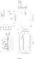
- the 2DZIF films resting on the macroporous metal foil support (area of 1 mm 2 ). exhibited a molecular cut-off for molecules larger than H 2 , indicating that gas transport was controlled by the 6-MR of 2DZIF ( Fig. 4b ).
- Centimeter-scale 2DZIF membrane could be also prepared, thanks to the highly uniform deposition of 2DZIF films on graphene (Fig. If and g), which also presents attractive permselective H 2 permeance ( Fig. 4f & g; Table 2) and H 2 /N 2 selectivity, in agreement with the smaller-area membranes.
- L is the thickness of membrane
- P i is permeability of the membrane material to gas i
- J i is permeance of the membrane material to gas i
- A is the effective area of membrane.
- J total , J support and J ZDZIF are permeance of total membrane, support layer and 2DZIF layer, respectively 2 .
- Example 4 Method of preparation of MOF films according to the invention on 2D porous substrates
- a 2D film of UiO-66-NH 2 was deposited on HOPG ( Fig. 5 ) under the following conditions of 1 mM Zr 4+ , 1 mM BDC-NH 2 aqueous solution for 2 min.
- Example 5 Method of preparation of ZIF films according to the invention on amorphous substrates
- the film crystallinity is determined by the interaction of molecular precursors during curse of the method of preparation according to the invention and that useful ultrathin amorphous films could be obtained by using an amorphous substrate in a method according to the invention.
- a Si/SiO 2 wafer with a 300-nm-thick oxide layer was provided as an amorphous substrate.
- the substrate was used as received.
- amorphous silicon nitride (SiN) was pre-treated with oxygen plasma for 10 min (29.6 W, 400 mTorr oxygen pressure) in a plasma cleaner (Harrick Plasma) to improve the surface reactivity and the pre-treated SiN layer was provided as an amorphous substrate.
- the amorphous substrate was then immersed in an ultradilute precursor solution ( ⁇ 2 mM Zn +2 and ⁇ 16 mM 2-methylimidazole (2-mIm), respectively) for a few minutes ( Fig. 6a ).
- an ultradilute precursor solution ⁇ 2 mM Zn +2 and ⁇ 16 mM 2-methylimidazole (2-mIm), respectively
- Fig. 6a a few minutes
- Example 6 Electron beam patterning of aZIF films obtained by a method according to the invention
- the aZIF film on the amorphous silicon nitride support obtained as described in Example 5 was subsequently exposed to a direct-write electron beam using 1:1 line- and space-patterns ranging from 10 to 40 nm in line width (or half pitch) using a Thermo Fisher Helios G4 UC Dual Beam microscope operating at 20 kV accelerating voltage and 400 pA beam current.
- the areal doses were 80 mC/cm 2 for all patterns ( Fig. 8a ).
- Fig. 8b After exposure and development in water for 24 h and blown dried in a stream of nitrogen gas, it was observed that the irradiated area was preserved while the non-irradiated area was dissolved ( Fig. 8b ), confirming aZIF as a negative-tone resist.
- the thickness of the remaining aZIF structure was determined to be ⁇ 25 nm by AFM ( Fig. 8c and d) .
- the resolution of the resulting pattern as exemplified by the well-resolved lines at 20 nm half pitch, is comparable to the state-of-the-art metal-containing resists ( Oleksak et al., 2014, ACS Appl. Mater.
- the ZIF films obtained on the Si/SiO 2 wafer substrate as described in Example 5 were observed as being macroscopically smooth, continuous, and uniform ZIF films.
Landscapes
- Chemical & Material Sciences (AREA)
- Chemical Kinetics & Catalysis (AREA)
- Inorganic Chemistry (AREA)
- Analytical Chemistry (AREA)
- Organic Chemistry (AREA)
- Engineering & Computer Science (AREA)
- General Chemical & Material Sciences (AREA)
- Oil, Petroleum & Natural Gas (AREA)
- Carbon And Carbon Compounds (AREA)
Abstract
The invention relates to methods for the preparation of ultrathin metal-organic frameworks (MOFs), in particular Zeolitic imidazolate frameworks (ZIFs) and uses thereof and resulting products thereof, in particular useful for the preparation of gas separation membranes, in particular for H2 sieving.
Description
- The present invention pertains generally to the field of preparation of metal-organic frameworks (MOFs), in particular Zeolitic imidazolate frameworks (ZIFs) and uses thereof.
- MOFs are organic-inorganic structures, highly porous structures that are obtained through precisely controlled structures in which two components of metal cations as nodes and organic molecules as bridges have been engineered.
- Zeolitic imidazolate frameworks (ZIFs) (Banerjee et al., 2008, Science 319, 939-943 ; Guillerm et al., 2014, Chem. Soc. Rev. 43, 6141-6172) are nanoporous ordered materials belonging to a class of metal-organic frameworks (MOFs) but exhibiting zeolitic topology and high chemical and thermal stability and that hold promise for applications in molecular separations (Zhou et al., 2018, Sci. Adv. 4:eaau1393 ; Ma et al., 2018, Science 361, 1008-1011), patterning (Stassen et al. 2013, CrystEngComm, 15, 9308-9311 ; Miao et al. 2022, Nat. Commun. 13, 420 ) and sensing (Lu et al., 2010, J. Am. Chem. Soc. 132, 7832-7833 ). ZIFs are constructed by linking Zn2+ or Co2+ ions with organic imidazolate (Im) linkers. As a result of their microporosity, ZIFs generally exhibit high CO2 uptake, making them suitable for CO2 based gas separation and storage. The presence of organic linkers enables various strategies to fine tune pore size and aperture as well as the pore polarity of ZIFs. Despite the wide variety in unraveled ZIF structures, not many different ZIF types have been applied in MMMs for gas separation.
- In particular, low-temperature synthesis and activation, high porosity, and Å-scale pore aperture of ZIF make it highly advantageous compared to other nanoporous materials especially for application in membrane-based separations. Å-scale biological channels represent the ideal design of selective layer because of their nanometer-scale pathlength (Epsztein et al., 2020, Nat. Nanotechnol. 15, 426-436 ).
- Their chemical and physical properties have been widely explored as a function of framework flexibility (Moggach et al., 2009, Angew. Chem. Int. Ed. 48, 7087-7089 ; Knebel et al. 2017, Science 358, 347-351) and structural defects (Bennett et al., 2017, Nat. Chem. 9, 11-16 ; Babu et al., 2019, Adv. Mater. 31, 1900855 ).
- ZIF-8 is constructed by linking 2-methylimidazolate with Zn2+ metal ions and has a sodalite (SOD) topology containing a cuboctahedral structure (Park, et al., 2006, Proc. Natl. Acad. Sci. U. S. A., 103, 10186-10191 ). Due to this unit cell structure permeation through ZIF-8 can occur in three dimensions. Moreover, the flexibility of the 2-methylimidazolate linkers in the ZIF-8 structure make the framework dynamic, where linker rotation can increase the crystallographic size of the pore aperture from 3.4 Å to a dynamic pore aperture of 4.0-4.2 Å (Qian et al., 2020, Chem. Rev., 120, pp. 8161-8266). The range of the ZIF-8 pore aperture size lies within the spectrum of the kinetic diameters of several industrial relevant gases, such as CO2 (3.3 Å), N2 (3.64 Å) and CH4 (3.8 Å), which can be regarded as the main motivation for the use of ZIF-8 in mixed matrix membranes (Essen et al., 2020, Separation and Purification Technology 260, 1, 118103 ).
- Amorphous MOFs exhibit unique physical and chemical properties due to the absence of anisotropy and crystalline grains (Bennett et al., 2018, Nat. Rev. Mater. 3, 431-440). They are especially attractive for lithographic patterning because of their improved homogeneity and processability compared to their polycrystalline counterparts.
- Numerous strategies for generating thin MOF coatings onto the supporting substrates had been developed (Crivello et al., 2021, Mater. Horiz. 2021,8, 168-178) which cand be categorized into two strategies: direct and indirect (Zhang et al., 2022, ACS Omega, 7 (21), 17765-17773). In the direct strategy, the MOF coating is in situ settled on the supporting substrates during MOF formation. In the indirect strategy, MOF coatings were obtained by launching the supporting substrate with the as-prepared free-standing MOF film, which was synthesized at the liquid-liquid or liquid-air interface (Bai et al., 2018, ACS Appl. Mater. Interfaces, 10, 25960-25966 ).
- In spite of the variety of the proposed strategies, several obstacles remain on the way to MOFs industrial applications, for example, poor processability in hydro-/solvothermal, expensive equipments required in electrochemical deposition, time consuming in stepwise method, specific substrate designed to direct the growth of MOF crystals in epitaxial growth. Recently, a new strategy was developed in an attempt to achieve MOF coatings independent from the substrates through the treatment of substrates with polyelectrolyte multilayers of polydimethyldiallyl ammonium chloride (PDDA), and tannic acid (TA) (Zhang et al., 2022, supra). However, the resulting layers are quite thick (2 µm), which limits the gas permeance.
- The realization of two-dimensional (2D) ZIF films with thickness down to that afforded by a single structural building unit is highly desired to make ZIF analogues to graphene and related 2D materials with an added advantage; the intrinsic nanoporosity of ZIF can be used to separate molecules while maximizing the permselective flux (Gascon et al., 2010, Angew. Chem. Int. Ed. 49, 1530-1532 ) and offer promising possibilities for removal of various environmental pollutants such as noxious gases, organic pollutants, heavy metals and radionuclides on ZIFs (Sun et al., 2022, Environ. Sci.: Nano, in press ).
- Another highly desirable feature is a nanometer-scale control over the film thickness which can allow one to fabricate nanoscale patterns. However, the realization of 2D crystalline and ultrathin amorphous ZIF films has remained elusive. While layered ZIFs such as ZIF-L (Chen et al. 2013, Chem. Commun., 49, 9500-9502 ), Zn2(bim)4 (Peng, et al., 2014) and analogs (Science 346, 1356-1359 ; Peng et al., 2017, Angew. Chem. 129, 9889-9893) have been reported, the individual ZIF layers in these materials have a small aspect ratio (100) which prevents the realization of continuous 2D ZIF films over a macroscopic length scale. The state-of-the-art of ZIF deposition methods yield polycrystalline films with thickness larger than 100 nanometers (He et al., 2018; Adv. Funct. Mater., 28, 1707427 ; Wei et al., 2020, Adv. Funct. Mater., 30, 1907089 ). This is mainly due to difficulty in achieving in-plane film growth without film thickening.
- Therefore, the development of new methods of fabricating MOF films (e.g. ZIF films), in particular 2D ZIF films in a precisely and controlled manner is highly attractive in view of the large-scale deployment of various possible applications for those materials that has been hampered so far by the above-described technical limitations.
- The present invention is based on the unexpected finding of a process that allows obtaining macroscopically uniform ultrathin amorphous MOF films, in particular two-dimensional ZIF (2DZIF) films on graphitic substrates, with thickness down to that of a single structural building unit (2 nm) with record high permselective H2 flux.
- A general object of this invention is to provide an efficient method of preparation of macroscopically uniform ZIF films with a nanometer-scale control over the film thickness.
- One of the specific objects of this invention is to provide an efficient method of preparation of 2D ZIF films under a fully controlled growth process with a resolution of a single layer.
- It is advantageous to provide a method of preparation of 2D ZIF film which allows the formation of such films with a homogeneous thickness over a large area in a time efficient manner.
- It is advantageous to provide a method of preparation of ultrathin (e.g., from about 2 nm to about 20 nm) 2D ZIF films on graphitic substrates and related 2D materials for membrane applications.
- It is advantageous to provide a method of preparation of ultrathin ZIF films which allows a precise precisely control of the desired film thickness and properties.
- It is advantageous to provide a method of preparation of ZIF films allowing preventing homogeneous nucleation in the bulk solution and promoting heterogeneous nucleation on the substrate surface.
- It is advantageous to provide a method of preparation of MOF, in particular, ZIF films at room temperature.
- It is advantageous to provide a method of preparation of MOF, in particular, ZIF films presenting a high mechanical strength.
- Objects of this invention have been achieved by providing a method for the preparation of a porous metal-organic framework according to
claim 1. - Disclosed herein is a method for the preparation of a MOF coated substrate comprising the steps of:
- a) Providing a substrate;
- b) Providing an ultra-diluted MOF metal precursor solution, wherein said an ultra-diluted MOF metal precursor solution contains ≤ 2mM of metal ions and ≤ 16 mM organic ligand;
- c) immersing the said substrate in the ultra-diluted MOF metal precursor solution for about 2 to about 20 min (e.g., 2 to 15 min);
- d) removing the obtained MOF coated substrate from the precursor solution, wherein the MOF coated substrate comprises a MOF layer from about 2 to about 20 nm coated on said substrate.
- In an advantageous embodiment, the obtained product in the form of ZIF coated graphene substrate is used for preparing a gas filter.
- It is advantageous to provide a gas selective membrane combining high H2 flux (typically higher than 1 mol m-2 s-1) and H2/N2 separation factor (typically higher than 20).
- Objects of this invention have been achieved by providing a graphitic substrate coated with two-dimensional crystalline ZIF (2DZIF) film according to claim 11.
- Objects of this invention have been achieved by providing a gas selective separation filter according to
claim 12. - Objects of this invention have been achieved by providing a use of a gas selective filter according to
claim 14. - Objects of this invention have been achieved by providing an amorphous substrate coated with an amorphous ZIF (aZIF) film according to
claim 15. - Objects of this invention have been achieved by providing a use of an amorphous porous substrate coated with amorphous ZIF (aZIF) film according to
claim 16. - Also disclosed herein is a graphitic substrate coated with a two-dimensional crystalline ZIF (2DZIF) film, wherein the said film's thickness is from about 2 nm to about 20 nm (e.g., about 2 nm) and the film's pore density from about 10 to about 60%, in particular 30% to about 60% (e.g., 50 %).
- Also disclosed herein is a gas selective filter wherein the graphene membrane is made with a method according to the invention.
- Also disclosed herein is a use of a gas selective filter comprising a membrane for gas separation, in particular for separating H2 from N2 and CH4.
- In an advantageous embodiment, the H2 permeance of the gas filter is from about 2'000 GPU to about 20'000 GPU, namely from about 7.7 × 10⁻⁷ to about 7.7 × 10⁻⁶ mol m-2 s-1 Pa-1 (e.g., 6 × 10⁻⁶ mol m-2 s-1 Pa-1 at 25°C under 2 bar).
- In an advantageous embodiment, the H2/N2 selectivity of a gas filter according to the invention is higher than 20, in particular from 20 to about 117 (e.g., from about 25 to 70) at 25°C under 2 bar.
- In an advantageous embodiment, the gas filter according to the invention according to the invention exhibits high permselective H2 flux.
- Also disclosed herein is an amorphous porous substrate coated with an amorphous ZIF (aZIF) film, wherein the said film's thickness is from about 8 nm to about 20 nm (e.g., about 10 nm).
- In an advantageous embodiment, the obtained product in the form of a ZIF coated amorphous porous substrate is used in imprinting or lithographic patterning processes (e.g., generating a patterned MOF coating on removable substrates).
- Also disclosed herein is a miniaturized catalytic, sensing, luminescent or biomedical (e.g. microfluidic or lab-on-a-chip device) device comprising an amorphous ZIF (aZIF) film according to the invention.
- According to a particular aspect, the method reported here will likely accelerate the development of 2D crystalline and ultrathin amorphous MOF films for applications ranging from separation membranes to patterning.
- Other features and advantages of the invention will be apparent from the claims, detailed description, and figures.
-
-
Figure 1 illustrates the synthesis ZIF films from ultradilute solutions as described in Example 1. a: Schematic representation of the formation of a ZIF film on a substrate. b: Composition diagram comparing the precursor solution composition used in the method of the invention with those reported in the literature (as detailed in Table 1). AFM (c) and the corresponding height profile (d) of a monolayer ZIF film on HOPG. e: Monolayer and multilayer ZIF films on HOPG with discrete thicknesses as a function of synthesis time. Error bars in this figure represent the standard deviation of measurement. f and g, Optical and SEM images of 2DZIF film on graphene/Cu foil, respectively, while SEM image was created from combining 43 × 42 = 1806 images by scanning the whole surface of the sample. -
Figure 2 presents the structure determination of 2DZIF films as described in Example 2. a: Bright-field TEM image of the 2DZIF film supported on suspended graphene, and (b) its corresponding SAED pattern. The pattern from graphene is identified with green circles and those from 2DZIF with white circles. c: In-plane GIXRD data from a 2DZIF film (middle) prepared on graphene/Si/SiO2 along with a radially integrated trace (bottom) of the SAED pattern shown in (b). d: N1s XPS spectra from ZIF-8, ZIF-L (comparative, not from the invention) and 2DZIF films. The N-Zn and N-H coordination environments are shown on the right. e: DFT-relaxed structure of the 2DZIF and a visualization of the 6-member-ring (6-MR) and its 3.2 Å gap. f: HRTEM image of the 2DZIF film lying flat on the hk0 plane, resting on suspended graphene, and (g) corresponding Fourier transform compared with the simulated diffraction pattern from the proposed structure oriented along the c-out-of-plane direction. h: Left: CTF-corrected image of the highlighted area in (f) based on a defocus value of -130 nm analysed from the Thon rings in the Fourier transform pattern. Right: simulated projected potential map along the [001] direction of 2DZIF. -
Figure 3 presents the characterization of the 2DZIF structure as described in Example 2 and its relationship with comparative ZIF-L. a: Schematic contrasting the arrangement of layers within a ZIF-L crystal with that of a monolayer 2DZIF according to the invention. b: Epitaxial relationship between the graphene lattice and 2DZIF. c: Structures of a 2DZIF layer according to the invention (left) and ZIF-L (right) viewed along the [001], [100], and [010] directions. d: Schematic illustration of the etching of 2DZIF in water. SEM (e) and AFM (f) images of the triangular grains of 2DZIF obtained by a short etching in water. g: AFM height profile corresponding to the line in (f); AFM image (h) and corresponding modulus map (i) of 2DZIF synthesized on HOPG. -
Figure 4 represents possible applications of 2DZIF obtained by a method of the invention. a: Schematic of a 2DZIF film supported on nanoporous graphene (NG) reinforced with PTMSP. b: H2, CO2, N2 and CH4 permeances of the PTMSP/NG support and the supported 2DZIF film on PTMSP/NG. c: 2DZIF membrane separation performance for an equimolar H2/N2 mixed feed. d: Comparison of the H2/N2 separation performance of 2DZIF membranes with the state-of-the-art membranes (as detailed inFig. 4e ). GO, CMP, and HOF refer to graphene oxide, conjugated microporous polymers and hydrogen-bonded organic frameworks, respectively. e: Gas permeance and ideal selectivity of a film of the invention compared to the state of the art in the literature; f: Optical photo of 1 cm scale 2DZIF membrane in module and (g) its schematic structure. -
Figure 5 presents the synthesis MOF films from ultradilute solutions according to a method of the invention as described in Example 4. a: Structure of the metal-organic framework UiO-66-NH2; b: SEM image of UiO-66-NH2 film synthesized on HOPG; c: AFM image and corresponding height profile for UiO-66-NH2 film synthesized on HOPG. (e) and (f) Bright-field TEM image of the UiO-66-NH2 film supported on suspended graphene and its corresponding SAED pattern, where grey and white circles are presenting diffraction from graphene and UiO-66-NH2, respectively. -
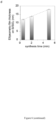
Figure 6 illustrates the synthesis ZIF films on Si/SiO2 as described in Examples 5 and 6 from ultradilute solutions. a: SEM and optical images of a ZIF film on Si/SiO2. b: AFM and the corresponding height profile (c) of the ZIF film on Si/SiO2; d: Ellipsometry of several ZIF films on Si/SiO2 wafer. -
Figure 7 presents the structure determination of aZIF films as described in Example 6. a: In-plane GIXRD data from an aZIF film prepared on Si/SiO2 b): N1s XPS spectra from aZIF. The N-Zn and N-H coordination environments are shown on the right. -
Figure 8 represents possible applications of aZIF obtained by a method of the invention. a: Schematic of the patterning process. TEM (b) and AFM (c) images of nanoscale patterns made on an aZIF film. d: AFM height profile corresponding to the line in (c). - The expression "MOF" or "Metal organic framework" refers to uniform structured porous materials fabricated by linking inorganic and organic units by strong bonds (reticular synthesis) which consist in of metal ions or clusters coordinated to organic ligands to form one-, two-, or three-dimensional structures. The organic ligands included are sometimes referred to as "struts" or "linkers". The choice of metal and linker dictates the structure and hence properties of the MOF. For example, the metal's coordination preference influences the size and shape of pores by dictating how many ligands can bind to the metal and in which orientation. To describe and organize the structures of MOFs, a system of nomenclature has been developed and subunits of a MOF, called secondary building units (SBU), can be described by topologies common to several structures. Each topology, also called a net, is assigned a symbol ( Seidi et al., 2020, Materials (Basel).13(12): 2881 ; Furukawa et al., 2013, Science 341:1230444 ). For example, a Zr-MOF, UiO-66 is a «coordination polymer». The monomers, AKA "building blocks", are bdc and Zr6O4 (OH)4 clusters. UiO-66 is the progenitor of a family of zirconium-based MOFs: the same Zr6O4 (OH)4 clusters found in UiO-66 serve as SBUs for a whole class of materials displaying a wide range of topologies, accessible by employing linkers having specific geometrical and symmetrical features. For example, Zeolitic imidazolate frameworks (ZIFs) is a subclass of MOFs, formed in zeolite topologies with metal ions and imidazolate ligands and ZIF-8 is a Zn-Based MOF. Another example is UiO-66, a zirconium(IV)-based MOF, has an exceptional chemical and thermal stability attributing to a high coordination number (12) of the [Zr6(µ3-O)4(µ3-OH)4] core with bidentate benzene-1,4-dicarboxylic acid (BDC) ligand.
- The expression "2D substrate" refers to a 2D material, including graphitic substrates and hexagonal boron nitride (hBN) and the like.
- The expression "graphitic substrate" includes highly-oriented pyrolytic graphite (HOPG) or graphene or porous graphene substrates.
- HOPG is a highly pure and ordered form of synthetic graphite characterized by a low mosaic spread angle, meaning that the individual graphite crystallites are well aligned with each other. The best HOPG samples have mosaic spreads of less than 1 degree.
- The expression "amorphous substrate" refers to any material without crystallographic registery at its surface. It includes Si/SiO2 wafers, SiN, glass, ceramic and the like.
- The expression "MOF metal precursor solution" comprises metal ions such as Zn2+ or Co2+ or Zr+4, an organic ligand such as 2-methylimidazole or imidazole, or benzimidazole or 2-ethylimidazole or purine or benzene-1,4-dicarboxylic acid, and a solvent such as water. The choice of the metal ion and organic ligand depends on the nature of the MOF to be obtained and can be easily selected in the literature ( Seidi et al., 2020, Materials (Basel). 13(12): 2881 ).
- Referring to the figures, in particular first to
Fig. 1a , is provided an illustration of a method of preparation of a MOF coated on a substrate according to an embodiment of the invention. The illustrated method generally comprises the steps of: - a) Providing a 2D substrate;
- b) providing an ultra-dilute MOF metal precursor solution, wherein said an ultra-diluted MOF metal precursor solution contains ≤ 2mM of metal ions and ≤ 16 mM organic ligand;
- c) immersing the said substrate in the said ultra-diluted MOF metal precursor solution for about 2 to about 20 min;
- d) removing the obtained MOF coated 2D substrate from the precursor solution, wherein the MOF coated 2D substrate comprises a MOF layer from about 2 to about 20 nm coated on said 2D substrate.
- According to a particular aspect, the 2D substrate is a porous 2D substrate with a porosity from about 0.1 to about 30% and a thickness from about 0.3 to about 1 nm.
- According to a particular aspect, the 2D substrate is a porous 2D substrate with pore size from about 0.3 to about 5 nm.
- According to a particular aspect, the 2D substrate is a 2D porous graphite substrate with a porosity about 5 to about 20% (e.g., from about 10 to about 18 %) and thickness of about 0.3 to about 1.0 nm (e.g., 0.3 nm).
- According to another particular aspect, the 2D porous substrate is a HOPG substrate, for example with a thickness about 1 mm.
- According to another particular aspect, the 2D porous substrate is a 2D porous graphite substrate mechanically reinforced with a porous polymeric film (e.g., PTMSP or Teflon AF layer of about 50 to 1000 nm) or nanoporous carbon film with thickness of 100 to 1000 nm.
- According to a particular aspect, the porous metal-organic framework is a ZIF, in particular a Zn-based MOF.
- According to another particular aspect, the porous metal-organic framework is a Zr-MOF, in particular UiO-66.
- According to another particular aspect, the metal-organic framework is a ZIF and the ultra-diluted MOF metal precursor solution contains ≤ 2 mM of Zn2+ and ≤ 16 mM 2-methylimidazole (2mIm).
- According to another particular aspect, the ultra-diluted MOF metal precursor solution contains from about 0.5 to about 2 mM of Zn2+ (e.g., from about 1 to about 2 mM of Zn2+).
- According to another particular aspect, the ultra-diluted MOF metal precursor solution contains from about 4 to about 16 mM 2-methylimidazole (e.g., from about 8 to about 16 mM 2-methylimidazole).
- According to a particular aspect, the porous substrate is immersed in the ultra-diluted MOF metal precursor solution from 1 to about 10 minutes (e.g., about 2 to about 5 minutes).
- According to a particular aspect, a method according to the invention allows the preparation of a MOF, in particular a ZIF film under epitaxial condition, i.e. where the deposited film takes on a lattice structure and orientation identical to those of the substrate.
- According to a particular aspect, the resulting 2D ZIF coated porous graphene substrate is used for preparing a gas filter.
- According to a particular aspect, is provided a graphitic substrate coated with two-dimensional crystalline ZIF (2DZIF) film, wherein the said film's thickness is from about 2 to about 20 nm (e.g., from about 2 to about 18 nm, such as from about 2 to about 10 nm) and the film's pore density from about 30 to about 60% (e.g., 50 %).
- According to a particular aspect, is provided a graphitic substrate coated with two-dimensional crystalline ZIF (2DZIF) film according to the invention, wherein the size of the pores of the ZIF film is from about 0.25 to about 1 nm, preferably from about 0.3 to about 0.4 nm.
- According to a particular aspect, is provided a graphitic substrate coated with two-dimensional crystalline ZIF (2DZIF) film, wherein the crystalline structure comprises a pore aperture made of a six-membered zinc-imidazolate coordination ring with an effective van der Waals gap of about 3.2 Å estimated by a crystallography software (Diamond).
- According to a particular aspect, is provided a gas selective filter wherein the graphene membrane is prepared with a method according to the invention.
- According to a particular aspect, is provided a gas selective filter comprising a porous graphitic substrate coated with two-dimensional ZIF (2DZIF) film according to the invention.
- Also disclosed herein is gas selective filter selecting H2 from N2 comprising an assembly of graphene membranes according to the invention.
- Also disclosed herein is a use of a gas selective filter comprising a membrane for gas separation, in particular for separating H2 from N2.
- In an advantageous embodiment, the H2 permeance of the gas filter is from about 15'000 GPU to about 20'000 GPU, namely from about 50.2 × 10⁻⁷ to about 7.7 × 10⁻⁶ mol m-2 s-1 Pa-1 (e.g., 6 × 10⁻⁶ mol m-2 s-1 Pa-1) at 25°C under 2 bar.
- In an advantageous embodiment, the H2/N2 selectivity of a gas filter according to the invention is from about 50 to about 70 at 25°C.
- According to another aspect, is provided an illustration of a method of preparation of a MOF coated on a substrate according to an embodiment of the invention. The illustrated method generally comprises the steps of:
- a) Providing an amorphous substrate;
- b) providing an ultra-diluted MOF metal precursor solution, wherein said an ultra-diluted MOF metal precursor solution contains ≤ 2mM of metal ions and ≤ 16 mM organic ligand;
- c) immersing the said substrate in the said ultra-diluted MOF metal precursor solution for about 2 to about 20 min;
- d) removing the obtained amorphous MOF coated substrate, wherein the amorphous MOF coated substrate comprises a MOF layer from about 2 to about 20 nm coated on said amorphous substrate.
- According to a particular aspect, the amorphous substrate is a Si/SiO2 wafer.
- Also disclosed herein is an amorphous substrate coated with an amorphous ZIF (aZIF) film, wherein the said film's thickness is from about 8 nm to about 20 nm (e.g., about 10 to 19 nm).
- In an advantageous embodiment, the obtained product in the form of a ZIF coated amorphous porous substrate is used in imprinting or lithographic patterning processes (e.g., generating a patterned MOF coating on removable substrates). Patterned MOF can be used in microelectronics, electrochemical devices and in sensors.
- Also disclosed herein is a miniaturized catalytic, sensing, luminescent or biomedical (e.g. microfluidic or lab-on-a-chip device) device comprising an amorphous ZIF (aZIF) film according to the invention.
- According to a particular aspect, the method reported here will likely accelerate the development of 2D crystalline and ultrathin amorphous MOF films for applications ranging from separation membranes to patterning.
- Without willing being bound by any theory, it has been found that the film crystallinity is determined by the interaction of molecular precursors with the substrate ranging from epitaxy-determined order to amorphous films in the absence of any crystallographic registry.
- As can be seen on
Fig. 3b , only when the lattice mismatch between MOF and the substrate is small, the resulting MOF film is crystalline. For amorphous substrates, the obtained MOF structures are random. - According to another particular embodiment, is provided a gas selective filter comprising a 2D ZIF coated graphene membrane having a thickness of 2 to 10 nm wherein the size of the pores of the ZIF film is in the range of 0.25-1 nm, preferably 0.3-0.4 nm.
- According to another particular aspect, a method and of the invention further advantageously provides useful starting materials for the preparation of membranes suitable for separation H2 from N2 where a H2 permeance reaching 20'000 gas permeation units with H2/N2 selectivity reaching 52, at 25°C.
- The invention having been described, the following examples are presented by way of illustration, and not limitation.
- Zinc nitrate hexahydrate (Zn(NO3)2·6H2O) was purchased from Sigma-Aldrich. 2-methylimidazole (2-mIm) was from Chemie Brunschwig AG. HCl (32 wt%) was purchased from Reactolab S.A.. poly[1-(trimethylsilyl)-1-propyne] (PTMSP) was from ABCR. FeCl3 (97%) and Na2S2O8 was bought from Sigma-Aldrich. Cu foil (50 mm, 99.9%) were purchased from STREM. Toluene (AR) and methanol (AR) were from Fischer. All chemicals were used without further purifications. Si/SiO2 wafers were purchased from University Wafer Inc. Si/SiO2 wafer with single layer graphene was bought from Ted Pella. Highly oriented pyrolytic graphite (HOPG) (ZYA quality, GRAS/1.0×7×7) was purchased from ScanSens. Silicon nitride TEM supports (50 nm silicon nitride film on a 200 µm silicon frame with nine viewing windows, each 0.1 × 0.1 mm) were purchased from Ted Pella.
- Various substrates 2D porous graphite substrates were used as substrates in a method according to the invention.
- A 2D graphite substrate such as highly-oriented pyrolytic graphite (HOPG) or graphene/Si/SiO2 is provided.
- The 2D graphite substrate was prepared depending on the envisioned applications. Examples are provided below.
- A single-layer graphene (SLG) was synthesized by using low-pressure CVD of methane on copper foil following the literature for example as described in Huang et al., 2021, Sci. Adv. 7:eabf0116 . Before the synthesis, the copper foil was annealed at 1077°C in a H2/Ar atmosphere for 60 min. Then, CO2 (100 mL/min) and H2 (8 mL/min) flow was introduced successively, each for 30 min, to remove the contaminations. At last, CH4 (24 mL/min) and H2 (8 mL/min) flow was used to grow single-layer graphene on copper film for 30 min at pressure of 460 mTorr.
- After the synthesis of single-layer graphene, an O2 plasma cleaner, EQ-PCE-3, 13.56 Mhz, 17 W) was carried out to introduce nanopores. Briefly, the atmosphere in the plasma chamber was exchanged by O2 flow to pressure around 50 mTorr. Then, a plasma was generated for 4 s to etch SLG to get nanoporous graphene (NG). After the plasma treatment, a solution of Poly(1-trimethylsilyl-1-propyne) (PTMSP) in toluene (1.25 wt%) was spin-coated on NG at 1000 rpm for 30 s and 2000 rpm for 30 s, respectively. After that, the sample was placed in ambient air at room temperature overnight. Then, copper foil was etched by a combination of FeCl3 (0.5 M in water), HCl (0.1 M in water) and water. Then, the obtained graphene/PTMSP film is used as a substrate in step b).
- For the synthesis of 1 cm scale 2DZIF membrane, 1 wt% of Teflon in GALDEN perfluorinated fluid was spin-coated on NG at 300 rpm for 60 s, and heated at 60°C for 3 h. After that, the sample was put into a membrane module for the gas separation test, while Cu foil facing up. This allowed etching of Cu by a 10 wt% Na2S2O8 aqueous solution. Then, the obtained graphene/teflon film is used as a 2D substrate in step b).
- The 2D substrate was then immersed in an ultradilute precursor solution (≤ 2 mM Zn+2 and ≤ 16 mM 2-methylimidazole (2-mIm), respectively) for a few minutes (
Fig. 1a ). First, in a petri dish containing 29 ml of Zn(NO3)2 aqueous solution at room temperature the 2D graphite substrate was partially immersed. Then, 1 ml of 2-mIm aqueous solution was added. After an incubation time of few minutes, the substrate was removed to stop the reaction. - The obtained ZIF films on graphitic substrates are referred to as 2DZIF. The use of such ultradilute solutions for the growth of ZIF films has not been reported before (
Fig. 1b ) and as compared under Table 1 below:Table 1 ZIFs Zn(NO3)2 (Wt. %) 2-mIm (Wt.%) H2O (Wt.%) Reaction temperature Reaction Time Reference Comparative ZIF-L 1.42 3.13 95.45 RT 4 h Wang et al., 2020, ACS Appl. Nano Mater. 3, 3839-3846 Comparative ZIF-L 0.72 1.59 97.69 RT 4 h Kim et al., 2018, J. Membr. Sci. 549, 260-266 Comparative ZIF-L 0.065 8.21 91.725 RT 14 h Zhang et al., 2018, New J. Chem. 42, 6719-6726 Comparative ZIF-L 0.36 3.56 96.08 RT 4 h Wang et al., 2019, Comparative ZIF-L 1.38 3.26 95.36 RT 1 h Han et al., 2020, J. Mater. Chem., 8, 25028-25034 Comparative ZIF-L 0.72 1.59 97.69 RT 4 h Zhu et al., 2019, RSC Adv., 9, 23390-23399 Comparative ZIF-L 0.83 1.82 97.35 30 °C 1 h Yuan et al., 2019, Adv. Mater. 31, 1807161 Comparative ZIF-L 1.26 5.56 93.18 RT 30 min Pan et al., 2011, Chem. Commun. 47, 2071-2073 2DZIF 0.059 0.13 99.811 RT ≤15 min From the invention - When a graphene/PTMSP film was used as a 2D substrate, a 2-min reaction in Zn(NO3)2, 2 mM and 2-mIm, 16 mM aqueous solution was used, and the resulting 2DZIF/graphene/PTMSP film was transferred to a macroporous substrate (e.g. macroporous W support with 1-mm2-size testing area) for further characterizations or applications.
- When a Teflon supported NG substrate was used as 2D substrate, a 10 min reaction time in (Zn(NO3)2, 2 mM and 2-mIm, 16 mM) solution was carried out.
- When HOPG was used as a substrate, a growth solution of 1 mM Zn2+ and 8 mM 2-mIm and reaction time of about 5 min was used.
- The ZIF films obtained by a method according to the invention were further characterized by various techniques as follows.
- ZIF films prepared on HOPG prepared as described above were examined by optical and scanning electron microscopy (SEM). A sharp change in contrast was observed at the air/precursor-solution interface beyond which the film had a uniform contrast indicating that the film was smooth, continuous, and macroscopically uniform (
Fig. 1f and 1g ). Atomic force microscopy (AFM) imaging near the interface confirmed that the ZIF film is indeed continuous and has a thickness of ca. 2 nm (Fig. 1c and d). 4 and 6 nm thick films were obtained by increasing the growth time from 5 min to 10 and 15 min, respectively (Fig. 1e ). A discrete, 2 nm, increase in film thickness suggests a crystalline order. A fitting of film thickness with the number of probable layers using the method described below yielded a monolayer thickness of 2 nm. Macroscopic films could be obtained on polycrystalline graphene synthesized by chemical vapor deposition on a Cu foil (Fig. 1f and 1g ). Scanning electron microscope (SEM) measurements were performed on a Teneo Scanning Electron Microscope operating at 1 kV. Powder X-ray diffraction (PXRD) data were collected at a Bruker D8 Discover diffractometer with a Lynxeye XE detector, operated at 40 kV, 400 mA for Cu Kα (λ = 1.5406 Å) at ambient temperature and pressure. Bright-field transmission electron microscopy (TEM) images and selected-area electron diffraction (SAED) images were obtained with a Talos F200X microscope operated at 200 kV. TEM images for patterns on silicon nitride were obtained on a ThermoFisher TF30 TEM operating at 300 kV. - Low-dose aberration corrected high resolution TEM (AC-HRTEM) was performed on a Cs-corrected FEI G2 Titan 60-300 electron microscope at 300 kV, using a Gatan K2 direct-detection camera in electron counting mode. The AC-HRTEM images were acquired with the dose fractionation function, and each image stack is composed of 120 frames with 0.05 s exposure for each frame, with a total electron dose of ~60 e-Å-2. The raw image was denoised by using an average background subtraction filter (ABSF). The CTF correction was performed based on the defocus value determined from the amorphous thon rings in the Fourier transform, and the projected electrostatic potential was simulated by the QSTEM software (QSTEM V2, 31). Simulated ED pattern was carried out by using Singlecrystal module of CrystalMaker software.
- AFM images and modulus measurement were recorded on a
Bruker MultiMode 8 AFM. For modulus measurement, a Bruker Tap525A rectangular probe was used and calibrated with standard sample sapphire, polystyrene and HOPG. XPS were carried out on an Axis Supra (Kratos Analytical) using the monochromated K x-ray line of an aluminium anode. Synchrotron GIXRD was carried out at beamline BM01, Swiss-Norwegian beamline (SNBL) at the European Synchrotron Radiation Facility (ESRF) with wavelength of 0.683 Å. - For the AFM sample preparation of 2DZIF film on graphene/PTMSP substrate, the 2DZIF/graphene/PTMSP film was transferred on Si/SiO2 wafer with 2DZIF layer facing the wafer. Then, the sample was annealed at 70°C for 4 h, to increase the adhesion between film and Si/SiO2 wafer. After that, the sample was immersed in toluene for 12 h, to remove PTMSP layer.
- The AFM image of 2DZIF film with triangular morphology after 5 min of water etching was collected directly on the film with 2DZIF layer facing up. Specifically, the 2DZIF/graphene/PTMSP film with triangular morphology was first scooped by glass slide with 2DZIF layer facing the slide, and a Si/SiO2 wafer attached with double-sided carbon tape was pressed onto PTMSP layer. As a result, the 2DZIF/graphene/PTMSP film was transferred onto Si/SiO2 wafer, resulting in 2DZIF layer facing up. AFM measurement of was carried out directly on the sample without any treatment.
- Similar to sample preparation for AFM, 2DZIF/graphene/PTMSP film was transferred on TEM grid with 2DZIF layer facing the TEM grid. Then, the sample was annealed at 70°C for 4 h, to increase the adhesion between film and TEM grid. After that, the sample was immersed in toluene for 12 h, to remove the PTMSP layer.
- The simulation of 2DZIF structure was carried out by Density functional theory (DFT) calculations. At first, the reported ZIF-L structure ( Chen et al. 2013, Chem. Commun., 49, 9500-9502 ) was imported into Forcite module in Material Studio software (Accelrys, San Diego, CA) to calculate the initial structural model, and unit-cell was set to be orthorhombic and a = 24.0 Å, b = 20.0 Å, c = 20.0 Å, α = 90°, β = 90°, γ = 90°, respectively, while the connectivity was kept. The calculation task was geometry optimization. The quality was set to be fine, and 'smart' algorithm was selected. After that, van der Waals DFT calculations were performed using the Quantum ESPRESSO package (Giannozzi et al., 2009, J. Phys. Condens. Matter, 21, 390052 ; Giannozzi et al., 2017, J. Phys. Condens. Matter, 29, 465901).
- The Brillouin zone was sampled at the gamma point. An energy cutoff of 60 Ry was used for the plane wave expansion of the wavefunctions. A kinetic energy cutoff of 480 Ry on the charge was used together with ultra-soft pseudopotentials (Lejaeghere et al., 2016, Science 351, 6280 ; Prandini, et al., 2018, Comput. Mater. 4, 72). The relaxation was performed with the Perdew-Burke-Ernzerhof (PBE) functional (Perdew et al., 1996, Phys. Rev. Lett. 77, 3865-3868). The system was relaxed to the lowest energy configuration of atoms. The surface geometry had been optimized with the convergence thresholds of 1 × 10⁻⁴ Ry and 3.28 ×10⁻³ Ry/Bohr for the total energy and forces, respectively.
- Graphene supported ZIF film obtained by a method of the invention could be suspended on a holey transmission electron microscopy (TEM) grid (
Fig. 2a ) and it appeared that the film was devoid of large crystals and appeared uniform. Selected area electron diffraction (SAED) from a micrometer-sized area yielded three sets of diffraction patterns (Fig. 2b ). The first two sets ((01), highlighted with grey circles) had six-fold symmetry originating from two slightly misoriented (by 3.0°) grains of graphene, while the last set had two-fold symmetry and belonged to a single grain of ZIF (highlighted with white circles), confirming that ZIF prepared on graphene was crystalline. The fact that a single 2DZIF grain could grow over two slightly misoriented graphene grains indicates that epitaxial growth can accommodate small lattice mismatch. Diffraction pattern from 2DZIF, typically representing a single grain, was observed from every single spot over a large area. Based on the diffraction pattern, a and b lattice parameters of 2.4 and 2.0 nm, respectively, could be fitted. Synchrotron grazing incidence X-ray diffraction (GIXRD) was carried out of a 10-nm-thick ZIF film on graphene resting on a Si/SiO2 wafer prepared as described above. The in-plane GIXRD pattern revealed sharp diffraction peaks, consistent with the peak positions obtained by the radial integration of the SAED pattern (Fig. 2c ) confirming that the film formed on the graphitic substrate exhibits crystalline order. The sharpness of the GIXRD peak (FWHM of 0.035°) indicates that the grains were at least 0.1-0.2 µm in size. - The presence of the order in the ZIF film when prepared over a graphitic substrate indicates a strong role of epitaxy in the formation of the ordered 2DZIF films.
- X-ray photoelectron spectroscopy (XPS) of the 2DZIF and aZIF films was carried out to gain further insights into their coordination environments (
Fig. 2d ). The N1s XPS data of 2DZIF when compared to that of ZIF-L layers (comparative) and a prototypical nonlayered ZIF (ZIF-8) revealed that both 2DZIF and ZIF-L yield two peaks (399.0 and 400.2 eV corresponding to N-Zn and N-H bonds, respectively) in contrast to a single peak (399.0 eV) from the ZIF-8 crystals. This is consistent with the presence of abundant surface terminations (N-H) in the 2DZIF layers. In comparison, the population of N-H species was significantly diminished for aZIF indicating a nonlayered amorphous structure. - To gain insight into the structure of 2DZIF, structural relaxation based on density functional theory (DFT) was carried out starting with the a and b lattice parameters obtained by SAED and layer thickness from AFM. The relaxed structure has an orthorhombic space group Cmce with the following structural parameters; a = 24.196 Å, b = 19.719 Å, c = 20.908 Å, α = 90°, β = 90°, and γ = 90°. The layer in 2DZIF is composed of alternating 4-member ring (MR) and 6-MR chains while terminal 2-mIm linkers are present on both sides of the layer (
Fig. 2e and3c ). The pore aperture of 2DZIF is constituted by the 6-MR and corresponds to a gap of 3.2 Å. This value is in between that of ZIF-L (3.0 Å) and ZIF-8 (3.4 Å). - Aberration-corrected high-resolution TEM (AC-HRTEM) imaging of the 2DZIF film suspended on a TEM grid was carried out along the [001] crystallographic direction (
Fig. 2f ). The imaging was carried out using a low-dose beam condition (Zhu et al., 2017, Nat. Mater. 16, 532-536) to minimize damages to the beam sensitive 2DZIF lattice. Indeed, the obtained HRTEM image revealed the high crystallinity of the 2DZIF film. The corresponding Fourier transform validated the c-out-of-plane orientation of the film and was consistent with the simulated electron diffraction pattern from a film lying flat along the same orientation (Fig. 2g ). Projection along the c-out-of-plane axis from the contrast transfer function (CTF) corrected image revealed alternating chains of 4-MR and 6-MR (Fig. 2h , left), consistent with the simulated [0001]-projected electrostatic potential map of 2DZIF structure obtained by density functional theory (DFT) structural relaxation (Fig. 2h , right). - The epitaxial relationship of 2DZIF with the graphitic lattice plays an important role in determining its unique 2D structure and morphology especially when contrasted against the closely related material, ZIF-L.
Fig. 3a highlights the morphological differences in ZIF-L and 2DZIF. While the layers in ZIF-L and 2DZIF are stacked along the c-axis, the former grows as a leaf-shaped layered crystal whereas the latter can form macroscopically uniform monolayer films. The unique leaf shape is formed because ZIF-L layers stack with first progressively increasing and then progressively decreasing lateral size along the b-axis. In contrast, the planar morphology of 2DZIF is determined by its epitaxial relationship with the graphitic lattice with near perfect registry along the b-direction (lattice mismatch of 0.2%) and a mismatch along the a-direction (5.36%,Fig. 3b . This allows unimpeded grain growth of 2DZIF on the graphitic lattice. While both ZIF-L and 2DZIF have orthorhombic lattices, the unit-cell parameters of 2DZIF are distinct from those of ZIF-L where the latter has a significantly shorter parameter along the b (17.060 Å) axis (Fig. 3c ). - The grains of 2DZIF could be visualized by partial etching of 2DZIF films based on the well documented dissolution of ZIFs in water with reaction condition of 0.5 mM Zn2+, 4 mM 2-mIm for 4 min (
Fig. 3d ). After partial dissolution, the grain shape was triangular with a lateral size of 1-2 µm (Fig. 3e ) consistent with earlier observations of domains in the sub-monolayer film. The three sides of the triangular grains could be assigned to be (110), (110) and (100) lattice planes, respectively, reported to be the minimum surface energy planes for ZIF layers (Zhu et al., 2017, supra). AFM images (Fig. 3f ) confirmed that the grains have uniform thickness of ~ ca. 2 nm consistent with the structure of 2DZIF. - The 3.2 Å gap in the 6-MR of 2DZIF is attractive for sieving H2 (kinetic diameter of 2.89 Å) from larger gas molecules such as CO2 (3.30 Å), N2 (3.64 Å), and CH4 (3.80 Å) (Zhu et al., 2019, RSC Adv. 9, 2339-23399; Yang, et al., 2021, Sci. Bull. 66, 1869-1876).
- The 2DZIF film (2DZIF grown on HOPG) was mechanically robust with Young's modulus of 8.1 ± 2.1 GPa (
Fig. 3h & i), comparable to that of the three-dimensional analogs (Tan et al., 2010, PNAS 107, 9938-9943). - H2-sieving performance was assayed on 2DZIF films obtained as described in Example 1 using nanoporous graphene (NG) mechanically reinforced with a dense 250-nm-thick poly[1-(trimethylsilyl)propyne] (PTMSP) film where the NG/PTMSP film acts as a 2D substrate (
Fig. 4a ). The pores in NG were intentionally designed to be large (1.8 ± 1.2 nm) (He et al., 2019, Energy Environ. Sci., 12, 3305-3312 ) to rule out any molecular sieving from NG and to allow the determination of H2-sieving from the 2DZIF film. The resulting 2DZIF/graphene/PTMSP film was transferred to substrate (macroporous W support with 1-mm2-size testing area) for further characterizations or applications. - The gas separation performance of the membranes was recorded on a homemade permeation setup. The pressure on the feed side was maintained at 2-8 bar and on the permeate side at 1 bar during the measurements. All measurements were done after reaching the steady state with argon as the sweep gas. The membranes were sealed with stainless-steel gasket. The composition of permeate was analysed using an online Hiden Analytical HPR-20 mass spectrometer.
- The permeances, J i , of gas i was calculated by Eq. S1
where X i is the molar flow rate of component i across the membrane area (A) and ΔP i is the transmembrane pressure difference for the component i. The selectivity α ij of two gases (i and j, where i is the faster permeating gas) was calculated by Eq. S2 - The 2DZIF films, resting on the macroporous metal foil support (area of 1 mm2). exhibited a molecular cut-off for molecules larger than H2, indicating that gas transport was controlled by the 6-MR of 2DZIF (
Fig. 4b ). The H2 permeance was large (>15'000 gas permeation units or GPU; 1 GPU = 3.35 × 10⁻¹⁰ mol m-2 s-1 Pa-1) similar to that from the support film (indicating a negligible transport resistance from the 2DZIF layer. - When an equimolar H2:N2 mixture was probed with feed pressure of 2 bar, a H2 permeance of 17300 GPU with a H2/N2 separation factor of 115 could be obtained (
Fig. 4c ). Another membrane when tested under a high-pressure feed (8 bar), exhibited a high H2 flux of 2.8 mol m-2 s-1 and H2/N2 separation factor of 52. This performance constitutes one of the best combinations of H2 flux and H2/N2 separation factor (Fig. 4d ) as detailed inFig. 4e , wherein the following references are cited: 12: Mao et al., 2014, ACS Appl. Mater. ; 13: Huang et al., 2018, Adv. Mater. Interfaces, 5, 1800287 ; 14: Zhong et al., 2014, Carbon 72, 242-249 ; 15: Zhong et al. 2015, J. Mater. Chem. A 3, 15715-15722 ; 16: Li et al., 2016, Nat. Commun., 7, 11315 ; 17: Eum et al., 2019, Angew. Chemie. Int. Ed. 131, 16542-16546 ; 18: De Vos et al., 1998, Science 279, 1710-1711; 19: Poshusta et al., 1998, Ind. Eng. Chem. Res. 37, 3924-3929 ; 20: Guo et al., 2020, Angew. Chemie. Int. Ed., 59, 6284-634 ; 21: Liu et al., 2020, Nat. Commun., 11, 1633 ; 22: Lei et al., 2021, Nat. Commun., 12, 268 ; 23: Feng et al., 2020, Angew. Chemie. Int. Ed. 59, 3840-3845 ; Huang et al., 2021, Sci. Adv. 7, eabf0116). - Centimeter-scale 2DZIF membrane could be also prepared, thanks to the highly uniform deposition of 2DZIF films on graphene (Fig. If and g), which also presents attractive permselective H2 permeance (
Fig. 4f & g; Table 2) and H2/N2 selectivity, in agreement with the smaller-area membranes.Table 2 H2 permeance (GPU) CO2 permeance (GPU) N2 permeance (GPU) CH4 permeance (GPU) H2/CO2 H2/N2 H2/CH4 NG/Teflon (support film) 2450 2290 610 390 1.1 4.0 6.3 2DZIF synthesized on NG/Teflon support film 2180 340 110 80 6.4 19.8 27.3 Intrinsic performance of the 2DZIF layer∗ 19781 399 134 101 50 148 195 ∗ Based on the resistance model as described below. -
- Where L is the thickness of membrane, Pi is permeability of the membrane material to gas i, Ji is permeance of the membrane material to gas i, and A is the effective area of membrane.
-
-
- Where Jtotal , Jsupport and JZDZIF are permeance of total membrane, support layer and 2DZIF layer, respectively2.
-
- We will have the intrinsic H2 permeance of 2DZIF J2DZIF = 19781 (GPU).
- In order to support that the method of preparation can be applied to other MOFs and is not limited to ZIFs, a 2D film of UiO-66-NH2 was deposited on HOPG (
Fig. 5 ) under the following conditions of 1 mM Zr4+, 1 mM BDC-NH2 aqueous solution for 2 min. - SEM image from panel b confirmed its flat and smooth of UiO-66-NH2 thin film and its thickness is 1.8 nm from the result of AFM measurement (
Fig. 5c and 5d ). Finally, its crystallinity was checked by electron diffraction, and two patterns were observed, where grey circles and white circles represent graphene and UiO-66-NH2, respectively (Fig. 5e and 5f ). - Altogether, those data support that the method of the invention achieves the preparation of MOFs, in particular ZIFs, as macroscopically uniform crystalline 2D films from an ultradilute solution. The 2DZIF film yields exceptional H2-sieving performance, thanks to the ordered 2D structure with a high density of 6-MR with 3.2 Å gap, making such a film the ultimate selective layer for membrane application.
- It was surprisingly found that the film crystallinity is determined by the interaction of molecular precursors during curse of the method of preparation according to the invention and that useful ultrathin amorphous films could be obtained by using an amorphous substrate in a method according to the invention.
- A Si/SiO2 wafer with a 300-nm-thick oxide layer was provided as an amorphous substrate. The substrate was used as received.
- For electron patterning application, amorphous silicon nitride (SiN) was pre-treated with oxygen plasma for 10 min (29.6 W, 400 mTorr oxygen pressure) in a plasma cleaner (Harrick Plasma) to improve the surface reactivity and the pre-treated SiN layer was provided as an amorphous substrate.
- The amorphous substrate was then immersed in an ultradilute precursor solution (≤ 2 mM Zn+2 and ≤ 16 mM 2-methylimidazole (2-mIm), respectively) for a few minutes (
Fig. 6a ). First, in a petri dish containing 29 ml of Zn(NO3)2 aqueous solution at room temperature the amorphous substrate was partially immersed. Then, 1 ml of 2-mIm aqueous solution was added. After an incubation time of 2-15 minutes, the substrate was removed to stop the reaction. The obtained ZIF films on amorphous substrates are referred to as aZIF. - The aZIF film on the amorphous silicon nitride support obtained as described in Example 5 was subsequently exposed to a direct-write electron beam using 1:1 line- and space-patterns ranging from 10 to 40 nm in line width (or half pitch) using a Thermo Fisher Helios G4 UC Dual Beam microscope operating at 20 kV accelerating voltage and 400 pA beam current. The areal doses were 80 mC/cm2 for all patterns (
Fig. 8a ). - After exposure and development in water for 24 h and blown dried in a stream of nitrogen gas, it was observed that the irradiated area was preserved while the non-irradiated area was dissolved (
Fig. 8b ), confirming aZIF as a negative-tone resist. The thickness of the remaining aZIF structure was determined to be ~25 nm by AFM (Fig. 8c and d). The resolution of the resulting pattern, as exemplified by the well-resolved lines at 20 nm half pitch, is comparable to the state-of-the-art metal-containing resists (Oleksak et al., 2014, ACS Appl. Mater. Interfaces, 6, 2917-2921 ; Xu et al., 2018, Chem. Mater. 30, 4124-4133) which are an emerging class of material that hold promise in extreme ultraviolet lithography and electron beam lithography (Stowers et al., 2009, Microelectron. Eng. 86, 730-733 ; Luo et al., 2020, RSC Adv. 10, 8385-8395 ; Manouras et al., 2020, ). - The simple fabrication of ultrathin ZIF films according to the present invention applied to amorphous substrates could accelerate the development of new ZIF-based resist materials for lithographic applications (Gangnaik et al., 2017, Review, Chem. Mater., 29, 1898-1917 , Tu et al., 2021, Nat. Mater. 20, 93-99 , Ghash et al., 2021, Chem. Mater., 33, 5681-5689 ; Conrad et al., 2018, Angew. Chem. Int. Ed., 57, 13592-13597 ).
- The ZIF films obtained on the Si/SiO2 wafer substrate as described in Example 5 (
Fig. 6a ) were observed as being macroscopically smooth, continuous, and uniform ZIF films. AFM of one of these films, prepared using 2 mM Zn2+ and 16 mM 2-mIm and growth time of 10 s, confirmed that the film is smooth with thickness near 8 nm (Fig. 6b and 6c ). Ellipsometry of several ZIF films on Si/SiO2 wafer, prepared by varying the synthesis time, 10 s -5 min, indicated that the film thickness could be tuned in the range of 8-18 nm (Fig. 6d ). - In X-ray diffraction (GIXRD), no diffraction from those ZIF films prepared directly on Si/SiO2 wafer confirmed that that these films were amorphous.
- Altogether, those data support that the method of the invention achieves the preparation of ZIFs, as macroscopically uniform amorphous films from an ultradilute solution. on non-epitaxial substrates yields macroscopically smooth amorphous ZIF films, which can be used as negative-tone resists yielding pattern features down to 10 nm.
- Those ultrathin amorphous films are promising for advancing the limit of nanoscale patterning.
Claims (16)
- A method for the preparation of a metal-organic framework (MOF)coated substrate comprising the steps of:a) Providing a substrate;b) providing an ultra-diluted MOF metal precursor solution, wherein said an ultra-diluted MOF metal precursor solution contains ≤ 2mM of metal ions and ≤ 16 mM organic ligand;c) immersing the said substrate in the ultra-diluted MOF metal precursor solution for about 2 to about 20 min;d) removing the obtained the MOF coated substrate from the precursor solution, wherein the MOF coated substrate comprises a MOF layer from about 2 to about 20 nm coated on said substrate.
- The method of claim 1 wherein the support is a 2D substrate, in particular a 2D porous graphitic substrate.
- The method of claim 2 wherein the 2D substrate is selected from a HOPG substrate, a graphene/PTMSP substrate or a nanoporous graphene/teflon substrate.
- The method of claim 1, wherein the porous MOF is a ZIF, in particular a Zn-based MOF.
- The porous metal-organic framework is a ZIF, in particular a Zn-based MOF.
- The method of any preceding claim wherein the porous metal-organic framework is a Zr-MOF, in particular UiO-66.
- The method of any one of claims 1 to 4, wherein the MOF is a ZIF and the ultra-diluted MOF metal precursor solution contains ≤ 2 mM of Zn2+ and ≤ 16 mM 2-methylimidazole (2mIm).
- The method of any one of claims 1 to 4 and 7, wherein the ultra-diluted MOF metal precursor solution contains from 1 to about 2 mM of Zn2+.
- The method of any one of claims 1 to 4 and 7, wherein the ultra-diluted MOF metal precursor solution contains from about 8 to about 16 mM 2-methylimidazole.
- The method of any preceding claims wherein the substrate is immersed in the ultra-diluted MOF metal precursor solution from 1 to about 10 minutes (e.g. about 2 to 5 minutes).
- A graphitic substrate coated with two-dimensional crystalline ZIF (2DZIF) film, wherein the said film's thickness is from about 2 to about 20 nm (e.g. from about 2 to about 18 nm, such as from about 2 to about 10 nm) and the film's pore density from about 10% to about 60%, in particular about 30% to about 60% (e.g. 50%).
- A gas selective filter for separating H2 and N2 comprising a graphene membrane comprising a graphitic substrate coated with two-dimensional ZIF (2DZIF) film obtained from a method according to anyone of claims 1 to 10.
- A gas selective filter comprising a membrane comprising a membrane comprising a porous graphitic substrate coated with two-dimensional ZIF (2DZIF) film according to claim 11.
- Use of a gas selective filter according to claim 12 or 13 for separating H2 and N2.
- An amorphous substrate coated with an amorphous ZIF (aZIF) film, wherein the said film's thickness is from about 8 nm to about 20 nm (e.g. about 10 to 19 nm).
- Use of an amorphous porous substrate coated with amorphous ZIF (aZIF) film in an imprinting or lithographic patterning process.
Priority Applications (3)
| Application Number | Priority Date | Filing Date | Title |
|---|---|---|---|
| EP22207344.7A EP4368285A1 (en) | 2022-11-14 | 2022-11-14 | Method of preparation of ultrathin metal-organic frameworks & uses thereof |
| EP23804705.4A EP4619150A2 (en) | 2022-11-14 | 2023-11-13 | Method of preparation of ultrathin metal-organic frameworks & uses thereof |
| PCT/EP2023/081603 WO2024104957A2 (en) | 2022-11-14 | 2023-11-13 | Method of preparation of ultrathin metal-organic frameworks & uses thereof |
Applications Claiming Priority (1)
| Application Number | Priority Date | Filing Date | Title |
|---|---|---|---|
| EP22207344.7A EP4368285A1 (en) | 2022-11-14 | 2022-11-14 | Method of preparation of ultrathin metal-organic frameworks & uses thereof |
Publications (1)
| Publication Number | Publication Date |
|---|---|
| EP4368285A1 true EP4368285A1 (en) | 2024-05-15 |
Family
ID=84358217
Family Applications (1)
| Application Number | Title | Priority Date | Filing Date |
|---|---|---|---|
| EP22207344.7A Withdrawn EP4368285A1 (en) | 2022-11-14 | 2022-11-14 | Method of preparation of ultrathin metal-organic frameworks & uses thereof |
Country Status (1)
| Country | Link |
|---|---|
| EP (1) | EP4368285A1 (en) |
Cited By (3)
| Publication number | Priority date | Publication date | Assignee | Title |
|---|---|---|---|---|
| CN118904291A (en) * | 2024-09-09 | 2024-11-08 | 浙江工业大学 | Application of hollow carbon nano-particle material as adsorbent for adsorbing gold ions |
| CN119318890A (en) * | 2024-11-08 | 2025-01-17 | 国能神东煤炭集团有限责任公司 | Long-range conjugated organic/inorganic gas separation membrane and preparation method thereof |
| CN119345918A (en) * | 2024-12-24 | 2025-01-24 | 北京化工大学 | A composite MOF membrane for gas separation and preparation method thereof |
Citations (1)
| Publication number | Priority date | Publication date | Assignee | Title |
|---|---|---|---|---|
| WO2019186134A1 (en) * | 2018-03-29 | 2019-10-03 | G2O Water Technologies Limited | Membranes comprising a layer of metal organic framework particles |
-
2022
- 2022-11-14 EP EP22207344.7A patent/EP4368285A1/en not_active Withdrawn
Patent Citations (1)
| Publication number | Priority date | Publication date | Assignee | Title |
|---|---|---|---|---|
| WO2019186134A1 (en) * | 2018-03-29 | 2019-10-03 | G2O Water Technologies Limited | Membranes comprising a layer of metal organic framework particles |
Non-Patent Citations (61)
| Title |
|---|
| BABU DEEPU J. ET AL: "Crystal Engineering of Metal-Organic Framework Thin Films for Gas Separations", ACS SUSTAINABLE CHEMISTRY & ENGINEERING, vol. 7, no. 1, 6 December 2018 (2018-12-06), US, pages 49 - 69, XP093048713, ISSN: 2168-0485, DOI: 10.1021/acssuschemeng.8b05409 * |
| BABU ET AL., ADV. MATER., vol. 31, 2019, pages 1900855 |
| BAI ET AL., ACS APPL. MATER. INTERFACES, vol. 10, 2018, pages 25960 - 25966 |
| BANERJEE ET AL., SCIENCE, vol. 319, 2008, pages 939 - 943 |
| BENNETT ET AL., NAT. CHEM., vol. 9, 2017, pages 11 - 16 |
| BENNETT ET AL., NAT. REV. MATER., vol. 3, 2018, pages 431 - 440 |
| CHEN ET AL., CHEM. COMMUN., vol. 49, 2013, pages 9500 - 9502 |
| CONRAD ET AL., ANGEW. CHEM., vol. 57, 2018, pages 13592 - 13597 |
| CRIVELLO ET AL., MATER. HORIZ., vol. 8, 2021, pages 168 - 178 |
| DE VOS ET AL., SCIENCE, vol. 279, 1998, pages 710 - 1711 |
| EPSZTEIN ET AL., NAT. NANOTECHNOL., vol. 15, 2020, pages 426 - 436 |
| ESSEN ET AL., SEPARATION AND PURIFICATION TECHNOLOGY, vol. 260, no. 7, 2020, pages 118103 |
| EUM ET AL., ANGEW. CHEMIE, vol. 131, 2019, pages 16542 - 16546 |
| FENG ET AL., ANGEW. CHEMIE, vol. 59, 2020, pages 3840 - 3845 |
| FURUKAWA ET AL., SCIENCE, vol. 341, 2013, pages 1230444 - 1359 |
| GANGNAIK ET AL., REVIEW, CHEM. MATER., vol. 29, 2017, pages 1898 - 1917 |
| GASCON ET AL., ANGEW. CHEM., vol. 49, 2010, pages 1530 - 1532 |
| GHASH ET AL., CHEM. MATER., vol. 33, 2021, pages 5681 - 5689 |
| GIANNOZZI ET AL., J. PHYS. CONDENS. MATTER, vol. 21, 2009, pages 390052 |
| GIANNOZZI ET AL., J. PHYS. CONDENS. MATTER, vol. 29, 2017, pages 465901 |
| GUANGWEI HE ET AL: "Electrophoretic Nuclei Assembly for Crystallization of High-Performance Membranes on Unmodified Supports", ADVANCED FUNCTIONAL MATERIALS, WILEY - V C H VERLAG GMBH & CO. KGAA, DE, vol. 28, no. 20, 12 March 2018 (2018-03-12), pages n/a, XP072414956, ISSN: 1616-301X, DOI: 10.1002/ADFM.201707427 * |
| GUILLERM ET AL., CHEM. SOC. REV., vol. 43, 2014, pages 6141 - 6172 |
| HE ET AL., ADV. FUNCT. MATER., vol. 28, 2018, pages 1707427 |
| HE ET AL., ENERGY ENVIRON. SCI., vol. 12, 2019, pages 3305 - 3312 |
| HE GUANGWEI ET AL: "Supporting Information: Electrophoretic Nuclei Assembly for Crystallization of High-Performance Membranes on Unmodified Supports", ADVANCED FUNCTIONAL MATERIALS, 12 March 2018 (2018-03-12), pages 1707427, XP093047851, Retrieved from the Internet <URL:https://api.wiley.com/onlinelibrary/tdm/v1/articles/10.1002%2Fadfm.201707427> [retrieved on 20230517], DOI: 10.1002/adfm.201707427 * |
| HUANG ET AL., ADV. MATER. INTERFACES, vol. 5, 2018, pages 1800287 |
| HUANG ET AL., SCI. ADV., vol. 7, 2021, pages eabf0116 |
| KNEBEL ET AL., SCIENCE, vol. 358, 2017, pages 347 - 351 |
| LEI ET AL., NAT. COMMUN., vol. 12, 2021, pages 268 |
| LEJAEGHERE ET AL., SCIENCE, vol. 351, 2016, pages 6280 |
| LI ET AL., NAT. COMMUN., vol. 7, 2016, pages 11315 |
| LIU ET AL., NAT. COMMUN., vol. 11, 2020, pages 1633 |
| LU ET AL., J. AM. CHEM. SOC., vol. 132, 2010, pages 7832 - 7833 |
| LUO ET AL., SC ADV., vol. 10, 2020, pages 8385 - 8395 |
| MA ET AL., SCIENCE, vol. 361, 2018, pages 1008 - 1011 |
| MANOURAS ET AL., NANOMATERIALS, vol. 10, 2020, pages 1593 |
| MAO ET AL., CS APPL. MATER. INTERFACES, vol. 6, 2014, pages 4473 - 4479 |
| MIAO ET AL., NAT. COMMUN., vol. 13, 2022, pages 420 |
| MOGGACH ET AL., ANGEW. CHEM., vol. 48, 2009, pages 7087 - 7089 |
| OLEKSAK ET AL., ACS APPL. MATER. INTERFACES, vol. 6, 2014, pages 2917 - 2921 |
| PARK ET AL., PROC. NATL. ACAD. SCI. U. S. A., vol. 103, 2006, pages 10186 - 10191 |
| PENG ET AL., ANGEW. CHEM., vol. 129, 2017, pages 9889 - 9893 |
| PERDEW ET AL., PHYS. REV. LETT., vol. 77, 1996, pages 3865 - 3868 |
| POSHUSTA ET AL., IND. ENG. CHEM. RES., vol. 37, 1998, pages 3924 - 3929 |
| PRANDINI ET AL., COMPUT. MATER., vol. 4, 2018, pages 72 |
| QIAN ET AL., CHEM. REV., vol. 120, 2020, pages 8161 - 8266 |
| SEIDI ET AL., MATERIALS (BASEL), vol. 13, no. 12, 2020, pages 2881 |
| STASSEN ET AL., CRYSTENGCOMM, vol. 15, 2013, pages 9308 - 9311 |
| STOWERS ET AL., MICROELECTRON. ENG., vol. 86, 2009, pages 730 - 733 |
| SUN ET AL., ENVIRON. SCI.: NANO, 2022 |
| TAN ET AL., PNAS, vol. 107, 2010, pages 9938 - 9943 |
| TU ET AL., NAT. MATER., vol. 20, 2021, pages 93 - 99 |
| WEI ET AL., ADV. FUNCT. MATER., vol. 30, 2020, pages 1907089 |
| XU ET AL., CHEM. MATER., vol. 30, 2018, pages 4124 - 4133 |
| YANG ET AL., SCI. BULL., vol. 66, 2021, pages 1869 - 1876 |
| ZHANG ET AL., ACS OMEGA, vol. 7, no. 21, 2022, pages 17765 - 17773 |
| ZHONG ET AL., CARBON, vol. 72, 2014, pages 242 - 249 |
| ZHONG ET AL., J. MATER. CHEM. A, vol. 3, 2015, pages 15715 - 15722 |
| ZHOU ET AL., SCI. ADV., vol. 4, 2018, pages eaaul393 |
| ZHU ET AL., NAT. MATER., vol. 16, 2017, pages 532 - 536 |
| ZHU ET AL., RSC ADV., vol. 9, 2019, pages 2339 - 23399 |
Cited By (3)
| Publication number | Priority date | Publication date | Assignee | Title |
|---|---|---|---|---|
| CN118904291A (en) * | 2024-09-09 | 2024-11-08 | 浙江工业大学 | Application of hollow carbon nano-particle material as adsorbent for adsorbing gold ions |
| CN119318890A (en) * | 2024-11-08 | 2025-01-17 | 国能神东煤炭集团有限责任公司 | Long-range conjugated organic/inorganic gas separation membrane and preparation method thereof |
| CN119345918A (en) * | 2024-12-24 | 2025-01-24 | 北京化工大学 | A composite MOF membrane for gas separation and preparation method thereof |
Similar Documents
| Publication | Publication Date | Title |
|---|---|---|
| EP4368285A1 (en) | Method of preparation of ultrathin metal-organic frameworks & uses thereof | |
| Wang et al. | Secondary growth of covalent organic frameworks (COFs) on porous substrates for fast desalination | |
| Lai | Development of ZIF-8 membranes: opportunities and challenges for commercial applications | |
| Lee et al. | Preparation of Ni-MOF-74 membrane for CO2 separation by layer-by-layer seeding technique | |
| US11173454B2 (en) | Self-supporting MOF membranes | |
| Shamsaei et al. | A one-dimensional material as a nano-scaffold and a pseudo-seed for facilitated growth of ultrathin, mechanically reinforced molecular sieving membranes | |
| Li et al. | Growth of ZnO self-converted 2D nanosheet zeolitic imidazolate framework membranes by an ammonia-assisted strategy | |
| US9248400B2 (en) | Zeolitic imidazolate framework membranes and methods of making and using same for separation of C2− and C3+ hydrocarbons and separation of propylene and propane mixtures | |
| Li et al. | Green synthesis of ZIF-8 tubular membranes from a recyclable 2-methylimidazole water-solvent solution by ZnO nanorods self-converted strategy for gas separation | |
| Xu et al. | Preparation of ZIF-8 membranes supported on ceramic hollow fibers from a concentrated synthesis gel | |
| Ranjan et al. | Microporous metal organic framework membrane on porous support using the seeded growth method | |
| Lai et al. | Highly-selective MOF-303 membrane for alcohol dehydration | |
| Neelakanda et al. | Polymer supported ZIF-8 membranes by conversion of sputtered zinc oxide layers | |
| Zhang et al. | Nanoporous film-mediated growth of ultrathin and continuous metal–organic framework membranes for high-performance hydrogen separation | |
| Mao et al. | Enhanced gas separation through well-intergrown MOF membranes: seed morphology and crystal growth effects | |
| Lo et al. | Pseudopolymorphic seeding for the rational synthesis of hybrid membranes with a zeolitic imidazolate framework for enhanced molecular separation performance | |
| Zhu et al. | Highly hydrogen-permselective zeolitic imidazolate framework ZIF-8 membranes prepared on coarse and macroporous tubes through repeated synthesis | |
| Zhang et al. | A simple seed-embedded method to prepare ZIF-8 membranes supported on flexible PESf hollow fibers | |
| Chen et al. | Fabrication of MIL-96 nanosheets and relevant c-oriented ultrathin membrane through solvent optimization | |
| Jin et al. | Oriented growth of large-area metal-organic framework ZIF-8 membrane for hydrogen separation | |
| Hu et al. | Honeycomb ZIF‐67 Membrane With Hierarchical Channels for High‐Permeance Gas Separation | |
| EP4619150A2 (en) | Method of preparation of ultrathin metal-organic frameworks & uses thereof | |
| CN113413778B (en) | A method for preparing MOF film by seed-assisted supercritical technology and its gas separation application | |
| Yan et al. | Asymmetric pore windows in pillar-layered metal–organic framework membranes for H2/CO2 separation | |
| Yue et al. | Synthesis of metal–organic framework particles and thin films via nanoscopic metal oxide precursors |
Legal Events
| Date | Code | Title | Description |
|---|---|---|---|
| PUAI | Public reference made under article 153(3) epc to a published international application that has entered the european phase |
Free format text: ORIGINAL CODE: 0009012 |
|
| STAA | Information on the status of an ep patent application or granted ep patent |
Free format text: STATUS: THE APPLICATION HAS BEEN PUBLISHED |
|
| AK | Designated contracting states |
Kind code of ref document: A1 Designated state(s): AL AT BE BG CH CY CZ DE DK EE ES FI FR GB GR HR HU IE IS IT LI LT LU LV MC ME MK MT NL NO PL PT RO RS SE SI SK SM TR |
|
| STAA | Information on the status of an ep patent application or granted ep patent |
Free format text: STATUS: THE APPLICATION IS DEEMED TO BE WITHDRAWN |
|
| 18D | Application deemed to be withdrawn |
Effective date: 20241116 |