EP4368060A1 - Eyeglasses case with lateral spring means and cam - Google Patents
Eyeglasses case with lateral spring means and cam Download PDFInfo
- Publication number
- EP4368060A1 EP4368060A1 EP23208302.2A EP23208302A EP4368060A1 EP 4368060 A1 EP4368060 A1 EP 4368060A1 EP 23208302 A EP23208302 A EP 23208302A EP 4368060 A1 EP4368060 A1 EP 4368060A1
- Authority
- EP
- European Patent Office
- Prior art keywords
- lid
- container
- cam
- case according
- opening
- Prior art date
- Legal status (The legal status is an assumption and is not a legal conclusion. Google has not performed a legal analysis and makes no representation as to the accuracy of the status listed.)
- Granted
Links
Images

Classifications
-
- A—HUMAN NECESSITIES
- A45—HAND OR TRAVELLING ARTICLES
- A45C—PURSES; LUGGAGE; HAND CARRIED BAGS
- A45C11/00—Receptacles for purposes not provided for in groups A45C1/00-A45C9/00
- A45C11/04—Spectacle cases; Pince-nez cases
-
- A—HUMAN NECESSITIES
- A45—HAND OR TRAVELLING ARTICLES
- A45C—PURSES; LUGGAGE; HAND CARRIED BAGS
- A45C13/00—Details; Accessories
- A45C13/005—Hinges
- A45C13/007—Hinges with spring means
Definitions
- the present invention relates to an eyeglasses case for carrying eyeglasses with a spring and cam system for controlling opening and closing thereof.
- a further necessary characteristic is the need for secure and irreversible closing of the case when not operated by the user, in order to avoid the undesirable risk of the eyeglasses accidentally falling out and the lens being damaged.
- Cases are known where, for this purpose, a hinge is mounted or formed integrally on the back of the case (rear long surface the container), said hinge being able to be associated with a spring designed to automatically close the case and prevent the accidental reopening thereof.
- the technical problem which is posed, therefore, is to provide a case for eyeglasses which is provided with a system for controlling the opening/closing movement able to solve the problems of the prior art.
- the system should not reduce excessively the containing volume of the case and should be able to be covered so to avoid the risk of the moving parts being exposed to the end user.
- a further object of the invention consists in the possibility of allowing opening of the case, by moving the lid with one hand only.
- a preferred example of embodiment of a eyewear case according to the present invention comprises a lid 10 ( Fig. 1 ) formed by a central body 11 extending with its greatest dimension in a longitudinal direction and provided with two opposite sides 12 extending in the vertical direction.
- Each side 12 comprises in particular:
- the case according to the invention furthermore comprises a container 20 ( Fig. 3 ) comprising a central body 21 extending with its greatest dimension in the longitudinal direction and joined to two opposite sides 22 extending in the vertical direction.
- each side 22 comprises a respective opening 23 configured to house a cam element 30.
- the opening 23 is in particular shaped to allow insertion of the cam element 30 in the side 22 and subsequent locking thereof both in the axial direction and in rotation of the cam element 30 with respect to the side 22; as will emerge more clearly below, preferably, the opening 23 defines respective seats 23a,23b in the side of the container, designed to form respective stops 24a,24a,24b; 25a,25b for correct and stable housing of the cam element 30.
- lid and container may have only one opening or recess on only one of the two sides.
- end-of-travel means (not shown) which are designed to limit the opening of the lid; an example of these end-of-travel means may be defined by a further pin present in the side 12 of the lid and designed to cooperate with a corresponding stop defined by the container 20.
- the preferred cam element 30 shown has a substantially circular shape and has:
- the teeth 31a,31b are arranged opposite each other along a first diameter of the cam element and the fingers 33d are arranged opposite each other along a second diameter of the cam 30.
- the cam In the central position ( Fig. 8, 9 ) the cam has a hole 34 suitable for coupling with the rotation pin 12a of the lid 10 and a suitably shaped (raised) arm 35, which is eccentric with respect to the rotation pin and is designed to interact with a spring 13 during opening of the lid, in order to cause deformation thereof, increasing the load thereof and therefore generating a recall reaction of said spring into the initial position for closing the lid.
- the spring 13 is a preferred example of a spring element designed to be mounted on the side 12 of the lid 10 and to cooperate with the respective cam 30 integrally joined with the side 22 of the container 20 so as to push the lid towards the closed position.
- the spring element 13 comprises a first part 13a fixed to the side 12 of the lid, for example by means of respective shaped engagement features 13b for engaging over a respective pin of the further pins 12b, and a deformable arm 13c designed to be arranged in operative engagement on the cam arm 35.
- the cam element 30 may be axially inserted inside the respective opening 23 of the container 20, by coupling the rotation pin 12a of the lid 10 together with the hole 34 in the cam, without stressing the latter.
- the teeth 31a and 31b are engaged inside the respective shaped seats 23a and 23b until they engage with the respective stops 25a, 25b, thereby axially constraining the cam 30 with respect to the container 20, and the elastic locking teeth 33d are forced to snap-engage with the respective anti-rotation stops 24a,24b, resulting in locking of the relative rotation of the cam with respect to the container 20, beyond the stops 24a and 24b.
- the arrangement of the spring 13 in operative coupling with the cam 30 causes the spring 13, once the cam 30 has been positioned, to be prestressed (with the arm 13c elastically deformed) in a stable closing position.
- At least one mechanical stop (not shown) of the container 20 is also provided in order to prevent excessive prestressing of the spring 13 and/or accidental rotation of the spring with respect to the container during rotation of the lid for opening or closing the case.
- the relative rotation between lid and cam will result in a deformation of the spring which will impart thereto first the prestress and then the working load and the consequent recall force which will push the lid again into the closed position.
- the container 20 and the lid 10 are coupled together along the respective opposite sides so that the lid may rotate, during opening/closing of the case, with respect to the container about a longitudinal axis of rotation, between a closed position ( Fig. 7 ) and a fully open position ( Fig. 5 ) in which the eyeglasses may be inserted/removed inside/from the containing volume of the case, in particular in a direction of insertion substantially perpendicular to the longitudinal axis X-X and parallel to the lateral flanks of the case.
- opening of the lid 10 is performed by rotation thereof about the pin 12a, for example in an anti-clockwise direction, relative to the container 20.
- the possibility is provided of using forms and dimensions of the eccentric cam in order to produce different recall forces in the different relative angular positions of the container and lid.
- the shape of the spring and the dimensions (thickness and height) of the spring may also be different.
- Alternative embodiments may not have the two pins for engagement with the spring element 13, which could be replaced, for example, by different engagement structures, such as a single pin or a locating seat for a spring, also with a different form, without substantially modifying its function.
- the volume of the cam and the rotation pins and the extension of the spring in its working positions may be essentially contained within a thin disc which has its axis parallel to the axis of rotation and may therefore be easily contained within the sides of the case; in addition to this, the correct positioning of the rotation axis according to the invention is able to provide an eyeglasses case with a compact volume of the container/lid assembly both in the open position and in the closed position and with an improved working volume compared to the prior art.
- the positioning, on the sides, of the lid operating device also allows the case to be opened/closed with one hand and the moving parts to be covered so as to ensure greater safety for the end user.
Landscapes
- Closures For Containers (AREA)
- Purses, Travelling Bags, Baskets, Or Suitcases (AREA)
Abstract
Description
- The present invention relates to an eyeglasses case for carrying eyeglasses with a spring and cam system for controlling opening and closing thereof.
- It is known in the technical sector relating to the commercialization of eyeglasses that there is the need to provide eyeglasses cases which are able to contain the eyeglasses and which must have characteristics of rigidity, in order to protect the eyeglasses, and a simple and secure closing system for inserting/removing the eyeglasses, as well as having an attractive design and being able to be carried in the pocket or bag of the user.
- A further necessary characteristic is the need for secure and irreversible closing of the case when not operated by the user, in order to avoid the undesirable risk of the eyeglasses accidentally falling out and the lens being damaged.
- Cases are known where, for this purpose, a hinge is mounted or formed integrally on the back of the case (rear long surface the container), said hinge being able to be associated with a spring designed to automatically close the case and prevent the accidental reopening thereof.
- While fulfilling their function, these cases nevertheless have drawbacks which reduce their functionality since they are limited by the position of the rotation axis of the hinge which must necessarily be situated outside the containing volume of the case. The obligatory position of the rotation axis limits the possible movement mechanisms, spring prestressing systems and, finally, design solutions which may be offered.
- The technical problem which is posed, therefore, is to provide a case for eyeglasses which is provided with a system for controlling the opening/closing movement able to solve the problems of the prior art.
- It is also required that the system should not reduce excessively the containing volume of the case and should be able to be covered so to avoid the risk of the moving parts being exposed to the end user.
- A further object of the invention consists in the possibility of allowing opening of the case, by moving the lid with one hand only.
- In connection with these problems, it is also preferable that such a case should be easy and inexpensive to produce and assemble and that the final weight thereof should be limited.
- These results are obtained according to the present invention by a case according to the characteristic features of Claim 1. Preferred embodiments are described in the dependent claims.
- Further details may be obtained from the following description of a nonlimiting example of embodiment of the subject of the present invention provided with reference to the attached drawings in which:
-
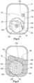
Figure 1 : shows a perspective view of a lid forming part of a case according to the present invention; -
Figure 2 : shows a schematic cross-sectional view of the lid according toFig. 1 with a recall spring mounted thereon; -
Figure 3 : shows a perspective view of a container forming part of a case according to the present invention; -
Figure 4 : shows a schematic perspective view of a guide cam element which can be mounted on the container according toFig.3 ; -
Figure 5 : shows a perspective view of a case according to the present invention in the assembled and open condition; -
Figure 6 : shows a schematic cross-sectional view of a side of the open case according toFig.5 ; -
Figure 7 : shows a perspective view of a case according to the present invention in the assembled and closed condition; and -
Figure 8 : shows a schematic cross-sectional view of a side of the closed case according toFig.7 ; -
Figure 9 : shows a schematic cross-sectional view of a side of the case according toFig. 7 , along a cross-sectional plane of the side of the container different from that shown inFig. 8 . - As shown in
Figs. 1-9 , a preferred example of embodiment of a eyewear case according to the present invention comprises a lid 10 (Fig. 1 ) formed by acentral body 11 extending with its greatest dimension in a longitudinal direction and provided with twoopposite sides 12 extending in the vertical direction. - Each
side 12 comprises in particular: - -- at least one
first pin 12a designed to form an axis of rotation for the lid; - -- at least two further locating
pins 12b, which form a preferred example of embodiment of engagement means for ashaped spring 13, the function of which will become clear below. - The case according to the invention furthermore comprises a container 20 (
Fig. 3 ) comprising acentral body 21 extending with its greatest dimension in the longitudinal direction and joined to twoopposite sides 22 extending in the vertical direction. - As shown in
Fig. 3 , eachside 22 comprises arespective opening 23 configured to house acam element 30. The opening 23 is in particular shaped to allow insertion of thecam element 30 in theside 22 and subsequent locking thereof both in the axial direction and in rotation of thecam element 30 with respect to theside 22; as will emerge more clearly below, preferably, theopening 23 definesrespective seats respective stops cam element 30. - Although shown with an
opening 23 for eachside 22, so as to favour more balanced relative movements of lid and container, it is envisaged that the latter may have only one opening or recess on only one of the two sides. Preferably, it is also possible to envisage end-of-travel means (not shown) which are designed to limit the opening of the lid; an example of these end-of-travel means may be defined by a further pin present in theside 12 of the lid and designed to cooperate with a corresponding stop defined by thecontainer 20. - The
preferred cam element 30 shown has a substantially circular shape and has: - -- an annular edge provided with projecting
teeth cam 30 inside the opening 23 in theside 22 of thecontainer 20; - --
recesses 32c extending towards the inside of the body of thecam 30 and with oppositely directed openings; each recess defines arespective finger 33d which is elastically deformable inwards (towards the axis of rotation) so as to facilitate insertion inside the opening 23 of the container and an opposite elastic reaction for stable positioning against the inner wall thereof, in particular an abutting arrangement (Fig. 9 ) against therespective stop seat - As shown, in a preferred embodiment, the
teeth fingers 33d are arranged opposite each other along a second diameter of thecam 30. - In the central position (
Fig. 8, 9 ) the cam has ahole 34 suitable for coupling with therotation pin 12a of thelid 10 and a suitably shaped (raised)arm 35, which is eccentric with respect to the rotation pin and is designed to interact with aspring 13 during opening of the lid, in order to cause deformation thereof, increasing the load thereof and therefore generating a recall reaction of said spring into the initial position for closing the lid. - As shown in
Fig. 8 , thespring 13 is a preferred example of a spring element designed to be mounted on theside 12 of thelid 10 and to cooperate with therespective cam 30 integrally joined with theside 22 of thecontainer 20 so as to push the lid towards the closed position. - In greater detail, the
spring element 13 comprises afirst part 13a fixed to theside 12 of the lid, for example by means of respectiveshaped engagement features 13b for engaging over a respective pin of thefurther pins 12b, and adeformable arm 13c designed to be arranged in operative engagement on thecam arm 35. - For assembly of the container, in a first assembly position, the
cam element 30 may be axially inserted inside therespective opening 23 of thecontainer 20, by coupling therotation pin 12a of thelid 10 together with thehole 34 in the cam, without stressing the latter. - By rotating the cam with a suitable tool, the
teeth shaped seats respective stops cam 30 with respect to thecontainer 20, and theelastic locking teeth 33d are forced to snap-engage with the respectiveanti-rotation stops container 20, beyond thestops - The arrangement of the
spring 13 in operative coupling with thecam 30 causes thespring 13, once thecam 30 has been positioned, to be prestressed (with thearm 13c elastically deformed) in a stable closing position. - In a preferred embodiment, at least one mechanical stop (not shown) of the
container 20 is also provided in order to prevent excessive prestressing of thespring 13 and/or accidental rotation of the spring with respect to the container during rotation of the lid for opening or closing the case. Advantageously, during opening of the case, the relative rotation between lid and cam will result in a deformation of the spring which will impart thereto first the prestress and then the working load and the consequent recall force which will push the lid again into the closed position. - In detail, the simultaneous engagement of the
elastic teeth 33d with thestops elements stops - As shown in
Figs. 5, 6 and 7 , once the case has been assembled, thecontainer 20 and thelid 10 are coupled together along the respective opposite sides so that the lid may rotate, during opening/closing of the case, with respect to the container about a longitudinal axis of rotation, between a closed position (Fig. 7 ) and a fully open position (Fig. 5 ) in which the eyeglasses may be inserted/removed inside/from the containing volume of the case, in particular in a direction of insertion substantially perpendicular to the longitudinal axis X-X and parallel to the lateral flanks of the case. - As shown in
Figs. 5 and 6 , opening of thelid 10 is performed by rotation thereof about thepin 12a, for example in an anti-clockwise direction, relative to thecontainer 20. - During the opening rotation of the
lid 10, thecam arm 35, resting on one end of thespring 13, causes compressive deformation thereof which forces thearm 13c of thespring 13 to be deformed towards thefixed arm 13a of the said spring. - By deforming in this direction, the spring load will be increased, producing a reaction which will push the lid towards the closed position.
- During closing rotation, if the lid is left free in the totally or partially open position, there will be a reaction of the spring which will tend to return into the rest position, therefore pushing against the
shaped arm 35 and generating a force which will cause the lid to close. - Once closing has been completed, the prestress imparted to the spring during assembly of the components will maintain a residual force which will tend to keep the case closed.
- According to the invention the possibility is provided of using forms and dimensions of the eccentric cam in order to produce different recall forces in the different relative angular positions of the container and lid.
- The shape of the spring and the dimensions (thickness and height) of the spring may also be different.
- By modifying the rigidity and prestressing of the spring it is possible to vary the degree of resistance to opening and the force which recalls the lid into the closed position.
- Alternative embodiments may not have the two pins for engagement with the
spring element 13, which could be replaced, for example, by different engagement structures, such as a single pin or a locating seat for a spring, also with a different form, without substantially modifying its function. - It is therefore clear how the volume of the cam and the rotation pins and the extension of the spring in its working positions may be essentially contained within a thin disc which has its axis parallel to the axis of rotation and may therefore be easily contained within the sides of the case; in addition to this, the correct positioning of the rotation axis according to the invention is able to provide an eyeglasses case with a compact volume of the container/lid assembly both in the open position and in the closed position and with an improved working volume compared to the prior art.
- The positioning, on the sides, of the lid operating device also allows the case to be opened/closed with one hand and the moving parts to be covered so as to ensure greater safety for the end user.
- Although described in connection with a number of embodiments and a number of preferred examples of implementation of the invention, it is understood that the scope of protection of the present patent is determined solely by the claims below.
Claims (15)
- Eyeglasses Case for eyeglasses comprising:- a container (20) comprising an elongated central body (21) with greatest dimension parallel to a longitudinal axis and two opposite sides (22) integrally joined to opposite ends of the central body;- a lid (10) comprising an elongated central body (11) with greatest dimension parallel to a longitudinal axis and two opposite sides (12) which are respectively integrally joined to opposite ends of the central body;the container (20) and the lid (10) being formed so as to be coupled along the respective opposite sides such that the lid can rotate for opening/closing the case relative to the container about a longitudinal axis of rotation, between a closed position and an open position;- spring means (13) mounted on the lid (10), characterized in that said spring means comprise at least one spring element (13) mounted on at least one of said sides (12) of the lid (10) and in that the at least one respective side (22) of the container (20) has an opening (23) which houses a cam element (30) arranged and configured to cooperate with the spring element so as to push the lid towards the closed position, the cam element (30) being stably housed in the respective side of the container so as to be rotationally fixed with respect thereto.
- Case according to Claim 1, characterized in that one or both of said sides (12) of the lid comprise/s a first pin (12a) designed to form the longitudinal axis of rotation for the lid.
- Case according to one of the preceding claims, wherein said at least one of said sides (12) of the lid comprises engagement means for mounting the respective spring element
- Case according to Claim 3, wherein said engagement means comprise one or more further locating pins (12b).
- Case according to one of the preceding claims, wherein said one opening (23) in the side of the container defines a pair of seats (23a,23b) for inserting and positioning the cam element (30).
- Case according to one of the preceding claims, wherein an outer annular edge of the cam element (30) is provided with teeth (31a,31b) designed to abut against corresponding stops (24a;24b) of the opening (22a) in the side of the container, in particular against a stop (24a;24b) defined by the respective seat (23a;23b) of the opening.
- Case according to one of the preceding claims, wherein the cam (30) has a hole (34) in a central position suitable for coupling with the rotation pin (12a) of the lid (10) and a shaped arm (35) which is eccentric with respect to the axis of rotation and designed to interact with the spring element (13) so as to cause a deformation thereof when the lid is rotationally operated relative to the container for opening the case.
- Case according to one of the preceding claims, wherein the cam (30) has locating elements configured to allow insertion into the opening of the side and prevent axial displacement and/or rotation of the cam element with respect to the container.
- Case according to one of the preceding claims, wherein the cam element (30) has a pair of recesses (32c) extending towards the inside of the cam body and with oppositely directed openings; each recess defining a respective tooth (33d) elastically deformable towards the axis of rotation in order to facilitate insertion into the opening (23) of the side of the container and cause an elastic reaction against an internal edge thereof for stable positioning of the cam.
- Case according to one of the preceding claims, wherein in the closed position of the lid the spring element (13) is prestressed by the cam element.
- Case according to one of the preceding claims, comprising at least one mechanical stop of the container (20) designed to limit the prestressing of the spring element (13).
- Case according to one of the preceding claims, characterized in that the opening (23) in the side of the container has stops (25a;25b), in particular defined by a respective one of the seats (23a;23b) of the opening, said elastically deformable outer teeth (33d) of the cam element bearing against a respective one of said stops so as to prevent relative rotation between container and cam element.
- Case according to one of the preceding claims, characterized in that the spring element (13) comprises a first part (13a) and a deformable arm (13c) designed to be arranged in operative engagement on the cam element (30).
- Case according to Claim 13, wherein the first part (13) of the spring element (13) is fixed to the side (12) of the lid, preferably by means of one or more shaped engagement features (13b) engaging over respective one or more of the further locating pins (12b) of the side.
- Case according to Claim 13 or 14, wherein the deformable arm (13c) is designed to be arranged in operative engagement on said cam arm (35) of the cam element (30).
Applications Claiming Priority (1)
| Application Number | Priority Date | Filing Date | Title |
|---|---|---|---|
| IT202200023097 | 2022-11-09 |
Publications (2)
| Publication Number | Publication Date |
|---|---|
| EP4368060A1 true EP4368060A1 (en) | 2024-05-15 |
| EP4368060B1 EP4368060B1 (en) | 2025-12-31 |
Family
ID=85018250
Family Applications (1)
| Application Number | Title | Priority Date | Filing Date |
|---|---|---|---|
| EP23208302.2A Active EP4368060B1 (en) | 2022-11-09 | 2023-11-07 | Glasses case with side spring and cam |
Country Status (2)
| Country | Link |
|---|---|
| US (1) | US12256820B2 (en) |
| EP (1) | EP4368060B1 (en) |
Citations (3)
| Publication number | Priority date | Publication date | Assignee | Title |
|---|---|---|---|---|
| US541767A (en) * | 1895-06-25 | Spectacle-case | ||
| GB2323591A (en) * | 1997-03-21 | 1998-09-30 | Wallace Cameron & Company Limi | Container with controlled opening mechanism |
| KR200332044Y1 (en) * | 2003-08-13 | 2003-11-03 | 이병헌 | Eye-glasses case for Vehicle inside affix |
Family Cites Families (7)
| Publication number | Priority date | Publication date | Assignee | Title |
|---|---|---|---|---|
| DE19720364A1 (en) * | 1997-05-15 | 1998-11-19 | Fischer Artur Werke Gmbh | Container for glasses to be installed in a vehicle |
| ITBL20010007A1 (en) * | 2001-03-21 | 2002-09-21 | Fedon Giorgio & Figli S P A | PLASTIC HINGE FOR CASES, PARTICULARLY FOR GLASSES |
| JP4030371B2 (en) * | 2002-07-10 | 2008-01-09 | 株式会社栄商会 | Glasses case |
| US20050155872A1 (en) * | 2004-01-20 | 2005-07-21 | Hsi-Chou Cheng | Eyeglass case with clip and pivotable cover |
| KR100669868B1 (en) * | 2006-03-03 | 2007-01-17 | 박종윤 | Thin lens case for lens protection |
| US11322959B1 (en) * | 2018-06-29 | 2022-05-03 | Snap Inc. | Eyewear device charging case |
| US11239668B2 (en) * | 2018-09-21 | 2022-02-01 | Google Llc | Charger case for wearable electronics |
-
2023
- 2023-11-06 US US18/502,393 patent/US12256820B2/en active Active
- 2023-11-07 EP EP23208302.2A patent/EP4368060B1/en active Active
Patent Citations (3)
| Publication number | Priority date | Publication date | Assignee | Title |
|---|---|---|---|---|
| US541767A (en) * | 1895-06-25 | Spectacle-case | ||
| GB2323591A (en) * | 1997-03-21 | 1998-09-30 | Wallace Cameron & Company Limi | Container with controlled opening mechanism |
| KR200332044Y1 (en) * | 2003-08-13 | 2003-11-03 | 이병헌 | Eye-glasses case for Vehicle inside affix |
Also Published As
| Publication number | Publication date |
|---|---|
| EP4368060B1 (en) | 2025-12-31 |
| US12256820B2 (en) | 2025-03-25 |
| US20240148119A1 (en) | 2024-05-09 |
Similar Documents
| Publication | Publication Date | Title |
|---|---|---|
| RU2408042C2 (en) | Locking trigger for watch | |
| AU2008342209A1 (en) | Safety device, and opening and closing mechanism | |
| JP6848853B2 (en) | Push-button switch | |
| EP4368060B1 (en) | Glasses case with side spring and cam | |
| KR20240093342A (en) | Resilient casing ring for casing a horological movement and watch case comprising such a resilient casing ring | |
| US6623049B2 (en) | Battery latch | |
| WO2019130925A1 (en) | Push-button switch | |
| KR102255613B1 (en) | Push button switch | |
| JP4648523B2 (en) | Plug parts for connecting optical plug and socket | |
| EP1050640B1 (en) | Vehicle door handle | |
| KR102429508B1 (en) | Friction hinge apparatus | |
| KR102252304B1 (en) | Push button switch | |
| CN102597549A (en) | Hinge device | |
| US10577837B2 (en) | Lock for a motor vehicle | |
| JP2021177173A (en) | Timing tool index element | |
| US9126511B2 (en) | Self-locking step-by-step mechanism for an adjustment device of a vehicle seat | |
| KR100528353B1 (en) | Card slot assembly with means for preventing insertion of erroneous card having thickness smaller than correct card | |
| WO2013128374A1 (en) | Resilent hinge for spectacles | |
| CN110382291B (en) | Assist grip assembly including pivoting object hook | |
| JPH09199223A (en) | Lever type connector | |
| JP7205525B2 (en) | Bandpieces, Bands, and Clocks | |
| KR101877668B1 (en) | Vehictular storage device | |
| CH711574A2 (en) | Mechanical component with flexible guide, in particular for watch movement. | |
| US20220050420A1 (en) | Pull-out piece indexing device | |
| JP7546713B2 (en) | Control device for remotely controlling a timepiece movement of a watch, and watch equipped with such a control device |
Legal Events
| Date | Code | Title | Description |
|---|---|---|---|
| PUAI | Public reference made under article 153(3) epc to a published international application that has entered the european phase |
Free format text: ORIGINAL CODE: 0009012 |
|
| STAA | Information on the status of an ep patent application or granted ep patent |
Free format text: STATUS: THE APPLICATION HAS BEEN PUBLISHED |
|
| AK | Designated contracting states |
Kind code of ref document: A1 Designated state(s): AL AT BE BG CH CY CZ DE DK EE ES FI FR GB GR HR HU IE IS IT LI LT LU LV MC ME MK MT NL NO PL PT RO RS SE SI SK SM TR |
|
| RIN1 | Information on inventor provided before grant (corrected) |
Inventor name: LOVATO, ALBERTO Inventor name: DONOLI, ALESSANDRO Inventor name: CARNELOS, LUCA Inventor name: VERZIAGI, DAVIDE |
|
| STAA | Information on the status of an ep patent application or granted ep patent |
Free format text: STATUS: REQUEST FOR EXAMINATION WAS MADE |
|
| 17P | Request for examination filed |
Effective date: 20241115 |
|
| RAP1 | Party data changed (applicant data changed or rights of an application transferred) |
Owner name: LUXOTTICA GROUP S.P.A. |
|
| RBV | Designated contracting states (corrected) |
Designated state(s): AL AT BE BG CH CY CZ DE DK EE ES FI FR GB GR HR HU IE IS IT LI LT LU LV MC ME MK MT NL NO PL PT RO RS SE SI SK SM TR |
|
| GRAP | Despatch of communication of intention to grant a patent |
Free format text: ORIGINAL CODE: EPIDOSNIGR1 |
|
| STAA | Information on the status of an ep patent application or granted ep patent |
Free format text: STATUS: GRANT OF PATENT IS INTENDED |
|
| INTG | Intention to grant announced |
Effective date: 20250725 |
|
| GRAS | Grant fee paid |
Free format text: ORIGINAL CODE: EPIDOSNIGR3 |
|
| GRAA | (expected) grant |
Free format text: ORIGINAL CODE: 0009210 |
|
| STAA | Information on the status of an ep patent application or granted ep patent |
Free format text: STATUS: THE PATENT HAS BEEN GRANTED |
|
| AK | Designated contracting states |
Kind code of ref document: B1 Designated state(s): AL AT BE BG CH CY CZ DE DK EE ES FI FR GB GR HR HU IE IS IT LI LT LU LV MC ME MK MT NL NO PL PT RO RS SE SI SK SM TR |
|
| REG | Reference to a national code |
Ref country code: CH Ref legal event code: F10 Free format text: ST27 STATUS EVENT CODE: U-0-0-F10-F00 (AS PROVIDED BY THE NATIONAL OFFICE) Effective date: 20251231 Ref country code: GB Ref legal event code: FG4D |
|
| REG | Reference to a national code |
Ref country code: DE Ref legal event code: R096 Ref document number: 602023010388 Country of ref document: DE |
|
| REG | Reference to a national code |
Ref country code: IE Ref legal event code: FG4D |
|
| REG | Reference to a national code |
Ref country code: LT Ref legal event code: MG9D |
|
| PG25 | Lapsed in a contracting state [announced via postgrant information from national office to epo] |
Ref country code: NO Free format text: LAPSE BECAUSE OF FAILURE TO SUBMIT A TRANSLATION OF THE DESCRIPTION OR TO PAY THE FEE WITHIN THE PRESCRIBED TIME-LIMIT Effective date: 20260331 |
|
| PG25 | Lapsed in a contracting state [announced via postgrant information from national office to epo] |
Ref country code: FI Free format text: LAPSE BECAUSE OF FAILURE TO SUBMIT A TRANSLATION OF THE DESCRIPTION OR TO PAY THE FEE WITHIN THE PRESCRIBED TIME-LIMIT Effective date: 20251231 Ref country code: HR Free format text: LAPSE BECAUSE OF FAILURE TO SUBMIT A TRANSLATION OF THE DESCRIPTION OR TO PAY THE FEE WITHIN THE PRESCRIBED TIME-LIMIT Effective date: 20251231 |
|
| PG25 | Lapsed in a contracting state [announced via postgrant information from national office to epo] |
Ref country code: RS Free format text: LAPSE BECAUSE OF FAILURE TO SUBMIT A TRANSLATION OF THE DESCRIPTION OR TO PAY THE FEE WITHIN THE PRESCRIBED TIME-LIMIT Effective date: 20260331 |
|
| PG25 | Lapsed in a contracting state [announced via postgrant information from national office to epo] |
Ref country code: LV Free format text: LAPSE BECAUSE OF FAILURE TO SUBMIT A TRANSLATION OF THE DESCRIPTION OR TO PAY THE FEE WITHIN THE PRESCRIBED TIME-LIMIT Effective date: 20251231 |
|
| PG25 | Lapsed in a contracting state [announced via postgrant information from national office to epo] |
Ref country code: BG Free format text: LAPSE BECAUSE OF FAILURE TO SUBMIT A TRANSLATION OF THE DESCRIPTION OR TO PAY THE FEE WITHIN THE PRESCRIBED TIME-LIMIT Effective date: 20251231 |
|
| REG | Reference to a national code |
Ref country code: NL Ref legal event code: MP Effective date: 20251231 |