EP4367363B1 - Assembly and method for communicating with line in wellhead - Google Patents
Assembly and method for communicating with line in wellhead Download PDFInfo
- Publication number
- EP4367363B1 EP4367363B1 EP22777827.1A EP22777827A EP4367363B1 EP 4367363 B1 EP4367363 B1 EP 4367363B1 EP 22777827 A EP22777827 A EP 22777827A EP 4367363 B1 EP4367363 B1 EP 4367363B1
- Authority
- EP
- European Patent Office
- Prior art keywords
- mandrel
- housing
- valve
- condition
- assembly
- Prior art date
- Legal status (The legal status is an assumption and is not a legal conclusion. Google has not performed a legal analysis and makes no representation as to the accuracy of the status listed.)
- Active
Links
Images







Classifications
-
- E—FIXED CONSTRUCTIONS
- E21—EARTH OR ROCK DRILLING; MINING
- E21B—EARTH OR ROCK DRILLING; OBTAINING OIL, GAS, WATER, SOLUBLE OR MELTABLE MATERIALS OR A SLURRY OF MINERALS FROM WELLS
- E21B33/00—Sealing or packing boreholes or wells
- E21B33/02—Surface sealing or packing
- E21B33/03—Well heads; Setting-up thereof
-
- E—FIXED CONSTRUCTIONS
- E21—EARTH OR ROCK DRILLING; MINING
- E21B—EARTH OR ROCK DRILLING; OBTAINING OIL, GAS, WATER, SOLUBLE OR MELTABLE MATERIALS OR A SLURRY OF MINERALS FROM WELLS
- E21B33/00—Sealing or packing boreholes or wells
- E21B33/02—Surface sealing or packing
- E21B33/03—Well heads; Setting-up thereof
- E21B33/068—Well heads; Setting-up thereof having provision for introducing objects or fluids into, or removing objects from, wells
-
- E—FIXED CONSTRUCTIONS
- E21—EARTH OR ROCK DRILLING; MINING
- E21B—EARTH OR ROCK DRILLING; OBTAINING OIL, GAS, WATER, SOLUBLE OR MELTABLE MATERIALS OR A SLURRY OF MINERALS FROM WELLS
- E21B33/00—Sealing or packing boreholes or wells
- E21B33/02—Surface sealing or packing
- E21B33/03—Well heads; Setting-up thereof
- E21B33/035—Well heads; Setting-up thereof specially adapted for underwater installations
- E21B33/038—Connectors used on well heads, e.g. for connecting blow-out preventer and riser
-
- E—FIXED CONSTRUCTIONS
- E21—EARTH OR ROCK DRILLING; MINING
- E21B—EARTH OR ROCK DRILLING; OBTAINING OIL, GAS, WATER, SOLUBLE OR MELTABLE MATERIALS OR A SLURRY OF MINERALS FROM WELLS
- E21B33/00—Sealing or packing boreholes or wells
- E21B33/02—Surface sealing or packing
- E21B33/03—Well heads; Setting-up thereof
- E21B33/04—Casing heads; Suspending casings or tubings in well heads
-
- E—FIXED CONSTRUCTIONS
- E21—EARTH OR ROCK DRILLING; MINING
- E21B—EARTH OR ROCK DRILLING; OBTAINING OIL, GAS, WATER, SOLUBLE OR MELTABLE MATERIALS OR A SLURRY OF MINERALS FROM WELLS
- E21B34/00—Valve arrangements for boreholes or wells
- E21B34/02—Valve arrangements for boreholes or wells in well heads
Definitions
- capillary lines At times, well operations require capillary lines to be run downhole from an existing wellhead into a live well.
- a capillary line needs to be run downhole extending from the wellhead so chemical injection can be performed downhole.
- a hydraulically-actuated tool needs to be run downhole and needs to be controlled by a new control line extending from the wellhead.
- an existing safety valve installed downhole may stop functioning because an existing control line to the safety valve has become blocked or damaged. When the hydraulic pressure is lost, the existing safety valve closes so that production from the well stops. Operators then need to run and install a surface-controlled subsurface safety valve and an alternate control line through the wellhead and into the production tubing so production can be restored.
- US 2004/079532 discloses a tubular support system with a bowl and a hanger, the bowl for supporting at least one tubular member and including a body with at least one access port for accessing a fluid channel opening of the hanger positioned within the bowl; the hanger for connection to a tubular member and having at least one fluid channel through it from a bottom surface to an outer surface so that one or more control lines attached to a supported tubular (pipe, casing, riser, tubing) can be placed in fluid communication with the at least one fluid channel, and, via the at least one access port, the at least one fluid channel can be placed in fluid communication with other apparatus, e.g., a surface control unit.
- a supported tubular pipe, casing, riser, tubing
- An assembly disclosed herein is for communicating a media through a wellhead to a media line in a well.
- the wellhead has at least one gate valve mounted above the wellhead.
- the assembly comprises a module, a housing, and a mandrel.
- the module configured to install in the wellhead and is configured to support the media line extending therefrom.
- the housing is configured to mount above the at least one gate valve and has an insertion port for the media.
- the mandrel is disposed in the housing and has a proximal end and a distal end. The mandrel defines a bore therethrough from the proximal end to the distal end for the media.
- the mandrel is movable between a retracted condition and an extended condition.
- the mandrel in the retracted condition has the distal end retracted from the at least one gate valve.
- the mandrel in the extended condition is extended through the at least one gate valve, has the distal end engaged with the module, and is configured to communicate the media with the media line.
- the module can comprise a hanger configured to support the media line, and the hanger can have an external thread profile configured to install in the wellhead.
- the module can comprises a valve being actuatable at least from a closed condition to an opened condition.
- the valve in the closed condition can be configured to prevent fluid communication through the valve module, while the valve in the opened condition can be configured to allow fluid communication through the valve.
- the distal end of the mandrel in the extended condition can be configured to actuate the valve from the closed condition to the open condition.
- the valve can comprise: a seat affixed in an internal passage of the hanger; a poppet movable in the internal passage between seated and unseated conditions relative to the seat, a tip of the poppet being engageable by the distal end of the mandrel; and a biasing element in the internal passage biasing the poppet to the seated condition.
- the mandrel can comprise a valve disposed in the bore, the valve being movable between a closed condition and an opened condition in response to a pressure differential thereacross, the valve in the closed condition being configured to prevent fluid communication through the valve, the valve in the opened condition being configured to allow fluid communication through the valve.
- the assembly can comprise a biasing element disposed in the housing and biasing the mandrel to the retracted condition.
- the assembly can comprise a mechanism being configured to move the mandrel relative to the housing.
- the mechanism can comprise: a first gear associated with the housing and being movable; and a second gear associated with the mandrel and being engaged with the first gear.
- the mechanism can comprise a hydraulic actuator being configured to move the mandrel with hydraulic pressure communicated to a portion of the housing.
- the assembly can be operated by hydraulic pressure.
- the housing can comprise: a first chamber having the insertion port for the media, and a second chamber having a hydraulic port for the hydraulic pressure.
- the mandrel can be movable between the retracted condition and the extended condition in response to the hydraulic pressure in the second chamber.
- the mandrel can comprise a piston portion sealed in the housing so the mandrel can be movable in the housing in response to the hydraulic pressure in the housing applied against the piston portion.
- the housing can comprise a first annular seal disposed in the housing and sealing an annulus between the housing and the mandrel.
- the first annular seal can separate the housing into the first and second chambers.
- the second chamber has a first variable volume defined between the first annular seal and the piston portion.
- the housing can also comprise a second annular seal disposed in the housing and sealing the annulus between the housing and the mandrel. The distal end of the mandrel in the retracted and extended conditions can be disposed beyond the second annular seal.
- the bore of the mandrel in the extended condition can be configured to communicate: hydraulics for the media from the insertion port to a capillary line for the media line supported by the module; an eclectic cable for the media from the insertion port to another electric cable for the media line supported by the module; or an optical cable for the media from the insertion port to another optical cable for the media line supported by the module.
- An assembly disclosed herein is operated by hydraulic pressure for fluid injection through a wellhead to a capillary line.
- the wellhead has at least one gate valve mounted above the wellhead.
- the assembly comprises: a valve module, a housing, and a mandrel.
- the valve module is configured to install in the wellhead and is configured to support the capillary line extending therefrom.
- the valve module is actuatable from a closed condition to an opened condition.
- the valve module in the closed condition is configured to prevent fluid communication through the valve module, while the valve module in the opened condition is configured to allow fluid communication through the valve module;
- the housing is configured to mount above the at least one gate valve.
- the housing comprises: a first chamber having an injection port for the fluid injection, and a second chamber having a hydraulic port for the hydraulic pressure.
- the mandrel is disposed in the housing and defines a bore therethrough from a proximal end to a distal end. The proximal end is exposed in the first chamber.
- the mandrel is movable between a retracted condition and an extended condition in response to the hydraulic pressure in the second chamber.
- the mandrel in the retracted condition has the distal end retracted from the gate valve.
- the distal end of the mandrel in the extended condition is extended through the at least one gate valve and is configured to actuate the valve module from the closed condition to the open condition.
- a method for communicating a media through a wellhead to a communication line in a well.
- the wellhead has at least one gate valve mounted thereabove.
- the method comprises: supporting the communication line with a module; installing the communication line and the module through a top of the wellhead; mounting a housing above the at least one gate valve of the wellhead; moving a mandrel disposed in the housing from a retracted condition and an extended condition, a distal end of the mandrel in the retraced condition being retracted from the at least one gate valve; engaging the distal end of the mandrel in the extended condition through the at least one gate valve to the module; and communicating the media from an insertion port in the housing, through a bore of the mandrel, and to the communication line supported by the module.
- the method can be used for fluid injection through a wellhead to a capillary line in a well.
- This method can comprise supporting the capillary line with a capillary hanger; installing the capillary hanger in the wellhead; mounting a housing above the at least one gate valve; moving a mandrel disposed in the housing from a retracted condition and an extended condition, a distal end of the mandrel in the retraced condition being retracted from the at least one gate valve; opening a first valve in the capillary hanger with the distal end of the mandrel in the extended condition being extended through the at least one gate valve to the first valve; and communicating the fluid injection from an injection port in the housing, through a bore of the mandrel, through the open first valve, and into the capillary line.
- Fig. 1 illustrates a schematic view of a wellhead 10 for a well 12.
- the wellhead 10 includes a casing head 20 having a tubing hanger 30 supported therein.
- the tubing hanger 30 can support a tubing string 14 in the well 12 and may support some existing capillary lines 18.
- the wellhead 10 has one or more master valves 50, which can be gate valves, to open and close fluid communication of the well 12 for the wellhead 10.
- the wellhead 10 may have a flow tee (not shown) with a flow line gate valve (not shown) and a kill line gate valve (not shown) connected to piping and additional components.
- a media line such as a capillary line, cable, or the like for the well 12 may need to be run downhole in the well 12.
- an existing capillary line 18 may become clogged, broken, or otherwise become inoperable and may require replacement.
- operators may need to run a new capillary line 102 in the well.
- a new media line 102 may need to be deployed from surface for a particular purpose, such as to connect to downhole equipment or to inject chemicals. In such circumstances, operators will need to run the new media line 102 downhole though the wellhead 10 that is already assembled.
- the present example shows several lines run downhole in the well. These lines can be used for a number of purposes.
- Some of the lines 18 may be existing capillary lines run in the well 12.
- the existing lines 18 would typically be suspended from an existing tubing hanger 30 inside the wellhead 10.
- one or more capillary lines 18 can be used as a control line for surface-controlled subsurface equipment 16, such as a hydraulically-actuated downhole tool, a surface-controlled subsurface safety valve (SCSSV), or the like, disposed downhole in the well 12.
- SCSSV surface-controlled subsurface safety valve
- Some of the media lines 102, 102' may be newly installed media lines run in the well 12, which are run through the existing master valve 50 and other components of the wellhead 10. If an existing capillary line 18 becomes inoperable, for example, a new media line 102' in the form of a hydraulic control line may need to be run downhole from the wellhead 10.
- a new media line 102 can be used as an injection line for injecting chemicals to downhole into the well 12. Chemicals from a chemical injection manifold 105 are injected down the capillary line 102 to a chemical injection valve 103 in the well. The chemical injection can be used to reduce corrosion in the well, to reduce buildup of wax and scale in the well, to enhance production, and the like.
- the media lines 18, 102, 102' for the wellhead 10 can be used for these and other purposes known in the art.
- a well connect assembly 100 of the present disclosure is instead used on the wellhead 10.
- the well connect assembly 100 installs on the wellhead 10 so the assembly 100 can support a media line 102 or 102' and can allow operators to perform fluid injection, communicate hydraulics, make electrical or optical connections, or perform other appropriate operation.
- the media line 102 or 102' may be newly deployed in the well or may be already installed.
- the well connect assembly 100 can support a capillary line for the media line 102 so operators can perform chemical injection.
- the well connect assembly 100 can support a hydraulic control line for the media line 102' so hydraulic communication can be made to subsurface equipment 16.
- the well connect assembly 100 can support an electric or optical cable for the media line 102' so electric or optical communication can be made to subsurface equipment 16. Examples that follow will primarily describe an arrangement in which the well connect assembly 100 supports a capillary line for the media line 102 so operators can perform chemical injection.
- the well connect assembly 100 includes an injection module 104 and a valve module 106.
- the valve module 106 supports the capillary line 102 and is installed in the wellhead 10 below the gate valve(s) 50.
- the valve module 106 can install in the tubing hanger 30 of the wellhead 10 in an operation similar to that used to install a backpressure valve in a tubing hanger 30.
- Suitable equipment such as a running tool, polished rod, and the like can be used to install the valve module 106.
- the wellhead 10 has a lower master gate valve 50 installed on the casing head 20, and the injection module 104 mounts above the master gate valve 50 on the wellhead 10. If an upper master valve (not shown), a flow tee (not shown), and the like are present, these components can remain on the wellhead 10, and the injection module 104 is mounted on top of the wellhead 10 at the top cap.
- an actuation device 107 actuates the assembly 100.
- the actuation device 107 can be a hydraulic (or pneumatic manifold that communicates hydraulics (or pneumatics) to a hydraulic port 114b on the injection module 104 to actuate the assembly 100.
- an injection manifold 105 injects chemicals, hydraulics, or other intended fluid into an injection port 114a of the injection module 104, which can communicate down the assembly 100, through the gate valve 50, and to the valve module 106 installed in the tubing hanger 30.
- the valve module 106 can then communication the fluid injection further through the supported capillary line 102 in the well 12.
- the well connect assembly 100 allows for a fluid connection to be made at surface to downhole in a well 12 without the need to add a tubing spool to the wellhead 10, without the need to convert the master gate valve 50, and without the need to perform other cumbersome or time-consuming operations. All the while, the wellhead 10 is protected from surface backpressure from the well 12, and the well connect assembly 100 can be deactivated to maintain well integrity.
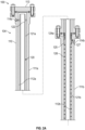
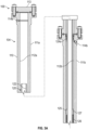
- FIGs. 2A-2B illustrate cross-sectional views of a well connect assembly 100 of the present disclosure that is hydraulically-actuated.
- Fig. 2A shows a majority of an injection module 104 of a well connect assembly 100
- Fig. 2B shows a remaining portion of the injection module 104 and shows a valve module 106 in the wellhead 10.
- the injection module 104 includes a housing 110 and an internal mandrel 120, which is movable in the housing 110.
- the housing 110 of the injection module 104 couples atop the wellhead 10, which can have a number of different components. These components may be existing on the wellhead 10 and would depend on the existing implementation.
- the wellhead 10 includes a casing hanger 20, a tubing hanger 30, a spool adapter 40, and a lower master gate valve 50. Other implementations may have different components for the wellhead 10 than shown here.
- the casing head 20 has the tubing hanger 30 landed in a landing bowl 24 of the head bore 22. Lock screws 25 can retain the tubing hanger 30 in place.
- the tubing hanger 30 can support a tubing string (not shown) in the well and may support capillary control lines 18b.
- the adapter 40 is attached to the casing hanger 20 and has an adapter bore 42 that communicates with the hanger bore 32.
- hot-tap modules 44 are attached to the adapter 40 to provide access to connector lines 18a that run from the adapter 40 to the tubing hanger 30. These lines 18a can communicate through passages in the tubing hanger 30 to the existing control lines 18b supported by the tubing hanger 30. Other implementations are possible.
- the lower gate valve 50 is attached to the adapter 40.
- the gate valve 50 includes a bonnet actuator 52 that can move a gate 56 inside the valve 50 relative to gate seals 54 to open or close fluid communication through the valve 50.
- the lower end of the injection housing 110 of the well connect assembly 100 is attached above the gate valve 50 in this example.
- the injection housing 110 can include an upper spool 111a that connects to a lower spool 111b and can include a top cap 113 to enclose the inside of the housing 110.
- the modular configuration facilitates assembly, but other configurations for the housing 110 can be used.
- the housing 110 includes an injection chamber 112a separated from a hydraulic chamber 112b by an annular seal 124a, which seals against the internal mandrel 120.
- the internal mandrel 120 is movably disposed in the housing 110 against the bias of a return spring 126 or other biasing element.
- the spring 126 is a compression spring disposed in the housing 110. An upper end of the spring 126 fit against a shoulder of a piston portion 125 of the mandrel 120, and a lower end of the spring 126 as shown in Fig. 2B fits against a shoulder in the housing 110.
- Other biasing arrangements can be used.
- the mandrel 120 defines a flow bore 122 therethrough from a proximal end to a distal end. Additionally, the mandrel 120 includes a first (upper) flow tube portion 121a at the proximal end and includes a second (lower) flow tube portion 121b at the opposite distal end. The piston portion 125 is disposed between the flow tube portions 121a-b and has an annular seal 127 that slideably seals in the housing 110.
- the housing 110 includes an insertion or injection port 114a for insertion or injection of media, chemicals, hydraulics, or the like into the injection chamber 112a.
- the housing 110 includes a hydraulic port 114b for introducing hydraulic fluid into the hydraulic chamber 112b.
- the annular seal 124a keeps the injection fluid in the injections chamber 112a separate from the hydraulic fluid in the hydraulic chamber 112b.
- the hydraulic chamber 112b is a variable volume defined between the annular seal 124a and the piston portion 125 with its seals 127. Increasing hydraulic pressure in the hydraulic chamber 112b applies force on the piston portion 125 to move the mandrel 120 down in the housing 110 against the bias of the spring 126. Reduction in the hydraulic pressure in the hydraulic chamber 112b and the return bias of the spring 126 can move the mandrel 120 to its retracted position up in the housing 110.
- the distal end of the mandrel 120 includes a stinger 130, which can have a check valve 140.
- the valve module 106 of the well connect assembly 100 includes a capillary hanger 150 and a valve 160.
- the capillary hanger 150 is installed in a backpressure valve (BPV) profile 34 of the tubing hanger 30.
- BPV backpressure valve
- an external thread profile 154 on the capillary hanger 150 can thread into the threaded BPV profile 34 of the tubing hanger 30.
- a seal ring 155 on the capillary hanger 150 can seal against the inner bore 32 of the hanger 30.
- the capillary hanger 150 supports a capillary line 102 using a connector 170.
- the valve 160 is disposed in the capillary hanger 150 and controls fluid communication with the capillary line 102.
- the valve 160 is a no-return valve, a check valve, a poppet valve, or the like that prevents fluid communication from downhole to uphole ( i.e. , prevents backpressure from the well) and that allows fluid communication from uphole to downhole ( i.e ., allows the fluid injection to pass to the capillary line 102).
- Figs. 4 and 6 discussed below shows details of the capillary hanger 150 and the check valve 160.
- Figs. 2A-2B the well connect assembly 100 is shown in an initial operational stage on the wellhead 10 before injection is performed.
- the gate valve 50 is closed, and the mandrel 120 is retracted to a retracted position in the housing 110. In this position, the stinger 130 on the distal end of the mandrel 120 is retracted from the gate 56 and seals 54 of the gate valve 50 so the gate valve 50 can function as normal.
- the well connect assembly 100 in Figs. 3A-3B is shown in a subsequent operational stage on the wellhead 10 for injection to be performed.
- the gate valve 50 is opened so that the opening in the gate 56 aligns with the gate seals 54, as shown in Fig. 3B .
- the check valve 140 on the stinger 130 can prevent well fluids from entering the bore 122 of the mandrel 120. Additionally, the check valve 160 on the capillary hanger 150 can prevent well fluids from entering above the tubing hanger 30.
- hydraulic pressure at the hydraulic port 114b pumps the retractable mandrel 120 down in the housing 110, through the open gate valve 50, and into the tubing hanger 30.
- the stinger 130 on the end of the mandrel 120 stings into the capillary hanger 150 and opens the check valve 160.
- Injection fluid e.g., chemicals, hydraulics, or the like
- the injected fluid can now pass through the mandrel's bore 122, through the open check valve 160, and through the capillary hanger 150 to be conveyed via the capillary line 102 further downhole.
- the mandrel 120 is moved so the mandrel's bore 122 is connected in fluid communication to the capillary line 102 supported in the wellhead 10.
- hydraulics drive down the mandrel 120 to make the connection.
- Other forms of actuation can drive the mandrel 120 down to make the connection.
- pneumatic actuation as briefly mentioned above can drive the mandrel 120 to make the connection.
- a mechanical form of actuation having a motor, screw rod, gears, etc. using electricity, hydraulics, pneumatics, or the like for power can be used to drive the mandrel 120.
- Hydraulic actuation may be preferred for most implementations because the well connect assembly 100 can operate similar to a safety valve. If hydraulic pressure is lost (e.g., the hydraulic manifold fails, power is lost, etc.), the return spring 126 can retract the mandrel 120 in a fail-safe to stop injection when the hydraulic pressure drops in the hydraulic chamber 112b.
- the hydraulic manifold (105) connected to the hydraulic port 114b can be tied into or can be part of other systems at the wellsite, such as a shut-down system, which is used to shut in the well by closing the gate valve 50. Should the shut-down system detect the need for shut in due to pressure measurements or the like, then the hydraulic manifold (105) can release hydraulic pressure in the chamber 112b so the manifold 120 retracts by operation of the spring 160, allowing the gate valve 50 to be shut.
- a lower annular seal 124b seals the annulus between the housing 110 and the lower flow tube portion 121b of the mandrel 120.
- This seal 124b can prevent well fluids from entering the second variable volume on the other side of the piston portion 125 where the spring 126 is located. Well pressure in this volume would act against the operation of the piston 125.
- a vent port 116 can allow this volume to be evacuated. Also, if feasible, the port 116 could be used to hydraulically raise the mandrel 120 by having hydraulic fluid injected into the second variable volume between the piston portion 125 and the lower annular seal 124b while venting the first variable volume from the hydraulic port 114b.
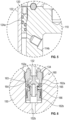
- Fig. 4 illustrates a detailed cross-sectional view of the stinger 130 and the capillary hanger 150.
- the stinger 130 is shown disposed on the distal end of the mandrel 120 and includes a mandrel check valve 140 for controlling fluid communication with the mandrel's bore 122.
- the capillary hanger 150 is installed in the BPV profile 34 of the tubing hanger 30 and includes a hanger check valve 160.
- the stinger 130 is stung into a receptacle 152a of the capillary hanger 150, and a distal tip 134 of the stinger 130 engages the check valve 160 of the capillary hanger 140.
- Injected fluid from the mandrel's bore 122 can open the mandrel check valve 140, can pass into the stinger passage 132, can pass through the opened hanger check valve 160, and can pass into the hanger passage 152b so the injected fluid can pass into the connector 170 of the capillary line (not shown).
- the mandrel's check valve 140 will close, preventing back flow of fluids. Should the stinger 130 be unstung from the hanger's check valve 140 due to a reduction in hydraulic pressure against the mandrel 120, the hanger's check valve 140 will close, preventing back flow of fluids.
- Fig. 5 illustrates a detailed cross-sectional view of the annular seal 124a separating the chambers 112a-b of the injection housing 110 and sealing against the outer surface of the mandrel 120.
- the annular seal 124a can be a gland seal thread into the mandrel's housing 110, and the annular seal 124a can have inner and outer annular seal elements for sealably engaging between the housing 110 and the mandrel 120.
- the inner seal elements of the annular seal 124a preferably allow for sliding sealing with the surface of the mandrel 120, which is movable in the housing 110.
- Fig. 6 illustrates a detailed cross-sectional view of the check valve 160 for the capillary hanger 150.
- the check valve 160 in this example is a poppet valve, but other types of valves can be used.
- a lower retainer 162b fits into the receptacle 152a of the hanger 150, and an upper retainer 162a affixes in the receptacle 152a to hold a poppet 164 therein.
- a spring 166 biases the poppet 164 toward a seat 163 in the retainer 162a to seal off fluid communication from the hanger passage 152b up through the check valve 160.
- the poppet 164 unseats from the seat 163 and exposes bypass ports 165 in the poppet 164. Fluid can now communicate through the open check valve 160.
- the check valve (140) for the stinger 130 may be comparably configured.
- the well connect assembly 100 can be used with wellheads of different configurations.
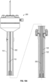
- Fig. 7 illustrates the well connect assembly 100 installed on another wellhead implementation.
- the wellhead 10 is a production tree that includes a tubing head adapter 40 connected to a tubing head 20.
- Lower and upper master valves 50a-b connect above the adapter 40, and a studded cross 60 mounts to the top of the upper master gate valve 50b.
- a flow line gate valve 62 and a kill line gate valve 64 connect to opposite sides of the studded cross 60, and the gate valves 62 and 64 connect to additional components ( e.g. , piping, chokes, etc.).
- the master gate valves 50a-b can be opened and closed to control flow for the wellbore.
- the flow line and kill line gate valves 62, 64 are used to control the flow line and kill lines (not shown).
- the top cap 66 can be removed to provide access to the wellbore for various operations.
- a capillary line (not shown) connected the valve module 106 can be installed through the wellhead 10 using standard procedures, and the valve module 106 can be installed in a tubing hanger 30 in the casing hanger 20.
- the well connect assembly 100 can then connect to the top of the studded cross 60 in place of the top cap 66.
- the well connect assembly 100 can operate as before. In the retracted position, the mandrel 120 is retracted from the gate valves 50a-b. In the extended position, the mandrel 120 is extended through the open gate valves 50a-b to the valve module 106 (having the capillary hanger 150 and check valve 160) installed in the tubing hanger 30 of the wellhead 10.
- the well connect assembly 100 of the present disclosure may be hydraulically actuated, but other forms of actuation can drive the mandrel 120 down to make the connection.
- a mechanical form of actuation having a motor, screw rod, gears, etc. could be used to drive the mandrel 120.
- Fig. 8 is an example of one such mechanical arrangement for an actuation device 107'.
- the rest of the components of the injection module 104 can be the same as before.
- the housing 110 includes an opening, pocket, enclosure, etc. for a pinion gear 210 exposed in the lower chamber 112b.
- the mandrel 120 includes a rack gear 220 along a portion of its length for engagement with the pinion gear 210.
- a motor (not shown) for the actuator device 107' which can be hydraulic, pneumatic, electric, or the like, can rotate the pinion gear 210 to lower the mandrel 120 to extend the mandrel 120 to its extended condition to make the fluid connection.
- the motor for the actuator device 107' can reverse the rotation to raise the mandrel 120 to its retracted condition, or a torsion spring (not shown) on the pinion gear 210 can reverse the rotation of the pinion gear 210 upon release of the motor or a clutch arrangement.
- a rotary seal 212 can be provided for the pinion gear 210
- a glandular seal 124b can be used between the housing 100 and the mandrel 120 to seal the rack gear 220.
- Fig. 9 is an example of another mechanical arrangement of an actuation device 107' in the form of a worm gear screw jack.
- the housing 110 includes an opening, pocket, enclosure, etc. for a worm 230 engaged with a worm gear 240 exposed in the lower chamber 112b.
- the mandrel 120 includes a screw gear 250 along a portion of its length for engagement with a threaded interior of the worm gear 240.
- a motor (not shown) for the actuator device 107' which can be hydraulic, pneumatic, electric or the like, can rotate the worm 230, which rotates the worm gear 240 to translate the mandrel 120 to extend the mandrel 120 to its extended condition to make the fluid connection.
- the motor for the actuator device 107' can reverse the rotation to raise the mandrel 120 to its retracted condition, or a torsion spring (not shown) on the worm 230 can reverse the rotation of the worm gear 240 upon release of the motor or a clutch arrangement.
- Appropriate sealing is used for the housing 10 to seal the worm 230 and the screw gear 250.
- a rotary seal 212 can be provided for the worm 230, and a glandular seal 124b can be used between the housing 100 and the mandrel 120 to seal the screw gear 230.
- bearings, shafts, sleeves, and other necessary features are not shown in Figs. 8 and 9 . These and other forms of mechanical configurations can be used.
- the well connect assembly 100 can be used for communicating hydraulics and chemicals through the wellhead 10, but other forms of media can be communicated by the well connect assembly 100 through the wellhead 10.
- other forms of media can be communicated by the well connect assembly 100 through the wellhead 10.
- physical connections for electrical and optical communications can also be achieved using the disclosed assembly 100.
- Figs. 10A-10B show an example of the well connect assembly 100 providing a connection for electrical and optical communications according to the present disclosure.
- the assembly 100 includes components similar to other embodiments discussed above so the same reference numerals are used for similar components.
- the housing 110 mounted on the wellhead 10 includes an insertion port for inserting the media, namely an insertion assembly 200 for inserting a capillary line, electrical cable, fiber optics cable, or other type of media line into the housing 110.
- the insertion assembly 200 can include a stuffing box, packing glands, hangers, couplings, and other components used in the art.
- the media lines 202/204 can include a cable used for a deployed electric submersible pump (ESP) system. In another example, the media lines 202/204 can be used to run fiber optic lines downhole to a thru-tubing fibre optic reservoir monitoring system or the like.
- ESP electric submersible pump
- a media line 202 can be inserted through the insertion assembly 200 and can be run down through the mandrel 120 that is stung into the tubing hanger 130. If a back-pressure valve (not shown) is present in the tubing hanger 30, the media line 202 can pass through and open the valve. From there, the media line 202 can be run further downhole from the wellhead 10. Should the mandrel 120 be retracted, however, the media line 202 would remain passing through the gate valve 50. The media line 202 would need to be retrieved or broken for the gate valve 50 to close.
- a media line 202 can be inserted through the insertion assembly 200 to make a connection to another media line 204 supported on a hanger 151 in the wellhead 10.
- a coupling 203 for example, on the end of the media line 202 can make a connection to another coupling 205 for the media line 204 supported on the hanger 151.
- the coupling 203 may be supported at the distal end or stinger of the mandrel 120 so the connection can be made as the mandrel 120 is moved and stung into the hanger 151.
- the mandrel 120 can be driven as before so that the distal end stings into the hanger 151, as shown in Fig. 10B .
- This stinging can open a one-way valve (not shown), such as a flapper valve or other type of valve, on the hanger 151 if present.
- the media line 202 from the well connection assembly 100 can thereby connect with the media line 204 in the well through the connection of the couplings 203, 205.
- the media line 202 passed through the stuffing box 200 can be unconnected from the hanger 151 at the couplings 203, 205, and the media line 202 can be moved up through the gate valve 50 with the retraction of the mandrel 120.
- Figs. 11A-11C illustrate schematic views for mandrels 120 of the present disclosure.
- the mandrel 120 can be a unitary component having an upper flow tube portion 121a, a piston portion 125, and a lower flow tube portion 121b.
- the mandrel 120 can be comprised of two or more components, facilitating assembly.
- the upper flow tube portion 121a and the piston portion 125 may be a unitary component with the lower flow tube portion 121b being attached (e.g., threaded) thereto.
- An opposite arrangement can be used, or all three components 121a-b, 125 can be separate elements.
- Fig. 11C illustrates a schematic view for a telescopic mandrel 120 of the present disclosure in which the mandrel 120 is comprised of two or more telescoping components.
- the lower tube portion 121b' and the piston portion 125 can be a unitary component, while the upper tube portion 121a' is a telescoping component disposed in the lower tube portion 121b'.
- the telescoping components use appropriate seals (not shown) and catches (not shown) therebetween.
- An edge of the upper tube portion 121a' can be in contact with a shoulder 115 or the like of the assembly's housing.
- Movement downward by hydraulic pressure against the piston portion 125 can then stroke the lower tube portion 121b' down along the length of the upper tube portion 121a' against the bias of the spring 126.
- the upper seal 124a maintains a seal with the upper tube portion 121a';
- the lower seal 124b maintains a seal with the lower tube portion 121b'; and
- an intermediate seal 124c seals between the tube portions 121a', 121b'.
Landscapes
- Life Sciences & Earth Sciences (AREA)
- Engineering & Computer Science (AREA)
- Geology (AREA)
- Mining & Mineral Resources (AREA)
- Physics & Mathematics (AREA)
- Environmental & Geological Engineering (AREA)
- Fluid Mechanics (AREA)
- General Life Sciences & Earth Sciences (AREA)
- Geochemistry & Mineralogy (AREA)
- Sliding Valves (AREA)
- Consolidation Of Soil By Introduction Of Solidifying Substances Into Soil (AREA)
- Catching Or Destruction (AREA)
Description
- At times, well operations require capillary lines to be run downhole from an existing wellhead into a live well. In some situations, a capillary line needs to be run downhole extending from the wellhead so chemical injection can be performed downhole. In other situations, a hydraulically-actuated tool needs to be run downhole and needs to be controlled by a new control line extending from the wellhead. For example, an existing safety valve installed downhole may stop functioning because an existing control line to the safety valve has become blocked or damaged. When the hydraulic pressure is lost, the existing safety valve closes so that production from the well stops. Operators then need to run and install a surface-controlled subsurface safety valve and an alternate control line through the wellhead and into the production tubing so production can be restored.
- These and other situations require operators to extend a capillary line from the wellhead and to communicate control fluids, chemicals, or the like into the capillary line. Doing this for a live well in an effective way can be challenging. To that end, the subject matter of the present disclosure is directed to overcoming, or at least reducing the effects of, one or more of the problems set forth above.
-
US 2004/079532 discloses a tubular support system with a bowl and a hanger, the bowl for supporting at least one tubular member and including a body with at least one access port for accessing a fluid channel opening of the hanger positioned within the bowl; the hanger for connection to a tubular member and having at least one fluid channel through it from a bottom surface to an outer surface so that one or more control lines attached to a supported tubular (pipe, casing, riser, tubing) can be placed in fluid communication with the at least one fluid channel, and, via the at least one access port, the at least one fluid channel can be placed in fluid communication with other apparatus, e.g., a surface control unit. - In one aspect of the present disclosure there is provided an assembly according to
claim 1 and a method according to claim 15. An assembly disclosed herein is for communicating a media through a wellhead to a media line in a well. The wellhead has at least one gate valve mounted above the wellhead. The assembly comprises a module, a housing, and a mandrel. The module configured to install in the wellhead and is configured to support the media line extending therefrom. The housing is configured to mount above the at least one gate valve and has an insertion port for the media. The mandrel is disposed in the housing and has a proximal end and a distal end. The mandrel defines a bore therethrough from the proximal end to the distal end for the media. The mandrel is movable between a retracted condition and an extended condition. The mandrel in the retracted condition has the distal end retracted from the at least one gate valve. The mandrel in the extended condition is extended through the at least one gate valve, has the distal end engaged with the module, and is configured to communicate the media with the media line. - The module can comprise a hanger configured to support the media line, and the hanger can have an external thread profile configured to install in the wellhead.
- The module can comprises a valve being actuatable at least from a closed condition to an opened condition. The valve in the closed condition can be configured to prevent fluid communication through the valve module, while the valve in the opened condition can be configured to allow fluid communication through the valve. The distal end of the mandrel in the extended condition can be configured to actuate the valve from the closed condition to the open condition.
- The valve can comprise: a seat affixed in an internal passage of the hanger; a poppet movable in the internal passage between seated and unseated conditions relative to the seat, a tip of the poppet being engageable by the distal end of the mandrel; and a biasing element in the internal passage biasing the poppet to the seated condition.
- The mandrel can comprise a valve disposed in the bore, the valve being movable between a closed condition and an opened condition in response to a pressure differential thereacross, the valve in the closed condition being configured to prevent fluid communication through the valve, the valve in the opened condition being configured to allow fluid communication through the valve.
- The assembly can comprise a biasing element disposed in the housing and biasing the mandrel to the retracted condition.
- The assembly can comprise a mechanism being configured to move the mandrel relative to the housing. For example, the mechanism can comprise: a first gear associated with the housing and being movable; and a second gear associated with the mandrel and being engaged with the first gear. In another example, the mechanism can comprise a hydraulic actuator being configured to move the mandrel with hydraulic pressure communicated to a portion of the housing.
- The assembly can be operated by hydraulic pressure. The housing can comprise: a first chamber having the insertion port for the media, and a second chamber having a hydraulic port for the hydraulic pressure. The mandrel can be movable between the retracted condition and the extended condition in response to the hydraulic pressure in the second chamber.
- The mandrel can comprise a piston portion sealed in the housing so the mandrel can be movable in the housing in response to the hydraulic pressure in the housing applied against the piston portion. In this example, the housing can comprise a first annular seal disposed in the housing and sealing an annulus between the housing and the mandrel. The first annular seal can separate the housing into the first and second chambers. The second chamber has a first variable volume defined between the first annular seal and the piston portion. In this example, the housing can also comprise a second annular seal disposed in the housing and sealing the annulus between the housing and the mandrel. The distal end of the mandrel in the retracted and extended conditions can be disposed beyond the second annular seal.
- In the assembly, the bore of the mandrel in the extended condition can be configured to communicate: hydraulics for the media from the insertion port to a capillary line for the media line supported by the module; an eclectic cable for the media from the insertion port to another electric cable for the media line supported by the module; or an optical cable for the media from the insertion port to another optical cable for the media line supported by the module.
- An assembly disclosed herein is operated by hydraulic pressure for fluid injection through a wellhead to a capillary line. The wellhead has at least one gate valve mounted above the wellhead. The assembly comprises: a valve module, a housing, and a mandrel.
- The valve module is configured to install in the wellhead and is configured to support the capillary line extending therefrom. The valve module is actuatable from a closed condition to an opened condition. The valve module in the closed condition is configured to prevent fluid communication through the valve module, while the valve module in the opened condition is configured to allow fluid communication through the valve module;
- The housing is configured to mount above the at least one gate valve. The housing comprises: a first chamber having an injection port for the fluid injection, and a second chamber having a hydraulic port for the hydraulic pressure. The mandrel is disposed in the housing and defines a bore therethrough from a proximal end to a distal end. The proximal end is exposed in the first chamber. The mandrel is movable between a retracted condition and an extended condition in response to the hydraulic pressure in the second chamber. The mandrel in the retracted condition has the distal end retracted from the gate valve. The distal end of the mandrel in the extended condition is extended through the at least one gate valve and is configured to actuate the valve module from the closed condition to the open condition.
- A method is disclosed herein for communicating a media through a wellhead to a communication line in a well. The wellhead has at least one gate valve mounted thereabove. The method comprises: supporting the communication line with a module; installing the communication line and the module through a top of the wellhead; mounting a housing above the at least one gate valve of the wellhead; moving a mandrel disposed in the housing from a retracted condition and an extended condition, a distal end of the mandrel in the retraced condition being retracted from the at least one gate valve; engaging the distal end of the mandrel in the extended condition through the at least one gate valve to the module; and communicating the media from an insertion port in the housing, through a bore of the mandrel, and to the communication line supported by the module.
- For example, the method can be used for fluid injection through a wellhead to a capillary line in a well. This method can comprise supporting the capillary line with a capillary hanger; installing the capillary hanger in the wellhead; mounting a housing above the at least one gate valve; moving a mandrel disposed in the housing from a retracted condition and an extended condition, a distal end of the mandrel in the retraced condition being retracted from the at least one gate valve; opening a first valve in the capillary hanger with the distal end of the mandrel in the extended condition being extended through the at least one gate valve to the first valve; and communicating the fluid injection from an injection port in the housing, through a bore of the mandrel, through the open first valve, and into the capillary line.
- The foregoing summary is not intended to summarize each potential embodiment or every aspect of the present disclosure.
-
-
Fig. 1 illustrates a schematic view of a wellhead supporting capillary lines in a well. -
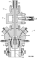
Figs. 2A-2B illustrate a cross-sectional view of a well connect assembly of the present disclosure in an initial operational stage. -
Figs. 3A-3B illustrate a cross-sectional view of the well connect assembly of the present disclosure in a subsequent operational stage. -
Fig. 4 illustrates a detailed cross-sectional view of a stinger engaged with a capillary hanger of the well connect assembly. -
Fig. 5 illustrates a detailed cross-sectional view of an annular seal of the well connect assembly. -
Fig. 6 illustrates a detailed cross-sectional view of a valve for the well connect assembly. -
Fig. 7 illustrates the well connect assembly installed on another wellhead implementation. -
Fig. 8 illustrates a portion of the well connect assembly having an alternative actuator arrangement. -
Fig. 9 illustrates a portion of the well connect assembly having another alternative actuator arrangement. -
Figs. 10A-10B illustrate a cross-sectional view of another well connect assembly of the present disclosure in an operational stage. -
Figs. 11A-11C illustrate schematic views for mandrels of the present disclosure. -
Fig. 1 illustrates a schematic view of awellhead 10 for a well 12. Thewellhead 10 includes acasing head 20 having atubing hanger 30 supported therein. As shown, thetubing hanger 30 can support atubing string 14 in the well 12 and may support some existing capillary lines 18. - Typically, above the
casing head 20, thewellhead 10 has one ormore master valves 50, which can be gate valves, to open and close fluid communication of the well 12 for thewellhead 10. Above these, thewellhead 10 may have a flow tee (not shown) with a flow line gate valve (not shown) and a kill line gate valve (not shown) connected to piping and additional components. - During operations, a media line, such as a capillary line, cable, or the like for the well 12 may need to be run downhole in the
well 12. For example, an existingcapillary line 18 may become clogged, broken, or otherwise become inoperable and may require replacement. In this case, operators may need to run anew capillary line 102 in the well. Alternatively, anew media line 102 may need to be deployed from surface for a particular purpose, such as to connect to downhole equipment or to inject chemicals. In such circumstances, operators will need to run thenew media line 102 downhole though thewellhead 10 that is already assembled. - The present example shows several lines run downhole in the well. These lines can be used for a number of purposes. Some of the
lines 18 may be existing capillary lines run in thewell 12. The existinglines 18 would typically be suspended from an existingtubing hanger 30 inside thewellhead 10. For example, one or morecapillary lines 18 can be used as a control line for surface-controlledsubsurface equipment 16, such as a hydraulically-actuated downhole tool, a surface-controlled subsurface safety valve (SCSSV), or the like, disposed downhole in thewell 12. - Some of the
media lines 102, 102' may be newly installed media lines run in the well 12, which are run through the existingmaster valve 50 and other components of thewellhead 10. If an existingcapillary line 18 becomes inoperable, for example, a new media line 102' in the form of a hydraulic control line may need to be run downhole from thewellhead 10. In another example, anew media line 102 can be used as an injection line for injecting chemicals to downhole into thewell 12. Chemicals from achemical injection manifold 105 are injected down thecapillary line 102 to achemical injection valve 103 in the well. The chemical injection can be used to reduce corrosion in the well, to reduce buildup of wax and scale in the well, to enhance production, and the like. The media lines 18, 102, 102' for thewellhead 10 can be used for these and other purposes known in the art. - Simply running a media line from a top cap of the
wellhead 10 through the gate valve(s) 50 and other components of thewellhead 10 is not suitable in most cases. To run a media line on the existingwellhead 10, operators would typically need to add a new tubing spool to thewellhead 10, may need to modify or change out the lowermaster gate valve 50 on thewellhead 10, may need to perform a hot-tap in thewellhead 10, or may need to conduct some other remedial action, which can be cumbersome and complicated. Put simply, disassembling, moving, or changing parts of the existingwellhead 10 may not be desired in many instances. - In contrast to the typical remedial actions, a well connect
assembly 100 of the present disclosure is instead used on thewellhead 10. Thewell connect assembly 100 installs on thewellhead 10 so theassembly 100 can support amedia line 102 or 102' and can allow operators to perform fluid injection, communicate hydraulics, make electrical or optical connections, or perform other appropriate operation. Themedia line 102 or 102' may be newly deployed in the well or may be already installed. For example, the well connectassembly 100 can support a capillary line for themedia line 102 so operators can perform chemical injection. In another example, the well connectassembly 100 can support a hydraulic control line for the media line 102' so hydraulic communication can be made tosubsurface equipment 16. In yet another example, the well connectassembly 100 can support an electric or optical cable for the media line 102' so electric or optical communication can be made tosubsurface equipment 16. Examples that follow will primarily describe an arrangement in which the well connectassembly 100 supports a capillary line for themedia line 102 so operators can perform chemical injection. - As briefly shown in
Fig. 1 , the well connectassembly 100 includes aninjection module 104 and avalve module 106. Thevalve module 106 supports thecapillary line 102 and is installed in thewellhead 10 below the gate valve(s) 50. For example, thevalve module 106 can install in thetubing hanger 30 of thewellhead 10 in an operation similar to that used to install a backpressure valve in atubing hanger 30. Suitable equipment, such as a running tool, polished rod, and the like can be used to install thevalve module 106. - As shown in
Fig. 1 , thewellhead 10 has a lowermaster gate valve 50 installed on thecasing head 20, and theinjection module 104 mounts above themaster gate valve 50 on thewellhead 10. If an upper master valve (not shown), a flow tee (not shown), and the like are present, these components can remain on thewellhead 10, and theinjection module 104 is mounted on top of thewellhead 10 at the top cap. - With the
assembly 100 installed, anactuation device 107 actuates theassembly 100. For example, theactuation device 107 can be a hydraulic (or pneumatic manifold that communicates hydraulics (or pneumatics) to ahydraulic port 114b on theinjection module 104 to actuate theassembly 100. While theassembly 100 is actuated, aninjection manifold 105 injects chemicals, hydraulics, or other intended fluid into aninjection port 114a of theinjection module 104, which can communicate down theassembly 100, through thegate valve 50, and to thevalve module 106 installed in thetubing hanger 30. Thevalve module 106 can then communication the fluid injection further through the supportedcapillary line 102 in thewell 12. - As can generally be seen, the well connect
assembly 100 allows for a fluid connection to be made at surface to downhole in a well 12 without the need to add a tubing spool to thewellhead 10, without the need to convert themaster gate valve 50, and without the need to perform other cumbersome or time-consuming operations. All the while, thewellhead 10 is protected from surface backpressure from the well 12, and the well connectassembly 100 can be deactivated to maintain well integrity. - Having a general understanding of the well connect
assembly 100, discussion turns toFigs. 2A-2B , which illustrate cross-sectional views of a well connectassembly 100 of the present disclosure that is hydraulically-actuated. -
Fig. 2A shows a majority of aninjection module 104 of a well connectassembly 100, whileFig. 2B shows a remaining portion of theinjection module 104 and shows avalve module 106 in thewellhead 10. As shown inFig. 2A , theinjection module 104 includes ahousing 110 and aninternal mandrel 120, which is movable in thehousing 110. - As shown in
Fig. 2B , thehousing 110 of theinjection module 104 couples atop thewellhead 10, which can have a number of different components. These components may be existing on thewellhead 10 and would depend on the existing implementation. Here, thewellhead 10 includes acasing hanger 20, atubing hanger 30, aspool adapter 40, and a lowermaster gate valve 50. Other implementations may have different components for thewellhead 10 than shown here. - The
casing head 20 has thetubing hanger 30 landed in alanding bowl 24 of the head bore 22. Lock screws 25 can retain thetubing hanger 30 in place. For its part, thetubing hanger 30 can support a tubing string (not shown) in the well and may supportcapillary control lines 18b. - The
adapter 40 is attached to thecasing hanger 20 and has an adapter bore 42 that communicates with the hanger bore 32. In this example, hot-tap modules 44 are attached to theadapter 40 to provide access toconnector lines 18a that run from theadapter 40 to thetubing hanger 30. Theselines 18a can communicate through passages in thetubing hanger 30 to the existingcontrol lines 18b supported by thetubing hanger 30. Other implementations are possible. - The
lower gate valve 50 is attached to theadapter 40. As is typical, thegate valve 50 includes abonnet actuator 52 that can move agate 56 inside thevalve 50 relative to gate seals 54 to open or close fluid communication through thevalve 50. As shown inFig. 2B , the lower end of theinjection housing 110 of the well connectassembly 100 is attached above thegate valve 50 in this example. - Returning to
Fig. 2A , theinjection housing 110 can include anupper spool 111a that connects to alower spool 111b and can include atop cap 113 to enclose the inside of thehousing 110. The modular configuration facilitates assembly, but other configurations for thehousing 110 can be used. - The
housing 110 includes aninjection chamber 112a separated from ahydraulic chamber 112b by anannular seal 124a, which seals against theinternal mandrel 120. (Fig. 5 discussed below shows details of theannular seal 124a.) Theinternal mandrel 120 is movably disposed in thehousing 110 against the bias of areturn spring 126 or other biasing element. For example, thespring 126 is a compression spring disposed in thehousing 110. An upper end of thespring 126 fit against a shoulder of apiston portion 125 of themandrel 120, and a lower end of thespring 126 as shown inFig. 2B fits against a shoulder in thehousing 110. Other biasing arrangements can be used. - As best shown in
Fig. 2A , themandrel 120 defines aflow bore 122 therethrough from a proximal end to a distal end. Additionally, themandrel 120 includes a first (upper) flowtube portion 121a at the proximal end and includes a second (lower)flow tube portion 121b at the opposite distal end. Thepiston portion 125 is disposed between theflow tube portions 121a-b and has anannular seal 127 that slideably seals in thehousing 110. - The
housing 110 includes an insertion orinjection port 114a for insertion or injection of media, chemicals, hydraulics, or the like into theinjection chamber 112a. Likewise, thehousing 110 includes ahydraulic port 114b for introducing hydraulic fluid into thehydraulic chamber 112b. Meanwhile, theannular seal 124a keeps the injection fluid in theinjections chamber 112a separate from the hydraulic fluid in thehydraulic chamber 112b. - The
hydraulic chamber 112b is a variable volume defined between theannular seal 124a and thepiston portion 125 with itsseals 127. Increasing hydraulic pressure in thehydraulic chamber 112b applies force on thepiston portion 125 to move themandrel 120 down in thehousing 110 against the bias of thespring 126. Reduction in the hydraulic pressure in thehydraulic chamber 112b and the return bias of thespring 126 can move themandrel 120 to its retracted position up in thehousing 110. - As shown in
Fig. 2B , the distal end of themandrel 120 includes astinger 130, which can have acheck valve 140. As also shown inFig. 2B , thevalve module 106 of the well connectassembly 100 includes acapillary hanger 150 and avalve 160. Thecapillary hanger 150 is installed in a backpressure valve (BPV)profile 34 of thetubing hanger 30. For example, anexternal thread profile 154 on thecapillary hanger 150 can thread into the threadedBPV profile 34 of thetubing hanger 30. A seal ring 155 on thecapillary hanger 150 can seal against theinner bore 32 of thehanger 30. - The
capillary hanger 150 supports acapillary line 102 using aconnector 170. Thevalve 160 is disposed in thecapillary hanger 150 and controls fluid communication with thecapillary line 102. In particular, thevalve 160 is a no-return valve, a check valve, a poppet valve, or the like that prevents fluid communication from downhole to uphole (i.e., prevents backpressure from the well) and that allows fluid communication from uphole to downhole (i.e., allows the fluid injection to pass to the capillary line 102). (Figs. 4 and6 discussed below shows details of thecapillary hanger 150 and thecheck valve 160.) - In
Figs. 2A-2B , the well connectassembly 100 is shown in an initial operational stage on thewellhead 10 before injection is performed. Thegate valve 50 is closed, and themandrel 120 is retracted to a retracted position in thehousing 110. In this position, thestinger 130 on the distal end of themandrel 120 is retracted from thegate 56 and seals 54 of thegate valve 50 so thegate valve 50 can function as normal. In contrast, the well connectassembly 100 inFigs. 3A-3B is shown in a subsequent operational stage on thewellhead 10 for injection to be performed. - To initiate injection operations, the
gate valve 50 is opened so that the opening in thegate 56 aligns with the gate seals 54, as shown inFig. 3B . Thecheck valve 140 on thestinger 130 can prevent well fluids from entering thebore 122 of themandrel 120. Additionally, thecheck valve 160 on thecapillary hanger 150 can prevent well fluids from entering above thetubing hanger 30. - As shown in
Figs. 3A-3B , hydraulic pressure at thehydraulic port 114b pumps theretractable mandrel 120 down in thehousing 110, through theopen gate valve 50, and into thetubing hanger 30. Thestinger 130 on the end of themandrel 120 stings into thecapillary hanger 150 and opens thecheck valve 160. Injection fluid (e.g., chemicals, hydraulics, or the like) for the fluid injection are pumped into theinjection chamber 112a from theinjection port 114a. The injected fluid can now pass through the mandrel'sbore 122, through theopen check valve 160, and through thecapillary hanger 150 to be conveyed via thecapillary line 102 further downhole. - For the injection operation, the
mandrel 120 is moved so the mandrel'sbore 122 is connected in fluid communication to thecapillary line 102 supported in thewellhead 10. In the current examples, hydraulics drive down themandrel 120 to make the connection. Other forms of actuation can drive themandrel 120 down to make the connection. For example, pneumatic actuation as briefly mentioned above can drive themandrel 120 to make the connection. In other example, a mechanical form of actuation having a motor, screw rod, gears, etc. using electricity, hydraulics, pneumatics, or the like for power can be used to drive themandrel 120. - Hydraulic actuation may be preferred for most implementations because the well connect
assembly 100 can operate similar to a safety valve. If hydraulic pressure is lost (e.g., the hydraulic manifold fails, power is lost, etc.), thereturn spring 126 can retract themandrel 120 in a fail-safe to stop injection when the hydraulic pressure drops in thehydraulic chamber 112b. The hydraulic manifold (105) connected to thehydraulic port 114b can be tied into or can be part of other systems at the wellsite, such as a shut-down system, which is used to shut in the well by closing thegate valve 50. Should the shut-down system detect the need for shut in due to pressure measurements or the like, then the hydraulic manifold (105) can release hydraulic pressure in thechamber 112b so the manifold 120 retracts by operation of thespring 160, allowing thegate valve 50 to be shut. - As further shown in
Fig. 3B , a lowerannular seal 124b seals the annulus between thehousing 110 and the lowerflow tube portion 121b of themandrel 120. Thisseal 124b can prevent well fluids from entering the second variable volume on the other side of thepiston portion 125 where thespring 126 is located. Well pressure in this volume would act against the operation of thepiston 125. Avent port 116 can allow this volume to be evacuated. Also, if feasible, theport 116 could be used to hydraulically raise themandrel 120 by having hydraulic fluid injected into the second variable volume between thepiston portion 125 and the lowerannular seal 124b while venting the first variable volume from thehydraulic port 114b. -
Fig. 4 illustrates a detailed cross-sectional view of thestinger 130 and thecapillary hanger 150. Thestinger 130 is shown disposed on the distal end of themandrel 120 and includes amandrel check valve 140 for controlling fluid communication with the mandrel'sbore 122. Thecapillary hanger 150 is installed in theBPV profile 34 of thetubing hanger 30 and includes ahanger check valve 160. Thestinger 130 is stung into areceptacle 152a of thecapillary hanger 150, and adistal tip 134 of thestinger 130 engages thecheck valve 160 of thecapillary hanger 140. Injected fluid from the mandrel'sbore 122 can open themandrel check valve 140, can pass into thestinger passage 132, can pass through the openedhanger check valve 160, and can pass into thehanger passage 152b so the injected fluid can pass into theconnector 170 of the capillary line (not shown). - Should the injection pressure in the mandrel's
bore 120 fall below a predetermined level, the mandrel'scheck valve 140 will close, preventing back flow of fluids. Should thestinger 130 be unstung from the hanger'scheck valve 140 due to a reduction in hydraulic pressure against themandrel 120, the hanger'scheck valve 140 will close, preventing back flow of fluids. -
Fig. 5 illustrates a detailed cross-sectional view of theannular seal 124a separating thechambers 112a-b of theinjection housing 110 and sealing against the outer surface of themandrel 120. Theannular seal 124a can be a gland seal thread into the mandrel'shousing 110, and theannular seal 124a can have inner and outer annular seal elements for sealably engaging between thehousing 110 and themandrel 120. The inner seal elements of theannular seal 124a preferably allow for sliding sealing with the surface of themandrel 120, which is movable in thehousing 110. -
Fig. 6 illustrates a detailed cross-sectional view of thecheck valve 160 for thecapillary hanger 150. Thecheck valve 160 in this example is a poppet valve, but other types of valves can be used. Alower retainer 162b fits into thereceptacle 152a of thehanger 150, and anupper retainer 162a affixes in thereceptacle 152a to hold apoppet 164 therein. Aspring 166 biases thepoppet 164 toward aseat 163 in theretainer 162a to seal off fluid communication from thehanger passage 152b up through thecheck valve 160. When thedistal tip 134 of thestinger 130 pushes against thepoppet 164, thepoppet 164 unseats from theseat 163 and exposesbypass ports 165 in thepoppet 164. Fluid can now communicate through theopen check valve 160. Although not shown here, the check valve (140) for thestinger 130 may be comparably configured. - As noted above, the well connect
assembly 100 can be used with wellheads of different configurations.Fig. 7 illustrates the well connectassembly 100 installed on another wellhead implementation. Here, thewellhead 10 is a production tree that includes atubing head adapter 40 connected to atubing head 20. Lower andupper master valves 50a-b connect above theadapter 40, and astudded cross 60 mounts to the top of the uppermaster gate valve 50b. As is typical, a flowline gate valve 62 and a killline gate valve 64 connect to opposite sides of thestudded cross 60, and thegate valves - The
master gate valves 50a-b can be opened and closed to control flow for the wellbore. The flow line and killline gate valves top cap 66 can be removed to provide access to the wellbore for various operations. For example, a capillary line (not shown) connected thevalve module 106 can be installed through thewellhead 10 using standard procedures, and thevalve module 106 can be installed in atubing hanger 30 in thecasing hanger 20. Thewell connect assembly 100 can then connect to the top of thestudded cross 60 in place of thetop cap 66. - The
well connect assembly 100 can operate as before. In the retracted position, themandrel 120 is retracted from thegate valves 50a-b. In the extended position, themandrel 120 is extended through theopen gate valves 50a-b to the valve module 106 (having thecapillary hanger 150 and check valve 160) installed in thetubing hanger 30 of thewellhead 10. - As noted above, the well connect
assembly 100 of the present disclosure may be hydraulically actuated, but other forms of actuation can drive themandrel 120 down to make the connection. For example, a mechanical form of actuation having a motor, screw rod, gears, etc. could be used to drive themandrel 120.Fig. 8 is an example of one such mechanical arrangement for anactuation device 107'. The rest of the components of theinjection module 104 can be the same as before. - The
housing 110 includes an opening, pocket, enclosure, etc. for apinion gear 210 exposed in thelower chamber 112b. Themandrel 120 includes arack gear 220 along a portion of its length for engagement with thepinion gear 210. A motor (not shown) for theactuator device 107', which can be hydraulic, pneumatic, electric, or the like, can rotate thepinion gear 210 to lower themandrel 120 to extend themandrel 120 to its extended condition to make the fluid connection. The motor for theactuator device 107' can reverse the rotation to raise themandrel 120 to its retracted condition, or a torsion spring (not shown) on thepinion gear 210 can reverse the rotation of thepinion gear 210 upon release of the motor or a clutch arrangement. Appropriate sealing is used for thehousing 110 to seal thepinion gear 210 and therack gear 220. For example, arotary seal 212 can be provided for thepinion gear 210, and aglandular seal 124b can be used between thehousing 100 and themandrel 120 to seal therack gear 220. -
Fig. 9 is an example of another mechanical arrangement of anactuation device 107' in the form of a worm gear screw jack. Thehousing 110 includes an opening, pocket, enclosure, etc. for aworm 230 engaged with aworm gear 240 exposed in thelower chamber 112b. Themandrel 120 includes ascrew gear 250 along a portion of its length for engagement with a threaded interior of theworm gear 240. A motor (not shown) for theactuator device 107', which can be hydraulic, pneumatic, electric or the like, can rotate theworm 230, which rotates theworm gear 240 to translate themandrel 120 to extend themandrel 120 to its extended condition to make the fluid connection. The motor for theactuator device 107' can reverse the rotation to raise themandrel 120 to its retracted condition, or a torsion spring (not shown) on theworm 230 can reverse the rotation of theworm gear 240 upon release of the motor or a clutch arrangement. Appropriate sealing is used for thehousing 10 to seal theworm 230 and thescrew gear 250. For example, arotary seal 212 can be provided for theworm 230, and aglandular seal 124b can be used between thehousing 100 and themandrel 120 to seal thescrew gear 230. - As will be appreciated, bearings, shafts, sleeves, and other necessary features are not shown in
Figs. 8 and 9 . These and other forms of mechanical configurations can be used. - As noted above, the well connect
assembly 100 can be used for communicating hydraulics and chemicals through thewellhead 10, but other forms of media can be communicated by the well connectassembly 100 through thewellhead 10. For example, physical connections for electrical and optical communications can also be achieved using the disclosedassembly 100. -
Figs. 10A-10B show an example of the well connectassembly 100 providing a connection for electrical and optical communications according to the present disclosure. Theassembly 100 includes components similar to other embodiments discussed above so the same reference numerals are used for similar components. As shown here, thehousing 110 mounted on thewellhead 10 includes an insertion port for inserting the media, namely aninsertion assembly 200 for inserting a capillary line, electrical cable, fiber optics cable, or other type of media line into thehousing 110. Theinsertion assembly 200 can include a stuffing box, packing glands, hangers, couplings, and other components used in the art. Themedia lines 202/204 can include a cable used for a deployed electric submersible pump (ESP) system. In another example, themedia lines 202/204 can be used to run fiber optic lines downhole to a thru-tubing fibre optic reservoir monitoring system or the like. - In a simple arrangement, a
media line 202 can be inserted through theinsertion assembly 200 and can be run down through themandrel 120 that is stung into thetubing hanger 130. If a back-pressure valve (not shown) is present in thetubing hanger 30, themedia line 202 can pass through and open the valve. From there, themedia line 202 can be run further downhole from thewellhead 10. Should themandrel 120 be retracted, however, themedia line 202 would remain passing through thegate valve 50. Themedia line 202 would need to be retrieved or broken for thegate valve 50 to close. - In another arrangement, a
media line 202 can be inserted through theinsertion assembly 200 to make a connection to anothermedia line 204 supported on ahanger 151 in thewellhead 10. A coupling 203, for example, on the end of themedia line 202 can make a connection to another coupling 205 for themedia line 204 supported on thehanger 151. The coupling 203 may be supported at the distal end or stinger of themandrel 120 so the connection can be made as themandrel 120 is moved and stung into thehanger 151. - The
mandrel 120 can be driven as before so that the distal end stings into thehanger 151, as shown inFig. 10B . This stinging can open a one-way valve (not shown), such as a flapper valve or other type of valve, on thehanger 151 if present. Themedia line 202 from thewell connection assembly 100 can thereby connect with themedia line 204 in the well through the connection of the couplings 203, 205. - Should the
mandrel 120 be withdrawn for this arrangement, themedia line 202 passed through thestuffing box 200 can be unconnected from thehanger 151 at the couplings 203, 205, and themedia line 202 can be moved up through thegate valve 50 with the retraction of themandrel 120. -
Figs. 11A-11C illustrate schematic views formandrels 120 of the present disclosure. As shown inFig. 11A and consistent with previous arrangements, themandrel 120 can be a unitary component having an upperflow tube portion 121a, apiston portion 125, and a lowerflow tube portion 121b. As shown inFig. 11B , themandrel 120 can be comprised of two or more components, facilitating assembly. For example, here, the upperflow tube portion 121a and thepiston portion 125 may be a unitary component with the lowerflow tube portion 121b being attached (e.g., threaded) thereto. An opposite arrangement can be used, or all threecomponents 121a-b, 125 can be separate elements. - Finally, as shown in
Fig. 11A , previous arrangements for themandrel 120 require the assembly's housing to extend a give height H so that the upperflow tube portion 121a can remain sealed with theupper seal 124a as themandrel 120 is moved down. The required height H can be reduced by using a telescopic arrangement for themandrel 120. - For example,
Fig. 11C illustrates a schematic view for atelescopic mandrel 120 of the present disclosure in which themandrel 120 is comprised of two or more telescoping components. Here, thelower tube portion 121b' and thepiston portion 125 can be a unitary component, while theupper tube portion 121a' is a telescoping component disposed in thelower tube portion 121b'. The telescoping components use appropriate seals (not shown) and catches (not shown) therebetween. An edge of theupper tube portion 121a' can be in contact with ashoulder 115 or the like of the assembly's housing. Movement downward by hydraulic pressure against thepiston portion 125 can then stroke thelower tube portion 121b' down along the length of theupper tube portion 121a' against the bias of thespring 126. Theupper seal 124a maintains a seal with theupper tube portion 121a'; thelower seal 124b maintains a seal with thelower tube portion 121b'; and anintermediate seal 124c seals between thetube portions 121a', 121b'. This stroking of thetelescopic portions 121a', 121b' can reduce the height required for the assembly's housing, but the arrangement would increase the number of possible leak paths that need to be properly sealed. - The invention is defined by the features specified in the wording of the appended claims.
Claims (15)
- An assembly (100) for communicating a media through a wellhead (10) to a media line (102, 204) in a well, the wellhead (10) having at least one gate valve (50) mounted above the wellhead (10), the assembly (100) comprising:a module (106) configured to install in the wellhead (10) and configured to support the media line (102, 204) extending therefrom;a housing (110) configured to mount above the at least one gate valve (50) and having an insertion port (114a, 200) for insertion of the media into the housing (110); anda mandrel (120) disposed in the housing (110) and having a proximal end (121a) and a distal end (121b, 130), the mandrel (120) defining a bore (122) therethrough from the proximal end (121a) to the distal end (121b, 130) for communicating the media through the mandrel (120), the mandrel (120) being movable between a retracted condition and an extended condition, the mandrel (120) in the retracted condition having the distal end (121b, 130) retracted from the at least one gate valve (50), the mandrel (120) in the extended condition being extended through the at least one gate valve (50), having the distal end (121b, 130) engaged with the module (106), and being configured to communicate the media with the media line (102, 204).
- The assembly of claim 1, wherein the module (106) comprises a hanger (150) configured to support the media line (102, 204), the hanger (150) having an external thread profile (34) configured to install in the wellhead (10).
- The assembly of claim 2, wherein the module (106) comprises a valve (160) being actuatable at least from a closed condition to an opened condition, the valve (160) in the closed condition being configured to prevent fluid communication through the valve (160), the valve (160) in the opened condition being configured to allow fluid communication through the valve (160); and wherein the distal end (121b, 130) of the mandrel (120) in the extended condition is configured to actuate the valve (160) from the closed condition to the open condition,
optionally wherein the valve (160) comprises:a seat (163) affixed in an internal passage (152b) of the hanger (150);a poppet (164) movable in the internal passage (152b) between seated and unseated conditions relative to the seat (163), a tip of the poppet (164) being engageable by the distal end (121b, 130) of the mandrel (120); anda biasing element (166) in the internal passage (152b) biasing the poppet (164) to the seated condition. - The assembly of claim 1, wherein the mandrel (120) comprises a valve (140) disposed in the bore (122), the valve (160) being movable between a closed condition and an opened condition in response to a pressure differential thereacross, the valve (140) in the closed condition being configured to prevent fluid communication through the valve (140), the valve (140) in the opened condition being configured to allow fluid communication through the valve (140).
- The assembly of claim 1, comprising a biasing element (126) disposed in the housing (110) and biasing the mandrel (120) to the retracted condition.
- The assembly of claim 1, comprising a mechanism (107, 107') being configured to move the mandrel (120) relative to the housing (110),
optionally wherein the mechanism (107') comprises:a first gear (210/230, 240) associated with the housing (110) and being movable; anda second gear (220/250) associated with the mandrel (120) and being engaged with the first gear (210/230, 240),or wherein the mechanism comprises a hydraulic actuator (107) being configured to move the mandrel (120) with hydraulic pressure communicated to a portion of the housing (110). - The assembly of claim 1, wherein the assembly (100) is operated by hydraulic pressure; wherein the housing (110) comprises: a first chamber (112a) having the insertion port (114a) for the media, and a second chamber (112b) having a hydraulic port (114b) for the hydraulic pressure; and wherein the mandrel (120) is movable between the retracted condition and the extended condition in response to the hydraulic pressure in the second chamber (112b).
- The assembly of claim 7, wherein the mandrel (120) comprises a piston portion (125) sealed in the housing, the mandrel (120) being movable in the housing (110) in response to the hydraulic pressure in the housing applied against the piston portion (125).
- The assembly of claim 8, wherein the housing (110) comprises a first annular seal (124a) disposed in the housing (110) and sealing an annulus between the housing (110) and the mandrel (120), the first annular seal (124a) separating the housing (110) into the first and second chambers (112a-b), the second chamber (112b) having a first variable volume defined between the first annular seal (124a) and the piston portion (125),
optionally wherein the housing (110) comprises a second annular seal (124b) disposed in the housing (110) and sealing the annulus between the housing (110) and the mandrel (120), the distal end (121b, 130) of the mandrel (120) in the retracted and extended conditions being disposed beyond the second annular seal (124b). - The assembly of claim 1, wherein the bore (122) of the mandrel (120) in the extended condition is configured to communicate hydraulics for the media from the insertion port (114a) to a capillary line (102) for the media line (102, 204) supported by the module (106); wherein the bore (122) of the mandrel (120) in the extended condition is configured to communicate an electric cable (202) for the media from the insertion port (100) to another electric cable (204) for the media line (102, 204) supported by the module (100); or wherein the bore (100) of the mandrel (100) in the extended condition is configured to communicate an optical cable (202) for the media from the insertion port (100) to another optical cable (204) for the media line (102, 204) supported by the module (100).
- The assembly of claim 1,wherein the assembly (100) is operated by hydraulic pressure for fluid injection through the wellhead (10) to a capillary line (102) as the medial line,wherein the module (106) comprises a valve module configured to install in the wellhead (10) and configured to support the capillary line (102) extending therefrom, the valve module (106) being actuatable from a closed condition to an opened condition, the valve module (106) in the closed condition being configured to prevent fluid communication through the valve module (106), the valve module (106) in the opened condition being configured to allow fluid communication through the valve module (106);wherein the housing comprises: a first chamber (112a) having an injection port (114a) as the insertion port for the fluid injection, and a second chamber (112b) having a hydraulic port (114b) for the hydraulic pressure; andwherein the proximal end (121a) of the mandrel (120) is exposed in the first chamber (112a), in response to the hydraulic pressure in the second chamber (112b), the distal end (121b, 130) of the mandrel (120)in the extended condition extended through the at least one gate valve (50) is configured to actuate the valve module (106) from the closed condition to the open condition.
- The assembly of claim 11, wherein the housing (110) comprises a first annular seal (124a) sealing the annulus between the housing (110) and the mandrel (120) and dividing the housing (110) into the first and second chambers (112a-b).
- The assembly of claim 11, wherein the mandrel (120) comprises:a first portion (121a) having the proximal end and being disposed in sealed engagement with the first annular seal (124a);a second portion (121b) having the distal end; anda piston portion (125) disposed between the first and second portions (121a-b), the piston portion (125) have a second annular seal (127) sealed inside the housing (110), the second chamber (112b) defined by a variable volume between the first and second annular seals (124a, 127).optionally wherein the housing (110) comprises a third annular seal (124b) disposed in the housing (110) and sealing the annulus between the housing (110) and the second portion (121b) of the mandrel (120), the distal end (130) of the second portion (121b) in the retracted and extended conditions being disposed beyond the third annular seal (124b).
- The assembly of claim 11, comprising a biasing element (126) disposed in the housing (110) between a first shoulder in the housing (110) and a second shoulder of the mandrel (120), the biasing element (126) biasing the mandrel (120) to the retracted condition.
- A method for communicating a media through a wellhead (10) to a communication line (102, 204) in a well, the wellhead (10) having at least one gate valve (50) mounted thereabove, the method comprising:supporting the communication line (102, 204) with a module (106);installing the communication line (102, 204) and the module (106) through a top of the wellhead (10);mounting a housing (110) above the at least one gate valve (50) of the wellhead (50);moving a mandrel (120) disposed in the housing (110) from a retracted condition and an extended condition, a distal end (112b, 130) of the mandrel (120) in the retraced condition being retracted from the at least one gate valve (50);engaging the distal end (112b, 130) of the mandrel (120) in the extended condition through the at least one gate valve (50) to the module (106); andcommunicating the media from an insertion port (114a, 200) in the housing (110), through a bore (122) of the mandrel (120), and to the communication line (102, 204) supported by the module (106).
Applications Claiming Priority (2)
| Application Number | Priority Date | Filing Date | Title |
|---|---|---|---|
| US17/488,815 US11566485B1 (en) | 2021-09-29 | 2021-09-29 | Assembly method for communicating with line in wellhead |
| PCT/US2022/042263 WO2023055526A1 (en) | 2021-09-29 | 2022-08-31 | Assembly and method for communicating with line in wellhead |
Publications (2)
| Publication Number | Publication Date |
|---|---|
| EP4367363A1 EP4367363A1 (en) | 2024-05-15 |
| EP4367363B1 true EP4367363B1 (en) | 2025-04-30 |
Family
ID=83457094
Family Applications (1)
| Application Number | Title | Priority Date | Filing Date |
|---|---|---|---|
| EP22777827.1A Active EP4367363B1 (en) | 2021-09-29 | 2022-08-31 | Assembly and method for communicating with line in wellhead |
Country Status (4)
| Country | Link |
|---|---|
| US (1) | US11566485B1 (en) |
| EP (1) | EP4367363B1 (en) |
| AR (1) | AR127180A1 (en) |
| WO (1) | WO2023055526A1 (en) |
Families Citing this family (4)
| Publication number | Priority date | Publication date | Assignee | Title |
|---|---|---|---|---|
| US12012818B2 (en) * | 2022-04-23 | 2024-06-18 | Cactus Wellhead, LLC | Nested lock screw |
| CN117572576B (en) * | 2023-11-22 | 2025-02-14 | 建湖县鸿达阀门管件有限公司 | A new type of ultra-high voltage casing head mechanism with optical cable passing through |
| CN117703300B (en) * | 2024-02-05 | 2024-04-30 | 什邡慧丰采油机械有限责任公司 | 175MPa ultrahigh pressure hanger body sealing assembly and sealing method |
| CN120776961B (en) * | 2025-09-10 | 2025-11-18 | 江苏金石机械集团有限公司 | Pressure control casing head for gas production wellhead device |
Family Cites Families (19)
| Publication number | Priority date | Publication date | Assignee | Title |
|---|---|---|---|---|
| GB2361725B (en) | 2000-04-27 | 2002-07-03 | Fmc Corp | Central circulation completion system |
| US20040079532A1 (en) | 2002-10-25 | 2004-04-29 | Allen Robert Steven | Wellhead systems |
| AU2005294520B2 (en) | 2004-10-07 | 2010-02-18 | Bj Services Company, U.S.A. | Downhole safety valve apparatus and method |
| BRPI0519239B1 (en) | 2004-12-22 | 2019-01-15 | Bj Services Co | method for injecting fluid into a well |
| EP1888873B1 (en) | 2005-06-08 | 2013-10-30 | Baker Hughes Incorporated | Method and apparatus for continuously injecting fluid in a wellbore while maintaining safety valve operation |
| US7325597B2 (en) | 2005-07-15 | 2008-02-05 | Welldynamics, B.V. | Safety valve apparatus for downhole pressure transmission systems |
| GB2486111B (en) | 2007-07-25 | 2012-08-08 | Cameron Int Corp | System and method to seal multiple control lines |
| US8100181B2 (en) * | 2008-05-29 | 2012-01-24 | Weatherford/Lamb, Inc. | Surface controlled subsurface safety valve having integral pack-off |
| CN102132002B (en) | 2008-07-31 | 2014-06-11 | Bp北美公司 | Subsea well intervention systems and methods |
| BRPI1014462A2 (en) | 2009-05-04 | 2016-04-05 | Cameron Int Corp | system and method for providing metered high pressure fluid injection utilizing low pressure feed lines |
| US20110162839A1 (en) | 2010-01-07 | 2011-07-07 | Henning Hansen | Retrofit wellbore fluid injection system |
| GB201202581D0 (en) | 2012-02-15 | 2012-03-28 | Dashstream Ltd | Method and apparatus for oil and gas operations |
| GB2504104A (en) | 2012-07-17 | 2014-01-22 | Artificial Lift Co Ltd | Wellhead assembly for downhole tool deployment. |
| US9284808B2 (en) | 2012-12-05 | 2016-03-15 | David Wright | Chemical deepwater stimulation systems and methods |
| US9593561B2 (en) | 2013-09-06 | 2017-03-14 | Saudi Arabian Oil Company | Hanger and penetrator for through tubing ESP deployment with a vertical production tree |
| WO2015189099A1 (en) | 2014-06-10 | 2015-12-17 | One Subsea Uk Ip Limited | Downhole equipment suspension and lateral power system |
| US9856711B2 (en) | 2014-09-02 | 2018-01-02 | Cameron International Corporation | Control line connection technique |
| GB2552320B (en) | 2016-07-18 | 2020-10-21 | Weatherford Uk Ltd | Apparatus and method for downhole data acquisition and/or monitoring |
| US11085269B2 (en) * | 2019-08-27 | 2021-08-10 | Weatherford Technology Holdings, Llc | Stinger for communicating fluid line with downhole tool |
-
2021
- 2021-09-29 US US17/488,815 patent/US11566485B1/en active Active
-
2022
- 2022-08-31 EP EP22777827.1A patent/EP4367363B1/en active Active
- 2022-08-31 WO PCT/US2022/042263 patent/WO2023055526A1/en not_active Ceased
- 2022-09-29 AR ARP220102621A patent/AR127180A1/en active IP Right Grant
Also Published As
| Publication number | Publication date |
|---|---|
| AR127180A1 (en) | 2023-12-27 |
| WO2023055526A1 (en) | 2023-04-06 |
| EP4367363A1 (en) | 2024-05-15 |
| WO2023055526A8 (en) | 2023-10-26 |
| US11566485B1 (en) | 2023-01-31 |
Similar Documents
| Publication | Publication Date | Title |
|---|---|---|
| US11566485B1 (en) | Assembly method for communicating with line in wellhead | |
| CA2639869C (en) | Wellhead isolation sleeve assembly | |
| CA2611316C (en) | Wellhead bypass method and apparatus | |
| CA2611101C (en) | Method and apparatus for continuously injecting fluid in a wellbore while maintaining safety valve operation | |
| US7677320B2 (en) | Subsea well with electrical submersible pump above downhole safety valve | |
| US6253854B1 (en) | Emergency well kill method | |
| US7543651B2 (en) | Non-elastomer cement through tubing retrievable safety valve | |
| US4473122A (en) | Downhole safety system for use while servicing wells | |
| AU2005319126A1 (en) | Method and apparatus for fluid bypass of a well tool | |
| WO2020036920A1 (en) | Deep set production tubing pressure insensitive wireline retrievable safety valve | |
| EP4337841B1 (en) | Lock sequencing system for a blowout preventer | |
| AU2020299094B2 (en) | A valve arrangement | |
| CA2358896C (en) | Method and apparatus for formation isolation in a well | |
| US20130233563A1 (en) | Well isolation control system and method | |
| RU2204695C2 (en) | Method of closure of shutoff valve in withdrawal of electric centrifugal pump from flowing well and device for method embodiment | |
| US12590516B2 (en) | Contingency sealing option for surface controlled flow control device | |
| US12091928B2 (en) | Tubing hanger deployment tool | |
| WO2026019943A1 (en) | Pressure compensated downhole actuation mechanism |
Legal Events
| Date | Code | Title | Description |
|---|---|---|---|
| STAA | Information on the status of an ep patent application or granted ep patent |
Free format text: STATUS: UNKNOWN |
|
| STAA | Information on the status of an ep patent application or granted ep patent |
Free format text: STATUS: THE INTERNATIONAL PUBLICATION HAS BEEN MADE |
|
| PUAI | Public reference made under article 153(3) epc to a published international application that has entered the european phase |
Free format text: ORIGINAL CODE: 0009012 |
|
| STAA | Information on the status of an ep patent application or granted ep patent |
Free format text: STATUS: REQUEST FOR EXAMINATION WAS MADE |
|
| 17P | Request for examination filed |
Effective date: 20240206 |
|
| AK | Designated contracting states |
Kind code of ref document: A1 Designated state(s): AL AT BE BG CH CY CZ DE DK EE ES FI FR GB GR HR HU IE IS IT LI LT LU LV MC MK MT NL NO PL PT RO RS SE SI SK SM TR |
|
| GRAP | Despatch of communication of intention to grant a patent |
Free format text: ORIGINAL CODE: EPIDOSNIGR1 |
|
| STAA | Information on the status of an ep patent application or granted ep patent |
Free format text: STATUS: GRANT OF PATENT IS INTENDED |
|
| DAV | Request for validation of the european patent (deleted) | ||
| DAX | Request for extension of the european patent (deleted) | ||
| INTG | Intention to grant announced |
Effective date: 20240826 |
|
| GRAJ | Information related to disapproval of communication of intention to grant by the applicant or resumption of examination proceedings by the epo deleted |
Free format text: ORIGINAL CODE: EPIDOSDIGR1 |
|
| STAA | Information on the status of an ep patent application or granted ep patent |
Free format text: STATUS: REQUEST FOR EXAMINATION WAS MADE |
|
| GRAP | Despatch of communication of intention to grant a patent |
Free format text: ORIGINAL CODE: EPIDOSNIGR1 |
|
| STAA | Information on the status of an ep patent application or granted ep patent |
Free format text: STATUS: GRANT OF PATENT IS INTENDED |
|
| INTC | Intention to grant announced (deleted) | ||
| INTG | Intention to grant announced |
Effective date: 20250128 |
|
| GRAS | Grant fee paid |
Free format text: ORIGINAL CODE: EPIDOSNIGR3 |
|
| GRAA | (expected) grant |
Free format text: ORIGINAL CODE: 0009210 |
|
| STAA | Information on the status of an ep patent application or granted ep patent |
Free format text: STATUS: THE PATENT HAS BEEN GRANTED |
|
| AK | Designated contracting states |
Kind code of ref document: B1 Designated state(s): AL AT BE BG CH CY CZ DE DK EE ES FI FR GB GR HR HU IE IS IT LI LT LU LV MC MK MT NL NO PL PT RO RS SE SI SK SM TR |
|
| REG | Reference to a national code |
Ref country code: CH Ref legal event code: EP Ref country code: GB Ref legal event code: FG4D |
|
| REG | Reference to a national code |
Ref country code: DE Ref legal event code: R096 Ref document number: 602022013999 Country of ref document: DE |
|
| REG | Reference to a national code |
Ref country code: IE Ref legal event code: FG4D |
|
| REG | Reference to a national code |
Ref country code: NL Ref legal event code: MP Effective date: 20250430 |
|
| REG | Reference to a national code |
Ref country code: AT Ref legal event code: MK05 Ref document number: 1790173 Country of ref document: AT Kind code of ref document: T Effective date: 20250430 |
|
| PG25 | Lapsed in a contracting state [announced via postgrant information from national office to epo] |
Ref country code: PT Free format text: LAPSE BECAUSE OF FAILURE TO SUBMIT A TRANSLATION OF THE DESCRIPTION OR TO PAY THE FEE WITHIN THE PRESCRIBED TIME-LIMIT Effective date: 20250901 Ref country code: FI Free format text: LAPSE BECAUSE OF FAILURE TO SUBMIT A TRANSLATION OF THE DESCRIPTION OR TO PAY THE FEE WITHIN THE PRESCRIBED TIME-LIMIT Effective date: 20250430 Ref country code: ES Free format text: LAPSE BECAUSE OF FAILURE TO SUBMIT A TRANSLATION OF THE DESCRIPTION OR TO PAY THE FEE WITHIN THE PRESCRIBED TIME-LIMIT Effective date: 20250430 |
|
| REG | Reference to a national code |
Ref country code: LT Ref legal event code: MG9D |
|
| PG25 | Lapsed in a contracting state [announced via postgrant information from national office to epo] |
Ref country code: GR Free format text: LAPSE BECAUSE OF FAILURE TO SUBMIT A TRANSLATION OF THE DESCRIPTION OR TO PAY THE FEE WITHIN THE PRESCRIBED TIME-LIMIT Effective date: 20250731 |
|
| PGFP | Annual fee paid to national office [announced via postgrant information from national office to epo] |
Ref country code: NO Payment date: 20250909 Year of fee payment: 4 |
|
| PG25 | Lapsed in a contracting state [announced via postgrant information from national office to epo] |
Ref country code: NL Free format text: LAPSE BECAUSE OF FAILURE TO SUBMIT A TRANSLATION OF THE DESCRIPTION OR TO PAY THE FEE WITHIN THE PRESCRIBED TIME-LIMIT Effective date: 20250430 Ref country code: PL Free format text: LAPSE BECAUSE OF FAILURE TO SUBMIT A TRANSLATION OF THE DESCRIPTION OR TO PAY THE FEE WITHIN THE PRESCRIBED TIME-LIMIT Effective date: 20250430 |
|
| PG25 | Lapsed in a contracting state [announced via postgrant information from national office to epo] |
Ref country code: BG Free format text: LAPSE BECAUSE OF FAILURE TO SUBMIT A TRANSLATION OF THE DESCRIPTION OR TO PAY THE FEE WITHIN THE PRESCRIBED TIME-LIMIT Effective date: 20250430 |
|
| PG25 | Lapsed in a contracting state [announced via postgrant information from national office to epo] |
Ref country code: HR Free format text: LAPSE BECAUSE OF FAILURE TO SUBMIT A TRANSLATION OF THE DESCRIPTION OR TO PAY THE FEE WITHIN THE PRESCRIBED TIME-LIMIT Effective date: 20250430 |
|
| PG25 | Lapsed in a contracting state [announced via postgrant information from national office to epo] |
Ref country code: AT Free format text: LAPSE BECAUSE OF FAILURE TO SUBMIT A TRANSLATION OF THE DESCRIPTION OR TO PAY THE FEE WITHIN THE PRESCRIBED TIME-LIMIT Effective date: 20250430 |
|
| PG25 | Lapsed in a contracting state [announced via postgrant information from national office to epo] |
Ref country code: RS Free format text: LAPSE BECAUSE OF FAILURE TO SUBMIT A TRANSLATION OF THE DESCRIPTION OR TO PAY THE FEE WITHIN THE PRESCRIBED TIME-LIMIT Effective date: 20250731 |
|
| PG25 | Lapsed in a contracting state [announced via postgrant information from national office to epo] |
Ref country code: IS Free format text: LAPSE BECAUSE OF FAILURE TO SUBMIT A TRANSLATION OF THE DESCRIPTION OR TO PAY THE FEE WITHIN THE PRESCRIBED TIME-LIMIT Effective date: 20250830 |
|
| PG25 | Lapsed in a contracting state [announced via postgrant information from national office to epo] |
Ref country code: LV Free format text: LAPSE BECAUSE OF FAILURE TO SUBMIT A TRANSLATION OF THE DESCRIPTION OR TO PAY THE FEE WITHIN THE PRESCRIBED TIME-LIMIT Effective date: 20250430 |
|
| PG25 | Lapsed in a contracting state [announced via postgrant information from national office to epo] |
Ref country code: DK Free format text: LAPSE BECAUSE OF FAILURE TO SUBMIT A TRANSLATION OF THE DESCRIPTION OR TO PAY THE FEE WITHIN THE PRESCRIBED TIME-LIMIT Effective date: 20250430 Ref country code: SM Free format text: LAPSE BECAUSE OF FAILURE TO SUBMIT A TRANSLATION OF THE DESCRIPTION OR TO PAY THE FEE WITHIN THE PRESCRIBED TIME-LIMIT Effective date: 20250430 |
|
| PG25 | Lapsed in a contracting state [announced via postgrant information from national office to epo] |
Ref country code: CZ Free format text: LAPSE BECAUSE OF FAILURE TO SUBMIT A TRANSLATION OF THE DESCRIPTION OR TO PAY THE FEE WITHIN THE PRESCRIBED TIME-LIMIT Effective date: 20250430 |
|
| PG25 | Lapsed in a contracting state [announced via postgrant information from national office to epo] |
Ref country code: EE Free format text: LAPSE BECAUSE OF FAILURE TO SUBMIT A TRANSLATION OF THE DESCRIPTION OR TO PAY THE FEE WITHIN THE PRESCRIBED TIME-LIMIT Effective date: 20250430 |
|
| PG25 | Lapsed in a contracting state [announced via postgrant information from national office to epo] |
Ref country code: SK Free format text: LAPSE BECAUSE OF FAILURE TO SUBMIT A TRANSLATION OF THE DESCRIPTION OR TO PAY THE FEE WITHIN THE PRESCRIBED TIME-LIMIT Effective date: 20250430 |
|
| PG25 | Lapsed in a contracting state [announced via postgrant information from national office to epo] |
Ref country code: IT Free format text: LAPSE BECAUSE OF FAILURE TO SUBMIT A TRANSLATION OF THE DESCRIPTION OR TO PAY THE FEE WITHIN THE PRESCRIBED TIME-LIMIT Effective date: 20250430 |
|
| REG | Reference to a national code |
Ref country code: DE Ref legal event code: R097 Ref document number: 602022013999 Country of ref document: DE |
|
| REG | Reference to a national code |
Ref country code: DE Ref legal event code: R119 Ref document number: 602022013999 Country of ref document: DE |
|
| PG25 | Lapsed in a contracting state [announced via postgrant information from national office to epo] |
Ref country code: RO Free format text: LAPSE BECAUSE OF FAILURE TO SUBMIT A TRANSLATION OF THE DESCRIPTION OR TO PAY THE FEE WITHIN THE PRESCRIBED TIME-LIMIT Effective date: 20250430 |
|
| PLBE | No opposition filed within time limit |
Free format text: ORIGINAL CODE: 0009261 |
|
| STAA | Information on the status of an ep patent application or granted ep patent |
Free format text: STATUS: NO OPPOSITION FILED WITHIN TIME LIMIT |
|
| REG | Reference to a national code |
Ref country code: CH Ref legal event code: L10 Free format text: ST27 STATUS EVENT CODE: U-0-0-L10-L00 (AS PROVIDED BY THE NATIONAL OFFICE) Effective date: 20260311 |
|
| REG | Reference to a national code |
Ref country code: CH Ref legal event code: H13 Free format text: ST27 STATUS EVENT CODE: U-0-0-H10-H13 (AS PROVIDED BY THE NATIONAL OFFICE) Effective date: 20260324 |
|
| PG25 | Lapsed in a contracting state [announced via postgrant information from national office to epo] |
Ref country code: MC Free format text: LAPSE BECAUSE OF FAILURE TO SUBMIT A TRANSLATION OF THE DESCRIPTION OR TO PAY THE FEE WITHIN THE PRESCRIBED TIME-LIMIT Effective date: 20250430 |
|
| 26N | No opposition filed |
Effective date: 20260202 |
|
| PG25 | Lapsed in a contracting state [announced via postgrant information from national office to epo] |
Ref country code: LU Free format text: LAPSE BECAUSE OF NON-PAYMENT OF DUE FEES Effective date: 20250831 |
|
| PG25 | Lapsed in a contracting state [announced via postgrant information from national office to epo] |
Ref country code: CH Free format text: LAPSE BECAUSE OF NON-PAYMENT OF DUE FEES Effective date: 20250831 |