EP4366477A1 - Electronic apparatus - Google Patents
Electronic apparatus Download PDFInfo
- Publication number
- EP4366477A1 EP4366477A1 EP22832131.1A EP22832131A EP4366477A1 EP 4366477 A1 EP4366477 A1 EP 4366477A1 EP 22832131 A EP22832131 A EP 22832131A EP 4366477 A1 EP4366477 A1 EP 4366477A1
- Authority
- EP
- European Patent Office
- Prior art keywords
- housing
- transmission
- flexible screen
- driving
- stylus
- Prior art date
- Legal status (The legal status is an assumption and is not a legal conclusion. Google has not performed a legal analysis and makes no representation as to the accuracy of the status listed.)
- Pending
Links
Images


Classifications
-
- H—ELECTRICITY
- H05—ELECTRIC TECHNIQUES NOT OTHERWISE PROVIDED FOR
- H05K—PRINTED CIRCUITS; CASINGS OR CONSTRUCTIONAL DETAILS OF ELECTRIC APPARATUS; MANUFACTURE OF ASSEMBLAGES OF ELECTRICAL COMPONENTS
- H05K5/00—Casings, cabinets or drawers for electric apparatus
- H05K5/02—Details
- H05K5/0217—Mechanical details of casings
- H05K5/0226—Hinges
-
- H—ELECTRICITY
- H05—ELECTRIC TECHNIQUES NOT OTHERWISE PROVIDED FOR
- H05K—PRINTED CIRCUITS; CASINGS OR CONSTRUCTIONAL DETAILS OF ELECTRIC APPARATUS; MANUFACTURE OF ASSEMBLAGES OF ELECTRICAL COMPONENTS
- H05K5/00—Casings, cabinets or drawers for electric apparatus
- H05K5/02—Details
- H05K5/0217—Mechanical details of casings
-
- G—PHYSICS
- G06—COMPUTING OR CALCULATING; COUNTING
- G06F—ELECTRIC DIGITAL DATA PROCESSING
- G06F1/00—Details not covered by groups G06F3/00 - G06F13/00 and G06F21/00
- G06F1/16—Constructional details or arrangements
-
- G—PHYSICS
- G06—COMPUTING OR CALCULATING; COUNTING
- G06F—ELECTRIC DIGITAL DATA PROCESSING
- G06F1/00—Details not covered by groups G06F3/00 - G06F13/00 and G06F21/00
- G06F1/16—Constructional details or arrangements
- G06F1/1613—Constructional details or arrangements for portable computers
- G06F1/1615—Constructional details or arrangements for portable computers with several enclosures having relative motions, each enclosure supporting at least one I/O or computing function
- G06F1/1616—Constructional details or arrangements for portable computers with several enclosures having relative motions, each enclosure supporting at least one I/O or computing function with folding flat displays, e.g. laptop computers or notebooks having a clamshell configuration, with body parts pivoting to an open position around an axis parallel to the plane they define in closed position
-
- G—PHYSICS
- G06—COMPUTING OR CALCULATING; COUNTING
- G06F—ELECTRIC DIGITAL DATA PROCESSING
- G06F1/00—Details not covered by groups G06F3/00 - G06F13/00 and G06F21/00
- G06F1/16—Constructional details or arrangements
- G06F1/1613—Constructional details or arrangements for portable computers
- G06F1/1626—Constructional details or arrangements for portable computers with a single-body enclosure integrating a flat display, e.g. Personal Digital Assistants [PDAs]
-
- G—PHYSICS
- G06—COMPUTING OR CALCULATING; COUNTING
- G06F—ELECTRIC DIGITAL DATA PROCESSING
- G06F1/00—Details not covered by groups G06F3/00 - G06F13/00 and G06F21/00
- G06F1/16—Constructional details or arrangements
- G06F1/1613—Constructional details or arrangements for portable computers
- G06F1/1633—Constructional details or arrangements of portable computers not specific to the type of enclosures covered by groups G06F1/1615 - G06F1/1626
- G06F1/1637—Details related to the display arrangement, including those related to the mounting of the display in the housing
- G06F1/1641—Details related to the display arrangement, including those related to the mounting of the display in the housing the display being formed by a plurality of foldable display components
-
- G—PHYSICS
- G06—COMPUTING OR CALCULATING; COUNTING
- G06F—ELECTRIC DIGITAL DATA PROCESSING
- G06F1/00—Details not covered by groups G06F3/00 - G06F13/00 and G06F21/00
- G06F1/16—Constructional details or arrangements
- G06F1/1613—Constructional details or arrangements for portable computers
- G06F1/1633—Constructional details or arrangements of portable computers not specific to the type of enclosures covered by groups G06F1/1615 - G06F1/1626
- G06F1/1637—Details related to the display arrangement, including those related to the mounting of the display in the housing
- G06F1/1652—Details related to the display arrangement, including those related to the mounting of the display in the housing the display being flexible, e.g. mimicking a sheet of paper, or rollable
-
- G—PHYSICS
- G06—COMPUTING OR CALCULATING; COUNTING
- G06F—ELECTRIC DIGITAL DATA PROCESSING
- G06F1/00—Details not covered by groups G06F3/00 - G06F13/00 and G06F21/00
- G06F1/16—Constructional details or arrangements
- G06F1/1613—Constructional details or arrangements for portable computers
- G06F1/1633—Constructional details or arrangements of portable computers not specific to the type of enclosures covered by groups G06F1/1615 - G06F1/1626
- G06F1/1675—Miscellaneous details related to the relative movement between the different enclosures or enclosure parts
- G06F1/1681—Details related solely to hinges
-
- G—PHYSICS
- G06—COMPUTING OR CALCULATING; COUNTING
- G06F—ELECTRIC DIGITAL DATA PROCESSING
- G06F3/00—Input arrangements for transferring data to be processed into a form capable of being handled by the computer; Output arrangements for transferring data from processing unit to output unit, e.g. interface arrangements
- G06F3/01—Input arrangements or combined input and output arrangements for interaction between user and computer
- G06F3/03—Arrangements for converting the position or the displacement of a member into a coded form
- G06F3/033—Pointing devices displaced or positioned by the user, e.g. mice, trackballs, pens or joysticks; Accessories therefor
- G06F3/0354—Pointing devices displaced or positioned by the user, e.g. mice, trackballs, pens or joysticks; Accessories therefor with detection of two-dimensional [2D] relative movements between the device, or an operating part thereof, and a plane or surface, e.g. 2D mice, trackballs, pens or pucks
- G06F3/03545—Pens or stylus
-
- H—ELECTRICITY
- H05—ELECTRIC TECHNIQUES NOT OTHERWISE PROVIDED FOR
- H05K—PRINTED CIRCUITS; CASINGS OR CONSTRUCTIONAL DETAILS OF ELECTRIC APPARATUS; MANUFACTURE OF ASSEMBLAGES OF ELECTRICAL COMPONENTS
- H05K5/00—Casings, cabinets or drawers for electric apparatus
- H05K5/0017—Casings, cabinets or drawers for electric apparatus with operator interface units
-
- H—ELECTRICITY
- H05—ELECTRIC TECHNIQUES NOT OTHERWISE PROVIDED FOR
- H05K—PRINTED CIRCUITS; CASINGS OR CONSTRUCTIONAL DETAILS OF ELECTRIC APPARATUS; MANUFACTURE OF ASSEMBLAGES OF ELECTRICAL COMPONENTS
- H05K5/00—Casings, cabinets or drawers for electric apparatus
- H05K5/0017—Casings, cabinets or drawers for electric apparatus with operator interface units
- H05K5/0018—Casings, cabinets or drawers for electric apparatus with operator interface units having an electronic display
-
- G—PHYSICS
- G06—COMPUTING OR CALCULATING; COUNTING
- G06F—ELECTRIC DIGITAL DATA PROCESSING
- G06F2200/00—Indexing scheme relating to G06F1/04 - G06F1/32
- G06F2200/16—Indexing scheme relating to G06F1/16 - G06F1/18
- G06F2200/163—Indexing scheme relating to constructional details of the computer
- G06F2200/1632—Pen holder integrated in the computer
-
- H—ELECTRICITY
- H04—ELECTRIC COMMUNICATION TECHNIQUE
- H04M—TELEPHONIC COMMUNICATION
- H04M1/00—Substation equipment, e.g. for use by subscribers
- H04M1/02—Constructional features of telephone sets
- H04M1/0202—Portable telephone sets, e.g. cordless phones, mobile phones or bar type handsets
- H04M1/0206—Portable telephones comprising a plurality of mechanically joined movable body parts, e.g. hinged housings
- H04M1/0208—Portable telephones comprising a plurality of mechanically joined movable body parts, e.g. hinged housings characterized by the relative motions of the body parts
- H04M1/0214—Foldable telephones, i.e. with body parts pivoting to an open position around an axis parallel to the plane they define in closed position
- H04M1/0216—Foldable in one direction, i.e. using a one degree of freedom hinge
- H04M1/022—The hinge comprising two parallel pivoting axes
-
- H—ELECTRICITY
- H04—ELECTRIC COMMUNICATION TECHNIQUE
- H04M—TELEPHONIC COMMUNICATION
- H04M1/00—Substation equipment, e.g. for use by subscribers
- H04M1/02—Constructional features of telephone sets
- H04M1/0202—Portable telephone sets, e.g. cordless phones, mobile phones or bar type handsets
- H04M1/026—Details of the structure or mounting of specific components
- H04M1/0266—Details of the structure or mounting of specific components for a display module assembly
- H04M1/0268—Details of the structure or mounting of specific components for a display module assembly including a flexible display panel
Definitions
- This application relates to the technical field of electronic devices, and specifically, to an electronic device.
- the electronic device includes a flexible screen and a housing, where the flexible screen is arranged on the housing, and the flexible screen may be driven to fold or unfold by the housing.
- the flexible screen is arranged on the housing, and the flexible screen may be driven to fold or unfold by the housing.
- a user can hardly arrange a stylus on the electronic device, and consequently, it is inconvenient for the user to operate the electronic device.
- Embodiments of this application provide an electronic device, to resolve the inconvenience of a user in operating an electronic device since the user can hardly arrange a stylus on the electronic device in the related art.
- An embodiment of this application provides an electronic device, including: a flexible screen, a first housing, a second housing, a stylus, and a transmission structure, where
- the first housing is movably connected to the second housing
- the flexible screen is connected to the first housing and the second housing, so that when the first housing and the second housing move relative to each other, the flexible screen may be driven to fold or unfold by the first housing and the second housing.
- the transmission structure is arranged on the first housing, and the stylus is connected to the transmission structure, so that the transmission structure may transmit power to the stylus, to cause the stylus to move.
- the transmission structure drives the stylus to approach the flexible screen, to accommodate the stylus in the gap formed after the flexible screen is folded; and when the flexible screen is driven to unfold by the first housing and the second housing, the transmission structure drives the stylus to move away from the flexible screen, to cause the stylus and the flexible screen to form the preset included angle. That is, by arranging the transmission structure and connecting the stylus to the transmission structure, when the flexible screen is folded, the stylus may be accommodated in the gap formed after the flexible screen is folded, and when the flexible screen is unfolded, the stylus and the flexible screen form the preset included angle. This helps arrangement of the stylus on the electronic device, also helps accommodation of the stylus, and helps use of the stylus by the user to operate the electronic device when the flexible screen is unfolded.
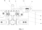
- 10 Flexible screen; 20: First housing; 30: Second housing; 40: Stylus; 50: Transmission structure; 60: Hinge component; 70: Support; 80: Mounting base; 21: Rotation shaft; 51: Transmission rod; 52: Transmission gear assembly; 61: Sliding block; 71: Fixing block; 72: Fixing plate; 81: Mounting groove; 511: First transmission insection; 521: Driving gear; 522: Driven gear; 611: Second transmission insection; and 701: Rotation groove.
- connection may be a fixed connection, a detachable connection, or an integral connection; or the connection may be a mechanical connection or an electrical connection; or the connection may be a direct connection, an indirect connection through an intermediary, or internal communication between two components.
- an electronic device includes: a flexible screen 10, a first housing 20, a second housing 30, a stylus 40, and a transmission structure 50.
- the first housing 20 is movably connected to the second housing 30, the flexible screen 10 is connected to the first housing 20 and the second housing 30, the transmission structure 50 is arranged on the first housing 20, and the stylus 40 is connected to the transmission structure 50.
- the transmission structure 50 drives the stylus 40 to approach the flexible screen 10, to accommodate the stylus 40 in a gap formed after the flexible screen 10 is folded; and in a case that the flexible screen 10 is driven to unfold by the first housing 20 and the second housing 30, the transmission structure 50 drives the stylus 40 to move away from the flexible screen 10, to cause the stylus 40 and the flexible screen 10 to form a preset included angle.
- the first housing 20 is movably connected to the second housing 30, and the flexible screen 10 is connected to the first housing 20 and the second housing 30, so that when the first housing 20 and the second housing 30 move relative to each other, the flexible screen 10 may be driven to fold or unfold by the first housing 20 and the second housing 30.
- the transmission structure 50 is arranged on the first housing 20, and the stylus 40 is connected to the transmission structure 50, so that the transmission structure 50 may transmit power to the stylus 40, to cause the stylus 40 to move.
- the transmission structure 50 drives the stylus 40 to approach the flexible screen 10, to accommodate the stylus 40 in the gap formed after the flexible screen 10 is folded; and when the flexible screen 10 is driven to unfold by the first housing 20 and the second housing 30, the transmission structure 50 drives the stylus 40 to move away from the flexible screen 10, to cause the stylus 40 and the flexible screen 10 to form the preset included angle. That is, by arranging the transmission structure 50 and connecting the stylus 40 to the transmission structure 50, when the flexible screen 10 is folded, the stylus 40 may be accommodated in the gap formed after the flexible screen 10 is folded, and when the flexible screen 10 is unfolded, the stylus 40 and the flexible screen 10 form the preset included angle. This helps arrangement of the stylus 40 on the electronic device, also helps accommodation of the stylus 40, and helps use of the stylus 40 by a user to operate the electronic device when the flexible screen 10 is unfolded.
- the flexible screen 10 is bonded to the first housing 20 and the second housing 30 in a bonding manner, so that the flexible screen 10 is connected to the first housing 20 and the second housing 30.
- a mounting sinking platform may be arranged on both the first housing 20 and the second housing 30, and the flexible screen 10 is bonded to the mounting sinking platform of the first housing 20 and the mounting sinking platform of the second housing 30, so that the flexible screen 10 is flush with a surface of the first housing 20 and a surface of the second housing 30.
- first housing 20 may include a first middle frame and a first rear cover, where the first rear cover is connected to a first side of the first middle frame, the flexible screen 10 is connected to a second side of the first middle frame, and the first side is opposite to the second side.
- second housing 30 may also include a second middle frame and a second rear cover, where the second rear cover is connected to a side of the second middle frame, and the flexible screen 10 is connected to another side of the second middle frame.
- first housing 20 and the second housing 30 may both be an integrally formed housing. Therefore, this is not limited in the embodiments of this application.
- the preset included angle may be set according to an actual requirement.
- the preset included angle is 90 degrees, that is, after the flexible screen 10 is unfolded, the stylus 40 is perpendicular to the flexible screen 10.
- the preset included angle may be 60 degrees, 120 degrees, or 180 degrees, and a specific value of the preset angle is not limited in the embodiments of this application.
- the transmission structure 50 may include a transmission rod 51 and a transmission gear assembly 52.
- the transmission gear assembly 52 is rotatably connected to the first housing 20, a first transmission insection 511 is provided on the transmission rod 51, the transmission gear assembly 52 is engaged with the first transmission insection 511, and the transmission rod 51 is connected to the stylus 40.
- the transmission gear assembly 52 rotates along a first direction to cause the transmission rod 51 to rotate along a first rotation direction, and the transmission rod 51 drives the stylus 40 to approach the flexible screen 10; and in a case that the flexible screen 10 is driven to unfold by the first housing 20 and the second housing 30, the transmission gear assembly 52 rotates along a second direction to cause the transmission rod 51 to rotate along a second rotation direction, and the transmission rod 51 drives the stylus 40 to move away from the flexible screen 10.
- the first direction and the second direction are reverse, and the first rotation direction and the second rotation direction are reverse.
- the transmission gear assembly 52 is rotatably connected to the first housing 20, so that the transmission gear assembly 52 may rotate relative to the first housing 20.
- the first transmission insection 511 is provided on the transmission rod 51, and the transmission gear assembly 52 is engaged with the first transmission insection 511, so that when the transmission gear assembly 52 rotates, the transmission gear assembly 52 drives the transmission rod 51 to rotate.
- the transmission rod 51 is connected to the stylus 40, so that when the transmission rod 51 rotates, the transmission rod 51 may drive the stylus 40 to move, so that the stylus 40 approaches or moves away from the flexible screen 10.
- the transmission gear assembly 52 rotates along the first direction
- the transmission rod 51 is caused to rotate along the first rotation direction
- the transmission rod 51 then drives the stylus 40 to approach the flexible screen 10, so that the stylus 40 may be accommodated in the gap formed after the flexible screen 10 is folded
- the transmission gear assembly 52 rotates along the second direction
- the transmission rod 51 is caused to rotate along the second rotation direction
- the transmission rod 51 then drives the stylus 40 to move away from the flexible screen 10, so that the stylus 40 and the flexible screen 10 form the preset included angle.
- the transmission gear assembly 52 may include a driving gear 521 and a driven gear 522.
- a rotation shaft 21 is arranged on the first housing 20, the driving gear 521 and the driven gear 522 are both sleeved on the rotation shaft 21, the driving gear 521 is connected to the driven gear 522, and the driven gear 522 is engaged with the first transmission insection 511.
- the rotation shaft is arranged on the first housing 20, and the driving gear 521 and the driven gear 522 are both sleeved on the rotation shaft 21, so that the driving gear 521 and the driven gear 522 may both rotate around the rotation shaft 21, that is, the driving gear 521 and the driven gear 522 may rotate coaxially.
- the driving gear 521 is connected to the driven gear 522, and the driven gear 522 is engaged with the first transmission insection 511, so that after the driving gear 521 rotates, the driving gear 521 may drive the driven gear 522 to rotate, and the driven gear 522 is caused to drive the transmission rod 51 to rotate.
- using the driven gear 522 to drive the transmission rod 51 to rotate is equivalent to using the principle of a worm wheel and a worm, where the driven gear 522 is equivalent to a worm wheel, and the transmission rod 51 is equivalent to a worm, and using the driven gear 522 to drive the transmission rod 51 to rotate is equivalent to using the worm wheel to drive the worm to rotate, so that power is transmitted to the stylus 40, and the stylus 40 may rotate as the transmission rod 51 rotates.
- the transmission gear assembly 52 may be driven in different manners to cause the transmission gear assembly 52 to rotate, and details are described by using the following manners as examples:
- the first housing 20 is connected to the second housing 30 through the hinge component 60, so that the first housing 20 and the second housing 30 may move relative to each other. That is, the first housing 20 and the second housing 30 may approach or move away from each other, so that the flexible screen 10 is driven to fold or unfold by the first housing 20 and the second housing 30.
- the hinge component 60 is connected to the transmission gear assembly 52, so that when the flexible screen 10 is driven to fold by the first housing 20 and the second housing 30, the hinge component 60 may drive the transmission gear assembly 52 to rotate along the first direction, the transmission gear assembly 52 may be caused to drive the transmission rod 51 to rotate along the first rotation direction, and the transmission rod 51 then drives the stylus 40 to approach the flexible screen 10, so that the stylus 40 may be accommodated in the gap formed after the flexible screen 10 is folded; and when the flexible screen 10 is driven to unfold by the first housing 20 and the second housing 30, the hinge component 60 may drive the transmission gear assembly 52 to rotate along the second direction, the transmission gear assembly 52 may be caused to drive the transmission rod 51 to rotate along the second rotation direction, and the transmission rod 51 then drives the stylus 40 to move away from the flexible screen 10, so that the stylus 40 and the flexible screen 10 form the preset included angle.
- the hinge component 60 may drive the driving gear 521 to rotate, and the driving gear 521 is caused to drive the driven gear 522 to rotate, so that the driven gear 522 drives the transmission rod 51 to rotate to drive the stylus 40 to move.
- a connection manner of the hinge component 60 and the transmission gear assembly 52 may be that: the hinge component 60 is connected to a sliding block 61, a second transmission insection 611 is provided on the sliding block 61, and the second transmission insection 611 is engaged with the transmission gear assembly 52.
- the hinge component 60 drives the sliding block 61 to slide along a first sliding direction, to cause the sliding block 61 to drive the transmission gear assembly 52 to rotate along the first direction; and in a case that the flexible screen 10 is driven to unfold by the first housing 20 and the second housing 30, the hinge component 60 drives the sliding block 61 to slide along a second sliding direction, to cause the sliding block 61 to drive the transmission gear assembly 52 to rotate along the second direction.
- the first sliding direction and the second sliding direction are reverse.
- the hinge component 60 is connected to the sliding block 61, the second transmission insection 611 is provided on the sliding block 61, and the second transmission insection 611 is engaged with the transmission gear assembly 52. Therefore, when the flexible screen 10 is driven to fold or unfold by the first housing 20 and the second housing 30, the hinge component 60 may drive the sliding block 61 to move, and in a moving process of the sliding block 61, the sliding block 61 drives the transmission gear assembly 52 to rotate, so that the transmission gear assembly 52 drives the transmission rod 51 to rotate. Specifically, when the flexible screen 10 is driven to fold by the first housing 20 and the second housing 30, the hinge component 60 may drive the sliding block 61 to slide along the first sliding direction.
- the sliding block 61 drives the transmission gear assembly 52 to rotate along the first direction
- the transmission gear assembly 52 drives the transmission rod 51 to rotate along the first rotation direction
- the stylus 40 is caused to approach the flexible screen 10, so that the stylus 40 may be finally accommodated in the gap formed after the flexible screen 10 is folded.
- the hinge component 60 may drive the sliding block 61 to slide along the second sliding direction.
- the sliding block 61 drives the transmission gear assembly 52 to rotate along the second direction
- the transmission gear assembly 52 drives the transmission rod 51 to rotate along the second rotation direction
- the stylus 40 is caused to move away from the flexible screen 10, so that the stylus 40 and the flexible screen 10 finally form the preset included angle.
- the second transmission insection 611 on the sliding block 61 may be engaged with the driving gear 521, so that when the hinge component 60 drives the sliding block 61 to move, the sliding block 61 may drive the driving gear 521 to rotate, the driving gear 521 further drives the driven gear 522 to rotate, and the driven gear 522 drives the transmission rod 51 to rotate to drive the stylus 40 to move.
- a driving assembly (not shown in the figure) is arranged in the first housing 20.
- the driving assembly is connected to the transmission gear assembly 52.
- the driving assembly drives the transmission gear assembly 52 to rotate along the first direction; and in a case that the flexible screen 10 is driven to unfold by the first housing 20 and the second housing 30, the driving assembly drives the transmission gear assembly 52 to rotate along the second direction.
- the driving assembly is connected to the transmission gear assembly 52, so that the driving assembly may drive the transmission gear assembly 52 to rotate, the transmission gear assembly 52 may be caused to drive the transmission rod 51 to rotate, and the transmission rod 51 further drives the stylus 40 to move.
- the driving assembly may drive the transmission gear assembly 52 to rotate along the first direction
- the transmission gear assembly 52 drives the transmission rod 51 to rotate along the first rotation direction
- the transmission rod 51 drives the stylus 40 to approach the flexible screen 10.
- the driving assembly may drive the transmission gear assembly 52 to rotate along the second direction
- the transmission gear assembly 52 drives the transmission rod 51 to rotate along the second rotation direction
- the transmission rod 51 drives the stylus 40 to move away from the flexible screen 10.
- a control circuit and a sensor may be arranged in the electronic device, where the sensor is electrically connected to the control circuit, and the control circuit is electrically connected to the driving assembly.
- the sensor may detect that the flexible screen 10 is driven to fold or unfold by the first housing 20 and the second housing 30, and send detected information to the control circuit, and the control circuit controls the driving assembly to drive the transmission gear assembly 52 to rotate.
- the control circuit may be integrated on a circuit board, the circuit board may be a printed circuit board (Printed Circuit Board, PCB), and the control circuit may alternatively be integrated on a flexible printed circuit (Flexible Printed Circuit, FPC).
- the driving assembly may include a driving member and a driving rod.
- the driving member is connected to the driving rod, a driving insection is provided on the driving rod, and the driving insection is engaged with the transmission gear assembly 52.
- the driving member drives the driving rod to rotate along a first driving direction, to cause the driving rod to drive the transmission gear assembly 52 to rotate along the first direction; and in a case that the flexible screen 10 is driven to unfold by the first housing 20 and the second housing 30, the driving member drives the driving rod to rotate along a second driving direction, to cause the driving rod to drive the transmission gear assembly 52 to rotate along the second direction.
- the first driving direction and the second driving direction are reverse.
- the driving member is connected to the driving rod, so that the driving member may drive the driving rod to rotate.
- the driving insection is provided on the driving rod, and the driving insection is engaged with the transmission gear assembly 52, so that when the driving rod rotates, the driving rod may drive the transmission gear assembly 52 to engage, so that the transmission gear assembly 52 drives the transmission rod 51 to rotate, and the transmission rod 51 further drives the stylus 40 to approach or move away from the flexible screen 10.
- the driving member may drive the driving rod to rotate along the first driving direction
- the driving rod drives the transmission gear assembly 52 to rotate along the first direction
- the transmission gear assembly 52 drives the transmission rod 51 to rotate along the first rotation direction, so that the stylus 40 approaches the flexible screen 10.
- the driving member may drive the driving rod to rotate along the second driving direction
- the driving rod drives the transmission gear assembly 52 to rotate along the second direction
- the transmission gear assembly 52 drives the transmission rod 51 to rotate along the second rotation direction, so that the stylus 40 moves away from the flexible screen 10.
- the driving member may be a motor.
- the driving insection on the driving rod may be engaged with the driving gear 521.
- the driving member drives the driving rod to rotate
- the driving rod drives the driving gear 521 to rotate
- the driving gear 521 drives the driven gear 522 to rotate
- the driven gear 522 drives the transmission rod 51 to rotate
- the transmission rod 51 further drives the stylus 40 to move.
- the driving rod drives the driving gear 521 to rotate, and this is equivalent to using the principle of a worm wheel and a worm.
- the driving rod is equivalent to a worm
- the transmission gear assembly 52 is equivalent to a worm wheel.
- the driven gear 522 drives the transmission rod 51 to rotate, and this is also equivalent to using the principle of a worm wheel and a worm.
- the driven gear 522 is equivalent to a worm wheel
- the transmission rod 51 is equivalent to a worm.
- the driving assembly may include a driving member and a rack.
- the driving member is connected to the rack.
- An output shaft of the driving member may be connected to a lead screw nut structure, where the output shaft is connected to a lead screw, a nut is nested on the lead screw, and the nut is connected to the rack, so that the driving member is connected to the rack.
- the rack may be engaged with the driving gear 521.
- the driving member drives, through the lead screw nut structure, the rack to move along a first moving direction, the rack drives the driving gear 521 to rotate along the first direction, the driving gear 521 drives the driven gear 522 to rotate, the driven gear 522 drives the transmission rod 51 to rotate along the first rotation direction, and the transmission rod 51 drives the stylus 40 to approach the flexible screen 10.
- the driving member drives, through the lead screw nut structure, the rack to move along a second moving direction
- the rack drives the driving gear 521 to rotate along the second direction
- the driving gear 521 drives the driven gear 522 to rotate
- the driven gear 522 drives the transmission rod 51 to rotate along the second rotation direction
- the transmission rod 51 drives the stylus 40 to move away from the flexible screen 10.
- the first moving direction and the second moving direction are reverse.
- a manner in which the transmission rod 51 is rotatably connected to the first housing 20 may be that: as shown in FIG. 4 , a support 70 is arranged on the first housing 20, and the transmission rod 51 is rotatably connected to the support 70. That is, by arranging the support 70 on the first housing 20, the transmission rod 51 is rotatably connected to the support 70, so that the transmission rod 51 is rotatably connected to the first housing 20. In addition, by arranging the support 70, rotatable connection between the transmission rod 51 and the first housing 20 may be facilitated.
- a manner in which the transmission rod 51 is rotatably connected to the support 70 may be that: as shown in FIG. 4 and FIG. 6 , a rotation groove 701 is provided on the support 70. At least a portion of the transmission rod 51 is located in the rotation groove 701, and the first transmission insection 511 is located in external space of the rotation groove 701.
- the rotation groove 701 is provided on the support 70, and at least a portion of the transmission rod 51 is located in the rotation groove 701, so that the rotation groove 701 may perform a certain limiting function on the transmission rod 51, thereby preventing a problem that a position of the transmission rod 51 offsets in a rotation process.
- the transmission rod 51 may rotate in the rotation groove 701, so that the transmission rod 51 is rotatably connected to the support 70. That is, by providing the rotation groove 701 on the support 70, rotatable connection between the transmission rod 51 and the support 70 may be facilitated.
- a quantity of the rotation grooves 701 may be set according to an actual requirement.
- the quantity of the rotation grooves 701 may be two or may be one, and the quantity of the rotation grooves 701 is not limited in the embodiments of this application.
- the support 70 may include a fixing block 71 and a fixing plate 72, and the fixing plate 72 is detachably connected to the fixing block 71.
- the fixing block 71 is arranged on the first housing 20, the rotation groove 701 is provided on the fixing block 71, and the transmission rod 51 is located between the fixing block 71 and the fixing plate 72.
- the support 70 includes the fixing block 71 and the fixing plate 72, the fixing block 71 is arranged on the first housing 20, and the rotation groove 701 is provided on the fixing block 71, so that at least a portion of the transmission rod 51 may be located in the rotation groove 701.
- the fixing plate 72 is detachably connected to the fixing block 71, so that after the fixing plate 72 is mounted on the fixing block 71, the transmission rod 51 may be located between the fixing plate 72 and the fixing block 71. Therefore, the fixing plate 72 and the rotation groove 701 perform a limiting function on the transmission rod 51 simultaneously, thereby preventing occurrence of a problem that the transmission rod 51 separates from the rotation groove 701 in a rotation process.
- the rotation groove 701 on the fixing block 71 may be provided according to an actual requirement.
- the quantity of the rotation grooves 701 may be two.
- the first transmission insection 511 on the transmission rod 51 may be located between the two rotation grooves 701.
- the quantity of the rotation grooves 701 may alternatively be one, and the quantity is not limited in the embodiments of this application.
- the fixing plate 72 may be connected to the fixing block 71 through bolts, so that the fixing plate 72 is detachably connected to the fixing block 71.
- the fixing plate 72 may alternatively be detachably connected to the fixing block 71 in a clamping manner, where a fastener may be arranged on the fixing plate 72, and a clamping groove may be provided on the fixing block 71.
- a manner in which the fixing plate 72 is detachably connected to the fixing block 71 is not limited in the embodiments of this application.
- a manner in which the stylus 40 is connected to the transmission rod 51 may be that: as shown in FIG. 4 , the electronic device may further include a mounting base 80.
- the mounting base 80 is connected to the transmission rod 51, and the stylus 40 is detachably connected to the mounting base 80.
- the mounting base 80 may be mounted on the transmission rod 51, to detachably connect the stylus 40 to the mounting base 80, so that the stylus 40 is connected to the transmission rod 51. That is, by arranging the mounting base 80, connection between the stylus 40 and the transmission rod 51 may be facilitated.
- the manner in which the stylus 40 is connected to the transmission rod 51 may alternatively be that: the stylus 40 is directly connected to the transmission rod 51.
- the stylus 40 may be connected to the transmission rod 51 in a clamping manner, that is, a clamping groove may be provided on the transmission rod 51, and a fastener may be arranged on the stylus, so that the stylus 40 is clamped to the transmission rod 51 through the fastener and the clamping groove.
- a manner in which the stylus 40 is detachably connected to the mounting base 80 may be that: a mounting groove 81 is provided on the mounting base 80, a first magnetic member is arranged in the mounting groove 81, a second magnetic member is arranged on a mounting end of the stylus 40, the mounting end of the stylus 40 is located in the mounting groove 81, and magnetism of the first magnetic member and magnetism of the second magnetic member are opposite.
- the second magnetic member may be arranged on the mounting end of the stylus 40.
- the first magnetic member may be attracted to the second magnetic member, thereby preventing the stylus 40 from falling from the mounting groove 81.
- the user may take the stylus 40 out of the mounting groove 81.
- the stylus 40 may alternatively be detachably connected to the mounting base 80 in another manner.
- a clamping groove is provided on the mounting base 80
- a fastener is arranged on the stylus 40, and the fastener matches the clamping groove, so that the stylus 40 is detachably connected to the mounting base 80.
- the manner in which the stylus 40 is detachably connected to the mounting base 80 is not limited in the embodiments of this application.
- the electronic device includes but not limited to a mobile phone, a tablet computer, a notebook computer, a palmtop computer, an on-board terminal, a wearable device, and a pedometer.
- the first housing 20 is movably connected to the second housing 30, and the flexible screen 10 is connected to the first housing 20 and the second housing 30, so that when the first housing 20 and the second housing 30 move relative to each other, the flexible screen 10 may be driven to fold or unfold by the first housing 20 and the second housing 30.
- the transmission structure 50 is arranged on the first housing 20, and the stylus 40 is connected to the transmission structure 50, so that the transmission structure 50 may transmit power to the stylus 40, to cause the stylus 40 to move.
- the transmission structure 50 drives the stylus 40 to approach the flexible screen 10, to accommodate the stylus 40 in the gap formed after the flexible screen 10 is folded; and when the flexible screen 10 is driven to unfold by the first housing 20 and the second housing 30, the transmission structure 50 drives the stylus 40 to move away from the flexible screen 10, to cause the stylus 40 and the flexible screen 10 to form the preset included angle. That is, by arranging the transmission structure 50 and connecting the stylus 40 to the transmission structure 50, when the flexible screen 10 is folded, the stylus 40 may be accommodated in the gap formed after the flexible screen 10 is folded, and when the flexible screen 10 is unfolded, the stylus 40 and the flexible screen 10 form the preset included angle. This helps arrangement of the stylus 40 on the electronic device, also helps accommodation of the stylus 40, and helps use of the stylus 40 by a user to operate the electronic device when the flexible screen 10 is unfolded.
Landscapes
- Engineering & Computer Science (AREA)
- Theoretical Computer Science (AREA)
- General Engineering & Computer Science (AREA)
- Computer Hardware Design (AREA)
- Physics & Mathematics (AREA)
- General Physics & Mathematics (AREA)
- Human Computer Interaction (AREA)
- Microelectronics & Electronic Packaging (AREA)
- Mathematical Physics (AREA)
- Casings For Electric Apparatus (AREA)
- Catching Or Destruction (AREA)
- Devices For Indicating Variable Information By Combining Individual Elements (AREA)
- Telephone Set Structure (AREA)
Abstract
Description
- This application claims priority to
Chinese Patent Application No. 202110755128.9, entitled "ELECTRONIC DEVICE" filed with the China National Intellectual Property Administration on July 2, 2021 - This application relates to the technical field of electronic devices, and specifically, to an electronic device.
- With the advancement of science and technology, an electronic device has increasingly full functions. Generally, the electronic device includes a flexible screen and a housing, where the flexible screen is arranged on the housing, and the flexible screen may be driven to fold or unfold by the housing. However, a user can hardly arrange a stylus on the electronic device, and consequently, it is inconvenient for the user to operate the electronic device.
- Embodiments of this application provide an electronic device, to resolve the inconvenience of a user in operating an electronic device since the user can hardly arrange a stylus on the electronic device in the related art.
- In order to resolve the foregoing technical problem, this application is implemented as follows:
- An embodiment of this application provides an electronic device, including: a flexible screen, a first housing, a second housing, a stylus, and a transmission structure, where
- the first housing is movably connected to the second housing, the flexible screen is connected to the first housing and the second housing, the transmission structure is arranged on the first housing, and the stylus is connected to the transmission structure;
- in a case that the flexible screen is driven to fold by the first housing and the second housing, the transmission structure drives the stylus to approach the flexible screen, to accommodate the stylus in a gap formed after the flexible screen is folded; and
- in a case that the flexible screen is driven to unfold by the first housing and the second housing, the transmission structure drives the stylus to move away from the flexible screen, to cause the stylus and the flexible screen to form a preset included angle.
- In the embodiments of this application, the first housing is movably connected to the second housing, and the flexible screen is connected to the first housing and the second housing, so that when the first housing and the second housing move relative to each other, the flexible screen may be driven to fold or unfold by the first housing and the second housing. The transmission structure is arranged on the first housing, and the stylus is connected to the transmission structure, so that the transmission structure may transmit power to the stylus, to cause the stylus to move. Specifically, when the flexible screen is driven to fold by the first housing and the second housing, the transmission structure drives the stylus to approach the flexible screen, to accommodate the stylus in the gap formed after the flexible screen is folded; and when the flexible screen is driven to unfold by the first housing and the second housing, the transmission structure drives the stylus to move away from the flexible screen, to cause the stylus and the flexible screen to form the preset included angle. That is, by arranging the transmission structure and connecting the stylus to the transmission structure, when the flexible screen is folded, the stylus may be accommodated in the gap formed after the flexible screen is folded, and when the flexible screen is unfolded, the stylus and the flexible screen form the preset included angle. This helps arrangement of the stylus on the electronic device, also helps accommodation of the stylus, and helps use of the stylus by the user to operate the electronic device when the flexible screen is unfolded.
-
-
FIG. 1 is a first schematic diagram of an electronic device in an unfolded state according to an embodiment of this application; -
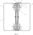
FIG. 2 is a second schematic diagram of an electronic device in an unfolded state according to an embodiment of this application; -
FIG. 3 is a third schematic diagram of an electronic device in an unfolded state according to an embodiment of this application; -
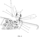
FIG. 4 is a first partial exploded view of an electronic device according to an embodiment of this application; -
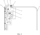
FIG. 5 is a schematic diagram of an electronic device in a folded state according to an embodiment of this application; -
FIG. 6 is a second partial exploded view of an electronic device according to an embodiment of this application; and -
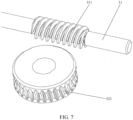
FIG. 7 is an exploded view of a transmission rod and a driven gear according to an embodiment of this application. - 10: Flexible screen; 20: First housing; 30: Second housing; 40: Stylus; 50: Transmission structure; 60: Hinge component; 70: Support; 80: Mounting base; 21: Rotation shaft; 51: Transmission rod; 52: Transmission gear assembly; 61: Sliding block; 71: Fixing block; 72: Fixing plate; 81: Mounting groove; 511: First transmission insection; 521: Driving gear; 522: Driven gear; 611: Second transmission insection; and 701: Rotation groove.
- The following clearly and completely describes the technical solutions in the embodiments of this application with reference to the accompanying drawings in the embodiments of this application. Apparently, the described embodiments are some embodiments of this application rather than all of the embodiments. All other embodiments obtained by a person of ordinary skill in the art based on the embodiments of this application without creative efforts shall fall within the protection scope of this application.
- Therefore, a feature limited by the term "first" or "second" in the specification and claims of this application may explicitly or implicitly include one or more of the features. In descriptions of the present invention, unless otherwise stated, "a plurality of" means two or more. In addition, in the specification and claims, "and/or" indicates at least one of associated objects, and the character "/" generally indicates an "or" relationship between the associated obj ects.
- In the description of the present invention, it should be noted that, unless otherwise explicitly specified and defined, the terms such as "mount", "connect", and "connection" should be understood in a broad sense. For example, the connection may be a fixed connection, a detachable connection, or an integral connection; or the connection may be a mechanical connection or an electrical connection; or the connection may be a direct connection, an indirect connection through an intermediary, or internal communication between two components. A person of ordinary skill in the art may understand specific meanings of the foregoing terms in the present invention according to a specific situation.
- It should be understood that, "one embodiment" or "an embodiment" mentioned throughout the specification indicates that a particular feature, structure, or characteristic that is related to the embodiment is included in at least one embodiment of this application. Therefore, "in one embodiment" or "in an embodiment" that appears throughout the entire specification does not necessarily mean a same embodiment. In addition, the particular feature, structure, or characteristic may be combined in one or more embodiments in any proper manner.
- As shown in
FIG. 1 to FIG. 7 , an electronic device includes: aflexible screen 10, afirst housing 20, asecond housing 30, astylus 40, and atransmission structure 50. - The
first housing 20 is movably connected to thesecond housing 30, theflexible screen 10 is connected to thefirst housing 20 and thesecond housing 30, thetransmission structure 50 is arranged on thefirst housing 20, and thestylus 40 is connected to thetransmission structure 50. In a case that theflexible screen 10 is driven to fold by thefirst housing 20 and thesecond housing 30, thetransmission structure 50 drives thestylus 40 to approach theflexible screen 10, to accommodate thestylus 40 in a gap formed after theflexible screen 10 is folded; and in a case that theflexible screen 10 is driven to unfold by thefirst housing 20 and thesecond housing 30, thetransmission structure 50 drives thestylus 40 to move away from theflexible screen 10, to cause thestylus 40 and theflexible screen 10 to form a preset included angle. - In the embodiments of this application, the
first housing 20 is movably connected to thesecond housing 30, and theflexible screen 10 is connected to thefirst housing 20 and thesecond housing 30, so that when thefirst housing 20 and thesecond housing 30 move relative to each other, theflexible screen 10 may be driven to fold or unfold by thefirst housing 20 and thesecond housing 30. Thetransmission structure 50 is arranged on thefirst housing 20, and thestylus 40 is connected to thetransmission structure 50, so that thetransmission structure 50 may transmit power to thestylus 40, to cause thestylus 40 to move. Specifically, when theflexible screen 10 is driven to fold by thefirst housing 20 and thesecond housing 30, thetransmission structure 50 drives thestylus 40 to approach theflexible screen 10, to accommodate thestylus 40 in the gap formed after theflexible screen 10 is folded; and when theflexible screen 10 is driven to unfold by thefirst housing 20 and thesecond housing 30, thetransmission structure 50 drives thestylus 40 to move away from theflexible screen 10, to cause thestylus 40 and theflexible screen 10 to form the preset included angle. That is, by arranging thetransmission structure 50 and connecting thestylus 40 to thetransmission structure 50, when theflexible screen 10 is folded, thestylus 40 may be accommodated in the gap formed after theflexible screen 10 is folded, and when theflexible screen 10 is unfolded, thestylus 40 and theflexible screen 10 form the preset included angle. This helps arrangement of thestylus 40 on the electronic device, also helps accommodation of thestylus 40, and helps use of thestylus 40 by a user to operate the electronic device when theflexible screen 10 is unfolded. - It should be noted that, in the embodiments of this application, the
flexible screen 10 is bonded to thefirst housing 20 and thesecond housing 30 in a bonding manner, so that theflexible screen 10 is connected to thefirst housing 20 and thesecond housing 30. A mounting sinking platform may be arranged on both thefirst housing 20 and thesecond housing 30, and theflexible screen 10 is bonded to the mounting sinking platform of thefirst housing 20 and the mounting sinking platform of thesecond housing 30, so that theflexible screen 10 is flush with a surface of thefirst housing 20 and a surface of thesecond housing 30. In addition, thefirst housing 20 may include a first middle frame and a first rear cover, where the first rear cover is connected to a first side of the first middle frame, theflexible screen 10 is connected to a second side of the first middle frame, and the first side is opposite to the second side. Similarly, thesecond housing 30 may also include a second middle frame and a second rear cover, where the second rear cover is connected to a side of the second middle frame, and theflexible screen 10 is connected to another side of the second middle frame. Certainly, thefirst housing 20 and thesecond housing 30 may both be an integrally formed housing. Therefore, this is not limited in the embodiments of this application. - In addition, in the embodiments of this application, the preset included angle may be set according to an actual requirement. For example, the preset included angle is 90 degrees, that is, after the
flexible screen 10 is unfolded, thestylus 40 is perpendicular to theflexible screen 10. In another example, the preset included angle may be 60 degrees, 120 degrees, or 180 degrees, and a specific value of the preset angle is not limited in the embodiments of this application. - In addition, in some embodiments, as shown in
FIG. 4 , thetransmission structure 50 may include atransmission rod 51 and atransmission gear assembly 52. Thetransmission gear assembly 52 is rotatably connected to thefirst housing 20, afirst transmission insection 511 is provided on thetransmission rod 51, thetransmission gear assembly 52 is engaged with thefirst transmission insection 511, and thetransmission rod 51 is connected to thestylus 40. In a case that theflexible screen 10 is driven to fold by thefirst housing 20 and thesecond housing 30, thetransmission gear assembly 52 rotates along a first direction to cause thetransmission rod 51 to rotate along a first rotation direction, and thetransmission rod 51 drives thestylus 40 to approach theflexible screen 10; and in a case that theflexible screen 10 is driven to unfold by thefirst housing 20 and thesecond housing 30, thetransmission gear assembly 52 rotates along a second direction to cause thetransmission rod 51 to rotate along a second rotation direction, and thetransmission rod 51 drives thestylus 40 to move away from theflexible screen 10. The first direction and the second direction are reverse, and the first rotation direction and the second rotation direction are reverse. - The
transmission gear assembly 52 is rotatably connected to thefirst housing 20, so that thetransmission gear assembly 52 may rotate relative to thefirst housing 20. Thefirst transmission insection 511 is provided on thetransmission rod 51, and thetransmission gear assembly 52 is engaged with thefirst transmission insection 511, so that when thetransmission gear assembly 52 rotates, thetransmission gear assembly 52 drives thetransmission rod 51 to rotate. Thetransmission rod 51 is connected to thestylus 40, so that when thetransmission rod 51 rotates, thetransmission rod 51 may drive thestylus 40 to move, so that thestylus 40 approaches or moves away from theflexible screen 10. Specifically, when theflexible screen 10 is driven to fold by thefirst housing 20 and thesecond housing 30, thetransmission gear assembly 52 rotates along the first direction, thetransmission rod 51 is caused to rotate along the first rotation direction, and thetransmission rod 51 then drives thestylus 40 to approach theflexible screen 10, so that thestylus 40 may be accommodated in the gap formed after theflexible screen 10 is folded; and when theflexible screen 10 is driven to unfold by thefirst housing 20 and thesecond housing 30, thetransmission gear assembly 52 rotates along the second direction, thetransmission rod 51 is caused to rotate along the second rotation direction, and thetransmission rod 51 then drives thestylus 40 to move away from theflexible screen 10, so that thestylus 40 and theflexible screen 10 form the preset included angle. - In addition, in the embodiments of this application, as shown in
FIG. 4 , thetransmission gear assembly 52 may include adriving gear 521 and a drivengear 522. Arotation shaft 21 is arranged on thefirst housing 20, thedriving gear 521 and the drivengear 522 are both sleeved on therotation shaft 21, thedriving gear 521 is connected to the drivengear 522, and the drivengear 522 is engaged with thefirst transmission insection 511. - The rotation shaft is arranged on the
first housing 20, and thedriving gear 521 and the drivengear 522 are both sleeved on therotation shaft 21, so that thedriving gear 521 and the drivengear 522 may both rotate around therotation shaft 21, that is, thedriving gear 521 and the drivengear 522 may rotate coaxially. Thedriving gear 521 is connected to the drivengear 522, and the drivengear 522 is engaged with thefirst transmission insection 511, so that after thedriving gear 521 rotates, thedriving gear 521 may drive the drivengear 522 to rotate, and the drivengear 522 is caused to drive thetransmission rod 51 to rotate. In the embodiments of this application, using the drivengear 522 to drive thetransmission rod 51 to rotate is equivalent to using the principle of a worm wheel and a worm, where the drivengear 522 is equivalent to a worm wheel, and thetransmission rod 51 is equivalent to a worm, and using the drivengear 522 to drive thetransmission rod 51 to rotate is equivalent to using the worm wheel to drive the worm to rotate, so that power is transmitted to thestylus 40, and thestylus 40 may rotate as thetransmission rod 51 rotates. - In addition, in the embodiments of this application, the
transmission gear assembly 52 may be driven in different manners to cause thetransmission gear assembly 52 to rotate, and details are described by using the following manners as examples: - (1) As shown in
FIG. 2 , thefirst housing 20 is connected to thesecond housing 30 through ahinge component 60. Thehinge component 60 is connected to thetransmission gear assembly 52. In a case that theflexible screen 10 is driven to fold by thefirst housing 20 and thesecond housing 30, thehinge component 60 drives thetransmission gear assembly 52 to rotate along the first direction; and in a case that theflexible screen 10 is driven to unfold by thefirst housing 20 and thesecond housing 30, thehinge component 60 drives thetransmission gear assembly 52 to rotate along the second direction. - The
first housing 20 is connected to thesecond housing 30 through thehinge component 60, so that thefirst housing 20 and thesecond housing 30 may move relative to each other. That is, thefirst housing 20 and thesecond housing 30 may approach or move away from each other, so that theflexible screen 10 is driven to fold or unfold by thefirst housing 20 and thesecond housing 30. Thehinge component 60 is connected to thetransmission gear assembly 52, so that when theflexible screen 10 is driven to fold by thefirst housing 20 and thesecond housing 30, thehinge component 60 may drive thetransmission gear assembly 52 to rotate along the first direction, thetransmission gear assembly 52 may be caused to drive thetransmission rod 51 to rotate along the first rotation direction, and thetransmission rod 51 then drives thestylus 40 to approach theflexible screen 10, so that thestylus 40 may be accommodated in the gap formed after theflexible screen 10 is folded; and when theflexible screen 10 is driven to unfold by thefirst housing 20 and thesecond housing 30, thehinge component 60 may drive thetransmission gear assembly 52 to rotate along the second direction, thetransmission gear assembly 52 may be caused to drive thetransmission rod 51 to rotate along the second rotation direction, and thetransmission rod 51 then drives thestylus 40 to move away from theflexible screen 10, so that thestylus 40 and theflexible screen 10 form the preset included angle. - It should be noted that, when the
transmission gear assembly 52 includes thedriving gear 521 and the drivengear 522, thehinge component 60 may drive thedriving gear 521 to rotate, and thedriving gear 521 is caused to drive the drivengear 522 to rotate, so that the drivengear 522 drives thetransmission rod 51 to rotate to drive thestylus 40 to move. - In addition, in the embodiments of this application, a connection manner of the
hinge component 60 and thetransmission gear assembly 52 may be that: thehinge component 60 is connected to a slidingblock 61, asecond transmission insection 611 is provided on the slidingblock 61, and thesecond transmission insection 611 is engaged with thetransmission gear assembly 52. In a case that theflexible screen 10 is driven to fold by thefirst housing 20 and thesecond housing 30, thehinge component 60 drives the slidingblock 61 to slide along a first sliding direction, to cause the slidingblock 61 to drive thetransmission gear assembly 52 to rotate along the first direction; and in a case that theflexible screen 10 is driven to unfold by thefirst housing 20 and thesecond housing 30, thehinge component 60 drives the slidingblock 61 to slide along a second sliding direction, to cause the slidingblock 61 to drive thetransmission gear assembly 52 to rotate along the second direction. The first sliding direction and the second sliding direction are reverse. - The
hinge component 60 is connected to the slidingblock 61, thesecond transmission insection 611 is provided on the slidingblock 61, and thesecond transmission insection 611 is engaged with thetransmission gear assembly 52. Therefore, when theflexible screen 10 is driven to fold or unfold by thefirst housing 20 and thesecond housing 30, thehinge component 60 may drive the slidingblock 61 to move, and in a moving process of the slidingblock 61, the slidingblock 61 drives thetransmission gear assembly 52 to rotate, so that thetransmission gear assembly 52 drives thetransmission rod 51 to rotate. Specifically, when theflexible screen 10 is driven to fold by thefirst housing 20 and thesecond housing 30, thehinge component 60 may drive the slidingblock 61 to slide along the first sliding direction. In this case, the slidingblock 61 drives thetransmission gear assembly 52 to rotate along the first direction, thetransmission gear assembly 52 drives thetransmission rod 51 to rotate along the first rotation direction, and thestylus 40 is caused to approach theflexible screen 10, so that thestylus 40 may be finally accommodated in the gap formed after theflexible screen 10 is folded. When theflexible screen 10 is driven to unfold by thefirst housing 20 and thesecond housing 30, thehinge component 60 may drive the slidingblock 61 to slide along the second sliding direction. In this case, the slidingblock 61 drives thetransmission gear assembly 52 to rotate along the second direction, thetransmission gear assembly 52 drives thetransmission rod 51 to rotate along the second rotation direction, and thestylus 40 is caused to move away from theflexible screen 10, so that thestylus 40 and theflexible screen 10 finally form the preset included angle. - It should be noted that, when the
transmission gear assembly 52 includes thedriving gear 521 and the drivengear 522, thesecond transmission insection 611 on the slidingblock 61 may be engaged with thedriving gear 521, so that when thehinge component 60 drives the slidingblock 61 to move, the slidingblock 61 may drive thedriving gear 521 to rotate, thedriving gear 521 further drives the drivengear 522 to rotate, and the drivengear 522 drives thetransmission rod 51 to rotate to drive thestylus 40 to move. - (2) A driving assembly (not shown in the figure) is arranged in the
first housing 20. The driving assembly is connected to thetransmission gear assembly 52. In a case that theflexible screen 10 is driven to fold by thefirst housing 20 and thesecond housing 30, the driving assembly drives thetransmission gear assembly 52 to rotate along the first direction; and in a case that theflexible screen 10 is driven to unfold by thefirst housing 20 and thesecond housing 30, the driving assembly drives thetransmission gear assembly 52 to rotate along the second direction. - The driving assembly is connected to the
transmission gear assembly 52, so that the driving assembly may drive thetransmission gear assembly 52 to rotate, thetransmission gear assembly 52 may be caused to drive thetransmission rod 51 to rotate, and thetransmission rod 51 further drives thestylus 40 to move. Specifically, when theflexible screen 10 is driven to fold by thefirst housing 20 and thesecond housing 30, the driving assembly may drive thetransmission gear assembly 52 to rotate along the first direction, thetransmission gear assembly 52 drives thetransmission rod 51 to rotate along the first rotation direction, and thetransmission rod 51 drives thestylus 40 to approach theflexible screen 10. When theflexible screen 10 is driven to unfold by thefirst housing 20 and thesecond housing 30, the driving assembly may drive thetransmission gear assembly 52 to rotate along the second direction, thetransmission gear assembly 52 drives thetransmission rod 51 to rotate along the second rotation direction, and thetransmission rod 51 drives thestylus 40 to move away from theflexible screen 10. - It should be noted that, a control circuit and a sensor may be arranged in the electronic device, where the sensor is electrically connected to the control circuit, and the control circuit is electrically connected to the driving assembly. The sensor may detect that the
flexible screen 10 is driven to fold or unfold by thefirst housing 20 and thesecond housing 30, and send detected information to the control circuit, and the control circuit controls the driving assembly to drive thetransmission gear assembly 52 to rotate. The control circuit may be integrated on a circuit board, the circuit board may be a printed circuit board (Printed Circuit Board, PCB), and the control circuit may alternatively be integrated on a flexible printed circuit (Flexible Printed Circuit, FPC). - In addition, in the embodiments of this application, the driving assembly may include a driving member and a driving rod. The driving member is connected to the driving rod, a driving insection is provided on the driving rod, and the driving insection is engaged with the
transmission gear assembly 52. In a case that theflexible screen 10 is driven to fold by thefirst housing 20 and thesecond housing 30, the driving member drives the driving rod to rotate along a first driving direction, to cause the driving rod to drive thetransmission gear assembly 52 to rotate along the first direction; and in a case that theflexible screen 10 is driven to unfold by thefirst housing 20 and thesecond housing 30, the driving member drives the driving rod to rotate along a second driving direction, to cause the driving rod to drive thetransmission gear assembly 52 to rotate along the second direction. The first driving direction and the second driving direction are reverse. - The driving member is connected to the driving rod, so that the driving member may drive the driving rod to rotate. The driving insection is provided on the driving rod, and the driving insection is engaged with the
transmission gear assembly 52, so that when the driving rod rotates, the driving rod may drive thetransmission gear assembly 52 to engage, so that thetransmission gear assembly 52 drives thetransmission rod 51 to rotate, and thetransmission rod 51 further drives thestylus 40 to approach or move away from theflexible screen 10. Specifically, when theflexible screen 10 is driven to fold by thefirst housing 20 and thesecond housing 30, the driving member may drive the driving rod to rotate along the first driving direction, the driving rod drives thetransmission gear assembly 52 to rotate along the first direction, and thetransmission gear assembly 52 drives thetransmission rod 51 to rotate along the first rotation direction, so that thestylus 40 approaches theflexible screen 10. When theflexible screen 10 is driven to unfold by thefirst housing 20 and thesecond housing 30, the driving member may drive the driving rod to rotate along the second driving direction, the driving rod drives thetransmission gear assembly 52 to rotate along the second direction, and thetransmission gear assembly 52 drives thetransmission rod 51 to rotate along the second rotation direction, so that thestylus 40 moves away from theflexible screen 10. - It should be noted that, in the embodiments of this application, the driving member may be a motor.
- In addition, in the embodiments of this application, when the
transmission gear assembly 52 includes thedriving gear 521 and the drivengear 522, the driving insection on the driving rod may be engaged with thedriving gear 521. When the driving member drives the driving rod to rotate, the driving rod drives thedriving gear 521 to rotate, thedriving gear 521 drives the drivengear 522 to rotate, the drivengear 522 drives thetransmission rod 51 to rotate, and thetransmission rod 51 further drives thestylus 40 to move. In the embodiments of this application, after the driving rod rotates, the driving rod drives thedriving gear 521 to rotate, and this is equivalent to using the principle of a worm wheel and a worm. In this case, the driving rod is equivalent to a worm, and thetransmission gear assembly 52 is equivalent to a worm wheel. After the drivengear 522 rotates, the drivengear 522 drives thetransmission rod 51 to rotate, and this is also equivalent to using the principle of a worm wheel and a worm. In this case, the drivengear 522 is equivalent to a worm wheel, and thetransmission rod 51 is equivalent to a worm. - In addition, in the embodiments of this application, the driving assembly may include a driving member and a rack. The driving member is connected to the rack. An output shaft of the driving member may be connected to a lead screw nut structure, where the output shaft is connected to a lead screw, a nut is nested on the lead screw, and the nut is connected to the rack, so that the driving member is connected to the rack. In addition, the rack may be engaged with the
driving gear 521. In a case that theflexible screen 10 is driven to fold by thefirst housing 20 and thesecond housing 30, the driving member drives, through the lead screw nut structure, the rack to move along a first moving direction, the rack drives thedriving gear 521 to rotate along the first direction, thedriving gear 521 drives the drivengear 522 to rotate, the drivengear 522 drives thetransmission rod 51 to rotate along the first rotation direction, and thetransmission rod 51 drives thestylus 40 to approach theflexible screen 10. In a case that theflexible screen 10 is driven to unfold by thefirst housing 20 and thesecond housing 30, the driving member drives, through the lead screw nut structure, the rack to move along a second moving direction, the rack drives thedriving gear 521 to rotate along the second direction, thedriving gear 521 drives the drivengear 522 to rotate, the drivengear 522 drives thetransmission rod 51 to rotate along the second rotation direction, and thetransmission rod 51 drives thestylus 40 to move away from theflexible screen 10. The first moving direction and the second moving direction are reverse. - In addition, in the embodiments of this application, a manner in which the
transmission rod 51 is rotatably connected to thefirst housing 20 may be that: as shown inFIG. 4 , asupport 70 is arranged on thefirst housing 20, and thetransmission rod 51 is rotatably connected to thesupport 70. That is, by arranging thesupport 70 on thefirst housing 20, thetransmission rod 51 is rotatably connected to thesupport 70, so that thetransmission rod 51 is rotatably connected to thefirst housing 20. In addition, by arranging thesupport 70, rotatable connection between thetransmission rod 51 and thefirst housing 20 may be facilitated. - In addition, in some embodiments, a manner in which the
transmission rod 51 is rotatably connected to thesupport 70 may be that: as shown inFIG. 4 andFIG. 6 , arotation groove 701 is provided on thesupport 70. At least a portion of thetransmission rod 51 is located in therotation groove 701, and thefirst transmission insection 511 is located in external space of therotation groove 701. - The
rotation groove 701 is provided on thesupport 70, and at least a portion of thetransmission rod 51 is located in therotation groove 701, so that therotation groove 701 may perform a certain limiting function on thetransmission rod 51, thereby preventing a problem that a position of thetransmission rod 51 offsets in a rotation process. In addition, thetransmission rod 51 may rotate in therotation groove 701, so that thetransmission rod 51 is rotatably connected to thesupport 70. That is, by providing therotation groove 701 on thesupport 70, rotatable connection between thetransmission rod 51 and thesupport 70 may be facilitated. - It should be noted that, a quantity of the
rotation grooves 701 may be set according to an actual requirement. For example, the quantity of therotation grooves 701 may be two or may be one, and the quantity of therotation grooves 701 is not limited in the embodiments of this application. - In addition, in some embodiments, as shown in
FIG. 4 , thesupport 70 may include a fixingblock 71 and a fixingplate 72, and the fixingplate 72 is detachably connected to the fixingblock 71. The fixingblock 71 is arranged on thefirst housing 20, therotation groove 701 is provided on the fixingblock 71, and thetransmission rod 51 is located between the fixingblock 71 and the fixingplate 72. - The
support 70 includes the fixingblock 71 and the fixingplate 72, the fixingblock 71 is arranged on thefirst housing 20, and therotation groove 701 is provided on the fixingblock 71, so that at least a portion of thetransmission rod 51 may be located in therotation groove 701. The fixingplate 72 is detachably connected to the fixingblock 71, so that after the fixingplate 72 is mounted on the fixingblock 71, thetransmission rod 51 may be located between the fixingplate 72 and the fixingblock 71. Therefore, the fixingplate 72 and therotation groove 701 perform a limiting function on thetransmission rod 51 simultaneously, thereby preventing occurrence of a problem that thetransmission rod 51 separates from therotation groove 701 in a rotation process. - It should be noted that, the
rotation groove 701 on the fixingblock 71 may be provided according to an actual requirement. For example, the quantity of therotation grooves 701 may be two. In this case, after thetransmission rod 51 is mounted in therotation groove 701, thefirst transmission insection 511 on thetransmission rod 51 may be located between the tworotation grooves 701. Certainly, the quantity of therotation grooves 701 may alternatively be one, and the quantity is not limited in the embodiments of this application. - In addition, in the embodiments of this application, the fixing
plate 72 may be connected to the fixingblock 71 through bolts, so that the fixingplate 72 is detachably connected to the fixingblock 71. Certainly, the fixingplate 72 may alternatively be detachably connected to the fixingblock 71 in a clamping manner, where a fastener may be arranged on the fixingplate 72, and a clamping groove may be provided on the fixingblock 71. A manner in which the fixingplate 72 is detachably connected to the fixingblock 71 is not limited in the embodiments of this application. - In addition, in some embodiments, a manner in which the
stylus 40 is connected to thetransmission rod 51 may be that: as shown inFIG. 4 , the electronic device may further include a mountingbase 80. The mountingbase 80 is connected to thetransmission rod 51, and thestylus 40 is detachably connected to the mountingbase 80. - When the electronic device includes the mounting
base 80, the mountingbase 80 may be mounted on thetransmission rod 51, to detachably connect thestylus 40 to the mountingbase 80, so that thestylus 40 is connected to thetransmission rod 51. That is, by arranging the mountingbase 80, connection between thestylus 40 and thetransmission rod 51 may be facilitated. - Certainly, the manner in which the
stylus 40 is connected to thetransmission rod 51 may alternatively be that: thestylus 40 is directly connected to thetransmission rod 51. Thestylus 40 may be connected to thetransmission rod 51 in a clamping manner, that is, a clamping groove may be provided on thetransmission rod 51, and a fastener may be arranged on the stylus, so that thestylus 40 is clamped to thetransmission rod 51 through the fastener and the clamping groove. - In addition, in some embodiments, as shown in
FIG. 4 , a manner in which thestylus 40 is detachably connected to the mountingbase 80 may be that: a mountinggroove 81 is provided on the mountingbase 80, a first magnetic member is arranged in the mountinggroove 81, a second magnetic member is arranged on a mounting end of thestylus 40, the mounting end of thestylus 40 is located in the mountinggroove 81, and magnetism of the first magnetic member and magnetism of the second magnetic member are opposite. - When the mounting
groove 81 is provided on the mountingbase 80, and the first magnetic member is arranged in the mountinggroove 81, the second magnetic member may be arranged on the mounting end of thestylus 40. When the mounting end of thestylus 40 is mounted in the mountinggroove 81, the first magnetic member may be attracted to the second magnetic member, thereby preventing thestylus 40 from falling from the mountinggroove 81. When thestylus 40 needs to be taken out of the mountinggroove 81, the user may take thestylus 40 out of the mountinggroove 81. - Certainly, the
stylus 40 may alternatively be detachably connected to the mountingbase 80 in another manner. For example, a clamping groove is provided on the mountingbase 80, a fastener is arranged on thestylus 40, and the fastener matches the clamping groove, so that thestylus 40 is detachably connected to the mountingbase 80. The manner in which thestylus 40 is detachably connected to the mountingbase 80 is not limited in the embodiments of this application. - It should be noted that, in the embodiments of this application, the electronic device includes but not limited to a mobile phone, a tablet computer, a notebook computer, a palmtop computer, an on-board terminal, a wearable device, and a pedometer.
- In the embodiments of this application, the
first housing 20 is movably connected to thesecond housing 30, and theflexible screen 10 is connected to thefirst housing 20 and thesecond housing 30, so that when thefirst housing 20 and thesecond housing 30 move relative to each other, theflexible screen 10 may be driven to fold or unfold by thefirst housing 20 and thesecond housing 30. Thetransmission structure 50 is arranged on thefirst housing 20, and thestylus 40 is connected to thetransmission structure 50, so that thetransmission structure 50 may transmit power to thestylus 40, to cause thestylus 40 to move. Specifically, when theflexible screen 10 is driven to fold by thefirst housing 20 and thesecond housing 30, thetransmission structure 50 drives thestylus 40 to approach theflexible screen 10, to accommodate thestylus 40 in the gap formed after theflexible screen 10 is folded; and when theflexible screen 10 is driven to unfold by thefirst housing 20 and thesecond housing 30, thetransmission structure 50 drives thestylus 40 to move away from theflexible screen 10, to cause thestylus 40 and theflexible screen 10 to form the preset included angle. That is, by arranging thetransmission structure 50 and connecting thestylus 40 to thetransmission structure 50, when theflexible screen 10 is folded, thestylus 40 may be accommodated in the gap formed after theflexible screen 10 is folded, and when theflexible screen 10 is unfolded, thestylus 40 and theflexible screen 10 form the preset included angle. This helps arrangement of thestylus 40 on the electronic device, also helps accommodation of thestylus 40, and helps use of thestylus 40 by a user to operate the electronic device when theflexible screen 10 is unfolded. - It should be noted that, the embodiments in this specification are all described in a progressive manner. Each embodiment focuses on differences from other embodiments, and reference may be made to each other for the same or similar parts among the embodiments.
- Although optional embodiments of the embodiments of this application have been described, a person skilled in the art may make other changes and modifications to the embodiments once learning a basic creative concept. Therefore, the appended claims are intended to cover the optional embodiments and all changes and modifications falling within the scope of the embodiments of this application.
- Finally, it should be further noted that, the relational terms in this specification such as first and second are used only to differentiate an entity from another entity, and do not require or imply any actual relationship or sequence between the entities. In addition, the terms "include", "comprise", and any variants thereof are intended to cover non-exclusive inclusion. Therefore, an object or a terminal device that includes a series of elements not only includes such elements, but also includes other elements that are not expressly listed, or may further include elements inherent to the object or the terminal device. Without more limitations, an element limited by the sentence "include a/an..." does not exclude other same elements existing in the object or the terminal device that includes the element.
- The technical solutions of this application are described above in detail. The principle and implementations of this application are described by using specific examples in this specification. Meanwhile, a person of ordinary skill in the art may make modifications to the specific implementations and application ranges according to the principle and implementations of this application. In conclusion, the content of this specification should not be construed as a limitation on this application.
Claims (11)
- An electronic device, comprising: a flexible screen, a first housing, a second housing, a stylus, and a transmission structure, whereinthe first housing is movably connected to the second housing, the flexible screen is connected to the first housing and the second housing, the transmission structure is arranged on the first housing, and the stylus is connected to the transmission structure;in a case that the flexible screen is driven to fold by the first housing and the second housing, the transmission structure drives the stylus to approach the flexible screen, to accommodate the stylus in a gap formed after the flexible screen is folded; andin a case that the flexible screen is driven to unfold by the first housing and the second housing, the transmission structure drives the stylus to move away from the flexible screen, to cause the stylus and the flexible screen to form a preset included angle.
- The electronic device according to claim 1, wherein the transmission structure comprises a transmission rod and a transmission gear assembly;the transmission gear assembly is rotatably connected to the first housing, a first transmission insection is provided on the transmission rod, the transmission gear assembly is engaged with the first transmission insection, and the transmission rod is connected to the stylus;in a case that the flexible screen is driven to fold by the first housing and the second housing, the transmission gear assembly rotates along a first direction to cause the transmission rod to rotate along a first rotation direction, and the transmission rod drives the stylus to approach the flexible screen; andin a case that the flexible screen is driven to unfold by the first housing and the second housing, the transmission gear assembly rotates along a second direction to cause the transmission rod to rotate along a second rotation direction, and the transmission rod drives the stylus to move away from the flexible screen, whereinthe first direction and the second direction are reverse, and the first rotation direction and the second rotation direction are reverse.
- The electronic device according to claim 2, wherein the first housing is connected to the second housing through a hinge component;the hinge component is connected to the transmission gear assembly;in a case that the flexible screen is driven to fold by the first housing and the second housing, the hinge component drives the transmission gear assembly to rotate along the first direction; andin a case that the flexible screen is driven to unfold by the first housing and the second housing, the hinge component drives the transmission gear assembly to rotate along the second direction.
- The electronic device according to claim 3, wherein the hinge component is connected to a sliding block, a second transmission insection is provided on the second sliding block, and the second transmission insection is engaged with the transmission gear assembly;in a case that the flexible screen is driven to fold by the first housing and the second housing, the hinge component drives the sliding block to slide along a first sliding direction, to cause the sliding block to drive the transmission gear assembly to rotate along the first direction; andin a case that the flexible screen is driven to unfold by the first housing and the second housing, the hinge component drives the sliding block to slide along a second sliding direction, to cause the sliding block to drive the transmission gear assembly to rotate along the second direction, whereinthe first sliding direction and the second sliding direction are reverse.
- The electronic device according to claim 2, wherein a driving assembly is arranged in the first housing;the driving assembly is connected to the transmission gear assembly;in a case that the flexible screen is driven to fold by the first housing and the second housing, the driving assembly drives the transmission gear assembly to rotate along the first direction; andin a case that the flexible screen is driven to unfold by the first housing and the second housing, the driving assembly drives the transmission gear assembly to rotate along the second direction.
- The electronic device according to claim 5, wherein the driving assembly comprises a driving member and a driving rod;the driving member is connected to the driving rod, a driving insection is provided on the driving rod, and the driving insection is engaged with the transmission gear assembly;in a case that the flexible screen is driven to fold by the first housing and the second housing, the driving member drives the driving rod to rotate along a first driving direction, to cause the driving rod to drive the transmission gear assembly to rotate along the first direction; andin a case that the flexible screen is driven to unfold by the first housing and the second housing, the driving member drives the driving rod to rotate along a second driving direction, to cause the driving rod to drive the transmission gear assembly to rotate along the second direction, whereinthe first driving direction and the second driving direction are reverse.
- The electronic device according to claim 2, wherein a support is arranged on the first housing, and the transmission rod is rotatably connected to the support;
a rotation groove is provided on the support; and at least a portion of the transmission rod is located in the rotation groove, and the first transmission insection is located in external space of the rotation groove. - The electronic device according to claim 7, wherein the support comprises a fixing block and a fixing plate, and the fixing plate is detachably connected to the fixing block; and
the fixing block is arranged on the first housing, the rotation groove is provided on the fixing block, and the transmission rod is located between the fixing block and the fixing plate. - The electronic device according to claim 2, wherein the electronic device further comprises a mounting base; and
the mounting base is connected to the transmission rod, and the stylus is detachably connected to the mounting base. - The electronic device according to claim 9, wherein a mounting groove is provided on the mounting base, a first magnetic member is arranged in the mounting groove, a second magnetic member is arranged on a mounting end of the stylus, the mounting end of the stylus is located in the mounting groove, and magnetism of the first magnetic member and magnetism of the second magnetic member are opposite.
- The electronic device according to claim 2, wherein the transmission gear assembly comprises a driving gear and a driven gear; and
a rotation shaft is arranged on the first housing, the driving gear and the driven gear are both sleeved on the rotation shaft, the driving gear is connected to the driven gear, and the driven gear is engaged with the first transmission insection.
Applications Claiming Priority (2)
| Application Number | Priority Date | Filing Date | Title |
|---|---|---|---|
| CN202110755128.9A CN113490353B (en) | 2021-07-02 | 2021-07-02 | Electronic device |
| PCT/CN2022/102487 WO2023274319A1 (en) | 2021-07-02 | 2022-06-29 | Electronic apparatus |
Publications (2)
| Publication Number | Publication Date |
|---|---|
| EP4366477A1 true EP4366477A1 (en) | 2024-05-08 |
| EP4366477A4 EP4366477A4 (en) | 2024-10-30 |
Family
ID=77940863
Family Applications (1)
| Application Number | Title | Priority Date | Filing Date |
|---|---|---|---|
| EP22832131.1A Pending EP4366477A4 (en) | 2021-07-02 | 2022-06-29 | Electronic apparatus |
Country Status (5)
| Country | Link |
|---|---|
| US (1) | US12538443B2 (en) |
| EP (1) | EP4366477A4 (en) |
| JP (1) | JP7564407B2 (en) |
| CN (1) | CN113490353B (en) |
| WO (1) | WO2023274319A1 (en) |
Families Citing this family (3)
| Publication number | Priority date | Publication date | Assignee | Title |
|---|---|---|---|---|
| CN113490353B (en) | 2021-07-02 | 2022-11-01 | 维沃移动通信有限公司 | Electronic device |
| CN115343896B (en) * | 2022-08-10 | 2024-07-26 | 维沃移动通信有限公司 | Electronic device, control method and control device for electronic device |
| CN119373781B (en) * | 2023-07-25 | 2026-01-16 | 华为技术有限公司 | Rotating shaft mechanism and electronic equipment |
Family Cites Families (32)
| Publication number | Priority date | Publication date | Assignee | Title |
|---|---|---|---|---|
| JPH06119080A (en) * | 1992-10-07 | 1994-04-28 | Sharp Corp | Openable electronic information processing device |
| US5796575A (en) * | 1992-12-21 | 1998-08-18 | Hewlett-Packard Company | Portable computer with hinged cover having a window |
| JP2581510Y2 (en) * | 1992-12-25 | 1998-09-21 | カシオ計算機株式会社 | Touch pen storage structure |
| KR100519684B1 (en) * | 1999-07-27 | 2005-10-13 | 유부광 | Cosmetic brush set |
| JP3461156B2 (en) | 2000-04-19 | 2003-10-27 | シャープ株式会社 | Pen input electronics |
| US6577496B1 (en) * | 2001-01-18 | 2003-06-10 | Palm, Inc. | Non-rigid mounting of a foldable display |
| CN2549516Y (en) * | 2002-04-25 | 2003-05-07 | 英业达股份有限公司 | Take-out and storage components of the stylus |
| KR100827104B1 (en) | 2003-10-23 | 2008-05-02 | 삼성전자주식회사 | Portable electronic devices |
| JP5061602B2 (en) * | 2006-12-01 | 2012-10-31 | カシオ計算機株式会社 | Electronics |
| US20110102979A1 (en) * | 2009-11-03 | 2011-05-05 | Motorola, Inc. | Electronic device including pop-out stylus |
| TWI466617B (en) * | 2011-11-01 | 2014-12-21 | Acer Inc | Electronic device |
| TWM436266U (en) * | 2012-02-29 | 2012-08-21 | Acer Inc | Electronic device |
| US9395753B2 (en) * | 2014-04-22 | 2016-07-19 | Lenovo (Singapore) Pte. Ltd. | Cover with writing instrument compartment |
| KR101776262B1 (en) * | 2014-06-27 | 2017-09-11 | 삼성전자주식회사 | Foldable device |
| US10031557B1 (en) * | 2017-01-25 | 2018-07-24 | Dell Products, L.P. | Hybrid thermal foot and pen storage well |
| TWI636384B (en) * | 2017-11-30 | 2018-09-21 | Pegatron Corporation | Input unit and notebook computer having the input unit |
| CN108170213A (en) * | 2017-12-29 | 2018-06-15 | 杭州路享科技有限公司 | A kind of stylus storage and resilient structures |
| CN108363458B (en) * | 2018-03-02 | 2020-05-22 | 上海天马微电子有限公司 | Flexible display device |
| CN109889636A (en) * | 2019-03-28 | 2019-06-14 | 维沃移动通信有限公司 | A kind of display panel and mobile terminal |
| CN209593500U (en) * | 2019-04-15 | 2019-11-05 | 田朋军 | A kind of folding cell phone |
| CN210052079U (en) * | 2019-07-02 | 2020-02-11 | 广东长盈精密技术有限公司 | Pen type mobile terminal |
| CN112311916B (en) * | 2019-07-31 | 2025-03-07 | 华为技术有限公司 | An electronic device |
| KR102695029B1 (en) * | 2019-10-17 | 2024-08-13 | 삼성전자 주식회사 | Multi foldable electronic device including electronic pen |
| CN112995367A (en) * | 2019-12-13 | 2021-06-18 | 林志明 | Folding inner hinge of electronic equipment |
| TWM601367U (en) * | 2020-03-24 | 2020-09-11 | 宏碁股份有限公司 | Portable electronic device |
| CN211702091U (en) * | 2020-04-01 | 2020-10-16 | 东莞市环力智能科技有限公司 | 360-degree hinge and mobile terminal |
| CN211702093U (en) * | 2020-04-09 | 2020-10-16 | 东莞市环力智能科技有限公司 | U-shaped hinge and mobile terminal |
| CN111327739B (en) * | 2020-04-09 | 2025-02-25 | 东莞市环力智能科技有限公司 | U-shaped hinge and mobile terminal |
| CN212724536U (en) * | 2020-08-31 | 2021-03-16 | 北京小米移动软件有限公司 | Screen module, electronic equipment and display system |
| CN212461008U (en) * | 2020-09-09 | 2021-02-02 | 宸展光电(厦门)股份有限公司 | Electronic display device |
| CN112924799A (en) * | 2021-03-04 | 2021-06-08 | 合肥航冲智能科技有限公司 | Automatic detection system and detection method for manufacturing high-definition flexible touch screen |
| CN113490353B (en) * | 2021-07-02 | 2022-11-01 | 维沃移动通信有限公司 | Electronic device |
-
2021
- 2021-07-02 CN CN202110755128.9A patent/CN113490353B/en active Active
-
2022
- 2022-06-29 JP JP2024500109A patent/JP7564407B2/en active Active
- 2022-06-29 EP EP22832131.1A patent/EP4366477A4/en active Pending
- 2022-06-29 WO PCT/CN2022/102487 patent/WO2023274319A1/en not_active Ceased
-
2023
- 2023-12-29 US US18/400,086 patent/US12538443B2/en active Active
Also Published As
| Publication number | Publication date |
|---|---|
| CN113490353A (en) | 2021-10-08 |
| JP7564407B2 (en) | 2024-10-08 |
| WO2023274319A1 (en) | 2023-01-05 |
| US20240237244A9 (en) | 2024-07-11 |
| JP2024524529A (en) | 2024-07-05 |
| EP4366477A4 (en) | 2024-10-30 |
| US20240138081A1 (en) | 2024-04-25 |
| US12538443B2 (en) | 2026-01-27 |
| CN113490353B (en) | 2022-11-01 |
Similar Documents
| Publication | Publication Date | Title |
|---|---|---|
| US12538443B2 (en) | Electronic device including transmission structure and stylus | |
| EP3373562B1 (en) | Terminal having camera module | |
| US9042087B2 (en) | Docking station and electronic apparatus using the same | |
| CN112019664A (en) | Rotating shaft module, folding assembly and electronic device | |
| EP2634667A2 (en) | Electronic device | |
| EP4195631B1 (en) | Rotation mechanism, support device, and electronic apparatus | |
| CN210377243U (en) | Electronic equipment | |
| CN110324455B (en) | Electronic device and control method of electronic device | |
| US20140211108A1 (en) | Electronic Device and Stand for Electronic Device | |
| CN114063823B (en) | Display apparatus | |
| CN113114805B (en) | Imaging device and electronic apparatus | |
| US20250243899A1 (en) | Rotary shaft assembly, foldable shell and electronic device | |
| CN222602435U (en) | An electronic device | |
| CN108462822A (en) | Light sensation component and electronic equipment | |
| CN115904098A (en) | A touch device and electronic equipment | |
| CN119484682A (en) | Auxiliary equipment and electronic equipment components | |
| TWI488373B (en) | Docking holder | |
| JP4282671B2 (en) | Electronics | |
| US10841469B2 (en) | Image module and electronic device | |
| CN216118588U (en) | Rotating structure and electronic equipment | |
| CN219062219U (en) | Rotating shaft mechanism and electronic equipment | |
| CN114244924A (en) | Folding terminal equipment | |
| CN219392548U (en) | Electronic equipment | |
| CN219329876U (en) | Folding device and electronic equipment | |
| CN221598020U (en) | Electronic device and camera module thereof |
Legal Events
| Date | Code | Title | Description |
|---|---|---|---|
| STAA | Information on the status of an ep patent application or granted ep patent |
Free format text: STATUS: THE INTERNATIONAL PUBLICATION HAS BEEN MADE |
|
| PUAI | Public reference made under article 153(3) epc to a published international application that has entered the european phase |
Free format text: ORIGINAL CODE: 0009012 |
|
| STAA | Information on the status of an ep patent application or granted ep patent |
Free format text: STATUS: REQUEST FOR EXAMINATION WAS MADE |
|
| 17P | Request for examination filed |
Effective date: 20240117 |
|
| AK | Designated contracting states |
Kind code of ref document: A1 Designated state(s): AL AT BE BG CH CY CZ DE DK EE ES FI FR GB GR HR HU IE IS IT LI LT LU LV MC MK MT NL NO PL PT RO RS SE SI SK SM TR |
|
| DAV | Request for validation of the european patent (deleted) | ||
| DAX | Request for extension of the european patent (deleted) | ||
| A4 | Supplementary search report drawn up and despatched |
Effective date: 20240930 |
|
| RIC1 | Information provided on ipc code assigned before grant |
Ipc: H04M 1/02 20060101ALI20240924BHEP Ipc: G06F 1/16 20060101ALI20240924BHEP Ipc: G06F 3/0354 20130101ALI20240924BHEP Ipc: H05K 5/02 20060101ALI20240924BHEP Ipc: H05K 5/00 20060101AFI20240924BHEP |