EP4366370A1 - Wireless sensing method for requesting phase report from sensing responder and sending requested phase report to sensing initiator and related wireless communication device - Google Patents
Wireless sensing method for requesting phase report from sensing responder and sending requested phase report to sensing initiator and related wireless communication device Download PDFInfo
- Publication number
- EP4366370A1 EP4366370A1 EP23207852.7A EP23207852A EP4366370A1 EP 4366370 A1 EP4366370 A1 EP 4366370A1 EP 23207852 A EP23207852 A EP 23207852A EP 4366370 A1 EP4366370 A1 EP 4366370A1
- Authority
- EP
- European Patent Office
- Prior art keywords
- sensing
- report
- dmg
- phase
- wireless
- Prior art date
- Legal status (The legal status is an assumption and is not a legal conclusion. Google has not performed a legal analysis and makes no representation as to the accuracy of the status listed.)
- Pending
Links
- 238000000034 method Methods 0.000 title claims abstract description 40
- 239000003999 initiator Substances 0.000 title claims abstract description 21
- 238000004891 communication Methods 0.000 title claims description 100
- 238000005259 measurement Methods 0.000 claims abstract description 62
- 230000006870 function Effects 0.000 description 6
- 238000010586 diagram Methods 0.000 description 4
- 238000001514 detection method Methods 0.000 description 3
- 230000033001 locomotion Effects 0.000 description 3
- 238000013461 design Methods 0.000 description 2
- 238000005516 engineering process Methods 0.000 description 2
- 230000029058 respiratory gaseous exchange Effects 0.000 description 2
- 230000009131 signaling function Effects 0.000 description 2
- 230000001419 dependent effect Effects 0.000 description 1
- 238000011161 development Methods 0.000 description 1
- 230000018109 developmental process Effects 0.000 description 1
- 230000000694 effects Effects 0.000 description 1
- 230000004807 localization Effects 0.000 description 1
- 238000012545 processing Methods 0.000 description 1
- 230000004044 response Effects 0.000 description 1
- 230000011664 signaling Effects 0.000 description 1
Images

Classifications
-
- H—ELECTRICITY
- H04—ELECTRIC COMMUNICATION TECHNIQUE
- H04W—WIRELESS COMMUNICATION NETWORKS
- H04W24/00—Supervisory, monitoring or testing arrangements
- H04W24/10—Scheduling measurement reports ; Arrangements for measurement reports
-
- H—ELECTRICITY
- H04—ELECTRIC COMMUNICATION TECHNIQUE
- H04L—TRANSMISSION OF DIGITAL INFORMATION, e.g. TELEGRAPHIC COMMUNICATION
- H04L5/00—Arrangements affording multiple use of the transmission path
- H04L5/003—Arrangements for allocating sub-channels of the transmission path
- H04L5/0048—Allocation of pilot signals, i.e. of signals known to the receiver
-
- H—ELECTRICITY
- H04—ELECTRIC COMMUNICATION TECHNIQUE
- H04W—WIRELESS COMMUNICATION NETWORKS
- H04W48/00—Access restriction; Network selection; Access point selection
- H04W48/16—Discovering, processing access restriction or access information
-
- H—ELECTRICITY
- H04—ELECTRIC COMMUNICATION TECHNIQUE
- H04W—WIRELESS COMMUNICATION NETWORKS
- H04W84/00—Network topologies
- H04W84/02—Hierarchically pre-organised networks, e.g. paging networks, cellular networks, WLAN [Wireless Local Area Network] or WLL [Wireless Local Loop]
- H04W84/10—Small scale networks; Flat hierarchical networks
- H04W84/12—WLAN [Wireless Local Area Networks]
Definitions
- the present invention relates to wireless communications, and more particularly, to a wireless sensing (e.g., Wi-Fi sensing) method for requesting a phase report from a sensing responder and sending the requested phase report to a sensing initiator that requests the phase report and a related wireless communication device.
- a wireless sensing e.g., Wi-Fi sensing
- the wireless local area network (WLAN) or wireless fidelity (Wi-Fi) technology has been successfully utilized to realize sensing functionalities such as detection, localization, and recognition.
- the WLAN standards are developed mainly for the purpose of communications, and thus may not be able to meet the stringent sensing requirements.
- a new Task Group (TG) namely IEEE 802.11bf, has been established by the IEEE 802.11 working group, with the objective of creating a new amendment to the WLAN standard to provide advanced sensing requirements while minimizing the effect on communications.
- Wireless sensing also known as WLAN sensing
- wireless signals e.g., Wi-Fi signals
- wireless radio waves can bounce, penetrate, and bend on the surface of objects during their propagation.
- the received wireless signals can be used to sense surrounding environments, detect obstructions, and interpret target movement.
- vital signs detection is one of the wireless sensing applications for achieving remote diagnostics measurements.
- mmWave millimetre wave
- FMCW Frequency Modulated Continuous Wave
- IEEE 802.11bf supports the 60GHz band sensing by improving and modifying the directional multi-gigabit (DMG) implementation and the enhanced DMG (EDMG) implementation.
- the magnitude of range-Doppler map can be used to obtain information about speed and distance, but is unable to provide information about a small distance variation such as vibration resulting from breathing/heartbeat.
- wireless sensing e.g., Wi-Fi sensing
- vital signs detection e.g., breathing rate/heartbeat rate
- the present invention aims at providing a wireless sensing (e.g., Wi-Fi sensing) method for requesting a phase report from a sensing responder and sending the requested phase report to a sensing initiator that requests the phase report and a related wireless communication device.
- a wireless sensing e.g., Wi-Fi sensing
- one claimed wireless sensing method includes: generating a measurement request frame, wherein the measurement request frame is configured to carry indication information for phase report from a sensing responder; and sending the measurement request frame to the sensing responder.
- Another claimed wireless sensing method includes: generating a measurement report frame, wherein the measurement report frame is configured to carry phase information; and sending the measurement report frame to a sensing initiator.
- One claimed wireless communication device for wireless sensing includes a wireless communication circuit and a control circuit.
- the control circuit is arranged to generate a measurement request frame, and instruct the wireless communication circuit to send the measurement request frame to a sensing responder, wherein the measurement request frame is configured to carry indication information for phase report from the sensing responder.
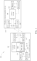
- FIG. 1 is a diagram illustrating one wireless communication system that supports phase feedback (e.g., mmWave phase feedback) according to an embodiment of the present invention.
- the wireless communication system 100 includes a plurality of wireless communication devices 102 and 104.
- the wireless communication system 100 may be any wireless system that supports wireless sensing, such as a Wi-Fi system that supports Wi-Fi sensing and includes an access point (AP) and a non-AP station (STA).
- AP access point
- STA non-AP station
- the wireless communication device 102 may be an AP
- the wireless communication device 104 may be a non-AP STA.
- the wireless communication device 102 may be a non-AP STA
- the wireless communication device 104 may be an AP.
- both of the wireless communication devices 102 and 104 support wireless sensing (also known as WLAN sensing), and can use physical layer (PHY) and/or medium access control (MAC) layer to obtain measurements that might be useful to estimate features such as range, velocity, and motion of objects in an area of interest.
- wireless sensing also known as WLAN sensing
- PHY physical layer
- MAC medium access control
- one of the wireless communication devices 102 and 104 may act as a sensing initiator that initiates a sensing procedure (or DMG sensing procedure) by transmitting a request frame
- the other of the wireless communication devices 102 and 104 may act as a sensing responder that participates in the sensing procedure (or DMG sensing procedure) by responding to the sensing initiator.
- the wireless communication device 102 is a sensing initiator
- the wireless communication device 104 is a sensing responder.
- the wireless communication system 100 is allowed to have more than two wireless communication devices, including an AP and more than one non-AP STA in the same basic service set (BSS).
- BSS basic service set
- the wireless communication devices 102 and 104 may have the same or similar circuit structure.
- the wireless communication device 102 includes a processor 112, a memory 114, a control circuit 116, and a wireless communication circuit 117, where the wireless communication circuit 117 includes a transmitter (TX) circuit 118 and a receiver (RX) circuit 120.
- the memory 114 is arranged to store a program code.
- the processor 112 is arranged to load and execute the program code to manage the wireless communication device 102.
- the control circuit 116 is arranged to control wireless communications with the wireless communication device 104.
- the control circuit 116 controls the TX circuit 118 of the wireless communication circuit 117 to deal with downlink (DL) traffic between AP and non-AP STA, and controls the RX circuit 120 of the wireless communication circuit 118 to deal with uplink (UL) traffic between AP and non-AP STA.
- DL downlink
- UL uplink
- the control circuit 116 controls the TX circuit 118 of the wireless communication circuit 117 to deal with UL traffic between AP and non-AP STA, and controls the RX circuit 120 of the wireless communication circuit 118 to deal with DL traffic between AP and non-AP STA.
- the wireless communication device 104 includes a processor 122, a memory 124, a control circuit 126, and a wireless communication circuit 127, where the wireless communication circuit 127 includes a TX circuit 128 and an RX circuit 130.
- the memory 124 is arranged to store a program code.
- the processor 122 is arranged to load and execute the program code to manage the wireless communication device 104.
- the control circuit 126 is arranged to control wireless communications with the wireless communication device 102.
- the control circuit 126 controls the TX circuit 128 of the wireless communication circuit 127 to deal with UL traffic between AP and non-AP STA, and controls the RX circuit 130 of the wireless communication circuit 127 to deal with DL traffic between AP and non-AP STA.
- the control circuit 126 controls the TX circuit 128 of the wireless communication circuit 127 to deal with DL traffic between AP and non-AP STA, and controls the RX circuit 130 of the wireless communication circuit 127 to deal with UL traffic between AP and non-AP STA.
- the wireless communication device 102 may include additional components to achieve designated functions, and/or the wireless communication device 104 may include additional components to achieve designated functions.
- the wireless communication device 102 (which acts as the sensing initiator) supports the proposed phase report request signaling function.
- the control circuit 116 of the wireless communication device 102 is arranged to generate a measurement request frame (labeled by "REQ") 132, and instruct the wireless communication circuit 117 (particularly, TX circuit 118 of wireless communication circuit 117) to send the measurement request frame 132 to the wireless communication device 104 (which acts as the sensing responder).
- the measurement request frame 132 is configured to carry indication information PH_REQ for phase report from the sensing responder.
- the indication information PH_REQ is signaled via the measurement request frame 132, and is used to indicate that the sensing initiator requests phase information to be included in a measurement report.
- the wireless communication device 102 (which acts as the sensing initiator) initiates a DMG sensing procedure, and the wireless communication device 104 (which acts as the sensing responder) participates in the DMG sensing procedure.
- the measurement request frame 132 includes a DMG Sensing Measurement Session element, and the indication information PH_REQ for phase report is carried in the DMG Sensing Measurement Session element.
- the DMG Sensing Measurement Session element may have a format as illustrate in the following table. Table 1 Element ID Length Element ID Extension Measurement Session Control Report Type Control LCI Octets: 1 1 1 2 1 0 or 16 Peer Orientation Optional Subelements Octets: 0-5 variable
- the indication information PH_REQ for phase report is carried in the Report Type Control field in the DMG Sensing Measurement Session element.
- the Report Type Control field is used to indicate which type of report the sensing initiator expects from the sensing responder.
- the indication information PH_REQ for phase report is carried in a Report Type subfield in the Report Type Control field, where the Report Type subfield may be defined by the following table and may include options with phase, such as "DMG Sensing Image Direction Power and Phase" and "DMG Sensing Image Range-Direction Power and Phase".
- Table 2 Value Description 0 No report 1 CSI 2 DMG Sensing Image Direction Power 3 DMG Sensing Image Range-Doppler Power 4 DMG Sensing Image Range-Direction Power 5 DMG Sensing Image Doppler-Direction Power 6 DMG Sensing Image Range-Doppler Direction Power 7 DMG Sensing Image Direction Power and Phase 8 DMG Sensing Image Range-Direction Power and Phase 9 Target 10-255 Reserved
- the DMG Sensing Measurement Session element includes a plurality of fields.
- the indication information PH_REQ of phase report may be carried by a one-bit subfield included in one of the fields in the DMG Sensing Measurement Session element.
- the indication information PH_REQ for phase report is carried in a one-bit Report Phase subfield in a Report Type Control field.
- the one-bit Report Phase subfield indicates that the sensing initiator requests phase information to be included in the report. The same objective of indicating that the sensing initiator requests phase information to be included in a measurement report is achieved.
- FIG. 2 is a diagram illustrating another wireless communication system that supports phase feedback (e.g., mmWave phase feedback) according to an embodiment of the present invention.
- the wireless communication system 200 includes a plurality of wireless communication devices 202 and 204.
- the wireless communication system 200 may be any wireless system that supports wireless sensing, such as a Wi-Fi system that supports Wi-Fi sensing and includes an AP and a non-AP STA.
- the wireless communication device 202 may be an AP
- the wireless communication device 204 may be a non-AP STA.
- the wireless communication device 202 may be a non-AP STA
- the wireless communication device 204 may be an AP.
- the wireless communication system 200 is allowed to have more than two wireless communication devices, including an AP and more than one non-AP STA in the same BSS.
- the wireless communication device 202 may include additional components to achieve designated functions, and/or the wireless communication device 204 may include additional components to achieve designated functions.
- both of the wireless communication devices 202 and 204 support wireless sensing (also known as WLAN sensing), and can use PHY layer and/or MAC layer to obtain measurements that might be useful to estimate features such as range, velocity, and motion of objects in an area of interest.
- wireless sensing also known as WLAN sensing
- one of the wireless communication devices 202 and 204 may act as a sensing initiator that initiates a sensing procedure (or DMG sensing procedure) by transmitting a request frame
- the other of the wireless communication devices 202 and 204 may act as a sensing responder that participates in the sensing procedure (or DMG sensing procedure) by responding to the sensing initiator.
- the wireless communication device 202 is a sensing initiator
- the wireless communication device 204 is a sensing responder.
- the wireless communication device 204 (which acts as the sensing responder) supports the proposed phase report function.
- the control circuit 208 of the wireless communication device 204 is arranged to generate a measurement report frame (labeled by "REP") 210, and instruct the wireless communication circuit 127 (particularly, TX circuit 128 of wireless communication circuit 127) to send the measurement report frame 210 to the wireless communication device 202 (which acts as the sensing initiator).
- the measurement report frame 210 is configured to carry phase information INF_PH.
- the phase information INF_PH is derived from wireless signal measurements (e.g., Wi-Fi signal measurements) performed at the wireless communication device 204.
- the control circuit 206 of the wireless communication device 202 may be implemented by the control circuit 116 shown in FIG.
- the control circuit 206 of the wireless communication device 202 supports the proposed phase report request signaling function, and sends the measurement request frame 132 to the wireless communication device 204.
- the wireless communication device 204 sends the measurement report frame 210, including the requested phase information INF _PH, to the sensing initiator.
- the measurement request frame 132 may be further configured to carry an indicator IND_PH for indicating presence of the phase information INF PH.
- the wireless communication device 202 (which acts as the sensing initiator) initiates a DMG sensing procedure, and the wireless communication device 204 (which acts as the sensing responder) participates in the DMG sensing procedure.
- the measurement report frame 210 includes a DMG Sensing Report element, and the phase information INF_PH and the associated indicator IND_PH are carried in the DMG Sensing Report element.
- the DMG Sensing Report element may have a format as illustrate in the following table.
- the phase information INF_PH and the associated indicator IND_PH are carried in the DMG Sensing Report field in the DMG Sensing Report element.
- the DMG Sensing Report field may contain one or more subelements.
- the phase report is a part of an image report.
- the DMG Sensing Report field includes a DMG Sensing Image Report Data subelement, and the phase information INF_PH and the associated indicator IND_PH are carried in the DMG Sensing Image Report Data subelement.
- the DMG Sensing Image Report Data subelement may have a format as illustrate in the following table.
- the phase information INF_PH is carried in the Reflection Fields field, and the indicator IND_PH is carried in the Axis Present field.
- the Axis Present field may have a format as illustrate in the following table. Table 5 Range Axis Present Doppler Axis Present Receiver Beam Index Present Transmitter Beam Index Present Phase Present Receive Azimuth Present Receive Elevation Present Receive Direction Reference Bits: 1 1 1 1 1 1 1 1 1
- the Phase Present field in the Axis Present field represents the indicator IND_PH, and can be set to indicate the presence of phase information in the Reflection Fields field.
- the Reflection Fields field may contain multiple Reflection fields. All Reflection fields within a Reflection Fields field have the same format, which can be derived from the Axis Present field.
- the reflection field format for 2 axes, the reflection field format for 3 axes, the reflection field format for 4 axes, and the reflection field format for 5 axes are illustrated in the following tables, respectively.
- Table 6 Axis #1 Axis #2 Reflection Power Reflection Phase Table 7 Axis #1 Axis #2 Axis #3 Reflection Power Reflection Phase Table 8 Axis #1 Axis #2 Axis #3 Axis #4 Reflection Power Reflection Phase Table 9 Axis #1 Axis #2 Axis #3 Axis #4 Axis #5 Reflection Power Reflection Phase
- the Reflection Phase field in the Reflection field represents the phase information INF_PH reported by the sensing responder.
- DMG Sensing Report may be used to carry a report of any DMG-related sensing procedure.
- an EDMG device is also a DMG device.
- the proposed phase feedback design can be applied to DMG sensing reporting and EDMG sensing reporting.
Landscapes
- Engineering & Computer Science (AREA)
- Signal Processing (AREA)
- Computer Networks & Wireless Communication (AREA)
- Computer Security & Cryptography (AREA)
- Mobile Radio Communication Systems (AREA)
- Arrangements For Transmission Of Measured Signals (AREA)
Abstract
Description
- The present invention relates to wireless communications, and more particularly, to a wireless sensing (e.g., Wi-Fi sensing) method for requesting a phase report from a sensing responder and sending the requested phase report to a sensing initiator that requests the phase report and a related wireless communication device.
- With recent advancements, the wireless local area network (WLAN) or wireless fidelity (Wi-Fi) technology has been successfully utilized to realize sensing functionalities such as detection, localization, and recognition. However, the WLAN standards are developed mainly for the purpose of communications, and thus may not be able to meet the stringent sensing requirements. To resolve this issue, a new Task Group (TG), namely IEEE 802.11bf, has been established by the IEEE 802.11 working group, with the objective of creating a new amendment to the WLAN standard to provide advanced sensing requirements while minimizing the effect on communications.
- Wireless sensing, also known as WLAN sensing, is a technology that uses wireless signals (e.g., Wi-Fi signals) to perform sensing tasks, by exploiting prevalent wireless infrastructures and ubiquitous wireless signals over surrounding environments. In particular, wireless radio waves can bounce, penetrate, and bend on the surface of objects during their propagation. By proper signal processing, the received wireless signals can be used to sense surrounding environments, detect obstructions, and interpret target movement. For example, vital signs detection is one of the wireless sensing applications for achieving remote diagnostics measurements. For example, using a millimetre wave (mmWave) Frequency Modulated Continuous Wave (FMCW) radar to monitor human vital signs is a well-known technique. IEEE 802.11bf supports the 60GHz band sensing by improving and modifying the directional multi-gigabit (DMG) implementation and the enhanced DMG (EDMG) implementation. The magnitude of range-Doppler map can be used to obtain information about speed and distance, but is unable to provide information about a small distance variation such as vibration resulting from breathing/heartbeat. Thus, there is a need for wireless sensing (e.g., Wi-Fi sensing) to support feedback of the phase of range-Doppler map for vital signs detection (e.g., breathing rate/heartbeat rate).
- This in mind, the present invention aims at providing a wireless sensing (e.g., Wi-Fi sensing) method for requesting a phase report from a sensing responder and sending the requested phase report to a sensing initiator that requests the phase report and a related wireless communication device.
- This is achieved by wireless sensing method and wireless communication device according to independent claims. The dependent claims pertain to corresponding further developments and improvements.
- As will be seen more clearly from the detailed description following below, one claimed wireless sensing method includes: generating a measurement request frame, wherein the measurement request frame is configured to carry indication information for phase report from a sensing responder; and sending the measurement request frame to the sensing responder.
- Another claimed wireless sensing method includes: generating a measurement report frame, wherein the measurement report frame is configured to carry phase information; and sending the measurement report frame to a sensing initiator.
- One claimed wireless communication device for wireless sensing includes a wireless communication circuit and a control circuit. The control circuit is arranged to generate a measurement request frame, and instruct the wireless communication circuit to send the measurement request frame to a sensing responder, wherein the measurement request frame is configured to carry indication information for phase report from the sensing responder.
- In the following, the invention is further illustrated by way of example, taking reference to the accompanying drawings. Thereof
-
FIG. 1 is a diagram illustrating one wireless communication system that supports phase feedback (e.g., mmWave phase feedback) according to an embodiment of the present invention, and -
FIG. 2 is a diagram illustrating another wireless communication system that supports phase feedback (e.g., mmWave phase feedback) according to an embodiment of the present invention. - Certain terms are used throughout the following description and claims, which refer to particular components. As one skilled in the art will appreciate, electronic equipment manufacturers may refer to a component by different names. This document does not intend to distinguish between components that differ in name but not in function. In the following description and in the claims, the terms "include" and "comprise" are used in an open-ended fashion, and thus should be interpreted to mean "include, but not limited to ...". Also, the term "couple" is intended to mean either an indirect or direct electrical connection. Accordingly, if one device is coupled to another device, that connection may be through a direct electrical connection, or through an indirect electrical connection via other devices and connections.
-
FIG. 1 is a diagram illustrating one wireless communication system that supports phase feedback (e.g., mmWave phase feedback) according to an embodiment of the present invention. Thewireless communication system 100 includes a plurality ofwireless communication devices wireless communication system 100 may be any wireless system that supports wireless sensing, such as a Wi-Fi system that supports Wi-Fi sensing and includes an access point (AP) and a non-AP station (STA). For example, thewireless communication device 102 may be an AP, and thewireless communication device 104 may be a non-AP STA. For another example, thewireless communication device 102 may be a non-AP STA, and thewireless communication device 104 may be an AP. In this embodiment, both of thewireless communication devices wireless communication devices wireless communication devices wireless communication device 102 is a sensing initiator, and thewireless communication device 104 is a sensing responder. - For brevity and simplicity, only two
wireless communication devices FIG. 1 . In practice, thewireless communication system 100 is allowed to have more than two wireless communication devices, including an AP and more than one non-AP STA in the same basic service set (BSS). - The
wireless communication devices FIG. 1 , thewireless communication device 102 includes aprocessor 112, amemory 114, acontrol circuit 116, and awireless communication circuit 117, where thewireless communication circuit 117 includes a transmitter (TX)circuit 118 and a receiver (RX)circuit 120. Thememory 114 is arranged to store a program code. Theprocessor 112 is arranged to load and execute the program code to manage thewireless communication device 102. Thecontrol circuit 116 is arranged to control wireless communications with thewireless communication device 104. In a case where thewireless communication device 102 is an AP and thewireless communication device 104 is a non-AP, thecontrol circuit 116 controls theTX circuit 118 of thewireless communication circuit 117 to deal with downlink (DL) traffic between AP and non-AP STA, and controls theRX circuit 120 of thewireless communication circuit 118 to deal with uplink (UL) traffic between AP and non-AP STA. In another case where thewireless communication device 102 is a non-AP STA and thewireless communication device 104 is an AP, thecontrol circuit 116 controls theTX circuit 118 of thewireless communication circuit 117 to deal with UL traffic between AP and non-AP STA, and controls theRX circuit 120 of thewireless communication circuit 118 to deal with DL traffic between AP and non-AP STA. - The
wireless communication device 104 includes aprocessor 122, amemory 124, acontrol circuit 126, and awireless communication circuit 127, where thewireless communication circuit 127 includes aTX circuit 128 and anRX circuit 130. Thememory 124 is arranged to store a program code. Theprocessor 122 is arranged to load and execute the program code to manage thewireless communication device 104. Thecontrol circuit 126 is arranged to control wireless communications with thewireless communication device 102. In a case where thewireless communication device 102 is an AP and thewireless communication device 104 is a non-AP STA, thecontrol circuit 126 controls theTX circuit 128 of thewireless communication circuit 127 to deal with UL traffic between AP and non-AP STA, and controls theRX circuit 130 of thewireless communication circuit 127 to deal with DL traffic between AP and non-AP STA. In another case where thewireless communication device 102 is a non-AP STA and thewireless communication device 104 is an AP, thecontrol circuit 126 controls theTX circuit 128 of thewireless communication circuit 127 to deal with DL traffic between AP and non-AP STA, and controls theRX circuit 130 of thewireless communication circuit 127 to deal with UL traffic between AP and non-AP STA. - It should be noted that only the components pertinent to the present invention are illustrated in
FIG. 1 . In practice, thewireless communication device 102 may include additional components to achieve designated functions, and/or thewireless communication device 104 may include additional components to achieve designated functions. - In this embodiment, the wireless communication device 102 (which acts as the sensing initiator) supports the proposed phase report request signaling function. Hence, the
control circuit 116 of thewireless communication device 102 is arranged to generate a measurement request frame (labeled by "REQ") 132, and instruct the wireless communication circuit 117 (particularly,TX circuit 118 of wireless communication circuit 117) to send themeasurement request frame 132 to the wireless communication device 104 (which acts as the sensing responder). Themeasurement request frame 132 is configured to carry indication information PH_REQ for phase report from the sensing responder. Specifically, the indication information PH_REQ is signaled via themeasurement request frame 132, and is used to indicate that the sensing initiator requests phase information to be included in a measurement report. - For example, the wireless communication device 102 (which acts as the sensing initiator) initiates a DMG sensing procedure, and the wireless communication device 104 (which acts as the sensing responder) participates in the DMG sensing procedure. The
measurement request frame 132 includes a DMG Sensing Measurement Session element, and the indication information PH_REQ for phase report is carried in the DMG Sensing Measurement Session element. The DMG Sensing Measurement Session element may have a format as illustrate in the following table.Table 1 Element ID Length Element ID Extension Measurement Session Control Report Type Control LCI Octets: 1 1 1 2 1 0 or 16 Peer Orientation Optional Subelements Octets: 0-5 variable - In some embodiments of the present invention, the indication information PH_REQ for phase report is carried in the Report Type Control field in the DMG Sensing Measurement Session element. The Report Type Control field is used to indicate which type of report the sensing initiator expects from the sensing responder.
- For example, the indication information PH_REQ for phase report is carried in a Report Type subfield in the Report Type Control field, where the Report Type subfield may be defined by the following table and may include options with phase, such as "DMG Sensing Image Direction Power and Phase" and "DMG Sensing Image Range-Direction Power and Phase".
Table 2 Value Description 0 No report 1 CSI 2 DMG Sensing Image Direction Power 3 DMG Sensing Image Range-Doppler Power 4 DMG Sensing Image Range-Direction Power 5 DMG Sensing Image Doppler-Direction Power 6 DMG Sensing Image Range-Doppler Direction Power 7 DMG Sensing Image Direction Power and Phase 8 DMG Sensing Image Range-Direction Power and Phase 9 Target 10-255 Reserved - As illustrated in Table 1, the DMG Sensing Measurement Session element includes a plurality of fields. In an alternative signaling design, the indication information PH_REQ of phase report may be carried by a one-bit subfield included in one of the fields in the DMG Sensing Measurement Session element. For example, the indication information PH_REQ for phase report is carried in a one-bit Report Phase subfield in a Report Type Control field. The one-bit Report Phase subfield indicates that the sensing initiator requests phase information to be included in the report. The same objective of indicating that the sensing initiator requests phase information to be included in a measurement report is achieved.
-
FIG. 2 is a diagram illustrating another wireless communication system that supports phase feedback (e.g., mmWave phase feedback) according to an embodiment of the present invention. Thewireless communication system 200 includes a plurality ofwireless communication devices wireless communication system 200 may be any wireless system that supports wireless sensing, such as a Wi-Fi system that supports Wi-Fi sensing and includes an AP and a non-AP STA. For example, thewireless communication device 202 may be an AP, and thewireless communication device 204 may be a non-AP STA. For another example, thewireless communication device 202 may be a non-AP STA, and thewireless communication device 204 may be an AP. For brevity and simplicity, only twowireless communication devices FIG. 2 . In practice, thewireless communication system 200 is allowed to have more than two wireless communication devices, including an AP and more than one non-AP STA in the same BSS. - It should be noted that only the components pertinent to the present invention are illustrated in
FIG. 2 . In practice, thewireless communication device 202 may include additional components to achieve designated functions, and/or thewireless communication device 204 may include additional components to achieve designated functions. - In this embodiment, both of the
wireless communication devices wireless communication devices wireless communication devices wireless communication device 202 is a sensing initiator, and thewireless communication device 204 is a sensing responder. - In this embodiment, the wireless communication device 204 (which acts as the sensing responder) supports the proposed phase report function. Hence, the
control circuit 208 of thewireless communication device 204 is arranged to generate a measurement report frame (labeled by "REP") 210, and instruct the wireless communication circuit 127 (particularly,TX circuit 128 of wireless communication circuit 127) to send themeasurement report frame 210 to the wireless communication device 202 (which acts as the sensing initiator). Themeasurement report frame 210 is configured to carry phase information INF_PH. For example, the phase information INF_PH is derived from wireless signal measurements (e.g., Wi-Fi signal measurements) performed at thewireless communication device 204. Thecontrol circuit 206 of thewireless communication device 202 may be implemented by thecontrol circuit 116 shown inFIG. 1 . Hence, thecontrol circuit 206 of thewireless communication device 202 supports the proposed phase report request signaling function, and sends themeasurement request frame 132 to thewireless communication device 204. In response to the indication information PH_REQ for phase report, thewireless communication device 204 sends themeasurement report frame 210, including the requested phase information INF _PH, to the sensing initiator. In some embodiments of the present invention, themeasurement request frame 132 may be further configured to carry an indicator IND_PH for indicating presence of the phase information INF PH. - For example, the wireless communication device 202 (which acts as the sensing initiator) initiates a DMG sensing procedure, and the wireless communication device 204 (which acts as the sensing responder) participates in the DMG sensing procedure. The
measurement report frame 210 includes a DMG Sensing Report element, and the phase information INF_PH and the associated indicator IND_PH are carried in the DMG Sensing Report element. The DMG Sensing Report element may have a format as illustrate in the following table.Table 3 Element ID Length Element ID Extension DMG Measurement Session ID Measure-ment Burst ID Sensing Instance SN Octets: 1 1 1 1 1 1 DMG Sensing DMG Sensing DMG Sensing Report Type Report Control Report Octets: 1 4 Variable - In some embodiments of the present invention, the phase information INF_PH and the associated indicator IND_PH are carried in the DMG Sensing Report field in the DMG Sensing Report element. The DMG Sensing Report field may contain one or more subelements. For example, the phase report is a part of an image report. The DMG Sensing Report field includes a DMG Sensing Image Report Data subelement, and the phase information INF_PH and the associated indicator IND_PH are carried in the DMG Sensing Image Report Data subelement. The DMG Sensing Image Report Data subelement may have a format as illustrate in the following table.
Table 4 Subelement ID Length Data Block SN Axis Present Reflection Power Bias Reflection Power Slope Octets: 1 1 1 1 1 1 Number of Reflection Fields Reflection Fields Reserved Octets: 3 variable Variable - In some embodiments of the present invention, the phase information INF_PH is carried in the Reflection Fields field, and the indicator IND_PH is carried in the Axis Present field. The Axis Present field may have a format as illustrate in the following table.
Table 5 Range Axis Present Doppler Axis Present Receiver Beam Index Present Transmitter Beam Index Present Phase Present Receive Azimuth Present Receive Elevation Present Receive Direction Reference Bits: 1 1 1 1 1 1 1 1 - The Phase Present field in the Axis Present field represents the indicator IND_PH, and can be set to indicate the presence of phase information in the Reflection Fields field.
- The Reflection Fields field may contain multiple Reflection fields. All Reflection fields within a Reflection Fields field have the same format, which can be derived from the Axis Present field. The reflection field format for 2 axes, the reflection field format for 3 axes, the reflection field format for 4 axes, and the reflection field format for 5 axes are illustrated in the following tables, respectively.
Table 6: Axis #1 Axis # 2Reflection Power Reflection Phase Table 7 Axis #1 Axis # 2Axis #3 Reflection Power Reflection Phase Table 8 Axis #1 Axis # 2Axis #3 Axis #4 Reflection Power Reflection Phase Table 9 Axis #1 Axis # 2Axis #3 Axis #4 Axis #5 Reflection Power Reflection Phase - The Reflection Phase field in the Reflection field represents the phase information INF_PH reported by the sensing responder.
- It should be noted that "DMG Sensing Report" may be used to carry a report of any DMG-related sensing procedure. For example, an EDMG device is also a DMG device. Hence, the proposed phase feedback design can be applied to DMG sensing reporting and EDMG sensing reporting.
Claims (15)
- A wireless sensing method characterized by:generating a measurement request frame (REQ), wherein the measurement request frame (REQ) is configured to carry indication information (PH_REQ) for phase report from a sensing responder (104, 204); andsending the measurement request frame (REQ) to the sensing responder (104, 204).
- The wireless sensing method of claim 1, characterized in that the measurement request frame (REQ) comprises a directional multi-gigabit, hereinafter referred to as DMG, Sensing Measurement Session element, and the indication information (PH_REQ) for phase report is carried in the DMG Sensing Measurement Session element.
- The wireless sensing method of claim 2, characterized in that the DMG Sensing Measurement Session element comprises a Report Type Control field, the Report Type Control field comprises a Report Type subfield, and the indication information (PH_REQ) for phase report is carried in the Report Type subfield.
- The wireless sensing method of claim 2, characterized in that the DMG Sensing Measurement Session element comprises a plurality of fields, and the indication information (PH_REQ) for phase report is carried by a one-bit subfield included in one of the plurality of fields.
- A wireless sensing method characterized by:generating a measurement report frame (REP), wherein the measurement report frame (REP) is configured to carry phase information (INF_PH); andsending the measurement report frame (REP) to a sensing initiator (102, 202).
- The wireless sensing method of claim 5, characterized in that the measurement report frame (REP) comprises a directional multi-gigabit, hereinafter referred to as DMG, Sensing Report element, and the phase information (INF_PH) is carried in the DMG Sensing Report element.
- The wireless sensing method of claim 6, characterized in that the DMG Sensing Report element comprises a DMG Sensing Report field, and the phase information (INF_PH) is carried in the DMG Sensing Report field.
- The wireless sensing method of claim 7, characterized in that the DMG Sensing Report field comprises a DMG Sensing Image Report Data subelement, the DMG Sensing Image Report Data subelement comprises a Reflection Fields field, the Reflection Fields field comprises a Reflection field with a Reflection Phase field, and the phase information (INF_PH) is carried in the Reflection Phase field.
- The wireless sensing method of claim 5, characterized in that the measurement report frame (REP) is further configured to carry an indicator (IND_PH) for indicating presence of the phase information (INF_PH).
- The wireless sensing method of claim 9, characterized in that the measurement report frame (REP) comprises a directional multi-gigabit, hereinafter referred to as DMG, Sensing Report element, and the indicator (IND _PH) is carried in the DMG Sensing Report element.
- The wireless sensing method of claim 10, characterized in that the DMG Sensing Report element comprises a DMG Sensing Report field, and the indicator (IND _PH) is carried in the DMG Sensing Report field.
- The wireless sensing method of claim 11, characterized in that the DMG Sensing Report field comprises a DMG Sensing Image Report Data subelement, the DMG Sensing Image Report Data subelement comprises an Axis Present field, the Axis Present field comprises a Phase Present field, and the indicator (IND _PH) is carried in the Phase Present field.
- The wireless sensing method of claim 5, characterized in that the measurement report frame is sent during a directional multi-gigabit sensing procedure or a Wi-Fi sensing procedure.
- A wireless communication device (102, 202) for wireless sensing, characterized by:a wireless communication circuit (117); anda control circuit (116, 206), arranged to generate a measurement request frame (REQ), and instruct the wireless communication circuit (117) to send the measurement request frame (REQ) to a sensing responder (104, 204), wherein the measurement request frame (REQ) is configured to carry indication information (PH_REQ) for phase report from the sensing responder (104, 204).
- The wireless sensing method of claim 1 or the wireless communication device (102, 202) of claim 14, characterized in that the measurement request frame (REQ) is sent during a directional multi-gigabit sensing procedure or a Wi-Fi sensing procedure.
Applications Claiming Priority (4)
| Application Number | Priority Date | Filing Date | Title |
|---|---|---|---|
| US202263382552P | 2022-11-07 | 2022-11-07 | |
| US202263476986P | 2022-12-23 | 2022-12-23 | |
| US202363479748P | 2023-01-13 | 2023-01-13 | |
| US18/501,047 US20240155402A1 (en) | 2022-11-07 | 2023-11-03 | Wireless sensing method for requesting phase report from sensing responder and sending requested phase report to sensing initiator and related wireless communication device |
Publications (1)
| Publication Number | Publication Date |
|---|---|
| EP4366370A1 true EP4366370A1 (en) | 2024-05-08 |
Family
ID=88697618
Family Applications (1)
| Application Number | Title | Priority Date | Filing Date |
|---|---|---|---|
| EP23207852.7A Pending EP4366370A1 (en) | 2022-11-07 | 2023-11-06 | Wireless sensing method for requesting phase report from sensing responder and sending requested phase report to sensing initiator and related wireless communication device |
Country Status (3)
| Country | Link |
|---|---|
| US (1) | US20240155402A1 (en) |
| EP (1) | EP4366370A1 (en) |
| TW (1) | TW202420867A (en) |
Citations (2)
| Publication number | Priority date | Publication date | Assignee | Title |
|---|---|---|---|---|
| US20220304051A1 (en) * | 2021-03-19 | 2022-09-22 | Huawei Technologies Co., Ltd. | Method and system for wi-fi sensing |
| US20220322116A1 (en) * | 2021-04-06 | 2022-10-06 | Huawei Technologies Co., Ltd. | Method, apparatus and system for communicating wi-fi sensing measurements and feedback |
-
2023
- 2023-11-03 US US18/501,047 patent/US20240155402A1/en active Pending
- 2023-11-06 TW TW112142587A patent/TW202420867A/en unknown
- 2023-11-06 EP EP23207852.7A patent/EP4366370A1/en active Pending
Patent Citations (2)
| Publication number | Priority date | Publication date | Assignee | Title |
|---|---|---|---|---|
| US20220304051A1 (en) * | 2021-03-19 | 2022-09-22 | Huawei Technologies Co., Ltd. | Method and system for wi-fi sensing |
| US20220322116A1 (en) * | 2021-04-06 | 2022-10-06 | Huawei Technologies Co., Ltd. | Method, apparatus and system for communicating wi-fi sensing measurements and feedback |
Non-Patent Citations (2)
| Title |
|---|
| 802 11 WORKING GROUP OF THE LAN/MAN STANDARDS COMMITTEE OF THE IEEE COMPUTER SOCIETY: "Draft Standard for Information technology- Tele - communications and information exchange between systems Local and metropolitan area networks- Specific requirements Part 11: Wireless LAN Medium Access Control (MAC) and Physical Layer (PHY) Specifications Amendment 2: Enhancements for Wireless LAN S", vol. 802.11bf drafts, no. D0.3, 13 September 2022 (2022-09-13), pages 1 - 120, XP068192331, Retrieved from the Internet <URL:https://grouper.ieee.org/groups/802/11/private/Draft_Standards/11bf/Draft%20P802.11bf_D0.3.pdf> [retrieved on 20220913] * |
| CLAUDIO DA SILVA (META PLATFORMS ET AL: "Specification Framework for TGbf", vol. 802.11bf, no. 7, 24 January 2022 (2022-01-24), pages 1 - 21, XP068188659, Retrieved from the Internet <URL:https://mentor.ieee.org/802.11/dcn/21/11-21-0504-07-00bf-specification-framework-for-tgbf.docx> [retrieved on 20220124] * |
Also Published As
| Publication number | Publication date |
|---|---|
| TW202420867A (en) | 2024-05-16 |
| US20240155402A1 (en) | 2024-05-09 |
Similar Documents
| Publication | Publication Date | Title |
|---|---|---|
| US12041572B2 (en) | Method and device for user equipment positioning | |
| US12549240B2 (en) | Apparatus and methods for determining line of sight (LOS) from intensity measurements | |
| US11917494B2 (en) | Positioning method and apparatus | |
| US8340693B2 (en) | WiMAX base station and method for determining location information for a mobile station in a WiMAX network | |
| US12176986B2 (en) | Apparatus, method and computer program for beam management | |
| US12490223B2 (en) | Method for transmitting and receiving signal in wireless communication system, and apparatus supporting same | |
| CN111837355A (en) | RSRP reporting method for downlink positioning based on NR high resolution angle | |
| US12405342B2 (en) | Method of transmitting and receiving information for measurement of PRS in wireless communication system and apparatus therefor | |
| EP2582068A2 (en) | Beamforming training within a wireless communication system utilizing a directional antenna | |
| EP3908846A1 (en) | Method and device for positioning utilizing beam information | |
| CN113228760B (en) | Positioning with multiple access points | |
| US20240224219A1 (en) | Method and device for positioning in wireless communication system | |
| CN112135343B (en) | Use of ranging technology for ultra-wideband communications in millimeter wave communication systems | |
| WO2020156470A1 (en) | Communication method and apparatus | |
| US6487423B1 (en) | Method and an arrangement in a mobile radio system | |
| US20230328680A1 (en) | Method for transmitting and receiving signal in wireless communication system, and apparatus supporting same | |
| KR20020013813A (en) | Location based adaptive antenna scheme for wireless data applications | |
| US20230275639A1 (en) | Precoding Method and Communication Apparatus | |
| US20220330041A1 (en) | Method for angle based positioning measurement and apparatus therefor | |
| GB2631173A (en) | Sidelink anchor device management | |
| CN111869123B (en) | Communication device for efficient beam management | |
| US20240155402A1 (en) | Wireless sensing method for requesting phase report from sensing responder and sending requested phase report to sensing initiator and related wireless communication device | |
| CN117982120A (en) | Wireless sensing method and wireless communication device for performing wireless sensing | |
| US20180115914A1 (en) | Communication system, communication device and method | |
| KR100516536B1 (en) | Method for data transmission with double tx antennas in turn of forward link |
Legal Events
| Date | Code | Title | Description |
|---|---|---|---|
| PUAI | Public reference made under article 153(3) epc to a published international application that has entered the european phase |
Free format text: ORIGINAL CODE: 0009012 |
|
| STAA | Information on the status of an ep patent application or granted ep patent |
Free format text: STATUS: THE APPLICATION HAS BEEN PUBLISHED |
|
| AK | Designated contracting states |
Kind code of ref document: A1 Designated state(s): AL AT BE BG CH CY CZ DE DK EE ES FI FR GB GR HR HU IE IS IT LI LT LU LV MC ME MK MT NL NO PL PT RO RS SE SI SK SM TR |
|
| STAA | Information on the status of an ep patent application or granted ep patent |
Free format text: STATUS: REQUEST FOR EXAMINATION WAS MADE |
|
| 17P | Request for examination filed |
Effective date: 20241107 |
|
| RBV | Designated contracting states (corrected) |
Designated state(s): AL AT BE BG CH CY CZ DE DK EE ES FI FR GB GR HR HU IE IS IT LI LT LU LV MC ME MK MT NL NO PL PT RO RS SE SI SK SM TR |