EP4366093A1 - Pv terminal assembly and electrical device - Google Patents
Pv terminal assembly and electrical device Download PDFInfo
- Publication number
- EP4366093A1 EP4366093A1 EP22882289.6A EP22882289A EP4366093A1 EP 4366093 A1 EP4366093 A1 EP 4366093A1 EP 22882289 A EP22882289 A EP 22882289A EP 4366093 A1 EP4366093 A1 EP 4366093A1
- Authority
- EP
- European Patent Office
- Prior art keywords
- terminal
- mounting frame
- terminals
- input port
- sensor
- Prior art date
- Legal status (The legal status is an assumption and is not a legal conclusion. Google has not performed a legal analysis and makes no representation as to the accuracy of the status listed.)
- Pending
Links
Images



Classifications
-
- H—ELECTRICITY
- H01—ELECTRIC ELEMENTS
- H01R—ELECTRICALLY-CONDUCTIVE CONNECTIONS; STRUCTURAL ASSOCIATIONS OF A PLURALITY OF MUTUALLY-INSULATED ELECTRICAL CONNECTING ELEMENTS; COUPLING DEVICES; CURRENT COLLECTORS
- H01R9/00—Structural associations of a plurality of mutually-insulated electrical connecting elements, e.g. terminal strips or terminal blocks; Terminals or binding posts mounted upon a base or in a case; Bases therefor
- H01R9/22—Bases, e.g. strip, block, panel
- H01R9/24—Terminal blocks
- H01R9/26—Clip-on terminal blocks for side-by-side rail- or strip-mounting
- H01R9/2608—Fastening means for mounting on support rail or strip
-
- H—ELECTRICITY
- H01—ELECTRIC ELEMENTS
- H01R—ELECTRICALLY-CONDUCTIVE CONNECTIONS; STRUCTURAL ASSOCIATIONS OF A PLURALITY OF MUTUALLY-INSULATED ELECTRICAL CONNECTING ELEMENTS; COUPLING DEVICES; CURRENT COLLECTORS
- H01R9/00—Structural associations of a plurality of mutually-insulated electrical connecting elements, e.g. terminal strips or terminal blocks; Terminals or binding posts mounted upon a base or in a case; Bases therefor
- H01R9/22—Bases, e.g. strip, block, panel
- H01R9/24—Terminal blocks
- H01R9/26—Clip-on terminal blocks for side-by-side rail- or strip-mounting
- H01R9/2625—Clip-on terminal blocks for side-by-side rail- or strip-mounting with built-in electrical component
- H01R9/2641—Clip-on terminal blocks for side-by-side rail- or strip-mounting with built-in electrical component with built-in overvoltage protection
-
- H—ELECTRICITY
- H02—GENERATION; CONVERSION OR DISTRIBUTION OF ELECTRIC POWER
- H02S—GENERATION OF ELECTRIC POWER BY CONVERSION OF INFRARED RADIATION, VISIBLE LIGHT OR ULTRAVIOLET LIGHT, e.g. USING PHOTOVOLTAIC [PV] MODULES
- H02S40/00—Components or accessories in combination with PV modules, not provided for in groups H02S10/00 - H02S30/00
- H02S40/30—Electrical components
-
- H—ELECTRICITY
- H02—GENERATION; CONVERSION OR DISTRIBUTION OF ELECTRIC POWER
- H02S—GENERATION OF ELECTRIC POWER BY CONVERSION OF INFRARED RADIATION, VISIBLE LIGHT OR ULTRAVIOLET LIGHT, e.g. USING PHOTOVOLTAIC [PV] MODULES
- H02S40/00—Components or accessories in combination with PV modules, not provided for in groups H02S10/00 - H02S30/00
- H02S40/30—Electrical components
- H02S40/34—Electrical components comprising specially adapted electrical connection means to be structurally associated with the PV module, e.g. junction boxes
-
- H—ELECTRICITY
- H05—ELECTRIC TECHNIQUES NOT OTHERWISE PROVIDED FOR
- H05K—PRINTED CIRCUITS; CASINGS OR CONSTRUCTIONAL DETAILS OF ELECTRIC APPARATUS; MANUFACTURE OF ASSEMBLAGES OF ELECTRICAL COMPONENTS
- H05K5/00—Casings, cabinets or drawers for electric apparatus
- H05K5/02—Details
- H05K5/0217—Mechanical details of casings
-
- H—ELECTRICITY
- H05—ELECTRIC TECHNIQUES NOT OTHERWISE PROVIDED FOR
- H05K—PRINTED CIRCUITS; CASINGS OR CONSTRUCTIONAL DETAILS OF ELECTRIC APPARATUS; MANUFACTURE OF ASSEMBLAGES OF ELECTRICAL COMPONENTS
- H05K5/00—Casings, cabinets or drawers for electric apparatus
- H05K5/02—Details
- H05K5/0247—Electrical details of casings, e.g. terminals, passages for cables or wiring
-
- H—ELECTRICITY
- H01—ELECTRIC ELEMENTS
- H01R—ELECTRICALLY-CONDUCTIVE CONNECTIONS; STRUCTURAL ASSOCIATIONS OF A PLURALITY OF MUTUALLY-INSULATED ELECTRICAL CONNECTING ELEMENTS; COUPLING DEVICES; CURRENT COLLECTORS
- H01R12/00—Structural associations of a plurality of mutually-insulated electrical connecting elements, specially adapted for printed circuits, e.g. printed circuit boards [PCB], flat or ribbon cables, or like generally planar structures, e.g. terminal strips, terminal blocks; Coupling devices specially adapted for printed circuits, flat or ribbon cables, or like generally planar structures; Terminals specially adapted for contact with, or insertion into, printed circuits, flat or ribbon cables, or like generally planar structures
- H01R12/50—Fixed connections
- H01R12/51—Fixed connections for rigid printed circuits or like structures
- H01R12/515—Terminal blocks providing connections to wires or cables
-
- H—ELECTRICITY
- H02—GENERATION; CONVERSION OR DISTRIBUTION OF ELECTRIC POWER
- H02G—INSTALLATION OF ELECTRIC CABLES OR LINES, OR OF COMBINED OPTICAL AND ELECTRIC CABLES OR LINES
- H02G3/00—Installations of electric cables or lines or protective tubing therefor in or on buildings, equivalent structures or vehicles
- H02G3/02—Details
- H02G3/08—Distribution boxes; Connection or junction boxes
- H02G3/16—Distribution boxes; Connection or junction boxes structurally associated with support for line-connecting terminals within the box
-
- Y—GENERAL TAGGING OF NEW TECHNOLOGICAL DEVELOPMENTS; GENERAL TAGGING OF CROSS-SECTIONAL TECHNOLOGIES SPANNING OVER SEVERAL SECTIONS OF THE IPC; TECHNICAL SUBJECTS COVERED BY FORMER USPC CROSS-REFERENCE ART COLLECTIONS [XRACs] AND DIGESTS
- Y02—TECHNOLOGIES OR APPLICATIONS FOR MITIGATION OR ADAPTATION AGAINST CLIMATE CHANGE
- Y02E—REDUCTION OF GREENHOUSE GAS [GHG] EMISSIONS, RELATED TO ENERGY GENERATION, TRANSMISSION OR DISTRIBUTION
- Y02E10/00—Energy generation through renewable energy sources
- Y02E10/50—Photovoltaic [PV] energy
Definitions
- the present application relates to the technical field of photovoltaic power generation, and in particular to a PV terminal assembly and an electrical device.
- an electrical device such as an inverter and a combiner box mainly includes: a cabinet, PV terminals, a current detection board, a direct current switch, a printed circuit board and the like, where PV cables are connected to the PV terminals, the PV terminals are connected to the current detection board through the cable, the current detection board is connected to one side of the direct current switch through the cable, and the other side of the direct current switch is connected to the printed circuit board through the cable.
- a side plate of the cabinet is provided with fixing holes for mounting the PV terminals, and the above-mentioned PV terminals are mounted in the fixing holes from outside of the cabinet.
- the fixing holes correspond to the PV terminals respectively, and the number of channels of the PV terminals is settled and unadjustable, resulting in poor extensibility and compatibility of the PV terminals, and smaller application scope of the whole electrical device.
- each of the PV terminals is hermetically connected with the cabinet, and generally the PV terminals are hermetically connected with the cabinet through sealing members.
- a distance between two adjacent fixing holes is large. Therefore, a space occupied by all of the PV terminals is large, and a volume of the whole electrical device is large.
- the technical problem to be solved by those skilled in the art is to design a PV terminal in such a way that the number of channels of the PV terminals is adjustable and thus the extensibility and compatibility are improved.
- an object of the present application is to provide a PV terminal assembly, so that the number of channels of PV terminals is adjustable, and thus the extensibility and compatibility are improved.
- Another object of the present application is to provide an electrical device including the PV terminal assembly as described above.
- a PV terminal assembly includes a mounting frame and at least one PV terminal, where the mounting frame is provided with at least two mounting positions used for fixing the at least one PV terminal.
- the mounting frame is in a strip shape, and any two of the mounting positions are sequentially distributed along a length direction of the mounting frame.
- the PV terminal is detachably fixed to the mounting frame.
- the mounting frame is a guide rail, and the PV terminal clips on the guide rail; or, the mounting frame is a structural member with a mounting hole, and the PV terminal is fixed to the mounting hole through a fastener.
- a PV input port of the PV terminal is a positive PV input port or a negative PV input port, and the number of the PV terminals is even, where at least one of the PV terminals is a positive PV terminal, and at least one of the PV terminals is a negative PV terminal; the positive PV terminals and the negative PV terminals are alternately distributed; or the positive PV terminals are distributed at one end of the mounting frame, and the negative PV terminals are distributed at the other end of the mounting frame.
- the PV input port of the PV terminal includes a positive PV input port and a negative PV input port.
- the PV terminal is integrated with a sensor, and the PV terminal is provided with a sensor signal output port configured for outputting signals collected by the sensor; where the PV terminal is provided with a power input port which is configured for inputting a power supply for supplying power to the sensor; or, the PV terminal is integrated with a power supply circuit which is configured for introducing power from a PV input cable connected to the PV terminal and supplying the power to the sensor.
- the PV terminal is integrated with a terminal-dedicated printed circuit board
- the senor includes a temperature sensor and/or a current sensor and/or a voltage sensor.
- the mounting frame is provided with at least two mounting positions used for fixing the PV terminals, so that at least two PV terminals are integrated on the mounting frame.
- the number of channels of PV terminals of the whole PV terminal assembly can be adjusted by adjusting the number of PV terminals on the mounting frame, thereby improving the extensibility and compatibility, enabling the whole electrical device to be compatible with various input configurations, and improving the development efficiency.
- At least two PV terminals can be integrated on the mounting frame of the PV terminal assembly provided by the present application.
- the mounting frame disclosed herein is directly fixed on the cabinet, which can reduce the space occupied by all of the PV terminals, thereby reducing the volume of the whole electrical device. Further, the mounting of the PV terminal is simplified and the mounting efficiency is improved.
- an electrical device is further provided according to the present application, which includes the PV terminal assembly as described above.
- the electrical device further includes a cabinet and electronic components fixed in the cabinet, where the mounting frame is fixed to the cabinet or the electronic components.
- the cabinet is provided with a via hole for exposing the PV input port of the PV terminal to outside, and the PV terminal assembly is hermetically connected with the via hole.
- the cabinet is provided with a via hole for exposing the PV input port of the PV terminal to outside; and the electrical device further includes a protective cover which is located outside the cabinet and covers the via hole, and the protective cover is hermetically connected with the cabinet and is provided with a wire leading hole for inserting the PV input cable.
- the protective cover is provided with a waterproof ring fixed to the wire leading hole, and the waterproof ring is configured for hermetically connecting the wire leading hole and the PV input cable.
- the wire leading hole is sealed by the waterproof ring, and the waterproof ring is puncturable, so that the PV input cable can puncture and pass through the waterproof ring.
- a PV terminal assembly provided according to an embodiment of the present application includes a mounting frame 100 and at least one PV terminal 200.
- the mounting frame 100 is provided with at least two mounting positions used for fixing the at least one PV terminal 200.
- one mounting position is used for mounting one PV terminal 200, that is, the mounting position is in one-to-one correspondence with the PV terminal 200.
- the number of the above-mentioned PV terminals 200 may be selected based on actual needs, that is, it is applicable that all of the mounting positions are fixed with the PV terminals 200, and it is also applicable that only some of the mounting positions are fixed with the PV terminals 200, and the rest mounting positions are vacant of the PV terminals 200.
- the mounting frame 100 is provided with at least two mounting positions used for fixing the PV terminals 200, so that at least two PV terminals 200 are integrated on the mounting frame 100.
- the number of channels of the whole PV terminal assembly can be adjusted by adjusting the number of PV terminals 200 on the mounting frame 100, thereby improving the extensibility and compatibility, enabling the whole electrical device to be compatible with various input configurations, and improving the development efficiency.
- the mounting frame 100 is directly fixed on a cabinet 300, which can reduce the space occupied by all of the PV terminals 200, thereby reducing the volume of the whole electrical device. Further, the mounting of the PV terminal 200 is simplified and the mounting efficiency is improved.
- the number of the PV terminal 200 is at least two, two adjacent PV terminals 200 are in contact with each other, so as to minimize the space occupied by the PV terminal assembly.
- a gap may be provided between two adjacent PV terminals 200, and a size of the gap is selected based on actual needs, which is not limited in this embodiment.
- a spacer may be arranged between two adjacent PV terminals 200, and the spacer is fixed to the mounting frame 100.
- the PV terminal 200 may be in contact with the spacer or there is a gap between the PV terminal 200 and the spacer, which depends on actual needs and is not limited in this embodiment.
- the shape of the mounting frame 100 is selected based on actual needs.
- the mounting frame 100 is in a strip shape, and any two of the mounting positions are sequentially distributed along a length direction of the mounting frame 100. It can be understood that if the number of the PV terminals 200 on the mounting frame 100 is at least two, any two of the PV terminals 200 are sequentially distributed along the length direction of the mounting frame 100.
- the mounting frame 100 is rectangular. In practices, the mounting frame 100 may also be in other shapes, such as square and the like, which is not limited in this embodiment.
- the PV terminal 200 is detachably fixed to the mounting frame 100. In this way, the number of the PV terminals 200 on the mounting frame 100 is adjustable at will, which increases an adjustment range.
- the PV terminal 200 may be detachably fixed to the mounting frame 100 through a threaded connector, or the PV terminal 200 may be detachably fixed to the mounting frame 100 through a clip-on structure, which is selected based on actual needs.
- the PV terminal 200 may clip on the guide rail 100.
- the PV terminal 200 may be fixed to the mounting hole by a fastener. It can be understood that the PV terminal 200 may be detachably fixed to the mounting hole by a fastener.
- the specific structure of the PV terminal 200 is selected based on actual needs.
- the PV terminal 200 has a PV input port 210 and a PV output port 220.
- a PV input cable 500 is connected to the PV input port 210.
- a connection end of the PV input cable 500 is provided with a PV pin, and the PV pin is connected with the PV input port 210.
- the PV input port 210 of the PV terminal 200 is a positive PV input port 210a or a negative PV input port 210b.
- the number of the PV terminals 200 is even, where at least one of the PV terminals 200 is a positive PV terminal 200a, and at least one of the PV terminals 200 is a negative PV terminal 200b.
- the PV input port 210 of the positive PV terminal 200a is the positive PV input port 210a
- the PV input port 210 of the negative PV terminal 200b is the negative PV input port 210b.
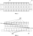
- the positive PV terminals 200a and the negative PV terminals 200b are alternately distributed, as shown in FIG. 4 .
- the positive PV terminals 200a are distributed at one end of the mounting frame 100
- the negative PV terminals 200b are distributed at the other end of the mounting frame 100, as shown in FIG. 5 .
- the positive PV terminals 200a and the negative PV terminals 200b are distributed in other ways, which is not limited in this embodiment.
- adjacent positive PV terminals 200a and negative PV terminals 200b may be in contact with each other, or a gap is arranged between adjacent positive PV terminals 200a and negative PV terminals 200b. It can be understood that the positive PV terminals 200a and the negative PV terminals 200b are distributed in the same direction. For the convenience of connection, the positive PV terminals 200a and the negative PV terminals 200b may be distributed in a same row.
- the PV input port 210 of the PV terminal 200 may include a positive PV input port 210a and a negative PV input port 210b, as shown in FIG. 6 .
- the positive PV input port 210a and the negative PV input port 210b may be sequentially distributed along a height direction of the PV terminal 200, as shown in FIG. 6 .
- the positive PV input port 210a and the negative PV input port 210b may be sequentially distributed along a width direction of the PV terminal 200.
- the positive PV input port 210a and the negative PV input port 210b are located at the same side of the PV terminal 200.
- the PV terminal 200 may be integrated with a sensor, and the PV terminal 200 is provided with a sensor signal output port configured for outputting signals collected by the sensor.
- the PV terminal 200 may be provided with a power input port which is configured for inputting a power supply for supplying power to the sensor. It can be understood that the power input port is connected with the sensor. For the convenience of wiring, the power input port and the PV input port 210 are located at the same side of the PV terminal 200.
- the PV terminal 200 may be integrated with a power supply circuit which is configured for introducing power from the PV input cable 500 connected to the PV terminal 200 and supplying the power to the sensor.
- the PV terminal 200 may be integrated with a terminal-dedicated printed circuit board.
- the terminal-dedicated printed circuit board carries the sensor.
- the terminal-dedicated printed circuit board carries the sensor and the power supply circuit.
- the senor as described above may be a temperature sensor and/or a current sensor and/or a voltage sensor, which is not limited in this embodiment.
- an electrical device is further provided according to this embodiment, as shown in FIG. 7 to FIG. 11 , which includes the PV terminal assembly as described in the above embodiments.
- the above electrical device includes the PV terminal assembly as described above, the above electrical device also has corresponding technical effects, which will not be described in detail here.
- the above electric device includes a cabinet 300 and electronic components fixed in the cabinet 300.
- the mounting frame 100 is fixed to the cabinet 300 or the electronic components.
- the mounting frame 100 may penetrate through a side plate of the cabinet 300, or the mounting frame 100 may be located inside the cabinet 300, which is selected based on actual needs.
- the above electronic components may be printed circuit boards or current detection boards, which is selected based on actual needs and not limited in this embodiment.
- the cabinet 300 is provided with a via hole 310 which allows the PV input port 210 of the PV terminal 200 to be exposed to outside.
- the PV terminal assembly may be hermetically connected with the via hole 310.
- the electrical device may further include a protective cover 400 which is located outside the cabinet 300 and covers the via hole 310.
- the protective cover 400 is hermetically connected with the cabinet 300 and is provided with a wire leading hole for inserting the PV input cable 500.
- the electrical device may include the protective cover 400 as described above.
- the number of the via hole 310 may be one, that is, the PV input ports 210 of all of the PV terminals 200 can be exposed to outside with only one via hole 310.
- the protective cover 400 is provided with a waterproof ring 600 fixed to the wire leading hole, and the waterproof ring 600 is configured for hermetically connecting the wire leading hole and the PV input cable 500.
- the waterproof ring 600 may be any type of waterproof ring as required.
- the wire leading hole is sealed by the waterproof ring 600, and the waterproof ring 600 is puncturable, so that the PV input cable 500 can puncture and pass through the waterproof ring.
- the waterproof ring 600 seals the wire leading hole, and when the PV input cable 500 needs to be mounted, the PV input cable 500 can penetrate through the waterproof ring 600 and pass through the waterproof ring 600. In this way, when the PV input cable 500 does not need to be mounted, there is no need for additional parts to seal the wire leading hole, which reduces the number of components, simplifies the structure and reduces the cost.
- the waterproof ring 600 may only be used for sealingly connecting the wire leading hole and the PV input cable 500, and other parts may be used to seal the wire leading hole separately, which is not limited to the above embodiment.
Landscapes
- Engineering & Computer Science (AREA)
- Microelectronics & Electronic Packaging (AREA)
- Connections Arranged To Contact A Plurality Of Conductors (AREA)
- Mounting Components In General For Electric Apparatus (AREA)
- Casings For Electric Apparatus (AREA)
- Inverter Devices (AREA)
Abstract
Description
- This application claims priority to
Chinese Patent Application No. 202122507851.3, titled "PV TERMINAL ASSEMBLY AND ELECTRICAL DEVICE", filed with the China National Intellectual Property Administration on October 18, 2021 - The present application relates to the technical field of photovoltaic power generation, and in particular to a PV terminal assembly and an electrical device.
- In the field of photovoltaic power generation, an electrical device such as an inverter and a combiner box mainly includes: a cabinet, PV terminals, a current detection board, a direct current switch, a printed circuit board and the like, where PV cables are connected to the PV terminals, the PV terminals are connected to the current detection board through the cable, the current detection board is connected to one side of the direct current switch through the cable, and the other side of the direct current switch is connected to the printed circuit board through the cable.
- In the above-mentioned electrical device, a side plate of the cabinet is provided with fixing holes for mounting the PV terminals, and the above-mentioned PV terminals are mounted in the fixing holes from outside of the cabinet. The fixing holes correspond to the PV terminals respectively, and the number of channels of the PV terminals is settled and unadjustable, resulting in poor extensibility and compatibility of the PV terminals, and smaller application scope of the whole electrical device.
- In addition, each of the PV terminals is hermetically connected with the cabinet, and generally the PV terminals are hermetically connected with the cabinet through sealing members. In order to ensure a successful mounting of each of the PV terminals, a distance between two adjacent fixing holes is large. Therefore, a space occupied by all of the PV terminals is large, and a volume of the whole electrical device is large.
- In summary, the technical problem to be solved by those skilled in the art is to design a PV terminal in such a way that the number of channels of the PV terminals is adjustable and thus the extensibility and compatibility are improved.
- In view of this, an object of the present application is to provide a PV terminal assembly, so that the number of channels of PV terminals is adjustable, and thus the extensibility and compatibility are improved. Another object of the present application is to provide an electrical device including the PV terminal assembly as described above.
- In order to achieve the above objects, the following technical solutions are provided according to the present application.
- A PV terminal assembly includes a mounting frame and at least one PV terminal, where the mounting frame is provided with at least two mounting positions used for fixing the at least one PV terminal.
- In an embodiment, the mounting frame is in a strip shape, and any two of the mounting positions are sequentially distributed along a length direction of the mounting frame.
- In an embodiment, the PV terminal is detachably fixed to the mounting frame.
- In an embodiment, the mounting frame is a guide rail, and the PV terminal clips on the guide rail;
or, the mounting frame is a structural member with a mounting hole, and the PV terminal is fixed to the mounting hole through a fastener. - In an embodiment, a PV input port of the PV terminal is a positive PV input port or a negative PV input port, and the number of the PV terminals is even, where at least one of the PV terminals is a positive PV terminal, and at least one of the PV terminals is a negative PV terminal;
the positive PV terminals and the negative PV terminals are alternately distributed; or the positive PV terminals are distributed at one end of the mounting frame, and the negative PV terminals are distributed at the other end of the mounting frame. - In an embodiment, the PV input port of the PV terminal includes a positive PV input port and a negative PV input port.
- In an embodiment, the PV terminal is integrated with a sensor, and the PV terminal is provided with a sensor signal output port configured for outputting signals collected by the sensor;
where the PV terminal is provided with a power input port which is configured for inputting a power supply for supplying power to the sensor; or, the PV terminal is integrated with a power supply circuit which is configured for introducing power from a PV input cable connected to the PV terminal and supplying the power to the sensor. - In an embodiment, the PV terminal is integrated with a terminal-dedicated printed circuit board;
- in a case that the PV terminal is provided with the power input port, the terminal-dedicated printed circuit board carries the sensor; and
- in a case that the PV terminal is integrated with the power supply circuit, the terminal-dedicated printed circuit board carries the sensor and the power supply circuit.
- In an embodiment, the sensor includes a temperature sensor and/or a current sensor and/or a voltage sensor.
- In the PV terminal assembly provided according to the present application, the mounting frame is provided with at least two mounting positions used for fixing the PV terminals, so that at least two PV terminals are integrated on the mounting frame. The number of channels of PV terminals of the whole PV terminal assembly can be adjusted by adjusting the number of PV terminals on the mounting frame, thereby improving the extensibility and compatibility, enabling the whole electrical device to be compatible with various input configurations, and improving the development efficiency.
- Besides, at least two PV terminals can be integrated on the mounting frame of the PV terminal assembly provided by the present application. In the actual use process, compared with the conventional technology in which each of the PV terminals is separately fixed on the cabinet, the mounting frame disclosed herein is directly fixed on the cabinet, which can reduce the space occupied by all of the PV terminals, thereby reducing the volume of the whole electrical device. Further, the mounting of the PV terminal is simplified and the mounting efficiency is improved.
- Based on the PV terminal assembly provided above, an electrical device is further provided according to the present application, which includes the PV terminal assembly as described above.
- In an embodiment, the electrical device further includes a cabinet and electronic components fixed in the cabinet, where the mounting frame is fixed to the cabinet or the electronic components.
- In an embodiment, the cabinet is provided with a via hole for exposing the PV input port of the PV terminal to outside, and the PV terminal assembly is hermetically connected with the via hole.
- In an embodiment, the cabinet is provided with a via hole for exposing the PV input port of the PV terminal to outside; and
the electrical device further includes a protective cover which is located outside the cabinet and covers the via hole, and the protective cover is hermetically connected with the cabinet and is provided with a wire leading hole for inserting the PV input cable. - In an embodiment, the protective cover is provided with a waterproof ring fixed to the wire leading hole, and the waterproof ring is configured for hermetically connecting the wire leading hole and the PV input cable.
- In an embodiment, the wire leading hole is sealed by the waterproof ring, and the waterproof ring is puncturable, so that the PV input cable can puncture and pass through the waterproof ring.
- For more clearly illustrating embodiments of the present application or technical solutions in the conventional technology, the drawings referred to for describing the embodiments or the conventional technology will be briefly described hereinafter. Apparently, the drawings in the following description are only some examples of the present application, and for those skilled in the art, other drawings may be obtained based on the provided drawings without any creative efforts.
-
FIG. 1 is a schematic structural view of a PV terminal assembly according to an embodiment of the present application; -
FIG. 2 is a side view of the PV terminal assembly according to an embodiment of the present application; -
FIG. 3 is a top view of the PV terminal assembly according to an embodiment of the present application; -
FIG. 4 is a view showing a distribution of PV terminals of the PV terminal assembly according to an embodiment of the present application; -
FIG. 5 is a view showing another distribution of PV terminals of the PV terminal assembly according to an embodiment of the present application; -
FIG. 6 is a view showing another distribution of PV terminals of the PV terminal assembly according to an embodiment of the present application; -
FIG. 7 is a schematic structural view of an electrical device according to an embodiment of the present application; -
FIG. 8 is a partial enlarged view ofFIG. 7 ; -
FIG. 9 is a side view of an electrical device according to an embodiment of the present application; -
FIG. 10 is a cross-sectional view ofFIG. 9 , taken along line A-A; and -
FIG. 11 is a partial enlarged view ofFIG. 10 . - The technical solutions according to the embodiments of the present application will be described clearly and completely as follows in conjunction with the drawings in the embodiments of the present application. It is apparent that the described embodiments are only some of the embodiments according to the present application, rather than all the embodiments. Based on the embodiments in the present application, any other embodiments obtained by those skilled in the art without any creative efforts fall within the protection scope of the present application.
- As shown in
FIG. 1 to FIG. 6 , a PV terminal assembly provided according to an embodiment of the present application includes amounting frame 100 and at least onePV terminal 200. Themounting frame 100 is provided with at least two mounting positions used for fixing the at least onePV terminal 200. - It should be noted that one mounting position is used for mounting one
PV terminal 200, that is, the mounting position is in one-to-one correspondence with thePV terminal 200. The number of the above-mentionedPV terminals 200 may be selected based on actual needs, that is, it is applicable that all of the mounting positions are fixed with thePV terminals 200, and it is also applicable that only some of the mounting positions are fixed with thePV terminals 200, and the rest mounting positions are vacant of thePV terminals 200. - In the PV terminal assembly provided according to the above embodiment, the
mounting frame 100 is provided with at least two mounting positions used for fixing thePV terminals 200, so that at least twoPV terminals 200 are integrated on themounting frame 100. The number of channels of the whole PV terminal assembly can be adjusted by adjusting the number ofPV terminals 200 on themounting frame 100, thereby improving the extensibility and compatibility, enabling the whole electrical device to be compatible with various input configurations, and improving the development efficiency. - Besides, in the PV terminal assembly provided according to the above embodiment, at least two
PV terminals 200 can be integrated on the mountingframe 100. In the actual use process, compared with the conventional technology in which each of the PV terminals is separately fixed on the cabinet, the mountingframe 100 herein is directly fixed on acabinet 300, which can reduce the space occupied by all of thePV terminals 200, thereby reducing the volume of the whole electrical device. Further, the mounting of thePV terminal 200 is simplified and the mounting efficiency is improved. - In a case that the number of the
PV terminal 200 is at least two, twoadjacent PV terminals 200 are in contact with each other, so as to minimize the space occupied by the PV terminal assembly. - In practices, a gap may be provided between two
adjacent PV terminals 200, and a size of the gap is selected based on actual needs, which is not limited in this embodiment. Also, a spacer may be arranged between twoadjacent PV terminals 200, and the spacer is fixed to the mountingframe 100. ThePV terminal 200 may be in contact with the spacer or there is a gap between thePV terminal 200 and the spacer, which depends on actual needs and is not limited in this embodiment. - The shape of the mounting
frame 100 is selected based on actual needs. Optionally, the mountingframe 100 is in a strip shape, and any two of the mounting positions are sequentially distributed along a length direction of the mountingframe 100. It can be understood that if the number of thePV terminals 200 on the mountingframe 100 is at least two, any two of thePV terminals 200 are sequentially distributed along the length direction of the mountingframe 100. - In particular, the mounting
frame 100 is rectangular. In practices, the mountingframe 100 may also be in other shapes, such as square and the like, which is not limited in this embodiment. - In order to further improve the extensibility and compatibility, the
PV terminal 200 is detachably fixed to the mountingframe 100. In this way, the number of thePV terminals 200 on the mountingframe 100 is adjustable at will, which increases an adjustment range. - In practices, the
PV terminal 200 may be detachably fixed to the mountingframe 100 through a threaded connector, or thePV terminal 200 may be detachably fixed to the mountingframe 100 through a clip-on structure, which is selected based on actual needs. - In particular, in a case that the mounting
frame 100 is a guide rail, thePV terminal 200 may clip on theguide rail 100. In a case that the mountingframe 100 is a structural member with a mounting hole, thePV terminal 200 may be fixed to the mounting hole by a fastener. It can be understood that thePV terminal 200 may be detachably fixed to the mounting hole by a fastener. - In the above-mentioned PV terminal assembly, the specific structure of the
PV terminal 200 is selected based on actual needs. In particular, thePV terminal 200 has aPV input port 210 and aPV output port 220. APV input cable 500 is connected to thePV input port 210. For the convenience of mounting, a connection end of thePV input cable 500 is provided with a PV pin, and the PV pin is connected with thePV input port 210. - Optionally, the
PV input port 210 of thePV terminal 200 is a positivePV input port 210a or a negativePV input port 210b. In this case, the number of thePV terminals 200 is even, where at least one of thePV terminals 200 is apositive PV terminal 200a, and at least one of thePV terminals 200 is anegative PV terminal 200b. - It can be understood that the
PV input port 210 of thepositive PV terminal 200a is the positivePV input port 210a, and thePV input port 210 of thenegative PV terminal 200b is the negativePV input port 210b. - In the above-mentioned
PV terminals 200, thepositive PV terminals 200a and thenegative PV terminals 200b are alternately distributed, as shown inFIG. 4 . Alternatively, thepositive PV terminals 200a are distributed at one end of the mountingframe 100, and thenegative PV terminals 200b are distributed at the other end of the mountingframe 100, as shown inFIG. 5 . Alternatively, thepositive PV terminals 200a and thenegative PV terminals 200b are distributed in other ways, which is not limited in this embodiment. - Among the above-mentioned
PV terminals 200, in a case that thepositive PV terminals 200a are distributed at one end of the mountingframe 100 and thenegative PV terminals 200b are distributed at the other end of the mountingframe 100, adjacentpositive PV terminals 200a andnegative PV terminals 200b may be in contact with each other, or a gap is arranged between adjacentpositive PV terminals 200a andnegative PV terminals 200b. It can be understood that thepositive PV terminals 200a and thenegative PV terminals 200b are distributed in the same direction. For the convenience of connection, thepositive PV terminals 200a and thenegative PV terminals 200b may be distributed in a same row. - In practices, the
PV input port 210 of thePV terminal 200 may include a positivePV input port 210a and a negativePV input port 210b, as shown inFIG. 6 . Optionally, in each of thePV terminals 200, the positivePV input port 210a and the negativePV input port 210b may be sequentially distributed along a height direction of thePV terminal 200, as shown inFIG. 6 . Alternatively, in each of thePV terminals 200, the positivePV input port 210a and the negativePV input port 210b may be sequentially distributed along a width direction of thePV terminal 200. - It can be understood that the positive
PV input port 210a and the negativePV input port 210b are located at the same side of thePV terminal 200. - In the electrical device, it is generally required to collect required signals, such as temperature signals, current signals and voltage signals. In order to simplify the structure, the
PV terminal 200 may be integrated with a sensor, and thePV terminal 200 is provided with a sensor signal output port configured for outputting signals collected by the sensor. - In order to ensure the power supply to the sensor, the
PV terminal 200 may be provided with a power input port which is configured for inputting a power supply for supplying power to the sensor. It can be understood that the power input port is connected with the sensor. For the convenience of wiring, the power input port and thePV input port 210 are located at the same side of thePV terminal 200. - In practices, the
PV terminal 200 may be integrated with a power supply circuit which is configured for introducing power from thePV input cable 500 connected to thePV terminal 200 and supplying the power to the sensor. - For the PV terminal assembly described above, in order to facilitate the assembly of the sensor and the power supply circuit, the
PV terminal 200 may be integrated with a terminal-dedicated printed circuit board. In a case that thePV terminal 200 is provided with the power input port, the terminal-dedicated printed circuit board carries the sensor. In a case that thePV terminal 200 is integrated with the power supply circuit, the terminal-dedicated printed circuit board carries the sensor and the power supply circuit. - A type of the above sensor is selected based on actual needs. For example, the sensor as described above may be a temperature sensor and/or a current sensor and/or a voltage sensor, which is not limited in this embodiment.
- Based on the PV terminal assembly provided in the above embodiments, an electrical device is further provided according to this embodiment, as shown in
FIG. 7 to FIG. 11 , which includes the PV terminal assembly as described in the above embodiments. - Since the PV terminal assembly according to above embodiments has the above technical effects, and the above electrical device includes the PV terminal assembly as described above, the above electrical device also has corresponding technical effects, which will not be described in detail here.
- The above electric device includes a
cabinet 300 and electronic components fixed in thecabinet 300. The mountingframe 100 is fixed to thecabinet 300 or the electronic components. In particular, the mountingframe 100 may penetrate through a side plate of thecabinet 300, or the mountingframe 100 may be located inside thecabinet 300, which is selected based on actual needs. - The above electronic components may be printed circuit boards or current detection boards, which is selected based on actual needs and not limited in this embodiment.
- In order to ensure wiring, the
cabinet 300 is provided with a viahole 310 which allows thePV input port 210 of thePV terminal 200 to be exposed to outside. In order to ensure the protection requirements, the PV terminal assembly may be hermetically connected with the viahole 310. Alternatively, the electrical device may further include aprotective cover 400 which is located outside thecabinet 300 and covers the viahole 310. Theprotective cover 400 is hermetically connected with thecabinet 300 and is provided with a wire leading hole for inserting thePV input cable 500. - In practices, in order to facilitate sealing, the electrical device may include the
protective cover 400 as described above. In order to simplify the structure, the number of the viahole 310 may be one, that is, thePV input ports 210 of all of thePV terminals 200 can be exposed to outside with only one viahole 310. - In order to facilitate the sealing of the
PV input cable 500 and the wire leading hole, theprotective cover 400 is provided with a waterproof ring 600 fixed to the wire leading hole, and the waterproof ring 600 is configured for hermetically connecting the wire leading hole and thePV input cable 500. - The waterproof ring 600 may be any type of waterproof ring as required. In order to facilitate the sealing and wiring, the wire leading hole is sealed by the waterproof ring 600, and the waterproof ring 600 is puncturable, so that the
PV input cable 500 can puncture and pass through the waterproof ring. In particular, when thePV input cable 500 is not mounted, the waterproof ring 600 seals the wire leading hole, and when thePV input cable 500 needs to be mounted, thePV input cable 500 can penetrate through the waterproof ring 600 and pass through the waterproof ring 600. In this way, when thePV input cable 500 does not need to be mounted, there is no need for additional parts to seal the wire leading hole, which reduces the number of components, simplifies the structure and reduces the cost. - In practices, the waterproof ring 600 may only be used for sealingly connecting the wire leading hole and the
PV input cable 500, and other parts may be used to seal the wire leading hole separately, which is not limited to the above embodiment. - Based on the above description of the disclosed embodiments, the present application can be implemented or used by those skilled in the art. Various modifications to these embodiments are apparent to those skilled in the art, and the general principle defined herein may be implemented in other embodiments without departing from the spirit or scope of the present application. Hence, the present application is not limited to the embodiments disclosed herein, but shall conform to the widest scope in accordance with the principle and novel features disclosed herein.
Claims (15)
- A PV terminal assembly, comprising a mounting frame (100) and at least one PV terminal (200), wherein the mounting frame (100) is provided with at least two mounting positions used for fixing the at least one PV terminal (200).
- The PV terminal assembly according to claim 1, wherein the mounting frame (100) is in a strip shape, and any two of the mounting positions are sequentially distributed along a length direction of the mounting frame (100).
- The PV terminal assembly according to claim 1, wherein the at least one PV terminal (200) is detachably fixed to the mounting frame (100).
- The PV terminal assembly according to claim 1, whereinthe mounting frame (100) is a guide rail, and the at least one PV terminal (200) clips on the guide rail (100); or,the mounting frame (100) is a structural member with a mounting hole, and the at least one PV terminal (200) is fixed to the mounting hole through a fastener.
- The PV terminal assembly according to claim 1, whereina PV input port (210) of each PV terminal (200) is a positive PV input port (210a) or a negative PV input port (210b), and the number of the at least one PV terminal (200) is even, wherein at least one of the PV terminals (200) is a positive PV terminal (200a), and at least one of the PV terminals (200) is a negative PV terminal (200b);the at least one positive PV terminal (200a) and the at least one negative PV terminal (200b) are alternately distributed; or the at least one positive PV terminal (200a) is distributed at one end of the mounting frame (100), and the at least one negative PV terminal (200b) is distributed at the other end of the mounting frame (100).
- The PV terminal assembly according to claim 1, wherein a PV input port (210) of each PV terminal (200) comprises a positive PV input port (210a) and a negative PV input port (210b).
- The PV terminal assembly according to any one of claims 1 to 6, whereinthe PV terminal (200) is integrated with a sensor, and the PV terminal (200) is provided with a sensor signal output port configured for outputting signals collected by the sensor;wherein the PV terminal (200) is provided with a power input port which is configured for inputting a power supply for supplying power to the sensor; or, the PV terminal (200) is integrated with a power supply circuit which is configured for introducing power from a PV input cable (500) connected to the PV terminal (200) and supplying the power to the sensor.
- The PV terminal assembly according to claim 7, wherein the PV terminal (200) is integrated with a terminal-dedicated printed circuit board;in a case that the PV terminal (200) is provided with the power input port, the terminal-dedicated printed circuit board carries the sensor; andin a case that the PV terminal (200) is integrated with the power supply circuit, the terminal-dedicated printed circuit board carries the sensor and the power supply circuit.
- The PV terminal assembly according to claim 7, wherein the sensor comprises: a temperature sensor and/or a current sensor and/or a voltage sensor.
- An electrical device, comprising the PV terminal assembly according to any one of claims 1 to 9.
- The electric device according to claim 10, further comprising: a cabinet (300) and electronic components fixed in the cabinet (300), wherein the mounting frame (100) is fixed to the cabinet (300) or the electronic components.
- The electrical device according to claim 11, wherein the cabinet (300) is provided with a via hole (310) for exposing the PV input port (210) of the PV terminal (200) to outside, and the PV terminal assembly is hermetically connected with the via hole (310).
- The electrical device according to claim 11, whereinthe cabinet (300) is provided with a via hole (310) for exposing the PV input port (210) of the PV terminal (200) to outside; andthe electrical device further comprises a protective cover (400) which is located outside the cabinet (300) and covers the via hole (310), and the protective cover (400) is hermetically connected with the cabinet (300) and is provided with a wire leading hole for inserting the PV input cable (500).
- The electrical device according to claim 13, wherein the protective cover (400) is provided with a waterproof ring (600) fixed to the wire leading hole, and the waterproof ring (600) is configured for hermetically connecting the wire leading hole and the PV input cable (500).
- The electrical device according to claim 14, wherein the wire leading hole is sealed by the waterproof ring (600), and the waterproof ring (600) is puncturable, so that the PV input cable (500) can puncture and pass through the waterproof ring (600).
Applications Claiming Priority (2)
| Application Number | Priority Date | Filing Date | Title |
|---|---|---|---|
| CN202122507851.3U CN216214188U (en) | 2021-10-18 | 2021-10-18 | PV terminal assembly and electrical device |
| PCT/CN2022/094952 WO2023065664A1 (en) | 2021-10-18 | 2022-05-25 | Pv terminal assembly and electrical device |
Publications (2)
| Publication Number | Publication Date |
|---|---|
| EP4366093A1 true EP4366093A1 (en) | 2024-05-08 |
| EP4366093A4 EP4366093A4 (en) | 2025-06-18 |
Family
ID=80883772
Family Applications (1)
| Application Number | Title | Priority Date | Filing Date |
|---|---|---|---|
| EP22882289.6A Pending EP4366093A4 (en) | 2021-10-18 | 2022-05-25 | PV TERMINAL AND ELECTRICAL DEVICE ASSEMBLY |
Country Status (7)
| Country | Link |
|---|---|
| US (1) | US20240356249A1 (en) |
| EP (1) | EP4366093A4 (en) |
| JP (1) | JP7716566B2 (en) |
| KR (1) | KR20240038764A (en) |
| CN (1) | CN216214188U (en) |
| AU (1) | AU2022368601B2 (en) |
| WO (1) | WO2023065664A1 (en) |
Families Citing this family (1)
| Publication number | Priority date | Publication date | Assignee | Title |
|---|---|---|---|---|
| CN216214188U (en) * | 2021-10-18 | 2022-04-05 | 阳光电源股份有限公司 | PV terminal assembly and electrical device |
Family Cites Families (16)
| Publication number | Priority date | Publication date | Assignee | Title |
|---|---|---|---|---|
| DE202006003596U1 (en) * | 2006-03-07 | 2006-07-13 | Butzer, Werner | Fotovoltaikanlage |
| US8732940B2 (en) * | 2009-03-12 | 2014-05-27 | Clean Energy Solutions, Inc. | System and method for mounting photovoltaic panels |
| US8187016B2 (en) * | 2010-03-05 | 2012-05-29 | Xunlight Corporation | Terminal assembly including a junction box for a photovoltaic module and method of forming |
| JP2013140705A (en) * | 2011-12-29 | 2013-07-18 | Jonan Denki Seiki Kk | Terminal block with measuring function |
| CN203351877U (en) * | 2013-07-10 | 2013-12-18 | 迈柯唯医疗设备(苏州)有限公司 | Integrated type quick plug weak current connecting module |
| JP6295603B2 (en) * | 2013-10-29 | 2018-03-20 | 株式会社ノーリツ | Inverter |
| US8938932B1 (en) * | 2013-12-13 | 2015-01-27 | Quality Product Llc | Rail-less roof mounting system |
| CN204118935U (en) * | 2014-07-18 | 2015-01-21 | 利莱森玛电机科技(福州)有限公司 | Terminal assemblies, terminal box and motor |
| US9496697B1 (en) * | 2015-10-16 | 2016-11-15 | Imagineering Plus Plus Llc | Roof top junction box |
| JP2017079562A (en) * | 2015-10-21 | 2017-04-27 | 三菱電機株式会社 | Connection box for photovoltaic power generation |
| LU92994B1 (en) * | 2016-03-11 | 2017-10-23 | Phoenix Contact Gmbh & Co Kg Intellectual Property Licenses & Standards | DIN rail assembly with a bus system and a circuit board having electronic device |
| CN206452353U (en) * | 2017-02-23 | 2017-08-29 | 温馨 | A kind of adjustable solar photovoltaic bracket used for vegetable greenhouse |
| US11489485B2 (en) * | 2019-01-16 | 2022-11-01 | CubeX Solar, LLC | Foldable solar power system |
| CN212571572U (en) * | 2020-12-22 | 2021-02-19 | 菲尼克斯(南京)新能源汽车技术有限公司 | Integrated electric PCB system and charging plug |
| CN113366928A (en) * | 2021-03-17 | 2021-09-07 | 华为技术有限公司 | Photovoltaic power conversion device |
| CN216214188U (en) * | 2021-10-18 | 2022-04-05 | 阳光电源股份有限公司 | PV terminal assembly and electrical device |
-
2021
- 2021-10-18 CN CN202122507851.3U patent/CN216214188U/en active Active
-
2022
- 2022-05-25 WO PCT/CN2022/094952 patent/WO2023065664A1/en not_active Ceased
- 2022-05-25 KR KR1020247005939A patent/KR20240038764A/en active Pending
- 2022-05-25 AU AU2022368601A patent/AU2022368601B2/en active Active
- 2022-05-25 JP JP2024503665A patent/JP7716566B2/en active Active
- 2022-05-25 EP EP22882289.6A patent/EP4366093A4/en active Pending
- 2022-05-25 US US18/683,507 patent/US20240356249A1/en active Pending
Also Published As
| Publication number | Publication date |
|---|---|
| US20240356249A1 (en) | 2024-10-24 |
| JP7716566B2 (en) | 2025-07-31 |
| EP4366093A4 (en) | 2025-06-18 |
| WO2023065664A1 (en) | 2023-04-27 |
| AU2022368601A1 (en) | 2024-02-08 |
| CN216214188U (en) | 2022-04-05 |
| KR20240038764A (en) | 2024-03-25 |
| JP2024525906A (en) | 2024-07-12 |
| AU2022368601B2 (en) | 2025-09-04 |
Similar Documents
| Publication | Publication Date | Title |
|---|---|---|
| US4985845A (en) | Modular electrical control distribution system | |
| CN103856164B (en) | Junction box, solar cell, and method of installing bus bars in junction box | |
| US20140293553A1 (en) | Modular solar box | |
| WO2010019754A2 (en) | Photovoltaic panel having snap engagement features | |
| GB2262000B (en) | Junction box | |
| US9466961B2 (en) | Generator connection box for photovoltaic installations | |
| EP2482403A1 (en) | Junction box for solar cell component and solar cell component | |
| WO2011040784A2 (en) | Solar photovoltaic device | |
| CA2154614A1 (en) | Mounting device for rj connection elements for communication and data transfer (patch panel) | |
| US20240356249A1 (en) | Pv terminal assembly and electrical device | |
| US20110220187A1 (en) | Junction Module for A Building Integrated Photovoltaic System | |
| WO2024245452A1 (en) | Ccs protective cap, ccs assembly and battery pack | |
| CN112564592A (en) | Point-supported photovoltaic module | |
| WO2021096297A1 (en) | Function-specific modular inverter system | |
| CN220022748U (en) | Photovoltaic junction box | |
| CN214848258U (en) | Measurement switch | |
| CN214281281U (en) | Point-supported photovoltaic module | |
| CN212970266U (en) | Double-shaft motor drive control printed circuit board assembly and double-shaft motor drive controller | |
| CN222763206U (en) | A control pole connection system and power distribution equipment | |
| CN218070935U (en) | Multifunctional integrated junction box | |
| CN219917697U (en) | Single current-carrying connector and grid-connected system | |
| CN219918156U (en) | Cabinet type change-over switch device | |
| CN216698765U (en) | Mounting structure of wiring terminal subassembly | |
| CN219247230U (en) | Drawer and power distribution cabinet | |
| CN204517181U (en) | Complete LV intelligent switching system switch cubicle |
Legal Events
| Date | Code | Title | Description |
|---|---|---|---|
| STAA | Information on the status of an ep patent application or granted ep patent |
Free format text: STATUS: THE INTERNATIONAL PUBLICATION HAS BEEN MADE |
|
| PUAI | Public reference made under article 153(3) epc to a published international application that has entered the european phase |
Free format text: ORIGINAL CODE: 0009012 |
|
| STAA | Information on the status of an ep patent application or granted ep patent |
Free format text: STATUS: REQUEST FOR EXAMINATION WAS MADE |
|
| 17P | Request for examination filed |
Effective date: 20240130 |
|
| AK | Designated contracting states |
Kind code of ref document: A1 Designated state(s): AL AT BE BG CH CY CZ DE DK EE ES FI FR GB GR HR HU IE IS IT LI LT LU LV MC MK MT NL NO PL PT RO RS SE SI SK SM TR |
|
| DAV | Request for validation of the european patent (deleted) | ||
| DAX | Request for extension of the european patent (deleted) | ||
| A4 | Supplementary search report drawn up and despatched |
Effective date: 20250519 |
|
| RIC1 | Information provided on ipc code assigned before grant |
Ipc: H01R 12/51 20110101ALI20250513BHEP Ipc: H05K 5/02 20060101ALI20250513BHEP Ipc: H02S 40/30 20140101ALI20250513BHEP Ipc: H02G 3/08 20060101ALI20250513BHEP Ipc: H01R 9/26 20060101AFI20250513BHEP |