EP4366031A1 - System and method for early-stage detection of thermal runaway in lithium-ion batteries - Google Patents
System and method for early-stage detection of thermal runaway in lithium-ion batteries Download PDFInfo
- Publication number
- EP4366031A1 EP4366031A1 EP23201497.7A EP23201497A EP4366031A1 EP 4366031 A1 EP4366031 A1 EP 4366031A1 EP 23201497 A EP23201497 A EP 23201497A EP 4366031 A1 EP4366031 A1 EP 4366031A1
- Authority
- EP
- European Patent Office
- Prior art keywords
- voc
- capsule
- capsule shell
- battery
- boiling point
- Prior art date
- Legal status (The legal status is an assumption and is not a legal conclusion. Google has not performed a legal analysis and makes no representation as to the accuracy of the status listed.)
- Pending
Links
- 238000001514 detection method Methods 0.000 title claims description 18
- 229910001416 lithium ion Inorganic materials 0.000 title description 5
- HBBGRARXTFLTSG-UHFFFAOYSA-N Lithium ion Chemical compound [Li+] HBBGRARXTFLTSG-UHFFFAOYSA-N 0.000 title description 4
- 238000000034 method Methods 0.000 title 1
- 239000012855 volatile organic compound Substances 0.000 claims abstract description 127
- 239000002775 capsule Substances 0.000 claims abstract description 116
- 238000009835 boiling Methods 0.000 claims abstract description 35
- 238000009834 vaporization Methods 0.000 claims abstract description 31
- 230000008016 vaporization Effects 0.000 claims abstract description 31
- 238000012546 transfer Methods 0.000 claims abstract description 15
- 239000007788 liquid Substances 0.000 claims abstract description 12
- 239000004020 conductor Substances 0.000 claims abstract description 10
- 230000006378 damage Effects 0.000 claims description 11
- 239000000853 adhesive Substances 0.000 claims description 4
- 230000001070 adhesive effect Effects 0.000 claims description 4
- 238000010943 off-gassing Methods 0.000 description 8
- 238000010438 heat treatment Methods 0.000 description 7
- WEVYAHXRMPXWCK-UHFFFAOYSA-N Acetonitrile Chemical compound CC#N WEVYAHXRMPXWCK-UHFFFAOYSA-N 0.000 description 6
- XEKOWRVHYACXOJ-UHFFFAOYSA-N Ethyl acetate Chemical compound CCOC(C)=O XEKOWRVHYACXOJ-UHFFFAOYSA-N 0.000 description 6
- 150000001875 compounds Chemical class 0.000 description 6
- 238000006243 chemical reaction Methods 0.000 description 5
- XTHFKEDIFFGKHM-UHFFFAOYSA-N Dimethoxyethane Chemical compound COCCOC XTHFKEDIFFGKHM-UHFFFAOYSA-N 0.000 description 4
- WYURNTSHIVDZCO-UHFFFAOYSA-N Tetrahydrofuran Chemical compound C1CCOC1 WYURNTSHIVDZCO-UHFFFAOYSA-N 0.000 description 4
- XLYOFNOQVPJJNP-UHFFFAOYSA-N water Substances O XLYOFNOQVPJJNP-UHFFFAOYSA-N 0.000 description 3
- WNXJIVFYUVYPPR-UHFFFAOYSA-N 1,3-dioxolane Chemical compound C1COCO1 WNXJIVFYUVYPPR-UHFFFAOYSA-N 0.000 description 2
- HTWIZMNMTWYQRN-UHFFFAOYSA-N 2-methyl-1,3-dioxolane Chemical compound CC1OCCO1 HTWIZMNMTWYQRN-UHFFFAOYSA-N 0.000 description 2
- JWUJQDFVADABEY-UHFFFAOYSA-N 2-methyltetrahydrofuran Chemical compound CC1CCCO1 JWUJQDFVADABEY-UHFFFAOYSA-N 0.000 description 2
- SBUOHGKIOVRDKY-UHFFFAOYSA-N 4-methyl-1,3-dioxolane Chemical compound CC1COCO1 SBUOHGKIOVRDKY-UHFFFAOYSA-N 0.000 description 2
- OIFBSDVPJOWBCH-UHFFFAOYSA-N Diethyl carbonate Chemical compound CCOC(=O)OCC OIFBSDVPJOWBCH-UHFFFAOYSA-N 0.000 description 2
- XBDQKXXYIPTUBI-UHFFFAOYSA-M Propionate Chemical compound CCC([O-])=O XBDQKXXYIPTUBI-UHFFFAOYSA-M 0.000 description 2
- KXKVLQRXCPHEJC-UHFFFAOYSA-N acetic acid trimethyl ester Natural products COC(C)=O KXKVLQRXCPHEJC-UHFFFAOYSA-N 0.000 description 2
- 230000007547 defect Effects 0.000 description 2
- 238000004519 manufacturing process Methods 0.000 description 2
- 239000000463 material Substances 0.000 description 2
- 238000012544 monitoring process Methods 0.000 description 2
- YLQBMQCUIZJEEH-UHFFFAOYSA-N tetrahydrofuran Natural products C=1C=COC=1 YLQBMQCUIZJEEH-UHFFFAOYSA-N 0.000 description 2
- 230000001960 triggered effect Effects 0.000 description 2
- 238000013022 venting Methods 0.000 description 2
- OKTJSMMVPCPJKN-UHFFFAOYSA-N Carbon Chemical compound [C] OKTJSMMVPCPJKN-UHFFFAOYSA-N 0.000 description 1
- RYGMFSIKBFXOCR-UHFFFAOYSA-N Copper Chemical compound [Cu] RYGMFSIKBFXOCR-UHFFFAOYSA-N 0.000 description 1
- BQCADISMDOOEFD-UHFFFAOYSA-N Silver Chemical compound [Ag] BQCADISMDOOEFD-UHFFFAOYSA-N 0.000 description 1
- 229910000831 Steel Inorganic materials 0.000 description 1
- HCHKCACWOHOZIP-UHFFFAOYSA-N Zinc Chemical compound [Zn] HCHKCACWOHOZIP-UHFFFAOYSA-N 0.000 description 1
- 230000002159 abnormal effect Effects 0.000 description 1
- 238000009825 accumulation Methods 0.000 description 1
- 229910052782 aluminium Inorganic materials 0.000 description 1
- XAGFODPZIPBFFR-UHFFFAOYSA-N aluminium Chemical compound [Al] XAGFODPZIPBFFR-UHFFFAOYSA-N 0.000 description 1
- 230000005779 cell damage Effects 0.000 description 1
- 208000037887 cell injury Diseases 0.000 description 1
- 229910052729 chemical element Inorganic materials 0.000 description 1
- 238000007796 conventional method Methods 0.000 description 1
- 229910052802 copper Inorganic materials 0.000 description 1
- 239000010949 copper Substances 0.000 description 1
- 238000007599 discharging Methods 0.000 description 1
- 239000003792 electrolyte Substances 0.000 description 1
- 238000004880 explosion Methods 0.000 description 1
- 230000006870 function Effects 0.000 description 1
- PCHJSUWPFVWCPO-UHFFFAOYSA-N gold Chemical compound [Au] PCHJSUWPFVWCPO-UHFFFAOYSA-N 0.000 description 1
- 229910052737 gold Inorganic materials 0.000 description 1
- 239000010931 gold Substances 0.000 description 1
- 229910002804 graphite Inorganic materials 0.000 description 1
- 239000010439 graphite Substances 0.000 description 1
- 229910052500 inorganic mineral Inorganic materials 0.000 description 1
- 230000002427 irreversible effect Effects 0.000 description 1
- 229910052751 metal Inorganic materials 0.000 description 1
- 239000002184 metal Substances 0.000 description 1
- 229910001092 metal group alloy Inorganic materials 0.000 description 1
- 239000011707 mineral Substances 0.000 description 1
- 238000012986 modification Methods 0.000 description 1
- 230000004048 modification Effects 0.000 description 1
- 238000013021 overheating Methods 0.000 description 1
- 239000004033 plastic Substances 0.000 description 1
- 238000009877 rendering Methods 0.000 description 1
- 229910052709 silver Inorganic materials 0.000 description 1
- 239000004332 silver Substances 0.000 description 1
- 239000000779 smoke Substances 0.000 description 1
- 239000002904 solvent Substances 0.000 description 1
- 230000007480 spreading Effects 0.000 description 1
- 239000010959 steel Substances 0.000 description 1
- 239000000126 substance Substances 0.000 description 1
- 208000024891 symptom Diseases 0.000 description 1
- 229920002994 synthetic fiber Polymers 0.000 description 1
- 229920001059 synthetic polymer Polymers 0.000 description 1
- 230000007704 transition Effects 0.000 description 1
- 229910052725 zinc Inorganic materials 0.000 description 1
- 239000011701 zinc Substances 0.000 description 1
Images



Classifications
-
- H—ELECTRICITY
- H01—ELECTRIC ELEMENTS
- H01M—PROCESSES OR MEANS, e.g. BATTERIES, FOR THE DIRECT CONVERSION OF CHEMICAL ENERGY INTO ELECTRICAL ENERGY
- H01M10/00—Secondary cells; Manufacture thereof
- H01M10/60—Heating or cooling; Temperature control
- H01M10/65—Means for temperature control structurally associated with the cells
- H01M10/654—Means for temperature control structurally associated with the cells located inside the innermost case of the cells, e.g. mandrels, electrodes or electrolytes
-
- H—ELECTRICITY
- H01—ELECTRIC ELEMENTS
- H01M—PROCESSES OR MEANS, e.g. BATTERIES, FOR THE DIRECT CONVERSION OF CHEMICAL ENERGY INTO ELECTRICAL ENERGY
- H01M10/00—Secondary cells; Manufacture thereof
- H01M10/42—Methods or arrangements for servicing or maintenance of secondary cells or secondary half-cells
- H01M10/48—Accumulators combined with arrangements for measuring, testing or indicating the condition of cells, e.g. the level or density of the electrolyte
- H01M10/486—Accumulators combined with arrangements for measuring, testing or indicating the condition of cells, e.g. the level or density of the electrolyte for measuring temperature
-
- H—ELECTRICITY
- H01—ELECTRIC ELEMENTS
- H01M—PROCESSES OR MEANS, e.g. BATTERIES, FOR THE DIRECT CONVERSION OF CHEMICAL ENERGY INTO ELECTRICAL ENERGY
- H01M10/00—Secondary cells; Manufacture thereof
- H01M10/05—Accumulators with non-aqueous electrolyte
- H01M10/052—Li-accumulators
-
- H—ELECTRICITY
- H01—ELECTRIC ELEMENTS
- H01M—PROCESSES OR MEANS, e.g. BATTERIES, FOR THE DIRECT CONVERSION OF CHEMICAL ENERGY INTO ELECTRICAL ENERGY
- H01M10/00—Secondary cells; Manufacture thereof
- H01M10/42—Methods or arrangements for servicing or maintenance of secondary cells or secondary half-cells
- H01M10/4235—Safety or regulating additives or arrangements in electrodes, separators or electrolyte
-
- H—ELECTRICITY
- H01—ELECTRIC ELEMENTS
- H01M—PROCESSES OR MEANS, e.g. BATTERIES, FOR THE DIRECT CONVERSION OF CHEMICAL ENERGY INTO ELECTRICAL ENERGY
- H01M10/00—Secondary cells; Manufacture thereof
- H01M10/42—Methods or arrangements for servicing or maintenance of secondary cells or secondary half-cells
- H01M10/48—Accumulators combined with arrangements for measuring, testing or indicating the condition of cells, e.g. the level or density of the electrolyte
- H01M10/482—Accumulators combined with arrangements for measuring, testing or indicating the condition of cells, e.g. the level or density of the electrolyte for several batteries or cells simultaneously or sequentially
-
- H—ELECTRICITY
- H01—ELECTRIC ELEMENTS
- H01M—PROCESSES OR MEANS, e.g. BATTERIES, FOR THE DIRECT CONVERSION OF CHEMICAL ENERGY INTO ELECTRICAL ENERGY
- H01M10/00—Secondary cells; Manufacture thereof
- H01M10/60—Heating or cooling; Temperature control
- H01M10/61—Types of temperature control
- H01M10/613—Cooling or keeping cold
-
- H—ELECTRICITY
- H01—ELECTRIC ELEMENTS
- H01M—PROCESSES OR MEANS, e.g. BATTERIES, FOR THE DIRECT CONVERSION OF CHEMICAL ENERGY INTO ELECTRICAL ENERGY
- H01M50/00—Constructional details or processes of manufacture of the non-active parts of electrochemical cells other than fuel cells, e.g. hybrid cells
- H01M50/30—Arrangements for facilitating escape of gases
- H01M50/383—Flame arresting or ignition-preventing means
-
- H—ELECTRICITY
- H01—ELECTRIC ELEMENTS
- H01M—PROCESSES OR MEANS, e.g. BATTERIES, FOR THE DIRECT CONVERSION OF CHEMICAL ENERGY INTO ELECTRICAL ENERGY
- H01M10/00—Secondary cells; Manufacture thereof
- H01M10/42—Methods or arrangements for servicing or maintenance of secondary cells or secondary half-cells
- H01M10/425—Structural combination with electronic components, e.g. electronic circuits integrated to the outside of the casing
- H01M2010/4278—Systems for data transfer from batteries, e.g. transfer of battery parameters to a controller, data transferred between battery controller and main controller
-
- H—ELECTRICITY
- H01—ELECTRIC ELEMENTS
- H01M—PROCESSES OR MEANS, e.g. BATTERIES, FOR THE DIRECT CONVERSION OF CHEMICAL ENERGY INTO ELECTRICAL ENERGY
- H01M2200/00—Safety devices for primary or secondary batteries
- H01M2200/10—Temperature sensitive devices
-
- H—ELECTRICITY
- H01—ELECTRIC ELEMENTS
- H01M—PROCESSES OR MEANS, e.g. BATTERIES, FOR THE DIRECT CONVERSION OF CHEMICAL ENERGY INTO ELECTRICAL ENERGY
- H01M2300/00—Electrolytes
- H01M2300/0017—Non-aqueous electrolytes
- H01M2300/0025—Organic electrolyte
-
- Y—GENERAL TAGGING OF NEW TECHNOLOGICAL DEVELOPMENTS; GENERAL TAGGING OF CROSS-SECTIONAL TECHNOLOGIES SPANNING OVER SEVERAL SECTIONS OF THE IPC; TECHNICAL SUBJECTS COVERED BY FORMER USPC CROSS-REFERENCE ART COLLECTIONS [XRACs] AND DIGESTS
- Y02—TECHNOLOGIES OR APPLICATIONS FOR MITIGATION OR ADAPTATION AGAINST CLIMATE CHANGE
- Y02E—REDUCTION OF GREENHOUSE GAS [GHG] EMISSIONS, RELATED TO ENERGY GENERATION, TRANSMISSION OR DISTRIBUTION
- Y02E60/00—Enabling technologies; Technologies with a potential or indirect contribution to GHG emissions mitigation
- Y02E60/10—Energy storage using batteries
Definitions
- Example embodiments of the present disclosure relate generally to detecting abnormal battery conditions, and in particular, providing an early indicator of thermal runaway.
- Thermal runaway is one of the primary risks related to using lithium-ion batteries in electrical vehicles. Thermal runaway may be triggered by mishandling or management of a lithium-ion battery unit via, for example, electrical abuse, mechanical abuse, thermal abuse, water ingress, or manufacturing defect of the battery. Electrical abuse may comprise improper charging/discharging, or a short circuit of a battery unit. Mechanical abuse may comprise impact or physical damage to a battery unit. Thermal abuse may comprise over heating of a battery unit. Water ingress may comprise a presence of water in a battery unit. Manufacturing defect may comprise an improperly manufactured battery unit that is unsuitable for the purpose for which it was designed. As such, thermal runaway may occur as a result of such mishandling or management.
- Thermal runaway may comprise a condition where a battery cell experiences an increase in temperature such that when the temperature reaches a particular threshold, the battery cell may cause a chain reaction with neighboring battery cells that result in smoke, fire, or explosion.
- a gas detection sensor may be used to detect potential thermal runaway by detecting gas vented from a battery unit or cell.
- Applicant has identified that when a battery cell has reached a point where it vents gas, the battery cell may have already suffered irreversible damage, rendering gas detection ineffective in detecting early-stage thermal runaway.
- Various embodiments described herein relate to components, apparatuses, and systems for detecting thermal runaway in batteries.
- a thermally reactive capsule coupled to a battery cell comprises a capsule shell comprising a thermally conductive material that transfers heat from a surface of a battery cell to the capsule shell, a volatile organic compound ("VOC") stored within a cavity of the capsule shell, wherein the VOC is in a liquid state and at a temperature below boiling point of the VOC, and the boiling point of the VOC is below a threshold temperature.
- the thermally reactive capsule further comprising one or more pressure relief devices configured on a surface of the capsule shell, wherein pressure generated by vaporization of the VOC causes opening of the one or more pressure relief devices.
- the vaporization of the VOC comprises a conversion of the VOC from liquid state to gas state. In some embodiments, the vaporization is caused by a transfer of heat from the surface of the battery cell to the capsule shell, wherein the heat causes the VOC to reach or exceed the boiling point of the VOC. In some embodiments, the capsule shell is adhered to the surface of the battery cell with thermally conductive adhesive. In some embodiments, the VOC comprises a compound associated with battery off-gassing.
- the VOC comprises a compound selected from the group consisting of diethyl carbonate, ethyl acetate, methyl acetate, 1,2-dimethoxyethane, tetrahydrofuran, 2-methyl-tetrahydrofuran, 1,3-dioxolane, 4-methyl 1,3-dioxolane, 2-methyl 1,3-dioxolane, and acetonitrile.
- the boiling point of the VOC is within a range of approximately 50°C to 100°C.
- opening of the one or more pressure relief devices comprises releasing of VOC gas associated with the vaporization of the VOC.
- the threshold temperature comprises a temperature below a temperature associated with a risk of damage to the battery cell.
- a system for detecting thermal runaway in batteries comprises one or more thermally reactive capsules coupled to one or more battery cells.
- Each of the one or more thermally reactive capsules comprising a capsule shell comprising a thermally conductive material that transfers heat from a surface of a selected one of the one or more battery cells to the capsule shell, a volatile organic compound ("VOC") stored within a cavity of the capsule shell, wherein the VOC is in a liquid state and at a temperature below boiling point of the VOC, and the boiling point of the VOC is below a threshold temperature, and one or more pressure relief devices configured on a surface of the capsule shell, wherein pressure generated by vaporization of the VOC causes opening of the one or more pressure relief devices.
- the system further comprises a gas sensor configured to detect the vaporization of the VOC.
- the vaporization of the VOC comprises a conversion of the VOC from liquid state to gas state. In some embodiments, the vaporization is caused by a transfer of heat from the surface of the battery cell to the capsule shell, wherein the heat causes the VOC to reach or exceed the boiling point of the VOC. In some embodiments, the VOC comprises a compound associated with battery off-gassing. In some embodiments, the boiling point of the VOC is within a range of approximately 50°C to 100°C. In some embodiments, opening of the one or more pressure relief devices comprises releasing of VOC gas associated with the vaporization of the VOC. In some embodiments, the threshold temperature comprises a temperature below a temperature associated with a risk of damage to the battery cell.
- a system comprises one or more thermally reactive capsules coupled to one or more battery cells of a battery pack, each of the one or more thermally reactive capsules comprising a capsule shell comprising a thermally conductive material that transfers heat from a surface of a selected one of the one or more battery cells to the capsule shell, a volatile organic compound ("VOC") stored within a cavity of the capsule shell, wherein the VOC is in a liquid state and at a temperature below boiling point of the VOC, and the boiling point of the VOC is below a threshold temperature, and one or more pressure relief devices configured on a surface of the capsule shell, wherein pressure generated by vaporization of the VOC causes opening of the one or more pressure relief devices.
- the system further comprises a gas sensor coupled to a battery management system, wherein the gas sensor is configured to detect VOC gas from the vaporization of the VOC, and transmit a data signal to the battery management system, the data signal representative of the detection of the VOC gas.
- the battery management system is configured to determine thermal runaway based on the data signal. In some embodiments, the battery management system is configured to communicate with a charge controller to manage charging parameters of the battery pack based on the data signal. In some embodiments, the vaporization is caused by a transfer of heat from the surface of the battery cell to the capsule shell, wherein the heat causes the VOC to reach or exceed the boiling point of the VOC.
- the term "comprising” means including but not limited to and should be interpreted in the manner it is typically used in the patent context. Use of broader terms such as comprises, includes, and having should be understood to provide support for narrower terms such as consisting of, consisting essentially of, and comprised substantially of.
- ком ⁇ онент or feature may,” “can,” “could,” “should,” “would,” “preferably,” “possibly,” “typically,” “optionally,” “for example,” “often,” or “might” (or other such language) be included or have a characteristic, that a specific component or feature is not required to be included or to have the characteristic. Such a component or feature may be optionally included in some embodiments, or it may be excluded.
- thermal runaway detection for batteries there are many technical challenges and difficulties associated with thermal runaway detection for batteries.
- conventional methods for detecting thermal runaway such as the use of gas sensors are not designed to detect early stages of thermal runaway prior to battery off-gassing. That is, gas sensors can only detect thermal runaway once cell damage has occurred.
- gas sensors can only detect thermal runaway once cell damage has occurred.
- a thermally reactive capsule containing a volatile organic compound may be coupled to one or more cells in a battery unit to provide or enhance thermal runaway detection.
- FIG. 1A presents an exemplary thermally reactive capsule according to an embodiment of the present disclosure.
- Thermally reactive capsule 100 comprises a capsule shell 102 and VOC 104 stored within a cavity formed within capsule shell 102.
- the capsule shell 102 may comprise a thermally conductive material, such as metal, metal alloys, chemical elements, minerals, synthetic materials, polymers, or any other material possessing the ability to readily receive or transfer heat. Examples of thermally conductive material suitable for capsule shell 102 may include aluminum, copper, silver, gold, graphite, zinc, steel, or plastic.
- the thermally conductive material of capsule shell 102 may allow for conductive heat transfer from a material or object that is in direct contact with capsule shell 102.
- Capsule 100 may comprise any shape and size suitable for placement on a battery cell within a battery unit.
- VOC 104 may be stored within capsule shell 102 in a liquid state, that is, at a temperature below the VOC 104 boiling point.
- the VOC 104 may comprise a chemical that is in a liquid state when its temperature is below its boiling point and becomes a gas when its temperature reaches or exceed its boiling point.
- VOC 104 may comprise a compound associated with battery off-gassing, such as solvents for lithium-ion battery electrolytes.
- the boiling point of VOC 104 may be, for example, within a range of approximately 50°C to 100°C.
- VOC 104 may comprise a compound that is selected with a boiling point corresponding to a range of temperatures below a threshold temperature.
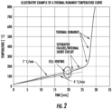
- the threshold temperature may comprise a temperature below temperatures that would cause damage to a battery cell, such as battery cell venting temperature, as depicted on a thermal runaway temperature curve in FIG. 2 .
- VOC 104 may include, but not limited to, diethyl carbonate, ethyl acetate, methyl acetate, 1,2-dimethoxyethane, tetrahydrofuran, 2-methyl-tetrahydrofuran, 1,3-dioxolane, 4-methyl 1,3-dioxolane, 2-methyl 1,3-dioxolane, and acetonitrile.
- the capsule shell 102 further comprises one or more scoring(s) 102A on a surface of capsule shell 102.
- the one or more scoring(s) 102A may comprise a pressure relief device capable of releasing internal pressure contained within capsule shell 102 exceeding a given amount.
- the one or more scoring(s) 102A may remain intact provided that the temperature of VOC 104 is under its boiling point.
- the one or more scoring(s) 102A may be opened at the one or more scoring(s) 102A upon internal pressure of capsule shell 102 exceeding a certain amount pressure generated by vaporization of VOC 104 caused by temperature of VOC 104 reaching its boiling point.
- one or more scoring(s) 102A may be omitted from capsule shell 102.
- capsule shell 102 may be constructed such that internal pressure created by vaporization of VOC 104 would be sufficient to open any portion of a surface of capsule shell 102 without one or more scoring(s) 102A.
- capsule shell 102 may comprise one or more thinned wall portions in place of one or more scoring(s) 102A.
- capsule shell 102 may comprise an apparatus comprising a mechanical pressure switch that can be triggered by pressure to turn an electrical circuit on or off.
- One or more of capsule 100 may be adhered directly to a surface of one or more battery cells of a battery unit for detection of thermal runaway.
- Thermal runaway may occur when the temperature inside a battery cell reaches a point that causes a chemical reaction to occur inside the battery cell, which in turn, may produce even more heat driving the temperature of the battery cell even higher such that the temperature may eventually rise at an exponential rate, further leading to a chain reaction of spreading heat to other battery cells.
- capsule shell 102 may be adhered (e.g., via thermally conductive adhesive) to a surface of a battery cell.
- FIG. 1B presents an exemplary thermally reactive capsule exposed to heating according to an embodiment of the present disclosure.
- Capsule 100 may be adhered to a surface of a source of heating 108.
- Heating 108 may comprise an emission of conductive heat, e.g., from a surface of a battery cell. The heating 108 may be transferred to capsule shell 102.
- capsule 100 may react to heating 108 by releasing VOC gas 110 as a result of heating 108 causing vaporization of VOC 104.
- heating 108 may be transferred to capsule shell 102 and may cause the temperature of VOC 104 to reach its boiling point.
- the VOC 104 may transition from a liquid state to a gas state (VOC gas 110), e.g., via vaporization, which may cause an increase in pressure within capsule shell 102.
- the increase in pressure may reach or exceed a limit of the one or more scoring(s) 102A, causing the one or more scoring(s) 102A to open.
- One or more aperture(s) 102B may be formed from opening of one or more scoring(s) 102A, and thus releasing VOC gas 110 from capsule 100.
- VOC gas 110 released through the one or more aperture(s) 102B may be detected by a gas sensor, thus, serving as an early-stage warning indicator of thermal runaway.
- Capsule 100 may be depleted of VOC 104 once the one or more scoring(s) 102A are opened and become one or more aperture(s) 102B. In the case that VOC 104 is depleted from capsule 100, capsule 100 may no longer be of further use and may be replaced with another one of capsule 100 with unopened one or more scoring(s).102A.
- FIG. 3 depicts an exemplary battery pack.
- Battery pack 300 comprises a plurality of battery cells 302.
- the battery cells 302 may be configured in series, parallel, or a combination thereof to deliver a desired voltage, capacity, or power density.
- the battery pack 300 may comprise an electric vehicle battery pack.
- battery cells 302 may comprise lithium-ion cells.
- capsule 100 may be adhered to one or more of battery cells 302 or to the battery pack 300.
- a VOC may be directly embedded within the housing of the battery cells 302 or battery pack 300.
- FIG. 4 presents an exemplary system for thermal runaway detection according to an embodiment of the present disclosure.
- a system 400 comprises battery cell 302, capsule 100, and gas sensor 402.
- capsule 100 may be adhered (e.g., using thermally conductive adhesive) or configured directly in contact with a surface of battery cell 302 such that thermal energy may be conducted from the surface of the battery cell 302 to capsule 100.
- capsule 100 may comprise a capsule shell 102 and VOC 104 stored within a cavity formed by capsule shell 102.
- Capsule 100 may be used as an indicator of excessive heat generated by battery cell 302 that is beyond a predetermined temperature that causes the capsule 100 to release VOC gas 110.
- the predetermined temperature may be below a temperature associated with a risk of damage to the battery cell 302, such as a temperature when battery cell venting starts to occur. Accordingly, battery cell 302 may generate heat to sufficiently heat VOC 104 within capsule 100 to cause vaporization of VOC 104 at the predetermined temperature. Vaporization of VOC 104 may occur once boiling point of VOC 104 is reached. The vaporization of VOC 104 may cause an accumulation of internal pressure in the capsule 100.
- the increased internal pressure may cause rapturing of capsule 100, e.g., via one or more scoring(s) 102A, releasing VOC gas 110.
- the VOC gas 110 may be detected by gas sensor 402.
- Gas sensor 402 may comprise a sensor capable of detecting battery off-gassing, such as VOC gas 110.
- system 400 may provide detection of early-stage symptoms of thermal runaway by detecting a release of VOC gas 110 from capsule 100 rather than off-gassing from the battery cell 302 itself.
- the presently disclosed system is thus capable of providing an earlier indication of thermal runaway such that permanent damage to battery cell 302 can be avoided.
- the capsule 100 may be applied to battery cells to provide early warnings of battery cell issues such that immediate servicing of a battery unit system may be undertaken.
- capsule 100 may be a replaceable item that can be replaced during servicing of a battery cell or unit.
- FIG. 5 presents an exemplary battery system incorporating thermal runaway detection according to an embodiment of the present disclosure.
- Battery system 500 comprises battery pack 502, capsule(s) 504, gas sensor 506, battery management system 508, and charge controller 512.
- Battery pack 502 may comprise a plurality of battery cells configured in series, parallel, or a combination thereof to deliver a desired voltage, capacity, or power density.
- Each of one or more of the plurality of battery cells may be configured with capsule(s) 504 such that heat from the one or more battery cells of the battery pack 502 may be conducted to the capsule(s) 504.
- Capsule(s) 504 may comprise a capsule shell stored with VOC therewith, as disclosed according to various embodiments of the present disclosure. If sufficient heat is conducted to capsule(s) 504 from the one or more battery cells of the battery pack 502, e.g., a temperature that causes VOC within capsule(s) 504 to reach boiling point, VOC gas 510 (resulting from vaporization of the VOC) may be released from capsule(s) 504.
- the gas sensor 506 may comprise a sensor capable of detecting battery off-gassing.
- VOC gas 510 may comprise a compound vapor associated with battery off-gassing.
- system 500 may provide for early detection of thermal runaway by monitoring for a condition where battery cells within battery pack 502 reach a certain temperature that is enough to open capsule(s) 504 rather than the battery cells themselves, such that permanent damage to the battery cells can be prevented.
- gas sensor 506 may detect the VOC gas 510 and transmit a data signal including an event, e.g., detection of VOC gas 510, to battery management system 508.
- Battery management system 508 may perform appropriate functions to prevent further increase in temperature and damage to battery pack 502 based on the data signal from gas sensor 506.
- Battery management system 508 may comprise a computing device or processor configured to protect and ensure safe operation of battery pack 502. For example, battery management system 508 may monitor battery cells, provide protection to the battery cells, optimize performance of the battery cells, and report operational status of the battery cells to a device control unit. According to one embodiment, battery management system 508 may monitor or receive data signals from gas sensor 506. As such, battery management system 508 may be configured to determine early-stage thermal runaway based on data signals representative of a detection of VOC gas 510 by gas sensor 506. The battery management system 508 may monitor the status of battery pack 502 (e.g., including the detection of VOC gas 510) and communicate with charge controller 512 to manage charging parameters of battery pack 502 based on the monitoring.
- battery management system 508 may monitor battery cells, provide protection to the battery cells, optimize performance of the battery cells, and report operational status of the battery cells to a device control unit.
- battery management system 508 may monitor or receive data signals from gas sensor 506.
- battery management system 508 may be configured to determine early-stage
- Charge controller 512 may comprise a computing device or processor configured to provide charging of battery pack 502 at given currents and voltages.
- a processor may comprise programmable logic devices, microprocessors, multi-core processors, coprocessing entities, application-specific instruction-set processors (ASIPs), microcontrollers, and/or controllers.
- ASIPs application-specific instruction-set processors
- microcontrollers and/or controllers.
Landscapes
- Chemical & Material Sciences (AREA)
- Chemical Kinetics & Catalysis (AREA)
- Electrochemistry (AREA)
- General Chemical & Material Sciences (AREA)
- Engineering & Computer Science (AREA)
- Manufacturing & Machinery (AREA)
- Secondary Cells (AREA)
- Battery Mounting, Suspending (AREA)
Abstract
A thermally reactive capsule coupled to a battery cell, the thermally reactive capsule comprising a capsule shell comprising a thermally conductive material that transfers heat from a surface of the battery cell to the capsule shell, a volatile organic compound ("VOC") stored within a cavity of the capsule shell, wherein the VOC is in a liquid state and at a temperature below boiling point of the VOC, and the boiling point of the VOC is below a threshold temperature. The thermally reactive capsule further comprising one or more pressure relief devices configured on a surface of the capsule shell, wherein pressure generated by vaporization of the VOC causes opening of the one or more pressure relief devices.
Description
- Example embodiments of the present disclosure relate generally to detecting abnormal battery conditions, and in particular, providing an early indicator of thermal runaway.
- Thermal runaway is one of the primary risks related to using lithium-ion batteries in electrical vehicles. Thermal runaway may be triggered by mishandling or management of a lithium-ion battery unit via, for example, electrical abuse, mechanical abuse, thermal abuse, water ingress, or manufacturing defect of the battery. Electrical abuse may comprise improper charging/discharging, or a short circuit of a battery unit. Mechanical abuse may comprise impact or physical damage to a battery unit. Thermal abuse may comprise over heating of a battery unit. Water ingress may comprise a presence of water in a battery unit. Manufacturing defect may comprise an improperly manufactured battery unit that is unsuitable for the purpose for which it was designed. As such, thermal runaway may occur as a result of such mishandling or management.
- Thermal runaway may comprise a condition where a battery cell experiences an increase in temperature such that when the temperature reaches a particular threshold, the battery cell may cause a chain reaction with neighboring battery cells that result in smoke, fire, or explosion. A gas detection sensor may be used to detect potential thermal runaway by detecting gas vented from a battery unit or cell. However, Applicant has identified that when a battery cell has reached a point where it vents gas, the battery cell may have already suffered irreversible damage, rendering gas detection ineffective in detecting early-stage thermal runaway.
- Various embodiments described herein relate to components, apparatuses, and systems for detecting thermal runaway in batteries.
- In accordance with various embodiments of the present disclosure, a thermally reactive capsule coupled to a battery cell is provided. In some embodiments, the thermally reactive capsule comprises a capsule shell comprising a thermally conductive material that transfers heat from a surface of a battery cell to the capsule shell, a volatile organic compound ("VOC") stored within a cavity of the capsule shell, wherein the VOC is in a liquid state and at a temperature below boiling point of the VOC, and the boiling point of the VOC is below a threshold temperature. The thermally reactive capsule further comprising one or more pressure relief devices configured on a surface of the capsule shell, wherein pressure generated by vaporization of the VOC causes opening of the one or more pressure relief devices.
- In some embodiments, the vaporization of the VOC comprises a conversion of the VOC from liquid state to gas state. In some embodiments, the vaporization is caused by a transfer of heat from the surface of the battery cell to the capsule shell, wherein the heat causes the VOC to reach or exceed the boiling point of the VOC. In some embodiments, the capsule shell is adhered to the surface of the battery cell with thermally conductive adhesive. In some embodiments, the VOC comprises a compound associated with battery off-gassing. In some embodiments, the VOC comprises a compound selected from the group consisting of diethyl carbonate, ethyl acetate, methyl acetate, 1,2-dimethoxyethane, tetrahydrofuran, 2-methyl-tetrahydrofuran, 1,3-dioxolane, 4-methyl 1,3-dioxolane, 2-methyl 1,3-dioxolane, and acetonitrile. In some embodiments, the boiling point of the VOC is within a range of approximately 50°C to 100°C. In some embodiments, opening of the one or more pressure relief devices comprises releasing of VOC gas associated with the vaporization of the VOC. In some embodiments, the threshold temperature comprises a temperature below a temperature associated with a risk of damage to the battery cell.
- According to another embodiment, a system for detecting thermal runaway in batteries is provided. The system comprises one or more thermally reactive capsules coupled to one or more battery cells. Each of the one or more thermally reactive capsules comprising a capsule shell comprising a thermally conductive material that transfers heat from a surface of a selected one of the one or more battery cells to the capsule shell, a volatile organic compound ("VOC") stored within a cavity of the capsule shell, wherein the VOC is in a liquid state and at a temperature below boiling point of the VOC, and the boiling point of the VOC is below a threshold temperature, and one or more pressure relief devices configured on a surface of the capsule shell, wherein pressure generated by vaporization of the VOC causes opening of the one or more pressure relief devices. The system further comprises a gas sensor configured to detect the vaporization of the VOC.
- In some embodiments, the vaporization of the VOC comprises a conversion of the VOC from liquid state to gas state. In some embodiments, the vaporization is caused by a transfer of heat from the surface of the battery cell to the capsule shell, wherein the heat causes the VOC to reach or exceed the boiling point of the VOC. In some embodiments, the VOC comprises a compound associated with battery off-gassing. In some embodiments, the boiling point of the VOC is within a range of approximately 50°C to 100°C. In some embodiments, opening of the one or more pressure relief devices comprises releasing of VOC gas associated with the vaporization of the VOC. In some embodiments, the threshold temperature comprises a temperature below a temperature associated with a risk of damage to the battery cell.
- According to another embodiment, a system is provided that comprises one or more thermally reactive capsules coupled to one or more battery cells of a battery pack, each of the one or more thermally reactive capsules comprising a capsule shell comprising a thermally conductive material that transfers heat from a surface of a selected one of the one or more battery cells to the capsule shell, a volatile organic compound ("VOC") stored within a cavity of the capsule shell, wherein the VOC is in a liquid state and at a temperature below boiling point of the VOC, and the boiling point of the VOC is below a threshold temperature, and one or more pressure relief devices configured on a surface of the capsule shell, wherein pressure generated by vaporization of the VOC causes opening of the one or more pressure relief devices. The system further comprises a gas sensor coupled to a battery management system, wherein the gas sensor is configured to detect VOC gas from the vaporization of the VOC, and transmit a data signal to the battery management system, the data signal representative of the detection of the VOC gas.
- In some embodiments, the battery management system is configured to determine thermal runaway based on the data signal. In some embodiments, the battery management system is configured to communicate with a charge controller to manage charging parameters of the battery pack based on the data signal. In some embodiments, the vaporization is caused by a transfer of heat from the surface of the battery cell to the capsule shell, wherein the heat causes the VOC to reach or exceed the boiling point of the VOC.
- The foregoing illustrative summary, as well as other exemplary objectives and/or advantages of the disclosure, and the manner in which the same are accomplished, are further explained in the following detailed description and its accompanying drawings.
- The description of the illustrative embodiments may be read in conjunction with the accompanying figures. It will be appreciated that, for simplicity and clarity of illustration, elements illustrated in the figures have not necessarily been drawn to scale, unless described otherwise. For example, the dimensions of some of the elements may be exaggerated relative to other elements, unless described otherwise. Embodiments incorporating teachings of the present disclosure are shown and described with respect to the figures presented herein, in which:
-
FIG. 1A and FIG. 1B illustrate an exemplary thermally reactive capsule in accordance with some example embodiments described herein. -
FIG. 2 illustrates an exemplary thermal runaway temperature curve. -
FIG. 3 illustrates an exemplary battery pack for implementing various embodiments of the present disclosure. -
FIG. 4 illustrates an exemplary system for thermal runaway detection in accordance with various embodiments of the present disclosure. -
FIG. 5 illustrates an exemplary battery system incorporating thermal runaway detection in accordance with various embodiments of the present disclosure. - Some embodiments of the present disclosure will now be described more fully hereinafter with reference to the accompanying drawings, in which some, but not all embodiments of the disclosure are shown. Indeed, these disclosures may be embodied in many different forms and should not be construed as limited to the embodiments set forth herein; rather, these embodiments are provided so that this disclosure will satisfy applicable legal requirements. Like numbers refer to like elements throughout.
- As used herein, terms such as "front," "rear," "top," etc. are used for explanatory purposes in the examples provided below to describe the relative position of certain components or portions of components. Furthermore, as would be evident to one of ordinary skill in the art in light of the present disclosure, the terms "substantially" and "approximately" indicate that the referenced element or associated description is accurate to within applicable engineering tolerances.
- As used herein, the term "comprising" means including but not limited to and should be interpreted in the manner it is typically used in the patent context. Use of broader terms such as comprises, includes, and having should be understood to provide support for narrower terms such as consisting of, consisting essentially of, and comprised substantially of.
- The phrases "in one embodiment," "according to one embodiment," and the like generally mean that the particular feature, structure, or characteristic following the phrase may be included in at least one embodiment of the present disclosure, and may be included in more than one embodiment of the present disclosure (importantly, such phrases do not necessarily refer to the same embodiment).
- The word "example" or "exemplary" is used herein to mean "serving as an example, instance, or illustration." Any implementation described herein as "exemplary" is not necessarily to be construed as preferred or advantageous over other implementations.
- If the specification states a component or feature "may," "can," "could," "should," "would," "preferably," "possibly," "typically," "optionally," "for example," "often," or "might" (or other such language) be included or have a characteristic, that a specific component or feature is not required to be included or to have the characteristic. Such a component or feature may be optionally included in some embodiments, or it may be excluded.
- As described above, there are many technical challenges and difficulties associated with thermal runaway detection for batteries. In particular, conventional methods for detecting thermal runaway, such as the use of gas sensors are not designed to detect early stages of thermal runaway prior to battery off-gassing. That is, gas sensors can only detect thermal runaway once cell damage has occurred. Thus, there is a need to overcome such challenges and difficulties in early-stage thermal runaway detection for batteries.
- According to various embodiments of the present disclosure, a thermally reactive capsule containing a volatile organic compound ("VOC") may be coupled to one or more cells in a battery unit to provide or enhance thermal runaway detection.
-
FIG. 1A presents an exemplary thermally reactive capsule according to an embodiment of the present disclosure. Thermallyreactive capsule 100 comprises acapsule shell 102 andVOC 104 stored within a cavity formed withincapsule shell 102. Thecapsule shell 102 may comprise a thermally conductive material, such as metal, metal alloys, chemical elements, minerals, synthetic materials, polymers, or any other material possessing the ability to readily receive or transfer heat. Examples of thermally conductive material suitable forcapsule shell 102 may include aluminum, copper, silver, gold, graphite, zinc, steel, or plastic. The thermally conductive material ofcapsule shell 102 may allow for conductive heat transfer from a material or object that is in direct contact withcapsule shell 102.Capsule 100 may comprise any shape and size suitable for placement on a battery cell within a battery unit. -
VOC 104 may be stored withincapsule shell 102 in a liquid state, that is, at a temperature below theVOC 104 boiling point. TheVOC 104 may comprise a chemical that is in a liquid state when its temperature is below its boiling point and becomes a gas when its temperature reaches or exceed its boiling point.VOC 104 may comprise a compound associated with battery off-gassing, such as solvents for lithium-ion battery electrolytes. The boiling point ofVOC 104 may be, for example, within a range of approximately 50°C to 100°C. According to various embodiments of the present disclosure,VOC 104 may comprise a compound that is selected with a boiling point corresponding to a range of temperatures below a threshold temperature. The threshold temperature may comprise a temperature below temperatures that would cause damage to a battery cell, such as battery cell venting temperature, as depicted on a thermal runaway temperature curve inFIG. 2 . Examples ofVOC 104 may include, but not limited to, diethyl carbonate, ethyl acetate, methyl acetate, 1,2-dimethoxyethane, tetrahydrofuran, 2-methyl-tetrahydrofuran, 1,3-dioxolane, 4-methyl 1,3-dioxolane, 2-methyl 1,3-dioxolane, and acetonitrile. - The
capsule shell 102 further comprises one or more scoring(s) 102A on a surface ofcapsule shell 102. The one or more scoring(s) 102A may comprise a pressure relief device capable of releasing internal pressure contained withincapsule shell 102 exceeding a given amount. The one or more scoring(s) 102A may remain intact provided that the temperature ofVOC 104 is under its boiling point. The one or more scoring(s) 102A may be opened at the one or more scoring(s) 102A upon internal pressure ofcapsule shell 102 exceeding a certain amount pressure generated by vaporization ofVOC 104 caused by temperature ofVOC 104 reaching its boiling point. - According to one or more alternative embodiments, one or more scoring(s) 102A may be omitted from
capsule shell 102. For example,capsule shell 102 may be constructed such that internal pressure created by vaporization ofVOC 104 would be sufficient to open any portion of a surface ofcapsule shell 102 without one or more scoring(s) 102A. In another embodiment,capsule shell 102 may comprise one or more thinned wall portions in place of one or more scoring(s) 102A. In yet another embodiment,capsule shell 102 may comprise an apparatus comprising a mechanical pressure switch that can be triggered by pressure to turn an electrical circuit on or off. - One or more of
capsule 100 may be adhered directly to a surface of one or more battery cells of a battery unit for detection of thermal runaway. Thermal runaway may occur when the temperature inside a battery cell reaches a point that causes a chemical reaction to occur inside the battery cell, which in turn, may produce even more heat driving the temperature of the battery cell even higher such that the temperature may eventually rise at an exponential rate, further leading to a chain reaction of spreading heat to other battery cells. As such, to detect increases in battery cell temperature at early stages of thermal runaway,capsule shell 102 may be adhered (e.g., via thermally conductive adhesive) to a surface of a battery cell. -
FIG. 1B presents an exemplary thermally reactive capsule exposed to heating according to an embodiment of the present disclosure.Capsule 100 may be adhered to a surface of a source ofheating 108.Heating 108 may comprise an emission of conductive heat, e.g., from a surface of a battery cell. Theheating 108 may be transferred tocapsule shell 102. - In one embodiment,
capsule 100 may react toheating 108 by releasingVOC gas 110 as a result ofheating 108 causing vaporization ofVOC 104. In particular,heating 108 may be transferred tocapsule shell 102 and may cause the temperature ofVOC 104 to reach its boiling point. Upon the temperature ofVOC 104 reaching its boiling point, theVOC 104 may transition from a liquid state to a gas state (VOC gas 110), e.g., via vaporization, which may cause an increase in pressure withincapsule shell 102. The increase in pressure may reach or exceed a limit of the one or more scoring(s) 102A, causing the one or more scoring(s) 102A to open. One or more aperture(s) 102B may be formed from opening of one or more scoring(s) 102A, and thus releasingVOC gas 110 fromcapsule 100.VOC gas 110 released through the one or more aperture(s) 102B may be detected by a gas sensor, thus, serving as an early-stage warning indicator of thermal runaway.Capsule 100 may be depleted ofVOC 104 once the one or more scoring(s) 102A are opened and become one or more aperture(s) 102B. In the case thatVOC 104 is depleted fromcapsule 100,capsule 100 may no longer be of further use and may be replaced with another one ofcapsule 100 with unopened one or more scoring(s).102A. -
FIG. 3 depicts an exemplary battery pack.Battery pack 300 comprises a plurality ofbattery cells 302. Thebattery cells 302 may be configured in series, parallel, or a combination thereof to deliver a desired voltage, capacity, or power density. For example, thebattery pack 300 may comprise an electric vehicle battery pack. In at least one embodiment,battery cells 302 may comprise lithium-ion cells. According to various embodiments of the present disclosure,capsule 100 may be adhered to one or more ofbattery cells 302 or to thebattery pack 300. According to an alternative embodiment, a VOC may be directly embedded within the housing of thebattery cells 302 orbattery pack 300. -
FIG. 4 presents an exemplary system for thermal runaway detection according to an embodiment of the present disclosure. Asystem 400 comprisesbattery cell 302,capsule 100, andgas sensor 402. According to various embodiments of the present disclosure,capsule 100 may be adhered (e.g., using thermally conductive adhesive) or configured directly in contact with a surface ofbattery cell 302 such that thermal energy may be conducted from the surface of thebattery cell 302 tocapsule 100. As discussed above,capsule 100 may comprise acapsule shell 102 andVOC 104 stored within a cavity formed bycapsule shell 102. -
Capsule 100 may be used as an indicator of excessive heat generated bybattery cell 302 that is beyond a predetermined temperature that causes thecapsule 100 to releaseVOC gas 110. For example, the predetermined temperature may be below a temperature associated with a risk of damage to thebattery cell 302, such as a temperature when battery cell venting starts to occur. Accordingly,battery cell 302 may generate heat to sufficiently heatVOC 104 withincapsule 100 to cause vaporization ofVOC 104 at the predetermined temperature. Vaporization ofVOC 104 may occur once boiling point ofVOC 104 is reached. The vaporization ofVOC 104 may cause an accumulation of internal pressure in thecapsule 100. As such, the increased internal pressure may cause rapturing ofcapsule 100, e.g., via one or more scoring(s) 102A, releasingVOC gas 110. TheVOC gas 110 may be detected bygas sensor 402.Gas sensor 402 may comprise a sensor capable of detecting battery off-gassing, such asVOC gas 110. - Accordingly,
system 400 may provide detection of early-stage symptoms of thermal runaway by detecting a release ofVOC gas 110 fromcapsule 100 rather than off-gassing from thebattery cell 302 itself. The presently disclosed system is thus capable of providing an earlier indication of thermal runaway such that permanent damage tobattery cell 302 can be avoided. Thecapsule 100 may be applied to battery cells to provide early warnings of battery cell issues such that immediate servicing of a battery unit system may be undertaken. According to various embodiments of the present disclosure,capsule 100 may be a replaceable item that can be replaced during servicing of a battery cell or unit. -
FIG. 5 presents an exemplary battery system incorporating thermal runaway detection according to an embodiment of the present disclosure.Battery system 500 comprisesbattery pack 502, capsule(s) 504,gas sensor 506,battery management system 508, andcharge controller 512.Battery pack 502 may comprise a plurality of battery cells configured in series, parallel, or a combination thereof to deliver a desired voltage, capacity, or power density. Each of one or more of the plurality of battery cells may be configured with capsule(s) 504 such that heat from the one or more battery cells of thebattery pack 502 may be conducted to the capsule(s) 504. - Capsule(s) 504 may comprise a capsule shell stored with VOC therewith, as disclosed according to various embodiments of the present disclosure. If sufficient heat is conducted to capsule(s) 504 from the one or more battery cells of the
battery pack 502, e.g., a temperature that causes VOC within capsule(s) 504 to reach boiling point, VOC gas 510 (resulting from vaporization of the VOC) may be released from capsule(s) 504. Thegas sensor 506 may comprise a sensor capable of detecting battery off-gassing.VOC gas 510 may comprise a compound vapor associated with battery off-gassing. - Accordingly,
system 500 may provide for early detection of thermal runaway by monitoring for a condition where battery cells withinbattery pack 502 reach a certain temperature that is enough to open capsule(s) 504 rather than the battery cells themselves, such that permanent damage to the battery cells can be prevented. When capsule(s) 504releases VOC gas 510,gas sensor 506 may detect theVOC gas 510 and transmit a data signal including an event, e.g., detection ofVOC gas 510, tobattery management system 508.Battery management system 508 may perform appropriate functions to prevent further increase in temperature and damage tobattery pack 502 based on the data signal fromgas sensor 506. -
Battery management system 508 may comprise a computing device or processor configured to protect and ensure safe operation ofbattery pack 502. For example,battery management system 508 may monitor battery cells, provide protection to the battery cells, optimize performance of the battery cells, and report operational status of the battery cells to a device control unit. According to one embodiment,battery management system 508 may monitor or receive data signals fromgas sensor 506. As such,battery management system 508 may be configured to determine early-stage thermal runaway based on data signals representative of a detection ofVOC gas 510 bygas sensor 506. Thebattery management system 508 may monitor the status of battery pack 502 (e.g., including the detection of VOC gas 510) and communicate withcharge controller 512 to manage charging parameters ofbattery pack 502 based on the monitoring.Charge controller 512 may comprise a computing device or processor configured to provide charging ofbattery pack 502 at given currents and voltages. As disclosed herewith, a processor may comprise programmable logic devices, microprocessors, multi-core processors, coprocessing entities, application-specific instruction-set processors (ASIPs), microcontrollers, and/or controllers. - It is to be understood that the disclosure is not to be limited to the specific embodiments disclosed, and that modifications and other embodiments are intended to be included within the scope of the appended claims. Although specific terms are employed herein, they are used in a generic and descriptive sense only and not for purposes of limitation, unless described otherwise.
Claims (15)
- A thermally reactive capsule coupled to a battery cell, the thermally reactive capsule comprising:a capsule shell comprising a thermally conductive material that transfers heat from a surface of the battery cell to the capsule shell;a volatile organic compound ("VOC") stored within a cavity of the capsule shell, the VOC in a liquid state and at a temperature below boiling point of the VOC, wherein the boiling point of the VOC is below a threshold temperature; andone or more pressure relief devices configured on a surface of the capsule shell, wherein pressure generated by vaporization of the VOC causes opening of the one or more pressure relief devices.
- The thermally reactive capsule of claim 1, wherein the vaporization is caused by a transfer of heat from the surface of the battery cell to the capsule shell, the heat causing the VOC to reach or exceed the boiling point of the VOC.
- The thermally reactive capsule of claim 1, wherein the capsule shell is adhered to the surface of the battery cell with thermally conductive adhesive.
- The thermally reactive capsule of claim 1, wherein the boiling point of the VOC is within a range of approximately 50°C to 100°C.
- The thermally reactive capsule of claim 1, wherein opening of the one or more pressure relief devices comprises releasing of VOC gas associated with the vaporization of the VOC.
- The thermally reactive capsule of claim 1, wherein the threshold temperature comprises a temperature below a temperature associated with a risk of damage to the battery cell.
- A system for detecting thermal runaway in batteries, the system comprising:one or more thermally reactive capsules coupled to one or more battery cells, each of the one or more thermally reactive capsules comprising:a capsule shell comprising a thermally conductive material that transfers heat from a surface of a selected one of the one or more battery cells to the capsule shell,a volatile organic compound ("VOC") stored within a cavity of the capsule shell, the VOC in a liquid state and at a temperature below boiling point of the VOC, wherein the boiling point of the VOC is below a threshold temperature, andone or more pressure relief devices configured on a surface of the capsule shell, wherein pressure generated by vaporization of the VOC causes opening of the one or more pressure relief devices; anda gas sensor configured to detect the vaporization of the VOC.
- The system of claim 7, wherein the vaporization is caused by a transfer of heat from the surface of the battery cell to the capsule shell, the heat causing the VOC to reach or exceed the boiling point of the VOC.
- The system of claim 7, wherein the boiling point of the VOC is within a range of approximately 50°C to 100°C.
- The system of claim 7, wherein opening of the one or more pressure relief devices comprises releasing of VOC gas associated with the vaporization of the VOC.
- The system of claim 7, wherein the threshold temperature comprises a temperature below a temperature associated with a risk of damage to the battery cell.
- A system comprising:one or more thermally reactive capsules coupled to one or more battery cells of a battery pack, each of the one or more thermally reactive capsules comprising:a capsule shell comprising a thermally conductive material that transfers heat from a surface of a selected one of the one or more battery cells to the capsule shell,a volatile organic compound ("VOC") stored within a cavity of the capsule shell, the VOC in a liquid state and at a temperature below boiling point of the VOC, wherein the boiling point of the VOC is below a threshold temperature, andone or more pressure relief devices configured on a surface of the capsule shell, wherein pressure generated by vaporization of the VOC causes opening of the one or more pressure relief devices; anda gas sensor coupled to a battery management system, the gas sensor configured to:detect VOC gas from the vaporization of the VOC, andtransmit a data signal to the battery management system, the data signal representative of the detection of the VOC gas.
- The system of claim 12, wherein the battery management system is configured to determine thermal runaway based at least in part on the data signal.
- The system of claim 12, wherein the battery management system is configured to communicate with a charge controller to manage charging parameters of the battery pack based at least in part on the data signal.
- The system of claim 12, wherein the vaporization is caused by a transfer of heat from the surface of the battery cell to the capsule shell, the heat causing the VOC to reach or exceed the boiling point of the VOC.
Applications Claiming Priority (1)
| Application Number | Priority Date | Filing Date | Title |
|---|---|---|---|
| IN202211063512 | 2022-11-07 |
Publications (1)
| Publication Number | Publication Date |
|---|---|
| EP4366031A1 true EP4366031A1 (en) | 2024-05-08 |
Family
ID=88287205
Family Applications (1)
| Application Number | Title | Priority Date | Filing Date |
|---|---|---|---|
| EP23201497.7A Pending EP4366031A1 (en) | 2022-11-07 | 2023-10-03 | System and method for early-stage detection of thermal runaway in lithium-ion batteries |
Country Status (3)
| Country | Link |
|---|---|
| US (1) | US20240154203A1 (en) |
| EP (1) | EP4366031A1 (en) |
| CN (1) | CN118040120A (en) |
Families Citing this family (2)
| Publication number | Priority date | Publication date | Assignee | Title |
|---|---|---|---|---|
| CN118501743B (en) * | 2024-07-17 | 2025-03-07 | 中航锂电(洛阳)有限公司 | Lithium battery system thermal runaway propagation judging method and evaluation method and device thereof |
| WO2024231908A2 (en) * | 2024-10-04 | 2024-11-14 | Exto Technologies L.L.C-Fz | Advanced fire safety lithium-ion energy storage system employing the composite thermoreactive material |
Citations (3)
| Publication number | Priority date | Publication date | Assignee | Title |
|---|---|---|---|---|
| CN103500806A (en) * | 2013-10-17 | 2014-01-08 | 宁德新能源科技有限公司 | Capsule and lithium ion battery |
| EP3633754A1 (en) * | 2018-10-05 | 2020-04-08 | Samsung SDI Co., Ltd. | Battery system for a vehicle and method for detecting an overheat situation of the battery system |
| CN214378697U (en) * | 2021-02-08 | 2021-10-08 | 东莞新能安科技有限公司 | Battery storage box and battery storage system |
-
2023
- 2023-10-03 EP EP23201497.7A patent/EP4366031A1/en active Pending
- 2023-10-19 US US18/489,925 patent/US20240154203A1/en active Pending
- 2023-10-19 CN CN202311355414.1A patent/CN118040120A/en active Pending
Patent Citations (3)
| Publication number | Priority date | Publication date | Assignee | Title |
|---|---|---|---|---|
| CN103500806A (en) * | 2013-10-17 | 2014-01-08 | 宁德新能源科技有限公司 | Capsule and lithium ion battery |
| EP3633754A1 (en) * | 2018-10-05 | 2020-04-08 | Samsung SDI Co., Ltd. | Battery system for a vehicle and method for detecting an overheat situation of the battery system |
| CN214378697U (en) * | 2021-02-08 | 2021-10-08 | 东莞新能安科技有限公司 | Battery storage box and battery storage system |
Also Published As
| Publication number | Publication date |
|---|---|
| US20240154203A1 (en) | 2024-05-09 |
| CN118040120A (en) | 2024-05-14 |
Similar Documents
| Publication | Publication Date | Title |
|---|---|---|
| JP7506157B2 (en) | Thermal runaway detection method and battery management system | |
| EP4366031A1 (en) | System and method for early-stage detection of thermal runaway in lithium-ion batteries | |
| US20110273809A1 (en) | Method and Device for Protecting a Lithium Ion Battery in a Vehicle | |
| US11318849B2 (en) | Battery with extinguishing device, and motor vehicle | |
| EP2302727B1 (en) | Active thermal runaway mitigation system for use within a battery pack | |
| KR20170050926A (en) | A secondary battery, secondary battery charging system and secondary battery production method to prevent battery cell swelling by detecting a displacement of gas venting unit | |
| CN103765633B (en) | Battery Packs for Vehicles | |
| KR20210075235A (en) | Fire detection sensor module for lithium ion battery and system including the same | |
| US20220045371A1 (en) | Apparatus for detecting thermal runaway of battery for electric vehicle | |
| EP4576376A1 (en) | Battery cover plate, battery, battery pack and energy storage system | |
| US20140295218A1 (en) | Method of detecting lithium-ion cell damage via vapor detection | |
| CN120826813A (en) | Battery protection redundancy | |
| EP4224608A1 (en) | Battery arrangement and battery cell | |
| US11799144B2 (en) | Apparatus for detecting thermal runaway of battery for electric vehicle | |
| CN111682256A (en) | Lithium-ion battery with fire fighting function and its management system and control method | |
| CN119134574A (en) | A lithium battery protection system to prevent overcharging | |
| EP4068467B1 (en) | Battery cell and battery system comprising the same | |
| CN213340587U (en) | High-energy-density square aluminum shell lithium ion battery | |
| WO2023245474A1 (en) | Battery pack and safety control method therefor, and electric device | |
| EP4465432A2 (en) | Battery cell encapsulation enabling early detection of battery thermal runaway | |
| CN218916616U (en) | Power battery pressure sensor | |
| EP4507064B1 (en) | Battery system for an electric vehicle and method for determination of a thermal runaway | |
| JP2002231319A (en) | Secondary battery device | |
| CN221806477U (en) | Battery protection circuit, battery module and power-consuming equipment | |
| RU2805466C1 (en) | Thermal runaway detection method and battery management system |
Legal Events
| Date | Code | Title | Description |
|---|---|---|---|
| PUAI | Public reference made under article 153(3) epc to a published international application that has entered the european phase |
Free format text: ORIGINAL CODE: 0009012 |
|
| STAA | Information on the status of an ep patent application or granted ep patent |
Free format text: STATUS: REQUEST FOR EXAMINATION WAS MADE |
|
| 17P | Request for examination filed |
Effective date: 20231003 |
|
| AK | Designated contracting states |
Kind code of ref document: A1 Designated state(s): AL AT BE BG CH CY CZ DE DK EE ES FI FR GB GR HR HU IE IS IT LI LT LU LV MC ME MK MT NL NO PL PT RO RS SE SI SK SM TR |