EP4365893A1 - Body-worn camera and operation method thereof - Google Patents
Body-worn camera and operation method thereof Download PDFInfo
- Publication number
- EP4365893A1 EP4365893A1 EP23189417.1A EP23189417A EP4365893A1 EP 4365893 A1 EP4365893 A1 EP 4365893A1 EP 23189417 A EP23189417 A EP 23189417A EP 4365893 A1 EP4365893 A1 EP 4365893A1
- Authority
- EP
- European Patent Office
- Prior art keywords
- video
- processing unit
- central processing
- worn camera
- mode
- Prior art date
- Legal status (The legal status is an assumption and is not a legal conclusion. Google has not performed a legal analysis and makes no representation as to the accuracy of the status listed.)
- Pending
Links
Images





Classifications
-
- G—PHYSICS
- G06—COMPUTING OR CALCULATING; COUNTING
- G06F—ELECTRIC DIGITAL DATA PROCESSING
- G06F3/00—Input arrangements for transferring data to be processed into a form capable of being handled by the computer; Output arrangements for transferring data from processing unit to output unit, e.g. interface arrangements
- G06F3/06—Digital input from, or digital output to, record carriers, e.g. RAID, emulated record carriers or networked record carriers
- G06F3/0601—Interfaces specially adapted for storage systems
- G06F3/0602—Interfaces specially adapted for storage systems specifically adapted to achieve a particular effect
- G06F3/0604—Improving or facilitating administration, e.g. storage management
-
- G—PHYSICS
- G10—MUSICAL INSTRUMENTS; ACOUSTICS
- G10L—SPEECH ANALYSIS TECHNIQUES OR SPEECH SYNTHESIS; SPEECH RECOGNITION; SPEECH OR VOICE PROCESSING TECHNIQUES; SPEECH OR AUDIO CODING OR DECODING
- G10L25/00—Speech or voice analysis techniques not restricted to a single one of groups G10L15/00 - G10L21/00
- G10L25/78—Detection of presence or absence of voice signals
-
- G—PHYSICS
- G06—COMPUTING OR CALCULATING; COUNTING
- G06F—ELECTRIC DIGITAL DATA PROCESSING
- G06F1/00—Details not covered by groups G06F3/00 - G06F13/00 and G06F21/00
- G06F1/16—Constructional details or arrangements
- G06F1/1613—Constructional details or arrangements for portable computers
- G06F1/163—Wearable computers, e.g. on a belt
-
- G—PHYSICS
- G06—COMPUTING OR CALCULATING; COUNTING
- G06F—ELECTRIC DIGITAL DATA PROCESSING
- G06F1/00—Details not covered by groups G06F3/00 - G06F13/00 and G06F21/00
- G06F1/16—Constructional details or arrangements
- G06F1/1613—Constructional details or arrangements for portable computers
- G06F1/1633—Constructional details or arrangements of portable computers not specific to the type of enclosures covered by groups G06F1/1615 - G06F1/1626
- G06F1/1684—Constructional details or arrangements related to integrated I/O peripherals not covered by groups G06F1/1635 - G06F1/1675
- G06F1/1686—Constructional details or arrangements related to integrated I/O peripherals not covered by groups G06F1/1635 - G06F1/1675 the I/O peripheral being an integrated camera
-
- G—PHYSICS
- G06—COMPUTING OR CALCULATING; COUNTING
- G06F—ELECTRIC DIGITAL DATA PROCESSING
- G06F3/00—Input arrangements for transferring data to be processed into a form capable of being handled by the computer; Output arrangements for transferring data from processing unit to output unit, e.g. interface arrangements
- G06F3/06—Digital input from, or digital output to, record carriers, e.g. RAID, emulated record carriers or networked record carriers
- G06F3/0601—Interfaces specially adapted for storage systems
- G06F3/0628—Interfaces specially adapted for storage systems making use of a particular technique
- G06F3/0655—Vertical data movement, i.e. input-output transfer; data movement between one or more hosts and one or more storage devices
-
- G—PHYSICS
- G06—COMPUTING OR CALCULATING; COUNTING
- G06F—ELECTRIC DIGITAL DATA PROCESSING
- G06F3/00—Input arrangements for transferring data to be processed into a form capable of being handled by the computer; Output arrangements for transferring data from processing unit to output unit, e.g. interface arrangements
- G06F3/06—Digital input from, or digital output to, record carriers, e.g. RAID, emulated record carriers or networked record carriers
- G06F3/0601—Interfaces specially adapted for storage systems
- G06F3/0668—Interfaces specially adapted for storage systems adopting a particular infrastructure
- G06F3/0671—In-line storage system
- G06F3/0673—Single storage device
- G06F3/0674—Disk device
- G06F3/0676—Magnetic disk device
-
- G—PHYSICS
- G06—COMPUTING OR CALCULATING; COUNTING
- G06F—ELECTRIC DIGITAL DATA PROCESSING
- G06F3/00—Input arrangements for transferring data to be processed into a form capable of being handled by the computer; Output arrangements for transferring data from processing unit to output unit, e.g. interface arrangements
- G06F3/06—Digital input from, or digital output to, record carriers, e.g. RAID, emulated record carriers or networked record carriers
- G06F3/0601—Interfaces specially adapted for storage systems
- G06F3/0668—Interfaces specially adapted for storage systems adopting a particular infrastructure
- G06F3/0671—In-line storage system
- G06F3/0673—Single storage device
- G06F3/0679—Non-volatile semiconductor memory device, e.g. flash memory, one time programmable memory [OTP]
-
- G—PHYSICS
- G08—SIGNALLING
- G08B—SIGNALLING SYSTEMS, e.g. PERSONAL CALLING SYSTEMS; ORDER TELEGRAPHS; ALARM SYSTEMS
- G08B13/00—Burglar, theft or intruder alarms
- G08B13/18—Actuation by interference with heat, light, or radiation of shorter wavelength; Actuation by intruding sources of heat, light, or radiation of shorter wavelength
- G08B13/189—Actuation by interference with heat, light, or radiation of shorter wavelength; Actuation by intruding sources of heat, light, or radiation of shorter wavelength using passive radiation detection systems
- G08B13/194—Actuation by interference with heat, light, or radiation of shorter wavelength; Actuation by intruding sources of heat, light, or radiation of shorter wavelength using passive radiation detection systems using image scanning and comparing systems
- G08B13/196—Actuation by interference with heat, light, or radiation of shorter wavelength; Actuation by intruding sources of heat, light, or radiation of shorter wavelength using passive radiation detection systems using image scanning and comparing systems using television cameras
- G08B13/19617—Surveillance camera constructional details
- G08B13/19621—Portable camera
-
- G—PHYSICS
- G10—MUSICAL INSTRUMENTS; ACOUSTICS
- G10L—SPEECH ANALYSIS TECHNIQUES OR SPEECH SYNTHESIS; SPEECH RECOGNITION; SPEECH OR VOICE PROCESSING TECHNIQUES; SPEECH OR AUDIO CODING OR DECODING
- G10L15/00—Speech recognition
- G10L15/22—Procedures used during a speech recognition process, e.g. man-machine dialogue
-
- G—PHYSICS
- G10—MUSICAL INSTRUMENTS; ACOUSTICS
- G10L—SPEECH ANALYSIS TECHNIQUES OR SPEECH SYNTHESIS; SPEECH RECOGNITION; SPEECH OR VOICE PROCESSING TECHNIQUES; SPEECH OR AUDIO CODING OR DECODING
- G10L21/00—Speech or voice signal processing techniques to produce another audible or non-audible signal, e.g. visual or tactile, in order to modify its quality or its intelligibility
- G10L21/02—Speech enhancement, e.g. noise reduction or echo cancellation
- G10L21/0316—Speech enhancement, e.g. noise reduction or echo cancellation by changing the amplitude
- G10L21/0324—Details of processing therefor
- G10L21/034—Automatic adjustment
-
- G—PHYSICS
- G10—MUSICAL INSTRUMENTS; ACOUSTICS
- G10L—SPEECH ANALYSIS TECHNIQUES OR SPEECH SYNTHESIS; SPEECH RECOGNITION; SPEECH OR VOICE PROCESSING TECHNIQUES; SPEECH OR AUDIO CODING OR DECODING
- G10L21/00—Speech or voice signal processing techniques to produce another audible or non-audible signal, e.g. visual or tactile, in order to modify its quality or its intelligibility
- G10L21/02—Speech enhancement, e.g. noise reduction or echo cancellation
- G10L21/0316—Speech enhancement, e.g. noise reduction or echo cancellation by changing the amplitude
- G10L21/0364—Speech enhancement, e.g. noise reduction or echo cancellation by changing the amplitude for improving intelligibility
-
- G—PHYSICS
- G10—MUSICAL INSTRUMENTS; ACOUSTICS
- G10L—SPEECH ANALYSIS TECHNIQUES OR SPEECH SYNTHESIS; SPEECH RECOGNITION; SPEECH OR VOICE PROCESSING TECHNIQUES; SPEECH OR AUDIO CODING OR DECODING
- G10L25/00—Speech or voice analysis techniques not restricted to a single one of groups G10L15/00 - G10L21/00
- G10L25/03—Speech or voice analysis techniques not restricted to a single one of groups G10L15/00 - G10L21/00 characterised by the type of extracted parameters
- G10L25/21—Speech or voice analysis techniques not restricted to a single one of groups G10L15/00 - G10L21/00 characterised by the type of extracted parameters the extracted parameters being power information
-
- G—PHYSICS
- G10—MUSICAL INSTRUMENTS; ACOUSTICS
- G10L—SPEECH ANALYSIS TECHNIQUES OR SPEECH SYNTHESIS; SPEECH RECOGNITION; SPEECH OR VOICE PROCESSING TECHNIQUES; SPEECH OR AUDIO CODING OR DECODING
- G10L25/00—Speech or voice analysis techniques not restricted to a single one of groups G10L15/00 - G10L21/00
- G10L25/48—Speech or voice analysis techniques not restricted to a single one of groups G10L15/00 - G10L21/00 specially adapted for particular use
- G10L25/51—Speech or voice analysis techniques not restricted to a single one of groups G10L15/00 - G10L21/00 specially adapted for particular use for comparison or discrimination
- G10L25/60—Speech or voice analysis techniques not restricted to a single one of groups G10L15/00 - G10L21/00 specially adapted for particular use for comparison or discrimination for measuring the quality of voice signals
-
- G—PHYSICS
- G11—INFORMATION STORAGE
- G11B—INFORMATION STORAGE BASED ON RELATIVE MOVEMENT BETWEEN RECORD CARRIER AND TRANSDUCER
- G11B20/00—Signal processing not specific to the method of recording or reproducing; Circuits therefor
- G11B20/10—Digital recording or reproducing
- G11B20/10527—Audio or video recording; Data buffering arrangements
-
- H—ELECTRICITY
- H01—ELECTRIC ELEMENTS
- H01H—ELECTRIC SWITCHES; RELAYS; SELECTORS; EMERGENCY PROTECTIVE DEVICES
- H01H9/00—Details of switching devices, not covered by groups H01H1/00 - H01H7/00
- H01H9/16—Indicators for switching condition, e.g. "on" or "off"
- H01H9/161—Indicators for switching condition, e.g. "on" or "off" comprising light emitting elements
-
- H—ELECTRICITY
- H04—ELECTRIC COMMUNICATION TECHNIQUE
- H04N—PICTORIAL COMMUNICATION, e.g. TELEVISION
- H04N5/00—Details of television systems
- H04N5/76—Television signal recording
- H04N5/765—Interface circuits between an apparatus for recording and another apparatus
- H04N5/77—Interface circuits between an apparatus for recording and another apparatus between a recording apparatus and a television camera
- H04N5/772—Interface circuits between an apparatus for recording and another apparatus between a recording apparatus and a television camera the recording apparatus and the television camera being placed in the same enclosure
-
- H—ELECTRICITY
- H04—ELECTRIC COMMUNICATION TECHNIQUE
- H04N—PICTORIAL COMMUNICATION, e.g. TELEVISION
- H04N7/00—Television systems
- H04N7/18—Closed-circuit television [CCTV] systems, i.e. systems in which the video signal is not broadcast
- H04N7/183—Closed-circuit television [CCTV] systems, i.e. systems in which the video signal is not broadcast for receiving images from a single remote source
-
- H—ELECTRICITY
- H04—ELECTRIC COMMUNICATION TECHNIQUE
- H04N—PICTORIAL COMMUNICATION, e.g. TELEVISION
- H04N7/00—Television systems
- H04N7/18—Closed-circuit television [CCTV] systems, i.e. systems in which the video signal is not broadcast
- H04N7/183—Closed-circuit television [CCTV] systems, i.e. systems in which the video signal is not broadcast for receiving images from a single remote source
- H04N7/185—Closed-circuit television [CCTV] systems, i.e. systems in which the video signal is not broadcast for receiving images from a single remote source from a mobile camera, e.g. for remote control
-
- H—ELECTRICITY
- H04—ELECTRIC COMMUNICATION TECHNIQUE
- H04N—PICTORIAL COMMUNICATION, e.g. TELEVISION
- H04N9/00—Details of colour television systems
- H04N9/79—Processing of colour television signals in connection with recording
- H04N9/80—Transformation of the television signal for recording, e.g. modulation, frequency changing; Inverse transformation for playback
- H04N9/82—Transformation of the television signal for recording, e.g. modulation, frequency changing; Inverse transformation for playback the individual colour picture signal components being recorded simultaneously only
- H04N9/8205—Transformation of the television signal for recording, e.g. modulation, frequency changing; Inverse transformation for playback the individual colour picture signal components being recorded simultaneously only involving the multiplexing of an additional signal and the colour video signal
-
- G—PHYSICS
- G10—MUSICAL INSTRUMENTS; ACOUSTICS
- G10L—SPEECH ANALYSIS TECHNIQUES OR SPEECH SYNTHESIS; SPEECH RECOGNITION; SPEECH OR VOICE PROCESSING TECHNIQUES; SPEECH OR AUDIO CODING OR DECODING
- G10L25/00—Speech or voice analysis techniques not restricted to a single one of groups G10L15/00 - G10L21/00
- G10L25/78—Detection of presence or absence of voice signals
- G10L2025/783—Detection of presence or absence of voice signals based on threshold decision
-
- G—PHYSICS
- G10—MUSICAL INSTRUMENTS; ACOUSTICS
- G10L—SPEECH ANALYSIS TECHNIQUES OR SPEECH SYNTHESIS; SPEECH RECOGNITION; SPEECH OR VOICE PROCESSING TECHNIQUES; SPEECH OR AUDIO CODING OR DECODING
- G10L25/00—Speech or voice analysis techniques not restricted to a single one of groups G10L15/00 - G10L21/00
- G10L25/78—Detection of presence or absence of voice signals
- G10L2025/783—Detection of presence or absence of voice signals based on threshold decision
- G10L2025/786—Adaptive threshold
Definitions
- the present invention relates to a video recording device and an operation method thereof, and more particularly to a body-worn camera and an operation method thereof.
- a police officer when a police officer is on duty, in order to collect evidence and maintain his own safety, he uses a body-worn camera to record a scene of an incident.
- the police officer returns to a police station after completing a task, the police officer connects the body-worn camera to a server in the police station.
- the police officer then identifies a content of each of recorded videos, and tags each of the recorded videos with a category name through the server. For example, if the content of a video is about a traffic accident, the police officer tags a traffic incident tag on the video through the server.
- the present invention provides a body-worn camera and an operation method thereof.
- the present invention provides a body-worn camera.
- the body-worn camera includes a central processing unit, a video recording module, a turntable, and a main button.
- the video recording module is electrically connected to the central processing unit.
- the turntable is electrically connected to the central processing unit.
- the main button is electrically connected to the central processing unit.
- the present invention provides an operation method of a body-worn camera.
- the operation method includes: receiving a video recording trigger signal to instruct a video recording module of the body-worn camera to start recording a video; receiving a stop recording signal to instruct the video recording module to stop recording and to complete recording the video; receiving a category mode signal from a turntable of the body-worn camera; receiving a category name confirmation signal from a main button of the body-worn camera; and executing a video tagging program of the body-worn camera, so as to save a corresponding relationship between a category name and the video.
- the police officer when a police officer finishes using the body-worn camera to record a video relevant to a scene of accident, the police officer may immediately use the body-worn camera to save the corresponding relationship between a category name and the video. In this way, when the police officer returns to a police station after completing his duty, the police officer does not need to spend time using a server to tag the category name for the video, which saves a lot of time and improves efficiency for an on-duty police officer.
- connection in the context of the present invention means that there is a physical connection between two elements, and the two elements are directly or indirectly connected.
- FIG. 1 is a schematic diagram of a body-worn camera according to one embodiment of the present invention.
- FIG. 2 is a schematic diagram of the body-worn camera of FIG. 1 taken in another angle of view.
- the body-worn camera includes, for example, a casing 1, a video recording module 2, a turntable 3, a displayer 4, a main button 5, and an auxiliary button 6, but the present invention is not limited thereto.
- the video recording module 2 includes, for example, a photographic lens 21 and a microphone 22.
- the photographic lens 21, the microphone 22, the turntable 3, the main button 5, and the auxiliary button 6 are arranged on a first side 11 of the casing 1, the displayer 4 is arranged on a second side 12 of the casing 1, and the second side 12 is adjacent to the first side 11.
- the turntable 3 includes a plurality of operating portions 31 spaced apart from each other and surround the main button 5, and any two adjacent ones of the plurality of operating portions 31 have a same included angle therebetween.
- the operation portions 31 are grooves, but the present invention is not limited thereto.
- the operation portions 31 may also be protrusions or other structures that allow a user to conveniently operate the turntable 3.
- the casing 1 also has a positioning structure (that is not shown in FIG. 3 ) provided thereon.
- the positioning structure is provided to fix the position of the turntable 3. If a user wants to rotate the turntable 3, he may exert a force on the turntable 3 to overcome a resistance provided by the positioning structure.
- the positioning structure includes, for example, a plurality of positioning grooves and a plurality of elastic elements corresponding to the operating portions 31, but the present invention is not limited thereto.
- FIG. 3 is a functional block diagram of the body-worn camera according to a first embodiment of the present invention.
- the body-worn camera in addition to the video recording module 2, the turntable 3, the displayer 4, the main button 5, and the auxiliary button 6, the body-worn camera further includes a central processing unit 7, a memory 8, and a network communication module 9.
- the central processing unit 7, the memory 8, and the network communication module 9 are arranged on a circuit board inside the casing 1.
- the video recording module 2, the turntable 3, the displayer 4, the main button 5, the auxiliary button 6, the memory 8, and the network communication module 9 are electrically connected to the central processing unit 7, the memory 8 includes a random-access memory (RAM) and a flash memory, and the body-worn camera may communicate with a remote device by using the network communication module 9.
- RAM random-access memory
- the body-worn camera is generally in a pre-recording mode or a privacy mode. Specifically, when the body-worn camera is in the pre-recording mode and the central processing unit 7 does not receive a video recording trigger signal, the video recording module 2 continuously records a video. Conversely, when the body-worn camera is in the privacy mode and the central processing unit 7 does not receive the video recording trigger signal, the video recording module 2 does not record a video.
- the central processing unit 7 When the body-worn camera is in the pre-recording mode and the auxiliary button 6 is triggered, the central processing unit 7 receives a mode switching signal from the auxiliary button 6, so that the body-worn camera switches from the pre-recording mode to the privacy mode. Conversely, when the body-worn camera is in the privacy mode and the auxiliary button 6 is triggered, the central processing unit 7 receives the mode switching signal from the auxiliary button 6, so that the body-worn camera is switched from the privacy mode to the pre-recording mode.
- the auxiliary button 6 can be triggered by, for example, being pressed once or being continuously pressed for several seconds, but the present invention is not limited thereto.
- the central processing unit 7 of the body-worn camera in the pre-recording mode or the privacy mode receives a video recording trigger signal
- the central processing unit 7 instructs the video recording module 2 to start recording.
- the body-worn camera is switched from the pre-recording mode to a video recording mode.
- the central processing unit 7 instructs the video recording module 2 to stop recording and to save a recorded video into the memory 8.
- the body-worn camera is switched from the video recording mode to a category mode.
- a plurality of different category names are saved in the memory 8, and these category names include, for example, a robbery incident, a traffic incident, a speeding incident, a drunk driving incident, a fighting incident, and a homicide incident, but the present invention is not limited thereto.
- the turntable 3 is triggered and the central processing unit 7 receives a category mode signal from the turntable 3 such that the central processing unit 7 drives the displayer 4 to display a first category name (such as a robbery incident).
- a category mode signal such as a robbery incident
- the central processing unit 7 receives the category mode signal from the turntable 3 and the central processing unit 7 drives the displayer 4 to display a second category name (such as a traffic incident). That is, when the turntable 3 is rotated by different angles, the displayer 4 displays different category names.
- the displayer 4 displays the second category name and the turntable 3 is rotated in a counterclockwise direction, the displayer 4 displays the first category name.
- the central processing unit 7 receives a category name confirmation signal from the main button 5.
- the main button 5 can be triggered by, for example, being pressed once or being continuously pressed for several seconds, but the present invention is not limited thereto.
- the central processing unit 7 After the central processing unit 7 receives the category name confirmation signal, the central processing unit 7 executes a video tagging program (not shown in the figures) saved in the memory 8, and the video tagging program saves a corresponding relationship between the category name and the video.
- a video tagging program (not shown in the figures) saved in the memory 8
- the video tagging program saves a corresponding relationship between the category name and the video.
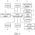
- FIG. 4 is a functional block diagram of the body-worn camera according to a second embodiment of the present invention.
- the body-worn camera of FIG. 4 further includes a speaker S, a vibrator V, and a light-emitting element L (such as a light-emitting diode), and the speaker S, the vibrator V, and the light-emitting element L are electrically connected to the central processing unit 7.
- the central processing unit 7 drives the speaker S to output a prompt sound relevant to the category name, drives the vibrator V to generate vibrations, or drives the light-emitting element L to emit light, or any combination of driving the speaker S to output a prompt sound relevant to the category name, driving the vibrator V to generate vibrations, or driving the light-emitting element L to emit light.
- the central processing unit 7 When the central processing unit 7 receives the category name confirmation signal from the main button 5, the central processing unit 7 drives the speaker S to output a prompt sound relevant to confirmation of the category name, or drives the vibrator V to generate vibrations, or drives the light-emitting element L to emit light, or any combination of the prompt sound, the vibrations, and the light.
- the central processing unit 7 drives the speaker S to output a prompt sound indicating a protracted idle time, or drives the vibrator V to generate vibrations, or drives the light-emitting element L to emit light, or any combination of the prompt sound, the vibrations and the light.
- the displayer 4 of the body-worn camera may be omitted, or the body-worn camera includes any one or any two of the speaker S, the vibrator V, and the light-emitting element L.
- a covert mode knob C is further provided on the casing 1 of the body-worn camera and the covert mode knob C is located outside the turntable 3.
- the covert mode knob C includes three stages of switching. When the covert mode knob C is in a first stage, the speaker S, the vibrator V, the light-emitting element L, and the displayer 4 are disabled. When the covert mode knob C is in a second stage, the speaker S and the light- emitting element L are disabled, and the displayer 4 and the vibrator V are enabled. When the covert mode knob C is in a third stage, the speaker S, the light-emitting element L, the displayer 4, and the vibrator V are enabled.
- FIG. 5 is a flowchart of an operation method of the body-worn camera according to a first embodiment of the present invention.
- the central processing unit 7 receives a video recording trigger signal to instruct the video recording module 2 to start recording a video.
- the body-worn camera enters a video recording mode.
- the main button 5 when the main button 5 is pressed once, the main button 5 sends a video recording trigger signal to the central processing unit 7.
- the body-worn camera may also receive the video recording trigger signal from a remote device through the network communication module 9.
- step S502 the central processing unit 7 receives a stop recording signal to instruct the video recording module 2 to stop recording and to save the video into the memory 8.
- the body-worn camera is switched from the video recording mode to a category mode. For example, when the main button 5 is continuously pressed for a period of time, the main button 5 sends a stop recording signal to the central processing unit 7.
- the body-worn camera may also receive the stop recording signal from the remote device through the network communication module 9.
- step S503 the central processing unit 7 receives a category mode signal from the turntable 3. For example, when the turntable 3 is rotated in a clockwise direction or a counterclockwise direction, the turntable 3 sends the category mode signal to the central processing unit 7.
- step S504 the central processing unit 7 drives the displayer 4 to display a category name.
- step S505 the central processing unit 7 receives a category name confirmation signal from the main button 5, so as to confirm the category name selected by a user. For example, when the displayer 4 displays a speeding incident and the main button 5 is pressed by a user, the central processing unit 7 confirms that the category name is the speeding incident.
- step S506 the central processing unit 7 executes a video tagging program, and the video tagging program saves a corresponding relationship between the selected category name and the video. For example, when the central processing unit 7 confirms that the selected category name is a drunk driving incident, the central processing unit 7 executes the video tagging program saved in the memory 8, and the video tagging program tags the video as the drunk driving incident.
- step S507 the body-worn camera is switched from the category mode to a pre-recording mode.
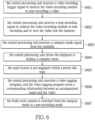
- FIG. 6 is a flowchart of the operation method of the body-worn camera according to a second embodiment of the present invention.
- the central processing unit 7 receives a video recording trigger signal to instruct the video recording module 2 to start recording a video.
- the body-worn camera enters a video recording mode.
- step S602 the central processing unit 7 receives a stop recording signal to instruct the video recording module 2 to stop recording and to save the video into the memory 8. At this time, the body-worn camera is switched from the video recording mode to a category mode.
- step S603 the central processing unit 7 receives a category mode signal from the turntable 3.
- step S604 the central processing unit 7 drives the displayer 4 to display a category name.
- step S605 the main button 5 is not triggered within a preset idle time.
- step S606 the central processing unit 7 executes a video tagging program, and the video tagging program saves a corresponding relationship between an uncategorized name and the video.
- step S607 the body-worn camera is switched from the category mode to a pre-recording mode.
- a default idle time is ten seconds
- the main button 5 is not pressed within ten seconds after the displayer 4 displays a speeding incident
- the video tagging program saves a corresponding relationship between an uncategorized name and the video.
- the body-worn camera is switched from the category mode to the pre-recording mode. Furthermore, each time when the turntable 3 is rotated, the idle time is restarted.
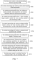
- FIG. 7 is a flowchart of the operation method of the body-worn camera according to a third embodiment of the present invention.
- the body-worn camera in step S701, the body-worn camera is in a pre-recording mode or a privacy mode.
- the central processing unit 7 receives a menu mode signal from the turntable 3. Specifically, when the body-worn camera is in the pre-recording mode or the privacy mode, and the turntable 3 is rotated along a clockwise direction or a counterclockwise direction, the turntable 3 sends a menu mode signal to the central processing unit 7. At this time, the body-worn camera is switched from the pre-recording mode or the privacy mode to a menu mode.
- step S703 the central processing unit 7 drives the displayer 4 to display multiple preset parameters and function operation menus of the body-worn camera.
- These preset parameters include, for example, a speaker volume, a user name, a software version, a remaining space, resolution, transparency, a video storage format, a photo sensor name, a lens focal length, and a denoising level, but the present invention is not limited thereto.
- step S704 the central processing unit 7 receives a video recording trigger signal to instruct the video recording module 2 to start recording a video.
- the body-worn camera is switched from the menu mode to the recording mode.
- the main button 5 sends a video recording trigger signal to the central processing unit 7.
- the central processing unit 7 reads the video recording trigger signal
- the body-worn camera is switched from the menu mode to the video recording mode, and the central processing unit 7 instructs the video recording module 2 to start recording the video.
- step S705 the central processing unit 7 receives a stop recording signal to instruct the video recording module 2 to stop recording and to save the video into the memory 8.
- step S706 the central processing unit 7 receives a category mode signal from the turntable 3.
- step S707 the central processing unit 7 drives the displayer 4 to display a category name.
- step S708 the central processing unit 7 receives a category name confirming signal from the main button 5, so as to confirm the category name selected by a user.
- step S709 the central processing unit 7 executes a video tagging program, and the video tagging program saves a corresponding relationship between the selected category name and the video.
- step S710 the body-worn camera is switched from the category mode to the pre-recording mode.
- FIG. 8 is a flowchart of the operation method of the body-worn camera according to a fourth embodiment of the present invention.
- the body-worn camera in step S801, the body-worn camera is in a pre-recording mode or a privacy mode.
- the central processing unit 7 receives a menu mode signal from the turntable 3. At this time, the body-worn camera is switched from the pre-recording mode or the privacy mode to the menu mode.
- step S803 the central processing unit 7 drives the displayer 4 to display a plurality of preset parameters and function operation menus of the body-worn camera.
- step S804 the central processing unit 7 receives a mode switching signal from the turntable 3, so that the body-worn camera is switched from the menu mode to the pre-recording mode or the privacy mode. Specifically, after the body-worn camera is switched from the pre-recording mode to the menu mode, the body-worn camera may return to the pre-recording mode by the operation of the turntable 3. After the body-worn camera is switched from the privacy mode to the menu mode, the body-worn camera can return to the privacy mode by the operation of the turntable 3.
- FIG. 9 is a flowchart of the operation method of the body-worn camera according to a fifth embodiment of the present invention.
- the body-worn camera in step S901, the body-worn camera is in a pre-recording mode or a privacy mode.
- the central processing unit 7 receives a menu mode signal from the turntable 3. At this time, the body-worn camera is switched from the pre-recording mode or the privacy mode to the menu mode.
- step S903 the central processing unit 7 drives the displayer 4 to display multiple preset parameters and function operation menus of the body-worn camera.
- step S904 the turntable 3 is not triggered within a preset idle time.
- step S905 the body-worn camera is switched from the menu mode to the pre-recording mode or the privacy mode.
- a default idle time is ten seconds. If the turntable 3 is not rotated within ten seconds after the body-worn camera is in the menu mode, the body-worn camera is switched from the menu mode to the pre-recording mode or the privacy mode. Furthermore, each time when the turntable 3 is rotated each time, the idle time is restarted.
- the central processing unit 7 of the body-worn camera receives the recording trigger signal, the body-worn camera that is in the pre-recording mode, the privacy mode, or the menu mode enters the video recording mode.
- the police officer when a police officer finishes using the body-worn camera to record a video relevant to a scene of accident, the police officer may immediately use the body-worn camera to save the corresponding relationship between a category name and the video. In this way, when the police officer returns to a police station after completing his duty, the police officer does not need to spend time using a server to tag the category name for the video, which saves a lot of time and improves efficiency for an on-duty police officer.
Landscapes
- Engineering & Computer Science (AREA)
- Physics & Mathematics (AREA)
- Human Computer Interaction (AREA)
- Theoretical Computer Science (AREA)
- Multimedia (AREA)
- Signal Processing (AREA)
- General Physics & Mathematics (AREA)
- Health & Medical Sciences (AREA)
- Acoustics & Sound (AREA)
- Audiology, Speech & Language Pathology (AREA)
- Computational Linguistics (AREA)
- General Engineering & Computer Science (AREA)
- Computer Hardware Design (AREA)
- Quality & Reliability (AREA)
- Studio Devices (AREA)
- Telephone Function (AREA)
- User Interface Of Digital Computer (AREA)
- Signal Processing For Digital Recording And Reproducing (AREA)
- Television Signal Processing For Recording (AREA)
- Closed-Circuit Television Systems (AREA)
- Slide Switches (AREA)
- Input From Keyboards Or The Like (AREA)
- Switches With Compound Operations (AREA)
- Traffic Control Systems (AREA)
Abstract
Description
- The present invention relates to a video recording device and an operation method thereof, and more particularly to a body-worn camera and an operation method thereof.
- At present, when a police officer is on duty, in order to collect evidence and maintain his own safety, he uses a body-worn camera to record a scene of an incident. When the police officer returns to a police station after completing a task, the police officer connects the body-worn camera to a server in the police station. The police officer then identifies a content of each of recorded videos, and tags each of the recorded videos with a category name through the server. For example, if the content of a video is about a traffic accident, the police officer tags a traffic incident tag on the video through the server.
- However, if the police officer has recorded a large number of videos as a result of a heavy workload, after the police officer completes his duties and returns to the police station, he needs to spend a lot of time tagging the category names for the videos, which is very time-consuming.
- In response to the above-referenced technical inadequacies, the present invention provides a body-worn camera and an operation method thereof.
- In one aspect the present invention provides a body-worn camera. The body-worn camera includes a central processing unit, a video recording module, a turntable, and a main button. The video recording module is electrically connected to the central processing unit. The turntable is electrically connected to the central processing unit. The main button is electrically connected to the central processing unit. After the video recording module completes recording a video, when the central processing unit receives a category mode signal from the turntable and receives a category name confirmation signal from the main button, the central processing unit executes a video tagging program, and the video tagging program saves a corresponding relationship between a category name and the video.
- In another aspect, the present invention provides an operation method of a body-worn camera. The operation method includes: receiving a video recording trigger signal to instruct a video recording module of the body-worn camera to start recording a video; receiving a stop recording signal to instruct the video recording module to stop recording and to complete recording the video; receiving a category mode signal from a turntable of the body-worn camera; receiving a category name confirmation signal from a main button of the body-worn camera; and executing a video tagging program of the body-worn camera, so as to save a corresponding relationship between a category name and the video.
- Therefore, in the body-worn camera and the operation method thereof provided by the present invention, when a police officer finishes using the body-worn camera to record a video relevant to a scene of accident, the police officer may immediately use the body-worn camera to save the corresponding relationship between a category name and the video. In this way, when the police officer returns to a police station after completing his duty, the police officer does not need to spend time using a server to tag the category name for the video, which saves a lot of time and improves efficiency for an on-duty police officer.
- These and other aspects of the present invention will become apparent from the following description of the embodiment taken in conjunction with the following drawings and their captions, although variations and modifications therein may be affected without departing from the spirit and scope of the novel concepts of the invention.
- The described embodiments may be better understood by reference to the following description and the accompanying drawings, in which:
-
FIG. 1 is a schematic diagram of a body-worn camera according to one embodiment of the present invention; -
FIG. 2 is a schematic diagram of the body-worn camera ofFIG. 1 taken in another angle of view; -
FIG. 3 is a functional block diagram of the body-worn camera according to a first embodiment of the present invention; -
FIG. 4 is a functional block diagram of the body-worn camera according to a second embodiment of the present invention; -
FIG. 5 is a flowchart of an operation method of the body-worn camera according to a first embodiment of the present invention; -
FIG. 6 is a flowchart of the operation method of the body-worn camera according to a second embodiment of the present invention; -
FIG. 7 is a flowchart of the operation method of the body-worn camera according to a third embodiment of the present invention; -
FIG. 8 is a flowchart of the operation method of the body-worn camera according to a fourth embodiment of the present invention; and -
FIG. 9 is a flowchart of the operation method of the body-worn camera according to a fifth embodiment of the present invention. - The present invention is more particularly described in the following examples that are intended as illustrative only since numerous modifications and variations therein will be apparent to those skilled in the art. Like numbers in the drawings indicate like components throughout the views. As used in the description herein and throughout the claims that follow, unless the context clearly dictates otherwise, the meaning of "a," "an" and "the" includes plural reference, and the meaning of "in" includes "in" and "on." Titles or subtitles may be used herein for the convenience of a reader, which shall have no influence on the scope of the present invention.
- The terms used herein generally have their ordinary meanings in the art. In the case of conflict, the present document, including any definitions given herein, will prevail. The same thing can be expressed in more than one way. Alternative language and synonyms can be used for any term(s) discussed herein, and no special significance is to be placed upon whether a term is elaborated or discussed herein. A recital of one or more synonyms does not exclude the use of other synonyms. The use of examples anywhere in this specification including examples of any terms is illustrative only, and in no way limits the scope and meaning of the present invention or of any exemplified term. Likewise, the present invention is not limited to various embodiments given herein. Numbering terms such as "first," "second" or "third" can be used to describe various components, signals or the like, which are for distinguishing one component/signal from another one only, and are not intended to, nor should be construed to impose any substantive limitations on the components, signals or the like. In addition, the term "connect" in the context of the present invention means that there is a physical connection between two elements, and the two elements are directly or indirectly connected.
-
FIG. 1 is a schematic diagram of a body-worn camera according to one embodiment of the present invention.FIG. 2 is a schematic diagram of the body-worn camera ofFIG. 1 taken in another angle of view. Referring toFIG. 1 and FIG. 2 , the body-worn camera includes, for example, a casing 1, avideo recording module 2, aturntable 3, adisplayer 4, amain button 5, and anauxiliary button 6, but the present invention is not limited thereto. Thevideo recording module 2 includes, for example, aphotographic lens 21 and amicrophone 22. Thephotographic lens 21, themicrophone 22, theturntable 3, themain button 5, and theauxiliary button 6 are arranged on afirst side 11 of the casing 1, thedisplayer 4 is arranged on asecond side 12 of the casing 1, and thesecond side 12 is adjacent to thefirst side 11. - The
turntable 3 includes a plurality ofoperating portions 31 spaced apart from each other and surround themain button 5, and any two adjacent ones of the plurality ofoperating portions 31 have a same included angle therebetween. In this embodiment, theoperation portions 31 are grooves, but the present invention is not limited thereto. Theoperation portions 31 may also be protrusions or other structures that allow a user to conveniently operate theturntable 3. The casing 1 also has a positioning structure (that is not shown inFIG. 3 ) provided thereon. The positioning structure is provided to fix the position of theturntable 3. If a user wants to rotate theturntable 3, he may exert a force on theturntable 3 to overcome a resistance provided by the positioning structure. The positioning structure includes, for example, a plurality of positioning grooves and a plurality of elastic elements corresponding to theoperating portions 31, but the present invention is not limited thereto. -
FIG. 3 is a functional block diagram of the body-worn camera according to a first embodiment of the present invention. Referring toFIG. 3 , in addition to thevideo recording module 2, theturntable 3, thedisplayer 4, themain button 5, and theauxiliary button 6, the body-worn camera further includes a central processing unit 7, a memory 8, and anetwork communication module 9. The central processing unit 7, the memory 8, and thenetwork communication module 9 are arranged on a circuit board inside the casing 1. Thevideo recording module 2, theturntable 3, thedisplayer 4, themain button 5, theauxiliary button 6, the memory 8, and thenetwork communication module 9 are electrically connected to the central processing unit 7, the memory 8 includes a random-access memory (RAM) and a flash memory, and the body-worn camera may communicate with a remote device by using thenetwork communication module 9. - The body-worn camera is generally in a pre-recording mode or a privacy mode. Specifically, when the body-worn camera is in the pre-recording mode and the central processing unit 7 does not receive a video recording trigger signal, the
video recording module 2 continuously records a video. Conversely, when the body-worn camera is in the privacy mode and the central processing unit 7 does not receive the video recording trigger signal, thevideo recording module 2 does not record a video. - When the body-worn camera is in the pre-recording mode and the
auxiliary button 6 is triggered, the central processing unit 7 receives a mode switching signal from theauxiliary button 6, so that the body-worn camera switches from the pre-recording mode to the privacy mode. Conversely, when the body-worn camera is in the privacy mode and theauxiliary button 6 is triggered, the central processing unit 7 receives the mode switching signal from theauxiliary button 6, so that the body-worn camera is switched from the privacy mode to the pre-recording mode. Theauxiliary button 6 can be triggered by, for example, being pressed once or being continuously pressed for several seconds, but the present invention is not limited thereto. - When the central processing unit 7 of the body-worn camera in the pre-recording mode or the privacy mode receives a video recording trigger signal, the central processing unit 7 instructs the
video recording module 2 to start recording. At this time, the body-worn camera is switched from the pre-recording mode to a video recording mode. When the video recording mode of the body-worn camera continues for a period of time and the central processing unit 7 of the body-worn camera receives a stop recording signal, the central processing unit 7 instructs thevideo recording module 2 to stop recording and to save a recorded video into the memory 8. At this time, the body-worn camera is switched from the video recording mode to a category mode. - A plurality of different category names (not shown in the figures) are saved in the memory 8, and these category names include, for example, a robbery incident, a traffic incident, a speeding incident, a drunk driving incident, a fighting incident, and a homicide incident, but the present invention is not limited thereto.
- For example, when the body-worn camera is in the category mode and a user rotates one of the operating
portions 31 of theturntable 3 by a first angle in the clockwise direction, theturntable 3 is triggered and the central processing unit 7 receives a category mode signal from theturntable 3 such that the central processing unit 7 drives thedisplayer 4 to display a first category name (such as a robbery incident). When the user rotates the operatingportion 31 of theturntable 3 by a second angle that can be twice the first angle in the clockwise direction, the central processing unit 7 receives the category mode signal from theturntable 3 and the central processing unit 7 drives thedisplayer 4 to display a second category name (such as a traffic incident). That is, when theturntable 3 is rotated by different angles, thedisplayer 4 displays different category names. When thedisplayer 4 displays the second category name and theturntable 3 is rotated in a counterclockwise direction, thedisplayer 4 displays the first category name. - When the
displayer 4 displays the category name and themain button 5 is triggered, the central processing unit 7 receives a category name confirmation signal from themain button 5. Themain button 5 can be triggered by, for example, being pressed once or being continuously pressed for several seconds, but the present invention is not limited thereto. - After the central processing unit 7 receives the category name confirmation signal, the central processing unit 7 executes a video tagging program (not shown in the figures) saved in the memory 8, and the video tagging program saves a corresponding relationship between the category name and the video.
-
FIG. 4 is a functional block diagram of the body-worn camera according to a second embodiment of the present invention. Compared with the body-worn camera ofFIG. 1 , the body-worn camera ofFIG. 4 further includes a speaker S, a vibrator V, and a light-emitting element L (such as a light-emitting diode), and the speaker S, the vibrator V, and the light-emitting element L are electrically connected to the central processing unit 7. When thedisplayer 4 displays the category name, the central processing unit 7 drives the speaker S to output a prompt sound relevant to the category name, drives the vibrator V to generate vibrations, or drives the light-emitting element L to emit light, or any combination of driving the speaker S to output a prompt sound relevant to the category name, driving the vibrator V to generate vibrations, or driving the light-emitting element L to emit light. - When the central processing unit 7 receives the category name confirmation signal from the
main button 5, the central processing unit 7 drives the speaker S to output a prompt sound relevant to confirmation of the category name, or drives the vibrator V to generate vibrations, or drives the light-emitting element L to emit light, or any combination of the prompt sound, the vibrations, and the light. - After the
displayer 4 displays the category name, when themain button 5 is not triggered within a preset idle time, the central processing unit 7 drives the speaker S to output a prompt sound indicating a protracted idle time, or drives the vibrator V to generate vibrations, or drives the light-emitting element L to emit light, or any combination of the prompt sound, the vibrations and the light. - In other embodiments, the
displayer 4 of the body-worn camera may be omitted, or the body-worn camera includes any one or any two of the speaker S, the vibrator V, and the light-emitting element L. - Referring to
FIG. 1 andFIG. 4 , a covert mode knob C is further provided on the casing 1 of the body-worn camera and the covert mode knob C is located outside theturntable 3. The covert mode knob C includes three stages of switching. When the covert mode knob C is in a first stage, the speaker S, the vibrator V, the light-emitting element L, and thedisplayer 4 are disabled. When the covert mode knob C is in a second stage, the speaker S and the light- emitting element L are disabled, and thedisplayer 4 and the vibrator V are enabled. When the covert mode knob C is in a third stage, the speaker S, the light-emitting element L, thedisplayer 4, and the vibrator V are enabled. -
FIG. 5 is a flowchart of an operation method of the body-worn camera according to a first embodiment of the present invention. Referring toFIG. 5 , in step S501, the central processing unit 7 receives a video recording trigger signal to instruct thevideo recording module 2 to start recording a video. At this time, the body-worn camera enters a video recording mode. For example, when themain button 5 is pressed once, themain button 5 sends a video recording trigger signal to the central processing unit 7. In addition, the body-worn camera may also receive the video recording trigger signal from a remote device through thenetwork communication module 9. - In step S502, the central processing unit 7 receives a stop recording signal to instruct the
video recording module 2 to stop recording and to save the video into the memory 8. At this time, the body-worn camera is switched from the video recording mode to a category mode. For example, when themain button 5 is continuously pressed for a period of time, themain button 5 sends a stop recording signal to the central processing unit 7. Similarly, the body-worn camera may also receive the stop recording signal from the remote device through thenetwork communication module 9. - In step S503, the central processing unit 7 receives a category mode signal from the
turntable 3. For example, when theturntable 3 is rotated in a clockwise direction or a counterclockwise direction, theturntable 3 sends the category mode signal to the central processing unit 7. - In step S504, the central processing unit 7 drives the
displayer 4 to display a category name. - In step S505, the central processing unit 7 receives a category name confirmation signal from the
main button 5, so as to confirm the category name selected by a user. For example, when thedisplayer 4 displays a speeding incident and themain button 5 is pressed by a user, the central processing unit 7 confirms that the category name is the speeding incident. - In step S506, the central processing unit 7 executes a video tagging program, and the video tagging program saves a corresponding relationship between the selected category name and the video. For example, when the central processing unit 7 confirms that the selected category name is a drunk driving incident, the central processing unit 7 executes the video tagging program saved in the memory 8, and the video tagging program tags the video as the drunk driving incident.
- In step S507, the body-worn camera is switched from the category mode to a pre-recording mode.
-
FIG. 6 is a flowchart of the operation method of the body-worn camera according to a second embodiment of the present invention. Referring toFIG. 6 , in step S601, the central processing unit 7 receives a video recording trigger signal to instruct thevideo recording module 2 to start recording a video. At this time, the body-worn camera enters a video recording mode. - In step S602, the central processing unit 7 receives a stop recording signal to instruct the
video recording module 2 to stop recording and to save the video into the memory 8. At this time, the body-worn camera is switched from the video recording mode to a category mode. - In step S603, the central processing unit 7 receives a category mode signal from the
turntable 3. - In step S604, the central processing unit 7 drives the
displayer 4 to display a category name. - In step S605, the
main button 5 is not triggered within a preset idle time. - In step S606, the central processing unit 7 executes a video tagging program, and the video tagging program saves a corresponding relationship between an uncategorized name and the video.
- In step S607, the body-worn camera is switched from the category mode to a pre-recording mode.
- For example, a default idle time is ten seconds, if the
main button 5 is not pressed within ten seconds after thedisplayer 4 displays a speeding incident, the video tagging program saves a corresponding relationship between an uncategorized name and the video. Subsequently, the body-worn camera is switched from the category mode to the pre-recording mode. Furthermore, each time when theturntable 3 is rotated, the idle time is restarted. -
FIG. 7 is a flowchart of the operation method of the body-worn camera according to a third embodiment of the present invention. Referring toFIG. 7 , in step S701, the body-worn camera is in a pre-recording mode or a privacy mode. In step S702, the central processing unit 7 receives a menu mode signal from theturntable 3. Specifically, when the body-worn camera is in the pre-recording mode or the privacy mode, and theturntable 3 is rotated along a clockwise direction or a counterclockwise direction, theturntable 3 sends a menu mode signal to the central processing unit 7. At this time, the body-worn camera is switched from the pre-recording mode or the privacy mode to a menu mode. - In step S703, the central processing unit 7 drives the
displayer 4 to display multiple preset parameters and function operation menus of the body-worn camera. These preset parameters include, for example, a speaker volume, a user name, a software version, a remaining space, resolution, transparency, a video storage format, a photo sensor name, a lens focal length, and a denoising level, but the present invention is not limited thereto. - In step S704, the central processing unit 7 receives a video recording trigger signal to instruct the
video recording module 2 to start recording a video. At this time, the body-worn camera is switched from the menu mode to the recording mode. For example, when the body-worn camera is in the menu mode and themain button 5 is pressed, themain button 5 sends a video recording trigger signal to the central processing unit 7. When the central processing unit 7 reads the video recording trigger signal, the body-worn camera is switched from the menu mode to the video recording mode, and the central processing unit 7 instructs thevideo recording module 2 to start recording the video. - In step S705, the central processing unit 7 receives a stop recording signal to instruct the
video recording module 2 to stop recording and to save the video into the memory 8. - In step S706, the central processing unit 7 receives a category mode signal from the
turntable 3. - In step S707, the central processing unit 7 drives the
displayer 4 to display a category name. - In step S708, the central processing unit 7 receives a category name confirming signal from the
main button 5, so as to confirm the category name selected by a user. - In step S709, the central processing unit 7 executes a video tagging program, and the video tagging program saves a corresponding relationship between the selected category name and the video.
- In step S710, the body-worn camera is switched from the category mode to the pre-recording mode.
-
FIG. 8 is a flowchart of the operation method of the body-worn camera according to a fourth embodiment of the present invention. Referring toFIG. 8 , in step S801, the body-worn camera is in a pre-recording mode or a privacy mode. In step S802, the central processing unit 7 receives a menu mode signal from theturntable 3. At this time, the body-worn camera is switched from the pre-recording mode or the privacy mode to the menu mode. - In step S803, the central processing unit 7 drives the
displayer 4 to display a plurality of preset parameters and function operation menus of the body-worn camera. - In step S804, the central processing unit 7 receives a mode switching signal from the
turntable 3, so that the body-worn camera is switched from the menu mode to the pre-recording mode or the privacy mode. Specifically, after the body-worn camera is switched from the pre-recording mode to the menu mode, the body-worn camera may return to the pre-recording mode by the operation of theturntable 3. After the body-worn camera is switched from the privacy mode to the menu mode, the body-worn camera can return to the privacy mode by the operation of theturntable 3. -
FIG. 9 is a flowchart of the operation method of the body-worn camera according to a fifth embodiment of the present invention. Referring toFIG. 9 , in step S901, the body-worn camera is in a pre-recording mode or a privacy mode. In step S902, the central processing unit 7 receives a menu mode signal from theturntable 3. At this time, the body-worn camera is switched from the pre-recording mode or the privacy mode to the menu mode. - In step S903, the central processing unit 7 drives the
displayer 4 to display multiple preset parameters and function operation menus of the body-worn camera. - In step S904, the
turntable 3 is not triggered within a preset idle time. - In step S905, the body-worn camera is switched from the menu mode to the pre-recording mode or the privacy mode.
- For example, a default idle time is ten seconds. If the
turntable 3 is not rotated within ten seconds after the body-worn camera is in the menu mode, the body-worn camera is switched from the menu mode to the pre-recording mode or the privacy mode. Furthermore, each time when theturntable 3 is rotated each time, the idle time is restarted. - In addition, when the central processing unit 7 of the body-worn camera receives the recording trigger signal, the body-worn camera that is in the pre-recording mode, the privacy mode, or the menu mode enters the video recording mode.
- In conclusion, in the body-worn camera and the operation method thereof provided by the present invention, when a police officer finishes using the body-worn camera to record a video relevant to a scene of accident, the police officer may immediately use the body-worn camera to save the corresponding relationship between a category name and the video. In this way, when the police officer returns to a police station after completing his duty, the police officer does not need to spend time using a server to tag the category name for the video, which saves a lot of time and improves efficiency for an on-duty police officer.
- The foregoing description of the exemplary embodiments of the invention has been presented only for the purposes of illustration and description and is not intended to be exhaustive or to limit the invention to the precise forms disclosed. Many modifications and variations are possible in light of the above teaching.
Claims (10)
- A body-worn camera, characterized by comprising:a central processing unit (7);a video recording module (2) electrically connected to the central processing unit (7);a turntable (3) electrically connected to the central processing unit (7); anda main button (5) electrically connected to the central processing unit (7);wherein, after the video recording module (2) completes recording a video, when the central processing unit (7) receives a category mode signal from the turntable (3) and receives a category name confirmation signal from the main button (5), the central processing unit (7) executes a video tagging program, and the video tagging program saves a corresponding relationship between a category name and the video.
- The body-worn camera according to claim 1, wherein, when the turntable (3) is rotated by a first angle, the central processing unit (7) receives the category mode signal, and the category name is a first category name; wherein, when the turntable (3) is rotated by a second angle, the central processing unit (7) receives the category mode signal, and the category name is a second category name; wherein the first angle is different from the second angle, and the first category name is different from the second category name.
- The body-worn camera according to claim 1, wherein, when the body-worn camera is in a pre-recording mode or a privacy mode and the central processing unit (7) receives a menu mode signal from the turntable (3), the body-worn camera switches from the pre-recording mode or the privacy mode to a menu mode.
- The body-worn camera according to claim 1, further comprising a displayer (4), wherein the displayer (4) is electrically connected to the central processing unit (7); wherein, when the central processing unit (7) receives the category mode signal from the turntable (3), the displayer (4) displays the category name; wherein, when the displayer (4) displays the category name and the main button (5) is not triggered, the central processing unit (7) executes the video tagging program, and the video tagging program saves a corresponding relationship between an uncategorized name and the video.
- The body-worn camera according to claim 4, further comprising a speaker (S), a vibrator (V), and a light-emitting element (L), wherein the speaker (S), the vibrator (V) and the light-emitting element (L) are electrically connected to the central processing unit (7), and wherein, when the displayer (4) displays the category name, the speaker (S) outputs a prompt sound, the vibrator (V) generates vibration, or the light-emitting element (L) emits light.
- An operation method of a body-worn camera, characterized by comprising:receiving a video recording trigger signal to instruct a video recording module (2) of the body-worn camera to start recording a video;receiving a stop recording signal to instruct the video recording module (2) to stop recording and to complete recording the video;receiving a category mode signal from a turntable (3) of the body-worn camera;receiving a category name confirmation signal from a main button (5) of the body-worn camera; andexecuting a video tagging program of the body-worn camera, so as to save a corresponding relationship between a category name and the video.
- The operation method according to claim 6, further comprising: driving a displayer (4) of the body-worn camera to display the category name, wherein, when the displayer (4) displays the category name and the main button (5) is not triggered, a central processing unit (7) executes the video tagging program so as to save a corresponding relationship between an uncategorized name and the video.
- The operation method according to claim 7, further comprising: switching the body-worn camera from a category mode to a pre-recording mode after the video tagging program saves the corresponding relationship between the uncategorized name and the video.
- The operation method according to claim 6, wherein, when the body-worn camera is in a pre-recording mode or a privacy mode and a central processing unit (7) receives a menu mode signal from the turntable (3), the body-worn camera switches from the pre-recording mode or the privacy mode to a menu mode.
- The operation method according to claim 9, wherein, when the body-worn camera is in the pre-recording mode, the privacy mode, or the menu mode, and the central processing unit (7) receives the video recording trigger signal, the body-worn camera enters a video recording mode.
Applications Claiming Priority (2)
| Application Number | Priority Date | Filing Date | Title |
|---|---|---|---|
| US202263423453P | 2022-11-07 | 2022-11-07 | |
| US202363449272P | 2023-03-01 | 2023-03-01 |
Publications (1)
| Publication Number | Publication Date |
|---|---|
| EP4365893A1 true EP4365893A1 (en) | 2024-05-08 |
Family
ID=86604778
Family Applications (4)
| Application Number | Title | Priority Date | Filing Date |
|---|---|---|---|
| EP23175301.3A Pending EP4365892A1 (en) | 2022-11-07 | 2023-05-25 | Voice activity detection device and method |
| EP23188628.4A Pending EP4365705A1 (en) | 2022-11-07 | 2023-07-31 | Operation-indication mode switching structure, circuit and method for operating the same |
| EP23189417.1A Pending EP4365893A1 (en) | 2022-11-07 | 2023-08-03 | Body-worn camera and operation method thereof |
| EP23202395.2A Pending EP4365899A1 (en) | 2022-11-07 | 2023-10-09 | Memory management method for continuously recording digital content and circuit system thereof |
Family Applications Before (2)
| Application Number | Title | Priority Date | Filing Date |
|---|---|---|---|
| EP23175301.3A Pending EP4365892A1 (en) | 2022-11-07 | 2023-05-25 | Voice activity detection device and method |
| EP23188628.4A Pending EP4365705A1 (en) | 2022-11-07 | 2023-07-31 | Operation-indication mode switching structure, circuit and method for operating the same |
Family Applications After (1)
| Application Number | Title | Priority Date | Filing Date |
|---|---|---|---|
| EP23202395.2A Pending EP4365899A1 (en) | 2022-11-07 | 2023-10-09 | Memory management method for continuously recording digital content and circuit system thereof |
Country Status (3)
| Country | Link |
|---|---|
| US (5) | US12393334B2 (en) |
| EP (4) | EP4365892A1 (en) |
| TW (5) | TWI852489B (en) |
Families Citing this family (3)
| Publication number | Priority date | Publication date | Assignee | Title |
|---|---|---|---|---|
| TWI852489B (en) * | 2022-11-07 | 2024-08-11 | 神基科技股份有限公司 | Voice activity detection device and method |
| US20250251902A1 (en) * | 2024-02-07 | 2025-08-07 | SuperScope Technologies Inc. | Record Check |
| JP7665249B1 (en) * | 2024-10-25 | 2025-04-21 | Matsuo Sangyoグループ株式会社 | Camera System |
Citations (3)
| Publication number | Priority date | Publication date | Assignee | Title |
|---|---|---|---|---|
| US20160196693A1 (en) * | 2015-01-06 | 2016-07-07 | Seiko Epson Corporation | Display system, control method for display device, and computer program |
| US20160227173A1 (en) * | 2015-01-29 | 2016-08-04 | Panasonic Intellectual Property Management Co., Ltd. | Wearable camera system, and video recording control method for wearable camera system |
| US10446183B2 (en) * | 2008-04-06 | 2019-10-15 | Taser International, Inc. | Systems and methods for a recorder user interface |
Family Cites Families (60)
| Publication number | Priority date | Publication date | Assignee | Title |
|---|---|---|---|---|
| JPH0675588A (en) | 1992-08-27 | 1994-03-18 | Fujitsu Ltd | Speech recognition device |
| US5418762A (en) * | 1992-12-09 | 1995-05-23 | Sony Corporation | Optical disk recording device having a pre-recording mode |
| US6519003B1 (en) | 1998-03-26 | 2003-02-11 | Eastman Kodak Company | Camera with combination four-way directional and mode control interface |
| US6563532B1 (en) * | 1999-01-05 | 2003-05-13 | Internal Research Corporation | Low attention recording unit for use by vigorously active recorder |
| US7155735B1 (en) | 1999-10-08 | 2006-12-26 | Vulcan Patents Llc | System and method for the broadcast dissemination of time-ordered data |
| JP4101421B2 (en) | 1999-12-27 | 2008-06-18 | 富士フイルム株式会社 | INPUT UNIT, INFORMATION RECORDING DEVICE USING INPUT UNIT, AND DIGITAL CAMERA |
| JP4620894B2 (en) * | 2001-04-06 | 2011-01-26 | キヤノン株式会社 | Electronics |
| US6957397B1 (en) * | 2001-06-11 | 2005-10-18 | Palm, Inc. | Navigating through a menu of a handheld computer using a keyboard |
| TWI225369B (en) * | 2003-03-18 | 2004-12-11 | Jin-Shu Chen | Diversified video recording apparatus |
| US20040212637A1 (en) | 2003-04-22 | 2004-10-28 | Kivin Varghese | System and Method for Marking and Tagging Wireless Audio and Video Recordings |
| US7023004B2 (en) | 2003-10-23 | 2006-04-04 | Timothy Ford | Multi-mode electromagnetic radiation emitting device |
| US20050147397A1 (en) * | 2003-12-17 | 2005-07-07 | Sony Corporation | Image pickup apparatus |
| KR20050090798A (en) | 2004-03-10 | 2005-09-14 | 삼성전자주식회사 | Switching apparatus of photographing device for selecting mode |
| JP4379800B2 (en) * | 2004-07-12 | 2009-12-09 | ソニー・エリクソン・モバイルコミュニケーションズ株式会社 | Receiving apparatus and memory releasing method thereof |
| JP2006040382A (en) * | 2004-07-27 | 2006-02-09 | Sony Corp | Digital data recording apparatus and recording method |
| TWI245191B (en) * | 2004-09-14 | 2005-12-11 | Ali Corp | Sound receiving and pre-recording device and method |
| US20060085834A1 (en) * | 2004-10-19 | 2006-04-20 | Cayin Technology Co., Ltd. | System and method for transmitting multi-channel signals |
| US9209995B2 (en) * | 2006-12-29 | 2015-12-08 | Prodea Systems, Inc. | Presence status notification from digital endpoint devices through a multi-services gateway device at the user premises |
| US8140325B2 (en) * | 2007-01-04 | 2012-03-20 | International Business Machines Corporation | Systems and methods for intelligent control of microphones for speech recognition applications |
| US8209728B2 (en) | 2007-08-31 | 2012-06-26 | At&T Intellectual Property I, L.P. | System and method of delivering video content |
| JP5075664B2 (en) * | 2008-02-15 | 2012-11-21 | 株式会社東芝 | Spoken dialogue apparatus and support method |
| US8872940B2 (en) * | 2008-03-03 | 2014-10-28 | Videoiq, Inc. | Content aware storage of video data |
| TWI402718B (en) * | 2008-07-01 | 2013-07-21 | Inventec Corp | Electronic device and operation method thereof |
| US10737185B2 (en) * | 2009-03-18 | 2020-08-11 | Microsoft Technology Licensing, Llc | Virtual environment controls based on voice chat audio inputs |
| ES2903148T3 (en) | 2010-09-13 | 2022-03-31 | Contour Ip Holding Llc | Portable digital video camera configured for remote image acquisition control and viewing |
| JP6088733B2 (en) | 2011-11-29 | 2017-03-01 | オリンパス株式会社 | Imaging device |
| JP5189221B1 (en) * | 2012-03-13 | 2013-04-24 | シャープ株式会社 | CONTENT DISPLAY DEVICE, TELEVISION RECEIVER, MENU SCREEN GENERATION METHOD, PROGRAM, AND RECORDING MEDIUM |
| TW201414274A (en) * | 2012-09-21 | 2014-04-01 | Hon Hai Prec Ind Co Ltd | Sound effect managing system and sound effect managing method |
| US9019431B2 (en) * | 2012-09-28 | 2015-04-28 | Digital Ally, Inc. | Portable video and imaging system |
| US20140104493A1 (en) * | 2012-10-11 | 2014-04-17 | Tangome, Inc. | Proactive video frame dropping for hardware and network variance |
| US9706101B2 (en) * | 2012-10-22 | 2017-07-11 | Sony Corporation | Image processing terminal, imaging machine, information processing method, program, and remote imaging system to remotely operate the imaging machine |
| US9329833B2 (en) * | 2013-12-20 | 2016-05-03 | Dell Products, L.P. | Visual audio quality cues and context awareness in a virtual collaboration session |
| TWI516950B (en) | 2013-12-23 | 2016-01-11 | 勝捷光電股份有限公司 | System and method for sharing real-time recording |
| KR102164798B1 (en) | 2014-09-11 | 2020-10-13 | 삼성전자 주식회사 | Display driving circuit and display device comprising the same |
| WO2016088919A1 (en) * | 2014-12-04 | 2016-06-09 | (주) 트라이너스 | Wireless microphone system |
| US9661283B2 (en) | 2014-12-24 | 2017-05-23 | Panasonic Intellectual Property Management Co., Ltd. | Wearable camera |
| US20160286156A1 (en) | 2015-02-12 | 2016-09-29 | Creative Law Enforcement Resources, Inc. | System for managing information related to recordings from video/audio recording devices |
| TWI550612B (en) | 2015-03-23 | 2016-09-21 | 群聯電子股份有限公司 | Data programming method, memory storage device and memory controlling circuit unit |
| CN105045473A (en) * | 2015-07-01 | 2015-11-11 | 沈波 | Human-computer interaction system and method |
| CN105120063A (en) | 2015-07-13 | 2015-12-02 | 联想(北京)有限公司 | Volume prompting method of input voice and electronic device |
| US20170094231A1 (en) * | 2015-09-29 | 2017-03-30 | Faraday&Future Inc. | Scene reconstruction using pre-buffering in sensor triggered automobile cameras |
| US9697884B2 (en) * | 2015-10-08 | 2017-07-04 | Rambus Inc. | Variable width memory module supporting enhanced error detection and correction |
| US10812894B2 (en) | 2016-12-23 | 2020-10-20 | Motorola Solutions, Inc. | Portable communication device and method of operating the same in covert operation mode |
| JP6553111B2 (en) * | 2017-03-21 | 2019-07-31 | 株式会社東芝 | Speech recognition apparatus, speech recognition method and speech recognition program |
| JP6894736B2 (en) * | 2017-03-24 | 2021-06-30 | キヤノン株式会社 | Recording device, control method, and program |
| CN107291341B (en) * | 2017-07-11 | 2021-03-09 | 广州飞傲电子科技有限公司 | Method and system for selecting music player through touch turntable rotation |
| CN109548080B (en) * | 2017-08-11 | 2023-05-16 | 夏普株式会社 | Related method, user equipment and base station for media access control layer grouping |
| CN108320742B (en) * | 2018-01-31 | 2021-09-14 | 广东美的制冷设备有限公司 | Voice interaction method, intelligent device and storage medium |
| US20190266881A1 (en) | 2018-02-25 | 2019-08-29 | Laura Gasparis Vonfrolio | System and method for an alert and crisis/emergency management system |
| CN108668017A (en) | 2018-04-19 | 2018-10-16 | Oppo广东移动通信有限公司 | Volume prompting method, mode switching method, device, terminal and storage medium |
| CN110750491A (en) | 2018-07-06 | 2020-02-04 | 神讯电脑(昆山)有限公司 | Setting method of information capture device |
| CN110858493A (en) | 2018-08-23 | 2020-03-03 | 神讯电脑(昆山)有限公司 | information capture device |
| CN110881076A (en) * | 2018-09-06 | 2020-03-13 | 上海伴我科技有限公司 | Terminal communication device |
| TW202113561A (en) * | 2019-09-20 | 2021-04-01 | 和碩聯合科技股份有限公司 | Notebook computer and operation method thereof |
| US11490204B2 (en) * | 2020-07-20 | 2022-11-01 | Apple Inc. | Multi-device audio adjustment coordination |
| JP2022022152A (en) * | 2020-07-24 | 2022-02-03 | シンクウェア コーポレーション | Electronic device and method for determining lifespan and failure of nonvolatile memory storage device |
| TW202205143A (en) | 2020-07-30 | 2022-02-01 | 杰悉科技股份有限公司 | Image object labeling method |
| US11489996B2 (en) * | 2021-03-31 | 2022-11-01 | Johnny Burton | Wireless earpiece camera apparatus |
| US11950017B2 (en) * | 2022-05-17 | 2024-04-02 | Digital Ally, Inc. | Redundant mobile video recording |
| TWI852489B (en) * | 2022-11-07 | 2024-08-11 | 神基科技股份有限公司 | Voice activity detection device and method |
-
2023
- 2023-04-20 TW TW112114808A patent/TWI852489B/en active
- 2023-05-16 US US18/318,649 patent/US12393334B2/en active Active
- 2023-05-25 EP EP23175301.3A patent/EP4365892A1/en active Pending
- 2023-06-07 TW TW112121198A patent/TWI882349B/en active
- 2023-06-07 TW TW112121192A patent/TWI832774B/en active
- 2023-07-11 US US18/350,707 patent/US12353710B2/en active Active
- 2023-07-18 US US18/354,552 patent/US12554396B2/en active Active
- 2023-07-31 EP EP23188628.4A patent/EP4365705A1/en active Pending
- 2023-08-03 EP EP23189417.1A patent/EP4365893A1/en active Pending
- 2023-08-08 TW TW112129654A patent/TWI841470B/en active
- 2023-10-09 EP EP23202395.2A patent/EP4365899A1/en active Pending
- 2023-10-11 US US18/484,594 patent/US12360668B2/en active Active
- 2023-11-07 TW TW112142737A patent/TWI906690B/en active
-
2025
- 2025-06-27 US US19/252,206 patent/US20250328241A1/en active Pending
Patent Citations (3)
| Publication number | Priority date | Publication date | Assignee | Title |
|---|---|---|---|---|
| US10446183B2 (en) * | 2008-04-06 | 2019-10-15 | Taser International, Inc. | Systems and methods for a recorder user interface |
| US20160196693A1 (en) * | 2015-01-06 | 2016-07-07 | Seiko Epson Corporation | Display system, control method for display device, and computer program |
| US20160227173A1 (en) * | 2015-01-29 | 2016-08-04 | Panasonic Intellectual Property Management Co., Ltd. | Wearable camera system, and video recording control method for wearable camera system |
Also Published As
| Publication number | Publication date |
|---|---|
| US12393334B2 (en) | 2025-08-19 |
| EP4365705A1 (en) | 2024-05-08 |
| US20240153719A1 (en) | 2024-05-09 |
| US12360668B2 (en) | 2025-07-15 |
| TWI832774B (en) | 2024-02-11 |
| TW202420296A (en) | 2024-05-16 |
| EP4365892A1 (en) | 2024-05-08 |
| TW202420219A (en) | 2024-05-16 |
| TWI882349B (en) | 2025-05-01 |
| US20240152273A1 (en) | 2024-05-09 |
| EP4365899A1 (en) | 2024-05-08 |
| TW202420038A (en) | 2024-05-16 |
| TWI906690B (en) | 2025-12-01 |
| US20240155082A1 (en) | 2024-05-09 |
| US20240153530A1 (en) | 2024-05-09 |
| TW202420042A (en) | 2024-05-16 |
| TWI841470B (en) | 2024-05-01 |
| TWI852489B (en) | 2024-08-11 |
| US12353710B2 (en) | 2025-07-08 |
| TW202420801A (en) | 2024-05-16 |
| US12554396B2 (en) | 2026-02-17 |
| US20250328241A1 (en) | 2025-10-23 |
Similar Documents
| Publication | Publication Date | Title |
|---|---|---|
| US12353710B2 (en) | Body-worn camera and operation method thereof | |
| JP6503148B1 (en) | Cross-referencing of applications related to sharing of video images from audio / video recording and communication devices | |
| KR101882442B1 (en) | Mobile terminal, server, method for controlling of the mobile terminal, mehtod for controlling of the server | |
| CN112768027A (en) | Detection result query method, device, terminal, server and storage medium | |
| CN111712807B (en) | Portable information terminal, information prompting system and information prompting method | |
| KR20070089919A (en) | Enhanced contextual user assistance | |
| CN114900559A (en) | Management system, terminal, management method, and storage medium | |
| US12361055B2 (en) | Picture search method and device | |
| CN113808343A (en) | Method and electronic device for storing book information | |
| CN117998036A (en) | Body-worn camera and method of operating the same | |
| KR101449862B1 (en) | Photographing apparatus, control method, and recording medium thereof for matching and saving photograph and voice recognition information | |
| US20110316822A1 (en) | Image display device | |
| JP2018137683A (en) | Report support system, portable terminal, report support method and program | |
| JP4649944B2 (en) | Moving image processing apparatus, moving image processing method, and program | |
| CN114078582B (en) | Service information association method, device, terminal and storage medium | |
| KR101189913B1 (en) | Method and Apparatus for Managing Customer | |
| JP2005111987A (en) | User interfaces for printers and network printers | |
| US20190180042A1 (en) | Image display device, image display control device, and image display control method | |
| CN115776541B (en) | Call processing method, device, equipment and storage medium | |
| CN114648315A (en) | Virtual interview method, device, equipment and storage medium | |
| KR100463316B1 (en) | Automated Image Pick up System | |
| CN114579942B (en) | Data management method, system and storage medium | |
| CN117407446A (en) | Data quality detection system, method, terminal and server | |
| KR102144492B1 (en) | Image Memorizing and Checking Smart Terminal by Using Voice Data and Method Thereof | |
| JP3183220B2 (en) | Digital camera image comment input device |
Legal Events
| Date | Code | Title | Description |
|---|---|---|---|
| PUAI | Public reference made under article 153(3) epc to a published international application that has entered the european phase |
Free format text: ORIGINAL CODE: 0009012 |
|
| STAA | Information on the status of an ep patent application or granted ep patent |
Free format text: STATUS: THE APPLICATION HAS BEEN PUBLISHED |
|
| AK | Designated contracting states |
Kind code of ref document: A1 Designated state(s): AL AT BE BG CH CY CZ DE DK EE ES FI FR GB GR HR HU IE IS IT LI LT LU LV MC ME MK MT NL NO PL PT RO RS SE SI SK SM TR |
|
| STAA | Information on the status of an ep patent application or granted ep patent |
Free format text: STATUS: REQUEST FOR EXAMINATION WAS MADE |
|
| 17P | Request for examination filed |
Effective date: 20240912 |
|
| RBV | Designated contracting states (corrected) |
Designated state(s): AL AT BE BG CH CY CZ DE DK EE ES FI FR GB GR HR HU IE IS IT LI LT LU LV MC ME MK MT NL NO PL PT RO RS SE SI SK SM TR |
|
| STAA | Information on the status of an ep patent application or granted ep patent |
Free format text: STATUS: EXAMINATION IS IN PROGRESS |
|
| 17Q | First examination report despatched |
Effective date: 20251103 |