EP4365624A1 - Detection and classification of moving objects in radar data using deep learning - Google Patents
Detection and classification of moving objects in radar data using deep learning Download PDFInfo
- Publication number
- EP4365624A1 EP4365624A1 EP22205511.3A EP22205511A EP4365624A1 EP 4365624 A1 EP4365624 A1 EP 4365624A1 EP 22205511 A EP22205511 A EP 22205511A EP 4365624 A1 EP4365624 A1 EP 4365624A1
- Authority
- EP
- European Patent Office
- Prior art keywords
- objects
- computer
- detection
- implemented method
- sub
- Prior art date
- Legal status (The legal status is an assumption and is not a legal conclusion. Google has not performed a legal analysis and makes no representation as to the accuracy of the status listed.)
- Withdrawn
Links
Images


Classifications
-
- G—PHYSICS
- G01—MEASURING; TESTING
- G01S—RADIO DIRECTION-FINDING; RADIO NAVIGATION; DETERMINING DISTANCE OR VELOCITY BY USE OF RADIO WAVES; LOCATING OR PRESENCE-DETECTING BY USE OF THE REFLECTION OR RERADIATION OF RADIO WAVES; ANALOGOUS ARRANGEMENTS USING OTHER WAVES
- G01S7/00—Details of systems according to groups G01S13/00, G01S15/00, G01S17/00
- G01S7/02—Details of systems according to groups G01S13/00, G01S15/00, G01S17/00 of systems according to group G01S13/00
- G01S7/41—Details of systems according to groups G01S13/00, G01S15/00, G01S17/00 of systems according to group G01S13/00 using analysis of echo signal for target characterisation; Target signature; Target cross-section
- G01S7/417—Details of systems according to groups G01S13/00, G01S15/00, G01S17/00 of systems according to group G01S13/00 using analysis of echo signal for target characterisation; Target signature; Target cross-section involving the use of neural networks
-
- G—PHYSICS
- G01—MEASURING; TESTING
- G01S—RADIO DIRECTION-FINDING; RADIO NAVIGATION; DETERMINING DISTANCE OR VELOCITY BY USE OF RADIO WAVES; LOCATING OR PRESENCE-DETECTING BY USE OF THE REFLECTION OR RERADIATION OF RADIO WAVES; ANALOGOUS ARRANGEMENTS USING OTHER WAVES
- G01S13/00—Systems using the reflection or reradiation of radio waves, e.g. radar systems; Analogous systems using reflection or reradiation of waves whose nature or wavelength is irrelevant or unspecified
- G01S13/02—Systems using reflection of radio waves, e.g. primary radar systems; Analogous systems
- G01S13/50—Systems of measurement based on relative movement of target
- G01S13/58—Velocity or trajectory determination systems; Sense-of-movement determination systems
-
- G—PHYSICS
- G01—MEASURING; TESTING
- G01S—RADIO DIRECTION-FINDING; RADIO NAVIGATION; DETERMINING DISTANCE OR VELOCITY BY USE OF RADIO WAVES; LOCATING OR PRESENCE-DETECTING BY USE OF THE REFLECTION OR RERADIATION OF RADIO WAVES; ANALOGOUS ARRANGEMENTS USING OTHER WAVES
- G01S13/00—Systems using the reflection or reradiation of radio waves, e.g. radar systems; Analogous systems using reflection or reradiation of waves whose nature or wavelength is irrelevant or unspecified
- G01S13/66—Radar-tracking systems; Analogous systems
- G01S13/72—Radar-tracking systems; Analogous systems for two-dimensional [2D] tracking, e.g. combination of angle and range tracking, track-while-scan radar
- G01S13/723—Radar-tracking systems; Analogous systems for two-dimensional [2D] tracking, e.g. combination of angle and range tracking, track-while-scan radar by using numerical data
-
- G—PHYSICS
- G01—MEASURING; TESTING
- G01S—RADIO DIRECTION-FINDING; RADIO NAVIGATION; DETERMINING DISTANCE OR VELOCITY BY USE OF RADIO WAVES; LOCATING OR PRESENCE-DETECTING BY USE OF THE REFLECTION OR RERADIATION OF RADIO WAVES; ANALOGOUS ARRANGEMENTS USING OTHER WAVES
- G01S13/00—Systems using the reflection or reradiation of radio waves, e.g. radar systems; Analogous systems using reflection or reradiation of waves whose nature or wavelength is irrelevant or unspecified
- G01S13/88—Radar or analogous systems specially adapted for specific applications
- G01S13/93—Radar or analogous systems specially adapted for specific applications for anti-collision purposes
- G01S13/931—Radar or analogous systems specially adapted for specific applications for anti-collision purposes of land vehicles
-
- G—PHYSICS
- G01—MEASURING; TESTING
- G01S—RADIO DIRECTION-FINDING; RADIO NAVIGATION; DETERMINING DISTANCE OR VELOCITY BY USE OF RADIO WAVES; LOCATING OR PRESENCE-DETECTING BY USE OF THE REFLECTION OR RERADIATION OF RADIO WAVES; ANALOGOUS ARRANGEMENTS USING OTHER WAVES
- G01S7/00—Details of systems according to groups G01S13/00, G01S15/00, G01S17/00
- G01S7/02—Details of systems according to groups G01S13/00, G01S15/00, G01S17/00 of systems according to group G01S13/00
- G01S7/41—Details of systems according to groups G01S13/00, G01S15/00, G01S17/00 of systems according to group G01S13/00 using analysis of echo signal for target characterisation; Target signature; Target cross-section
- G01S7/415—Identification of targets based on measurements of movement associated with the target
-
- G—PHYSICS
- G06—COMPUTING OR CALCULATING; COUNTING
- G06T—IMAGE DATA PROCESSING OR GENERATION, IN GENERAL
- G06T7/00—Image analysis
- G06T7/20—Analysis of motion
-
- G—PHYSICS
- G06—COMPUTING OR CALCULATING; COUNTING
- G06T—IMAGE DATA PROCESSING OR GENERATION, IN GENERAL
- G06T7/00—Image analysis
- G06T7/70—Determining position or orientation of objects or cameras
-
- G—PHYSICS
- G06—COMPUTING OR CALCULATING; COUNTING
- G06V—IMAGE OR VIDEO RECOGNITION OR UNDERSTANDING
- G06V10/00—Arrangements for image or video recognition or understanding
- G06V10/70—Arrangements for image or video recognition or understanding using pattern recognition or machine learning
- G06V10/82—Arrangements for image or video recognition or understanding using pattern recognition or machine learning using neural networks
-
- G—PHYSICS
- G06—COMPUTING OR CALCULATING; COUNTING
- G06T—IMAGE DATA PROCESSING OR GENERATION, IN GENERAL
- G06T2207/00—Indexing scheme for image analysis or image enhancement
- G06T2207/10—Image acquisition modality
- G06T2207/10028—Range image; Depth image; 3D point clouds
-
- G—PHYSICS
- G06—COMPUTING OR CALCULATING; COUNTING
- G06T—IMAGE DATA PROCESSING OR GENERATION, IN GENERAL
- G06T2207/00—Indexing scheme for image analysis or image enhancement
- G06T2207/20—Special algorithmic details
- G06T2207/20076—Probabilistic image processing
-
- G—PHYSICS
- G06—COMPUTING OR CALCULATING; COUNTING
- G06T—IMAGE DATA PROCESSING OR GENERATION, IN GENERAL
- G06T2207/00—Indexing scheme for image analysis or image enhancement
- G06T2207/20—Special algorithmic details
- G06T2207/20081—Training; Learning
-
- G—PHYSICS
- G06—COMPUTING OR CALCULATING; COUNTING
- G06T—IMAGE DATA PROCESSING OR GENERATION, IN GENERAL
- G06T2207/00—Indexing scheme for image analysis or image enhancement
- G06T2207/20—Special algorithmic details
- G06T2207/20084—Artificial neural networks [ANN]
-
- G—PHYSICS
- G06—COMPUTING OR CALCULATING; COUNTING
- G06T—IMAGE DATA PROCESSING OR GENERATION, IN GENERAL
- G06T2207/00—Indexing scheme for image analysis or image enhancement
- G06T2207/30—Subject of image; Context of image processing
- G06T2207/30248—Vehicle exterior or interior
- G06T2207/30252—Vehicle exterior; Vicinity of vehicle
Definitions
- the present disclosure relates to methods, sensor system control units, and vehicles for implementing Deep Learning methods to detect and classify objects, based on the method YOLO, You Only Look Once, where the objects have been detected by means of vehicle sensors.
- Vehicle environment detection systems such as for example camera systems, radio detection and ranging (radar) systems and light detection and ranging (lidar) systems, can be mounted on a vehicle in order to detect objects in a vicinity of the vehicle.
- the obtained detections can be used to implement functions such as speed control and collision prevention, ego motion estimation and scene understanding.
- YOLO has also been implemented for radar sensors, as for example described in Rodrigo Perez, Falk Schubert, Ralph Rasshofer and Erwin Biebl, "Deep Learning Radar Object Detection and Classification for Urban Automotive Scenarios", 2019 Kleinheubach Conference, and Biesbroeck , J.P.A. "Neural network based multiple object tracking for automotive FMCW radar data", Eindhoven University of Technology 2018 .
- This object is obtained at least in part by a method computer-implemented method for providing a machine learning model.
- the machine learning model is adapted to provide predictions regarding position and over-ground velocity vectors for detected multiple moving objects in a traffic environment using vehicle sensor data.
- the method comprises, for each radar measurement cycle in a plurality of radar measurement cycles for detecting the objects, obtaining detections related to the objects, representing the detections by means of Cartesian detection coordinates and a transformed Doppler velocity, having a ground frame of reference, in a detection list, and discretizing the detection list into an occupancy pixel grid in the form of a 3D array g ⁇ R n x ⁇ n y ⁇ n c .
- a first dimension n x and a second dimension n y correspond to the Cartesian coordinates for the detections
- a third dimension n c comprises at least two channels, a first channel representing the detection magnitude, and a second channel representing the transformed Doppler velocity.
- the method further comprises training an object detection model in a neural network using the 3D array g and corresponding ground truth labels for the objects, where the ground truth labels comprise true values for position, extent, over-ground velocity vector and object class for all data samples.
- the object detection model is based on YOLO, You Only Look Once, using the three dimensions n x ⁇ n y ⁇ n c .
- radar data is transformed from a point-cloud to a pixel grid where the x-y-dimensions correspond to a birds-eye-view, not to a depth-projection as in camera images.
- the 2 channels mentioned contain the signal strength, and the radial Doppler velocity of the radar measurements, respectively.
- the NN is enabled to predict an over-ground velocity vector of the objects. This is enabled by including the Doppler velocity, by transforming the measured Doppler to the ground-stationary frame of reference and combining this with the full spatial 2D information.
- the machine learning model is adapted to provide predictions regarding at least one of extent and object class.
- the method comprises normalizing the detection magnitudes and transformed Doppler values by specifying an expected or measured maximum value m max and v max , respectively.
- the number N par of parameters specifying one object prediction P equals 7+ N c , where N c denotes the number of object classes, where the parameters specifying each object prediction P comprise:
- the method comprises providing ground truth as labeled boxes consisting of true values for all the parameters corresponding to the predictions ( P 2 , ..., P 7 ), as well as the true object class ( P 8 , ..., P 7+ N c ), for all data samples.
- training according to the present disclosure can be based on well-known loss functions.
- the present method can be applied to any NN architecture that takes input of the form g and outputs a prediction vector P ⁇ [0, 1] N .
- the third dimension n c comprises a third channel with the standard deviation, or maximum absolute difference, of the transformed and normalized Doppler velocity.
- the third dimension n c may comprise any sutaible channels.
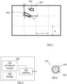
- Figure 1 shows a schematic top view of a vehicle 100 equipped with a vehicle sensor system 140.
- the vehicle moves in a direction with velocity vector v ego .
- the vehicle sensor system 140 comprises a vehicle sensor 110 and a control unit arrangement 120.
- the control unit arrangement 120 is arranged to control operation of the vehicle sensor 110, and to obtain data from the vehicle sensor, such as detections or data points corresponding to objects 150, 160 in the vicinity of the vehicle 100.
- the vehicle sensor 110 is associated with a field of view 115, which may be a 360-degree field of view, or a more limited field of view as shown in Figure 1 .
- Two objects 150, 160 are located in the field of view 115.
- a first object 160 generates a data point marked by a star 161.
- a second object 150 generates a data point marked by a square 151.
- the vehicle sensor 110 may comprise a single sensor unit or a plurality of sensor units, potentially of different type and/or of different configuration.
- the vehicle sensor 110 is a radar sensor 110.
- the radar sensor 110 is arranged to generate a number of data points comprising coordinates in a relative coordinate system, i.e., relative to the location and orientation of the sensor.
- the data points may also comprise additional information, such as signal strength values, frequency values, and measures of signal-to-noise ratio (SNR).
- SNR signal-to-noise ratio
- One or more time-stamps may also be associated with the detections.
- the time stamps may be assigned per data point or be common to a set of data points.
- a data point in general, is a value or collection of values representing a configuration of an object or part of an object in an environment, such as in a vicinity of a vehicle.
- a data point may also comprise a velocity estimate obtained from a Doppler shift of a received waveform, and an angle or bearing obtained from an angle of arrival of a reflected sensor signal waveform.
- the velocity data may in some cases be quantized into moving or stationary, since some aspects of the methods disclosed herein comprises discarding data points related to stationary objects.
- a sensor data point is at times referred to as a detection. According to some aspects, these terms can be considered equivalent unless otherwise explicitly stated.
- New data points are produced more or less continuously by the sensor in cycles or scans.
- Most sensor systems generate detection data on a regular basis, with a cycle interval of T seconds.
- the interval T may correspond to a frame length of a radar signal, or to an image processing duration of a camera-based sensor, or to a scan period of a laser scanner. Detections may be stored and retrieved for processing as needed.
- Each detection here each radar detection 151, 161, comprises information of a measured range r, azimuth angle ⁇ , relative Doppler velocity v and magnitude m. Alternatively, the signal-to-noise ratio could be used similarly. Given the current ego speed v e and yaw rate ⁇ e provided by the ego vehicle 100, the detections 151, 161 can be classified into ground stationary versus moving detections, using well known standard methods. Only moving detections will be considered in the following.
- the present disclosure relates to a computer-implemented method for providing a machine learning model, where the machine learning model is adapted to provide predictions regarding position and over-ground velocity vectors v g1 , v g2 for detected multiple moving objects 150, 160 in a traffic environment using vehicle sensor data.
- the method comprises obtaining S100 detections 151, 161 related to the objects 150, 160 and representing S200 the detections 151, 161 by means of Cartesian detection coordinates and a transformed Doppler velocity ⁇ , having a ground frame of reference, in a detection list.
- ⁇ is the Doppler velocity that would have been measured at that position if the ego vehicle 100 had been stationary. Therefore, these transformed values can be used to infer the over ground velocity vector of an object in the same way in which the relative velocity vector could be inferred from v .
- the method further comprises discretizing S300 the detection list into an occupancy pixel grid in the form of a 3D array g ⁇ R n x ⁇ n y ⁇ n c where a first dimension n x and a second dimension n y correspond to the Cartesian coordinates for the detections 151, 161 and a third dimension n c comprises at least two channels, a first channel representing the detection magnitude, and a second channel representing the transformed Doppler velocity ⁇ .
- the pixels in the grid do not need to correspond to single detection, it is possible that multiple detections are aggregated into one pixel.
- n c 2 channels, one for the detection magnitude, and one for the Doppler velocity.
- the physical boundaries are specified, as well as the number of pixels ( n x , n y ) defining the resolution ( ⁇ x , ⁇ y ).
- the method also comprises training S400 an object detection model in a neural network using the 3D array g and corresponding ground truth labels for the objects 150, 160, where the ground truth labels comprise true values for position, extent, over-ground velocity vector and object class for all data samples.
- the object detection model is based on YOLO, You Only Look Once, using the three dimensions n x ⁇ n y ⁇ n c .
- the term sample refers one full input grid which is fed to the NN, and which is constructed from all radar detections in one radar measurement cycle.
- radar data is transformed from a point-cloud to a pixel grid where the x-y-dimensions correspond to a birds-eye-view, not to a depth-projection as in camera images.
- the 2 channels mentioned contain the signal strength, and the radial Doppler velocity of the radar measurements, respectively.
- the NN is enabled to predict an over-ground velocity vector of the objects. This is enabled by including the Doppler velocity, by transforming the measured Doppler to the ground-stationary frame of reference and combining this with the full spatial 2D information.
- the machine learning model is adapted to provide predictions also regarding at least one of extent and object class.
- the method comprises normalizing the detection magnitudes and transformed Doppler values by specifying an expected or measured maximum value m max and v max , respectively.
- the method comprises forming N x ⁇ N y rectangular cells 200 where N x is the number of rectangular cells 200 along an x-axis and N y is the number of rectangular cells 200 along a y-axis, each rectangular cell 200 having a length 1 and a width w.
- the x-range and y-range are split equidistantly.
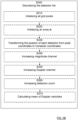
- Figure 2 is thus a depiction of example outputs, predictions P, of the NN, and how they would be rendered in the birds-eye-view.
- the cells there are boxes that represent objects, in the example there are two boxes 250, 260 in one cell 200.
- the number N par of parameters specifying one object prediction P equals 7+ N c , where N c denotes the number of object classes, where the parameters specifying each object prediction P comprise:
- FIG. 2 An example visualization of the predictions for one of the grid cells 200 is shown in Figure 2 .
- the minimum and maximum values 0,1 correspond to the boundaries of the grid cell 200.
- the probability prediction p can be used to obtain a variable number of actual predicted objects: only objects with p > p 0 will at prediction time considered as predictions, whereas objects with p ⁇ p 0 are non-predictions.
- the optimal threshold p 0 can for example be obtained by an ROC (Receiver Operating Characteristic) optimization after training the NN.
- the method comprises providing ground truth as labeled boxes consisting of true values for all the parameters corresponding to the predictions ( P 2 , ..., P 7 ), as well as the true object class ( P 8 , ..., P 7+ N c ), for all data samples.
- the present method can be applied to any NN architecture that takes input of the form g and outputs a prediction vector P ⁇ [0, 1] N .
- a typical architecture might consist of several convolutional layers, followed by max-pooling layers, and some fully connected layers at the end, followed by a sigmoid activation for ( P 1 , ..., P 7 ) and a soft-max activation for the class probabilities c i .
- Table 1 below shows an example of a NN architecture. This is to be regarded as an illustrative example of a possible NN architecture, many other types of NN architectures are of course possible in view of the present disclosure.
- Table 1 Example of NN architecture Type Size/Stride Output Channels Input 256 ⁇ 128 2 Convolution 3 ⁇ 3 256 ⁇ 128 8 Max Pool 2 ⁇ 2 / 2 128 ⁇ 64 Convolution 3 ⁇ 3 128 ⁇ 64 16 Max Pool 2 ⁇ 2 / 2 64 ⁇ 32 Convolution 3 ⁇ 3 64 ⁇ 32 32 Convolution 1 ⁇ 1 64 ⁇ 32 16 x 1 Convolution 3 ⁇ 3 64 ⁇ 32 32 Max Pool 2 ⁇ 2 / 2 32 ⁇ 16 Convolution 3 ⁇ 3 32 ⁇ 16 32 Convolution 1 ⁇ 1 32 ⁇ 16 16 x 1 Convolution 3 ⁇ 3 32 ⁇ 16 32 Max Pool 2 ⁇ 2 / 2 16 ⁇ 8 Convolution 3 ⁇ 3 16 ⁇ 8 Convolution 1 ⁇ 1 16 ⁇ 8 32 x
- n x , n y , n c (256,128,2)
- N x , N y ) (4,3) grid cells
- N c 3 object classes
- N obj 6 predicted objects per cell, that could be used.
- Each convolutional layer is understood to be followed by a batch-normalization layer, and all convolutional and fully connected layers are followed by an activation function, for example a ReLU.
- Some aspects of the present disclosure correspond to traditional YOLO, like dividing the output space into grid cells, predicting bounding boxes with existence probabilities, locations, sizes and object classes, and the inspiration for the given example NN architecture.
- the radar data are transformed from a point-cloud to a pixel gird.
- the pixel grid has the same dimension as in YOLO, their meanings are different: the x-y-dimensions correspond to the birds-eye-view, not to a depth-projection as in camera images, and the 2 channels contain the signal strength, and the radial Doppler velocity of the radar measurements, respectively.
- the NN also predicts the over-ground velocity vector, equivalently, the speed and orientation, of the objects. This is enabled by including the Doppler velocity and by transforming the measured Doppler velocity to the ground-stationary frame of reference, and by combining this with the full spatial 2D information.
- the loss function is adapted to these additional predictions.
- the present disclosure also relates to a computer-implemented method for detecting multiple moving objects 150, 160.
- the method comprises using T100 the trained machine learning model being trained in accordance with the computer-implemented method as described herein, and/or being trained in accordance with the computer-implemented method as described herein, and using (T200) one or more radar sensors for collecting data.
- the computer-implemented method further comprises implementing T300 the machine learning model by, for each input 3D array g , outputting object predictions P for each detected object 150, 160.
- each object prediction P comprises:
- the training of the NN is performed offline using a remote server, using a large dataset that has been collected and labelled before. Once the NN has been trained, it can be deployed on whatever computing hardware that is used in the vehicle 100, such as the control unit arrangement 120. It would then run on the vehicle 100 and assist analysis of detect objects 150, 160, without further changing its learned parameters.
- the computer-implemented method may be adapted to at least partly run on, and via, external units, for example a communication system 190 that provides wireless communication 191.
- a communication system 190 that provides wireless communication 191.
- This may, e.g., be a third generation partnership program (3GPP) defined access network like the fourth generation (4G) or the fifth generation (5G) access networks or a satellite system such as GPS.
- the access network may provide access to remote networks and other resources such as, e.g., the Internet.
- processing functions may be performed by resources in a remote network 192, such as the remote server 193.
- the control unit arrangement 120 may be constituted by a control unit arrangement with one or more control unit parts that can be separate from each other. Some or all control unit parts may be comprised in a control unit arrangement 120 and/or the remote server 193.
- the present disclosure relates to a control unit arrangement 120, 19) adapted to control at least one of the computer-implemented method for providing a machine learning model as described herein, and the computer-implemented method for detecting multiple moving objects 150, 160 as described herein.
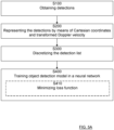
- Figure 3 schematically illustrates, in terms of a number of functional units, the components of the control unit arrangement 120 according to an embodiment.
- Processing circuitry 710 is provided using any combination of one or more of a suitable central processing unit (CPU), multiprocessor, microcontroller, digital signal processor (DSP), dedicated hardware accelerator, etc., capable of executing software instructions stored in a computer program product, e.g. in the form of a storage medium 730.
- the processing circuitry 710 may further be provided as at least one application specific integrated circuit (ASIC), or field programmable gate array (FPGA) .
- ASIC application specific integrated circuit
- FPGA field programmable gate array
- the processing circuitry 710 is configured to cause the control unit arrangement 120 to perform a set of operations, or steps. These operations, or steps, were discussed above in connection to the various methods described.
- the storage medium 730 may store the set of operations
- the processing circuitry 710 may be configured to retrieve the set of operations from the storage medium 730 to cause the control unit arrangement 120 to perform the set of operations.
- the set of operations may be provided as a set of executable instructions.
- the processing circuitry 710 is thereby arranged to execute methods and operations as herein disclosed.
- the storage medium 730 may also comprise persistent storage, which, for example, can be any single one or combination of magnetic memory, optical memory, solid state memory or even remotely mounted memory.
- the control unit arrangement 120 may further comprise a communications interface 720 for communications with at least one other unit such as the radar sensor 110.
- the communications interface 720 may comprise one or more transmitters and receivers, comprising analogue and digital components and a suitable number of ports for wired or wireless communication.
- the processing circuitry 710 is adapted to control the general operation of the control unit arrangement 120 e.g. by sending data and control signals to the external unit and the storage medium 730, by receiving data and reports from the external unit, and by retrieving data and instructions from the storage medium 730.
- Other components, as well as the related functionality, of the control unit arrangement 120 are omitted in order not to obscure the concepts presented herein.
- Figure 4 shows a computer program product 810 comprising computer executable instructions 820 arranged on a computer readable medium 830 to execute any of the methods disclosed herein.
- the present disclosure relates to a computer program 810 comprising computer program code which, when executed in a control unit arrangement 120, 193, causes the control unit arrangement 120, 193 to execute the method for providing a machine learning model as described herein.
- the present disclosure also relates to a computer program 810 comprising computer program code which, when executed in a control unit arrangement 120, 193, causes the control unit arrangement 120, 193 to execute the method for detecting multiple moving objects 150, 160 as described herein.
- a computer program can be constitued by a computer program product.
- the present disclosure relates to a Deep Learning method to detect and classify moving objects 150, 160 with a radar sensor 110.
- First the detection list measured by the sensor is discretize into an occupancy grid, and then labeled data are used to train a deep neural network (NN) with an appropriate loss function, to predict for example the existence probability, location, extent, velocity vector, and object class such as for example pedestrian, car, etc. of each moving object.
- NN deep neural network
- the radar sensor 110 also provides data regarding Doppler velocities which are here included as part of the input grids, it is possible predict the velocity vectors for the objects.
- the method can be applied to any NN architecture that takes input of the form g and outputs a prediction vector P ⁇ [0, 1] N .
- the discretization of detections into the occupancy grid can be modified by using at least one of “smeared discretization”, “additional channels”, “elevation”, “add stationary detections” and “raw radar input data.
- smeared discretization relates to instead of incrementing the values of one pixel in the magnitude channel for one detection, a smeared distribution (e.g. a Gaussian with specified widths in range and azimuth) is used to increase the values of some of the neighboring pixels, such that the total sum of the increment is equal to the detection magnitude.
- a smeared distribution e.g. a Gaussian with specified widths in range and azimuth
- Using additional channels relates to that in addition to the magnitude and mean-Doppler channel, a channel is added with the standard deviation, or maximum absolute difference, of the transformed and normalized Doppler velocity. Furthermore, instead of using the mean of the Doppler velocity, the median can be used. This can be helpful to reduce the negative impact of micro-Dopplers on the group velocity estimate. If the Doppler spread instead is used in a separate channel as described before, the micro-Doppler information is still available, and can turn into a useful classification feature. Moreover, additional channels can be added for further detection properties which are provided by the RSP, e.g. the noise threshold, or some quality bits.
- elevation relates to that if the RSP also provides the elevation angle for each detection, this can be added as an additional input channel, similar to the Doppler channel, or as an additional dimension of the pixel grid.
- Using added stationary detections relates to that it is not necessary to exclude ground-stationary detections from the pixel grid. In general, they can be included as well, potentially accompanied by an additional binary channel containing the "is stationary" information. This could help the NN learn some contextuality, e.g. that certain object predictions are more or less likely, given the neighboring stationary environment.
- raw radar input data relates to that instead of first performing conventional RSP to obtain detections, and then turning the detection list into a pixel grid, it is possible to directly work with the raw radar input data in the form of range-Doppler maps for each virtual antenna channel, or range-Doppler-azimuth(-elevation) maps.
- the specific NN architecture shown is only one example. Many different architectures can be used, for example with skip connections, or a fully convolutional architecture.
- a first step could according to some aspects be to add a conventional filtering step, e.g. a Kalman filter, for post-processing the NN predictions.
- a conventional filtering step e.g. a Kalman filter
- An alternative approach is to directly use a recurrent neural network (RNN) for keeping memory about previously detected objects.
- RNN recurrent neural network
- the NN can be trained not only on real object classes, but also for distinguishing real vs. ghost objects. This can be achieved by adding a corresponding binary class "is ghost" to the predicted object parameters, and adding ghost objects to the training data. If all real objects within the data were already labeled, no additional labeling of ghost objects would be needed.
- the NN would learn to classify ghost objects, given that pixels from the whole input grid can influence the outcome of a particular predicted object, and so the NN can learn to use not only the detections from the given object, but also the context present in the whole scene.
- anchor boxes For training of the NN, according to some aspects, so-called anchor boxes can be used, where the anchor boxes are based not only on the predicted positions, but also on the velocities. Furthermore, for associating true and predicted objects during training, according to some aspects, more complex metrics than the simple Euclidean distance metric can be used. For instance, the length and width, as well as the velocity vectors could be included into this metric. Again, this could help the NN to learn faster.
Landscapes
- Engineering & Computer Science (AREA)
- Radar, Positioning & Navigation (AREA)
- Remote Sensing (AREA)
- Physics & Mathematics (AREA)
- General Physics & Mathematics (AREA)
- Computer Networks & Wireless Communication (AREA)
- Theoretical Computer Science (AREA)
- Evolutionary Computation (AREA)
- Computer Vision & Pattern Recognition (AREA)
- Artificial Intelligence (AREA)
- Multimedia (AREA)
- Electromagnetism (AREA)
- Databases & Information Systems (AREA)
- General Health & Medical Sciences (AREA)
- Medical Informatics (AREA)
- Software Systems (AREA)
- Computing Systems (AREA)
- Health & Medical Sciences (AREA)
- Radar Systems Or Details Thereof (AREA)
Abstract
The present disclosure relates to a computer-implemented method for providing a machine learning model, where the machine learning model is adapted to provide predictions regarding position and over-ground velocity vectors for detected multiple moving objects (150, 160) in a traffic environment using vehicle sensor data. The method comprises, for each radar measurement cycle in a plurality of radar measurement cycles for detecting the objects (150, 160);obtaining (S100) detections (151, 161) related to the objects (150, 160);representing (S200) the detections (151, 161) by means of Cartesian detection coordinates and a transformed Doppler velocity (ṽ), having a ground frame of reference, in a detection list; anddiscretizing (S300) the detection list into an occupancy pixel grid in the form of a 3D array g∈ℝnx×ny×nc.A first dimension n<sub>x</sub> and a second dimension n<sub>y</sub> correspond to the Cartesian coordinates for the detections (151, 161) and a third dimension n<sub>c</sub> comprises at least two channels, a first channel representing the detection magnitude, and a second channel representing the transformed Doppler velocity (ṽ).The method further comprisestraining (S400) an object detection model in a neural network using the 3D array g and corresponding ground truth labels for the objects (150, 160), where the ground truth labels comprise true values for position, extent, over-ground velocity vector and object class for all data samples,where the object detection model is based on YOLO, You Only Look Once, using the three dimensions n<sub>x</sub> × n<sub>y</sub> × n<sub>c</sub>.
Description
- The present disclosure relates to methods, sensor system control units, and vehicles for implementing Deep Learning methods to detect and classify objects, based on the method YOLO, You Only Look Once, where the objects have been detected by means of vehicle sensors.
- Vehicle environment detection systems, such as for example camera systems, radio detection and ranging (radar) systems and light detection and ranging (lidar) systems, can be mounted on a vehicle in order to detect objects in a vicinity of the vehicle. The obtained detections can be used to implement functions such as speed control and collision prevention, ego motion estimation and scene understanding.
- There exist Deep Learning methods to detect and classify moving objects, for example using the method YOLO, You Only Look Once, that for example is described in J. Redmon, S. Divvala, R. Girshick and A. Farhadi, "You Only Look Once: Unified, Real-Time Object Detection," arXiv, 2015, initially being intended for classifying objects in vision data.
- YOLO has also been implemented for radar sensors, as for example described in Rodrigo Perez, Falk Schubert, Ralph Rasshofer and Erwin Biebl, "Deep Learning Radar Object Detection and Classification for Urban Automotive Scenarios", 2019 Kleinheubach Conference, and Biesbroeck, J.P.A. "Neural network based multiple object tracking for automotive FMCW radar data", Eindhoven University of Technology 2018.
- However, there is still a need to improve Deep Learning methods for detecting and classifying objects that have been detected by means of vehicle radar sensors based on YOLO.
- It is an object of the present disclosure to provide improved Deep Learning methods for detecting and classifying objects that have been detected by means of vehicle radar sensors based on YOLO.
- This object is obtained at least in part by a method computer-implemented method for providing a machine learning model. The machine learning model is adapted to provide predictions regarding position and over-ground velocity vectors for detected multiple moving objects in a traffic environment using vehicle sensor data. The method comprises, for each radar measurement cycle in a plurality of radar measurement cycles for detecting the objects, obtaining detections related to the objects, representing the detections by means of Cartesian detection coordinates and a transformed Doppler velocity, having a ground frame of reference, in a detection list, and discretizing the detection list into an occupancy pixel grid in the form of a 3D array

- A first dimension nx and a second dimension ny correspond to the Cartesian coordinates for the detections, and a third dimension nc comprises at least two channels, a first channel representing the detection magnitude, and a second channel representing the transformed Doppler velocity.
- The method further comprises training an object detection model in a neural network using the 3D array g and corresponding ground truth labels for the objects, where the ground truth labels comprise true values for position, extent, over-ground velocity vector and object class for all data samples. The object detection model is based on YOLO, You Only Look Once, using the three dimensions nx × ny × nc.
- In this way, radar data is transformed from a point-cloud to a pixel grid where the x-y-dimensions correspond to a birds-eye-view, not to a depth-projection as in camera images. The 2 channels mentioned contain the signal strength, and the radial Doppler velocity of the radar measurements, respectively.
- The NN is enabled to predict an over-ground velocity vector of the objects. This is enabled by including the Doppler velocity, by transforming the measured Doppler to the ground-stationary frame of reference and combining this with the full spatial 2D information.
- According to some aspects, the machine learning model is adapted to provide predictions regarding at least one of extent and object class.
- According to some aspects, the method comprises normalizing the detection magnitudes and transformed Doppler values by specifying an expected or measured maximum value mmax and vmax, respectively.
- This means that the input values for the NN are of
order 1. - According to some aspects, for each radar measurement cycle, the discretizing comprises initializing all grid pixels with zeros such that the 3D array g = 0, and initializing an array


- This provides an efficient discretizing.
- According to some aspects, the method comprises forming Nx×Ny rectangular cells where Nx is the number of rectangular cells along an x-axis and Ny is the number of rectangular cells along a y-axis, each rectangular cell having a
length 1 and a width w, such that the output of the neural network for one input 3D array g then consists of a total of N = Nx · Ny · Nobj · Npar neurons with values in the range [0,1], where Npar is the number of parameters specifying one object prediction P and Nobj is the fixed maximum number of objects each cell is capable of predicting. According to some aspects, the number Npar of parameters specifying one object prediction P equals 7+Nc, where Nc denotes the number of object classes, where the parameters specifying each object prediction P comprise: - existence probability P 1 = p
- box center position (P 2 , P 3) = (x̂, ŷ)
- box length, width (P 4, P 5) = (l̂, ŵ)
- velocity (over ground) (P 6, P 7) = (v̂x , v̂y )
- class probabilities (P 8, ..., P 7+Nc ) = ck (k = 1...Nc )
- According to some aspects, the method comprises providing ground truth as labeled boxes consisting of true values for all the parameters corresponding to the predictions (P 2, ..., P 7), as well as the true object class (P 8, ..., P 7+Nc ), for all data samples. Before training, the method comprises assigning truth objects to the corresponding grid cells, depending on which cell the box center lies in, re-scaling the physical parameter values to the normalized ones with range [0,1] in the same way as the predictions are rescaled, and forming a full truth vector for one object in the form:

- Capital letters distinguish the components of the truth from the predictions P.
- According to some aspects, the training comprises minimizing a loss function according to

- true objects:

- no true objects:

- box position & size:


- velocity vector:

- object class :

- The sums over i = 1 ... (Nx · Ny · Nobj ) are over all objects in all grid cells, and k = 1 ... Nc over the object classes, and where the symbol
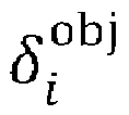

- This means that training according to the present disclosure can be based on well-known loss functions. In principle, the present method can be applied to any NN architecture that takes input of the form g and outputs a prediction vector P ∈ [0, 1] N .
- According to some aspects, the third dimension nc comprises a third channel with the standard deviation, or maximum absolute difference, of the transformed and normalized Doppler velocity.
- This means that the negative impact of micro-Doppler on the group velocity estimate can be reduced. Also, consequently, the third dimension nc may comprise any sutaible channels.
- This object is also achieved by means of further methods, control unit arrangements and computer programs that are associated with the above advantages.
- The present disclosure will now be described in detail with reference to the appended drawings, where:
- Figure 1
- shows a schematic top view of a vehicle with a sensor system;
- Figure 2
- shows a plurality of rectangular cells;
- Figure 3
- schematically illustrates a control unit;
- Figure 4
- shows an example computer program product;
- Figure 5A
- is a flow chart illustrating methods;
- Figure 5B
- is a flow chart illustrating methods within method step S300 of
Figure 5A ; and - Figure 6
- is a flow chart illustrating further methods.
- Aspects of the present disclosure will now be described more fully hereinafter with reference to the accompanying drawings. The different devices, systems, computer programs and methods disclosed herein can, however, be realized in many different forms and should not be construed as being limited to the aspects set forth herein. Like numbers in the drawings refer to like elements throughout.
- The terminology used herein is for describing aspects of the disclosure only and is not intended to limit the invention. As used herein, the singular forms "a", "an" and "the" are intended to include the plural forms as well, unless the context clearly indicates otherwise.
-
Figure 1 shows a schematic top view of avehicle 100 equipped with avehicle sensor system 140. The vehicle moves in a direction with velocity vector vego. Thevehicle sensor system 140 comprises avehicle sensor 110 and acontrol unit arrangement 120. - The
control unit arrangement 120 is arranged to control operation of thevehicle sensor 110, and to obtain data from the vehicle sensor, such as detections or data points corresponding toobjects vehicle 100. - The
vehicle sensor 110 is associated with a field ofview 115, which may be a 360-degree field of view, or a more limited field of view as shown inFigure 1 . Twoobjects view 115. Afirst object 160 generates a data point marked by astar 161. Asecond object 150 generates a data point marked by a square 151. - The
vehicle sensor 110 may comprise a single sensor unit or a plurality of sensor units, potentially of different type and/or of different configuration. Here, thevehicle sensor 110 is aradar sensor 110. - The
radar sensor 110 is arranged to generate a number of data points comprising coordinates in a relative coordinate system, i.e., relative to the location and orientation of the sensor. - The data points may also comprise additional information, such as signal strength values, frequency values, and measures of signal-to-noise ratio (SNR).
- One or more time-stamps may also be associated with the detections. The time stamps may be assigned per data point or be common to a set of data points.
- A data point, in general, is a value or collection of values representing a configuration of an object or part of an object in an environment, such as in a vicinity of a vehicle. A data point may also comprise a velocity estimate obtained from a Doppler shift of a received waveform, and an angle or bearing obtained from an angle of arrival of a reflected sensor signal waveform. The velocity data may in some cases be quantized into moving or stationary, since some aspects of the methods disclosed herein comprises discarding data points related to stationary objects.
- A sensor data point is at times referred to as a detection. According to some aspects, these terms can be considered equivalent unless otherwise explicitly stated.
- New data points are produced more or less continuously by the sensor in cycles or scans. Most sensor systems generate detection data on a regular basis, with a cycle interval of T seconds. For instance, the interval T may correspond to a frame length of a radar signal, or to an image processing duration of a camera-based sensor, or to a scan period of a laser scanner. Detections may be stored and retrieved for processing as needed.
- Each detection, here each
radar detection ego vehicle 100, thedetections Figure 5 , the present disclosure relates to a computer-implemented method for providing a machine learning model, where the machine learning model is adapted to provide predictions regarding position and over-ground velocity vectors vg1, vg2 for detected multiple movingobjects objects S100 detections objects detections - This means that in order for a neural network (NN) to be able to predict over-ground velocity vectors of the objects, without having to input the ego speed v e and yaw rate ω e as auxiliary scalar inputs, and having the NN to learn the corresponding transformations as well, the Doppler velocities v of the detections are transformed to the ground frame of reference, according to some aspects via


- In other words, ṽ is the Doppler velocity that would have been measured at that position if the
ego vehicle 100 had been stationary. Therefore, these transformed values can be used to infer the over ground velocity vector of an object in the same way in which the relative velocity vector could be inferred from v. - If there are multiple detections within one spatial pixel, their magnitudes are added, while for the Doppler channel the mean is taken.
- The method further comprises discretizing S300 the detection list into an occupancy pixel grid in the form of a 3D array g ∈

detections - There are at least nc = 2 channels, one for the detection magnitude, and one for the Doppler velocity. For the two spatial dimensions, the physical boundaries are specified, as well as the number of pixels (nx, ny ) defining the resolution (Δx,Δy). As an example illustrating the above, for a forward looking
radar sensor 110, with x pointing in the forward direction, the following is chosen:

- This yields a spatial pixel resolution of 20×20cm. Together with the two channels, the full grid size would then be 500× 250x2. The specific parameter values to be used depend on the specifications of the radar sensor, as well as on the desired accuracy of the method.
- The method also comprises training S400 an object detection model in a neural network using the 3D array g and corresponding ground truth labels for the
objects - According to some aspects, the term sample refers one full input grid which is fed to the NN, and which is constructed from all radar detections in one radar measurement cycle.
- In this way, radar data is transformed from a point-cloud to a pixel grid where the x-y-dimensions correspond to a birds-eye-view, not to a depth-projection as in camera images. The 2 channels mentioned contain the signal strength, and the radial Doppler velocity of the radar measurements, respectively.
- The NN is enabled to predict an over-ground velocity vector of the objects. This is enabled by including the Doppler velocity, by transforming the measured Doppler to the ground-stationary frame of reference and combining this with the full spatial 2D information.
- According to some aspects, the machine learning model is adapted to provide predictions also regarding at least one of extent and object class.
- According to some aspects, the method comprises normalizing the detection magnitudes and transformed Doppler values by specifying an expected or measured maximum value mmax and vmax, respectively.
- This means that the input values for the NN are of
order 1. - According to some aspects, for each radar measurement cycle, the discretizing S300 comprises initializing S310 all grid pixels with zeros such that the 3D array g = 0, initializing S320 an array

radar detection 

- The discretizing S300 also comprises increasing S340 the magnitude channel of this pixel by the detection magnitude


calculating S370 the mean of their transformed Doppler velocities:
- This provides an efficient discretizing.
- According to some aspects, with reference to
Figure 2 , the method comprises forming Nx×Nyrectangular cells 200 where Nx is the number ofrectangular cells 200 along an x-axis and Ny is the number ofrectangular cells 200 along a y-axis, eachrectangular cell 200 having alength 1 and a width w. According to some aspects, the x-range and y-range are split equidistantly. - The output of the neural network for one input 3D array g then consists of a total of N = Nx · Ny · Nobj · Npar neurons, in this example with values in the range [0,1], where Npar is the number of parameters specifying one object prediction P and Nobj is the fixed maximum number of objects each cell is capable of predicting.
-
Figure 2 is thus a depiction of example outputs, predictions P, of the NN, and how they would be rendered in the birds-eye-view. In the cells there are boxes that represent objects, in the example there are twoboxes cell 200.Figure 2 thus shows example predictions in onegrid cell 200 for Nx = 4, Ny = 3, Nobj = 2. All other cells also have 2 predictors, which are not shown here. - According to some aspects, the number Npar of parameters specifying one object prediction P equals 7+Nc, where Nc denotes the number of object classes, where the parameters specifying each object prediction P comprise:
- existence probability P 1 = p
- box center position (P 2, P 3) = (x̂, ŷ)
- box length, width (P 4, P 5) = (l̂, ŵ)
- velocity over ground (P 6, P 7) = (v̂x , v̂y )
- class probabilities (P 8, ..., P 7+Nc ) = ck (k = 1...Nc )
- An example visualization of the predictions for one of the
grid cells 200 is shown inFigure 2 . For (x̂,ŷ), the minimum andmaximum values grid cell 200. For l, w, vx, vy the maximum physical values can be specified before training the NN, e.g. lmax = 20 m, wmax = 5 m,
- It should be noted that the probability prediction p can be used to obtain a variable number of actual predicted objects: only objects with p > p 0 will at prediction time considered as predictions, whereas objects with p < p 0 are non-predictions. The optimal threshold p 0 can for example be obtained by an ROC (Receiver Operating Characteristic) optimization after training the NN.
- According to some aspects, the method comprises providing ground truth as labeled boxes consisting of true values for all the parameters corresponding to the predictions ( P 2, ..., P7 ), as well as the true object class (P 8, ...,P 7+Nc ), for all data samples.
- Here, P1 is not used, since only actual objects are labeled, and the true value T1 corresponding to the prediction P1 is always = 1. P1 is therefore omitted here, only variable parameters which have to be provided by the labels being listed. The constant T1=1 can be added for all labels, see equation (6) below.
- According to some aspects, before training S400, the method comprises assigning truth objects to the corresponding grid cells, depending on which cell the box center lies in, re-scaling the physical parameter values to the normalized ones with range [0,1] in the same way as the predictions are rescaled, and forming a full truth vector for one object in the form

- According to some aspects, the training S400 comprises
minimizing S410 a loss function according to
- true objects:

- no true objects:

- box position & size:

- velocity vector:

- object class:

- Their values depend on the assignment of truth objects to the responsible grid cells, as discussed above. In addition, if Nobj > 1, the true objects within one cell have to be associated with the corresponding predictors within that cell. In traditional YOLO, this can be done based on the largest intersection over union (IOU) between the true and predicted boxes. Here, according to some aspects, a metric is used that is also nonzero if the boxes do not overlap. For example, the Euclidean distance between the centers of the boxes can used as the association metric to be minimized.
- This means that training according to the present disclosure can be based on well-known loss functions.
- In principle, the present method can be applied to any NN architecture that takes input of the form g and outputs a prediction vector P ∈ [0, 1] N . But a typical architecture might consist of several convolutional layers, followed by max-pooling layers, and some fully connected layers at the end, followed by a sigmoid activation for (P 1, ..., P 7) and a soft-max activation for the class probabilities ci .
- Table 1 below shows an example of a NN architecture. This is to be regarded as an illustrative example of a possible NN architecture, many other types of NN architectures are of course possible in view of the present disclosure.
Table 1: Example of NN architecture Type Size/Stride Output Channels Input 256 × 128 2 Convolution 3 × 3 256 × 128 8 Max Pool 2 × 2 / 2 128 × 64 Convolution 3 × 3 128 × 64 16 Max Pool 2 × 2 / 2 64 × 32 Convolution 3 × 3 64 × 32 32 Convolution 1 × 1 64 × 32 16 x 1 Convolution 3 × 3 64 × 32 32 Max Pool 2 × 2 / 2 32 × 16 Convolution 3 × 3 32 × 16 32 Convolution 1 × 1 32 × 16 16 x 1 Convolution 3 × 3 32 × 16 32 Max Pool 2 × 2 / 2 16 × 8 Convolution 3 × 3 16 × 8 Convolution 1 × 1 16 × 8 32 x 2 Convolution 3 × 3 16 × 8 64 Max Pool 2 × 2 / 2 8 × 4 Convolution 3 × 3 8 × 4 128 Convolution 1 × 1 8 × 4 64 x 2 Convolution 3 × 3 8 × 4 128 Fully Connected 1 × 1 2048 Fully Connected 1 × 1 1024 Object List Output 10 × 6 12 - Here, in accordance with some aspects, there are 18 convolutional layers, for a grid resolution (nx, ny, nc ) = (256,128,2), (Nx, Ny ) = (4,3) grid cells, Nc = 3 object classes, and Nobj = 6 predicted objects per cell, that could be used. Each convolutional layer is understood to be followed by a batch-normalization layer, and all convolutional and fully connected layers are followed by an activation function, for example a ReLU.
- The size (10,6) of the object list output layer corresponds to the number of object parameters Npar = 7 + 3 and the number of objects per cell, whereas the number of output channels corresponds to the total number of grid cells Nx · Ny = 12.
- Some aspects of the present disclosure correspond to traditional YOLO, like dividing the output space into grid cells, predicting bounding boxes with existence probabilities, locations, sizes and object classes, and the inspiration for the given example NN architecture.
- Due to the different nature of the radar data traditional YOLO has to be implemented in new ways in accordance with the present disclose. For example, the radar data are transformed from a point-cloud to a pixel gird.
- Even though the pixel grid has the same dimension as in YOLO, their meanings are different: the x-y-dimensions correspond to the birds-eye-view, not to a depth-projection as in camera images, and the 2 channels contain the signal strength, and the radial Doppler velocity of the radar measurements, respectively.
- The NN also predicts the over-ground velocity vector, equivalently, the speed and orientation, of the objects. This is enabled by including the Doppler velocity and by transforming the measured Doppler velocity to the ground-stationary frame of reference, and by combining this with the full spatial 2D information.
- The loss function is adapted to these additional predictions.
- With reference to
Figure 6 , the present disclosure also relates to a computer-implemented method for detecting multiple movingobjects - The computer-implemented method further comprises implementing T300 the machine learning model by, for each input 3D array g , outputting object predictions P for each detected
object - According to some aspects, each object prediction P comprises:
- existence probability P 1 = p
- box center position (P 2, P 3) = (x̂, ŷ)
- box length, width (P 4, P 5) = (l̂, ŵ)
- velocity (over ground) (P 6, P 7) = (v̂x , v̂y )
- class probabilities (P 8, ..., P 7+Nc ) = ck (k = 1...Nc )
- According to some aspects, the training of the NN is performed offline using a remote server, using a large dataset that has been collected and labelled before. Once the NN has been trained, it can be deployed on whatever computing hardware that is used in the
vehicle 100, such as thecontrol unit arrangement 120. It would then run on thevehicle 100 and assist analysis of detectobjects - Alternatively, once the NN has been trained, it can at least partly be run on a
remote server 193. According to some aspects, with reference toFigure 1 , the computer-implemented method may be adapted to at least partly run on, and via, external units, for example acommunication system 190 that provideswireless communication 191. This may, e.g., be a third generation partnership program (3GPP) defined access network like the fourth generation (4G) or the fifth generation (5G) access networks or a satellite system such as GPS. The access network may provide access to remote networks and other resources such as, e.g., the Internet. - It is also appreciated that some processing functions may be performed by resources in a
remote network 192, such as theremote server 193. - The
control unit arrangement 120 may be constituted by a control unit arrangement with one or more control unit parts that can be separate from each other. Some or all control unit parts may be comprised in acontrol unit arrangement 120 and/or theremote server 193. - The present disclosure relates to a
control unit arrangement 120, 19) adapted to control at least one of the computer-implemented method for providing a machine learning model as described herein, and the computer-implemented method for detecting multiple movingobjects -
Figure 3 schematically illustrates, in terms of a number of functional units, the components of thecontrol unit arrangement 120 according to an embodiment. -
Processing circuitry 710 is provided using any combination of one or more of a suitable central processing unit (CPU), multiprocessor, microcontroller, digital signal processor (DSP), dedicated hardware accelerator, etc., capable of executing software instructions stored in a computer program product, e.g. in the form of astorage medium 730. Theprocessing circuitry 710 may further be provided as at least one application specific integrated circuit (ASIC), or field programmable gate array (FPGA) . - Particularly, the
processing circuitry 710 is configured to cause thecontrol unit arrangement 120 to perform a set of operations, or steps. These operations, or steps, were discussed above in connection to the various methods described. For example, thestorage medium 730 may store the set of operations, and theprocessing circuitry 710 may be configured to retrieve the set of operations from thestorage medium 730 to cause thecontrol unit arrangement 120 to perform the set of operations. The set of operations may be provided as a set of executable instructions. Thus, theprocessing circuitry 710 is thereby arranged to execute methods and operations as herein disclosed. - The
storage medium 730 may also comprise persistent storage, which, for example, can be any single one or combination of magnetic memory, optical memory, solid state memory or even remotely mounted memory. - The
control unit arrangement 120 may further comprise acommunications interface 720 for communications with at least one other unit such as theradar sensor 110. As such, thecommunications interface 720 may comprise one or more transmitters and receivers, comprising analogue and digital components and a suitable number of ports for wired or wireless communication. - The
processing circuitry 710 is adapted to control the general operation of thecontrol unit arrangement 120 e.g. by sending data and control signals to the external unit and thestorage medium 730, by receiving data and reports from the external unit, and by retrieving data and instructions from thestorage medium 730. Other components, as well as the related functionality, of thecontrol unit arrangement 120 are omitted in order not to obscure the concepts presented herein. -
Figure 4 shows acomputer program product 810 comprising computerexecutable instructions 820 arranged on a computerreadable medium 830 to execute any of the methods disclosed herein. - The present disclosure relates to a
computer program 810 comprising computer program code which, when executed in acontrol unit arrangement control unit arrangement - The present disclosure also relates to a
computer program 810 comprising computer program code which, when executed in acontrol unit arrangement control unit arrangement objects - In this context, a computer program can be constitued by a computer program product.
- According to some aspects, the present disclosure relates to a Deep Learning method to detect and classify moving
objects radar sensor 110. First the detection list measured by the sensor is discretize into an occupancy grid, and then labeled data are used to train a deep neural network (NN) with an appropriate loss function, to predict for example the existence probability, location, extent, velocity vector, and object class such as for example pedestrian, car, etc. of each moving object. Since theradar sensor 110 also provides data regarding Doppler velocities which are here included as part of the input grids, it is possible predict the velocity vectors for the objects. - The method can be applied to any NN architecture that takes input of the form g and outputs a prediction vector P ∈ [0, 1] N.
- The present disclosure is not limited to the above, but may vary freely within the scope of the appended claims. In the following a plurality of implementation examples are provided.
- According to some aspects, the discretization of detections into the occupancy grid, can be modified by using at least one of "smeared discretization", "additional channels", "elevation", "add stationary detections" and "raw radar input data.
- Using smeared discretization relates to instead of incrementing the values of one pixel in the magnitude channel for one detection, a smeared distribution (e.g. a Gaussian with specified widths in range and azimuth) is used to increase the values of some of the neighboring pixels, such that the total sum of the increment is equal to the detection magnitude.
- Using additional channels relates to that in addition to the magnitude and mean-Doppler channel, a channel is added with the standard deviation, or maximum absolute difference, of the transformed and normalized Doppler velocity. Furthermore, instead of using the mean of the Doppler velocity, the median can be used. This can be helpful to reduce the negative impact of micro-Dopplers on the group velocity estimate. If the Doppler spread instead is used in a separate channel as described before, the micro-Doppler information is still available, and can turn into a useful classification feature. Moreover, additional channels can be added for further detection properties which are provided by the RSP, e.g. the noise threshold, or some quality bits.
- Using elevation relates to that if the RSP also provides the elevation angle for each detection, this can be added as an additional input channel, similar to the Doppler channel, or as an additional dimension of the pixel grid.
- Using added stationary detections relates to that it is not necessary to exclude ground-stationary detections from the pixel grid. In general, they can be included as well, potentially accompanied by an additional binary channel containing the "is stationary" information. This could help the NN learn some contextuality, e.g. that certain object predictions are more or less likely, given the neighboring stationary environment.
- Using raw radar input data relates to that instead of first performing conventional RSP to obtain detections, and then turning the detection list into a pixel grid, it is possible to directly work with the raw radar input data in the form of range-Doppler maps for each virtual antenna channel, or range-Doppler-azimuth(-elevation) maps.
- It was mentioned that the x-range and y-range of the
grid cells 200 illustrated inFigure 2 were split equidistantly. This is only an example, of course a non-equidistant spacing can be chosen. For instance, it could be advantageous to have a finer resolution in the near range. - Regarding the neural net as exemplified above with reference to Table 1, the specific NN architecture shown is only one example. Many different architectures can be used, for example with skip connections, or a fully convolutional architecture.
- So far, the methods according to the present disclosure are adapted for prediction of objects in each radar measurement cycle independently. In order to obtain more smooth trajectories of the predictions, a first step could according to some aspects be to add a conventional filtering step, e.g. a Kalman filter, for post-processing the NN predictions. An alternative approach is to directly use a recurrent neural network (RNN) for keeping memory about previously detected objects.
- A typical problem with radar sensors is that they often produce false (or "ghost") objects, e.g. due to wrongly estimated azimuth angles, or radar effects like clutter or multipath. To overcome this, according to some aspects, the NN can be trained not only on real object classes, but also for distinguishing real vs. ghost objects. This can be achieved by adding a corresponding binary class "is ghost" to the predicted object parameters, and adding ghost objects to the training data. If all real objects within the data were already labeled, no additional labeling of ghost objects would be needed.
- It is conceivable that the NN would learn to classify ghost objects, given that pixels from the whole input grid can influence the outcome of a particular predicted object, and so the NN can learn to use not only the detections from the given object, but also the context present in the whole scene.
- For training of the NN, according to some aspects, so-called anchor boxes can be used, where the anchor boxes are based not only on the predicted positions, but also on the velocities. Furthermore, for associating true and predicted objects during training, according to some aspects, more complex metrics than the simple Euclidean distance metric can be used. For instance, the length and width, as well as the velocity vectors could be included into this metric. Again, this could help the NN to learn faster.


Claims (15)
- A computer-implemented method for providing a machine learning model, where the machine learning model is adapted to provide predictions regarding position and over-ground velocity vectors for detected multiple moving objects (150, 160) in a traffic environment using vehicle sensor data, the method comprising, for each radar measurement cycle in a plurality of radar measurement cycles for detecting the objects (150, 160);obtaining (S100) detections (151, 161) related to the objects (150, 160);representing (S200) the detections (151, 161) by means of Cartesian detection coordinates and a transformed Doppler velocity (ṽ), having a ground frame of reference, in a detection list;discretizing (S300) the detection list into an occupancy pixel grid in the form of a 3D array
 training (S400) an object detection model in a neural network using the 3D array g and corresponding ground truth labels for the objects (150, 160), where the ground truth labels comprise true values for position, extent, over-ground velocity vector and object class for all data samples,where the object detection model is based on YOLO, You Only Look Once, using the three dimensions nx × ny × nc.
 - The computer-implemented method according to claim 1, wherein the machine learning model is adapted to provide predictions regarding at least one of extent and object class.
- The computer-implemented method according to any one of the claims 1 or 2, wherein the method comprises normalizing the detection magnitudes and transformed Doppler values by specifying an expected or measured maximum value mmax and vmax, respectively.
- The computer-implemented method according to claim 3, wherein, for each radar measurement cycle, the discretizing (S300) comprisesinitializing (S310) all grid pixels with zeros such that the 3D array g = 0;initializing (S320) an array
 transforming (S330) its position from polar coordinates (r,ϕ) to Cartesian coordinates (x,y) = (r cos ϕ , r sin ϕ) and determining the corresponding pixel coordinates according to (i,j) ∈ [1, nx ] × [1, ny ], such that x ∈ [(i - 1)Δx, i Δx), y ∈ [(j - 1)Δy, j Δy), where Δx, Δy is the resolution,increasing (S340) the magnitude channel of this pixel by the detection magnitude
 increasing (S350) the Doppler channel of this pixel by the transformed Doppler velocity according to
 increasing (S360) the detection count of this pixel by one according to
 calculating (S370) the mean of their transformed Doppler velocities: g[i,j,2] / = d[i,j].
 - The computer-implemented method according to claim 4, wherein the method comprises forming Nx×Ny rectangular cells (200) where Nx is the number of rectangular cells (200) along an x-axis and Ny is the number of rectangular cells (200) along a y-axis, each rectangular cell (200) having a length (1) and a width (w), such that the output of the neural network for one input 3D array g then consists of a total of N = Nx · Ny · Nobj · Npar neurons with values in the range [0,1], where Npar is the number of parameters specifying one object prediction P and Nobj is the fixed maximum number of objects each cell is capable of predicting.
- The computer-implemented method according to claim 5, wherein the number Npar of parameters specifying one object prediction P equals 7+Nc, where Nc denotes the number of object classes, where the parameters specifying each object prediction P comprise:- existence probability P 1 = p- box center position (P 2, P 3) = (x̂, ŷ)- box length, width (P 4, P 5) = (l̂, ŵ)- velocity (over ground) (P 6, P 7) = (v̂x , v̂y )- class probabilities (P 8, ..., P 7+Nc ) = ck (k = 1...Nc )where the hats ^ over symbols indicate that these symbols are normalized variables.
- The computer-implemented method according to claim 6, wherein the method comprisesproviding ground truth as labeled boxes consisting of true values for all the parameters corresponding to the predictions (P 2, ..., P 7), as well as the true object class (P 8, ..., P 7+Nc ), for all data samples, where, before training (S400), the method comprisesassigning truth objects to the corresponding grid cells, depending on which cell the box center lies in,re-scaling the physical parameter values to the normalized ones with range [0,1] in the same way as the predictions are rescaled,forming a full truth vector for one object in the form:where capital letters distinguish the components of the truth from the predictions P.

- The computer-implemented method according to claim 7, wherein the training (S400) comprises
minimizing (S410) a loss function according to • true objects :
 • no true objects:
 • box position & size:
 • velocity vector:
 • object class :where the sums over i = 1 ... (Nx · Ny · Nobj ) are over all objects in all grid cells, and k = 1 ... Nc , over the object classes, and where the symbol


- The computer-implemented method according to any one of the previous claims, wherein the third dimension nc comprises a third channel with the standard deviation, or maximum absolute difference, of the transformed and normalized Doppler velocity.
- A computer-implemented method for detecting multiple moving objects (150, 160) comprisingusing (T100) the trained machine learning model being trained in accordance with the computer-implemented method according to any one of the claims 5-7, and/or being trained in accordance with a computer-implemented method according to any one of the claims 5-7;using (T200) one or more radar sensors for collecting data;wherein the computer-implemented method comprises
implementing (T300) the machine learning model by, for each input 3D array g , outputting object predictions P for each detected object (150, 160). - The computer-implemented method according to claim 10, wherein each object prediction P comprises:- existence probability P 1 = p- box center position (P 2, P 3) = (x̂, ŷ)- box length, width (P 4, P 5) = (l̂, ŵ)- velocity (over ground) (P 6, P 7) = (v̂x , v̂y )- class probabilities (P 8, ..., P 7+Nc ) = ck (k = 1...Nc )where the hats ^ over symbols indicate that these symbols are normalized variables.
- The computer-implemented methods according to any one of the claims 1-11, further comprising directly using a recurrent neural network, RNN, for keeping memory about previously detected objects.
- A control unit arrangement (120, 193) adapted to control at least one of the computer-implemented method for providing a machine learning model according to any one of the claims 1-9 and the computer-implemented method for detecting multiple moving objects (150, 160) according to any one of the claims 10 or 11.
- A computer program (810) comprising computer program code which, when executed in a control unit arrangement (120, 193), causes the control unit arrangement (120, 193) to execute the method for providing a machine learning model according to any one of the claims 1-9.
- A computer program (810) comprising computer program code which, when executed in a control unit arrangement (120, 193), causes the control unit arrangement (120, 193) to execute the method for detecting multiple moving objects (150, 160) according to any one of the claims 10 or 11.
Priority Applications (1)
| Application Number | Priority Date | Filing Date | Title |
|---|---|---|---|
| EP22205511.3A EP4365624A1 (en) | 2022-11-04 | 2022-11-04 | Detection and classification of moving objects in radar data using deep learning |
Applications Claiming Priority (1)
| Application Number | Priority Date | Filing Date | Title |
|---|---|---|---|
| EP22205511.3A EP4365624A1 (en) | 2022-11-04 | 2022-11-04 | Detection and classification of moving objects in radar data using deep learning |
Publications (1)
| Publication Number | Publication Date |
|---|---|
| EP4365624A1 true EP4365624A1 (en) | 2024-05-08 |
Family
ID=84245880
Family Applications (1)
| Application Number | Title | Priority Date | Filing Date |
|---|---|---|---|
| EP22205511.3A Withdrawn EP4365624A1 (en) | 2022-11-04 | 2022-11-04 | Detection and classification of moving objects in radar data using deep learning |
Country Status (1)
| Country | Link |
|---|---|
| EP (1) | EP4365624A1 (en) |
Cited By (2)
| Publication number | Priority date | Publication date | Assignee | Title |
|---|---|---|---|---|
| CN119991810A (en) * | 2025-02-18 | 2025-05-13 | 安徽大学 | Vehicle pose estimation method based on semantic feature point detection |
| CN121366359A (en) * | 2025-12-22 | 2026-01-20 | 成都工业学院 | Intelligent detection method for double-branch remote sensing target fused with privacy calculation |
Citations (1)
| Publication number | Priority date | Publication date | Assignee | Title |
|---|---|---|---|---|
| DE102018203591B3 (en) * | 2018-03-09 | 2019-07-04 | Conti Temic Microelectronic Gmbh | Method and system for classifying road users |
-
2022
- 2022-11-04 EP EP22205511.3A patent/EP4365624A1/en not_active Withdrawn
Patent Citations (1)
| Publication number | Priority date | Publication date | Assignee | Title |
|---|---|---|---|---|
| DE102018203591B3 (en) * | 2018-03-09 | 2019-07-04 | Conti Temic Microelectronic Gmbh | Method and system for classifying road users |
Non-Patent Citations (4)
| Title |
|---|
| AO ZHANG ET AL: "RADDet: Range-Azimuth-Doppler based Radar Object Detection for Dynamic Road Users", ARXIV.ORG, CORNELL UNIVERSITY LIBRARY, 201 OLIN LIBRARY CORNELL UNIVERSITY ITHACA, NY 14853, 2 May 2021 (2021-05-02), XP081956764 * |
| BOCHKOVSKIY ALEXEY ET AL: "Yolov4: Optimal speed and accuracy of object detection", 22 April 2020 (2020-04-22), pages 1 - 17, XP093032778, Retrieved from the Internet <URL:https://arxiv.org/pdf/2004.10934.pdf> [retrieved on 20230317], DOI: 10.48550/arXiv.2004.10934 * |
| SCHUMANN OLE ET AL: "Scene Understanding With Automotive Radar", IEEE TRANSACTIONS ON INTELLIGENT VEHICLES, IEEE, vol. 5, no. 2, 25 November 2019 (2019-11-25), pages 188 - 203, XP011790609, ISSN: 2379-8858, [retrieved on 20200522], DOI: 10.1109/TIV.2019.2955853 * |
| SHELHAMER EVAN ET AL: "Fully Convolutional Networks for Semantic Segmentation", IEEE TRANSACTIONS ON PATTERN ANALYSIS AND MACHINE INTELLIGENCE, vol. 39, no. 4, 1 April 2017 (2017-04-01), USA, pages 640 - 651, XP055865277, ISSN: 0162-8828, DOI: 10.1109/TPAMI.2016.2572683 * |
Cited By (2)
| Publication number | Priority date | Publication date | Assignee | Title |
|---|---|---|---|---|
| CN119991810A (en) * | 2025-02-18 | 2025-05-13 | 安徽大学 | Vehicle pose estimation method based on semantic feature point detection |
| CN121366359A (en) * | 2025-12-22 | 2026-01-20 | 成都工业学院 | Intelligent detection method for double-branch remote sensing target fused with privacy calculation |
Similar Documents
| Publication | Publication Date | Title |
|---|---|---|
| Jebamikyous et al. | Autonomous vehicles perception (avp) using deep learning: Modeling, assessment, and challenges | |
| CN113348422B (en) | Method and system for generating a predicted occupancy grid map | |
| EP4022342B1 (en) | Estimating in-plane velocity from a radar return of a stationary roadside object | |
| US12352597B2 (en) | Methods and systems for predicting properties of a plurality of objects in a vicinity of a vehicle | |
| JP7239703B2 (en) | Object classification using extraterritorial context | |
| KR102860331B1 (en) | Method and device to improve radar data using reference data | |
| Sless et al. | Road scene understanding by occupancy grid learning from sparse radar clusters using semantic segmentation | |
| EP3511863B1 (en) | Distributable representation learning for associating observations from multiple vehicles | |
| WO2021174770A1 (en) | Machine-learning based system for path and/or motion planning and method of training | |
| CN112230193A (en) | Radar data processing equipment and local stroke resolution adjustment method | |
| US10872228B1 (en) | Three-dimensional object detection | |
| US12162512B2 (en) | Systems and methods for onboard analysis of sensor data for sensor fusion | |
| US11281916B2 (en) | Method of tracking objects in a scene | |
| Magnier et al. | Automotive LIDAR objects detection and classification algorithm using the belief theory | |
| EP3639241A1 (en) | Voxel based ground plane estimation and object segmentation | |
| Faisal et al. | Object detection and distance measurement using AI | |
| GB2627455A (en) | A computer-implemented method for semantic segmentation of point cloud data and applications thereof | |
| US10268204B2 (en) | Cross traffic detection using cameras | |
| Sakic et al. | Camera-lidar object detection and distance estimation with application in collision avoidance system | |
| Lamane et al. | Classification of targets detected by mmWave radar using YOLOv5 | |
| US20240418860A1 (en) | METHOD AND SYSTEM FOR VALIDATING END-TO-END LiDAR SENSING AND DIGITAL SIGNAL PROCESSOR OPTIMIZATION FOR 3D OBJECT DETECTION AND DEPTH ESTIMATION | |
| Gálvez del Postigo Fernández | Grid-based multi-sensor fusion for on-road obstacle detection: Application to autonomous driving | |
| EP3588136B1 (en) | Object representation and classification based on vehicle sensor detections | |
| EP4632426A1 (en) | Extracting features from queued radar frames | |
| Su et al. | An asymmetric radar-camera fusion framework for autonomous driving |
Legal Events
| Date | Code | Title | Description |
|---|---|---|---|
| PUAI | Public reference made under article 153(3) epc to a published international application that has entered the european phase |
Free format text: ORIGINAL CODE: 0009012 |
|
| STAA | Information on the status of an ep patent application or granted ep patent |
Free format text: STATUS: THE APPLICATION HAS BEEN PUBLISHED |
|
| AK | Designated contracting states |
Kind code of ref document: A1 Designated state(s): AL AT BE BG CH CY CZ DE DK EE ES FI FR GB GR HR HU IE IS IT LI LT LU LV MC ME MK MT NL NO PL PT RO RS SE SI SK SM TR |
|
| RAP3 | Party data changed (applicant data changed or rights of an application transferred) |
Owner name: MAGNA ELECTRONICS SWEDEN AB |
|
| STAA | Information on the status of an ep patent application or granted ep patent |
Free format text: STATUS: THE APPLICATION IS DEEMED TO BE WITHDRAWN |
|
| 18D | Application deemed to be withdrawn |
Effective date: 20241109 |