EP4365514A1 - Pipeline device and refrigeration system having same - Google Patents
Pipeline device and refrigeration system having same Download PDFInfo
- Publication number
- EP4365514A1 EP4365514A1 EP23826523.5A EP23826523A EP4365514A1 EP 4365514 A1 EP4365514 A1 EP 4365514A1 EP 23826523 A EP23826523 A EP 23826523A EP 4365514 A1 EP4365514 A1 EP 4365514A1
- Authority
- EP
- European Patent Office
- Prior art keywords
- slit
- fitting plate
- slits
- length
- cavity
- Prior art date
- Legal status (The legal status is an assumption and is not a legal conclusion. Google has not performed a legal analysis and makes no representation as to the accuracy of the status listed.)
- Granted
Links
Images



Classifications
-
- F—MECHANICAL ENGINEERING; LIGHTING; HEATING; WEAPONS; BLASTING
- F24—HEATING; RANGES; VENTILATING
- F24F—AIR-CONDITIONING; AIR-HUMIDIFICATION; VENTILATION; USE OF AIR CURRENTS FOR SCREENING
- F24F1/00—Room units for air-conditioning, e.g. separate or self-contained units or units receiving primary air from a central station
- F24F1/06—Separate outdoor units, e.g. outdoor unit to be linked to a separate room comprising a compressor and a heat exchanger
- F24F1/26—Refrigerant piping
-
- F—MECHANICAL ENGINEERING; LIGHTING; HEATING; WEAPONS; BLASTING
- F24—HEATING; RANGES; VENTILATING
- F24F—AIR-CONDITIONING; AIR-HUMIDIFICATION; VENTILATION; USE OF AIR CURRENTS FOR SCREENING
- F24F1/00—Room units for air-conditioning, e.g. separate or self-contained units or units receiving primary air from a central station
- F24F1/06—Separate outdoor units, e.g. outdoor unit to be linked to a separate room comprising a compressor and a heat exchanger
- F24F1/26—Refrigerant piping
- F24F1/34—Protection means thereof, e.g. covers for refrigerant pipes
-
- B—PERFORMING OPERATIONS; TRANSPORTING
- B23—MACHINE TOOLS; METAL-WORKING NOT OTHERWISE PROVIDED FOR
- B23K—SOLDERING OR UNSOLDERING; WELDING; CLADDING OR PLATING BY SOLDERING OR WELDING; CUTTING BY APPLYING HEAT LOCALLY, e.g. FLAME CUTTING; WORKING BY LASER BEAM
- B23K1/00—Soldering, e.g. brazing, or unsoldering
- B23K1/0008—Soldering, e.g. brazing, or unsoldering specially adapted for particular articles or work
- B23K1/0012—Brazing of heat exchangers
-
- B—PERFORMING OPERATIONS; TRANSPORTING
- B23—MACHINE TOOLS; METAL-WORKING NOT OTHERWISE PROVIDED FOR
- B23K—SOLDERING OR UNSOLDERING; WELDING; CLADDING OR PLATING BY SOLDERING OR WELDING; CUTTING BY APPLYING HEAT LOCALLY, e.g. FLAME CUTTING; WORKING BY LASER BEAM
- B23K1/00—Soldering, e.g. brazing, or unsoldering
- B23K1/008—Soldering within a furnace
-
- F—MECHANICAL ENGINEERING; LIGHTING; HEATING; WEAPONS; BLASTING
- F25—REFRIGERATION OR COOLING; COMBINED HEATING AND REFRIGERATION SYSTEMS; HEAT PUMP SYSTEMS; MANUFACTURE OR STORAGE OF ICE; LIQUEFACTION SOLIDIFICATION OF GASES
- F25B—REFRIGERATION MACHINES, PLANTS OR SYSTEMS; COMBINED HEATING AND REFRIGERATION SYSTEMS; HEAT PUMP SYSTEMS
- F25B41/00—Fluid-circulation arrangements
- F25B41/40—Fluid line arrangements
-
- B—PERFORMING OPERATIONS; TRANSPORTING
- B23—MACHINE TOOLS; METAL-WORKING NOT OTHERWISE PROVIDED FOR
- B23K—SOLDERING OR UNSOLDERING; WELDING; CLADDING OR PLATING BY SOLDERING OR WELDING; CUTTING BY APPLYING HEAT LOCALLY, e.g. FLAME CUTTING; WORKING BY LASER BEAM
- B23K2101/00—Articles made by soldering, welding or cutting
- B23K2101/04—Tubular or hollow articles
- B23K2101/14—Heat exchangers
-
- B—PERFORMING OPERATIONS; TRANSPORTING
- B23—MACHINE TOOLS; METAL-WORKING NOT OTHERWISE PROVIDED FOR
- B23K—SOLDERING OR UNSOLDERING; WELDING; CLADDING OR PLATING BY SOLDERING OR WELDING; CUTTING BY APPLYING HEAT LOCALLY, e.g. FLAME CUTTING; WORKING BY LASER BEAM
- B23K2103/00—Materials to be soldered, welded or cut
- B23K2103/02—Iron or ferrous alloys
- B23K2103/04—Steel or steel alloys
-
- F—MECHANICAL ENGINEERING; LIGHTING; HEATING; WEAPONS; BLASTING
- F25—REFRIGERATION OR COOLING; COMBINED HEATING AND REFRIGERATION SYSTEMS; HEAT PUMP SYSTEMS; MANUFACTURE OR STORAGE OF ICE; LIQUEFACTION SOLIDIFICATION OF GASES
- F25B—REFRIGERATION MACHINES, PLANTS OR SYSTEMS; COMBINED HEATING AND REFRIGERATION SYSTEMS; HEAT PUMP SYSTEMS
- F25B2500/00—Problems to be solved
- F25B2500/22—Preventing, detecting or repairing leaks of refrigeration fluids
- F25B2500/222—Detecting refrigerant leaks
-
- F—MECHANICAL ENGINEERING; LIGHTING; HEATING; WEAPONS; BLASTING
- F25—REFRIGERATION OR COOLING; COMBINED HEATING AND REFRIGERATION SYSTEMS; HEAT PUMP SYSTEMS; MANUFACTURE OR STORAGE OF ICE; LIQUEFACTION SOLIDIFICATION OF GASES
- F25B—REFRIGERATION MACHINES, PLANTS OR SYSTEMS; COMBINED HEATING AND REFRIGERATION SYSTEMS; HEAT PUMP SYSTEMS
- F25B41/00—Fluid-circulation arrangements
Definitions
- the present disclosure relates to the technical field of refrigeration systems, and more particularly, to a pipeline device and a refrigeration system having same.
- a pipeline device in an air conditioner generally fixes an upper cover and a lower cover by welding, wherein the upper cover and the lower cover both have a plurality of cavity halves, and after fixing the upper cover and the lower cover, the cavity halves on the upper cover and the lower cover form a plurality of complete cavities, and these cavities are used for circulating a refrigerant.
- a solder is laid between the upper cover and the lower cover and is used for fixing the upper cover and the lower cover by welding.
- the present disclosure aims to solve, to some extent, at least one of the above-mentioned technical problems in the prior art. For this reason, the present disclosure provides a pipeline device for facilitating inleakage detection.
- the present disclosure also provides another pipeline device.
- the present disclosure also provides yet another pipeline device.
- the present disclosure also provides still yet another pipeline device.
- the present disclosure also provides a refrigeration system having a pipeline device as described above.
- the pipeline device includes: a first cover body and a second cover body, wherein the first cover body has a first fitting plate, the second cover body has a second fitting plate, wherein the first fitting plate and the second fitting plate face towards each other and fit with each other to form a first cavity and a second cavity for a refrigerant flow, and an isolation portion located between the first cavity and the second cavity, wherein an arrangement path of the isolation portion laterally faces towards an extension path of the first cavity and an extension path of the second cavity at two sides of the isolation portion; the isolation portion includes: at least one first slit and at least one second slit, at least one first slit provided on the first fitting plate and penetrating the first fitting plate; at least one second slit provided on the second fitting plate and penetrating the second fitting plate; wherein on a planar projection parallel to fitting surface of the first fitting plate and the second fitting plate, one of the at least one first slit is at least partially connected to at least one of the
- the pipeline device it is possible to accurately detect whether an inleakage has occurred between the first cavity and the second cavity by providing the isolation portion, thereby improving the safety in use of the pipeline device.
- the at least one first slit comprises a plurality of first slit, two adjacent first slit being spaced apart by a first spacing portion, the first spacing portion being aligned with one of the at least one second slit having a length not smaller than a length of the first spacing portion; and the at least one second slit comprises a plurality of second slit, two adjacent second slit being spaced apart by a second spacing portion, the second spacing portion being aligned with one of the at least one first slit having a length not smaller than a length of the second spacing portion.
- each of the at least one first slit is aligned with a part of one of the at least one second slit that is adjacent to the first slit, and is staggered with another part of the second slit.
- each of the at least one first slit is aligned with the one second slit adjacent to the first slit by a length not greater than 1/2 of a length of the first slit and not greater than 1/2 of a length of the second slit.
- each of the at least one first slit is aligned with the one second slit adjacent to the first slit by a length not smaller than 1/6 of the length of the first slit and not smaller than 1/6 of the length of the second slit.
- the at least one first slit comprises a plurality of first slit having equal lengths, distances between any two adjacent first slit being equal; and the at least one second slit comprises a plurality of second slit having equal lengths, distances between any two adjacent second slit being equal.
- the first fitting plate is fixed to the second fitting plate by welding or connected to the second fitting plate by using a fastener.
- the first cover body and the second cover body are made of stainless steel.
- the pipeline device includes: a first cover body comprising a first fitting plate, the first fitting plate having a plurality of first recesses hollowed in a first direction; a second cover body comprising a second fitting plate, the second fitting plate having a plurality of second recesses hollowed in a direction opposite to the first direction, wherein the second recesses have a one-to-one correspondence to the first recesses, wherein each of the second recesses and the corresponding first recess fit with each other to form a complete cavity, wherein an isolation portion is provided on the first fitting plate and the second fitting plate between two adjacent cavities, and wherein a length of the isolation portion is not shorter than a length of any one of the two adjacent cavities; and a solder layer provided between the first fitting plate and second fitting plate and used for soldering the first fitting plate and the second fitting plate, wherein the solder layer avoids the cavity.
- the isolation portion by providing the isolation portion, it is possible to accurately detect whether an inleakage occurs between two adjacent cavities, thereby improving the safety in use of the pipeline device.
- the isolation portions between the two adjacent cavities comprise a first isolation portion provided on the first fitting plate and a second isolation portion provided on the second fitting plate, the first isolation portion and the second isolation portion having a same arrangement path.
- the first isolation portion comprises a plurality of intermittent first slit; the second isolation portion comprises a plurality of intermittent second slit; in the first direction, a first spacing portion between two adjacent first slit is aligned with one of the intermittent second slit having a length not smaller than a length of the first spacing portion, and a second spacing portion between two adjacent second slit is aligned with one of the intermittent first slit having a length not smaller than a length of the second spacing portion.
- each of the first slit is aligned with a part of the second slit that is adjacent to the first slit, and is staggered with another part of the second slit.
- each of the first slit is aligned with the second slit that is adjacent to the first slit by a length not greater than 1/2 of the length of the first slit and not greater than 1/2 of the length of the second slit.
- each of the first slit is aligned with the second slit that is adjacent to the first slit by a length not smaller than 1/6 of the length of the first slit and not smaller than 1/6 of the length of the second slit.
- the first slit has equal lengths, distances between any two adjacent first slit being equal; and the second slit has equal lengths, distances between any two adjacent second slit being equal.
- the solder layer covers an area between the first fitting plate and the second fitting plate other than the cavity.
- the first cover body and the second cover body are made of stainless steel.
- the pipeline device includes: a first cover body having a first fitting plate; a second cover body having a second fitting plate, wherein the first fitting plate and the second fitting plate face towards each other and fit with each other to form at least one cavity for a refrigerant flow and at least one isolation portion, the at least one isolation portion being located on at least one side of a circumferential direction of the at least one cavity, and the isolation portion having an arrangement path laterally facing towards an extension path of the corresponding cavity; wherein each of the at least one isolation portion comprises: a plurality of first slit and a plurality of first spacing portion alternately provided on the first fitting plate, the first slit penetrating the first fitting plate; and a plurality of second slit and a plurality of second spacing portion alternately provided on the second fitting plate, the second slit penetrating the second fitting plate, wherein in a direction perpendicular to fitting surface of the first fitting plate and the second fitting plate, the first spacing portion face
- the pipeline device by providing the isolation portion, it is possible to accurately detect whether an inleakage occurs on a side of the cavity where the isolation portion is provided, thereby improving the safety in use of the pipeline device.
- each of the first slit has a length not smaller than a length of the second spacing portion
- each of the second slit has a length not smaller than a length of the first spacing portion
- each of the first slit in a direction perpendicular to the fitting surface of the first fitting plate and the second fitting plate, each of the first slit is aligned with a part of the second slit that is adjacent to the first slit, and is staggered with another part of the second slit.
- each of the first slit is aligned with the second slit that is adjacent to the first slit by a length not greater than 1/2 of a length of the first slit and not greater than 1/2 of a length of the second slit.
- each of the first slit is aligned with the second slit that is adjacent to the first slit by a length no smaller than 1/6 of a length of the first slit and not smaller than 1/6 of a length of the second slit.
- a plurality of first slit is provided and has equal lengths, distances between any two adjacent first slit being equal; and a plurality of second slit is provided and has equal lengths, distances between any two adjacent second slit being equal.
- the first fitting plate is fixed to the second fitting plate by welding or connected to the second fitting plate by using a fastener.
- the first cover body and the second cover body are made of stainless steel.
- the pipeline device includes: a first cover body having a first fitting plate; and a second cover body having a second fitting plate, wherein the first fitting plate and the second fitting plate face towards each other and fit with each other to form a cavity for a refrigerant flow and an isolation portion, the isolation portion being circumferentially arranged on a periphery of the cavity; wherein the isolation portion comprises: a plurality of first slit provided on the first fitting plate and penetrating the first fitting plate and configured to be provided at intervals along an arrangement path of the isolation portion; a plurality of second slit provided on the second fitting plate and penetrating the second fitting plate and configured to be provided at intervals along the arrangement path of the isolation portion; wherein on a planar projection parallel to fitting surface of the first fitting plate and the second fitting plate, the first slit and the second slit are alternately provided along the arrangement path of the isolation portion; wherein a head end and a tail end of each of the first fitting plate and the second fitting plate
- the pipeline device by providing an isolation portion circumferentially arranged on the periphery of the cavity, it is possible to accurately detect whether an inleakage occurs in the cavity, thereby improving the safety in use of the pipeline device.
- each of the first slit overlaps with the second slit that is adjacent to the first slit by a length not greater than 1/2 of a length of the first slit and not greater than 1/2 of a length of the second slit.
- each of the first slit overlaps with the second slit that is adjacent to the first slit by a length not smaller than 1/6 of a length of the first slit and not smaller than 1/6 of a length of the second slit.
- the first slit has equal lengths, distances between any two adjacent first slit being equal; the second slit has equal lengths, distances between any two adjacent second slit being equal.
- the first fitting plate is fixed to the second fitting plate by welding or connected to the second fitting plate by using a fastener.
- the first cover body and the second cover body are made of stainless steel.
- a refrigeration system includes the above-described pipeline device.
- the refrigeration system has the same advantages as the above-described pipeline device with respect to the prior art and will not be described again here.
- pipeline device 10 first cover body 1; first fitting plate 11; first recess 12; first concave cavity 121; first groove 122; first spacing portion 13; first mounting hole 14; second cover body 2; second fitting plate 21; second recess 22; second concave cavity 221; second groove 222; second spacing portion 23; second mounting hole 24; solder layer 3; first avoidance hole 31; second avoidance hole 32; isolation portion 4; first slit 41; second slit 42; cavity 5; first cavity 51; second cavity 52.
- first and second are used for descriptive purposes only and are not to be construed as indicating or implying relative importance or implicitly indicating the number of technical features indicated.
- a feature defined as “first” or “second” may explicitly or implicitly include one or more of the stated features.
- a plurality of' refers to at least two, e.g., two, three, etc. unless specifically and specifically limited otherwise.
- the terms “mounted”, “coupled”, “connected”, “secured” and the like are to be understood in a broad sense, for example, they may be fixed connected or detachably connected, or integrated; may be a mechanical connection or an electrical connection; it may be directly connected or indirectly connected through an intermediate medium, and may be the communication between two elements or the interaction relationship between two elements.
- the specific meaning of the above terms in the present disclosure may be understood by a person skilled in the art as the case may be.
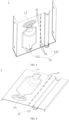
- the pipeline device 10 according to an embodiment of a first aspect of the present disclosure will now be described in detail referring to FIGS. 1-12 .
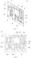
- a pipeline device 10 may include a first cover body 1 and a second cover body 2, wherein the first cover body 1 has a first fitting plate 11, and the second cover body 2 has a second fitting plate 21, wherein the first and second fitting plates 11, 21 face towards each other and fit with each other to form a first cavity 51, a second cavity 52 and an isolation portion 4, wherein the first cavity 51 and the second cavity 52 are used for the refrigerant flow, and the isolation portion 4 is located between the first cavity 51 and the second cavity 52, an arrangement path of the isolation portion 4 laterally faces towards an extension path of the first cavity 51 and an extension path of the second cavity 52 at two sides of the isolation portion 4.
- a connecting line between any two points between the first cavity 51 and the second cavity 52 passes through the isolation portion 4 to ensure that the isolation portion 4 may completely cover the area between the first cavity 51 and the second cavity 52; when an inleakage occurs at any position of the first cavity 51 and the second cavity 52 to the other cavity 5, the isolation portion 4 may accurately detect the inleakage, thereby improving the safety in use of the pipeline device 10.
- the first fitting plate 11 has a plurality of first recesses 12 hollowed in a first direction (i.e., an M direction).
- the second fitting plate 21 has a plurality of second recesses 22 hollowed in a direction opposite to the first direction (i.e., a N direction), in other words, the first recesses 12 are hollowed in a direction facing away from the second fitting plate 21, and the second recesses 22 are hollowed in a direction facing away from the first fitting plate 11.
- the second recesses 22 have a one-to-one correspondence to the first recesses 12.
- the number of the second recesses 22 is the same as that of the first recesses 12, and the positions of the second recesses 22 correspond to that of the first recesses 12 one by one; each of the second recesses 22 and the corresponding first recess 12 fit with each other to form a complete cavity 5; the second recesses 22 and the corresponding first recesses 12 fit with each other to form a plurality of complete cavities 5; the cavities 5 are isolated from each other; a refrigerant usually flows in the cavities 5; and when the pipeline device 10 is applied to a refrigeration system of a refrigeration device such as an air conditioner and a refrigerator, the refrigerant may perform a corresponding refrigeration function.
- the cavities 5 include a first cavity 51 and a second cavity 52, and the isolation portion 4 is provided on the first and second fitting plates 11, 21 between the first cavity 51 and the second cavity 52.
- the arrangement path of the isolation portion 4 ensures that the first cavity 51 and the second cavity 52 on either side may be isolated, so that the isolation portion 4 may completely cover the area between the first cavity 51 and the second cavity 52, and when an inleakage occurs at any position of the first cavity 51 and the second cavity 52 to the other cavity 5, the isolation portion 4 may accurately detect the inleakage, thereby improving the safety in use of the pipeline device 10.
- first cavity 51 may be one or more, and the number of the second cavity 52 may be one or more.
- the isolation portions 4 are provided on the first and second fitting plates 11, 21 between any two adjacent cavities 5.
- first cavities 51 and second cavities 52 are provided, and first cavities 51 and second cavities 52 adjacent to each other are isolated by the isolation portions 4.
- one first cavity 51 and one second cavity 52 are provided, and the first cavity 51 and the second cavity 52 are isolated by the isolation portion 4.
- the isolation portion 4 may include: at least one first slit 41 and at least one second slit 42, wherein the first slit 41 is provided on the first fitting plate 11 and penetrates the first fitting plate 11, and the second slit 42 is provided on the second fitting plate 21 and penetrates the second fitting plate 21.
- the first slit 41 is provided on the first fitting plate 11, the first slit 41 penetrates the first fitting plate 11 in the thickness direction (i.e., an MN direction) of the first fitting plate 11, the second slit 42 is provided on the second fitting plate 21, and the second slit 42 penetrates the second fitting plate 21 in the thickness direction (i.e., the MN direction) of the second fitting plate 21; the first slit 41 and the second slit 42 have the same arrangement path, that is, the arrangement path of the first slit 41 and the arrangement path of the second slit 42 are both the same as the arrangement path of the isolation portion 4.
- one of the at least one first slit 41 is at least partially connected to at least one of the at least one second slit 42 to form at least a part of the arrangement path of the isolation portion 4.
- the isolation portion 4 by providing the isolation portion 4, it is possible to accurately detect whether an inleakage occurs between the first cavity 51 and the second cavity 52, so that it may be ensured that the inleakage leaks from the isolation portion 4 to the outside when the inleakage penetrates the flow channels in the first cavity 51 and the second cavity 52 due to a structural defect, and the inleakage will not flow to the adjacent cavity 5 to affect the performance of the refrigeration device, and it may also be ensured that the inleakage detection in the pipeline device 10 may be completed at one time without separately detecting the flow channel of each of the first cavity 51 and the second cavity 52, which greatly improves the leakage detection efficiency of the pipeline device 10 and facilitates the determination of the inleakage point during subsequent maintenance.
- the at least one first slit 41 includes a plurality of first slit 41, and two adjacent first slit 41 are spaced apart by the first spacing portion 13, so that the first cover body 1 may be ensured to have a good strength, and the first slit 41 do not weaken the strength of the first cover body 1 too much, and at the same time, the first slit 41 are simple in structure and easy to manufacture.
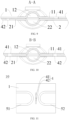
- the first spacing portion 13 is aligned with one of the at least one second slit 42, and the second slit 42 has a length not smaller than a length of the first spacing portion 13.
- the at least one second slit 42 includes a plurality of second slit 42, and two adjacent second slit 42 are spaced apart by the second spacing portion 23, so that the second cover body 2 may be ensured to have a good strength, and the second isolation portion does not weaken the strength of the second cover body 2 too much, and at the same time, the second isolation portion is simple in structure and easy to manufacture.
- the second spacing portion 23 is aligned with one of the at least one first slit 41, and the first slit 41 has a length not smaller than a length of the second spacing portion 23. For example, referring to the dimensional relationship of FIG.
- the length of the first slit 41 is L1
- the length of the second slit 42 is L2
- the length of the first spacing portion 13 is L3
- the length of the second spacing portion 23 is L4, and L1 and L4 satisfy the relationship: L1 ⁇ L4, and L2 and L3 satisfy the relationship: L2 ⁇ L3.
- the isolation portion 4 fully covers, and no blind area for an inleakage detection occurs; when communication occurs between any position of one cavity 5 and the other cavity 5 and an inleakage occurs, the refrigerant in the inleakage may overflow from the isolation portion 4 to facilitate a user to quickly locate an inleakage point.
- the first and second slit 41 and 42 may be configured as arc-shaped slits, and the first slit 41 and the second slit 42 are arranged along the same arc-shaped path, that is, the isolation portions 4 are arranged along the same arc-shaped path.
- the first slit 41 and the second slit 42 may be configured as long straight strip-shaped slits, and the first slit 41 and the the second slit 42 are arranged along the same straight path, that is, the isolation portions 4 are arranged along the same straight path.
- first slit 41 and the second slit 42 may be configured as mansarded slits, and the first slit 41 and the second slit 42 are arranged along the same mansarded path, that is, the isolation portions 4 are arranged along the same mansarded path.
- each of the first slit 41 is aligned with a part of the second slit 42 that is adjacent to the first slit 41, and is staggered with another part of the second slit 42.
- each of the second slit 42 is aligned with a part of the first slit 41 that is adjacent to the second slit 42, and is staggered with another part of the one first slit 41.
- the first slit 41 and the second slit 42 are staggered with each other, and there is a certain intersecting distance between the first slit 41 and the second slit 42 in the length direction, so that there is no blind area for inleakage detection, and it is possible to ensure that when communication occurs between the first cavity 51 and the second cavity 52, and when the refrigerant in the first cavity 51 and the second cavity 52 inleakages, the refrigerant in the inleakage may overflow from the first slit 41 or the second slit 42 and leak to the outside without the inleakage flowing to the adjacent cavity 5 affecting the performance of the refrigeration device.
- each of the first slit 41 is aligned with the second slit 42 that is adjacent to the first slit 41 by a length not greater than 1/2 of a length of the first slit 41 and not greater than 1/2 of a length of the second slit 42.
- each of the first slit 41 is aligned with the one second slit 42 adjacent to the first slit 41 by a length L5.
- L1, L5 satisfy the relational expression: L5 ⁇ L1/2, L2, L5 satisfy the relational expression: L5 ⁇ L2/2.
- each of the first slit 41 is aligned with the second slit 42 that is adjacent to the first slit 41 by a length not smaller than 1/6 of the length of the first slit 41 and not smaller than 1/6 of the length of the second slit 42.
- each of the first slit 41 is aligned with the one second slit 42 adjacent to the first slit 41 by a length L5.
- L1, L5 satisfy the relational expression: L5 ⁇ L1/6, L2, L5 satisfy the relational expression: L5 ⁇ L2/6. It is thereby possible to ensure continuity of detection between the first slit 41 and the adjacent second slit 42 without occurrence of a blind area for inleakage detection.
- the at least one first slit 41 includes a plurality of first slit 41, the first slit 41 have equal lengths, and the distances between any two adjacent first slit 41 are equal;
- the at least one second slit 42 includes a plurality of second slit 42, the second slit 42 have equal lengths, and the distances between any two adjacent second slit 42 are equal.
- each of the first slit 41 has a length L1
- each of the first spacing portion 13 between any two adjacent first slit 41 has a length L3
- each of the second slit 42 has a length L2
- each of the second spacing portion 23 between any two adjacent second slit 42 has a length L4
- the isolation portion 4 may be a whole circle configuration around the cavity 5. Referring to FIGS. 7-8 , the first cavity 51a is surrounded by the isolation portion 4a in a whole circle, so that when an inleakage occurs from the surrounded first cavity 51a to other cavities 5 or from the other cavities 5 to the first cavity 51a, the inleaked liquid overflows from the isolation portion 4a surrounding the first cavity 51a.
- the isolation portion 4 may also be of a non-whole circle construction, for example in the example shown in FIG. 8 , the isolation portion 4b is a longer segment, the extension of the isolation portion 4b is at least substantially the same as the extension of one of the cavities 5 isolated. Also, as in the example shown in FIGS. 11-12 , the isolation portion 4 is a short segment, and it is only necessary to provide the isolation portion 4 at the ends of the first cavity 51 and the second cavity 52 close to each other. In the arrangement path of the isolation portion 4, because the adjacent two cavities 5 have less risk of inleakage in the area where the isolation portion 4 is not provided, the isolation portion 4 may not be provided in the area.
- the first fitting plate 11 is fixed to the second fitting plate 21 be welding.
- the first and second fitting plates 11, 21 may be fixed by welding with the solder layer 3.
- Solder layer 3 covers the area between first fitting plate 11 and second fitting plate 21 other than the cavity 5, reducing the risk of inleakage. The solder layer 3 avoids the cavity 5, thereby preventing the solder layer 3 from entering the cavity 5 and affecting the refrigerant flow rate of the cavity 5, and also preventing the solder layer 3 from contaminating the refrigerant in the cavity 5.
- the solder layer 3 may be a solder, and when the first and second cover bodies 1, 2 need to be fixed by welding, the first cover body 1, the second cover body 2 and the solder layer 3 are brazed in an oven, and the solder is melted and flowed at a high temperature so as to fill the gap between the first and second cover bodies 1, 2, and after the solder cools and solidifies, the soldering between the first and second cover bodies 1, 2 may be completed.
- the solder flows unevenly, the inleakage between two adjacent cavities 5 between the first and second cover bodies 1, 2 are likely to occur, so that the refrigerant in one cavity 5 flows to the other cavity 5, thereby affecting the normal use of the device.
- the pipeline device 10 of an embodiment of the present disclosure is provided with the isolation portion 4, in the event of an inleakage of solder, the solder may overflow from the isolation portion 4 and leak to the outside without the inleakage flowing to the adjacent cavity 5 affecting the performance of the refrigeration device.
- first and second fitting plates 11, 21 may both be planes, so that the uniformity of the flow of the solder layer 3, when melting, between the first and second fitting plates 11, 21 may be improved, the soldering effect between the first and second fitting plates 11, 21 may be improved, and the manufacturing process of the planes is simple, which is beneficial to saving manufacturing costs.
- the first and second cover bodies 1, 2 are connected and secured by a fastener such as a bolt, a rivet, etc.
- a fastener such as a bolt, a rivet, etc.
- the first cover body 1 is provided with a first mounting hole 14
- the second cover body 2 is provided with a second mounting hole 24, and a bolt may be passed through the first mounting hole 14 and the second mounting hole 24 and then screwed with a nut so as to connect the first and second cover bodies 1, 2.
- the first mounting hole 14 is provided on the first fitting plate 11, and the second mounting hole 24 is provided on the second fitting plate 21, so that the first and second fitting plates 11, 21 may be closely fit after the first and second cover bodies 1, 2 are fastened by a fastener.
- the first and second cover bodies 1, 2 are made of stainless steel, i.e., the first and second cover bodies 1, 2 are stainless steel covers.
- Stainless steel is more rigid and less costly than red copper and copper, which is advantageous in reducing the overall cost of the pipeline device 10.
- a pipeline device 10 according to an embodiment of a second aspect of the present disclosure will now be described in detail referring to FIGS. 1-5 and 11-12 .
- a pipeline device 10 may include: a first cover body 1, a second cover body 2 and a solder layer 3.
- the first cover body 1 includes a first fitting plate 11, wherein the first fitting plate 11 has a plurality of first recesses 12 hollowed in a first direction (i.e., an M direction).
- the second cover body 2 includes a second fitting plate 21, wherein the second fitting plate 21 has a plurality of second recesses 22 hollowed in a direction opposite to the first direction (i.e., a N direction), in other words, the first recesses 12 are hollowed in a direction facing away from the second fitting plate 21, and the second recesses 22 are hollowed in a direction facing away from the first fitting plate 11.
- the second recesses 22 have a one-to-one correspondence to the first recesses 12.
- the number of the second recesses 22 is the same as that of the first recesses 12, and the positions of the second recesses 22 corresponds to that of the first recesses 12 one by one; each of the second recess 22 and the corresponding first recess 12 fit with each other to form a complete cavity 5; the second recesses 22 and the corresponding first recesses 12 fit with each other to form a plurality of complete cavities 5; the cavities 5 are isolated from each other; a refrigerant usually flows in the cavities 5; and when the pipeline device 10 is applied to a refrigeration system of a refrigeration device such as an air conditioner and a refrigerator, the refrigerant may perform a corresponding refrigeration function.
- a refrigeration system of a refrigeration device such as an air conditioner and a refrigerator
- An isolation portion 4 is provided on the first and second fitting plates 11, 21 between two adjacent cavities 5, and a length of the isolation portion 4 is not shorter than a length of any one of the two adjacent cavities 5; in this way, the isolation portion 4 may completely cover the area between the two adjacent cavities 5; and when an inleakage occurs at any position of one of the two adjacent cavities 5 to the other cavity 5, the isolation portion 4 may accurately detect the inleakage, thereby improving the safety in use of the pipeline device 10.
- the solder layer 3 is provided between the first and second fitting plates 11, 21, and the solder layer 3 is used for soldering the first and second fitting plates 11, 21.
- the solder layer 3 may be a solder, and when the first and second cover bodies 1, 2 need to be fixed by welding, the first cover body 1, the second cover body 2 and the solder layer 3 are brazed in an oven, and the solder is melted and flowed at a high temperature so as to fill the gap between the first and second cover bodies 1, 2, and after the solder cools and solidifies, the soldering between the first and second cover bodies 1, 2 may be completed.
- the pipeline device 10 of an embodiment of the present disclosure is provided with the isolation portion 4, in the event of an inleakage of solder, the solder may overflow from the isolation portion 4 and leak to the outside without the inleakage flowing to the adjacent cavity 5 affecting the performance of the refrigeration device.
- the first and second fitting plates 11, 21 may both be planes, so that the uniformity of the flow of the solder layer 3, when melting, between the first and second fitting plates 11, 21 may be improved, and the soldering effect between the first and second fitting plates 11, 21 may be improved, the manufacturing process of the planes is simple, which is beneficial to saving manufacturing costs.
- solder layer 3 avoids the cavity 5, thereby preventing the solder layer 3 from entering the cavity 5 and affecting the refrigerant flow rate of the cavity 5, and also preventing the solder layer 3 from contaminating the refrigerant in the cavity 5.
- the first recess 12 includes a first concave cavity 121 and a first groove 122
- the second recess 22 includes a second concave cavity 221 and a second groove 222, wherein the second concave cavity 221 is fitted with the first concave cavity 121 to form the first cavity 51, and the second groove 222 is fitted with the first groove 122 to form the second cavity 52.
- the solder layer 3 is provided with a first avoidance hole 31 and a second avoidance hole 32, wherein the first avoidance hole 31 is used for avoiding the first cavity 51, and the second avoidance hole 32 is used for avoiding the second cavity 52.
- the second avoidance hole 32 divides the solder layer 3 into two parts, one of which is located on the side of the second cavity 52 close to the first cavity 51 and the other of which is located on the side of the second cavity 52 facing away from the first cavity 51.
- the isolation portion 4 is located between the first cavity 51 and the second cavity 52, and the length of the isolation portion 4 is greater than that of the first cavity 51, while the length of the isolation portion 4 is greater than that of the second cavity 52.
- the connection line between any two points between the first cavity 51 and the second cavity 52 passes through the isolation portion 4 to ensure that the isolation portion 4 may completely cover the area between the first cavity 51 and the second cavity 52, and when an inleakage occurs at any position of the first cavity 51 and the second cavity 52 to the other cavity 5, the isolation portion 4 may accurately detect the inleakage, thereby improving the safety in use of the pipeline device 10.
- the term "length" as used herein refers to a dimension in a direction parallel to line AB.
- the isolation portion 4 may also be a short segment, and as shown referring to FIGS. 11 and 12 , and it is only necessary to provide the isolation portion 4 at the ends of the first cavity 51 and the second cavity 52 close to each other. In the arrangement path of the isolation portion 4, because the adjacent two cavities 5 have less risk of inleakage in the area where the isolation portion 4 is not provided, the isolation portion 4 may not be provided in the area.
- the pipeline device 10 of an embodiment of the present disclosure by providing an isolation portion 4, it is possible to accurately detect whether an inleakage occurs between two adjacent cavities 5, so that it may be ensured that the inleakage will leak from the isolation portion 4 to the outside when the inleakage penetrates the flow channels in the two adjacent cavities 5 due to a welding defect, and the inleakage will not flow to the adjacent cavities 5 to affect the performance of the refrigeration device, and it may also be ensured that the inleakage detection in the pipeline device 10 may be completed at one time, and there is no need to separately detect the flow channels of each cavity 5, which greatly improves the leakage detection efficiency of the pipeline device 10 and facilitates the determination of the inleakage point during subsequent maintenance.
- an isolation portion 4 between two adjacent cavities 5 includes a first isolation portion and a second isolation portion, wherein the first isolation portion is provided on a first fitting plate 11, the first isolation portion penetrates the first fitting plate 11 in a thickness direction (i.e., an MN direction) of the first fitting plate 11, the second isolation portion is provided on a second fitting plate 21, the second isolation portion penetrates the second fitting plate 21 in the thickness direction (i.e., the MN direction) of the second fitting plate 21, and the first isolation portion and the second isolation portion have the same arrangement path. That is, the arrangement path of the first isolation portion and the arrangement path of the second isolation portion are the same as the arrangement path of the isolation portion 4. As shown in FIGS.
- the arrangement paths of the first isolation portion and the second isolation portion each extend in a direction of a line AB.
- the first isolation portion and the second isolation portion together constitute the isolation portion 4, and a distance between a point of the first isolation portion and the second isolation portion closest to an A end and a point of the first isolation portion and the second isolation portion closest to a B end is the length of the isolation portion 4.
- the dimension of the pipeline device 10 in the direction of the line AB is the length of the isolation portion 4.
- the first isolation portion may include a plurality of intermittent first slit 41, wherein the first slit 41 are long strip-shaped slits, and the length direction of the first slit 41 extends in the direction of a line AB, the first slit 41 are arranged at intervals in the direction of the line AB, and the first spacing portion 13 is arranged between two adjacent first slit 41, so that the first cover body 1 may be ensured to have a better strength, and the first isolation portion does not weaken the strength of the first cover body 1 too much, and at the same time, the structure of the first isolation portion is simple and the processing thereof is easy.
- the second isolation portion may include a plurality of intermittent second slit 42, wherein the second slit 42 are long strip-shaped slits, and the length direction of the second slit 42 extends in the direction of the line AB, and the second slit 42 are arranged at intervals in the direction of the line AB, and the second spacing portion 23 is provided between two adjacent second slit 42, so that the second cover body 2 may be ensured to have a better strength, and the second isolation portion does not weaken the strength of the second cover body 2 too much, and at the same time, the structure of the second isolation portion is simple and the processing thereof is easy.
- the first spacing portion 13 between two adjacent first slit 41 is aligned with the second slit 42, and the second slit 42 has a length not smaller than a length of the first spacing portion 13, and the second spacing portion 23 between two adjacent second slit 42 is aligned with the first slit 41, and the first slit 41 has a length not smaller than a length of the second spacing portion 23.
- the first direction i.e., in the direction of the line MN
- the first spacing portion 13 between two adjacent first slit 41 is aligned with the second slit 42
- the second slit 42 has a length not smaller than a length of the first spacing portion 13
- the second spacing portion 23 between two adjacent second slit 42 is aligned with the first slit 41
- the first slit 41 has a length not smaller than a length of the second spacing portion 23.
- the length of the first slit 41 is L1
- the length of the second slit 42 is L2
- the length of the first spacing portion 13 is L3
- the length of the second spacing portion 23 is L4, and L1 and L4 satisfy the relationship: L1 ⁇ L4, and L2 and L3 satisfy the relationship: L2 ⁇ L3.
- the isolation portion 4 fully covers, and no blind area for an inleakage detection occurs; when communication occurs between any position of one cavity 5 and the other cavity 5 and an inleakage occurs, the refrigerant in the inleakage may overflow from the isolation portion 4 to facilitate a user to quickly locate an inleakage point.
- each of the first slit 41 is aligned with a part of the second slit 42 that is adjacent to the first slit, and each of the first slit 41 is staggered with another part of the second slit 42.
- each of the second slit 42 is aligned with a part of the first slit 41 that is adjacent to the second slit, and each of the second slit 42 is staggered with another part of the one first slit 41.
- the first slit 41 and the second slit 42 are staggered with each other, and the first slit 41 and the second slit 42 have a certain intersecting distance in the length direction, whereby it may be ensured that the inleakage will leak from the first slit 41 or the second slit 42 to the outside when the inleakage penetrates the flow channels in the adjacent two cavities 5 due to the soldering defect, without inleakaging to the adjacent cavity 5 affecting the performance of the refrigeration device.
- each of the first slit 41 is aligned with the second slit 42 that is adjacent to the first slit by a length not greater than 1/2 of a length of the first slit 41 and not greater than 1/2 of the length of the second slit 42.
- Each of the first slit 41 is aligned with the one second slit 42 adjacent to the first slit by a length L5, L1, L5 satisfy the relational expression: L5 ⁇ L1/2, L2, L5 satisfy the relational expression: L5 ⁇ L2/2.
- each of the first slit 41 is aligned with the second slit 42 that is adjacent to the first slit by a length not smaller than 1/6 of the length of the first slit 41 and not smaller than 1/6 of the length of the second slit 42.
- Each of the first slit 41 is aligned with the one second slit 42 adjacent to the first slit by a length L5, L1, L5 satisfy the relational expression: L5 ⁇ L1/6, L2, L5 satisfy the relational expression: L5 ⁇ L2/6. It is thereby possible to ensure continuity of detection between the first slit 41 and the adjacent second slit 42 without occurrence of a blind area for inleakage detection.
- the first slit 41 have equal lengths, and distances between any two adjacent first slit 41 are equal; the second slit 42 have equal lengths, and distances between any two adjacent second slit 42 are equal.
- each of the first slit 41 has a length L1
- each of the first spacing portion 13 between any two adjacent first slit 41 has a length L3
- each of the second slit 42 has a length L2
- each of the second spacing portion 23 between any two adjacent second slit 42 has a length L4
- the first and second slit 41, 42 may be configured as arc-shaped slits, and the first and second slit 41, 42 are all arranged along the same arc-shaped path.
- the solder layer 3 covers the area between the first and second fitting plates 11, 21 other than the cavity 5. As shown in FIG. 2 , the other parts of the solder layer 3, except the first avoidance hole 31 and the second avoidance hole 32, are all covered between the first and second fitting plates 11, 21, so that when the solder layer 3 melts, the area between the first and second fitting plates 11, 21 other than the cavity 5 may be fully filled, reducing the risk of inleakage.
- the material of the first and second cover bodies 1, 2 includes iron. It will be appreciated that the main material of the first and second cover bodies 1, 2 includes iron, and may also include other materials, such as carbon, so that the first and second cover bodies 1, 2 are steel covers, alternatively the first and second cover bodies 1, 2 are made of stainless steel, i.e., the first and second cover bodies 1, 2 are stainless steel covers. Of course, in some embodiments, the first and second cover bodies 1, 2 may be a pure iron cover. Iron is more rigid and less costly than red copper and copper, which is advantageous in reducing the overall cost of the pipeline device 10.
- a pipeline device 10 according to an embodiment of a third aspect of the present disclosure is described in detail below referring to FIGS. 1-10 .
- a pipeline device 10 may include a first cover body 1 and a second cover body 2, wherein the first cover body 1 has a first fitting plate 11, the second cover body 2 has a second fitting plate 21, the first and second fitting plates 11, 21 face towards each other and fit with each other to form at least one cavity 5 for the refrigerant flow and at least one isolation portion 4, the at least one isolation portion 4 is located on at least one side in the circumferential direction of the corresponding at least one cavity 5, and the isolation portion 4 has an arrangement path laterally facing towards an extension path of the corresponding cavity 5.
- the first cover body 1 has a first fitting plate 11
- the second cover body 2 has a second fitting plate 21
- the first and second fitting plates 11, 21 face towards each other and fit with each other to form at least one cavity 5 for the refrigerant flow
- at least one isolation portion 4 is located on at least one side in the circumferential direction of the corresponding at least one cavity 5
- the isolation portion 4 has an arrangement path laterally facing towards an extension path of the corresponding cavity 5.
- the cavity 5 includes a first cavity 51, which is provided with the isolation portion 4 on a side in the circumferential direction.
- a first cavity 51 which is provided with the isolation portion 4 on a side in the circumferential direction.
- each of the at least one isolation portion 4 may include: a plurality of first slit 41 and a plurality of first spacing portion 13 alternately provided on the first fitting plate 11, the first slit 41 penetrating the first fitting plate 11; and a plurality of second slit 42 and a plurality of second spacing portion 23 alternately provided on the second fitting plate 21, the second slit 42 penetrating the second fitting plate 21.
- the first slit 41 is provided on the first fitting plate 11, the first slit 41 penetrates the first fitting plate 11 in the thickness direction (i.e., an MN direction) of the first fitting plate 11, the second slit 42 is provided on the second fitting plate 21, and the second slit 42 penetrates the second fitting plate 21 in the thickness direction (i.e., an MN direction) of the second fitting plate 21; the first slit 41 and the second slit 42 have the same arrangement path, that is, the arrangement path of the first slit 41 and the arrangement path of the second slit 42 are both the same as the arrangement path of the isolation portion 4.
- the first slit 41 are provided, and two adjacent first slit 41 are spaced apart by the first spacing portion 13, so that the first cover body 1 may be ensured to have a good strength, and the first slit 41 do not weaken the strength of the first cover body 1 too much, and at the same time, the first slit 41 are simple in structure and easy to manufacture.
- the first spacing portion 13 is aligned with the second slit 42, and the second slit 42 has a length not smaller than the length of the first spacing portion 13.
- the second slit 42 are provided, and two adjacent second slit 42 are spaced apart by the second spacing portion 23, so that the second cover body 2 may be ensured to have a good strength, and the second isolation portion does not weaken the strength of the second cover body 2 too much, and at the same time, the second isolation portion is simple in structure and easy to manufacture.
- the first spacing portion 13 face towards the second slit 42, and the first slit 41 face towards the second spacing portion 23.
- the first spacing portion 13 are aligned with the second slit 42, and the second spacing portion 23 are aligned with the first slit 41.
- the isolation portion 4 When an inleakage occurs at any position of the cavity 5 to a side where the isolation portion 4 is provided, the inleaked liquid may overflow from the first slit 41 or the second slit 42, and the isolation portion 4 may accurately detect the inleakage, thereby improving the safety in use of the pipeline device 10.
- the isolation portion 4 by providing the isolation portion 4, it is possible to accurately detect whether an inleakage occurs on a side of the cavity 5 where the isolation portion 4 is provided, thereby improving the safety in use of the pipeline device 10.
- each of the first slit 41 has a length not smaller than the length of the second spacing portion 23, and each of the second slit 42 has a length not smaller than the length of the first spacing portion 13.
- the length of the first slit 41 is L1
- the length of the second slit 42 is L2
- the length of the first spacing portion 13 is L3
- the length of the second spacing portion 23 is L4, and L1 and L4 satisfy the relationship: L1 ⁇ L4, and L2 and L3 satisfy the relationship: L2 ⁇ L3.
- the isolation portion 4 may be ensured that one side of the cavity 5 in the circumferential direction is fully covered by the isolation portion 4 without a blind area for an inleakage detection , and when the inleakage occurs at any position of the cavity 5 to the side where the isolation portion 4 is provided, the refrigerant in the inleakage may overflow from the isolation portion 4, thereby facilitating the user to quickly locate the inleakage point.
- each of the first slit 41 is aligned with a part of the second slit 42 that is adjacent to the first slit, and is staggered with another part of the second slit 42.
- the first slit 41 and the second slit 42 are staggered with each other, and the first slit 41 and the second slit 42 also have a certain intersecting distance in the length direction, so that no blind area for an inleakage detection occurs, and it may be ensured that when an inleakage occurs at any position of the cavity 5 to the side where the isolation portion 4 is provided, the refrigerant in the inleakage may overflow from the first slit 41 or the second slit 42 and leak to the outside, without inleaking to the adjacent cavity 5 at the other side of the isolation portion 4 to affect the performance of the refrigeration device.
- each of the first slit 41 is aligned with the second slit 42 that is adjacent to the first slit by a length not greater than 1/2 of the length of the first slit 41 and not greater than 1/2 of the length of the second slit 42.
- each of the first slit 41 is aligned with the one second slit 42 adjacent to the first slit by a length L5, L1, L5 satisfy the relational expression: L5 ⁇ L1/2, L2, L5 satisfy the relational expression: L5 ⁇ L2/2.
- each of the first slit 41 is aligned with one of plurality of second slit 42 that is adjacent to the first slit by a length not smaller than 1/6 of the length of the first slit 41 and not smaller than 1/6 of the length of the second slit 42.
- each of the first slit 41 is aligned with the one second slit 42 adjacent to the first slit by a length L5, L1, L5 satisfy the relational expression: L5 ⁇ L1/6, L2, L5 satisfy the relational expression: L5 ⁇ L2/6. It is thereby possible to ensure continuity of detection between the first slit 41 and the adjacent second slit 42 without occurrence of a blind area for inleakage detection.
- a plurality of first slit 41 are provided, the first slit 41 have equal lengths, and distances between any two adjacent first slit 41 are equal; a plurality of second slit 42 are provided, the second slit 42 have equal lengths, and distances between any two adjacent second slit 42 are equal.
- each of the first slit 41 has a length L1
- each of the first spacing portion 13 between any two adjacent first slit 41 has a length L3
- each of the second slit 42 has a length L2
- each of the second spacing portion 23 between any two adjacent second slit 42 has a length L4
- the first fitting plate 11 is fixed to the second fitting plate 21 by welding.
- the first and second fitting plates 11, 21 may be fixed by welding with the solder layer 3.
- Solder layer 3 covers the area between first fitting plate 11 and second fitting plate 21 other than the cavity 5, reducing the risk of inleakage. The solder layer 3 avoids the cavity 5, thereby preventing the solder layer 3 from entering the cavity 5 and affecting the refrigerant flow rate of the cavity 5, and also preventing the solder layer 3 from contaminating the refrigerant in the cavity 5.
- the solder layer 3 may be a solder, and when the first and second cover bodies 1, 2 need to be fixed by welding, the first cover body 1, the second cover body 2 and the solder layer 3 are brazed in an oven, and the solder is melted and flowed at a high temperature so as to fill the gap between the first and second cover bodies 1, 2, and when the solder cools and solidifies, the soldering between the first and second cover bodies 1, 2 may be completed.
- the solder flows unevenly, the inleakage between two adjacent cavities 5 between the first and second cover bodies 1, 2 are likely to occur, so that the refrigerant in one cavity 5 flows to the other cavity 5, thereby affecting the normal use of the device.
- first and second fitting plates 11, 21 may both be planes, so that the uniformity of the flow of the solder layer 3, when melting, between the first and second fitting plates 11, 21 may be improved, the soldering effect between the first and second fitting plates 11, 21 may be improved, and the manufacturing process of the planes is simple, which is beneficial to saving manufacturing costs.
- first and second cover bodies 1, 2 are connected and secured by a fastener such as a bolt, a rivet, etc.
- the first and second cover bodies 1, 2 are made of stainless steel, i.e., the first and second cover bodies 1, 2 are stainless steel covers.
- Stainless steel is more rigid and less costly than red copper and copper, which is advantageous in reducing the overall cost of the pipeline device 10.
- the pipeline device 10 according to an embodiment of the fourth aspect of the present disclosure will now be described in detail referring to FIGS. 6-10 .
- a pipeline device 10 may include a first cover body 1 and a second cover body 2, wherein the first cover body 1 has a first fitting plate 11, and the second cover body 2 has a second fitting plate 21, wherein the first and second fitting plates 11, 21 face towards each other and fit with each other to form a cavity 5 and an isolation portion 4, wherein the cavity 5 is used for the refrigerant flow, and the isolation portion 4 is circumferentially arranged on a periphery of the cavity 5, so that when an inleakage occurs from the surrounded cavity 5 to other cavities or from the other cavities to the cavity 5, an inleaked liquid will overflow from the isolation portion 4 surrounding the cavity 5.
- the cavity 5 includes a first cavity 51a, the first cavity 51a is surrounded by the isolation portion 4a in a whole circle, so that when an inleakage occurs from the surrounded first cavity 51a to the other cavities 5 or from the other cavities 5 to the first cavity 51a, the inleaked liquid overflows from the isolation portion 4a surrounding the first cavity 51a.
- the isolation portion 4 may include a plurality of first slit 41 and a plurality of second slit 42.
- the first slit 41 are provided on the first fitting plate 11 and penetrates the first fitting plate 11, and the first slit 41 are configured to be provided at intervals along an arrangement path of the isolation portion 4.
- the second slit 42 are provided on the second fitting plate 21 and penetrates the second fitting plate 21, and the second slit 42 are configured to be provided at intervals along an arrangement path of the isolation portion 4.
- the first slit 41 is provided on the first fitting plate 11, the first slit 41 penetrates the first fitting plate 11 in the thickness direction (i.e., an MN direction) of the first fitting plate 11, the second slit 42 is provided on the second fitting plate 21, and the second slit 42 penetrates the second fitting plate 21 in the thickness direction (i.e., an MN direction) of the second fitting plate 21; the first slit 41 and the second slit 42 have the same arrangement path, that is, the arrangement path of the first slit 41 and the arrangement path of the second slit 42 are both the same as the arrangement path of the isolation portion 4.
- the first slit 41 and the second slit 42 are alternately provided along the arrangement path of the isolation portion 4, a head end and a tail end of each of the first slit 41 at least partially overlap two second slit 42 that are adjacent to the first slit, and a head end and a tail end of each of the second slit 42 at least partially overlap two adjacent first slit 41 that are adjacent to the first slit.
- the isolation portion 4 circumferentially arranged on the periphery of the cavity 5, it is possible to accurately detect whether or not an inleakage occurs in the cavity 5, thereby improving the safety in use of the pipeline device 10.
- each of the first slit 41 overlaps with the second slit 42 that is adjacent to the first slit by a length not greater than 1/2 of the length of the first slit 41 and not greater than 1/2 of the length of the second slit 42.
- each of the first slit 41 is aligned with the one second slit 42 adjacent to the first slit by a length L5, L1, L5 satisfy the relational expression: L5 ⁇ L1/2, L2, L5 satisfy the relational expression: L5 ⁇ L2/2.
- each of the first slit 41 overlaps with the second slit 42 that is adjacent to the first slit by a length not smaller than 1/6 of the length of the first slit 41 and not smaller than 1/6 of the length of the second slit 42.
- each of the first slit 41 is aligned with the one second slit 42 adjacent to the first slit by a length L5, L1, L5 satisfy the relational expression: L5 ⁇ L1/6, L2, L5 satisfy the relational expression: L5 ⁇ L2/6. It is thereby possible to ensure continuity of detection between the first slit 41 and the adjacent second slit 42 without occurrence of a blind area for inleakage detection.
- the first slit 41 have equal lengths, and distances between any two adjacent first slit 41 are equal; the second slit 42 have equal lengths, and distances between any two adjacent second slit 42 are equal.
- each of the first slit 41 has a length L1
- each of the first spacing portion 13 between any two adjacent first slit 41 has a length L3
- each of the second slit 42 has a length L2
- each of the second spacing portion 23 between any two adjacent second slit 42 has a length L4
- the first fitting plate 11 is fixed to the second fitting plate 21 by welding.
- the first and second fitting plates 11, 21 may be fixed by welding with the solder layer 3.
- Solder layer 3 covers the area between first fitting plate 11 and second fitting plate 21 other than the cavity 5, reducing the risk of inleakage. The solder layer 3 avoids the cavity 5, thereby preventing the solder layer 3 from entering the cavity 5 and affecting the refrigerant flow rate of the cavity 5, and also preventing the solder layer 3 from contaminating the refrigerant in the cavity 5.
- the solder layer 3 may be a solder, and when the first and second cover bodies 1, 2 need to be fixed by welding, the first cover body 1, the second cover body 2 and the solder layer 3 are brazed in an oven, and the solder is melted and flowed at a high temperature so as to fill the gap between the first and second cover bodies 1, 2, and when the solder cools and solidifies, the soldering between the first and second cover bodies 1, 2 may be completed.
- the solder flows unevenly, the inleakage between two adjacent cavities 5 between the first and second cover bodies 1, 2 are likely to occur, so that the refrigerant in one cavity 5 flows to the other cavity 5, thereby affecting the normal use of the device.
- first and second fitting plates 11, 21 may both be planes, so that the uniformity of the flow of the solder layer 3, when melting, between the first and second fitting plates 11, 21 may be improved, the soldering effect between the first and second fitting plates 11, 21 may be improved, and the manufacturing process of the planes is simple, which is beneficial to saving manufacturing costs.
- first and second cover bodies 1, 2 are connected and secured by a fastener such as a bolt, a rivet, etc.
- the first and second cover bodies 1, 2 are made of stainless steel, i.e., the first and second cover bodies 1, 2 are stainless steel covers.
- Stainless steel is more rigid and less costly than red copper and copper, which is advantageous in reducing the overall cost of the pipeline device 10.
- a refrigeration system includes the pipeline device 10 of the above-described embodiment.
- the refrigeration system may be a refrigeration system of an air conditioner, a refrigeration system of a refrigerator, or a refrigeration system of another device having a refrigeration function.
Landscapes
- Engineering & Computer Science (AREA)
- Mechanical Engineering (AREA)
- General Engineering & Computer Science (AREA)
- Chemical & Material Sciences (AREA)
- Combustion & Propulsion (AREA)
- Physics & Mathematics (AREA)
- Thermal Sciences (AREA)
- Cooling Or The Like Of Electrical Apparatus (AREA)
- Examining Or Testing Airtightness (AREA)
Abstract
Description
- This application claims priority to
Chinese Patent Application No. 202221615067.2, filed on June 24, 2022 - The present disclosure relates to the technical field of refrigeration systems, and more particularly, to a pipeline device and a refrigeration system having same.
- A pipeline device in an air conditioner generally fixes an upper cover and a lower cover by welding, wherein the upper cover and the lower cover both have a plurality of cavity halves, and after fixing the upper cover and the lower cover, the cavity halves on the upper cover and the lower cover form a plurality of complete cavities, and these cavities are used for circulating a refrigerant. A solder is laid between the upper cover and the lower cover and is used for fixing the upper cover and the lower cover by welding. However, whether there is an inleakage between two adjacent cavities cannot be determined from the outside, which makes it difficult to detect the inleakage of the pipeline device, and an inleakage point cannot be determined during the after-sales repair.
- The present disclosure aims to solve, to some extent, at least one of the above-mentioned technical problems in the prior art. For this reason, the present disclosure provides a pipeline device for facilitating inleakage detection.
- The present disclosure also provides another pipeline device.
- The present disclosure also provides yet another pipeline device.
- The present disclosure also provides still yet another pipeline device.
- The present disclosure also provides a refrigeration system having a pipeline device as described above.
- The pipeline device according to an embodiment of a first aspect of the present disclosure includes: a first cover body and a second cover body, wherein the first cover body has a first fitting plate, the second cover body has a second fitting plate, wherein the first fitting plate and the second fitting plate face towards each other and fit with each other to form a first cavity and a second cavity for a refrigerant flow, and an isolation portion located between the first cavity and the second cavity, wherein an arrangement path of the isolation portion laterally faces towards an extension path of the first cavity and an extension path of the second cavity at two sides of the isolation portion; the isolation portion includes: at least one first slit and at least one second slit, at least one first slit provided on the first fitting plate and penetrating the first fitting plate; at least one second slit provided on the second fitting plate and penetrating the second fitting plate; wherein on a planar projection parallel to fitting surface of the first fitting plate and the second fitting plate, one of the at least one first slit is at least partially connected to at least one of the at least one second slit to form at least a part of the arrangement path of the isolation portion.
- The pipeline device according to an embodiment of the present disclosure, it is possible to accurately detect whether an inleakage has occurred between the first cavity and the second cavity by providing the isolation portion, thereby improving the safety in use of the pipeline device.
- According to some embodiments of the present disclosure, the at least one first slit comprises a plurality of first slit, two adjacent first slit being spaced apart by a first spacing portion, the first spacing portion being aligned with one of the at least one second slit having a length not smaller than a length of the first spacing portion; and the at least one second slit comprises a plurality of second slit, two adjacent second slit being spaced apart by a second spacing portion, the second spacing portion being aligned with one of the at least one first slit having a length not smaller than a length of the second spacing portion.
- According to some embodiments of the present disclosure, in a direction perpendicular to the fitting surface of the first fitting plate and the second fitting plate, each of the at least one first slit is aligned with a part of one of the at least one second slit that is adjacent to the first slit, and is staggered with another part of the second slit.
- According to some embodiments of the present disclosure, each of the at least one first slit is aligned with the one second slit adjacent to the first slit by a length not greater than 1/2 of a length of the first slit and not greater than 1/2 of a length of the second slit.
- According to some embodiments of the present disclosure, each of the at least one first slit is aligned with the one second slit adjacent to the first slit by a length not smaller than 1/6 of the length of the first slit and not smaller than 1/6 of the length of the second slit.
- According to some embodiments of the present disclosure, the at least one first slit comprises a plurality of first slit having equal lengths, distances between any two adjacent first slit being equal; and the at least one second slit comprises a plurality of second slit having equal lengths, distances between any two adjacent second slit being equal.
- According to some embodiments of the present disclosure, the first fitting plate is fixed to the second fitting plate by welding or connected to the second fitting plate by using a fastener.
- According to some embodiments of the present disclosure, the first cover body and the second cover body are made of stainless steel.
- The pipeline device according to an embodiment of a second aspect of the present disclosure includes: a first cover body comprising a first fitting plate, the first fitting plate having a plurality of first recesses hollowed in a first direction; a second cover body comprising a second fitting plate, the second fitting plate having a plurality of second recesses hollowed in a direction opposite to the first direction, wherein the second recesses have a one-to-one correspondence to the first recesses, wherein each of the second recesses and the corresponding first recess fit with each other to form a complete cavity, wherein an isolation portion is provided on the first fitting plate and the second fitting plate between two adjacent cavities, and wherein a length of the isolation portion is not shorter than a length of any one of the two adjacent cavities; and a solder layer provided between the first fitting plate and second fitting plate and used for soldering the first fitting plate and the second fitting plate, wherein the solder layer avoids the cavity.
- For the pipeline device according to an embodiment of the present disclosure, by providing the isolation portion, it is possible to accurately detect whether an inleakage occurs between two adjacent cavities, thereby improving the safety in use of the pipeline device.
- According to some embodiments of the present disclosure, the isolation portions between the two adjacent cavities comprise a first isolation portion provided on the first fitting plate and a second isolation portion provided on the second fitting plate, the first isolation portion and the second isolation portion having a same arrangement path.
- According to some embodiments of the present disclosure, the first isolation portion comprises a plurality of intermittent first slit; the second isolation portion comprises a plurality of intermittent second slit; in the first direction, a first spacing portion between two adjacent first slit is aligned with one of the intermittent second slit having a length not smaller than a length of the first spacing portion, and a second spacing portion between two adjacent second slit is aligned with one of the intermittent first slit having a length not smaller than a length of the second spacing portion.
- According to some embodiments of the present disclosure, in the first direction, each of the first slit is aligned with a part of the second slit that is adjacent to the first slit, and is staggered with another part of the second slit.
- According to some embodiments of the present disclosure, each of the first slit is aligned with the second slit that is adjacent to the first slit by a length not greater than 1/2 of the length of the first slit and not greater than 1/2 of the length of the second slit.
- According to some embodiments of the present disclosure, each of the first slit is aligned with the second slit that is adjacent to the first slit by a length not smaller than 1/6 of the length of the first slit and not smaller than 1/6 of the length of the second slit.
- According to some embodiments of the present disclosure, the first slit has equal lengths, distances between any two adjacent first slit being equal; and the second slit has equal lengths, distances between any two adjacent second slit being equal.
- According to some embodiments of the present disclosure, the solder layer covers an area between the first fitting plate and the second fitting plate other than the cavity.
- According to some embodiments of the present disclosure, the first cover body and the second cover body are made of stainless steel.
- The pipeline device according to an embodiment of a third aspect of the present disclosure includes: a first cover body having a first fitting plate; a second cover body having a second fitting plate, wherein the first fitting plate and the second fitting plate face towards each other and fit with each other to form at least one cavity for a refrigerant flow and at least one isolation portion, the at least one isolation portion being located on at least one side of a circumferential direction of the at least one cavity, and the isolation portion having an arrangement path laterally facing towards an extension path of the corresponding cavity; wherein each of the at least one isolation portion comprises: a plurality of first slit and a plurality of first spacing portion alternately provided on the first fitting plate, the first slit penetrating the first fitting plate; and a plurality of second slit and a plurality of second spacing portion alternately provided on the second fitting plate, the second slit penetrating the second fitting plate, wherein in a direction perpendicular to fitting surface of the first fitting plate and the second fitting plate, the first spacing portion face towards the second slit, and the first slit face towards the second spacing portion.
- The pipeline device according to an embodiment of the present disclosure, by providing the isolation portion, it is possible to accurately detect whether an inleakage occurs on a side of the cavity where the isolation portion is provided, thereby improving the safety in use of the pipeline device.
- According to some embodiments of the present disclosure, each of the first slit has a length not smaller than a length of the second spacing portion, and each of the second slit has a length not smaller than a length of the first spacing portion.
- According to some embodiments of the present disclosure, in a direction perpendicular to the fitting surface of the first fitting plate and the second fitting plate, each of the first slit is aligned with a part of the second slit that is adjacent to the first slit, and is staggered with another part of the second slit.
- According to some embodiments of the present disclosure, each of the first slit is aligned with the second slit that is adjacent to the first slit by a length not greater than 1/2 of a length of the first slit and not greater than 1/2 of a length of the second slit.
- According to some embodiments of the present disclosure, each of the first slit is aligned with the second slit that is adjacent to the first slit by a length no smaller than 1/6 of a length of the first slit and not smaller than 1/6 of a length of the second slit.
- According to some embodiments of the present disclosure, a plurality of first slit is provided and has equal lengths, distances between any two adjacent first slit being equal; and a plurality of second slit is provided and has equal lengths, distances between any two adjacent second slit being equal.
- According to some embodiments of the present disclosure, the first fitting plate is fixed to the second fitting plate by welding or connected to the second fitting plate by using a fastener.
- According to some embodiments of the present disclosure, the first cover body and the second cover body are made of stainless steel.
- The pipeline device according to an embodiment of a fourth aspect of the present disclosure includes: a first cover body having a first fitting plate; and a second cover body having a second fitting plate, wherein the first fitting plate and the second fitting plate face towards each other and fit with each other to form a cavity for a refrigerant flow and an isolation portion, the isolation portion being circumferentially arranged on a periphery of the cavity; wherein the isolation portion comprises: a plurality of first slit provided on the first fitting plate and penetrating the first fitting plate and configured to be provided at intervals along an arrangement path of the isolation portion; a plurality of second slit provided on the second fitting plate and penetrating the second fitting plate and configured to be provided at intervals along the arrangement path of the isolation portion; wherein on a planar projection parallel to fitting surface of the first fitting plate and the second fitting plate, the first slit and the second slit are alternately provided along the arrangement path of the isolation portion; wherein a head end and a tail end of each of the first slit at least partially overlap two second slit of the second slit that are adjacent to the first slit; and wherein a head end and a tail end of each of the second slit at least partially overlap two first slit of the first slit that are adjacent to the second slit.
- The pipeline device according to an embodiment of the present disclosure, by providing an isolation portion circumferentially arranged on the periphery of the cavity, it is possible to accurately detect whether an inleakage occurs in the cavity, thereby improving the safety in use of the pipeline device.
- According to some embodiments of the present disclosure, each of the first slit overlaps with the second slit that is adjacent to the first slit by a length not greater than 1/2 of a length of the first slit and not greater than 1/2 of a length of the second slit.
- According to some embodiments of the present disclosure, each of the first slit overlaps with the second slit that is adjacent to the first slit by a length not smaller than 1/6 of a length of the first slit and not smaller than 1/6 of a length of the second slit.
- According to some embodiments of the present disclosure, the first slit has equal lengths, distances between any two adjacent first slit being equal; the second slit has equal lengths, distances between any two adjacent second slit being equal.
- According to some embodiments of the present disclosure, the first fitting plate is fixed to the second fitting plate by welding or connected to the second fitting plate by using a fastener.
- According to some embodiments of the present disclosure, the first cover body and the second cover body are made of stainless steel.
- A refrigeration system according to an embodiment of a fifth aspect of the present disclosure includes the above-described pipeline device.
- The refrigeration system has the same advantages as the above-described pipeline device with respect to the prior art and will not be described again here.
- Additional aspects and advantages in accordance with the present disclosure will be set forth in part in the description which follows and, in part, will be obvious from the description, or may be learned by practice of the application.
-
-
FIG. 1 is a schematic assembly view of a pipeline device according to one embodiment of the present disclosure; -
FIG. 2 is an exploded view of the pipeline device as shown inFIG. 1 ; -
FIG. 3 is a perspective view of a first cover body; -
FIG. 4 is a perspective view of a second cover body; -
FIG. 5 is a schematic diagram showing the relative positional relationship between the first slit and the second slit; -
FIG. 6 is a schematic assembly view of a pipeline device according to another embodiment of the present disclosure; -
FIG. 7 is an exploded view of the pipeline device as shown inFIG. 6 ; -
FIG. 8 is a front view of the pipeline device as shown inFIG. 6 ; -
FIG. 9 is a cross-sectional view at A-A inFIG. 8 ; -
FIG. 10 is a cross-sectional view at B-B inFIG. 8 ; -
FIG. 11 is a front view of a pipeline device according to yet another embodiment of the present disclosure; and -
FIG. 12 is a front view of a pipeline device according to yet another embodiment of the present disclosure. -
pipeline device 10;first cover body 1; firstfitting plate 11;first recess 12; firstconcave cavity 121;first groove 122;first spacing portion 13; first mountinghole 14;second cover body 2; secondfitting plate 21;second recess 22; secondconcave cavity 221;second groove 222;second spacing portion 23; second mountinghole 24;solder layer 3;first avoidance hole 31;second avoidance hole 32;isolation portion 4; first slit 41; second slit 42;cavity 5;first cavity 51;second cavity 52. - Reference will now be made in detail to the embodiments of the present disclosure, examples of which are illustrated in the accompanying drawings, wherein like reference numerals refer to the same or similar elements throughout the several views, and wherein like reference numerals refer to elements having the same or similar functions throughout the several views. The embodiments described below referring to the figures are exemplary and are intended to be illustrative of the present disclosure and are not to be construed as limiting the present disclosure.
- In describing the present disclosure, it is to be understood that the terms "longitudinal", "lateral", "length", "width", "thickness", "upper", "lower", "front", "rear", "left", "right", "vertical", "horizontal", "top", "bottom", "inner", "outer", and the like, indicate orientations or positional relationships based on the orientations or positional relationships shown in the drawings, are merely for convenience in describing the present disclosure and simplifying the description, and do not indicate or imply that the device or element referred to must have a particular orientation, be constructed in a particular orientation, and be operated, and therefore, should not be construed as limiting the present disclosure.
- Further, the terms "first" and "second" are used for descriptive purposes only and are not to be construed as indicating or implying relative importance or implicitly indicating the number of technical features indicated. Thus, a feature defined as "first" or "second" may explicitly or implicitly include one or more of the stated features. In the description of the present disclosure, "a plurality of' refers to at least two, e.g., two, three, etc. unless specifically and specifically limited otherwise.
- In the present disclosure, unless explicitly stipulated and limited otherwise, the terms "mounted", "coupled", "connected", "secured" and the like are to be understood in a broad sense, for example, they may be fixed connected or detachably connected, or integrated; may be a mechanical connection or an electrical connection; it may be directly connected or indirectly connected through an intermediate medium, and may be the communication between two elements or the interaction relationship between two elements. The specific meaning of the above terms in the present disclosure may be understood by a person skilled in the art as the case may be.
- The
pipeline device 10 according to an embodiment of a first aspect of the present disclosure will now be described in detail referring toFIGS. 1-12 . - With reference to
FIGS. 1 and7-8 , apipeline device 10 according to an embodiment of a first aspect of the present disclosure may include afirst cover body 1 and asecond cover body 2, wherein thefirst cover body 1 has a firstfitting plate 11, and thesecond cover body 2 has a secondfitting plate 21, wherein the first and secondfitting plates first cavity 51, asecond cavity 52 and anisolation portion 4, wherein thefirst cavity 51 and thesecond cavity 52 are used for the refrigerant flow, and theisolation portion 4 is located between thefirst cavity 51 and thesecond cavity 52, an arrangement path of theisolation portion 4 laterally faces towards an extension path of thefirst cavity 51 and an extension path of thesecond cavity 52 at two sides of theisolation portion 4. That is to say, a connecting line between any two points between thefirst cavity 51 and thesecond cavity 52 passes through theisolation portion 4 to ensure that theisolation portion 4 may completely cover the area between thefirst cavity 51 and thesecond cavity 52; when an inleakage occurs at any position of thefirst cavity 51 and thesecond cavity 52 to theother cavity 5, theisolation portion 4 may accurately detect the inleakage, thereby improving the safety in use of thepipeline device 10. - Referring to
FIGS. 2-4 and6 , the firstfitting plate 11 has a plurality offirst recesses 12 hollowed in a first direction (i.e., an M direction). The secondfitting plate 21 has a plurality ofsecond recesses 22 hollowed in a direction opposite to the first direction (i.e., a N direction), in other words, thefirst recesses 12 are hollowed in a direction facing away from the secondfitting plate 21, and thesecond recesses 22 are hollowed in a direction facing away from the firstfitting plate 11. The second recesses 22 have a one-to-one correspondence to the first recesses 12. In some embodiments, the number of the second recesses 22 is the same as that of thefirst recesses 12, and the positions of thesecond recesses 22 correspond to that of thefirst recesses 12 one by one; each of thesecond recesses 22 and the correspondingfirst recess 12 fit with each other to form acomplete cavity 5; thesecond recesses 22 and the correspondingfirst recesses 12 fit with each other to form a plurality ofcomplete cavities 5; thecavities 5 are isolated from each other; a refrigerant usually flows in thecavities 5; and when thepipeline device 10 is applied to a refrigeration system of a refrigeration device such as an air conditioner and a refrigerator, the refrigerant may perform a corresponding refrigeration function. - The
cavities 5 include afirst cavity 51 and asecond cavity 52, and theisolation portion 4 is provided on the first and secondfitting plates first cavity 51 and thesecond cavity 52. The arrangement path of theisolation portion 4 ensures that thefirst cavity 51 and thesecond cavity 52 on either side may be isolated, so that theisolation portion 4 may completely cover the area between thefirst cavity 51 and thesecond cavity 52, and when an inleakage occurs at any position of thefirst cavity 51 and thesecond cavity 52 to theother cavity 5, theisolation portion 4 may accurately detect the inleakage, thereby improving the safety in use of thepipeline device 10. - It should be noted that the number of the
first cavity 51 may be one or more, and the number of thesecond cavity 52 may be one or more. Theisolation portions 4 are provided on the first and secondfitting plates adjacent cavities 5. - For example, in an embodiment shown in
FIGS. 7-8 , a plurality offirst cavities 51 and a plurality ofsecond cavities 52 are provided, andfirst cavities 51 andsecond cavities 52 adjacent to each other are isolated by theisolation portions 4. - Also, in an embodiment shown in
FIG. 1 , onefirst cavity 51 and onesecond cavity 52 are provided, and thefirst cavity 51 and thesecond cavity 52 are isolated by theisolation portion 4. - Referring to
FIGS. 2-4 , as shown inFIG. 6 , theisolation portion 4 may include: at least onefirst slit 41 and at least onesecond slit 42, wherein thefirst slit 41 is provided on the firstfitting plate 11 and penetrates the firstfitting plate 11, and thesecond slit 42 is provided on the secondfitting plate 21 and penetrates the secondfitting plate 21. In some embodiments, thefirst slit 41 is provided on the firstfitting plate 11, thefirst slit 41 penetrates the firstfitting plate 11 in the thickness direction (i.e., an MN direction) of the firstfitting plate 11, thesecond slit 42 is provided on the secondfitting plate 21, and thesecond slit 42 penetrates the secondfitting plate 21 in the thickness direction (i.e., the MN direction) of the secondfitting plate 21; thefirst slit 41 and thesecond slit 42 have the same arrangement path, that is, the arrangement path of thefirst slit 41 and the arrangement path of thesecond slit 42 are both the same as the arrangement path of theisolation portion 4. - On a planar projection parallel to the fitting surface of the first and second
fitting plates first slit 41 is at least partially connected to at least one of the at least one second slit 42 to form at least a part of the arrangement path of theisolation portion 4. In other words, there is a certain intersecting distance between thefirst slit 41 and thesecond slit 42 on the arrangement path of theisolation portion 4, so that it is possible to avoid a situation where there is a blind area for inleakage detection when thefirst slit 41 and thesecond slit 42 do not intersect, i.e., there is no blind area for inleakage detection, and it is possible to ensure that when communication occurs between thefirst cavity 51 and thesecond cavity 52, and when the refrigerant in thefirst cavity 51 and thesecond cavity 52 inleakages, the refrigerant in the inleakage may overflow from thefirst slit 41 or thesecond slit 42 and leak to the outside without the inleakage flowing to theadjacent cavity 5 affecting the performance of the refrigeration device. - According to the
pipeline device 10 of an embodiment of the present disclosure, by providing theisolation portion 4, it is possible to accurately detect whether an inleakage occurs between thefirst cavity 51 and thesecond cavity 52, so that it may be ensured that the inleakage leaks from theisolation portion 4 to the outside when the inleakage penetrates the flow channels in thefirst cavity 51 and thesecond cavity 52 due to a structural defect, and the inleakage will not flow to theadjacent cavity 5 to affect the performance of the refrigeration device, and it may also be ensured that the inleakage detection in thepipeline device 10 may be completed at one time without separately detecting the flow channel of each of thefirst cavity 51 and thesecond cavity 52, which greatly improves the leakage detection efficiency of thepipeline device 10 and facilitates the determination of the inleakage point during subsequent maintenance. - In some embodiments of the present disclosure, as shown referring to
FIGS. 3-5 , the at least onefirst slit 41 includes a plurality offirst slit 41, and two adjacentfirst slit 41 are spaced apart by thefirst spacing portion 13, so that thefirst cover body 1 may be ensured to have a good strength, and thefirst slit 41 do not weaken the strength of thefirst cover body 1 too much, and at the same time, thefirst slit 41 are simple in structure and easy to manufacture. Thefirst spacing portion 13 is aligned with one of the at least onesecond slit 42, and thesecond slit 42 has a length not smaller than a length of thefirst spacing portion 13. Similarly, the at least onesecond slit 42 includes a plurality ofsecond slit 42, and two adjacentsecond slit 42 are spaced apart by thesecond spacing portion 23, so that thesecond cover body 2 may be ensured to have a good strength, and the second isolation portion does not weaken the strength of thesecond cover body 2 too much, and at the same time, the second isolation portion is simple in structure and easy to manufacture. Thesecond spacing portion 23 is aligned with one of the at least onefirst slit 41, and thefirst slit 41 has a length not smaller than a length of thesecond spacing portion 23. For example, referring to the dimensional relationship ofFIG. 5 , the length of thefirst slit 41 is L1, the length of thesecond slit 42 is L2, the length of thefirst spacing portion 13 is L3, and the length of thesecond spacing portion 23 is L4, and L1 and L4 satisfy the relationship: L1≥L4, and L2 and L3 satisfy the relationship: L2≥L3. In this way, it is ensured that between thefirst cavity 51 and thesecond cavity 52, theisolation portion 4 fully covers, and no blind area for an inleakage detection occurs; when communication occurs between any position of onecavity 5 and theother cavity 5 and an inleakage occurs, the refrigerant in the inleakage may overflow from theisolation portion 4 to facilitate a user to quickly locate an inleakage point. - Alternatively, referring to
FIG. 6 , the first andsecond slit first slit 41 and thesecond slit 42 are arranged along the same arc-shaped path, that is, theisolation portions 4 are arranged along the same arc-shaped path. - Alternatively, referring to
FIG. 5 , thefirst slit 41 and thesecond slit 42 may be configured as long straight strip-shaped slits, and thefirst slit 41 and the thesecond slit 42 are arranged along the same straight path, that is, theisolation portions 4 are arranged along the same straight path. - Alternatively, the
first slit 41 and thesecond slit 42 may be configured as mansarded slits, and thefirst slit 41 and thesecond slit 42 are arranged along the same mansarded path, that is, theisolation portions 4 are arranged along the same mansarded path. - In some embodiments of the present disclosure, referring to
FIGS. 5-6 and8-10 , in a direction perpendicular to the fitting surface of the first andsecond mating panels first slit 41 is aligned with a part of thesecond slit 42 that is adjacent to thefirst slit 41, and is staggered with another part of thesecond slit 42. Similarly, each of thesecond slit 42 is aligned with a part of thefirst slit 41 that is adjacent to thesecond slit 42, and is staggered with another part of the onefirst slit 41. In other words, thefirst slit 41 and thesecond slit 42 are staggered with each other, and there is a certain intersecting distance between thefirst slit 41 and thesecond slit 42 in the length direction, so that there is no blind area for inleakage detection, and it is possible to ensure that when communication occurs between thefirst cavity 51 and thesecond cavity 52, and when the refrigerant in thefirst cavity 51 and thesecond cavity 52 inleakages, the refrigerant in the inleakage may overflow from thefirst slit 41 or thesecond slit 42 and leak to the outside without the inleakage flowing to theadjacent cavity 5 affecting the performance of the refrigeration device. - In some embodiments of the present disclosure, each of the
first slit 41 is aligned with thesecond slit 42 that is adjacent to thefirst slit 41 by a length not greater than 1/2 of a length of thefirst slit 41 and not greater than 1/2 of a length of thesecond slit 42. Referring to the dimensional relationship ofFIG. 5 , each of thefirst slit 41 is aligned with the one second slit 42 adjacent to thefirst slit 41 by a length L5. L1, L5 satisfy the relational expression: L5 ≤ L1/2, L2, L5 satisfy the relational expression: L5≤L2/2. Thus, it is possible to prevent the first andsecond slit second cover bodies - In some embodiments of the present disclosure, each of the
first slit 41 is aligned with thesecond slit 42 that is adjacent to thefirst slit 41 by a length not smaller than 1/6 of the length of thefirst slit 41 and not smaller than 1/6 of the length of thesecond slit 42. Referring to the dimensional relationship ofFIG. 5 , each of thefirst slit 41 is aligned with the one second slit 42 adjacent to thefirst slit 41 by a length L5. L1, L5 satisfy the relational expression: L5≥L1/6, L2, L5 satisfy the relational expression: L5≥L2/6. It is thereby possible to ensure continuity of detection between thefirst slit 41 and the adjacentsecond slit 42 without occurrence of a blind area for inleakage detection. - In some embodiments of the present disclosure, the at least one
first slit 41 includes a plurality offirst slit 41, thefirst slit 41 have equal lengths, and the distances between any two adjacentfirst slit 41 are equal; the at least onesecond slit 42 includes a plurality ofsecond slit 42, thesecond slit 42 have equal lengths, and the distances between any two adjacentsecond slit 42 are equal. In other words, referring toFIG. 5 , each of thefirst slit 41 has a length L1, each of thefirst spacing portion 13 between any two adjacentfirst slit 41 has a length L3, each of thesecond slit 42 has a length L2, and each of thesecond spacing portion 23 between any two adjacentsecond slit 42 has a length L4, so that the distances between thefirst slit 41 and distances between thesecond slit 42 may be made uniform, the machining may be facilitated, the machining process may be simplified, and the manufacturing cost may be saved. - In some embodiments of the present disclosure, the
isolation portion 4 may be a whole circle configuration around thecavity 5. Referring toFIGS. 7-8 , thefirst cavity 51a is surrounded by theisolation portion 4a in a whole circle, so that when an inleakage occurs from the surroundedfirst cavity 51a toother cavities 5 or from theother cavities 5 to thefirst cavity 51a, the inleaked liquid overflows from theisolation portion 4a surrounding thefirst cavity 51a. - In other embodiments of the present disclosure, the
isolation portion 4 may also be of a non-whole circle construction, for example in the example shown inFIG. 8 , theisolation portion 4b is a longer segment, the extension of theisolation portion 4b is at least substantially the same as the extension of one of thecavities 5 isolated. Also, as in the example shown inFIGS. 11-12 , theisolation portion 4 is a short segment, and it is only necessary to provide theisolation portion 4 at the ends of thefirst cavity 51 and thesecond cavity 52 close to each other. In the arrangement path of theisolation portion 4, because the adjacent twocavities 5 have less risk of inleakage in the area where theisolation portion 4 is not provided, theisolation portion 4 may not be provided in the area. - In some embodiments of the present disclosure, the first
fitting plate 11 is fixed to the secondfitting plate 21 be welding. For example, as shown referring toFIG. 2 , the first and secondfitting plates solder layer 3.Solder layer 3 covers the area between firstfitting plate 11 and secondfitting plate 21 other than thecavity 5, reducing the risk of inleakage. Thesolder layer 3 avoids thecavity 5, thereby preventing thesolder layer 3 from entering thecavity 5 and affecting the refrigerant flow rate of thecavity 5, and also preventing thesolder layer 3 from contaminating the refrigerant in thecavity 5. - The
solder layer 3 may be a solder, and when the first andsecond cover bodies first cover body 1, thesecond cover body 2 and thesolder layer 3 are brazed in an oven, and the solder is melted and flowed at a high temperature so as to fill the gap between the first andsecond cover bodies second cover bodies adjacent cavities 5 between the first andsecond cover bodies cavity 5 flows to theother cavity 5, thereby affecting the normal use of the device. Since thepipeline device 10 of an embodiment of the present disclosure is provided with theisolation portion 4, in the event of an inleakage of solder, the solder may overflow from theisolation portion 4 and leak to the outside without the inleakage flowing to theadjacent cavity 5 affecting the performance of the refrigeration device. - Alternatively, the first and second
fitting plates solder layer 3, when melting, between the first and secondfitting plates fitting plates - In other embodiments of the present disclosure, the first and
second cover bodies FIGS. 6-8 , thefirst cover body 1 is provided with a first mountinghole 14, thesecond cover body 2 is provided with a second mountinghole 24, and a bolt may be passed through the first mountinghole 14 and the second mountinghole 24 and then screwed with a nut so as to connect the first andsecond cover bodies hole 14 is provided on the firstfitting plate 11, and the second mountinghole 24 is provided on the secondfitting plate 21, so that the first and secondfitting plates second cover bodies - In some embodiments of the present disclosure, the first and
second cover bodies second cover bodies pipeline device 10. - A
pipeline device 10 according to an embodiment of a second aspect of the present disclosure will now be described in detail referring toFIGS. 1-5 and11-12 . - Referring to
FIGS. 1-2 , apipeline device 10 according to a second aspect of the present disclosure may include: afirst cover body 1, asecond cover body 2 and asolder layer 3. - The
first cover body 1 includes a firstfitting plate 11, wherein the firstfitting plate 11 has a plurality offirst recesses 12 hollowed in a first direction (i.e., an M direction). Thesecond cover body 2 includes a secondfitting plate 21, wherein the secondfitting plate 21 has a plurality ofsecond recesses 22 hollowed in a direction opposite to the first direction (i.e., a N direction), in other words, thefirst recesses 12 are hollowed in a direction facing away from the secondfitting plate 21, and thesecond recesses 22 are hollowed in a direction facing away from the firstfitting plate 11. The second recesses 22 have a one-to-one correspondence to the first recesses 12. In some embodiments, the number of the second recesses 22 is the same as that of thefirst recesses 12, and the positions of the second recesses 22 corresponds to that of thefirst recesses 12 one by one; each of thesecond recess 22 and the correspondingfirst recess 12 fit with each other to form acomplete cavity 5; thesecond recesses 22 and the correspondingfirst recesses 12 fit with each other to form a plurality ofcomplete cavities 5; thecavities 5 are isolated from each other; a refrigerant usually flows in thecavities 5; and when thepipeline device 10 is applied to a refrigeration system of a refrigeration device such as an air conditioner and a refrigerator, the refrigerant may perform a corresponding refrigeration function. - An
isolation portion 4 is provided on the first and secondfitting plates adjacent cavities 5, and a length of theisolation portion 4 is not shorter than a length of any one of the twoadjacent cavities 5; in this way, theisolation portion 4 may completely cover the area between the twoadjacent cavities 5; and when an inleakage occurs at any position of one of the twoadjacent cavities 5 to theother cavity 5, theisolation portion 4 may accurately detect the inleakage, thereby improving the safety in use of thepipeline device 10. - The
solder layer 3 is provided between the first and secondfitting plates solder layer 3 is used for soldering the first and secondfitting plates solder layer 3 may be a solder, and when the first andsecond cover bodies first cover body 1, thesecond cover body 2 and thesolder layer 3 are brazed in an oven, and the solder is melted and flowed at a high temperature so as to fill the gap between the first andsecond cover bodies second cover bodies adjacent cavities 5 between the first andsecond cover bodies cavity 5 flows to theother cavity 5, thereby affecting the normal use of the device. Since thepipeline device 10 of an embodiment of the present disclosure is provided with theisolation portion 4, in the event of an inleakage of solder, the solder may overflow from theisolation portion 4 and leak to the outside without the inleakage flowing to theadjacent cavity 5 affecting the performance of the refrigeration device. - The first and second
fitting plates solder layer 3, when melting, between the first and secondfitting plates fitting plates - Further, the
solder layer 3 avoids thecavity 5, thereby preventing thesolder layer 3 from entering thecavity 5 and affecting the refrigerant flow rate of thecavity 5, and also preventing thesolder layer 3 from contaminating the refrigerant in thecavity 5. - In a specific example shown in
FIGS. 1-4 , thefirst recess 12 includes a firstconcave cavity 121 and afirst groove 122, and thesecond recess 22 includes a secondconcave cavity 221 and asecond groove 222, wherein the secondconcave cavity 221 is fitted with the firstconcave cavity 121 to form thefirst cavity 51, and thesecond groove 222 is fitted with thefirst groove 122 to form thesecond cavity 52. Referring toFIG. 2 , thesolder layer 3 is provided with afirst avoidance hole 31 and asecond avoidance hole 32, wherein thefirst avoidance hole 31 is used for avoiding thefirst cavity 51, and thesecond avoidance hole 32 is used for avoiding thesecond cavity 52. When thesecond cavity 52 is a through cavity in the direction of a line AB, thesecond avoidance hole 32 divides thesolder layer 3 into two parts, one of which is located on the side of thesecond cavity 52 close to thefirst cavity 51 and the other of which is located on the side of thesecond cavity 52 facing away from thefirst cavity 51. Theisolation portion 4 is located between thefirst cavity 51 and thesecond cavity 52, and the length of theisolation portion 4 is greater than that of thefirst cavity 51, while the length of theisolation portion 4 is greater than that of thesecond cavity 52. Thus, the connection line between any two points between thefirst cavity 51 and thesecond cavity 52 passes through theisolation portion 4 to ensure that theisolation portion 4 may completely cover the area between thefirst cavity 51 and thesecond cavity 52, and when an inleakage occurs at any position of thefirst cavity 51 and thesecond cavity 52 to theother cavity 5, theisolation portion 4 may accurately detect the inleakage, thereby improving the safety in use of thepipeline device 10. Referring toFIGS. 1-2 , the term "length" as used herein refers to a dimension in a direction parallel to line AB. - In other embodiments of the present disclosure, the
isolation portion 4 may also be a short segment, and as shown referring toFIGS. 11 and12 , and it is only necessary to provide theisolation portion 4 at the ends of thefirst cavity 51 and thesecond cavity 52 close to each other. In the arrangement path of theisolation portion 4, because the adjacent twocavities 5 have less risk of inleakage in the area where theisolation portion 4 is not provided, theisolation portion 4 may not be provided in the area. - According to the
pipeline device 10 of an embodiment of the present disclosure, by providing anisolation portion 4, it is possible to accurately detect whether an inleakage occurs between twoadjacent cavities 5, so that it may be ensured that the inleakage will leak from theisolation portion 4 to the outside when the inleakage penetrates the flow channels in the twoadjacent cavities 5 due to a welding defect, and the inleakage will not flow to theadjacent cavities 5 to affect the performance of the refrigeration device, and it may also be ensured that the inleakage detection in thepipeline device 10 may be completed at one time, and there is no need to separately detect the flow channels of eachcavity 5, which greatly improves the leakage detection efficiency of thepipeline device 10 and facilitates the determination of the inleakage point during subsequent maintenance. - In some embodiments of the present disclosure, an
isolation portion 4 between twoadjacent cavities 5 includes a first isolation portion and a second isolation portion, wherein the first isolation portion is provided on a firstfitting plate 11, the first isolation portion penetrates the firstfitting plate 11 in a thickness direction (i.e., an MN direction) of the firstfitting plate 11, the second isolation portion is provided on a secondfitting plate 21, the second isolation portion penetrates the secondfitting plate 21 in the thickness direction (i.e., the MN direction) of the secondfitting plate 21, and the first isolation portion and the second isolation portion have the same arrangement path. That is, the arrangement path of the first isolation portion and the arrangement path of the second isolation portion are the same as the arrangement path of theisolation portion 4. As shown inFIGS. 1-2 , the arrangement paths of the first isolation portion and the second isolation portion each extend in a direction of a line AB. In other words, the first isolation portion and the second isolation portion together constitute theisolation portion 4, and a distance between a point of the first isolation portion and the second isolation portion closest to an A end and a point of the first isolation portion and the second isolation portion closest to a B end is the length of theisolation portion 4. As shown inFIG. 1 , the dimension of thepipeline device 10 in the direction of the line AB is the length of theisolation portion 4. - In some embodiments of the present disclosure, as shown referring to
FIGS. 3-5 , the first isolation portion may include a plurality of intermittentfirst slit 41, wherein thefirst slit 41 are long strip-shaped slits, and the length direction of thefirst slit 41 extends in the direction of a line AB, thefirst slit 41 are arranged at intervals in the direction of the line AB, and thefirst spacing portion 13 is arranged between two adjacentfirst slit 41, so that thefirst cover body 1 may be ensured to have a better strength, and the first isolation portion does not weaken the strength of thefirst cover body 1 too much, and at the same time, the structure of the first isolation portion is simple and the processing thereof is easy. Similarly, the second isolation portion may include a plurality of intermittentsecond slit 42, wherein thesecond slit 42 are long strip-shaped slits, and the length direction of thesecond slit 42 extends in the direction of the line AB, and thesecond slit 42 are arranged at intervals in the direction of the line AB, and thesecond spacing portion 23 is provided between two adjacentsecond slit 42, so that thesecond cover body 2 may be ensured to have a better strength, and the second isolation portion does not weaken the strength of thesecond cover body 2 too much, and at the same time, the structure of the second isolation portion is simple and the processing thereof is easy. - Referring to
FIG. 5 , in the first direction, i.e., in the direction of the line MN, thefirst spacing portion 13 between two adjacentfirst slit 41 is aligned with thesecond slit 42, and thesecond slit 42 has a length not smaller than a length of thefirst spacing portion 13, and thesecond spacing portion 23 between two adjacentsecond slit 42 is aligned with thefirst slit 41, and thefirst slit 41 has a length not smaller than a length of thesecond spacing portion 23. In the specific example shown inFIG. 5 , the length of thefirst slit 41 is L1, the length of thesecond slit 42 is L2, the length of thefirst spacing portion 13 is L3, and the length of thesecond spacing portion 23 is L4, and L1 and L4 satisfy the relationship: L1≥L4, and L2 and L3 satisfy the relationship: L2≥L3. In this way, it may be ensured that between twoadjacent cavities 5, theisolation portion 4 fully covers, and no blind area for an inleakage detection occurs; when communication occurs between any position of onecavity 5 and theother cavity 5 and an inleakage occurs, the refrigerant in the inleakage may overflow from theisolation portion 4 to facilitate a user to quickly locate an inleakage point. - In some embodiments of the present disclosure, referring to
FIGS. 1-2 and5 , in a first direction, i.e., in the direction of a line MN, each of thefirst slit 41 is aligned with a part of thesecond slit 42 that is adjacent to the first slit, and each of thefirst slit 41 is staggered with another part of thesecond slit 42. Similarly, each of thesecond slit 42 is aligned with a part of thefirst slit 41 that is adjacent to the second slit, and each of thesecond slit 42 is staggered with another part of the onefirst slit 41. Thus, there is theisolation portion 4 in the entire line AB direction without blind area for inleakage detection. In other words, thefirst slit 41 and thesecond slit 42 are staggered with each other, and thefirst slit 41 and thesecond slit 42 have a certain intersecting distance in the length direction, whereby it may be ensured that the inleakage will leak from thefirst slit 41 or thesecond slit 42 to the outside when the inleakage penetrates the flow channels in the adjacent twocavities 5 due to the soldering defect, without inleakaging to theadjacent cavity 5 affecting the performance of the refrigeration device. In this way, it is possible to avoid the occurrence of an inleakage detection blind area when thefirst slit 41 and thesecond slit 42 do not intersect, for example, an inleakage may occur at the position of the inleakage detection blind area. - In some embodiments of the present disclosure, each of the
first slit 41 is aligned with thesecond slit 42 that is adjacent to the first slit by a length not greater than 1/2 of a length of thefirst slit 41 and not greater than 1/2 of the length of thesecond slit 42. Each of thefirst slit 41 is aligned with the one second slit 42 adjacent to the first slit by a length L5, L1, L5 satisfy the relational expression: L5 ≤ L1/2, L2, L5 satisfy the relational expression: L5≤L2/2. Thus, it is possible to prevent the first andsecond slit second cover bodies - In some embodiments of the present disclosure, each of the
first slit 41 is aligned with thesecond slit 42 that is adjacent to the first slit by a length not smaller than 1/6 of the length of thefirst slit 41 and not smaller than 1/6 of the length of thesecond slit 42. Each of thefirst slit 41 is aligned with the one second slit 42 adjacent to the first slit by a length L5, L1, L5 satisfy the relational expression: L5≥L1/6, L2, L5 satisfy the relational expression: L5≥L2/6. It is thereby possible to ensure continuity of detection between thefirst slit 41 and the adjacentsecond slit 42 without occurrence of a blind area for inleakage detection. - In some embodiments of the present disclosure, the
first slit 41 have equal lengths, and distances between any two adjacentfirst slit 41 are equal; thesecond slit 42 have equal lengths, and distances between any two adjacentsecond slit 42 are equal. In other words, referring toFIG. 5 , each of thefirst slit 41 has a length L1, each of thefirst spacing portion 13 between any two adjacentfirst slit 41 has a length L3, each of thesecond slit 42 has a length L2, and each of thesecond spacing portion 23 between any two adjacentsecond slit 42 has a length L4, so that the distances between thefirst slit 41 and the distances between thesecond slit 42 may be made uniform, the machining may be facilitated, the machining process may be simplified, and the manufacturing cost may be saved. - In some embodiments of the present disclosure, the first and
second slit second slit - In some embodiments of the present disclosure, the
solder layer 3 covers the area between the first and secondfitting plates cavity 5. As shown inFIG. 2 , the other parts of thesolder layer 3, except thefirst avoidance hole 31 and thesecond avoidance hole 32, are all covered between the first and secondfitting plates solder layer 3 melts, the area between the first and secondfitting plates cavity 5 may be fully filled, reducing the risk of inleakage. - In some embodiments of the present disclosure, the material of the first and
second cover bodies second cover bodies second cover bodies second cover bodies second cover bodies second cover bodies pipeline device 10. - A
pipeline device 10 according to an embodiment of a third aspect of the present disclosure is described in detail below referring toFIGS. 1-10 . - With reference to
FIGS. 1 and7-8 , apipeline device 10 according to a third embodiment of the present disclosure may include afirst cover body 1 and asecond cover body 2, wherein thefirst cover body 1 has a firstfitting plate 11, thesecond cover body 2 has a secondfitting plate 21, the first and secondfitting plates cavity 5 for the refrigerant flow and at least oneisolation portion 4, the at least oneisolation portion 4 is located on at least one side in the circumferential direction of the corresponding at least onecavity 5, and theisolation portion 4 has an arrangement path laterally facing towards an extension path of thecorresponding cavity 5. For example, in the example shown inFIGS. 1 ,7-8 , thecavity 5 includes afirst cavity 51, which is provided with theisolation portion 4 on a side in the circumferential direction. When the inleakage occurs from thefirst cavity 51 to theother cavity 5 or from theother cavity 5 to thefirst cavity 51, an inleaked liquid flows out from theisolation portion 4 on a side of thefirst cavity 51. - As shown referring to
FIGS. 3-5 , each of the at least oneisolation portion 4 may include: a plurality offirst slit 41 and a plurality offirst spacing portion 13 alternately provided on the firstfitting plate 11, thefirst slit 41 penetrating the firstfitting plate 11; and a plurality ofsecond slit 42 and a plurality ofsecond spacing portion 23 alternately provided on the secondfitting plate 21, thesecond slit 42 penetrating the secondfitting plate 21. In some embodiments, thefirst slit 41 is provided on the firstfitting plate 11, thefirst slit 41 penetrates the firstfitting plate 11 in the thickness direction (i.e., an MN direction) of the firstfitting plate 11, thesecond slit 42 is provided on the secondfitting plate 21, and thesecond slit 42 penetrates the secondfitting plate 21 in the thickness direction (i.e., an MN direction) of the secondfitting plate 21; thefirst slit 41 and thesecond slit 42 have the same arrangement path, that is, the arrangement path of thefirst slit 41 and the arrangement path of thesecond slit 42 are both the same as the arrangement path of theisolation portion 4. Thefirst slit 41 are provided, and two adjacentfirst slit 41 are spaced apart by thefirst spacing portion 13, so that thefirst cover body 1 may be ensured to have a good strength, and thefirst slit 41 do not weaken the strength of thefirst cover body 1 too much, and at the same time, thefirst slit 41 are simple in structure and easy to manufacture. Thefirst spacing portion 13 is aligned with thesecond slit 42, and thesecond slit 42 has a length not smaller than the length of thefirst spacing portion 13. Thesecond slit 42 are provided, and two adjacentsecond slit 42 are spaced apart by thesecond spacing portion 23, so that thesecond cover body 2 may be ensured to have a good strength, and the second isolation portion does not weaken the strength of thesecond cover body 2 too much, and at the same time, the second isolation portion is simple in structure and easy to manufacture. - In some embodiments of the present disclosure, referring to
FIG. 5 , in a direction perpendicular to the fitting surface of the first and secondfitting plates first spacing portion 13 face towards thesecond slit 42, and thefirst slit 41 face towards thesecond spacing portion 23. For example, thefirst spacing portion 13 are aligned with thesecond slit 42, and thesecond spacing portion 23 are aligned with thefirst slit 41. When an inleakage occurs at any position of thecavity 5 to a side where theisolation portion 4 is provided, the inleaked liquid may overflow from thefirst slit 41 or thesecond slit 42, and theisolation portion 4 may accurately detect the inleakage, thereby improving the safety in use of thepipeline device 10. - According to the
pipeline device 10 of an embodiment of the present disclosure, by providing theisolation portion 4, it is possible to accurately detect whether an inleakage occurs on a side of thecavity 5 where theisolation portion 4 is provided, thereby improving the safety in use of thepipeline device 10. - In some embodiments of the present disclosure, each of the
first slit 41 has a length not smaller than the length of thesecond spacing portion 23, and each of thesecond slit 42 has a length not smaller than the length of thefirst spacing portion 13. For example, referring to the dimensional relationship ofFIG. 5 , the length of thefirst slit 41 is L1, the length of thesecond slit 42 is L2, the length of thefirst spacing portion 13 is L3, and the length of thesecond spacing portion 23 is L4, and L1 and L4 satisfy the relationship: L1≥L4, and L2 and L3 satisfy the relationship: L2≥L3. In this way, it may be ensured that one side of thecavity 5 in the circumferential direction is fully covered by theisolation portion 4 without a blind area for an inleakage detection , and when the inleakage occurs at any position of thecavity 5 to the side where theisolation portion 4 is provided, the refrigerant in the inleakage may overflow from theisolation portion 4, thereby facilitating the user to quickly locate the inleakage point. - In some embodiments of the present disclosure, referring to
FIGS. 5-6 and8-10 , in a direction perpendicular to the fitting surface of the first andsecond mating panels first slit 41 is aligned with a part of thesecond slit 42 that is adjacent to the first slit, and is staggered with another part of thesecond slit 42. In other words, thefirst slit 41 and thesecond slit 42 are staggered with each other, and thefirst slit 41 and thesecond slit 42 also have a certain intersecting distance in the length direction, so that no blind area for an inleakage detection occurs, and it may be ensured that when an inleakage occurs at any position of thecavity 5 to the side where theisolation portion 4 is provided, the refrigerant in the inleakage may overflow from thefirst slit 41 or thesecond slit 42 and leak to the outside, without inleaking to theadjacent cavity 5 at the other side of theisolation portion 4 to affect the performance of the refrigeration device. - In some embodiments of the present disclosure, each of the
first slit 41 is aligned with thesecond slit 42 that is adjacent to the first slit by a length not greater than 1/2 of the length of thefirst slit 41 and not greater than 1/2 of the length of thesecond slit 42. Referring to the dimensional relationship ofFIG. 5 , each of thefirst slit 41 is aligned with the one second slit 42 adjacent to the first slit by a length L5, L1, L5 satisfy the relational expression: L5 ≤ L1/2, L2, L5 satisfy the relational expression: L5≤L2/2. Thus, it is possible to prevent the first andsecond slit second cover bodies - In some embodiments of the present disclosure, each of the
first slit 41 is aligned with one of plurality ofsecond slit 42 that is adjacent to the first slit by a length not smaller than 1/6 of the length of thefirst slit 41 and not smaller than 1/6 of the length of thesecond slit 42. Referring to the dimensional relationship ofFIG. 5 , each of thefirst slit 41 is aligned with the one second slit 42 adjacent to the first slit by a length L5, L1, L5 satisfy the relational expression: L5≥L1/6, L2, L5 satisfy the relational expression: L5≥L2/6. It is thereby possible to ensure continuity of detection between thefirst slit 41 and the adjacentsecond slit 42 without occurrence of a blind area for inleakage detection. - In some embodiments of the present disclosure, a plurality of
first slit 41 are provided, thefirst slit 41 have equal lengths, and distances between any two adjacentfirst slit 41 are equal; a plurality ofsecond slit 42 are provided, thesecond slit 42 have equal lengths, and distances between any two adjacentsecond slit 42 are equal. In other words, referring toFIG. 5 , each of thefirst slit 41 has a length L1, each of thefirst spacing portion 13 between any two adjacentfirst slit 41 has a length L3, each of thesecond slit 42 has a length L2, and each of thesecond spacing portion 23 between any two adjacentsecond slit 42 has a length L4, so that the distances between thefirst slit 41 and distances between thesecond slit 42 may be made uniform, the machining may be facilitated, the machining process may be simplified, and the manufacturing cost may be saved. - In some embodiments of the present disclosure, the first
fitting plate 11 is fixed to the secondfitting plate 21 by welding. For example, the first and secondfitting plates solder layer 3.Solder layer 3 covers the area between firstfitting plate 11 and secondfitting plate 21 other than thecavity 5, reducing the risk of inleakage. Thesolder layer 3 avoids thecavity 5, thereby preventing thesolder layer 3 from entering thecavity 5 and affecting the refrigerant flow rate of thecavity 5, and also preventing thesolder layer 3 from contaminating the refrigerant in thecavity 5. - The
solder layer 3 may be a solder, and when the first andsecond cover bodies first cover body 1, thesecond cover body 2 and thesolder layer 3 are brazed in an oven, and the solder is melted and flowed at a high temperature so as to fill the gap between the first andsecond cover bodies second cover bodies adjacent cavities 5 between the first andsecond cover bodies cavity 5 flows to theother cavity 5, thereby affecting the normal use of the device. - Alternatively, the first and second
fitting plates solder layer 3, when melting, between the first and secondfitting plates fitting plates - In other embodiments of the present disclosure, the first and
second cover bodies - In some embodiments of the present disclosure, the first and
second cover bodies second cover bodies pipeline device 10. - The
pipeline device 10 according to an embodiment of the fourth aspect of the present disclosure will now be described in detail referring toFIGS. 6-10 . - As shown in conjunction with
FIGS. 6-8 , apipeline device 10 according to an embodiment of a fourth aspect of the present disclosure may include afirst cover body 1 and asecond cover body 2, wherein thefirst cover body 1 has a firstfitting plate 11, and thesecond cover body 2 has a secondfitting plate 21, wherein the first and secondfitting plates cavity 5 and anisolation portion 4, wherein thecavity 5 is used for the refrigerant flow, and theisolation portion 4 is circumferentially arranged on a periphery of thecavity 5, so that when an inleakage occurs from the surroundedcavity 5 to other cavities or from the other cavities to thecavity 5, an inleaked liquid will overflow from theisolation portion 4 surrounding thecavity 5. As shown inFIG. 8 , thecavity 5 includes afirst cavity 51a, thefirst cavity 51a is surrounded by theisolation portion 4a in a whole circle, so that when an inleakage occurs from the surroundedfirst cavity 51a to theother cavities 5 or from theother cavities 5 to thefirst cavity 51a, the inleaked liquid overflows from theisolation portion 4a surrounding thefirst cavity 51a. - The
isolation portion 4 may include a plurality offirst slit 41 and a plurality ofsecond slit 42. Thefirst slit 41 are provided on the firstfitting plate 11 and penetrates the firstfitting plate 11, and thefirst slit 41 are configured to be provided at intervals along an arrangement path of theisolation portion 4. Thesecond slit 42 are provided on the secondfitting plate 21 and penetrates the secondfitting plate 21, and thesecond slit 42 are configured to be provided at intervals along an arrangement path of theisolation portion 4. In some embodiments, thefirst slit 41 is provided on the firstfitting plate 11, thefirst slit 41 penetrates the firstfitting plate 11 in the thickness direction (i.e., an MN direction) of the firstfitting plate 11, thesecond slit 42 is provided on the secondfitting plate 21, and thesecond slit 42 penetrates the secondfitting plate 21 in the thickness direction (i.e., an MN direction) of the secondfitting plate 21; thefirst slit 41 and thesecond slit 42 have the same arrangement path, that is, the arrangement path of thefirst slit 41 and the arrangement path of thesecond slit 42 are both the same as the arrangement path of theisolation portion 4. - On a planar projection parallel to fitting surface of the first and second
fitting plates first slit 41 and thesecond slit 42 are alternately provided along the arrangement path of theisolation portion 4, a head end and a tail end of each of thefirst slit 41 at least partially overlap twosecond slit 42 that are adjacent to the first slit, and a head end and a tail end of each of thesecond slit 42 at least partially overlap two adjacentfirst slit 41 that are adjacent to the first slit. In other words, there is a certain intersecting distance between thefirst slit 41 and thesecond slit 42 on the arrangement path of theisolation portion 4, so that it is possible to avoid a situation where there is a blind area for inleakage detection when thefirst slit 41 and thesecond slit 42 do not intersect, i.e., there is no blind area for inleakage detection, and it is possible to ensure that, when an inleakage occurs in the surroundedfirst cavity 51a to theother cavity 5 or theother cavity 5 to thefirst cavity 51a, an inleaked liquid overflows from theisolation portion 4a surrounding thefirst cavity 51a and leaks to the outside without the inleakage flowing to theadjacent cavity 5 affecting the performance of the refrigerating device. - According to the
pipeline device 10 of an embodiment of the present disclosure, by providing theisolation portion 4 circumferentially arranged on the periphery of thecavity 5, it is possible to accurately detect whether or not an inleakage occurs in thecavity 5, thereby improving the safety in use of thepipeline device 10. - In some embodiments of the present disclosure, each of the
first slit 41 overlaps with thesecond slit 42 that is adjacent to the first slit by a length not greater than 1/2 of the length of thefirst slit 41 and not greater than 1/2 of the length of thesecond slit 42. Referring to the dimensional relationship ofFIG. 5 , each of thefirst slit 41 is aligned with the one second slit 42 adjacent to the first slit by a length L5, L1, L5 satisfy the relational expression: L5 ≤ L1/2, L2, L5 satisfy the relational expression: L5≤L2/2. Thus, it is possible to prevent the first andsecond slit second cover bodies - In some embodiments of the present disclosure, each of the
first slit 41 overlaps with thesecond slit 42 that is adjacent to the first slit by a length not smaller than 1/6 of the length of thefirst slit 41 and not smaller than 1/6 of the length of thesecond slit 42. Referring to the dimensional relationship ofFIG. 5 , each of thefirst slit 41 is aligned with the one second slit 42 adjacent to the first slit by a length L5, L1, L5 satisfy the relational expression: L5≥L1/6, L2, L5 satisfy the relational expression: L5≥L2/6. It is thereby possible to ensure continuity of detection between thefirst slit 41 and the adjacentsecond slit 42 without occurrence of a blind area for inleakage detection. - In some embodiments of the present disclosure, the
first slit 41 have equal lengths, and distances between any two adjacentfirst slit 41 are equal; thesecond slit 42 have equal lengths, and distances between any two adjacentsecond slit 42 are equal. In other words, referring toFIG. 5 , each of thefirst slit 41 has a length L1, each of thefirst spacing portion 13 between any two adjacentfirst slit 41 has a length L3, each of thesecond slit 42 has a length L2, and each of thesecond spacing portion 23 between any two adjacentsecond slit 42 has a length L4, so that the distances between thefirst slit 41 and the distances between thesecond slit 42 may be made uniform, the machining may be facilitated, the machining process may be simplified, and the manufacturing cost may be saved. - In some embodiments of the present disclosure, the first
fitting plate 11 is fixed to the secondfitting plate 21 by welding. For example, the first and secondfitting plates solder layer 3.Solder layer 3 covers the area between firstfitting plate 11 and secondfitting plate 21 other than thecavity 5, reducing the risk of inleakage. Thesolder layer 3 avoids thecavity 5, thereby preventing thesolder layer 3 from entering thecavity 5 and affecting the refrigerant flow rate of thecavity 5, and also preventing thesolder layer 3 from contaminating the refrigerant in thecavity 5. - The
solder layer 3 may be a solder, and when the first andsecond cover bodies first cover body 1, thesecond cover body 2 and thesolder layer 3 are brazed in an oven, and the solder is melted and flowed at a high temperature so as to fill the gap between the first andsecond cover bodies second cover bodies adjacent cavities 5 between the first andsecond cover bodies cavity 5 flows to theother cavity 5, thereby affecting the normal use of the device. - Alternatively, the first and second
fitting plates solder layer 3, when melting, between the first and secondfitting plates fitting plates - In other embodiments of the present disclosure, the first and
second cover bodies - In some embodiments of the present disclosure, the first and
second cover bodies second cover bodies pipeline device 10. - A refrigeration system according to an embodiment of a fifth aspect of the present disclosure includes the
pipeline device 10 of the above-described embodiment. The refrigeration system may be a refrigeration system of an air conditioner, a refrigeration system of a refrigerator, or a refrigeration system of another device having a refrigeration function. - In describing the description, reference to the description of the terms "an embodiment", "some embodiments", "an example", "particular examples", or "some examples", etc., means that a particular feature, structure, material, or characteristic described in connection with the embodiment or example is included in at least an embodiment or example of the application. In this description, schematic representations of the above terms are not necessarily directed to the same embodiment or example. Further, the particular features, structures, materials, or characteristics described may be combined in any suitable manner in any one or more embodiments or examples. Moreover, various embodiments or examples described in this specification may be combined and combined by a person skilled in the art.
- While embodiments of the present disclosure have been shown and described, it will be understood that the above-mentioned embodiments are illustrative and are not to be construed as limiting the present disclosure, and that variations, modifications, substitutions, and alterations in the above-mentioned embodiments may be effected by a person skilled in the art without departing from the scope of the present disclosure.
Claims (32)
- A pipeline device, comprising:a first cover body having a first fitting plate;a second cover body having a second fitting plate, wherein the first fitting plate and the second fitting plate face towards each other and fit with each other to form a first cavity and a second cavity for a refrigerant flow, and an isolation portion located between the first cavity and the second cavity, wherein an arrangement path of the isolation portion laterally faces towards an extension path of the first cavity and an extension path of the second cavity at two sides of the isolation portion;wherein the isolation portion comprises:at least one first slit provided on the first fitting plate and penetrating the first fitting plate; andat least one second slit provided on the second fitting plate and penetrating the second fitting plate;wherein on a planar projection parallel to fitting surfaces of the first fitting plate and the second fitting plate, one of the at least one first slit is at least partially connected to at least one of the at least one second slit to form at least a part of the arrangement path of the isolation portion.
- The pipeline device according to claim 1,wherein the at least one first slit comprises a plurality of first slits, two adjacent first slits being spaced apart by a first spacing portion, the first spacing portion being aligned with one of the at least one second slit having a length not smaller than a length of the first spacing portion; andwherein the at least one second slit comprises a plurality of second slits, two adjacent second slits being spaced apart by a second spacing portion, the second spacing portion being aligned with one of the at least one first slit having a length not smaller than a length of the second spacing portion.
- The pipeline device according to claim 1 or 2, wherein in a direction perpendicular to the fitting surfaces of the first fitting plate and the second fitting plate, each of the at least one first slit is aligned with a part of one of the at least one second slit that is adjacent to the first slit, and is staggered with another part of the one second slit.
- The pipeline device according to claim 3, wherein each of the at least one first slit is aligned with the one second slit adjacent to the first slit by a length not greater than 1/2 of a length of the first slit and not greater than 1/2 of a length of the one second slit.
- The pipeline device according to claim 3 or 4, wherein each of the at least one first slit is aligned with the one second slit adjacent to the first slit by a length not smaller than 1/6 of the length of the first slit and not smaller than 1/6 of the length of the one second slit.
- The pipeline device according to any one of claims 1 to 5, wherein:the at least one first slit comprises a plurality of first slits having equal lengths, distances between any two adjacent first slits being equal; andthe at least one second slit comprises a plurality of second slits having equal lengths, distances between any two adjacent second slits being equal.
- The pipeline device according to any one of claims 1 to 6, wherein the first fitting plate is fixed to the second fitting plate by welding or connected to the second fitting plate by using a fastener.
- The pipeline device according to any one of claims 1 to 7, wherein the first cover body and the second cover body are made of stainless steel.
- A pipeline device, comprising:a first cover body comprising a first fitting plate, the first fitting plate having a plurality of first recesses recessed in a first direction;a second cover body comprising a second fitting plate, the second fitting plate having a plurality of second recesses recessed in a direction opposite to the first direction, wherein the plurality of second recesses have a one-to-one correspondence to the plurality of first recesses, wherein each of the plurality of second recesses and the corresponding first recess fit with each other to form a complete cavity, wherein an isolation portion is provided on the first fitting plate and the second fitting plate between two adjacent cavities, and wherein a length of the isolation portion is not shorter than a length of any one of the two adjacent cavities; anda solder layer provided between the first fitting plate and second fitting plate and used for soldering the first fitting plate and the second fitting plate, wherein the solder layer avoids the cavity.
- The pipeline device according to claim 9, wherein the isolation portions between the two adjacent cavities comprise a first isolation portion provided on the first fitting plate and a second isolation portion provided on the second fitting plate, the first isolation portion and the second isolation portion having a same arrangement path.
- The pipeline device according to claim 10, wherein:the first isolation portion comprises a plurality of intermittent first slits;the second isolation portion comprises a plurality of intermittent second slits;in the first direction, a first spacing portion between two adjacent first slits is aligned with one of the plurality of intermittent second slits having a length not smaller than a length of the first spacing portion, and a second spacing portion between two adjacent second slits is aligned with one of the plurality of intermittent first slits having a length not smaller than a length of the second spacing portion.
- The pipeline device according to claim 11, wherein in the first direction, each of the first slits is aligned with a part of one of the second slits that is adjacent to the first slit, and is staggered with another part of the one second slit.
- The pipeline device according to claim 12, wherein each of the first slits is aligned with one of the second slits that is adjacent to the first slit by a length not greater than 1/2 of the length of the first slit and not greater than 1/2 of the length of the one second slit.
- The pipeline device according to claim 12 or 13, wherein each of the first slits is aligned with one of the second slits that is adjacent to the first slit by a length not smaller than 1/6 of the length of the first slit and not smaller than 1/6 of the length of the one second slit.
- The pipeline device according to any one of claims 11 to 14,wherein the plurality of first slits has equal lengths, distances between any two adjacent first slits being equal; andwherein the plurality of second slits has equal lengths, distances between any two adjacent second slits being equal.
- The pipeline device according to any one of claims 9 to15, wherein the solder layer covers an area between the first fitting plate and the second fitting plate other than the cavity.
- The pipeline device according to any one of claims 9 to 16, wherein the first cover body and the second cover body are made of stainless steel.
- A pipeline device, comprising:a first cover body having a first fitting plate;a second cover body having a second fitting plate, wherein the first fitting plate and the second fitting plate face towards each other and fit with each other to form at least one cavity for a refrigerant flow and at least one isolation portion, the at least one isolation portion being located on at least one side of a circumferential direction of the at least one cavity, and the isolation portion having an arrangement path laterally facing towards an extension path of the corresponding cavity,wherein each of the at least one isolation portion comprises:a plurality of first slits and a plurality of first spacing portions alternately provided on the first fitting plate, the plurality of first slits penetrating the first fitting plate; anda plurality of second slits and a plurality of second spacing portions alternately provided on the second fitting plate, the plurality of second slits penetrating the second fitting plate,wherein in a direction perpendicular to a fitting surface of the first fitting plate and the second fitting plate, the first spacing portion faces towards the second slit, and the first slit faces towards the second spacing portion.
- The pipeline device according to claim 18, wherein the first slit has a length not smaller than a length of the second spacing portion, and wherein the second slit has a length not smaller than a length of the first spacing portion.
- The pipeline device according to claim 18 or 19, wherein in a direction perpendicular to the fitting surface of the first fitting plate and the second fitting plate, each of the plurality of first slits is aligned with a part of the second slit that is adj acent to the first slit, and is staggered with another part of the second slit.
- The pipeline device according to claim 20, wherein each of the plurality of first slits is aligned with the second slit that is adjacent to the first slit by a length not greater than 1/2 of a length of the first slit and not greater than 1/2 of a length of the second slit.
- The pipeline device according to claim 20 or 21, wherein each of the plurality of first slits is aligned with the second slit that is adjacent to the first slit by a length no smaller than 1/6 of a length of the first slit and not smaller than 1/6 of a length of the second slit.
- The pipeline device according to any one of claims 18 to 22, wherein:a plurality of first slits is provided and has equal lengths, distances between any two adjacent first slits being equal; anda plurality of second slits is provided and has equal lengths, distances between any two adjacent second slits being equal.
- The pipeline device according to any one of claims 18 to 23, wherein the first fitting plate is fixed to the second fitting plate by welding or connected to the second fitting plate by using a fastener.
- The pipeline device according to any one of claims 18 to 24, wherein the first cover body and the second cover body are made of stainless steel.
- A pipeline device, comprising:a first cover body having a first fitting plate; anda second cover body having a second fitting plate, wherein the first fitting plate and the second fitting plate face towards each other and fit with each other to form a cavity for a refrigerant flow and an isolation portion, the isolation portion being circumferentially arranged on a periphery of the cavity;wherein the isolation portion comprises:a plurality of first slits provided on the first fitting plate and penetrating the first fitting plate and configured to be provided at intervals along an arrangement path of the isolation portion;a plurality of second slits provided on the second fitting plate and penetrating the second fitting plate and configured to be provided at intervals along the arrangement path of the isolation portion;wherein on a planar projection parallel to fitting surfaces of the first fitting plate and the second fitting plate, the plurality of first slits and the plurality of second slits are alternately provided along the arrangement path of the isolation portion;wherein a head end and a tail end of each of the plurality of first slits at least partially overlap two second slits of the plurality of second slits that are adjacent to the first slit;andwherein a head end and a tail end of each of the plurality of second slits at least partially overlap two first slits of the plurality of first slits that are adjacent to the second slit.
- The pipeline device according to claim 26, wherein each of the plurality of first slits overlaps with one of the plurality of second slits that is adjacent to the first slit by a length not greater than 1/2 of a length of the first slit and not greater than 1/2 of a length of the one second slit.
- The pipeline device according to claim 26 or 27, wherein each of the plurality of first slits overlaps with one of the plurality of second slits that is adjacent to the first slit by a length not smaller than 1/6 of a length of the first slit and not smaller than 1/6 of a length of the one second slit.
- The pipeline device according to any one of claims 26 to 28, wherein:the plurality of first slits has equal lengths, distances between any two adjacent first slits being equal;the plurality of second slits has equal lengths, distances between any two adjacent second slits being equal.
- The pipeline device according to any one of claims 26 to 29, wherein the first fitting plate is fixed to the second fitting plate by welding or connected to the second fitting plate by using a fastener.
- The pipeline device according to any one of claims 26 to 30, wherein the first cover body and the second cover body are made of stainless steel.
- A refrigeration system, comprising the pipeline device according to any one of claims 1 to 31.
Applications Claiming Priority (2)
| Application Number | Priority Date | Filing Date | Title |
|---|---|---|---|
| CN202221615067.2U CN217686003U (en) | 2022-06-24 | 2022-06-24 | Pipeline device and refrigerating system with same |
| PCT/CN2023/101757 WO2023246878A1 (en) | 2022-06-24 | 2023-06-21 | Pipeline device and refrigeration system having same |
Publications (3)
| Publication Number | Publication Date |
|---|---|
| EP4365514A1 true EP4365514A1 (en) | 2024-05-08 |
| EP4365514A4 EP4365514A4 (en) | 2024-12-11 |
| EP4365514B1 EP4365514B1 (en) | 2025-12-03 |
Family
ID=83713408
Family Applications (1)
| Application Number | Title | Priority Date | Filing Date |
|---|---|---|---|
| EP23826523.5A Active EP4365514B1 (en) | 2022-06-24 | 2023-06-21 | Pipeline device |
Country Status (6)
| Country | Link |
|---|---|
| US (1) | US20240230113A1 (en) |
| EP (1) | EP4365514B1 (en) |
| JP (1) | JP7663308B2 (en) |
| KR (1) | KR20240024204A (en) |
| CN (1) | CN217686003U (en) |
| WO (1) | WO2023246878A1 (en) |
Families Citing this family (2)
| Publication number | Priority date | Publication date | Assignee | Title |
|---|---|---|---|---|
| CN217686003U (en) * | 2022-06-24 | 2022-10-28 | 广东美的暖通设备有限公司 | Pipeline device and refrigerating system with same |
| CN115682398B (en) * | 2022-10-31 | 2025-07-22 | 广东美的暖通设备有限公司 | Pipeline integrated module, air conditioner outdoor unit and air conditioning system |
Family Cites Families (7)
| Publication number | Priority date | Publication date | Assignee | Title |
|---|---|---|---|---|
| JPH09196515A (en) * | 1996-01-22 | 1997-07-31 | Izumi Giken:Kk | Piping unit of heat pump type air conditioner |
| JPH1123071A (en) * | 1997-07-08 | 1999-01-26 | Sharp Corp | Air conditioner |
| JP4100497B2 (en) * | 2002-04-02 | 2008-06-11 | 東洋鋼鈑株式会社 | Plate laminate, hollow laminate using plate laminate and plate heat pipe |
| JP2006084067A (en) * | 2004-09-14 | 2006-03-30 | Daikin Ind Ltd | Small diameter heat transfer tube unit of small diameter tube heat exchanger |
| CN114234295B (en) * | 2021-12-28 | 2024-03-29 | 广东美的暖通设备有限公司 | Module mechanism, air conditioner outdoor unit, air conditioning system and module mechanism preparation process |
| CN114260657A (en) * | 2021-12-28 | 2022-04-01 | 广东美的暖通设备有限公司 | Module assembly, air conditioner and module assembly manufacturing method |
| CN217686003U (en) * | 2022-06-24 | 2022-10-28 | 广东美的暖通设备有限公司 | Pipeline device and refrigerating system with same |
-
2022
- 2022-06-24 CN CN202221615067.2U patent/CN217686003U/en active Active
-
2023
- 2023-06-21 KR KR1020247002037A patent/KR20240024204A/en active Pending
- 2023-06-21 WO PCT/CN2023/101757 patent/WO2023246878A1/en not_active Ceased
- 2023-06-21 JP JP2023572942A patent/JP7663308B2/en active Active
- 2023-06-21 EP EP23826523.5A patent/EP4365514B1/en active Active
-
2024
- 2024-03-22 US US18/614,476 patent/US20240230113A1/en active Pending
Also Published As
| Publication number | Publication date |
|---|---|
| US20240230113A1 (en) | 2024-07-11 |
| JP7663308B2 (en) | 2025-04-16 |
| EP4365514A4 (en) | 2024-12-11 |
| KR20240024204A (en) | 2024-02-23 |
| WO2023246878A1 (en) | 2023-12-28 |
| JP2024526419A (en) | 2024-07-18 |
| EP4365514B1 (en) | 2025-12-03 |
| CN217686003U (en) | 2022-10-28 |
Similar Documents
| Publication | Publication Date | Title |
|---|---|---|
| US20240230113A1 (en) | Pipeline Device and Refrigeration System Having Same | |
| EP2432044B1 (en) | Battery assembly | |
| US8800642B2 (en) | Heat exchanger with side plate having a through hole | |
| US20140352934A1 (en) | Plate heat exchanger | |
| EP2435774A1 (en) | Improved double-walled plate heat exchanger | |
| CN110828730A (en) | A battery box lower tray integrating a removable water-cooling plate assembly | |
| KR20170031743A (en) | Heat exchanger | |
| CN120299756B (en) | Cooling double-flow-channel structure of nuclear fusion cold screen device, cold screen device and nuclear fusion device | |
| KR102295272B1 (en) | Heat exchanger and method of manufacturing same | |
| WO2019062590A1 (en) | Integrated cooling assembly and battery assembly | |
| US12123658B2 (en) | Heat exchanger for the thermal coupling of two fluids | |
| KR20160087940A (en) | Welded construction of the inlet and outlet pipes of the heat exchanger | |
| CN212648328U (en) | Water inlet assembly and liquid cooling system lower box body adopting same | |
| CN114608361A (en) | Heat exchanger with two-part through fitting | |
| EP4550523A1 (en) | Power battery heat exchanger, power battery system and electric vehicle | |
| EP3077752B1 (en) | Heat exchanger having improved strength | |
| CN210128798U (en) | Fixtures and inspection devices | |
| CN107314005B (en) | Rectifying structure for dissimilar metal overlaying high-temperature high-pressure pipeline | |
| CN222527112U (en) | Pipe flange joint connection structure, vehicle thermal management system and vehicle | |
| CN223179360U (en) | A microchannel heat exchanger for testing | |
| CN220544028U (en) | New energy double-channel battery cooling plate | |
| KR100737159B1 (en) | Pipe flange connection structure of refrigeration cycle system with internal heat exchanger | |
| JP7385011B2 (en) | Heat exchanger | |
| CN220602258U (en) | Radiator core for automobile radiator | |
| CN222208074U (en) | Intercooler and vehicle |
Legal Events
| Date | Code | Title | Description |
|---|---|---|---|
| STAA | Information on the status of an ep patent application or granted ep patent |
Free format text: STATUS: THE INTERNATIONAL PUBLICATION HAS BEEN MADE |
|
| PUAI | Public reference made under article 153(3) epc to a published international application that has entered the european phase |
Free format text: ORIGINAL CODE: 0009012 |
|
| STAA | Information on the status of an ep patent application or granted ep patent |
Free format text: STATUS: REQUEST FOR EXAMINATION WAS MADE |
|
| 17P | Request for examination filed |
Effective date: 20240201 |
|
| AK | Designated contracting states |
Kind code of ref document: A1 Designated state(s): AL AT BE BG CH CY CZ DE DK EE ES FI FR GB GR HR HU IE IS IT LI LT LU LV MC ME MK MT NL NO PL PT RO RS SE SI SK SM TR |
|
| A4 | Supplementary search report drawn up and despatched |
Effective date: 20241112 |
|
| RIC1 | Information provided on ipc code assigned before grant |
Ipc: F25B 41/40 20210101AFI20241106BHEP |
|
| GRAP | Despatch of communication of intention to grant a patent |
Free format text: ORIGINAL CODE: EPIDOSNIGR1 |
|
| STAA | Information on the status of an ep patent application or granted ep patent |
Free format text: STATUS: GRANT OF PATENT IS INTENDED |
|
| INTG | Intention to grant announced |
Effective date: 20250804 |
|
| DAV | Request for validation of the european patent (deleted) | ||
| DAX | Request for extension of the european patent (deleted) | ||
| GRAS | Grant fee paid |
Free format text: ORIGINAL CODE: EPIDOSNIGR3 |
|
| GRAA | (expected) grant |
Free format text: ORIGINAL CODE: 0009210 |
|
| STAA | Information on the status of an ep patent application or granted ep patent |
Free format text: STATUS: THE PATENT HAS BEEN GRANTED |
|
| AK | Designated contracting states |
Kind code of ref document: B1 Designated state(s): AL AT BE BG CH CY CZ DE DK EE ES FI FR GB GR HR HU IE IS IT LI LT LU LV MC ME MK MT NL NO PL PT RO RS SE SI SK SM TR |
|
| REG | Reference to a national code |
Ref country code: CH Ref legal event code: F10 Free format text: ST27 STATUS EVENT CODE: U-0-0-F10-F00 (AS PROVIDED BY THE NATIONAL OFFICE) Effective date: 20251203 Ref country code: GB Ref legal event code: FG4D |
|
| REG | Reference to a national code |
Ref country code: DE Ref legal event code: R096 Ref document number: 602023009386 Country of ref document: DE |
|
| REG | Reference to a national code |
Ref country code: IE Ref legal event code: FG4D |
|
| REG | Reference to a national code |
Ref country code: NL Ref legal event code: MP Effective date: 20251203 |
|
| PG25 | Lapsed in a contracting state [announced via postgrant information from national office to epo] |
Ref country code: ES Free format text: LAPSE BECAUSE OF FAILURE TO SUBMIT A TRANSLATION OF THE DESCRIPTION OR TO PAY THE FEE WITHIN THE PRESCRIBED TIME-LIMIT Effective date: 20251203 |
|
| REG | Reference to a national code |
Ref country code: LT Ref legal event code: MG9D |
|
| PG25 | Lapsed in a contracting state [announced via postgrant information from national office to epo] |
Ref country code: NO Free format text: LAPSE BECAUSE OF FAILURE TO SUBMIT A TRANSLATION OF THE DESCRIPTION OR TO PAY THE FEE WITHIN THE PRESCRIBED TIME-LIMIT Effective date: 20260303 |
|
| PG25 | Lapsed in a contracting state [announced via postgrant information from national office to epo] |
Ref country code: HR Free format text: LAPSE BECAUSE OF FAILURE TO SUBMIT A TRANSLATION OF THE DESCRIPTION OR TO PAY THE FEE WITHIN THE PRESCRIBED TIME-LIMIT Effective date: 20251203 Ref country code: FI Free format text: LAPSE BECAUSE OF FAILURE TO SUBMIT A TRANSLATION OF THE DESCRIPTION OR TO PAY THE FEE WITHIN THE PRESCRIBED TIME-LIMIT Effective date: 20251203 |
|
| PG25 | Lapsed in a contracting state [announced via postgrant information from national office to epo] |
Ref country code: RS Free format text: LAPSE BECAUSE OF FAILURE TO SUBMIT A TRANSLATION OF THE DESCRIPTION OR TO PAY THE FEE WITHIN THE PRESCRIBED TIME-LIMIT Effective date: 20260303 |
|
| PG25 | Lapsed in a contracting state [announced via postgrant information from national office to epo] |
Ref country code: PL Free format text: LAPSE BECAUSE OF FAILURE TO SUBMIT A TRANSLATION OF THE DESCRIPTION OR TO PAY THE FEE WITHIN THE PRESCRIBED TIME-LIMIT Effective date: 20251203 |
|
| PG25 | Lapsed in a contracting state [announced via postgrant information from national office to epo] |
Ref country code: LV Free format text: LAPSE BECAUSE OF FAILURE TO SUBMIT A TRANSLATION OF THE DESCRIPTION OR TO PAY THE FEE WITHIN THE PRESCRIBED TIME-LIMIT Effective date: 20251203 |
|
| PG25 | Lapsed in a contracting state [announced via postgrant information from national office to epo] |
Ref country code: BG Free format text: LAPSE BECAUSE OF FAILURE TO SUBMIT A TRANSLATION OF THE DESCRIPTION OR TO PAY THE FEE WITHIN THE PRESCRIBED TIME-LIMIT Effective date: 20251203 |