EP4365509A1 - Heat pump and associated method of controlling a heat pump - Google Patents
Heat pump and associated method of controlling a heat pump Download PDFInfo
- Publication number
- EP4365509A1 EP4365509A1 EP23206956.7A EP23206956A EP4365509A1 EP 4365509 A1 EP4365509 A1 EP 4365509A1 EP 23206956 A EP23206956 A EP 23206956A EP 4365509 A1 EP4365509 A1 EP 4365509A1
- Authority
- EP
- European Patent Office
- Prior art keywords
- heat exchanger
- refrigerant fluid
- expansion valve
- condenser
- duct
- Prior art date
- Legal status (The legal status is an assumption and is not a legal conclusion. Google has not performed a legal analysis and makes no representation as to the accuracy of the status listed.)
- Granted
Links
Images

Classifications
-
- F—MECHANICAL ENGINEERING; LIGHTING; HEATING; WEAPONS; BLASTING
- F25—REFRIGERATION OR COOLING; COMBINED HEATING AND REFRIGERATION SYSTEMS; HEAT PUMP SYSTEMS; MANUFACTURE OR STORAGE OF ICE; LIQUEFACTION SOLIDIFICATION OF GASES
- F25B—REFRIGERATION MACHINES, PLANTS OR SYSTEMS; COMBINED HEATING AND REFRIGERATION SYSTEMS; HEAT PUMP SYSTEMS
- F25B13/00—Compression machines, plants or systems, with reversible cycle
-
- F—MECHANICAL ENGINEERING; LIGHTING; HEATING; WEAPONS; BLASTING
- F25—REFRIGERATION OR COOLING; COMBINED HEATING AND REFRIGERATION SYSTEMS; HEAT PUMP SYSTEMS; MANUFACTURE OR STORAGE OF ICE; LIQUEFACTION SOLIDIFICATION OF GASES
- F25B—REFRIGERATION MACHINES, PLANTS OR SYSTEMS; COMBINED HEATING AND REFRIGERATION SYSTEMS; HEAT PUMP SYSTEMS
- F25B30/00—Heat pumps
- F25B30/02—Heat pumps of the compression type
-
- F—MECHANICAL ENGINEERING; LIGHTING; HEATING; WEAPONS; BLASTING
- F25—REFRIGERATION OR COOLING; COMBINED HEATING AND REFRIGERATION SYSTEMS; HEAT PUMP SYSTEMS; MANUFACTURE OR STORAGE OF ICE; LIQUEFACTION SOLIDIFICATION OF GASES
- F25B—REFRIGERATION MACHINES, PLANTS OR SYSTEMS; COMBINED HEATING AND REFRIGERATION SYSTEMS; HEAT PUMP SYSTEMS
- F25B41/00—Fluid-circulation arrangements
- F25B41/20—Disposition of valves, e.g. of on-off valves or flow control valves
-
- F—MECHANICAL ENGINEERING; LIGHTING; HEATING; WEAPONS; BLASTING
- F25—REFRIGERATION OR COOLING; COMBINED HEATING AND REFRIGERATION SYSTEMS; HEAT PUMP SYSTEMS; MANUFACTURE OR STORAGE OF ICE; LIQUEFACTION SOLIDIFICATION OF GASES
- F25B—REFRIGERATION MACHINES, PLANTS OR SYSTEMS; COMBINED HEATING AND REFRIGERATION SYSTEMS; HEAT PUMP SYSTEMS
- F25B41/00—Fluid-circulation arrangements
- F25B41/30—Expansion means; Dispositions thereof
- F25B41/31—Expansion valves
-
- F—MECHANICAL ENGINEERING; LIGHTING; HEATING; WEAPONS; BLASTING
- F25—REFRIGERATION OR COOLING; COMBINED HEATING AND REFRIGERATION SYSTEMS; HEAT PUMP SYSTEMS; MANUFACTURE OR STORAGE OF ICE; LIQUEFACTION SOLIDIFICATION OF GASES
- F25B—REFRIGERATION MACHINES, PLANTS OR SYSTEMS; COMBINED HEATING AND REFRIGERATION SYSTEMS; HEAT PUMP SYSTEMS
- F25B41/00—Fluid-circulation arrangements
- F25B41/30—Expansion means; Dispositions thereof
- F25B41/39—Dispositions with two or more expansion means arranged in series, i.e. multi-stage expansion, on a refrigerant line leading to the same evaporator
-
- F—MECHANICAL ENGINEERING; LIGHTING; HEATING; WEAPONS; BLASTING
- F25—REFRIGERATION OR COOLING; COMBINED HEATING AND REFRIGERATION SYSTEMS; HEAT PUMP SYSTEMS; MANUFACTURE OR STORAGE OF ICE; LIQUEFACTION SOLIDIFICATION OF GASES
- F25B—REFRIGERATION MACHINES, PLANTS OR SYSTEMS; COMBINED HEATING AND REFRIGERATION SYSTEMS; HEAT PUMP SYSTEMS
- F25B49/00—Arrangement or mounting of control or safety devices
- F25B49/02—Arrangement or mounting of control or safety devices for compression type machines, plants or systems
-
- F—MECHANICAL ENGINEERING; LIGHTING; HEATING; WEAPONS; BLASTING
- F25—REFRIGERATION OR COOLING; COMBINED HEATING AND REFRIGERATION SYSTEMS; HEAT PUMP SYSTEMS; MANUFACTURE OR STORAGE OF ICE; LIQUEFACTION SOLIDIFICATION OF GASES
- F25B—REFRIGERATION MACHINES, PLANTS OR SYSTEMS; COMBINED HEATING AND REFRIGERATION SYSTEMS; HEAT PUMP SYSTEMS
- F25B2400/00—Component parts or details not otherwise provided for in this subclass
- F25B2400/04—Refrigeration circuit bypassing means
- F25B2400/0411—Refrigeration circuit bypassing means for expansion valves or capillary tubes
Definitions
- the invention relates to a heat pump, for example for heating and/or cooling air and/or water, e.g., in a system for heating and/or cooling spaces and/or water.
- a heat pump comprises a circuit for the circulation of a refrigerant fluid, an evaporator (consisting of a first heat exchanger) placed in the circuit, a compressor placed in the circuit downstream of the evaporator, a condenser (embodied by a second heat exchanger) placed in the circuit downstream of the compressor, and an expansion valve placed in the circuit downstream of the condenser and upstream of the evaporator.
- the indications "downstream” and “upstream” refer to the circulation direction of the refrigerant fluid in at least one operating mode.
- the compressor is operable to suck the refrigerant fluid in the gaseous phase and at low pressure from the evaporator, compress the refrigerant fluid, and push it into the condenser.
- the compressed refrigerant fluid releases heat and condensation at high pressure.
- the refrigerant fluid passes through the expansion valve which decompresses it, bringing the refrigerant fluid to a depressurized two-phase state with a possibly lower amount of gaseous phase.
- the depressurized two-phase refrigerant fluid is conveyed into the evaporator where the refrigerant fluid absorbs heat and evaporates at low pressure, before being sucked and compressed again by the compressor.
- the refrigerant fluid changes state inside the evaporator, changing from two-phase to gaseous by absorbing heat, and inside the condenser, changing from gaseous to liquid by releasing heat.
- the air or fluid in contact with the evaporator (or, in other words: the space where it is located) is thus cooled, whereas the air or fluid in contact with the condenser (or, in other words: the space where it is located) is heated.
- a (four-way) switching valve which allows inverting the compression and circulation direction of the refrigerant fluid and thus switching the first heat exchanger from evaporator to condenser and the second heat exchanger from condenser to evaporator, allowing both cooling and heating the air or fluid in contact with the first and second heat exchangers (or the spaces in which they are located).
- Known heat pumps can be used in a heating mode, e.g., in winter months, taking heat from the external air and bringing heat into a building.
- the refrigerant fluid crosses the expansion valve and becomes a liquid-vapor mixture at low pressure, then enters into the evaporator, placed outside, where it absorbs heat until it becomes vapor at low temperature, which vapor is then sucked and compressed by the compressor resulting in a temperature increase, and the hot and compressed vapor is pushed from the compressor outlet into the condenser, which can be a fan coil unit, for example, placed inside the building (close to the boiler, for example), and changes phase again from gas to liquid releasing the liquefaction heat.
- the liquid refrigerant fluid returns to the expansion valve, and the cycle is repeated.
- the same heat pump can be used in a cooling mode, e.g., in the summer months, where the refrigerant fluid evaporates in the indoor fan coil unit and condenses in the outdoor heat exchange battery.
- Heat pumps use greenhouse gas as a refrigerant fluid.
- the reduction in global warming potential can be carried out using refrigerant fluids with low greenhouse effect properties, or by adopting technical solutions that reduce the mass of fluid required for the individual heat pump, with the thermal performance levels being the same.
- flammable refrigerant fluids with low global warming potential are classified as flammable (e.g., R32, propane).
- allowable amount limits for these flammable refrigerant fluids are set or recommended in a heat pump present (or at least even extending) inside a house.
- heat pumps known as splits (with units inside the house) which use flammable refrigerant fluids must thus operate with low charges of refrigerant fluid as compared, for example, to single-block heat pumps completely located outdoors.
- heat pumps have to operate in a wide range of outdoor temperatures and water (or indoor) temperatures and it is known that a refrigerant fluid charge reduction in the same heat pump also reduces the operating temperature range.
- a further reason for having to charge split heat pumps with undesirably high amounts of refrigerant fluid is the size itself of the heat pump system, understood as the overall length of the ducts filled with this refrigerant fluid, which can amount to tens of meters.
- the expansion valve is positioned in a transit pipe connecting the heat exchangers of the external unit and internal unit. This implies that, both in heating and cooling modes, the connecting duct must be filled with refrigerant fluid.
- the refrigerant fluid upstream of the expansion valve is in the liquid state (high density), while downstream of the expansion valve the refrigerant fluid is typically in the two-phase liquid-gas state, with much lower density.
- the expansion valve could be located in the internal unit or external unit of the heat pump.
- the heat pump since the heat pump must operate in both heating and cooling modes (cycle invertibility), regardless of the position of the expansion valve on the internal unit side or the external unit side, an operating mode always exists, in which the transit duct that connects the external unit to the internal unit (and which can be up to 30m long) is filled with high density liquid refrigerant fluid.
- a heat pump comprises:
- a heat pump 1 comprises:
- the expansion device 8 comprises a first expansion valve unit 8' and a second expansion valve unit 8" arranged in series in the transit duct 10.
- the first expansion valve unit 8' is arranged (in a first end portion of the transit duct 10) at the first heat exchanger 3 and the second expansion valve unit 8" is arranged (in a second end portion of the transit duct 10) at the second heat exchanger 6.
- control system 9 and the expansion device 8 are configured so that:
- the compressor 5 is connected in the circuit 2 by the interposition of a (four-way) switching/inverting valve 12 controlled by the control system 9 and which allows inverting the compression and circulation direction of the refrigerant fluid and thus switching the first heat exchanger 3 from evaporator 4 (in the heating mode of operation) to condenser 7 (in the cooling mode of operation) and switching the second heat exchanger 6 from condenser 7 (in the heating mode of operation) to evaporator 4 (in the cooling mode of operation), allowing both cooling and heating of the air or fluid in contact with the first heat exchanger 3 and the second heat exchanger 6 (or the environments in which they are located).
- a (four-way) switching/inverting valve 12 controlled by the control system 9 and which allows inverting the compression and circulation direction of the refrigerant fluid and thus switching the first heat exchanger 3 from evaporator 4 (in the heating mode of operation) to condenser 7 (in the cooling mode of operation) and switching the second heat exchanger 6 from condenser 7 (
- the evaporator side expansion valve unit 8'; 8" of said first 8' and second 8" expansion valve units is completely open to allow an unthrottled passage of the refrigerant fluid from the transit duct 10 into the evaporator 4, whereas the condenser side expansion valve unit 8'; 8" of said first 8' and second 8" expansion valve units is adjusted to act as a single expansion valve to expand the refrigerant fluid when entering from the condenser 7 into the transit duct 10.
- the heat pump 1 comprises an external unit 14 intended to be positioned outdoors, (outside a building), an internal unit 15 intended to be positioned inside a building and connected to a use (device) 35, such as a heating/cooling system with a primary water circuit 16, for example.
- the external unit 14 houses in a housing thereof (or through a support structure thereof) at least the first heat exchanger 3, and the internal unit 15 houses in a housing thereof (or through a support structure thereof) at least the second heat exchanger 6, where the transit duct 10 extends between the external unit 14 and the internal unit 15 and the first expansion valve unit 8' is arranged in or at the (housing of) the external unit 14 and the second expansion valve unit 8" is arranged in or at the (housing of) the internal unit 15.
- the first expansion valve unit 8' comprises a first expansion valve 11' controlled by the control system 9 and adapted to carry out an expansion or lamination of the refrigerant fluid, as well as a first bypass valve 11a', placed in a first bypass duct 37' which bypasses the first expansion valve 11', and configured or controlled to completely open and close the first bypass duct 37' depending on the flow direction of the refrigerant fluid through the first expansion valve unit 8'.
- the first bypass valve 11a' closes the first bypass duct 37' when the refrigerant fluid flows through the transit duct 10 from the first heat exchanger 3 towards the second heat exchanger 6, and opens the first bypass duct 37' when the refrigerant fluid flows through the transit duct 10 from the second heat exchanger 6 towards the first heat exchanger 3.
- the first bypass valve 11a' can be an electric valve actively controlled by the electronic control system 9 or, advantageously, a self-regulating one-way valve (non-return valve) without any control signal connection with the control system 9.
- the second expansion valve unit 8" comprises a second expansion valve 11" controlled by the control system 9 and adapted to carry out an expansion or lamination of the refrigerant fluid, as well as a second bypass valve 11a", placed in a second bypass duct 37" which bypasses the second expansion valve 11", and configured or controlled to completely open and close the second bypass duct 37" depending on the flow direction of the refrigerant fluid through the second expansion valve unit 8".
- the second bypass valve 11a" closes the second bypass duct 37" when the refrigerant fluid flows through the transit duct 10 from the second heat exchanger 6 towards the first heat exchanger 3, and opens the second bypass duct 37" when the refrigerant fluid flows through the transit duct 10 from the first heat exchanger 3 towards the second heat exchanger 6.
- the second bypass valve 11a" can be an electric valve actively controlled by the electronic control system 9 or, advantageously, a self-regulating one-way valve (non-return valve) without any control signal connection with the control system 9. This considerably simplifies the control, the hydraulic structure and the cost of the expansion device 8.
- the heat pump 1 further comprises, in a known manner, a refrigerant fluid storage vessel/reservoir 13, connected to the circuit 2, e.g., between the first heat exchanger 3 (e.g., external unit) and the compressor 5, or directly upstream of the compressor 5.
- a refrigerant fluid storage vessel/reservoir 13 connected to the circuit 2, e.g., between the first heat exchanger 3 (e.g., external unit) and the compressor 5, or directly upstream of the compressor 5.
- FIG. 6 shows a further embodiment of the heat pump 1, with an external unit 14 intended to be positioned outdoors, an internal unit 15 intended to be positioned inside a building, and with a use (device) 35, such as a heating/cooling system with a primary water circuit 16, for example.
- a use device 35, such as a heating/cooling system with a primary water circuit 16, for example.
- the external unit 14 comprises (inside a housing):
- the internal unit 15 comprises (inside a housing):
- the use (device) 35 comprises a part of the primary water circuit 16 and a water vessel 36 and/or a plurality of heaters or radiators 36 for heating and cooling.
- the invention is also directed to a method of controlling a heat pump, such as the heat pump 1, comprising the steps of:
Landscapes
- Engineering & Computer Science (AREA)
- Physics & Mathematics (AREA)
- Mechanical Engineering (AREA)
- Thermal Sciences (AREA)
- General Engineering & Computer Science (AREA)
- Compression-Type Refrigeration Machines With Reversible Cycles (AREA)
Abstract
Description
- The invention relates to a heat pump, for example for heating and/or cooling air and/or water, e.g., in a system for heating and/or cooling spaces and/or water.
- A heat pump comprises a circuit for the circulation of a refrigerant fluid, an evaporator (consisting of a first heat exchanger) placed in the circuit, a compressor placed in the circuit downstream of the evaporator, a condenser (embodied by a second heat exchanger) placed in the circuit downstream of the compressor, and an expansion valve placed in the circuit downstream of the condenser and upstream of the evaporator. The indications "downstream" and "upstream" refer to the circulation direction of the refrigerant fluid in at least one operating mode. The compressor is operable to suck the refrigerant fluid in the gaseous phase and at low pressure from the evaporator, compress the refrigerant fluid, and push it into the condenser. Inside the condenser, the compressed refrigerant fluid releases heat and condensation at high pressure. After leaving the condenser, the refrigerant fluid passes through the expansion valve which decompresses it, bringing the refrigerant fluid to a depressurized two-phase state with a possibly lower amount of gaseous phase. Still due to the suction effect of the compressor, the depressurized two-phase refrigerant fluid is conveyed into the evaporator where the refrigerant fluid absorbs heat and evaporates at low pressure, before being sucked and compressed again by the compressor.
- The refrigerant fluid changes state inside the evaporator, changing from two-phase to gaseous by absorbing heat, and inside the condenser, changing from gaseous to liquid by releasing heat. The air or fluid in contact with the evaporator (or, in other words: the space where it is located) is thus cooled, whereas the air or fluid in contact with the condenser (or, in other words: the space where it is located) is heated.
- It is further known to connect the compressor in the circuit by the interposition of a (four-way) switching valve which allows inverting the compression and circulation direction of the refrigerant fluid and thus switching the first heat exchanger from evaporator to condenser and the second heat exchanger from condenser to evaporator, allowing both cooling and heating the air or fluid in contact with the first and second heat exchangers (or the spaces in which they are located).
- Known heat pumps, described above, can be used in a heating mode, e.g., in winter months, taking heat from the external air and bringing heat into a building.
- In this case, the refrigerant fluid crosses the expansion valve and becomes a liquid-vapor mixture at low pressure, then enters into the evaporator, placed outside, where it absorbs heat until it becomes vapor at low temperature, which vapor is then sucked and compressed by the compressor resulting in a temperature increase, and the hot and compressed vapor is pushed from the compressor outlet into the condenser, which can be a fan coil unit, for example, placed inside the building (close to the boiler, for example), and changes phase again from gas to liquid releasing the liquefaction heat. The liquid refrigerant fluid returns to the expansion valve, and the cycle is repeated.
- By inverting the cooling cycle, e.g., through the (four-way) switching valve, the same heat pump can be used in a cooling mode, e.g., in the summer months, where the refrigerant fluid evaporates in the indoor fan coil unit and condenses in the outdoor heat exchange battery.
- Heat pumps use greenhouse gas as a refrigerant fluid. The F-gas regulation introduced by the European Union, and similar legislation or initiatives in other countries, aim to reduce the emission of greenhouse gases and are pushing manufacturers of heat pumps to reduce the global warming potential (GWP) of their products. The reduction in global warming potential can be carried out using refrigerant fluids with low greenhouse effect properties, or by adopting technical solutions that reduce the mass of fluid required for the individual heat pump, with the thermal performance levels being the same.
- Many refrigerant fluids with low global warming potential (GWP) are classified as flammable (e.g., R32, propane). For safety reasons, allowable amount limits for these flammable refrigerant fluids are set or recommended in a heat pump present (or at least even extending) inside a house. In particular, heat pumps known as splits (with units inside the house) which use flammable refrigerant fluids must thus operate with low charges of refrigerant fluid as compared, for example, to single-block heat pumps completely located outdoors.
- However, heat pumps have to operate in a wide range of outdoor temperatures and water (or indoor) temperatures and it is known that a refrigerant fluid charge reduction in the same heat pump also reduces the operating temperature range.
- A further reason for having to charge split heat pumps with undesirably high amounts of refrigerant fluid is the size itself of the heat pump system, understood as the overall length of the ducts filled with this refrigerant fluid, which can amount to tens of meters.
- In known split heat pump systems, the expansion valve is positioned in a transit pipe connecting the heat exchangers of the external unit and internal unit. This implies that, both in heating and cooling modes, the connecting duct must be filled with refrigerant fluid. The refrigerant fluid upstream of the expansion valve is in the liquid state (high density), while downstream of the expansion valve the refrigerant fluid is typically in the two-phase liquid-gas state, with much lower density.
- The expansion valve could be located in the internal unit or external unit of the heat pump. However, since the heat pump must operate in both heating and cooling modes (cycle invertibility), regardless of the position of the expansion valve on the internal unit side or the external unit side, an operating mode always exists, in which the transit duct that connects the external unit to the internal unit (and which can be up to 30m long) is filled with high density liquid refrigerant fluid.
- This implies that the amount of refrigerant fluid contained in this transit duct can be significant, thus making it impossible to use propane as refrigerant gas for split heat pumps, for example.
- Therefore, it is the object of the invention to provide an improved heat pump and a method of operating the heat pump which allow reducing the mass of refrigerant fluid used (as compared to a known split heat pump with optimized refrigerant fluid charge), with the size of the system being the same, and possibly, with performance in terms of COP (coefficient of performance) and thermal capacity being the same, and the operating interval/range being the same.
- At least some of the objects are achieved by a heat pump according to claim 1. The dependent claims relate to advantageous and preferred embodiments.
- According to an aspect of the invention, a heat pump comprises:
- a circuit for circulating a refrigerant fluid,
- a first heat exchanger placed in the circuit and forming an evaporator,
- a compressor placed in the circuit downstream of the first heat exchanger,
- a second heat exchanger placed in the circuit downstream of the compressor and forming a condenser,
- a transit duct connecting the second heat exchanger to the first heat exchanger downstream of the second heat exchanger,
- an expansion device connected in the transit duct between the second heat exchanger and the first heat exchanger,
- an electronic control system controlling the compressor and the expansion device,
where:- the compressor is operable to suck the refrigerant fluid in the gaseous phase and at low pressure from the evaporator, compress the refrigerant fluid, and push it into the condenser,
- in the condenser, the compressed refrigerant fluid releases heat and condenses at high pressure,
- after leaving the condenser, the refrigerant fluid passes through the transit duct and the expansion device which depressurizes it,
- the refrigerant fluid depressurized by the expansion device enters from the transit duct into the evaporator where it absorbs heat and evaporates at low pressure, before being sucked and compressed again by the compressor,
where:- the expansion device comprises a first expansion valve unit and a second expansion valve unit arranged in series in the transit duct,
- the first expansion valve unit is arranged (in a first end portion of the transit duct) at the first heat exchanger and the second expansion valve unit is arranged (in a second end portion of the transit duct) at the second heat exchanger,
- the control system and the expansion device are configured so that:
- an expansion valve unit on the evaporator side of said first and second expansion valve units is completely open to allow an unthrottled passage of the refrigerant fluid from the transit duct into the evaporator, whereas
- an expansion valve unit on the condenser side of said first and second expansion valve units is adjusted to act as a single expansion valve in order to expand the refrigerant fluid when entering from the condenser into the transit duct.
- Placing two expansion valves, one on the evaporator side and the other on the condenser side, or in other words, one in the internal unit and one in the external unit, and using the valve as an expansion point at inlet of the transit duct, respectively, allows the refrigerant fluid in the transit duct to always be expanded, with a considerably lower density than that of the liquid refrigerant fluid. This allows reducing the amount (total mass) of refrigerant fluid in the transit duct and, therefore, in the entire heat pump, so as to reduce the environmental footprint of the product and comply with the most stringent regulations.
- These and other aspects and advantages of the invention will become apparent from the following description of exemplary and non-limiting embodiments thereof, with reference to the drawings, in which:
-
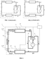
figure 1 shows a heat pump of the prior art in a winter heating mode, -
figure 2 shows the heat pump of the prior art infigure 1 in a summer cooling mode, -
figure 3 shows a heat pump according to an embodiment of the invention in the winter heating mode, -
figure 4 shows the heat pump infigure 3 in the summer cooling mode, -
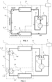
figure 5 shows a heat pump according to a further embodiment of the invention, -
figure 6 shows a heat pump according to a further embodiment of the invention, -
figure 7 shows an expansion valve device of the heat pump infigure 7 according to a further embodiment. - With reference to the figures, a heat pump 1 comprises:
- a
circuit 2 for circulating a refrigerant fluid, - a
first heat exchanger 3 placed in thecircuit 2 and embodying an evaporator 4) in a heating mode of operation and/or acondenser 7 in a cooling mode of operation, - a
compressor 5 placed in thecircuit 2 downstream of thefirst heat exchanger 3, - a
second heat exchanger 6 placed in thecircuit 2 downstream of thecompressor 5 and embodying acondenser 7 in a heating mode of operation and/or anevaporator 4 in a cooling mode of operation, - a
transit duct 10 connecting thesecond heat exchanger 6 to thefirst heat exchanger 3 downstream of thesecond heat exchanger 6, - an
expansion device 8 connected in thetransit duct 10 between thesecond heat exchanger 6 and thefirst heat exchanger 3, - an
electronic control system 9 which controls thecompressor 5 and theexpansion device 8,
where:- the
compressor 5 is operable to suck the refrigerant fluid in the gaseous phase and at low pressure from theevaporator 4, compress the refrigerant fluid, and push it into thecondenser 7, - in the
condenser 7, the compressed refrigerant fluid releases heat and condensates at high pressure, - after leaving the
condenser 7, the refrigerant fluid passes through thetransit duct 10 and theexpansion device 8 which depressurizes it, - the refrigerant fluid depressurized by the
expansion device 8 enters from thetransit duct 10 into theevaporator 4 where it absorbs heat and evaporates at low pressure, before being sucked and compressed again by thecompressor 5.
- the
- The
expansion device 8 comprises a first expansion valve unit 8' and a secondexpansion valve unit 8" arranged in series in thetransit duct 10. - The first expansion valve unit 8' is arranged (in a first end portion of the transit duct 10) at the
first heat exchanger 3 and the secondexpansion valve unit 8" is arranged (in a second end portion of the transit duct 10) at thesecond heat exchanger 6. In an advantageous embodiment: - said first end portion of the
transit duct 10 in which the first expansion valve unit 8' is arranged has a first end length less than 10%, preferably less than 5%, more preferably less than 2%, of a total length of thetransit duct 10, and - said second end portion of the
transit duct 10 in which the secondexpansion valve unit 8" is arranged has a second end length less than 10%, preferably less than 5%, more preferably less than 2%, of the total length of thetransit duct 10. - The
control system 9 and theexpansion device 8 are configured so that: - an (the) evaporator side expansion valve unit 8'; 8" of said first 8' and second 8" expansion valve units is completely open to allow an unthrottled passage of the refrigerant fluid from the
transit duct 10 into theevaporator 4, whereas - a (the) condenser side expansion valve unit 8'; 8" of said first 8' and second 8" expansion valve units is adjusted to act as a single expansion valve to expand the refrigerant fluid when entering from the
condenser 7 into thetransit duct 10. - According to an embodiment, the
compressor 5 is connected in thecircuit 2 by the interposition of a (four-way) switching/invertingvalve 12 controlled by thecontrol system 9 and which allows inverting the compression and circulation direction of the refrigerant fluid and thus switching thefirst heat exchanger 3 from evaporator 4 (in the heating mode of operation) to condenser 7 (in the cooling mode of operation) and switching thesecond heat exchanger 6 from condenser 7 (in the heating mode of operation) to evaporator 4 (in the cooling mode of operation), allowing both cooling and heating of the air or fluid in contact with thefirst heat exchanger 3 and the second heat exchanger 6 (or the environments in which they are located). As described above and illustrated infigures 3 and4 , also when inverting the compression and circulation direction of the refrigerant fluid, i.e. in both the heating mode of operation and the cooling mode of operation, the evaporator side expansion valve unit 8'; 8" of said first 8' and second 8" expansion valve units is completely open to allow an unthrottled passage of the refrigerant fluid from thetransit duct 10 into theevaporator 4, whereas the condenser side expansion valve unit 8'; 8" of said first 8' and second 8" expansion valve units is adjusted to act as a single expansion valve to expand the refrigerant fluid when entering from thecondenser 7 into thetransit duct 10. - According to an embodiment, the heat pump 1 comprises an
external unit 14 intended to be positioned outdoors, (outside a building), aninternal unit 15 intended to be positioned inside a building and connected to a use (device) 35, such as a heating/cooling system with aprimary water circuit 16, for example. Theexternal unit 14 houses in a housing thereof (or through a support structure thereof) at least thefirst heat exchanger 3, and theinternal unit 15 houses in a housing thereof (or through a support structure thereof) at least thesecond heat exchanger 6, where thetransit duct 10 extends between theexternal unit 14 and theinternal unit 15 and the first expansion valve unit 8' is arranged in or at the (housing of) theexternal unit 14 and the secondexpansion valve unit 8" is arranged in or at the (housing of) theinternal unit 15. - According to an embodiment, the first expansion valve unit 8' comprises a first expansion valve 11' controlled by the
control system 9 and adapted to carry out an expansion or lamination of the refrigerant fluid, as well as afirst bypass valve 11a', placed in a first bypass duct 37' which bypasses the first expansion valve 11', and configured or controlled to completely open and close the first bypass duct 37' depending on the flow direction of the refrigerant fluid through the first expansion valve unit 8'. - In particular, the
first bypass valve 11a' closes the first bypass duct 37' when the refrigerant fluid flows through thetransit duct 10 from thefirst heat exchanger 3 towards thesecond heat exchanger 6, and opens the first bypass duct 37' when the refrigerant fluid flows through thetransit duct 10 from thesecond heat exchanger 6 towards thefirst heat exchanger 3. - The
first bypass valve 11a' can be an electric valve actively controlled by theelectronic control system 9 or, advantageously, a self-regulating one-way valve (non-return valve) without any control signal connection with thecontrol system 9. - Similarly, according to an embodiment, the second
expansion valve unit 8" comprises asecond expansion valve 11" controlled by thecontrol system 9 and adapted to carry out an expansion or lamination of the refrigerant fluid, as well as asecond bypass valve 11a", placed in asecond bypass duct 37" which bypasses thesecond expansion valve 11", and configured or controlled to completely open and close thesecond bypass duct 37" depending on the flow direction of the refrigerant fluid through the secondexpansion valve unit 8". - In particular, the
second bypass valve 11a" closes thesecond bypass duct 37" when the refrigerant fluid flows through thetransit duct 10 from thesecond heat exchanger 6 towards thefirst heat exchanger 3, and opens thesecond bypass duct 37" when the refrigerant fluid flows through thetransit duct 10 from thefirst heat exchanger 3 towards thesecond heat exchanger 6. - The
second bypass valve 11a" can be an electric valve actively controlled by theelectronic control system 9 or, advantageously, a self-regulating one-way valve (non-return valve) without any control signal connection with thecontrol system 9. This considerably simplifies the control, the hydraulic structure and the cost of theexpansion device 8. - The heat pump 1 further comprises, in a known manner, a refrigerant fluid storage vessel/
reservoir 13, connected to thecircuit 2, e.g., between the first heat exchanger 3 (e.g., external unit) and thecompressor 5, or directly upstream of thecompressor 5. -
Figure 6 shows a further embodiment of the heat pump 1, with anexternal unit 14 intended to be positioned outdoors, aninternal unit 15 intended to be positioned inside a building, and with a use (device) 35, such as a heating/cooling system with aprimary water circuit 16, for example. - The
external unit 14 comprises (inside a housing): - the
first heat exchanger 3, possibly provided with anair fan 17, an externalair temperature sensor 18, possibly a thermal probe 19' for measuring the temperature of the refrigerant at an intermediate point in thefirst heat exchanger 3, and atemperature sensor 19 for the refrigerant fluid between thefirst heat exchanger 3 and theexpansion device 8, - the
compressor 5 with atemperature sensor 20 for the refrigerant fluid on the suction side of thecompressor 5, and with atemperature sensor 21 for the refrigerant fluid on the delivery side of thecompressor 5 - the refrigerant
fluid storage vessel 13 arranged on the suction side of thecompressor 5, - a
pressure switch 22 arranged on the delivery side of thecompressor 5, - the switching/inverting
valve 12, - (connection attachments of)
tubes 23 of thecircuit 2, - the
expansion device 8 with the first electric expansion valve 11' and the secondelectric expansion valve 11", - a
refrigerant temperature sensor 24 placed in thecircuit 2 between theexpansion device 8 and thesecond heat exchanger 6. - The
internal unit 15 comprises (inside a housing): - the
second heat exchanger 6 which exchanges heat between therefrigerant fluid circuit 2 and theprimary water circuit 16, - a
water pump 25 in theprimary water circuit 16 upstream of thesecond heat exchanger 6, - a flow rate sensor (flowmeter) 26, e.g., on the inlet side of the
water pump 25, - a water
return temperature sensor 27, e.g., on the inlet side of thewater pump 25, - an
expansion vessel 28 of the water connected to theprimary water circuit 16, e.g., on the inlet side of thewater pump 25, - a
water filter 29 connected to theprimary water circuit 16, e.g., upstream of thewater pump 25 and/or upstream of thewater expansion vessel 28, - a water delivery temperature sensor 30 (LWT = Leaving Water Temperature) at the outlet of the
second heat exchanger 6, - an
electric backup heater 31 connected in theprimary water circuit 16, preferably downstream of thesecond heat exchanger 6, to an associatedtemperature sensor 32, for the water at the outlet of theelectric backup heater 31, and - (connection attachments of)
tubes 33 of thecircuit 2, and - (connection attachments of)
tubes 34 of the primary water circuit. - The use (device) 35 comprises a part of the
primary water circuit 16 and awater vessel 36 and/or a plurality of heaters orradiators 36 for heating and cooling. - The invention is also directed to a method of controlling a heat pump, such as the heat pump 1, comprising the steps of:
- A) operating the
compressor 5 to suck the refrigerant fluid in the gaseous phase and at low pressure from theevaporator 4, compress the refrigerant fluid, and push it into thecondenser 7, so that:- in the
condenser 7, the compressed refrigerant fluid releases heat and condensates at high pressure, - after leaving the
condenser 7, the refrigerant fluid passes through thetransit duct 10 and theexpansion device 8 which depressurizes it, - the refrigerant fluid depressurized by the
expansion device 8 enters from thetransit duct 10 into theevaporator 4 where it absorbs heat and evaporates at low pressure, before being sucked and compressed again by thecompressor 5,
- in the
- B) using a switching/inverting
valve 12 to invert a compression and circulation direction of the refrigerant fluid and therefore a switching of thefirst heat exchanger 3 fromevaporator 4 tocondenser 7 and of thesecond heat exchanger 6 fromcondenser 7 toevaporator 4, - C) arranging a first expansion valve unit 8' and a second
expansion valve unit 8" in series in thetransit duct 10, where the first expansion valve unit 8' is arranged (in an end portion of the transit duct 10) at thefirst heat exchanger 3 and the secondexpansion valve unit 8" is arranged (in a second end portion of the transit duct 10) at thesecond heat exchanger 6, - D) controlling the first expansion valve unit 8' and the second
expansion valve unit 8" so that:- an expansion valve unit 8'; 8" on the evaporator side of said first 8' and second 8" expansion valve units is completely open to allow an unthrottled passage of the refrigerant fluid from the
transit duct 10 into theevaporator 4, whereas - an expansion valve unit 8'; 8" on the condenser side of said first 8' and second 8" expansion valve units is adjusted to expand the refrigerant fluid when entering from the
condenser 7 into thetransit duct 10.
- an expansion valve unit 8'; 8" on the evaporator side of said first 8' and second 8" expansion valve units is completely open to allow an unthrottled passage of the refrigerant fluid from the
- The further steps and features of the method correspond to the functions and measures of provision, positioning, structuring and control of the components of the heat pump 1 (understood herein as method steps) already described with reference to the heat pump 1 and not repeated here for conciseness.
-
- heat pump 1
-
circuit 2 -
first heat exchanger 3 -
evaporator 4 -
compressor 5 -
second heat exchanger 6 -
condenser 7 -
expansion device 8 - first expansion valve unit 8'
- second
expansion valve unit 8" -
electronic control system 9 -
transit duct 10 - first expansion valve 11'
-
second expansion valve 11" -
first bypass valve 11a' -
second bypass valve 11a" - switching/inverting
valve 12 -
storage vessel 13 -
external unit 14 -
internal unit 15 -
primary water circuit 16 -
air fan 17 - outdoor
air temperature sensor 18 - thermal probe 19' for the refrigerant fluid in the first heat exchanger
-
temperature sensor 19 for the refrigerant fluid at the first heat exchanger, -
temperature sensor 20 for the refrigerant fluid on the suction side ofcompressor 5 -
temperature sensor 21 for the refrigerant fluid on the delivery side ofcompressor 5 - high pressure switch (pressure switch) 22
- (connection attachments of)
tubes 23 of therefrigerant circuit 2 -
refrigerant temperature sensor 24 -
water pump 25 - water
flow rate sensor 26 -
water temperature sensor 27 -
water expansion vessel 28 -
water filter 29 - water
delivery temperature sensor 30 -
electric backup heater 31 -
temperature sensor 32 for the water at the outlet of the electric heater - (connection attachments of the)
tubes 33 of therefrigerant circuit 2 - (connection attachments of the)
tubes 34 of the primary water circuit - use (device) 35
- radiators/water vessels/
fan coil units 36 - first bypass duct 37'
-
second bypass duct 37"
The first expansion valve unit 8' embodies an evaporator side expansion valve unit in the heating mode of operation and/or a condenser side expansion valve unit in the cooling mode of operation. The second
Claims (12)
- A heat pump (1) comprising:- a circuit (2) for circulating a refrigerant fluid,- a first heat exchanger (3) placed in the circuit (2) and embodying an evaporator (4) in a heating mode of operation and/or a condenser (7) in a cooling mode of operation,- a compressor (5) placed in the circuit (2) downstream of the first heat exchanger (3),- a second heat exchanger (6) placed in the circuit (2) downstream of the compressor (5) and embodying a condenser (7) in a heating mode of operation and/or an evaporator (4) in a cooling mode of operation,- a transit duct (10) connecting the second heat exchanger (6) to the first heat exchanger (3) downstream of the second heat exchanger (6),- an expansion device (8) connected in the transit duct (10) between the second heat exchanger (6) and the first heat exchanger (3),- an electronic control system (9) which controls the compressor (5) and the expansion device (8),wherein:- the compressor (5) is operable to suck the refrigerant fluid in the gaseous phase and at low pressure from the evaporator (4), compress the refrigerant fluid, and push it into the condenser (7),- in the condenser (7), the compressed refrigerant fluid releases heat and condensates at high pressure,- after leaving the condenser (7), the refrigerant fluid passes through the transit duct (10) and the expansion device (8) which depressurizes the refrigerant fluid,- the refrigerant fluid depressurized by the expansion device (8) enters from the transit duct (10) into the evaporator (4) where it absorbs heat and evaporates at low pressure, before being sucked and compressed again by the compressor (5),wherein:- the expansion device (8) comprises a first expansion valve unit (8') and a second expansion valve unit (8") arranged in series in the transit duct (10),- the first expansion valve unit (8') is arranged at the first heat exchanger (3) and the second expansion valve unit (8") is arranged at the second heat exchanger (6),the control system (9) and the expansion device (8) are configured so that:- an expansion valve unit (8'; 8") on the evaporator side (4) of said first (8') and second (8") expansion valve units is completely open to allow an unthrottled passage of the refrigerant fluid from the transit duct (10) into the evaporator (4), while- an expansion valve unit (8'; 8") on the condenser side (7) of said first (8') and second (8") expansion valve units is adjusted to expand the refrigerant fluid when entering from the condenser (7) into the transit duct (10).
- A heat pump (1) according to claim 1, wherein the compressor (5) is connected in the circuit (2) by the interposition of a switching valve (12) controlled by the control system (9) and allowing an inversion of the compression and circulation direction of the refrigerant fluid and therefore a switching of the first heat exchanger (3) from evaporator (4) to condenser (7) and a switching of the second heat exchanger (6) from condenser (7) to evaporator (4).
- A heat pump (1) according to claim 1 or 2, comprising an external unit (14) intended to be positioned in the external environment, an internal unit (15) intended to be positioned inside a building and connected to a use device (35), wherein the external unit (14) accommodates in a housing thereof the first heat exchanger (3) and the internal unit (15) accommodates in a housing thereof the second heat exchanger (6),
wherein the transit duct (10) extends between the external unit (14) and the internal unit (15) and the first expansion valve unit (8') is arranged at the external unit (14) and the second expansion valve unit (8") is arranged at the internal unit (15). - A heat pump (1) according to any one of the preceding claims, wherein the first expansion valve unit (8') comprises:- a first expansion valve (11') controlled by the control system (9) and adapted to perform an expansion of the refrigerant fluid, and- a first bypass valve (11a') positioned in a first bypass duct (37') which bypasses the first expansion valve (11'), and configured or controlled to completely open and close the first bypass duct (37') as a function of the flow direction of the refrigerant fluid through the first expansion valve unit (8').
- A heat pump (1) according to claim 4, wherein the first bypass valve (11a') closes the first bypass duct (37') when the refrigerant fluid flows through the transit duct (10) from the first heat exchanger (3) towards the second heat exchanger (6), and opens the first bypass duct (37') when the refrigerant fluid flows through the transit duct (10) from the second heat exchanger (6) towards the first heat exchanger (3).
- A heat pump (1) according to claim 4 or 5, wherein the first bypass valve (11a') is an electric valve actively controlled by the electronic control system (9).
- A heat pump (1) according to one of claims 4 to 6, wherein the first bypass valve (11a') is a one-directional self-regulated valve without command signal connection with the control system (9).
- A heat pump (1) according to any one of the preceding claims, wherein the second expansion valve unit (8") comprises:- a second expansion valve (11") controlled by the control system (9) and adapted to perform an expansion of the refrigerant fluid, and- a second bypass valve (11a") positioned in a second bypass duct (37") which bypasses the second expansion valve (11"), and configured or controlled to completely open and close the second bypass duct (37") as a function of the flow direction of the refrigerant fluid through the second expansion valve unit (8").
- A heat pump (1) according to claim 8, wherein the second bypass valve (11a") closes the second bypass duct (37') when the refrigerant fluid flows through the transit duct (10) from the second heat exchanger (6) towards the first heat exchanger (3), and opens the second bypass duct (37") when the refrigerant fluid flows through the transit duct (10) from the first heat exchanger (3) towards the second heat exchanger (6).
- A heat pump (1) according to claim 7 or 8, wherein the second bypass valve (11a") is an electric valve actively controlled by the electronic control system (9).
- A heat pump (1) according to one of claims 8 to 10, wherein the second bypass valve (11a") is a one-directional self-regulated valve without a command signal connection with the control system (9).
- A method for controlling a heat pump (1) comprising:- a circuit (2) for circulating a refrigerant fluid,- a first heat exchanger (3) placed in the circuit (2) and forming an evaporator (4) in a heating mode of operation and/or a condenser (7) in a cooling mode of operation,- a compressor (5) placed in the circuit (2) downstream of the first heat exchanger (3),- a second heat exchanger (6) placed in the circuit (2) downstream of the compressor (5) and forming a condenser (7) in a heating mode of operation and/or an evaporator (4) in a cooling mode of operation,- a transit duct (10) connecting the second heat exchanger (6) to the first heat exchanger (3) downstream of the second heat exchanger (6),- an expansion device (8) connected in the transit duct (10) between the second heat exchanger (6) and the first heat exchanger (3),the method comprising the steps of:A) operating the compressor (5) to suck the refrigerant fluid in the gaseous phase and at low pressure from the evaporator (4), compress the refrigerant fluid, and push it into the condenser (7), so that:- in the condenser (7), the compressed refrigerant fluid releases heat and condensates at high pressure,- after leaving the condenser (7), the refrigerant fluid passes through the transit duct (10) and the expansion device (8) which depressurizes the refrigerant fluid,- the refrigerant fluid depressurized by the expansion device (8) enters from the transit duct (10) into the evaporator (4) where it absorbs heat and evaporates at low pressure, before being sucked and compressed again by the compressor (5).B) inverting a compression and circulation direction of the refrigerant fluid and, thereby, switching of the first heat exchanger (3) from evaporator (4) to condenser (7) and switching of the second heat exchanger (6) from condenser (7) to evaporator (4),C) arranging a first expansion valve unit (8') and a second expansion valve unit (8") in series in the transit duct (10), wherein the first expansion valve unit (8') is arranged at the first heat exchanger (3) and the second expansion valve unit (8") is arranged at the second heat exchanger (6),D) controlling the first expansion valve unit (8') and the second expansion valve unit (8") so that:- an expansion valve unit (8'; 8") on the evaporator side (4) of said first (8') and second (8") expansion valve units is completely open to allow an unthrottled passage of the refrigerant fluid from the transit duct (10) into the evaporator (4), while- an expansion valve unit (8'; 8") on the condenser side (7) of said first (8') and second (8") expansion valve units is adjusted to expand the refrigerant fluid when entering from the condenser (7) into the transit duct (10).
Applications Claiming Priority (1)
| Application Number | Priority Date | Filing Date | Title |
|---|---|---|---|
| IT102022000022851A IT202200022851A1 (en) | 2022-11-07 | 2022-11-07 | Heat pump with double expansion valve |
Publications (3)
| Publication Number | Publication Date |
|---|---|
| EP4365509A1 true EP4365509A1 (en) | 2024-05-08 |
| EP4365509B1 EP4365509B1 (en) | 2026-02-18 |
| EP4365509C0 EP4365509C0 (en) | 2026-02-18 |
Family
ID=84943470
Family Applications (1)
| Application Number | Title | Priority Date | Filing Date |
|---|---|---|---|
| EP23206956.7A Active EP4365509B1 (en) | 2022-11-07 | 2023-10-31 | Heat pump and associated method of controlling a heat pump |
Country Status (5)
| Country | Link |
|---|---|
| EP (1) | EP4365509B1 (en) |
| CN (1) | CN117989750A (en) |
| ES (1) | ES3066359T3 (en) |
| IT (1) | IT202200022851A1 (en) |
| PL (1) | PL4365509T3 (en) |
Citations (5)
| Publication number | Priority date | Publication date | Assignee | Title |
|---|---|---|---|---|
| JPS57190366U (en) * | 1981-05-28 | 1982-12-02 | ||
| US4688390A (en) * | 1986-05-27 | 1987-08-25 | American Standard Inc. | Refrigerant control for multiple heat exchangers |
| JPH10332212A (en) * | 1997-06-02 | 1998-12-15 | Toshiba Corp | Refrigeration cycle of air conditioner |
| EP2447096A1 (en) * | 2010-10-28 | 2012-05-02 | Robert Bosch GmbH | Heat pump device with de-icing function |
| US20200271357A1 (en) * | 2017-03-24 | 2020-08-27 | Mitsubishi Electric Corporation | Refrigeration cycle apparatus |
-
2022
- 2022-11-07 IT IT102022000022851A patent/IT202200022851A1/en unknown
-
2023
- 2023-10-31 EP EP23206956.7A patent/EP4365509B1/en active Active
- 2023-10-31 ES ES23206956T patent/ES3066359T3/en active Active
- 2023-10-31 PL PL23206956.7T patent/PL4365509T3/en unknown
- 2023-11-06 CN CN202311470001.8A patent/CN117989750A/en active Pending
Patent Citations (5)
| Publication number | Priority date | Publication date | Assignee | Title |
|---|---|---|---|---|
| JPS57190366U (en) * | 1981-05-28 | 1982-12-02 | ||
| US4688390A (en) * | 1986-05-27 | 1987-08-25 | American Standard Inc. | Refrigerant control for multiple heat exchangers |
| JPH10332212A (en) * | 1997-06-02 | 1998-12-15 | Toshiba Corp | Refrigeration cycle of air conditioner |
| EP2447096A1 (en) * | 2010-10-28 | 2012-05-02 | Robert Bosch GmbH | Heat pump device with de-icing function |
| US20200271357A1 (en) * | 2017-03-24 | 2020-08-27 | Mitsubishi Electric Corporation | Refrigeration cycle apparatus |
Also Published As
| Publication number | Publication date |
|---|---|
| EP4365509B1 (en) | 2026-02-18 |
| ES3066359T3 (en) | 2026-05-12 |
| PL4365509T3 (en) | 2026-05-11 |
| CN117989750A (en) | 2024-05-07 |
| IT202200022851A1 (en) | 2024-05-07 |
| EP4365509C0 (en) | 2026-02-18 |
Similar Documents
| Publication | Publication Date | Title |
|---|---|---|
| RU2738989C2 (en) | Improved thawing by reversible cycle in vapor compression refrigeration systems, based on material with phase transition | |
| US8312734B2 (en) | Cascading air-source heat pump | |
| CN102844630B (en) | Air conditioning and hot-water supply composite system | |
| US4336692A (en) | Dual source heat pump | |
| US4308042A (en) | Heat pump with freeze-up prevention | |
| EP2233863B1 (en) | Free cooling refrigeration system | |
| CN101821560B (en) | air conditioner | |
| CN104813123A (en) | Air-conditioning device | |
| US20060218948A1 (en) | Cooling and heating system | |
| EP2489965A1 (en) | Air-conditioning hot-water supply system | |
| EP2489972A1 (en) | Intermediate heat exchanger and air-conditioning hot-water supply system using same | |
| US9016074B2 (en) | Energy exchange system and method | |
| US6668569B1 (en) | Heat pump apparatus | |
| JPH0333984B2 (en) | ||
| WO2021053924A1 (en) | Air conditioner | |
| US20190055932A1 (en) | Thermodynamic boiler with thermal compressor | |
| CN103090471B (en) | Air-conditioner | |
| CN103890501A (en) | Air conditioning device | |
| US9671131B2 (en) | Hydronic air heater | |
| CN113439188A (en) | Air conditioner | |
| US7266959B2 (en) | Cold climate air-source heat pump | |
| EP4365509B1 (en) | Heat pump and associated method of controlling a heat pump | |
| US20240044546A1 (en) | Water-to-water, water source heat pump with domestic hot water heat priority refrigeration circuit | |
| CN110108056A (en) | The regulating device of refrigeration system | |
| KR20210054772A (en) | Air conditioning system including gas furnace |
Legal Events
| Date | Code | Title | Description |
|---|---|---|---|
| PUAI | Public reference made under article 153(3) epc to a published international application that has entered the european phase |
Free format text: ORIGINAL CODE: 0009012 |
|
| STAA | Information on the status of an ep patent application or granted ep patent |
Free format text: STATUS: THE APPLICATION HAS BEEN PUBLISHED |
|
| AK | Designated contracting states |
Kind code of ref document: A1 Designated state(s): AL AT BE BG CH CY CZ DE DK EE ES FI FR GB GR HR HU IE IS IT LI LT LU LV MC ME MK MT NL NO PL PT RO RS SE SI SK SM TR |
|
| STAA | Information on the status of an ep patent application or granted ep patent |
Free format text: STATUS: REQUEST FOR EXAMINATION WAS MADE |
|
| 17P | Request for examination filed |
Effective date: 20241029 |
|
| RBV | Designated contracting states (corrected) |
Designated state(s): AL AT BE BG CH CY CZ DE DK EE ES FI FR GB GR HR HU IE IS IT LI LT LU LV MC ME MK MT NL NO PL PT RO RS SE SI SK SM TR |
|
| GRAP | Despatch of communication of intention to grant a patent |
Free format text: ORIGINAL CODE: EPIDOSNIGR1 |
|
| STAA | Information on the status of an ep patent application or granted ep patent |
Free format text: STATUS: GRANT OF PATENT IS INTENDED |
|
| RIC1 | Information provided on ipc code assigned before grant |
Ipc: F25B 13/00 20060101AFI20250926BHEP Ipc: F25B 41/20 20210101ALI20250926BHEP Ipc: F25B 41/31 20210101ALI20250926BHEP Ipc: F25B 41/39 20210101ALI20250926BHEP Ipc: F25B 49/02 20060101ALI20250926BHEP |
|
| INTG | Intention to grant announced |
Effective date: 20251022 |
|
| GRAS | Grant fee paid |
Free format text: ORIGINAL CODE: EPIDOSNIGR3 |
|
| GRAA | (expected) grant |
Free format text: ORIGINAL CODE: 0009210 |
|
| STAA | Information on the status of an ep patent application or granted ep patent |
Free format text: STATUS: THE PATENT HAS BEEN GRANTED |
|
| AK | Designated contracting states |
Kind code of ref document: B1 Designated state(s): AL AT BE BG CH CY CZ DE DK EE ES FI FR GB GR HR HU IE IS IT LI LT LU LV MC ME MK MT NL NO PL PT RO RS SE SI SK SM TR |
|
| REG | Reference to a national code |
Ref country code: CH Ref legal event code: F10 Free format text: ST27 STATUS EVENT CODE: U-0-0-F10-F00 (AS PROVIDED BY THE NATIONAL OFFICE) Effective date: 20260218 Ref country code: GB Ref legal event code: FG4D |
|
| REG | Reference to a national code |
Ref country code: IE Ref legal event code: FG4D |
|
| REG | Reference to a national code |
Ref country code: DE Ref legal event code: R096 Ref document number: 602023012161 Country of ref document: DE |
|
| REG | Reference to a national code |
Ref country code: CH Ref legal event code: R17 Free format text: ST27 STATUS EVENT CODE: U-0-0-R10-R17 (AS PROVIDED BY THE NATIONAL OFFICE) Effective date: 20260316 |
|
| U01 | Request for unitary effect filed |
Effective date: 20260226 |
|
| U07 | Unitary effect registered |
Designated state(s): AT BE BG DE DK EE FI FR IT LT LU LV MT NL PT RO SE SI Effective date: 20260304 |
|
| REG | Reference to a national code |
Ref country code: ES Ref legal event code: FG2A Ref document number: 3066359 Country of ref document: ES Kind code of ref document: T3 Effective date: 20260512 |