EP4365499A1 - Outdoor unit for refrigeration cycle device - Google Patents
Outdoor unit for refrigeration cycle device Download PDFInfo
- Publication number
- EP4365499A1 EP4365499A1 EP21948438.3A EP21948438A EP4365499A1 EP 4365499 A1 EP4365499 A1 EP 4365499A1 EP 21948438 A EP21948438 A EP 21948438A EP 4365499 A1 EP4365499 A1 EP 4365499A1
- Authority
- EP
- European Patent Office
- Prior art keywords
- plate
- electric component
- component box
- outdoor unit
- refrigeration cycle
- Prior art date
- Legal status (The legal status is an assumption and is not a legal conclusion. Google has not performed a legal analysis and makes no representation as to the accuracy of the status listed.)
- Granted
Links
Images














Classifications
-
- F—MECHANICAL ENGINEERING; LIGHTING; HEATING; WEAPONS; BLASTING
- F24—HEATING; RANGES; VENTILATING
- F24F—AIR-CONDITIONING; AIR-HUMIDIFICATION; VENTILATION; USE OF AIR CURRENTS FOR SCREENING
- F24F1/00—Room units for air-conditioning, e.g. separate or self-contained units or units receiving primary air from a central station
- F24F1/06—Separate outdoor units, e.g. outdoor unit to be linked to a separate room comprising a compressor and a heat exchanger
- F24F1/20—Electric components for separate outdoor units
- F24F1/24—Cooling of electric components
-
- F—MECHANICAL ENGINEERING; LIGHTING; HEATING; WEAPONS; BLASTING
- F24—HEATING; RANGES; VENTILATING
- F24F—AIR-CONDITIONING; AIR-HUMIDIFICATION; VENTILATION; USE OF AIR CURRENTS FOR SCREENING
- F24F1/00—Room units for air-conditioning, e.g. separate or self-contained units or units receiving primary air from a central station
- F24F1/06—Separate outdoor units, e.g. outdoor unit to be linked to a separate room comprising a compressor and a heat exchanger
- F24F1/20—Electric components for separate outdoor units
- F24F1/22—Arrangement or mounting thereof
-
- F—MECHANICAL ENGINEERING; LIGHTING; HEATING; WEAPONS; BLASTING
- F24—HEATING; RANGES; VENTILATING
- F24F—AIR-CONDITIONING; AIR-HUMIDIFICATION; VENTILATION; USE OF AIR CURRENTS FOR SCREENING
- F24F1/00—Room units for air-conditioning, e.g. separate or self-contained units or units receiving primary air from a central station
- F24F1/06—Separate outdoor units, e.g. outdoor unit to be linked to a separate room comprising a compressor and a heat exchanger
- F24F1/46—Component arrangements in separate outdoor units
-
- F—MECHANICAL ENGINEERING; LIGHTING; HEATING; WEAPONS; BLASTING
- F24—HEATING; RANGES; VENTILATING
- F24F—AIR-CONDITIONING; AIR-HUMIDIFICATION; VENTILATION; USE OF AIR CURRENTS FOR SCREENING
- F24F1/00—Room units for air-conditioning, e.g. separate or self-contained units or units receiving primary air from a central station
- F24F1/06—Separate outdoor units, e.g. outdoor unit to be linked to a separate room comprising a compressor and a heat exchanger
- F24F1/20—Electric components for separate outdoor units
-
- F—MECHANICAL ENGINEERING; LIGHTING; HEATING; WEAPONS; BLASTING
- F24—HEATING; RANGES; VENTILATING
- F24F—AIR-CONDITIONING; AIR-HUMIDIFICATION; VENTILATION; USE OF AIR CURRENTS FOR SCREENING
- F24F1/00—Room units for air-conditioning, e.g. separate or self-contained units or units receiving primary air from a central station
- F24F1/06—Separate outdoor units, e.g. outdoor unit to be linked to a separate room comprising a compressor and a heat exchanger
- F24F1/46—Component arrangements in separate outdoor units
- F24F1/48—Component arrangements in separate outdoor units characterised by air airflow, e.g. inlet or outlet airflow
- F24F1/54—Inlet and outlet arranged on opposite sides
Definitions
- the present disclosure relates to an outdoor unit for a refrigeration cycle apparatus including an electric component box.
- Patent Literature 1 discloses an outdoor unit including an electric component box that houses a control board or electric components. The electric component box is disposed in a space between an air-sending device in an air-sending device chamber and a top panel and above the air-sending device.
- the electric component box of Patent Literature 1 is inclined downward toward an air outlet and upward toward a heat exchanger in a direction of a rotation axis of an air-sending fan, and a heat sink having heat dissipation fins projecting outward is attached to the electric component box. That is, the electric component box of Patent Literature 1 is disposed with inclination such that an upstream side of an airflow is above a downstream side of the airflow. Therefore, the airflow having passed through the heat exchanger and through the heat sink is smoothly guided to the air outlet to have a sufficient air speed for cooling of the heat sink.
- Patent Literature 1 Japanese Unexamined Patent Application Publication No. 2015-215149
- the length of each side of the cuboid electric component box needs to be increased to increase the area of a region including the control board or the electric components without increasing the lateral width of the electric component box.
- the cuboid electric component box increased in the length of each side is disposed with inclination such that the upstream side of the airflow is above the downstream side of the airflow, however, the vertical width of the electric component box, in other words, the height of the electric component box also increases in a projection area of the electric component box projected to a plane orthogonal to the airflow. Therefore, the electric component box does not fit in the space above the air-sending device.
- the projection area of the electric component box projected to the plane orthogonal to the airflow is a projection area of the electric component box viewed from the front of the outdoor unit.
- the present disclosure has been made to solve the problem described above and has an object to provide an outdoor unit for a refrigeration cycle apparatus in which an electric component box having an increased area for disposition of control components can be disposed above an air-sending device without an increase in the vertical width of the electric component box.
- An outdoor unit for a refrigeration cycle apparatus includes a casing that is an outer shell, an air-sending device housed in the casing and configured to generate an airflow, and an electric component box housed in the casing, disposed above the air-sending device, and including a bottom plate on which control components are placed.
- the bottom plate of the electric component box includes an inclined portion on which a first component among the control components is placed.
- the inclined portion is inclined such that an upstream end of the inclined portion on an upstream side of the airflow is positioned above a downstream end of the inclined portion on a downstream side of the airflow.
- the bottom plate further includes a horizontal portion on which a second component among the control components is placed.
- the horizontal portion horizontally extends to the downstream side of the airflow and has an upstream end on the upstream side of the airflow that is connected to the downstream end of the inclined portion on the downstream side of the airflow.
- the bottom plate of the electric component box includes the inclined portion of which the upstream side in the airflow is positioned above the downstream side in the airflow, and the horizontal portion horizontally extending from the inclined portion. Therefore, it is possible to provide the outdoor unit for the refrigeration cycle apparatus in which the electric component box having an increased area for disposition of the control components can be disposed above the air-sending device without the increase in the vertical width of the electric component box.
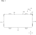
- Fig. 1 is a top view of the appearance of the outdoor unit 100 of the refrigeration cycle apparatus according to Embodiment.
- Fig. 2 is a front view of the appearance of the outdoor unit 100 of the refrigeration cycle apparatus according to Embodiment.
- Fig. 3 is a right side view of the appearance of the outdoor unit 100 of the refrigeration cycle apparatus according to Embodiment.
- Fig. 4 is a left side view of the appearance of the outdoor unit 100 of the refrigeration cycle apparatus according to Embodiment.
- Examples of the refrigeration cycle apparatus include an air-conditioning apparatus.
- the outdoor unit 100 of the refrigeration cycle apparatus includes a casing 100a, which is an outer shell of the outdoor unit 100.
- the casing 100a includes a front panel 104, a left panel 105, a right panel 106, a rear panel 107, a top panel 108, and a bottom panel 109.
- the front panel 104 serves as the front surface of the outdoor unit 100.
- the front panel 104 has an air outlet 104a.
- An air-sending device 2 faces the air outlet 104a.
- a fan guard 104b which covers the air outlet 104a from the outside, is attached to the front panel 104.
- the left panel 105 serves as the left surface of the outdoor unit 100.
- the left panel 105 has an air inlet 105a through which outside air enters the casing 100a.
- the rear panel 107 serves as a right part of the rear surface of the outdoor unit 100 and a rear part of the right surface of the outdoor unit 100. That is, the rear panel 107 has an L-shape in top view.
- the right panel 106 serves as a front part of the right surface of the outdoor unit 100.
- the right panel 106 may be, for example, a service panel detachable at its lower part.
- the left panel 105 and the right panel 106 may have, for example, handles to be held by hands when the outdoor unit 100 is carried.
- the top panel 108 is placed on the front panel 104, the left panel 105, the right panel 106, and the rear panel 107.
- the bottom panel 109 faces the top panel 108 and is disposed parallel to the top panel 108.
- the front panel 104, the left panel 105, the right panel 106, and the rear panel 107 are fixed to the bottom panel 109.
- Fig. 5 is a top view of the internal structure of the outdoor unit 100 of the refrigeration cycle apparatus according to Embodiment.
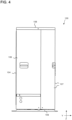
- Fig. 6 is a front view of the internal structure of the outdoor unit 100 of the refrigeration cycle apparatus according to Embodiment, and is a schematic diagram illustrating the inside of the outdoor unit 100.
- Fig. 7 is a side view of the internal structure of the outdoor unit 100 of the refrigeration cycle apparatus according to Embodiment, and is a schematic diagram illustrating the inside of the outdoor unit 100 when a plane along the line BB in Fig. 5 is viewed in a direction of arrows.
- Fig. 5 is a top view of the internal structure of the outdoor unit 100 of the refrigeration cycle apparatus according to Embodiment.
- Fig. 6 is a front view of the internal structure of the outdoor unit 100 of the refrigeration cycle apparatus according to Embodiment, and is a schematic diagram illustrating the inside of the outdoor unit 100.
- Fig. 7 is a side view of the internal structure of the outdoor unit 100 of the refrigeration
- FIG. 8 is a rear view of the internal structure of the outdoor unit 100 of the refrigeration cycle apparatus according to Embodiment, and is a schematic diagram illustrating the inside of the outdoor unit 100 when a plane along the line AA in Fig. 5 is viewed in a direction of arrows.
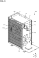
- Fig. 9 is a perspective view illustrating the internal structure of the outdoor unit 100 of the refrigeration cycle apparatus according to Embodiment.
- the casing 100a of the outdoor unit 100 is partitioned into a machine chamber 101 and an air-sending device chamber 102 in a lateral direction.
- a compressor 1 is disposed in the machine chamber 101.
- the air-sending device 2, a heat exchanger 3, and an electric component box 4 are disposed in the air-sending device chamber 102.
- the inside of the casing 100a is partitioned into the machine chamber 101 and the air-sending device chamber 102 by a partition plate 103 disposed on the top of the bottom panel 109 and a first side plate 43 serving as the side surface of the electric component box 4 that faces the machine chamber 101.
- the electric component box 4 is positioned above the partition plate 103.
- the first side plate 43 is described later in detail.
- the compressor 1 housed in the machine chamber 101 is, for example, a compressor capable of controlling the capacity by inverter control drive, and compresses sucked refrigerant into high-temperature and high-pressure gas refrigerant and discharges the refrigerant.
- refrigerant pipes, an expansion valve, and other devices included in a refrigeration cycle are also housed in the machine chamber 101, illustration of these devices is omitted herein.
- the air-sending device 2 housed in the air-sending device chamber 102 includes a propeller fan 2a and a motor 2b.
- the motor 2b of the air-sending device 2 is fixed to a motor support 2c, which extends upward from the bottom panel 109, and is positioned behind the air-sending device 2.
- the air-sending device 2 generates an airflow F so that heat is exchanged efficiently.
- the axis of the air-sending device 2 is along a front-and-rear direction of the casing 100a.
- the air-sending device 2 guides air from the outside (outside air) into the air-sending device chamber 102 and sends the air forward from the outdoor unit 100.
- the air sent by the air-sending device 2 passes through a bell mouth 104c of the front panel 104 and is discharged to the outside of the casing 100a through the air outlet 104a.
- the heat exchanger 3 exchanges heat between the outside air and the refrigerant, and serves as an evaporator during a heating operation and as a condenser during a cooling operation.
- the heat exchanger 3 includes, for example, unillustrated heat transfer tubes through which the refrigerant passes, and unillustrated heat dissipation fins that increase the heat transfer area between the refrigerant in the heat transfer tubes and the outside air.
- the heat exchanger 3 has, for example, an L-shape with a flat region including a long part and a short part and a curved region connecting the long part and the short part.
- the long part of the flat region is disposed at the rear of the air-sending device chamber 102, and the short part of the flat region is disposed at the side of the air-sending device chamber 102 opposite to the machine chamber 101.
- the heat exchanger 3 serves as a part of the rear surface of the casing 100a.
- the heat exchanger 3 may serve as a left surface of the casing 100a. In this case, the casing 100a does not have to have the left panel 105.
- the heat exchanger 3 may have an I-shape in top view with only the long part of the flat region or a U-shape in top view with two curved regions.
- the air-sending device 2 is driven, the outside air is guided into the air-sending device chamber 102 of the outdoor unit 100 and passes through the heat exchanger 3 at this time.
- the electric component box 4 is disposed above the air-sending device 2.
- the electric component box 4 is disposed between the air-sending device 2 and the top panel 108.
- the phrase "above the air-sending device 2" refers to a space between the air-sending device 2 and the top panel 108, and more specifically, a space between the propeller fan 2a and the top panel 108.
- the electric component box 4 is disposed such that the electric component box 4 faces an upper part of the heat exchanger 3 in a horizontal direction.
- a heat sink 430 projects from the electric component box 4. The air guided into the outdoor unit 100 by the drive of the air-sending device 2 passes through the heat sink 430. The heat sink 430 transfers heat to the air guided into the air-sending device chamber 102.
- the electric component box 4 and the upper part of the heat exchanger 3 maintain, in top view, a predetermined distance D1 from each other.
- the distance D1 is a distance at which the airflow F is not obstructed.
- the electric component box 4 and the upper part of the heat exchanger 3 maintain the predetermined distance D1 from each other.
- the predetermined distance D1 is, for example, larger than the thickness of the heat exchanger 3.
- the predetermined distance D1 is, for example, 50 mm.
- the electric component box 4 is disposed at a distance larger than or equal to the predetermined distance D1 at which the airflow F is not obstructed. Therefore, there is no such case that the airflow F does not pass through the upper part of the heat exchanger 3, which faces the electric component box 4. Thus, a decrease in the heat exchange capacity due to the presence of the electric component box 4 can be prevented or reduced.
- the electric component box 4 houses control components that control operations of the outdoor unit 100 including an operation of the compressor 1 or the air-sending device 2.
- the control components include a heat generating component.
- Examples of the control components include a controller formed by hardware such as a circuit device that implements a function to control the operations of the outdoor unit 100, software to be executed on an arithmetic device such as a microcomputer and a central processing unit, or a combination of hardware and software.
- the electric component box 4 has electric wire passing ports 43e (see Fig. 9 ). By electric wires 4b extending through the electric wire passing ports 43e, the control components in the electric component box 4 are connected to constituent elements such as the compressor 1 housed in the machine chamber 101.
- the electric component box 4 houses a control component that may be a cause of firing.
- a control component that may be a cause of firing.
- the refrigerant may leak in the machine chamber 101 including a plurality of connection portions of the refrigerant pipes compared with the air-sending device chamber 102.
- the electric component box 4 is disposed in the air-sending device chamber 102 and separated from the machine chamber 101 by the partition plate 103. Since the refrigerant gas has a greater specific gravity than air, the refrigerant gas that leaks in the machine chamber 101 flows downward in the machine chamber 101. However, the electric component box 4 is disposed above the air-sending device chamber 102. Therefore, the possibility that refrigerant gas having leaked flows into the electric component box 4 can be reduced.
- nonflammable or flammable refrigerant is used as the refrigerant.
- R290 propane
- the air-conditioning apparatus which is the refrigeration cycle apparatus, performs a heating operation and a cooling operation under control of the controller.
- the refrigerant is compressed into high-temperature and high-pressure gas refrigerant and discharged by the compressor 1 housed in the outdoor unit 100.
- the refrigerant discharged from the compressor 1 flows into the heat exchanger 3, which serves as the condenser, exchanges heat with air passing through the heat exchanger 3 to turn into high-pressure liquid refrigerant, and flows out of the heat exchanger 3.
- the pressure of the high-pressure liquid refrigerant having flowed out of the heat exchanger 3 is reduced by the unillustrated expansion valve so that the refrigerant turns into low-pressure two-phase gas-liquid refrigerant.
- the refrigerant flows into an unillustrated indoor unit from the outdoor unit 100.
- the two-phase gas-liquid refrigerant is evaporated into gas refrigerant by receiving heat from indoor air at a heat exchanger of the indoor unit.
- the refrigerant is sucked into the compressor 1 of the outdoor unit 100 again.
- the refrigerant is compressed into high-temperature and high-pressure gas refrigerant and discharged by the compressor 1.
- the refrigerant flows into the unillustrated indoor unit from the outdoor unit 100, and transfers heat to indoor air at the heat exchanger of the indoor unit to turn into high-pressure liquid refrigerant.
- the pressure of the high-pressure liquid refrigerant is reduced by the unillustrated expansion valve of the outdoor unit 100 so that the refrigerant turns into low-pressure two-phase gas-liquid refrigerant.
- the refrigerant exchanges heat with outside air at the heat exchanger 3, which serves as the evaporator, to turn into low-temperature and low-pressure gas refrigerant.
- the refrigerant is sucked into the compressor 1 again.
- Fig. 10 is a perspective view of the electric component box 4 of the outdoor unit 100 of the refrigeration cycle apparatus according to Embodiment.
- the electric component box 4 includes a bottom plate 40, a front plate 41, a rear plate 42, the first side plate 43, and a second side plate 44.
- the bottom plate 40 includes an inclined portion 410 and a horizontal portion 420.
- the right surface, that is, the second side plate 44 has a pentagonal shape.
- the electric component box 4 is made of a metal sheet component.
- the inclined portion 410 is inclined such that, when the electric component box 4 is attached to the outdoor unit 100, an upstream end 410a on an upstream side of the airflow F (see Fig. 7 ) is positioned above a downstream end 410b on a downstream side of the airflow F. With the bottom plate 40 including the inclined portion 410, the airflow F having passed through the heat exchanger 3 disposed further upstream in the airflow F than the electric component box 4 is smoothly guided to the air outlet 104a disposed further downstream in the airflow F than the electric component box 4.
- an upstream end 420a of the horizontal portion 420 on the upstream side of the airflow F is connected to the downstream end 410b of the inclined portion 410, and the horizontal portion 420 extends horizontally downstream to a downstream end 420b.
- the horizontal portion 420 is disposed such that, when the electric component box 4 is attached to the outdoor unit 100, the height positions of the upstream end 420a on the upstream side of the airflow F and the downstream end 420b on the downstream side of the airflow F are aligned horizontally.
- the horizontal portion 420 is parallel to the bottom panel 109 of the outdoor unit 100.
- the horizontal portion 420 does not have to be strictly horizontal, and the horizontal portion 420 and the bottom panel 109 of the outdoor unit 100 does not have to be strictly parallel to each other.
- the heat sink 430 is disposed on the inclined portion 410.
- the heat sink 430 cools the control components such as the controller housed in the electric component box 4.
- the heat sink 430 includes a base plate 403 and a plurality of fins 404 extending along the airflow F on the base plate 403.
- the plurality of fins 404 of the heat sink 430 projects to the outside of the electric component box 4 through a bottom opening 411 described later in the inclined portion 410.
- the surface area of the bottom plate 40 of the electric component box 4 can be increased while the vertical width of the electric component box 4 is maintained compared with a case where the related-art cuboid electric component box is inclined. Therefore, the area for disposition of the control components is increased in the electric component box 4 compared with the case where the cuboid electric component box is inclined.
- Fig. 11 is a diagram illustrating the internal structure of the electric component box 4 of the outdoor unit 100 of the refrigeration cycle apparatus according to Embodiment.
- the control components housed in the electric component box 4 are, for example, a control board 441, electric components 442, and an electrical board 443, which is different from the control board 441.
- the control board 441 is disposed on the inclined portion 410.
- An electric component 442 may be disposed on the inclined portion 410.
- a plurality of ground terminals 405 may be connected to the inclined portion 410.
- the control board 441 is an example of a first component.
- the electric components 442 or the electrical board 443 different from the control board 441 is disposed on the horizontal portion 420.
- a capacitor can be mounted on the horizontal portion 420 as the electric component 442.
- the electric component 442 to be used with limitation when the electric component 442 is inclined can be disposed on the horizontal portion 420.
- the electric components 442 and the electrical board 443 are placed on a mount component 444 and a connection component 445 (see Fig. 15 ).
- the electric components 442 or the electrical board 443 different from the control board 441 is an example of a second component.
- the vertical width is reduced and the area of the disposition region of the electrical board 443 or the electric components 442 is increased.
- the electric component 442 to be used with limitation when the electric component 442 is inclined can be disposed.
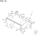
- Fig. 12 is a perspective view of the appearance of the electric component box 4 of the outdoor unit 100 of the refrigeration cycle apparatus according to Embodiment when the right front of the electric component box 4 is viewed from the top.
- Fig. 13 is a perspective view of the appearance of the electric component box 4 of the outdoor unit 100 of the refrigeration cycle apparatus according to Embodiment when the left front of the electric component box 4 is viewed from the top.
- Fig. 14 is a perspective view of the appearance of the electric component box 4 of the outdoor unit 100 of the refrigeration cycle apparatus according to Embodiment when the left rear of the electric component box 4 is viewed from the bottom.
- the outer shell of the electric component box 4 includes the bottom plate 40, the front plate 41, the rear plate 42, the first side plate 43, and the second side plate 44.
- the front plate 41 and the rear plate 42 are parallel to each other and each disposed orthogonally to the first side plate 43 and the second side plate 44.
- the bottom plate 40 includes the inclined portion 410 and the horizontal portion 420.
- the front plate 41 is continuous with the downstream end 420b of the horizontal portion 420 of the bottom plate 40.
- the front plate 41 extends upward from a lower end 41b continuous with the downstream end 410b of the horizontal portion 420 to an upper end 41a.
- the front plate 41 is positioned above the air outlet 104a of the front panel 104. Therefore, the airflow F inside the casing 100a is not obstructed.
- a front support plate 41g extending forward from the front plate 41 is fixed to an upper part of the front plate 41.
- the front support plate 41g has a plurality of lid screw holes 45a.
- a lid 45 described later is attached to the front support plate 41g.
- the rear plate 42 is continuous with the upstream end 410a of the inclined portion 410 of the bottom plate 40.
- the rear plate 42 is disposed parallel to the front plate 41.
- the rear plate 42 extends upward from a lower end 42b continuous with the upstream end 410a of the inclined portion 410 to an upper end 42a.
- a rear support plate 42c extending rearward from the rear plate 42 is fixed to an upper part of the rear plate 42.
- the rear support plate 42c has a plurality of lid screw holes 45a.
- the lid 45 described later is attached to the rear support plate 42c.
- the distance D1 described above is the shortest distance between the heat exchanger 3 and the rear plate 42 without including the rear support plate 42c.
- the first side plate 43 serves as the side surface of the electric component box 4 that faces the machine chamber 101. As illustrated in Fig. 12 , the first side plate 43 has a rectangular shape extending upward from a lower end 43b to an upper end 43a. The first side plate 43 is in contact with the rear plate 42 and the front plate 41.
- a right end 410c of the inclined portion 410 of the bottom plate 40 and a right end 420c of the horizontal portion 420 of the bottom plate 40 are connected to the first side plate 43 along a joint line L.
- the first side plate 43 is partitioned into a body region 431 and a protruding region 432 by the joint line L between the first side plate 43 and the bottom plate 40.
- the protruding region 432 protrudes downward beyond the inclined portion 410 at a boundary that is a part of the first side plate 43 in contact with the right end 410c of the inclined portion 410 of the bottom plate 40.
- the first side plate 43 is attached such that the lower end 43b is in contact with the upper end of the partition plate 103.
- the first side plate 43 together with the partition plate 103 has a function of partitioning the machine chamber 101 and the air-sending device chamber 102.
- the lower end 43b of the first side plate 43 is bent to have a horizontal surface 43g.
- the first side plate 43 is fixed with the horizontal surface 43g of the lower end 43b laid over the horizontal surface of the upper end of the partition plate 103.
- the lower end 43b of the first side plate 43 is attached in contact with the upper end of the partition plate 103, and the first side plate 43 and the partition plate 103 are arranged in the vertical direction but not in the lateral direction.
- the second side plate 44 faces the first side plate 43.
- the second side plate 44 is disposed parallel to the first side plate 43.
- a lower end 44b of the second side plate 44 is continuous with the bottom plate 40.
- the lower end 44b includes an inclined end 44e continuous with the inclined portion 410 of the bottom plate 40, and a horizontal end 44f continuous with the horizontal portion 420 of the bottom plate 40.
- the inclined end 44e is inclined at the same gradient as that of the inclined portion 410.
- the horizontal end 44f horizontally extends at the same height position as that of the horizontal portion 420.
- the second side plate 44 extends upward from the lower end 44b to an upper end 44a.
- An upstream end 44c of the second side plate 44 is continuous with the rear plate 42, and a downstream end 44d of the second side plate 44 is continuous with the front plate 41.
- Fig. 15 illustrates the electric component box 4 of the outdoor unit 100 of the refrigeration cycle apparatus according to Embodiment, and is a schematic diagram illustrating the inside of the electric component box 4 when a plane along the line CC in Fig. 11 is viewed in a +X direction.
- the electrical board 443 is placed on the mount component 444 and fixed to the horizontal portion 420.
- Fig. 16 is a perspective view of the mount component 444 for use in the electric component box 4 of the outdoor unit 100 of the refrigeration cycle apparatus according to Embodiment.
- Fig. 17 is a side view of the mount component 444 for use in the electric component box 4 of the outdoor unit 100 of the refrigeration cycle apparatus according to Embodiment.
- the mount component 444 includes a mount plate 444a extending in a direction parallel to the horizontal portion 420, and a first attachment plate 444b and a second attachment plate 444c extending from the mount plate 444a and fixed to the bottom plate 40.
- the first attachment plate 444b and the second attachment plate 444c are examples of an attachment plate.
- the mount component 444 is made of a metal sheet.
- the mount component 444 is fixed to the bottom plate 40 of the electric component box 4 by, for example, spot welding.
- the mount component 444 is disposed over both the inclined portion 410 and the horizontal portion 420. That is, the first attachment plate 444b extends toward the horizontal portion 420 of the bottom plate 40 from the edge of the mount plate 444a on the downstream side of the airflow F.
- the first attachment plate 444b has an L-shape in side view, and the lower end serves as a fixing plate 444d.
- the first attachment plate 444b is, for example, bent at a right angle.
- the first attachment plate 444b is fixed to the inner surface of the horizontal portion 420 by welding at the fixing plate 444d, which serves as a fixing portion.
- the second attachment plate 444c extends along the inclined portion 410 from the edge of the mount plate 444a on the upstream side of the airflow F.
- the second attachment plate 444c serves as a fixing portion, and is fixed to the inner surface of the inclined portion 410 by welding.
- the mount component 444 Since the mount component 444 is fixed over both the inclined portion 410 and the horizontal portion 420, a horizontal part longer in the front-and-rear direction than the front-and-rear width of the horizontal portion 420 can be secured. Even when the electric component 442 has a dimension larger than the front-and-rear width of the horizontal portion 420, the electric component 442 can be disposed on the planar mount plate 444a parallel to the horizontal portion 420.
- the electric component 442 fixed to the mount component 444 fixed over both the inclined portion 410 and the horizontal portion 420 is included in the electric components 442 disposed on the horizontal portion 420.
- the mount plate 444a has a mount plate screw hole 444f, and the electric component 442 is fixed with a mount screw 444e.
- the mount screw 444e passes through the mount plate screw hole 444f in the mount plate 444a toward the bottom plate 40 of the electric component box 4.
- the tip of the mount screw 444e is received in a space between the mount plate 444a to which the electric component 442 is fixed and the bottom plate 40 of the electric component box 4.
- Fig. 18 is a schematic diagram of a mount component 444 according to Modification 1 of the outdoor unit 100 of the refrigeration cycle apparatus according to Embodiment.
- the second attachment plate 444c of the mount component 444 according to Modification 1 may extend toward the inclined portion 410 of the bottom plate 40 similarly to the first attachment plate 444b without extending along the inclined portion 410 of the bottom plate 40.
- the tip of the second attachment plate 444c is bent into a fixing plate 444d, but is bent at an acute angle instead of the right angle.
- the height of the mount component 444 (dimension in the vertical direction) can be adjusted by use of the length of the second attachment plate 444c. That is, the height of the space between the mount plate 444a and the bottom plate 40 of the electric component box 4 can be adjusted.
- Fig. 19 is a schematic diagram of a mount component 444 according to Modification 2 of the outdoor unit 100 of the refrigeration cycle apparatus according to Embodiment.
- both the first attachment plate 444b and the second attachment plate 444c of the mount component 444 according to Modification 2 are disposed on the horizontal portion 420. That is, the second attachment plate 444c extends toward the inclined portion 410 of the bottom plate 40 similarly to the first attachment plate 444b without extending along the inclined portion 410 of the bottom plate 40.
- the tip of the second attachment plate 444c is bent at the right angle into a fixing plate 444d similarly to the first attachment plate 444b.
- the first attachment plate 444b and the second attachment plate 444c are provided at the edge of the mount plate 444a on the upstream side of the airflow F and the edge of the mount plate 444a on the downstream side of the airflow F, but may be provided at the edges in the lateral direction intersecting the airflow F.
- the first attachment plate 444b and the second attachment plate 444c may be provided at four sides of the mount plate 444a, that is, at the edges on the upstream side, on the downstream side, and in the lateral direction.
- Fig. 20 illustrates the electric component box 4 of the outdoor unit 100 of the refrigeration cycle apparatus according to Embodiment, and is a schematic diagram illustrating the inside of the electric component box 4 when a plane along the line DD in Fig. 11 is viewed in a -X direction.
- connection component 445 is fixed to the bottom plate 40 and projects to the inside of the electric component box 4 from the inner surface of the inclined portion 410 of the electric component box 4.
- the connection component 445 is made of a metal sheet.
- the connection component 445 has a structure similar to that of the mount component 444.
- Fig. 21 is a perspective view of the connection component 445 for use in the electric component box 4 of the outdoor unit 100 of the refrigeration cycle apparatus according to Embodiment.
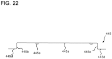
- Fig. 22 is a side view of the connection component 445.
- Fig. 23 is a perspective view illustrating the connection component 445 on which the electric component 442 is mounted.
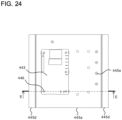
- Fig. 24 is a top view illustrating the connection component 445 on which the electric component 442 is mounted.
- Fig. 25 is a side view illustrating the connection component 445 on which the electric component 442 is mounted.
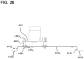
- Fig. 26 is a schematic diagram illustrating the connection component 445 on which the electric component 442 is mounted in the outdoor unit 100 of the refrigeration cycle apparatus according to Embodiment, and is a sectional view along the line EE in Fig. 24 .
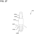
- Fig. 27 is an enlarged view of a fixing part 446 of the outdoor unit 100 of the refrigeration cycle apparatus according to Embodiment.
- the connection component 445 includes a connection plate 445a extending in a direction parallel to the bottom plate 40, a first leg 445b, and a second leg 445c.
- the first leg 445b and the second leg 445c extend from the connection plate 445a and are fixed to the bottom plate 40.
- the connection component 445 is disposed on the inclined portion 410.
- the connection component 445 is fixed to the bottom plate 40 of the electric component box 4 by, for example, spot welding.
- the first leg 445b is provided on the downstream side of the airflow F
- the second leg 445c is provided on the upstream side of the airflow F.
- the electric component 442 and the ground terminals 405 are fixed to the connection component 445.
- the ground terminal 405 is connected to one end of a ground wire.
- the other end of the ground wire is connected to the control board 441.
- the first leg 445b extends toward the inclined portion 410 of the bottom plate 40 from the edge of the connection plate 445a on the downstream side of the airflow F, and the tip is bent at a right angle into a fixing plate 445d.
- the second leg 445c extends toward the inclined portion 410 of the bottom plate 40 similarly to the first leg 445b from the edge of the connection plate 445a on the upstream side of the airflow F, and the tip is bent at a right angle into a fixing plate 445d.
- the fixing plates 445d of the first leg 445b and the second leg 445c are fixed to the inner surface of the inclined portion 410 by welding.
- connection plate 445a has a plurality of fixing holes 445e.
- the electrical board 443 is fixed to the connection plate 445a.
- the fixing parts 446 passing through the electrical board 443 are inserted into the fixing holes 445e to fix the electrical board 443 to the connection plate 445a.
- the ground terminals 405 may be fixed to the connection plate 445a by the fixing parts 446.
- connection component 445 includes the connection plate 445a, the first leg 445b, and the second leg 445c, the bottom plate 40 of the electric component box 4 does not have holes through which the electrical board 443 is fixed to the connection component 445. Therefore, the bottom plate 40 of the electric component box 4 does not have an unsealed part. Thus, refrigerant gas having leaked can be prevented from flowing into the electric component box 4.
- the fixing part 446 is made of a resin. As illustrated in Fig. 27 , the fixing part 446 includes a base portion 446a at one end, a fixing portion 446b at the other end, and a spacer 446c provided between the base portion 446a and the fixing portion 446b.
- the spacer 446c has a flare 446f shaped to flare out toward the fixing portion 446b.
- a first constriction 446d is provided between the base portion 446a and the spacer 446c.
- a second constriction 446e is provided between the spacer 446c and the fixing portion 446b.
- the first constriction 446d is thinner than the base portion 446a and the spacer 446c.
- the second constriction 446e is thinner than the spacer 446c and the fixing portion 446b.
- the fixing part 446 is pushed into a through hole in the electrical board 443 and further into the fixing hole 445e in the connection plate 445a.
- the connection plate 445a is sandwiched between the lower end of the flare 446f of the spacer 446c and the fixing portion 446b, and the electrical board 443 is sandwiched between the base portion 446a and the spacer 446c.
- the electrical board 443 is fixed to the connection component 445 with a distance corresponding to the spacer 446c from the connection plate 445a.
- the electrical board 443 is supported by the connection component 445 such that the fixing part 446 molded from an insulating resin is interposed, the electrical board 443 is kept insulated from the connection component 445 made of the metal sheet and, furthermore, the electric component box 4 made of the metal sheet.
- the fixing portion 446b at the other end of the fixing part 446 is received in a space between the connection plate 445a and the inclined portion 410 of the electric component box 4.
- the ground terminals 405 be fixed to the mount component 444.
- the ground terminals 405 may be fixed to the mount component 444 with the mount screws 444e similarly to the electric component 442 fixed to the mount component 444.
- the ground terminals 405 may be fixed to the mount plate 444a of the mount component 444, or may be fixed to the first attachment plate 444b or the second attachment plate 444c of the mount component 444. In this case as well, a space is secured between the mount plate 444a and the bottom plate 40 of the electric component box 4. Therefore, it is possible to prevent refrigerant gas having leaked from flowing in through an unsealed part generated by the screw for fixation of the ground terminal 405, and the safety in the attachment work for the electric component box 4 from being impaired.
- the mount screw 444e is an example of a ground terminal screw.
- Fig. 28 illustrates the electric component box 4 of the outdoor unit 100 of the refrigeration cycle apparatus according to Embodiment, and is a schematic diagram when a plane along the line JJ in Fig. 11 is viewed in the +X direction.
- Fig. 29 is an exploded perspective view illustrating an attachment structure for the control board 441 of the outdoor unit 100 of the refrigeration cycle apparatus according to Embodiment.
- Fig. 30 is an exploded schematic sectional view of the electric component box 4 of the outdoor unit 100 of the refrigeration cycle apparatus according to Embodiment.
- the control board 441 is disposed on the inclined portion 410 such that the control board 441 is held by a board case 463.
- the board case 463 includes a resin case 463a and a frame-shaped resin holder 463b.
- the control board 441 is held between the resin case 463a and the resin holder 463b such that the control board 441 is fitted to the resin case 463a.
- the resin holder 463b is fixed to the board case 463 with first screws 463c.
- the board case 463 is fixed to the inner surface of the inclined portion 410 of the electric component box 4 with second screws 463d.
- the second screws 463d are attached from the outside of the electric component box 4 to the inside of the electric component box 4 and screwed into the resin case 463a through screw passing holes in the inclined portion 410.
- a first surface 403a of the base plate 403 of the heat sink 430 is attached to the board case 463 with third screws 463e such the first surface 403a is in contact with a heat generating component of the control board 441.
- the first surface 403a of the base plate 403 is opposite to the surface where the plurality of fins 404 projects.
- the base plate 403 of the heat sink 430 closes the bottom opening 411 in the inclined portion 410 from the inside of the electric component box 4.
- the plurality of fins 404 of the heat sink 430 projects through the bottom opening 411. Since the heat sink 430 is fixed to the inclined portion 410, the airflow F is not obstructed and the heat sink 430 is efficiently cooled by the airflow F.
- the electric component 442 and other devices housed in the electric component box 4 may be a cause of firing. Therefore, it is important to employ a structure in which, even when the refrigerant gas leaks, the refrigerant gas having leaked does not flow into the electric component box 4.
- a first sealer 402a is held between the second screws 463d and the inclined portion 410 of the bottom plate 40 of the electric component box 4.
- the second screw 463d is an example of a board case screw.
- a second sealer 402b is held between the inclined portion 410 of the bottom plate 40 of the electric component box 4 and the resin case 463a of the board case 463.
- a third sealer 402c is held between the board case 463 and the heat sink 430. With the third sealer 402c, refrigerant gas having leaked is prevented from flowing through the bottom opening 411 from which the heat sink 430 projects.
- the electric component box 4 houses the control board 441 and the electric component 442, which may be a cause of firing.
- the refrigerant gas it is important to, when the refrigerant gas leaks, eliminate the possibility that the refrigerant gas having leaked flows into the electric component box 4.
- the first sealer 402a, the second sealer 402b, and the third sealer 402c of the electric component box 4 it is possible to eliminate the possibility that refrigerant gas having leaked flows into the electric component box 4 through the bottom opening 411 or the screw passing holes in the inclined portion 410 through which the second screws 463d pass.
- Fig. 31 is a perspective view of an assembling process for the electric component box 4 of the outdoor unit 100 of the refrigeration cycle apparatus according to Embodiment when the left front of the electric component box 4 is viewed from the top.
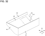
- Fig. 32 is a perspective view of the assembling process for the electric component box 4 of the outdoor unit 100 of the refrigeration cycle apparatus according to Embodiment when the right front of the electric component box 4 is viewed from the top.
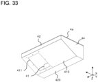
- Fig. 33 is a perspective view of the assembling process for the electric component box 4 of the outdoor unit 100 of the refrigeration cycle apparatus according to Embodiment when the left rear of the electric component box 4 is viewed from the bottom.
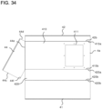
- Fig. 34 is a developed view of the electric component box 4 of the outdoor unit 100 of the refrigeration cycle apparatus according to Embodiment.
- the electric component box 4 is manufactured in such a manner that the first side plate 43 is joined to a box-shaped metal sheet component 4a including the bottom plate 40, the front plate 41, the rear plate 42, and the second side plate 44.
- a metal sheet having a predetermined shape including the bottom plate 40, the front plate 41, the rear plate 42, and the second side plate 44 is first cut.
- the bottom opening 411 is provided by punching.
- Fig. 34 illustrates the metal sheet cut into the predetermined shape. The cut metal sheet is bent at appropriate positions and the seams are welded such that the metal sheet is made into the box-shaped metal sheet component 4a.
- the metal sheet is bent at a bending position between the lower end 42b of the rear plate 42 and the upstream end 410a of the inclined portion 410 of the bottom plate 40 such that an angle ⁇ 1 between the rear plate 42 and the inclined portion 410 of the bottom plate 40 is an obtuse angle.
- the angle ⁇ 1 between the rear plate 42 and the inclined portion 410 of the bottom plate 40 is, for example, 120 degrees.
- the downstream end 410b of the inclined portion 410 of the bottom plate 40 and the upstream end 420a of the horizontal portion 420 of the bottom plate 40 are connected to each other, the ends thus connected serve as a bending position, and the metal sheet is bent such that an angle ⁇ 2 between the horizontal portion 420 and the inclined portion 410 is an obtuse angle.
- the angle ⁇ 2 between the horizontal portion 420 and the inclined portion 410 is, for example, 150 degrees.
- the downstream end 420b of the horizontal portion 420 of the bottom plate 40 and the lower end 43b of the front plate 41 are connected to each other, the ends thus connected serve as a bending position, and the metal sheet is bent such that the horizontal portion 420 of the bottom plate 40 and the front plate 41 have a right angle.
- the lower inclined end 44e of the second side plate 44 is connected to the inclined portion 410, and the connection position serves as a bending position.
- the metal sheet is bent such that the second side plate 44 and the inclined portion 410 have a right angle.
- the horizontal end 44f of the second side plate 44 is welded to the horizontal portion 420 of the bottom plate 40 over the total length.
- the upstream end 44c of the second side plate 44 is welded to the rear plate 42 over the total length.
- the downstream end 44d of the second side plate 44 is welded to the front plate 41 over the total length.
- the electric component box 4 is formed in such a manner that the first side plate 43 is welded to the metal sheet component 4a including the bottom plate 40, the front plate 41, the rear plate 42, and the second side plate 44.
- the first side plate 43 is welded continuously to the front plate 41, the bottom plate 40, and the rear plate 42 over their total lengths.
- Many corners of the electric component box 4 are defined by bending the metal sheet and therefore the number of welded portions is reduced.
- the risk of inflow of refrigerant gas having leaked into the electric component box 4 through an insufficiently welded portion is reduced.
- the second side plate 44 may be provided separately similarly to the first side plate 43.
- the inclined end 44e of the second side plate 44 is not connected to the inclined portion 410, and is welded to the inclined portion 410 over the total length.
- Fig. 35 is a perspective view of the first side plate 43 of the electric component box 4 of the outdoor unit 100 of the refrigeration cycle apparatus according to Embodiment when the first side plate 43 is viewed from the outside of the electric component box 4.
- Fig. 36 is a side view of the first side plate 43.
- the first side plate 43 is made of a metal sheet. As illustrated in Fig. 35 and Fig. 36 , the first side plate 43 has a rectangular shape including the body region 431 and the protruding region 432. In Fig. 35 , the body region 431 is higher than the joint line L, and the protruding region 432 is lower than the joint line L.
- the first side plate 43 has a plurality of electric wire passing ports 43e.
- the lower end 43b of the first side plate 43 has the horizontal surface 43g bent in the horizontal direction.
- the horizontal surface 43g is laid over the horizontal surface of the upper end of the partition plate 103.
- the first side plate 43 is attached to the metal sheet component 4a and therefore the electric component box 4 is manufactured. Specifically, the first side plate 43 is welded to the right end 410c of the inclined portion 410 of the bottom plate 40 and the right end 420c of the horizontal portion 420 of the bottom plate 40 along the joint line L over the total lengths. The first side plate 43 is welded to the rear plate 42 on the upstream side of the airflow F and to the front plate 41 on the downstream side of the airflow F over the total lengths.
- the outer surface of the electric component box 4 made of the metal sheet be subjected to oil coating.
- the electric component box 4 is subjected to resin coating such that the welded portions are covered.
- the inner surface of the electric component box 4 may also be subjected to resin coating, but it is sufficient that at least the outer surface be subjected to resin coating.
- Fig. 37 is a side view illustrating the first side plate 43 of the electric component box 4 of the outdoor unit 100 of the refrigeration cycle apparatus according to Embodiment.
- Fig. 38 is an enlarged view of the electric wire passing ports 43e in the first side plate 43.
- the first side plate 43 has the electric wire passing ports 43e.
- the electric wire passing port 43e is filled with a sealer 43f.
- the electric wire passing port 43e is a hole for passage of the electric wire 4b extending from the electric component 442, the control board 441, or the electrical board 443 in the electric component box 4 to the machine chamber 101.
- the sealer 43f is an elastically deformable part, and seals a region other than the electric wire 4b by being elastically deformed.
- the sealer 43f is made of, for example, rubber.
- the electric wire 4b is connected to, for example, the compressor 1 or another constituent element such as the unillustrated expansion valve.
- the sealer 43f seals the region of the electric wire passing port 43e other than the electric wire 4b. Even when the refrigerant gas leaks in the machine chamber 101, the refrigerant gas having leaked is prevented from flowing into the electric component box 4 through the electric wire passing port 43e.
- the electric wire passing port 43e be provided in the first side plate 43 alone, and the electric wire passing port 43e does not have to be provided in both the electric component box 4 and the partition plate 103. Therefore, the wiring workability is improved.
- Fig. 39 is an exploded perspective view of the electric component box 4 of the outdoor unit 100 of the refrigeration cycle apparatus according to Embodiment.
- Fig. 40 is a perspective view of the lid 45 of the electric component box 4 of the outdoor unit 100 of the refrigeration cycle apparatus according to Embodiment when the lid 45 is viewed obliquely from the top.
- Fig. 41 is a perspective view of the lid 45 of the electric component box 4 of the outdoor unit 100 of the refrigeration cycle apparatus according to Embodiment when the lid 45 is viewed obliquely from the bottom.
- Fig. 42 is an exploded perspective view of the lid 45 of the electric component box 4 of the outdoor unit 100 of the refrigeration cycle apparatus according to Embodiment.
- the top of the electric component box 4 is hermetically closed by being covered with the lid 45.
- the lid 45 is a rectangular part that covers the internal space of the electric component box 4 from the top.
- the lid 45 includes a lid plate 451 and a frame plate 452.
- the lid plate 451 is disposed parallel to the horizontal portion 420 of the bottom plate 40.
- the lid plate 451 has a rectangular shape larger than a rectangular shape defined by the front plate 41, the rear plate 42, the first side plate 43, and the second side plate 44 serving as outer peripheral walls of the electric component box 4.
- a lid sealer 451a is held between the lid plate 451 and the upper ends of the outer peripheral walls of the electric component box 4.
- the lid sealer 451a has the same shape as the rectangular shape defined by the upper ends of the front plate 41, the rear plate 42, the first side plate 43, and the second side plate 44 serving as the outer peripheral walls of the electric component box 4.
- the lid sealer 451a is held by the lid plate 451 such that the lid sealer 451a is placed on a sealer receiving surface 4c defined by the upper ends of the front plate 41, the rear plate 42, the first side plate 43, and the second side plate 44 of the electric component box 4.
- the sealer receiving surface 4c is defined in such a manner that the upper ends of the front plate 41, the rear plate 42, the first side plate 43, and the second side plate 44 are bent to the inside of the electric component box 4.
- the lid sealer 451a is held between the lower surface of the lid plate 451 and the sealer receiving surface 4c at all of the four sides of the electric component box 4, and the lid 45 and the outer peripheral walls of the electric component box 4 are sealed over the entire periphery.
- the frame plate 452 extends downward from the outer periphery of the lid plate 451 to have a right angle with the lid plate 451, and is disposed such that the frame plate 452 covers the tops of the outer peripheral walls of the electric component box 4.
- the frame plate 452 is disposed such that the frame plate 452 faces the upper parts of the front plate 41, the rear plate 42, the first side plate 43, and the second side plate 44.
- the frame plate 452 surrounds the upper parts of the front plate 41, the rear plate 42, the first side plate 43, and the second side plate 44. Therefore, horizontal movement of the lid 45 is restricted.
- a front frame plate 452a of the frame plate 452 which faces the front plate 41, has a front fixing plate 452b bent at a right angle from the lower end of the front frame plate 452a and extending away from the front plate 41.
- the front fixing plate 452b and the rear fixing plate 452d have a plurality of lid screw passing holes 452e along their longitudinal directions.
- the plurality of lid screw passing holes 452e is arranged at regular intervals.
- the lid screw passing holes 452e in the front fixing plate 452b are positioned in alignment with the lid screw holes 45a in the front support plate 41g of the electric component box 4.
- the lid screw passing holes 452e in the rear fixing plate 452d are positioned in alignment with the lid screw holes 45a in the rear support plate 42c of the electric component box 4.
- the front fixing plate 452b of the lid 45 is disposed such that the front fixing plate 452b is laid over the front support plate 41g of the electric component box 4.
- the front fixing plate 452b is fixed to the front support plate 41g in such a manner that lid screws 453f passing through the lid screw passing holes 452e in the front fixing plate 452b are screwed into the lid screw holes 45a in the front support plate 41g.
- the rear fixing plate 452d of the lid 45 is fixed to the rear support plate 42c in such a manner that the lid screws 453f are screwed into the lid screw holes 45a in the rear support plate 42c.
- the front fixing plate 452b have a width enough to be coupled to the front support plate 41g extending from the front plate 41.
- the rear fixing plate 452d have a width enough to be coupled to the rear support plate 42c extending from the rear plate 42.
- the lid 45 is fixed to the electric component box 4 in such a manner that the front fixing plate 452b of the lid 45 is disposed such that the front fixing plate 452b is laid over the front support plate 41g, the rear fixing plate 452d is disposed such that the rear fixing plate 452d is laid over the rear support plate 42c, and the front fixing plate 452b and the rear fixing plate 452d are fixed with the lid screws 453f.
- a self-tapping screw is used as the lid screw 453f, which fixes the lid 45.
- the self-tapping screw is a screw to be screwed into a target material having a pilot hole instead of an internally threaded target material.
- the self-tapping screw is screwed and thus plastically deforms the hole in the target material to form an internal thread. It is sufficient that the hole in the target material be a flanged hole, or be simply a through hole when the target material is thick.
- the lid screw holes 45a in the front support plate 41g and the rear support plate 42c are flanged holes, and the lid screws 453f, which are self-tapping screws, are screwed to form internal threads.
- the top panel 108 of the casing 100a may be used as a lid that covers the internal space of the electric component box 4 from the top.
- the lid 45 can be omitted and therefore the number of components can be reduced.
- Fig. 43 is a schematic side view illustrating a fixing structure for the electric component box 4 of the outdoor unit 100 of the refrigeration cycle apparatus according to Embodiment.
- Fig. 44 is a schematic side view illustrating fixation of the front side of the electric component box 4, and is an enlarged view of the dotted circle G in Fig. 43 .
- Fig. 45 is a schematic side view illustrating fixation of the rear side of the electric component box 4, and is an enlarged view of the dotted circle H in Fig. 43 .
- the electric component box 4 is fixed in the space between the propeller fan 2a in the air-sending device chamber 102 and the top panel 108 in such a manner that the front support plate 41g of the front plate 41 is attached to the front panel 104 and the rear support plate 42c of the rear plate 42 is attached to the motor support 2c.
- a front fixing piece 41h projecting forward is provided at a part of the front support plate 41g to which the front fixing plate 452b of the lid 45 is fixed.
- the tip of the front fixing piece 41h is a front fixing portion 41i bent upward, and the front fixing portion 41i has a fixing screw hole.
- the front fixing piece 41h is provided at a part of the front support plate 41g in the longitudinal direction and, in this case, is provided at the center of the electric component box 4 in the lateral direction.
- the electric component box 4 is fixed to the front panel 104 in such a manner that the front fixing portion 41i is disposed along the inner surface of the front panel 104 and a panel fixing screw 104d passing through a screw passing hole in the front panel 104 is screwed into the fixing screw hole in the front fixing portion 41i.
- the head of the panel fixing screw 104d is positioned on the outside of the front panel 104, but a folded piece at the outer peripheral edge of the top panel 108 is positioned on the outside of the head of the panel fixing screw 104d so that the head of the panel fixing screw 104d is not exposed.
- a part of the rear support plate 42c to which the rear fixing plate 452d of the lid 45 is fixed is sandwiched between the rear fixing plate 452d of the lid 45 and the upper end of the motor support 2c.
- the rear fixing plate 452d of the lid 45 and the rear support plate 42c are fastened together to the upper end of the motor support 2c with the lid screw 453f.
- the electric component box 4 is fixed to the motor support 2c.
- the rear support plate 42c has the plurality of lid screw holes 45a. At the part of the rear support plate 42c that is sandwiched between the rear fixing plate 452d and the upper end of the motor support 2c, a screw passing hole having a larger bore diameter than the lid screw hole 45a and simply passing through the rear support plate 42c is provided instead of the lid screw hole 45a.
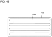
- Fig. 46 is a plan view of the top panel 108 of the outdoor unit 100 of the refrigeration cycle apparatus according to Embodiment.
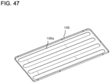
- Fig. 47 is a perspective view of the top panel 108 when the top panel 108 is viewed from the inside.
- cushions 108a are bonded to the inner surface of the top panel 108.
- the cushions 108a may be bonded to the outer surface of the lid 45 of the electric component box 4.
- the cushions 108a are interposed between the top panel 108 made of the metal sheet and the lid 45 of the electric component box 4 made of the metal sheet to prevent contact between the top panel 108 and the lid 45 and to close a gap between the top panel 108 and the lid 45, thereby preventing air having passed through the heat exchanger 3 from flowing between the top panel 108 and the lid 45.
- a plurality of band-shaped cushions 108a be provided along the long side of the rectangular top panel 108 and one or more cushions 108a be in contact with the lid 45 such that the one or more cushions 108a are disposed over the lid 45 in the lateral direction. It is preferable that the cushions 108a be in contact with the end of the lid 45 on the upstream side of the airflow F.
- the cushions 108a may have band shapes and may be disposed along the four edges of the lid 45 in a rectangular shape in plan view. The cushions 108a close the gap between the top panel 108 and the lid 45 of the electric component box 4.
- the bottom plate 40 of the electric component box 4 includes the inclined portion 410 of which the upstream side in the airflow F is positioned above the downstream side in the airflow F, and the horizontal portion 420 extending in the horizontal direction from the downstream side of the inclined portion 410. Therefore, the electric component box 4 having an increased area for disposition of the housed control components can be disposed above the air-sending device 2 without the increase in the vertical height of the projection area of the electric component box 4 in the plane orthogonal to the airflow F.
- the plurality of fins 404 of the heat sink 430 projects through the bottom opening 411 in the inclined portion 410. Therefore, a sufficient volume of air can be obtained for cooling of the heat sink 430.
- the plurality of fins 404 is arranged side by side in the direction orthogonal to the airflow F and parallel to the lateral direction of the casing 100a. Therefore, the cooling efficiency of the heat sink 430 is improved.
- the first sealer 402a is held between the second screws 463d passing through the board case 463 and the bottom plate 40, and the second sealer 402b is held between the board case 463 and the bottom plate 40. Further, the third sealer 402c is held between the board case 463 and the base plate 403 of the heat sink 430. Even when the refrigerant leaks and the refrigerant having leaked flows into the air-sending device chamber 102, the refrigerant gas having leaked is prevented from flowing into the electric component box 4 through the bottom opening 411 from which the heat sink 430 projects, and is prevented from flowing into the electric component box 4 through the screw passing holes of the second screws 463d, which fix the board case 463 through the bottom plate 40.
- the electric component box 4 is disposed at the distance larger than or equal to the distance D1 from the heat exchanger 3 in top view. Therefore, the electric component box 4 does not obstruct the passage of the airflow F through the upper part of the heat exchanger 3, which faces the electric component box 4. Thus, the air passes also through the upper part of the heat exchanger 3.
- the electric component box 4 disposed in the upper part of the air-sending device chamber 102 does not cause a decrease in the heat exchange capacity of the heat exchanger 3.
- the mount component 444 including the mount plate 444a and the first attachment plate 444b and the second attachment plate 444c extending from the mount plate 444a and fixed to the bottom plate 40 of the electric component box 4 is fixed to the bottom plate 40. A space is secured between the mount plate 444a and the bottom plate 40.
- the tip of the mount screw 444e does not project to the outside from the bottom plate 40 of the electric component box 4. Therefore, there is no unsealed part that may be generated by a projecting screw and may be a part through which refrigerant gas having leaked flows in. Further, the safety is maintained in the attachment work for the electric component box 4.
- the mount component 444 is fixed over both the inclined portion 410 and the horizontal portion 420. Therefore, a planar part longer in the front-and-rear direction than the front-and-rear width of the horizontal portion 420 can be secured. Even the electric component 442 having a front-and-rear dimension larger than the front-and-rear width of the horizontal portion 420 can be disposed on the mount plate 444a parallel to the horizontal portion 420.
- the mount component 444 is fixed to the horizontal portion 420, and the tip of the mount screw 444e, which fixes the electric component 442, is received between the mount plate 444a and the horizontal portion 420. Therefore, the tip of the mount screw 444e, which fixes the electric component 442 or the ground terminal 405, does not project to the outside from the bottom plate 40 of the electric component box 4.
- connection component 445 is fixed to the inclined portion 410 of the electric component box 4, and the ground terminals 405 are fixed to the connection component 445 with screws. Therefore, the tips of the screws do not project to the outside from the bottom plate 40 of the electric component box 4. Thus, there is no unsealed part that may be generated by a projecting screw and may be a part through which refrigerant gas having leaked flows in. Further, the safety is maintained in the attachment work for the electric component box 4.
- connection component 445 includes the connection plate 445a, and the first leg 445b and the second leg 445c extending from the connection plate 445a. Therefore, a space is secured between the connection plate 445a and the bottom plate 40. Therefore, when the electric component 442, the electrical board 443, or the ground terminal 405 is fixed to the connection component 445 with a screw, the tip of the screw does not project to the outside from the bottom plate 40 of the electric component box 4.
- connection plate 445a The tip of the fixing part 446, which fixes the electrical board 443, is received in the space between the connection plate 445a and the bottom plate 40 of the electric component box 4. Therefore, the electrical board 443 can be fixed onto the connection plate 445a of the connection component 445 with the fixing part 446 made of a resin in such a manner that the fixing part 446 is inserted into the fixing hole 445e in the connection component 445.
- the electrical board 443 can be kept insulated from the connection component 445 and the electric component box 4 made of the metal sheets.
- the first side plate 43 can function to partition the upper part of the machine chamber 101 and the upper part of the air-sending device chamber 102. Therefore, the amount of use of the plate can be reduced and the resources can be saved compared with the case where only the partition plate 103 partitions the machine chamber 101 and the air-sending device chamber 102 and the partition plate 103 and the first side plate 43 are arranged in the lateral direction.
- the first side plate 43 has the electric wire passing port 43e for passage of the electric wire 4b connecting the device disposed in the machine chamber 101 and the control board 441, the electrical board 443, or the electric component 442 in the electric component box 4. Since the first side plate 43 partitions the upper part of the machine chamber 101 and the upper part of the air-sending device chamber 102, the electric wire 4b simply passes through the electric wire passing port 43e in the first side plate 43, and does not have to further pass through the partition plate 103. Thus, the wiring workability for a worker is improved.
- the sealer 43f is provided in the electric wire passing port 43e. Even when the refrigerant leaks in the machine chamber 101, the refrigerant gas having leaked is prevented from flowing into the electric component box 4 through the electric wire passing port 43e.
- the lid sealer 451a is held between the lower surface of the lid plate 451 of the lid 45 and the sealer receiving surface 4c provided at the upper ends of the outer peripheral walls of the electric component box 4. Therefore, the lid 45 and the outer peripheral walls of the electric component box 4 are sealed over the entire periphery.
Landscapes
- Engineering & Computer Science (AREA)
- Chemical & Material Sciences (AREA)
- Combustion & Propulsion (AREA)
- Mechanical Engineering (AREA)
- General Engineering & Computer Science (AREA)
- Other Air-Conditioning Systems (AREA)
Abstract
Description
- The present disclosure relates to an outdoor unit for a refrigeration cycle apparatus including an electric component box.
- An outdoor unit has, in its casing, an air-sending device chamber in which an air outlet, an air-sending device, and a heat exchanger are disposed in this order from a front side to a rear side. Patent Literature 1 discloses an outdoor unit including an electric component box that houses a control board or electric components. The electric component box is disposed in a space between an air-sending device in an air-sending device chamber and a top panel and above the air-sending device.
- The electric component box of Patent Literature 1 is inclined downward toward an air outlet and upward toward a heat exchanger in a direction of a rotation axis of an air-sending fan, and a heat sink having heat dissipation fins projecting outward is attached to the electric component box. That is, the electric component box of Patent Literature 1 is disposed with inclination such that an upstream side of an airflow is above a downstream side of the airflow. Therefore, the airflow having passed through the heat exchanger and through the heat sink is smoothly guided to the air outlet to have a sufficient air speed for cooling of the heat sink.
- Patent Literature 1:
Japanese Unexamined Patent Application Publication No. 2015-215149 - Since the cuboid electric component box is inclined in Patent Literature 1, the length of each side of the cuboid electric component box needs to be increased to increase the area of a region including the control board or the electric components without increasing the lateral width of the electric component box. When the cuboid electric component box increased in the length of each side is disposed with inclination such that the upstream side of the airflow is above the downstream side of the airflow, however, the vertical width of the electric component box, in other words, the height of the electric component box also increases in a projection area of the electric component box projected to a plane orthogonal to the airflow. Therefore, the electric component box does not fit in the space above the air-sending device. The projection area of the electric component box projected to the plane orthogonal to the airflow is a projection area of the electric component box viewed from the front of the outdoor unit.
- The present disclosure has been made to solve the problem described above and has an object to provide an outdoor unit for a refrigeration cycle apparatus in which an electric component box having an increased area for disposition of control components can be disposed above an air-sending device without an increase in the vertical width of the electric component box.
- An outdoor unit for a refrigeration cycle apparatus according to an embodiment of the present disclosure includes a casing that is an outer shell, an air-sending device housed in the casing and configured to generate an airflow, and an electric component box housed in the casing, disposed above the air-sending device, and including a bottom plate on which control components are placed. The bottom plate of the electric component box includes an inclined portion on which a first component among the control components is placed. The inclined portion is inclined such that an upstream end of the inclined portion on an upstream side of the airflow is positioned above a downstream end of the inclined portion on a downstream side of the airflow. The bottom plate further includes a horizontal portion on which a second component among the control components is placed. The horizontal portion horizontally extends to the downstream side of the airflow and has an upstream end on the upstream side of the airflow that is connected to the downstream end of the inclined portion on the downstream side of the airflow.
- In the outdoor unit for the refrigeration cycle apparatus according to an embodiment of the present disclosure, the bottom plate of the electric component box includes the inclined portion of which the upstream side in the airflow is positioned above the downstream side in the airflow, and the horizontal portion horizontally extending from the inclined portion. Therefore, it is possible to provide the outdoor unit for the refrigeration cycle apparatus in which the electric component box having an increased area for disposition of the control components can be disposed above the air-sending device without the increase in the vertical width of the electric component box.
-
- [
Fig. 1] Fig. 1 is a top view of the appearance of an outdoor unit of a refrigeration cycle apparatus according to Embodiment. - [
Fig. 2] Fig. 2 is a front view of the appearance of the outdoor unit of the refrigeration cycle apparatus according to Embodiment. - [
Fig. 3] Fig. 3 is a right side view of the appearance of the outdoor unit of the refrigeration cycle apparatus according to Embodiment. - [
Fig. 4] Fig. 4 is a left side view of the appearance of the outdoor unit of the refrigeration cycle apparatus according to Embodiment. - [
Fig. 5] Fig. 5 is a top view of the internal structure of the outdoor unit of the refrigeration cycle apparatus according to Embodiment. - [
Fig. 6] Fig. 6 is a front view of the internal structure of the outdoor unit of the refrigeration cycle apparatus according to Embodiment. - [
Fig. 7] Fig. 7 is a side view of the internal structure of the outdoor unit of the refrigeration cycle apparatus according to Embodiment. - [
Fig. 8] Fig. 8 is a rear view of the internal structure of the outdoor unit of the refrigeration cycle apparatus according to Embodiment. - [
Fig. 9] Fig. 9 is a perspective view illustrating the internal structure of the outdoor unit of the refrigeration cycle apparatus according to Embodiment. - [
Fig. 10] Fig. 10 is a perspective view of an electric component box of the outdoor unit of the refrigeration cycle apparatus according to Embodiment. - [
Fig. 11] Fig. 11 is a diagram illustrating the internal structure of the electric component box of the outdoor unit of the refrigeration cycle apparatus according to Embodiment. - [
Fig. 12] Fig. 12 is a perspective view of the appearance of the electric component box of the outdoor unit of the refrigeration cycle apparatus according to Embodiment when the right front of the electric component box is viewed from the top. - [
Fig. 13] Fig. 13 is a perspective view of the appearance of the electric component box of the outdoor unit of the refrigeration cycle apparatus according to Embodiment when the left front of the electric component box is viewed from the top. - [
Fig. 14] Fig. 14 is a perspective view of the appearance of the electric component box of the outdoor unit of the refrigeration cycle apparatus according to Embodiment when the left rear of the electric component box is viewed from the bottom. - [
Fig. 15] Fig. 15 illustrates the electric component box of the outdoor unit of the refrigeration cycle apparatus according to Embodiment. - [
Fig. 16] Fig. 16 is a perspective view of a mount component for use in the electric component box of the outdoor unit of the refrigeration cycle apparatus according to Embodiment. - [
Fig. 17] Fig. 17 is a side view of the mount component for use in the electric component box of the outdoor unit of the refrigeration cycle apparatus according to Embodiment. - [
Fig. 18] Fig. 18 is a schematic diagram of a mount component according to Modification 1 of the outdoor unit of the refrigeration cycle apparatus according to Embodiment. - [
Fig. 19] Fig. 19 is a schematic diagram of a mount component according toModification 2 of the outdoor unit of the refrigeration cycle apparatus according to Embodiment. - [
Fig. 20] Fig. 20 illustrates the electric component box of the outdoor unit of the refrigeration cycle apparatus according to Embodiment. - [
Fig. 21] Fig. 21 is a perspective view of a connection component for use in the electric component box of the outdoor unit of the refrigeration cycle apparatus according to Embodiment. - [
Fig. 22] Fig. 22 is a side view of the connection component. - [
Fig. 23] Fig. 23 is a perspective view illustrating the connection component on which the electric component is mounted. - [
Fig. 24] Fig. 24 is a top view illustrating the connection component on which the electric component is mounted. - [
Fig. 25] Fig. 25 is a side view illustrating the connection component on which the electric component is mounted. - [
Fig. 26] Fig. 26 is a schematic diagram illustrating the connection component on which the electric component is mounted in the outdoor unit of the refrigeration cycle apparatus according to Embodiment. - [
Fig. 27] Fig. 27 is an enlarged view of a fixing part of the outdoor unit of the refrigeration cycle apparatus according to Embodiment. - [
Fig. 28] Fig. 28 illustrates the electric component box of the outdoor unit of the refrigeration cycle apparatus according to Embodiment. - [
Fig. 29] Fig. 29 is an exploded perspective view illustrating an attachment structure for a control board of the outdoor unit of the refrigeration cycle apparatus according to Embodiment. - [
Fig. 30] Fig. 30 is an exploded schematic sectional view of the electric component box of the outdoor unit of the refrigeration cycle apparatus according to Embodiment. - [
Fig. 31] Fig. 31 is a perspective view of an assembling process for the electric component box of the outdoor unit of the refrigeration cycle apparatus according to Embodiment when the left front of the electric component box is viewed from the top. - [
Fig. 32] Fig. 32 is a perspective view of the assembling process for the electric component box of the outdoor unit of the refrigeration cycle apparatus according to Embodiment when the right front of the electric component box is viewed from the top. - [
Fig. 33] Fig. 33 is a perspective view of the assembling process for the electric component box of the outdoor unit of the refrigeration cycle apparatus according to Embodiment when the left rear of the electric component box is viewed from the bottom. - [
Fig. 34] Fig. 34 is a developed view of the electric component box of the outdoor unit of the refrigeration cycle apparatus according to Embodiment. - [
Fig. 35] Fig. 35 is a perspective view of a first side plate of the electric component box of the outdoor unit of the refrigeration cycle apparatus according to Embodiment when the first side plate is viewed from the outside of the electric component box. - [
Fig. 36] Fig. 36 is a side view of the first side plate. - [
Fig. 37] Fig. 37 is a side view illustrating the first side plate of the electric component box of the outdoor unit of the refrigeration cycle apparatus according to Embodiment. - [
Fig. 38] Fig. 38 is an enlarged view of an electric wire passing port in the first side plate. - [
Fig. 39] Fig. 39 is an exploded perspective view of the electric component box of the outdoor unit of the refrigeration cycle apparatus according to Embodiment. - [
Fig. 40] Fig. 40 is a perspective view of a lid of the electric component box of the outdoor unit of the refrigeration cycle apparatus according to Embodiment when the lid is viewed obliquely from the top. - [
Fig. 41] Fig. 41 is a perspective view of the lid of the electric component box of the outdoor unit of the refrigeration cycle apparatus according to Embodiment when the lid is viewed obliquely from the bottom. - [
Fig. 42] Fig. 42 is an exploded perspective view of the lid of the electric component box of the outdoor unit of the refrigeration cycle apparatus according to Embodiment. - [
Fig. 43] Fig. 43 is a schematic side view illustrating a fixing structure for the electric component box of the outdoor unit of the refrigeration cycle apparatus according to Embodiment. - [
Fig. 44] Fig. 44 is a schematic side view illustrating fixation of a front side of the electric component box. - [
Fig. 45] Fig. 45 is a schematic side view illustrating fixation of a rear side of the electric component box. - [
Fig. 46] Fig. 46 is a plan view of a top panel of the outdoor unit of the refrigeration cycle apparatus according to Embodiment. - [
Fig. 47] Fig. 47 is a perspective view of the top panel when the top panel is viewed from the inside. - An
outdoor unit 100 of a refrigeration cycle apparatus according to Embodiment is described below with reference to the drawings. In the drawings to which reference is made below, the relative relationship of dimensions of constituent elements and the shapes of constituent elements may differ from an actual relationship and actual shapes. In the drawings to which reference is made below, elements represented by the same reference signs are identical or corresponding elements and are common throughout the description herein. Alphabets suffixed to numerals in the reference signs in the drawings may be omitted in the description. Terms of directions such as "up", "down", "right", "left", "front", and "rear" are used as appropriate for facilitating understanding. The terms of directions are used only for convenience of the description but do not limit dispositions and directions of devices or components. In the following description, an arrow X represents a direction from left to right, an arrow Y represents a direction from front to rear, and an arrow Z represents a direction from bottom to top. -
Fig. 1 is a top view of the appearance of theoutdoor unit 100 of the refrigeration cycle apparatus according to Embodiment.Fig. 2 is a front view of the appearance of theoutdoor unit 100 of the refrigeration cycle apparatus according to Embodiment.Fig. 3 is a right side view of the appearance of theoutdoor unit 100 of the refrigeration cycle apparatus according to Embodiment.Fig. 4 is a left side view of the appearance of theoutdoor unit 100 of the refrigeration cycle apparatus according to Embodiment. Examples of the refrigeration cycle apparatus include an air-conditioning apparatus. - As illustrated in
Fig. 1 ,Fig. 2 ,Fig. 3 , andFig. 4 , theoutdoor unit 100 of the refrigeration cycle apparatus includes acasing 100a, which is an outer shell of theoutdoor unit 100. Thecasing 100a includes afront panel 104, aleft panel 105, aright panel 106, arear panel 107, atop panel 108, and abottom panel 109. Thefront panel 104 serves as the front surface of theoutdoor unit 100. Thefront panel 104 has anair outlet 104a. An air-sendingdevice 2 faces theair outlet 104a. Afan guard 104b, which covers theair outlet 104a from the outside, is attached to thefront panel 104. - The
left panel 105 serves as the left surface of theoutdoor unit 100. Theleft panel 105 has anair inlet 105a through which outside air enters thecasing 100a. Therear panel 107 serves as a right part of the rear surface of theoutdoor unit 100 and a rear part of the right surface of theoutdoor unit 100. That is, therear panel 107 has an L-shape in top view. Theright panel 106 serves as a front part of the right surface of theoutdoor unit 100. Theright panel 106 may be, for example, a service panel detachable at its lower part. Theleft panel 105 and theright panel 106 may have, for example, handles to be held by hands when theoutdoor unit 100 is carried. - The
top panel 108 is placed on thefront panel 104, theleft panel 105, theright panel 106, and therear panel 107. Thebottom panel 109 faces thetop panel 108 and is disposed parallel to thetop panel 108. Thefront panel 104, theleft panel 105, theright panel 106, and therear panel 107 are fixed to thebottom panel 109. -
Fig. 5 is a top view of the internal structure of theoutdoor unit 100 of the refrigeration cycle apparatus according to Embodiment.Fig. 6 is a front view of the internal structure of theoutdoor unit 100 of the refrigeration cycle apparatus according to Embodiment, and is a schematic diagram illustrating the inside of theoutdoor unit 100.Fig. 7 is a side view of the internal structure of theoutdoor unit 100 of the refrigeration cycle apparatus according to Embodiment, and is a schematic diagram illustrating the inside of theoutdoor unit 100 when a plane along the line BB inFig. 5 is viewed in a direction of arrows.Fig. 8 is a rear view of the internal structure of theoutdoor unit 100 of the refrigeration cycle apparatus according to Embodiment, and is a schematic diagram illustrating the inside of theoutdoor unit 100 when a plane along the line AA inFig. 5 is viewed in a direction of arrows.Fig. 9 is a perspective view illustrating the internal structure of theoutdoor unit 100 of the refrigeration cycle apparatus according to Embodiment. - As illustrated in
Fig. 5 to Fig. 9 , thecasing 100a of theoutdoor unit 100 is partitioned into amachine chamber 101 and an air-sendingdevice chamber 102 in a lateral direction. A compressor 1 is disposed in themachine chamber 101. The air-sendingdevice 2, aheat exchanger 3, and anelectric component box 4 are disposed in the air-sendingdevice chamber 102. The inside of thecasing 100a is partitioned into themachine chamber 101 and the air-sendingdevice chamber 102 by apartition plate 103 disposed on the top of thebottom panel 109 and afirst side plate 43 serving as the side surface of theelectric component box 4 that faces themachine chamber 101. Theelectric component box 4 is positioned above thepartition plate 103. Thefirst side plate 43 is described later in detail. - The compressor 1 housed in the
machine chamber 101 is, for example, a compressor capable of controlling the capacity by inverter control drive, and compresses sucked refrigerant into high-temperature and high-pressure gas refrigerant and discharges the refrigerant. Although refrigerant pipes, an expansion valve, and other devices included in a refrigeration cycle are also housed in themachine chamber 101, illustration of these devices is omitted herein. - The air-sending
device 2 housed in the air-sendingdevice chamber 102 includes apropeller fan 2a and amotor 2b. Themotor 2b of the air-sendingdevice 2 is fixed to amotor support 2c, which extends upward from thebottom panel 109, and is positioned behind the air-sendingdevice 2. The air-sendingdevice 2 generates an airflow F so that heat is exchanged efficiently. The axis of the air-sendingdevice 2 is along a front-and-rear direction of thecasing 100a. The air-sendingdevice 2 guides air from the outside (outside air) into the air-sendingdevice chamber 102 and sends the air forward from theoutdoor unit 100. The air sent by the air-sendingdevice 2 passes through abell mouth 104c of thefront panel 104 and is discharged to the outside of thecasing 100a through theair outlet 104a. - The
heat exchanger 3 exchanges heat between the outside air and the refrigerant, and serves as an evaporator during a heating operation and as a condenser during a cooling operation. Theheat exchanger 3 includes, for example, unillustrated heat transfer tubes through which the refrigerant passes, and unillustrated heat dissipation fins that increase the heat transfer area between the refrigerant in the heat transfer tubes and the outside air. In top view, theheat exchanger 3 has, for example, an L-shape with a flat region including a long part and a short part and a curved region connecting the long part and the short part. In theheat exchanger 3, the long part of the flat region is disposed at the rear of the air-sendingdevice chamber 102, and the short part of the flat region is disposed at the side of the air-sendingdevice chamber 102 opposite to themachine chamber 101. Theheat exchanger 3 serves as a part of the rear surface of thecasing 100a. Theheat exchanger 3 may serve as a left surface of thecasing 100a. In this case, thecasing 100a does not have to have theleft panel 105. - Although the
heat exchanger 3 has the L-shape in this example, theheat exchanger 3 may have an I-shape in top view with only the long part of the flat region or a U-shape in top view with two curved regions. When the air-sendingdevice 2 is driven, the outside air is guided into the air-sendingdevice chamber 102 of theoutdoor unit 100 and passes through theheat exchanger 3 at this time. - The
electric component box 4 is disposed above the air-sendingdevice 2. Theelectric component box 4 is disposed between the air-sendingdevice 2 and thetop panel 108. The phrase "above the air-sendingdevice 2" refers to a space between the air-sendingdevice 2 and thetop panel 108, and more specifically, a space between thepropeller fan 2a and thetop panel 108. Theelectric component box 4 is disposed such that theelectric component box 4 faces an upper part of theheat exchanger 3 in a horizontal direction. Aheat sink 430 projects from theelectric component box 4. The air guided into theoutdoor unit 100 by the drive of the air-sendingdevice 2 passes through theheat sink 430. Theheat sink 430 transfers heat to the air guided into the air-sendingdevice chamber 102. - As illustrated in
Fig. 5 , theelectric component box 4 and the upper part of theheat exchanger 3 maintain, in top view, a predetermined distance D1 from each other. The distance D1 is a distance at which the airflow F is not obstructed. In top view, theelectric component box 4 and the upper part of theheat exchanger 3 maintain the predetermined distance D1 from each other. The predetermined distance D1 is, for example, larger than the thickness of theheat exchanger 3. When the thickness of theheat exchanger 3 is, for example, 40 mm, the predetermined distance D1 is, for example, 50 mm. Even in the curved region connecting the long part and the short part of theheat exchanger 3, theelectric component box 4 is disposed at a distance larger than or equal to the predetermined distance D1 at which the airflow F is not obstructed. Therefore, there is no such case that the airflow F does not pass through the upper part of theheat exchanger 3, which faces theelectric component box 4. Thus, a decrease in the heat exchange capacity due to the presence of theelectric component box 4 can be prevented or reduced. - The
electric component box 4 houses control components that control operations of theoutdoor unit 100 including an operation of the compressor 1 or the air-sendingdevice 2. The control components include a heat generating component. Examples of the control components include a controller formed by hardware such as a circuit device that implements a function to control the operations of theoutdoor unit 100, software to be executed on an arithmetic device such as a microcomputer and a central processing unit, or a combination of hardware and software. Theelectric component box 4 has electricwire passing ports 43e (seeFig. 9 ). Byelectric wires 4b extending through the electricwire passing ports 43e, the control components in theelectric component box 4 are connected to constituent elements such as the compressor 1 housed in themachine chamber 101. - The
electric component box 4 houses a control component that may be a cause of firing. In a case where flammable refrigerant is used as the refrigerant of the refrigeration cycle apparatus, it is desirable to, when refrigerant gas leaks, eliminate the possibility that the refrigerant gas having leaked flows into theelectric component box 4. - The refrigerant may leak in the
machine chamber 101 including a plurality of connection portions of the refrigerant pipes compared with the air-sendingdevice chamber 102. In theoutdoor unit 100, however, theelectric component box 4 is disposed in the air-sendingdevice chamber 102 and separated from themachine chamber 101 by thepartition plate 103. Since the refrigerant gas has a greater specific gravity than air, the refrigerant gas that leaks in themachine chamber 101 flows downward in themachine chamber 101. However, theelectric component box 4 is disposed above the air-sendingdevice chamber 102. Therefore, the possibility that refrigerant gas having leaked flows into theelectric component box 4 can be reduced. - In the refrigeration cycle apparatus according to Embodiment, nonflammable or flammable refrigerant is used as the refrigerant. R290 (propane) may be used as the flammable refrigerant. The air-conditioning apparatus, which is the refrigeration cycle apparatus, performs a heating operation and a cooling operation under control of the controller.
- During the cooling operation, the refrigerant is compressed into high-temperature and high-pressure gas refrigerant and discharged by the compressor 1 housed in the
outdoor unit 100. The refrigerant discharged from the compressor 1 flows into theheat exchanger 3, which serves as the condenser, exchanges heat with air passing through theheat exchanger 3 to turn into high-pressure liquid refrigerant, and flows out of theheat exchanger 3. The pressure of the high-pressure liquid refrigerant having flowed out of theheat exchanger 3 is reduced by the unillustrated expansion valve so that the refrigerant turns into low-pressure two-phase gas-liquid refrigerant. The refrigerant flows into an unillustrated indoor unit from theoutdoor unit 100. The two-phase gas-liquid refrigerant is evaporated into gas refrigerant by receiving heat from indoor air at a heat exchanger of the indoor unit. The refrigerant is sucked into the compressor 1 of theoutdoor unit 100 again. - During the heating operation, the refrigerant is compressed into high-temperature and high-pressure gas refrigerant and discharged by the compressor 1. The refrigerant flows into the unillustrated indoor unit from the
outdoor unit 100, and transfers heat to indoor air at the heat exchanger of the indoor unit to turn into high-pressure liquid refrigerant. The pressure of the high-pressure liquid refrigerant is reduced by the unillustrated expansion valve of theoutdoor unit 100 so that the refrigerant turns into low-pressure two-phase gas-liquid refrigerant. The refrigerant exchanges heat with outside air at theheat exchanger 3, which serves as the evaporator, to turn into low-temperature and low-pressure gas refrigerant. The refrigerant is sucked into the compressor 1 again. -
Fig. 10 is a perspective view of theelectric component box 4 of theoutdoor unit 100 of the refrigeration cycle apparatus according to Embodiment. As illustrated inFig. 10 , theelectric component box 4 includes abottom plate 40, afront plate 41, arear plate 42, thefirst side plate 43, and asecond side plate 44. Thebottom plate 40 includes aninclined portion 410 and ahorizontal portion 420. In theelectric component box 4, the right surface, that is, thesecond side plate 44 has a pentagonal shape. Theelectric component box 4 is made of a metal sheet component. - The
inclined portion 410 is inclined such that, when theelectric component box 4 is attached to theoutdoor unit 100, anupstream end 410a on an upstream side of the airflow F (seeFig. 7 ) is positioned above adownstream end 410b on a downstream side of the airflow F. With thebottom plate 40 including theinclined portion 410, the airflow F having passed through theheat exchanger 3 disposed further upstream in the airflow F than theelectric component box 4 is smoothly guided to theair outlet 104a disposed further downstream in the airflow F than theelectric component box 4. - When the
electric component box 4 is attached to theoutdoor unit 100, anupstream end 420a of thehorizontal portion 420 on the upstream side of the airflow F is connected to thedownstream end 410b of theinclined portion 410, and thehorizontal portion 420 extends horizontally downstream to adownstream end 420b. Thehorizontal portion 420 is disposed such that, when theelectric component box 4 is attached to theoutdoor unit 100, the height positions of theupstream end 420a on the upstream side of the airflow F and thedownstream end 420b on the downstream side of the airflow F are aligned horizontally. Thehorizontal portion 420 is parallel to thebottom panel 109 of theoutdoor unit 100. Thehorizontal portion 420 does not have to be strictly horizontal, and thehorizontal portion 420 and thebottom panel 109 of theoutdoor unit 100 does not have to be strictly parallel to each other. - The
heat sink 430 is disposed on theinclined portion 410. Theheat sink 430 cools the control components such as the controller housed in theelectric component box 4. Theheat sink 430 includes abase plate 403 and a plurality offins 404 extending along the airflow F on thebase plate 403. The plurality offins 404 of theheat sink 430 projects to the outside of theelectric component box 4 through abottom opening 411 described later in theinclined portion 410. With theheat sink 430 disposed on theinclined portion 410, the airflow F having passed through theheat exchanger 3 passes between the plurality offins 404 arranged side by side in theheat sink 430 without a decrease in the air speed. Therefore, the control component cooling effect of theheat sink 430 is improved. - Since the
bottom plate 40 of theelectric component box 4 includes theinclined portion 410 and thehorizontal portion 420 and the right surface, which is thesecond side plate 44, has the pentagonal shape, the surface area of thebottom plate 40 of theelectric component box 4 can be increased while the vertical width of theelectric component box 4 is maintained compared with a case where the related-art cuboid electric component box is inclined. Therefore, the area for disposition of the control components is increased in theelectric component box 4 compared with the case where the cuboid electric component box is inclined. -
Fig. 11 is a diagram illustrating the internal structure of theelectric component box 4 of theoutdoor unit 100 of the refrigeration cycle apparatus according to Embodiment. As illustrated inFig. 11 , the control components housed in theelectric component box 4 are, for example, acontrol board 441,electric components 442, and anelectrical board 443, which is different from thecontrol board 441. Thecontrol board 441 is disposed on theinclined portion 410. Anelectric component 442 may be disposed on theinclined portion 410. A plurality ofground terminals 405 may be connected to theinclined portion 410. Thecontrol board 441 is an example of a first component. - The
electric components 442 or theelectrical board 443 different from thecontrol board 441 is disposed on thehorizontal portion 420. For example, a capacitor can be mounted on thehorizontal portion 420 as theelectric component 442. Theelectric component 442 to be used with limitation when theelectric component 442 is inclined can be disposed on thehorizontal portion 420. Theelectric components 442 and theelectrical board 443 are placed on amount component 444 and a connection component 445 (seeFig. 15 ). Theelectric components 442 or theelectrical board 443 different from thecontrol board 441 is an example of a second component. - With the
bottom plate 40 including thehorizontal portion 420, the vertical width is reduced and the area of the disposition region of theelectrical board 443 or theelectric components 442 is increased. Further, theelectric component 442 to be used with limitation when theelectric component 442 is inclined can be disposed. -
Fig. 12 is a perspective view of the appearance of theelectric component box 4 of theoutdoor unit 100 of the refrigeration cycle apparatus according to Embodiment when the right front of theelectric component box 4 is viewed from the top.Fig. 13 is a perspective view of the appearance of theelectric component box 4 of theoutdoor unit 100 of the refrigeration cycle apparatus according to Embodiment when the left front of theelectric component box 4 is viewed from the top.Fig. 14 is a perspective view of the appearance of theelectric component box 4 of theoutdoor unit 100 of the refrigeration cycle apparatus according to Embodiment when the left rear of theelectric component box 4 is viewed from the bottom. - As illustrated in
Fig. 12 ,Fig. 13 , andFig. 14 , the outer shell of theelectric component box 4 includes thebottom plate 40, thefront plate 41, therear plate 42, thefirst side plate 43, and thesecond side plate 44. Thefront plate 41 and therear plate 42 are parallel to each other and each disposed orthogonally to thefirst side plate 43 and thesecond side plate 44. Thebottom plate 40 includes theinclined portion 410 and thehorizontal portion 420. - The
front plate 41 is continuous with thedownstream end 420b of thehorizontal portion 420 of thebottom plate 40. Thefront plate 41 extends upward from alower end 41b continuous with thedownstream end 410b of thehorizontal portion 420 to anupper end 41a. In front view, thefront plate 41 is positioned above theair outlet 104a of thefront panel 104. Therefore, the airflow F inside thecasing 100a is not obstructed. - A
front support plate 41g extending forward from thefront plate 41 is fixed to an upper part of thefront plate 41. Thefront support plate 41g has a plurality oflid screw holes 45a. Alid 45 described later is attached to thefront support plate 41g. - The
rear plate 42 is continuous with theupstream end 410a of theinclined portion 410 of thebottom plate 40. Therear plate 42 is disposed parallel to thefront plate 41. Therear plate 42 extends upward from alower end 42b continuous with theupstream end 410a of theinclined portion 410 to anupper end 42a. Arear support plate 42c extending rearward from therear plate 42 is fixed to an upper part of therear plate 42. Therear support plate 42c has a plurality oflid screw holes 45a. Thelid 45 described later is attached to therear support plate 42c. The distance D1 described above is the shortest distance between theheat exchanger 3 and therear plate 42 without including therear support plate 42c. - The
first side plate 43 serves as the side surface of theelectric component box 4 that faces themachine chamber 101. As illustrated inFig. 12 , thefirst side plate 43 has a rectangular shape extending upward from alower end 43b to anupper end 43a. Thefirst side plate 43 is in contact with therear plate 42 and thefront plate 41. - As illustrated in
Fig. 12 andFig. 14 , aright end 410c of theinclined portion 410 of thebottom plate 40 and aright end 420c of thehorizontal portion 420 of thebottom plate 40 are connected to thefirst side plate 43 along a joint line L. Thefirst side plate 43 is partitioned into abody region 431 and aprotruding region 432 by the joint line L between thefirst side plate 43 and thebottom plate 40. Theprotruding region 432 protrudes downward beyond theinclined portion 410 at a boundary that is a part of thefirst side plate 43 in contact with theright end 410c of theinclined portion 410 of thebottom plate 40. - The
first side plate 43 is attached such that thelower end 43b is in contact with the upper end of thepartition plate 103. Thefirst side plate 43 together with thepartition plate 103 has a function of partitioning themachine chamber 101 and the air-sendingdevice chamber 102. As illustrated inFig. 13 , thelower end 43b of thefirst side plate 43 is bent to have ahorizontal surface 43g. Thefirst side plate 43 is fixed with thehorizontal surface 43g of thelower end 43b laid over the horizontal surface of the upper end of thepartition plate 103. Thelower end 43b of thefirst side plate 43 is attached in contact with the upper end of thepartition plate 103, and thefirst side plate 43 and thepartition plate 103 are arranged in the vertical direction but not in the lateral direction. Therefore, unnecessary plates can be omitted compared with a structure in which themachine chamber 101 and the air-sendingdevice chamber 102 are partitioned by thepartition plate 103 alone and thefirst side plate 43 is disposed in the air-sendingdevice chamber 102 and side by side with the partition plate in the lateral direction. Thefirst side plate 43 is joined to thepartition plate 103 with, for example, screws. Thefirst side plate 43 and thepartition plate 103 may be arranged in the lateral direction. - As illustrated in
Fig. 13 andFig. 14 , thesecond side plate 44 faces thefirst side plate 43. Thesecond side plate 44 is disposed parallel to thefirst side plate 43. Alower end 44b of thesecond side plate 44 is continuous with thebottom plate 40. Thelower end 44b includes aninclined end 44e continuous with theinclined portion 410 of thebottom plate 40, and ahorizontal end 44f continuous with thehorizontal portion 420 of thebottom plate 40. Theinclined end 44e is inclined at the same gradient as that of theinclined portion 410. Thehorizontal end 44f horizontally extends at the same height position as that of thehorizontal portion 420. Thesecond side plate 44 extends upward from thelower end 44b to anupper end 44a. Anupstream end 44c of thesecond side plate 44 is continuous with therear plate 42, and adownstream end 44d of thesecond side plate 44 is continuous with thefront plate 41. -
Fig. 15 illustrates theelectric component box 4 of theoutdoor unit 100 of the refrigeration cycle apparatus according to Embodiment, and is a schematic diagram illustrating the inside of theelectric component box 4 when a plane along the line CC inFig. 11 is viewed in a +X direction. As illustrated inFig. 15 , theelectrical board 443 is placed on themount component 444 and fixed to thehorizontal portion 420. -
Fig. 16 is a perspective view of themount component 444 for use in theelectric component box 4 of theoutdoor unit 100 of the refrigeration cycle apparatus according to Embodiment.Fig. 17 is a side view of themount component 444 for use in theelectric component box 4 of theoutdoor unit 100 of the refrigeration cycle apparatus according to Embodiment. - As illustrated in
Fig. 16 andFig. 17 , themount component 444 includes amount plate 444a extending in a direction parallel to thehorizontal portion 420, and afirst attachment plate 444b and asecond attachment plate 444c extending from themount plate 444a and fixed to thebottom plate 40. Thefirst attachment plate 444b and thesecond attachment plate 444c are examples of an attachment plate. Themount component 444 is made of a metal sheet. - The
mount component 444 is fixed to thebottom plate 40 of theelectric component box 4 by, for example, spot welding. For example, themount component 444 is disposed over both theinclined portion 410 and thehorizontal portion 420. That is, thefirst attachment plate 444b extends toward thehorizontal portion 420 of thebottom plate 40 from the edge of themount plate 444a on the downstream side of the airflow F. - The
first attachment plate 444b has an L-shape in side view, and the lower end serves as a fixingplate 444d. Thefirst attachment plate 444b is, for example, bent at a right angle. Thefirst attachment plate 444b is fixed to the inner surface of thehorizontal portion 420 by welding at the fixingplate 444d, which serves as a fixing portion. Thesecond attachment plate 444c extends along theinclined portion 410 from the edge of themount plate 444a on the upstream side of the airflow F. Thesecond attachment plate 444c serves as a fixing portion, and is fixed to the inner surface of theinclined portion 410 by welding. When themount component 444 is fixed to thebottom plate 40, themount plate 444a is parallel to thehorizontal portion 420. - Since the
mount component 444 is fixed over both theinclined portion 410 and thehorizontal portion 420, a horizontal part longer in the front-and-rear direction than the front-and-rear width of thehorizontal portion 420 can be secured. Even when theelectric component 442 has a dimension larger than the front-and-rear width of thehorizontal portion 420, theelectric component 442 can be disposed on theplanar mount plate 444a parallel to thehorizontal portion 420. In the present disclosure, theelectric component 442 fixed to themount component 444 fixed over both theinclined portion 410 and thehorizontal portion 420 is included in theelectric components 442 disposed on thehorizontal portion 420. - The
mount plate 444a has a mountplate screw hole 444f, and theelectric component 442 is fixed with amount screw 444e. Themount screw 444e passes through the mountplate screw hole 444f in themount plate 444a toward thebottom plate 40 of theelectric component box 4. The tip of themount screw 444e is received in a space between themount plate 444a to which theelectric component 442 is fixed and thebottom plate 40 of theelectric component box 4. - When the
electric component 442 is directly fixed to thebottom plate 40 of theelectric component box 4 with a screw, the screw passes through thebottom plate 40 of theelectric component box 4 and an unsealed part is generated. Refrigerant gas having leaked flows into this part. The screw projecting to the outside of theelectric component box 4 through thebottom plate 40 of theelectric component box 4 impairs safety in attachment work for theelectric component box 4. With themount component 444 including thefirst attachment plate 444b and thesecond attachment plate 444c, a space is secured between themount plate 444a to which theelectric component 442 is fixed and thebottom plate 40 of theelectric component box 4. Thus, themount screw 444e passing through themount plate 444a is prevented from projecting to the outside through thebottom plate 40 of theelectric component box 4. It is thus prevent refrigerant gas having leaked from flowing in through the unsealed part and the safety in the attachment work for theelectric component box 4 from being impaired. -
Fig. 18 is a schematic diagram of amount component 444 according to Modification 1 of theoutdoor unit 100 of the refrigeration cycle apparatus according to Embodiment. As illustrated inFig. 18 , thesecond attachment plate 444c of themount component 444 according to Modification 1 may extend toward theinclined portion 410 of thebottom plate 40 similarly to thefirst attachment plate 444b without extending along theinclined portion 410 of thebottom plate 40. In this case, the tip of thesecond attachment plate 444c is bent into a fixingplate 444d, but is bent at an acute angle instead of the right angle. The height of the mount component 444 (dimension in the vertical direction) can be adjusted by use of the length of thesecond attachment plate 444c. That is, the height of the space between themount plate 444a and thebottom plate 40 of theelectric component box 4 can be adjusted. -
Fig. 19 is a schematic diagram of amount component 444 according toModification 2 of theoutdoor unit 100 of the refrigeration cycle apparatus according to Embodiment. As illustrated inFig. 19 , both thefirst attachment plate 444b and thesecond attachment plate 444c of themount component 444 according toModification 2 are disposed on thehorizontal portion 420. That is, thesecond attachment plate 444c extends toward theinclined portion 410 of thebottom plate 40 similarly to thefirst attachment plate 444b without extending along theinclined portion 410 of thebottom plate 40. The tip of thesecond attachment plate 444c is bent at the right angle into a fixingplate 444d similarly to thefirst attachment plate 444b. - The
first attachment plate 444b and thesecond attachment plate 444c are provided at the edge of themount plate 444a on the upstream side of the airflow F and the edge of themount plate 444a on the downstream side of the airflow F, but may be provided at the edges in the lateral direction intersecting the airflow F. Thefirst attachment plate 444b and thesecond attachment plate 444c may be provided at four sides of themount plate 444a, that is, at the edges on the upstream side, on the downstream side, and in the lateral direction. -
Fig. 20 illustrates theelectric component box 4 of theoutdoor unit 100 of the refrigeration cycle apparatus according to Embodiment, and is a schematic diagram illustrating the inside of theelectric component box 4 when a plane along the line DD inFig. 11 is viewed in a -X direction. - As illustrated in
Fig. 20 , theelectric component 442 is placed on theconnection component 445 and fixed to theinclined portion 410. Theconnection component 445 is fixed to thebottom plate 40 and projects to the inside of theelectric component box 4 from the inner surface of theinclined portion 410 of theelectric component box 4. Theconnection component 445 is made of a metal sheet. Theconnection component 445 has a structure similar to that of themount component 444. -
Fig. 21 is a perspective view of theconnection component 445 for use in theelectric component box 4 of theoutdoor unit 100 of the refrigeration cycle apparatus according to Embodiment.Fig. 22 is a side view of theconnection component 445.Fig. 23 is a perspective view illustrating theconnection component 445 on which theelectric component 442 is mounted.Fig. 24 is a top view illustrating theconnection component 445 on which theelectric component 442 is mounted.Fig. 25 is a side view illustrating theconnection component 445 on which theelectric component 442 is mounted.Fig. 26 is a schematic diagram illustrating theconnection component 445 on which theelectric component 442 is mounted in theoutdoor unit 100 of the refrigeration cycle apparatus according to Embodiment, and is a sectional view along the line EE inFig. 24 .Fig. 27 is an enlarged view of a fixingpart 446 of theoutdoor unit 100 of the refrigeration cycle apparatus according to Embodiment. - As illustrated in
Fig. 21 to Fig. 27 , theconnection component 445 includes aconnection plate 445a extending in a direction parallel to thebottom plate 40, afirst leg 445b, and asecond leg 445c. Thefirst leg 445b and thesecond leg 445c extend from theconnection plate 445a and are fixed to thebottom plate 40. Theconnection component 445 is disposed on theinclined portion 410. Theconnection component 445 is fixed to thebottom plate 40 of theelectric component box 4 by, for example, spot welding. Thefirst leg 445b is provided on the downstream side of the airflow F, and thesecond leg 445c is provided on the upstream side of the airflow F. For example, theelectric component 442 and the ground terminals 405 (seeFig. 11 ) are fixed to theconnection component 445. Theground terminal 405 is connected to one end of a ground wire. The other end of the ground wire is connected to thecontrol board 441. - The
first leg 445b extends toward theinclined portion 410 of thebottom plate 40 from the edge of theconnection plate 445a on the downstream side of the airflow F, and the tip is bent at a right angle into a fixingplate 445d. Thesecond leg 445c extends toward theinclined portion 410 of thebottom plate 40 similarly to thefirst leg 445b from the edge of theconnection plate 445a on the upstream side of the airflow F, and the tip is bent at a right angle into a fixingplate 445d. The fixingplates 445d of thefirst leg 445b and thesecond leg 445c are fixed to the inner surface of theinclined portion 410 by welding. - The
connection plate 445a has a plurality of fixingholes 445e. Theelectrical board 443 is fixed to theconnection plate 445a. The fixingparts 446 passing through theelectrical board 443 are inserted into the fixingholes 445e to fix theelectrical board 443 to theconnection plate 445a. Theground terminals 405 may be fixed to theconnection plate 445a by the fixingparts 446. - Since the
connection component 445 includes theconnection plate 445a, thefirst leg 445b, and thesecond leg 445c, thebottom plate 40 of theelectric component box 4 does not have holes through which theelectrical board 443 is fixed to theconnection component 445. Therefore, thebottom plate 40 of theelectric component box 4 does not have an unsealed part. Thus, refrigerant gas having leaked can be prevented from flowing into theelectric component box 4. - The fixing
part 446 is made of a resin. As illustrated inFig. 27 , the fixingpart 446 includes abase portion 446a at one end, a fixingportion 446b at the other end, and aspacer 446c provided between thebase portion 446a and the fixingportion 446b. Thespacer 446c has aflare 446f shaped to flare out toward the fixingportion 446b. Afirst constriction 446d is provided between thebase portion 446a and thespacer 446c. Asecond constriction 446e is provided between the spacer 446c and the fixingportion 446b. Thefirst constriction 446d is thinner than thebase portion 446a and thespacer 446c. Thesecond constriction 446e is thinner than thespacer 446c and the fixingportion 446b. - The fixing
part 446 is pushed into a through hole in theelectrical board 443 and further into the fixinghole 445e in theconnection plate 445a. At this time, theconnection plate 445a is sandwiched between the lower end of theflare 446f of thespacer 446c and the fixingportion 446b, and theelectrical board 443 is sandwiched between thebase portion 446a and thespacer 446c. Thus, theelectrical board 443 is fixed to theconnection component 445 with a distance corresponding to thespacer 446c from theconnection plate 445a. Since theelectrical board 443 is supported by theconnection component 445 such that the fixingpart 446 molded from an insulating resin is interposed, theelectrical board 443 is kept insulated from theconnection component 445 made of the metal sheet and, furthermore, theelectric component box 4 made of the metal sheet. The fixingportion 446b at the other end of the fixingpart 446 is received in a space between theconnection plate 445a and theinclined portion 410 of theelectric component box 4. - It is sufficient that the
ground terminals 405 be fixed to themount component 444. Theground terminals 405 may be fixed to themount component 444 with themount screws 444e similarly to theelectric component 442 fixed to themount component 444. Theground terminals 405 may be fixed to themount plate 444a of themount component 444, or may be fixed to thefirst attachment plate 444b or thesecond attachment plate 444c of themount component 444. In this case as well, a space is secured between themount plate 444a and thebottom plate 40 of theelectric component box 4. Therefore, it is possible to prevent refrigerant gas having leaked from flowing in through an unsealed part generated by the screw for fixation of theground terminal 405, and the safety in the attachment work for theelectric component box 4 from being impaired. Themount screw 444e is an example of a ground terminal screw. -
Fig. 28 illustrates theelectric component box 4 of theoutdoor unit 100 of the refrigeration cycle apparatus according to Embodiment, and is a schematic diagram when a plane along the line JJ inFig. 11 is viewed in the +X direction.Fig. 29 is an exploded perspective view illustrating an attachment structure for thecontrol board 441 of theoutdoor unit 100 of the refrigeration cycle apparatus according to Embodiment.Fig. 30 is an exploded schematic sectional view of theelectric component box 4 of theoutdoor unit 100 of the refrigeration cycle apparatus according to Embodiment. - As illustrated in
Fig. 28 ,Fig. 29 , andFig. 30 , thecontrol board 441 is disposed on theinclined portion 410 such that thecontrol board 441 is held by aboard case 463. Theboard case 463 includes aresin case 463a and a frame-shapedresin holder 463b. Thecontrol board 441 is held between theresin case 463a and theresin holder 463b such that thecontrol board 441 is fitted to theresin case 463a. Theresin holder 463b is fixed to theboard case 463 withfirst screws 463c. - The
board case 463 is fixed to the inner surface of theinclined portion 410 of theelectric component box 4 withsecond screws 463d. Thesecond screws 463d are attached from the outside of theelectric component box 4 to the inside of theelectric component box 4 and screwed into theresin case 463a through screw passing holes in theinclined portion 410. - A
first surface 403a of thebase plate 403 of theheat sink 430 is attached to theboard case 463 withthird screws 463e such thefirst surface 403a is in contact with a heat generating component of thecontrol board 441. Thefirst surface 403a of thebase plate 403 is opposite to the surface where the plurality offins 404 projects. When theboard case 463 is fixed to theinclined portion 410 of theelectric component box 4, thebase plate 403 of theheat sink 430 closes thebottom opening 411 in theinclined portion 410 from the inside of theelectric component box 4. When theboard case 463 is fixed to theinclined portion 410 of theelectric component box 4, the plurality offins 404 of theheat sink 430 projects through thebottom opening 411. Since theheat sink 430 is fixed to theinclined portion 410, the airflow F is not obstructed and theheat sink 430 is efficiently cooled by the airflow F. - The
electric component 442 and other devices housed in theelectric component box 4 may be a cause of firing. Therefore, it is important to employ a structure in which, even when the refrigerant gas leaks, the refrigerant gas having leaked does not flow into theelectric component box 4. Thus, afirst sealer 402a is held between thesecond screws 463d and theinclined portion 410 of thebottom plate 40 of theelectric component box 4. Thesecond screw 463d is an example of a board case screw. Asecond sealer 402b is held between theinclined portion 410 of thebottom plate 40 of theelectric component box 4 and theresin case 463a of theboard case 463. With thefirst sealer 402a and thesecond sealer 402b, refrigerant gas having leaked is prevented from flowing into theelectric component box 4 through the screw passing holes through which thesecond screws 463d, which fix theboard case 463 to theinclined portion 410, pass. - Further, a
third sealer 402c is held between theboard case 463 and theheat sink 430. With thethird sealer 402c, refrigerant gas having leaked is prevented from flowing through thebottom opening 411 from which theheat sink 430 projects. - The
electric component box 4 houses thecontrol board 441 and theelectric component 442, which may be a cause of firing. In a case where flammable refrigerant gas is used, it is important to, when the refrigerant gas leaks, eliminate the possibility that the refrigerant gas having leaked flows into theelectric component box 4. With thefirst sealer 402a, thesecond sealer 402b, and thethird sealer 402c of theelectric component box 4, it is possible to eliminate the possibility that refrigerant gas having leaked flows into theelectric component box 4 through thebottom opening 411 or the screw passing holes in theinclined portion 410 through which thesecond screws 463d pass. -
Fig. 31 is a perspective view of an assembling process for theelectric component box 4 of theoutdoor unit 100 of the refrigeration cycle apparatus according to Embodiment when the left front of theelectric component box 4 is viewed from the top.Fig. 32 is a perspective view of the assembling process for theelectric component box 4 of theoutdoor unit 100 of the refrigeration cycle apparatus according to Embodiment when the right front of theelectric component box 4 is viewed from the top.Fig. 33 is a perspective view of the assembling process for theelectric component box 4 of theoutdoor unit 100 of the refrigeration cycle apparatus according to Embodiment when the left rear of theelectric component box 4 is viewed from the bottom.Fig. 34 is a developed view of theelectric component box 4 of theoutdoor unit 100 of the refrigeration cycle apparatus according to Embodiment. - As illustrated in
Fig. 31 to Fig. 34 , theelectric component box 4 is manufactured in such a manner that thefirst side plate 43 is joined to a box-shapedmetal sheet component 4a including thebottom plate 40, thefront plate 41, therear plate 42, and thesecond side plate 44. - In the manufacture of the
electric component box 4, a metal sheet having a predetermined shape including thebottom plate 40, thefront plate 41, therear plate 42, and thesecond side plate 44 is first cut. Thebottom opening 411 is provided by punching.Fig. 34 illustrates the metal sheet cut into the predetermined shape. The cut metal sheet is bent at appropriate positions and the seams are welded such that the metal sheet is made into the box-shapedmetal sheet component 4a. - Specifically, the metal sheet is bent at a bending position between the
lower end 42b of therear plate 42 and theupstream end 410a of theinclined portion 410 of thebottom plate 40 such that an angle θ1 between therear plate 42 and theinclined portion 410 of thebottom plate 40 is an obtuse angle. The angle θ1 between therear plate 42 and theinclined portion 410 of thebottom plate 40 is, for example, 120 degrees. - The
downstream end 410b of theinclined portion 410 of thebottom plate 40 and theupstream end 420a of thehorizontal portion 420 of thebottom plate 40 are connected to each other, the ends thus connected serve as a bending position, and the metal sheet is bent such that an angle θ2 between thehorizontal portion 420 and theinclined portion 410 is an obtuse angle. The angle θ2 between thehorizontal portion 420 and theinclined portion 410 is, for example, 150 degrees. - The
downstream end 420b of thehorizontal portion 420 of thebottom plate 40 and thelower end 43b of thefront plate 41 are connected to each other, the ends thus connected serve as a bending position, and the metal sheet is bent such that thehorizontal portion 420 of thebottom plate 40 and thefront plate 41 have a right angle. - The lower
inclined end 44e of thesecond side plate 44 is connected to theinclined portion 410, and the connection position serves as a bending position. The metal sheet is bent such that thesecond side plate 44 and theinclined portion 410 have a right angle. - The
horizontal end 44f of thesecond side plate 44 is welded to thehorizontal portion 420 of thebottom plate 40 over the total length. Theupstream end 44c of thesecond side plate 44 is welded to therear plate 42 over the total length. Thedownstream end 44d of thesecond side plate 44 is welded to thefront plate 41 over the total length. Thus, the box-shapedmetal sheet component 4a is obtained. - The
electric component box 4 is formed in such a manner that thefirst side plate 43 is welded to themetal sheet component 4a including thebottom plate 40, thefront plate 41, therear plate 42, and thesecond side plate 44. Thefirst side plate 43 is welded continuously to thefront plate 41, thebottom plate 40, and therear plate 42 over their total lengths. Many corners of theelectric component box 4 are defined by bending the metal sheet and therefore the number of welded portions is reduced. Thus, when the welding is insufficient, the risk of inflow of refrigerant gas having leaked into theelectric component box 4 through an insufficiently welded portion is reduced. - The
second side plate 44 may be provided separately similarly to thefirst side plate 43. In this case, theinclined end 44e of thesecond side plate 44 is not connected to theinclined portion 410, and is welded to theinclined portion 410 over the total length. -
Fig. 35 is a perspective view of thefirst side plate 43 of theelectric component box 4 of theoutdoor unit 100 of the refrigeration cycle apparatus according to Embodiment when thefirst side plate 43 is viewed from the outside of theelectric component box 4.Fig. 36 is a side view of thefirst side plate 43. - The
first side plate 43 is made of a metal sheet. As illustrated inFig. 35 andFig. 36 , thefirst side plate 43 has a rectangular shape including thebody region 431 and theprotruding region 432. InFig. 35 , thebody region 431 is higher than the joint line L, and theprotruding region 432 is lower than the joint line L. Thefirst side plate 43 has a plurality of electricwire passing ports 43e. - The
lower end 43b of thefirst side plate 43 has thehorizontal surface 43g bent in the horizontal direction. Thehorizontal surface 43g is laid over the horizontal surface of the upper end of thepartition plate 103. - The
first side plate 43 is attached to themetal sheet component 4a and therefore theelectric component box 4 is manufactured. Specifically, thefirst side plate 43 is welded to theright end 410c of theinclined portion 410 of thebottom plate 40 and theright end 420c of thehorizontal portion 420 of thebottom plate 40 along the joint line L over the total lengths. Thefirst side plate 43 is welded to therear plate 42 on the upstream side of the airflow F and to thefront plate 41 on the downstream side of the airflow F over the total lengths. - It is desirable that the outer surface of the
electric component box 4 made of the metal sheet be subjected to oil coating. At this time, theelectric component box 4 is subjected to resin coating such that the welded portions are covered. The inner surface of theelectric component box 4 may also be subjected to resin coating, but it is sufficient that at least the outer surface be subjected to resin coating. - During the operation of the refrigeration cycle apparatus, air having passed through the
heat exchanger 3 flows along the outer surface of theinclined portion 410 of theelectric component box 4 in the air-sendingdevice chamber 102. In a coastal region or other regions, theelectric component box 4 positioned in the air-sendingdevice chamber 102 and made of the metal sheet is susceptible to salt damage. Through the resin coating performed as surface treatment for theelectric component box 4 disposed in the upper part of the air-sendingdevice chamber 102, corrosion of theelectric component box 4 due to the salt damage can be prevented. In the coastal region with a strong possibility of salt damage, it is effective to perform the resin coating for the outer surface of theelectric component box 4. -
Fig. 37 is a side view illustrating thefirst side plate 43 of theelectric component box 4 of theoutdoor unit 100 of the refrigeration cycle apparatus according to Embodiment.Fig. 38 is an enlarged view of the electricwire passing ports 43e in thefirst side plate 43. - As illustrated in
Fig. 37 andFig. 38 , thefirst side plate 43 has the electricwire passing ports 43e. The electricwire passing port 43e is filled with asealer 43f. The electricwire passing port 43e is a hole for passage of theelectric wire 4b extending from theelectric component 442, thecontrol board 441, or theelectrical board 443 in theelectric component box 4 to themachine chamber 101. Thesealer 43f is an elastically deformable part, and seals a region other than theelectric wire 4b by being elastically deformed. Thesealer 43f is made of, for example, rubber. - The
electric wire 4b is connected to, for example, the compressor 1 or another constituent element such as the unillustrated expansion valve. Thesealer 43f seals the region of the electricwire passing port 43e other than theelectric wire 4b. Even when the refrigerant gas leaks in themachine chamber 101, the refrigerant gas having leaked is prevented from flowing into theelectric component box 4 through the electricwire passing port 43e. - In a case where the
first side plate 43 also has the function of thepartition plate 103, it is sufficient that the electricwire passing port 43e be provided in thefirst side plate 43 alone, and the electricwire passing port 43e does not have to be provided in both theelectric component box 4 and thepartition plate 103. Therefore, the wiring workability is improved. -
Fig. 39 is an exploded perspective view of theelectric component box 4 of theoutdoor unit 100 of the refrigeration cycle apparatus according to Embodiment.Fig. 40 is a perspective view of thelid 45 of theelectric component box 4 of theoutdoor unit 100 of the refrigeration cycle apparatus according to Embodiment when thelid 45 is viewed obliquely from the top.Fig. 41 is a perspective view of thelid 45 of theelectric component box 4 of theoutdoor unit 100 of the refrigeration cycle apparatus according to Embodiment when thelid 45 is viewed obliquely from the bottom.Fig. 42 is an exploded perspective view of thelid 45 of theelectric component box 4 of theoutdoor unit 100 of the refrigeration cycle apparatus according to Embodiment. - As illustrated in
Fig. 39 to Fig. 42 , the top of theelectric component box 4 is hermetically closed by being covered with thelid 45. Thelid 45 is a rectangular part that covers the internal space of theelectric component box 4 from the top. Thelid 45 includes alid plate 451 and aframe plate 452. - The
lid plate 451 is disposed parallel to thehorizontal portion 420 of thebottom plate 40. Thelid plate 451 has a rectangular shape larger than a rectangular shape defined by thefront plate 41, therear plate 42, thefirst side plate 43, and thesecond side plate 44 serving as outer peripheral walls of theelectric component box 4. Alid sealer 451a is held between thelid plate 451 and the upper ends of the outer peripheral walls of theelectric component box 4. - The
lid sealer 451a has the same shape as the rectangular shape defined by the upper ends of thefront plate 41, therear plate 42, thefirst side plate 43, and thesecond side plate 44 serving as the outer peripheral walls of theelectric component box 4. Thelid sealer 451a is held by thelid plate 451 such that thelid sealer 451a is placed on asealer receiving surface 4c defined by the upper ends of thefront plate 41, therear plate 42, thefirst side plate 43, and thesecond side plate 44 of theelectric component box 4. Thesealer receiving surface 4c is defined in such a manner that the upper ends of thefront plate 41, therear plate 42, thefirst side plate 43, and thesecond side plate 44 are bent to the inside of theelectric component box 4. Therefore, thelid sealer 451a is held between the lower surface of thelid plate 451 and thesealer receiving surface 4c at all of the four sides of theelectric component box 4, and thelid 45 and the outer peripheral walls of theelectric component box 4 are sealed over the entire periphery. - The
frame plate 452 extends downward from the outer periphery of thelid plate 451 to have a right angle with thelid plate 451, and is disposed such that theframe plate 452 covers the tops of the outer peripheral walls of theelectric component box 4. Theframe plate 452 is disposed such that theframe plate 452 faces the upper parts of thefront plate 41, therear plate 42, thefirst side plate 43, and thesecond side plate 44. Theframe plate 452 surrounds the upper parts of thefront plate 41, therear plate 42, thefirst side plate 43, and thesecond side plate 44. Therefore, horizontal movement of thelid 45 is restricted. - As illustrated in
Fig. 40 andFig. 41 , afront frame plate 452a of theframe plate 452, which faces thefront plate 41, has afront fixing plate 452b bent at a right angle from the lower end of thefront frame plate 452a and extending away from thefront plate 41. Arear frame plate 452c of theframe plate 452, which faces therear plate 42, has arear fixing plate 452d bent at a right angle from the lower end of therear frame plate 452c and extending away from therear plate 42. - The
front fixing plate 452b and therear fixing plate 452d have a plurality of lidscrew passing holes 452e along their longitudinal directions. For example, the plurality of lidscrew passing holes 452e is arranged at regular intervals. The lidscrew passing holes 452e in thefront fixing plate 452b are positioned in alignment with thelid screw holes 45a in thefront support plate 41g of theelectric component box 4. The lidscrew passing holes 452e in therear fixing plate 452d are positioned in alignment with thelid screw holes 45a in therear support plate 42c of theelectric component box 4. - The
front fixing plate 452b of thelid 45 is disposed such that thefront fixing plate 452b is laid over thefront support plate 41g of theelectric component box 4. Thefront fixing plate 452b is fixed to thefront support plate 41g in such a manner that lid screws 453f passing through the lidscrew passing holes 452e in thefront fixing plate 452b are screwed into thelid screw holes 45a in thefront support plate 41g. - Similarly, the
rear fixing plate 452d of thelid 45 is fixed to therear support plate 42c in such a manner that the lid screws 453f are screwed into thelid screw holes 45a in therear support plate 42c. - It is sufficient that the
front fixing plate 452b have a width enough to be coupled to thefront support plate 41g extending from thefront plate 41. Similarly, it is sufficient that therear fixing plate 452d have a width enough to be coupled to therear support plate 42c extending from therear plate 42. Thelid 45 is fixed to theelectric component box 4 in such a manner that thefront fixing plate 452b of thelid 45 is disposed such that thefront fixing plate 452b is laid over thefront support plate 41g, therear fixing plate 452d is disposed such that therear fixing plate 452d is laid over therear support plate 42c, and thefront fixing plate 452b and therear fixing plate 452d are fixed with the lid screws 453f. - For example, a self-tapping screw is used as the
lid screw 453f, which fixes thelid 45. The self-tapping screw is a screw to be screwed into a target material having a pilot hole instead of an internally threaded target material. The self-tapping screw is screwed and thus plastically deforms the hole in the target material to form an internal thread. It is sufficient that the hole in the target material be a flanged hole, or be simply a through hole when the target material is thick. Thelid screw holes 45a in thefront support plate 41g and therear support plate 42c are flanged holes, and the lid screws 453f, which are self-tapping screws, are screwed to form internal threads. - The
top panel 108 of thecasing 100a may be used as a lid that covers the internal space of theelectric component box 4 from the top. In this case, thelid 45 can be omitted and therefore the number of components can be reduced. -
Fig. 43 is a schematic side view illustrating a fixing structure for theelectric component box 4 of theoutdoor unit 100 of the refrigeration cycle apparatus according to Embodiment.Fig. 44 is a schematic side view illustrating fixation of the front side of theelectric component box 4, and is an enlarged view of the dotted circle G inFig. 43 .Fig. 45 is a schematic side view illustrating fixation of the rear side of theelectric component box 4, and is an enlarged view of the dotted circle H inFig. 43 . - As illustrated in
Fig. 43 ,Fig. 44 , andFig. 45 , theelectric component box 4 is fixed in the space between thepropeller fan 2a in the air-sendingdevice chamber 102 and thetop panel 108 in such a manner that thefront support plate 41g of thefront plate 41 is attached to thefront panel 104 and therear support plate 42c of therear plate 42 is attached to themotor support 2c. Afront fixing piece 41h projecting forward is provided at a part of thefront support plate 41g to which thefront fixing plate 452b of thelid 45 is fixed. The tip of thefront fixing piece 41h is a front fixing portion 41i bent upward, and the front fixing portion 41i has a fixing screw hole. Thefront fixing piece 41h is provided at a part of thefront support plate 41g in the longitudinal direction and, in this case, is provided at the center of theelectric component box 4 in the lateral direction. - The
electric component box 4 is fixed to thefront panel 104 in such a manner that the front fixing portion 41i is disposed along the inner surface of thefront panel 104 and apanel fixing screw 104d passing through a screw passing hole in thefront panel 104 is screwed into the fixing screw hole in the front fixing portion 41i. The head of thepanel fixing screw 104d is positioned on the outside of thefront panel 104, but a folded piece at the outer peripheral edge of thetop panel 108 is positioned on the outside of the head of thepanel fixing screw 104d so that the head of thepanel fixing screw 104d is not exposed. - A part of the
rear support plate 42c to which therear fixing plate 452d of thelid 45 is fixed is sandwiched between therear fixing plate 452d of thelid 45 and the upper end of themotor support 2c. At this part, therear fixing plate 452d of thelid 45 and therear support plate 42c are fastened together to the upper end of themotor support 2c with thelid screw 453f. Thus, theelectric component box 4 is fixed to themotor support 2c. - The
rear support plate 42c has the plurality oflid screw holes 45a. At the part of therear support plate 42c that is sandwiched between therear fixing plate 452d and the upper end of themotor support 2c, a screw passing hole having a larger bore diameter than thelid screw hole 45a and simply passing through therear support plate 42c is provided instead of thelid screw hole 45a. -
Fig. 46 is a plan view of thetop panel 108 of theoutdoor unit 100 of the refrigeration cycle apparatus according to Embodiment.Fig. 47 is a perspective view of thetop panel 108 when thetop panel 108 is viewed from the inside. - As illustrated in
Fig. 46 andFig. 47 ,cushions 108a are bonded to the inner surface of thetop panel 108. Thecushions 108a may be bonded to the outer surface of thelid 45 of theelectric component box 4. Thecushions 108a are interposed between thetop panel 108 made of the metal sheet and thelid 45 of theelectric component box 4 made of the metal sheet to prevent contact between thetop panel 108 and thelid 45 and to close a gap between thetop panel 108 and thelid 45, thereby preventing air having passed through theheat exchanger 3 from flowing between thetop panel 108 and thelid 45. - It is appropriate that a plurality of band-shaped
cushions 108a be provided along the long side of the rectangulartop panel 108 and one ormore cushions 108a be in contact with thelid 45 such that the one ormore cushions 108a are disposed over thelid 45 in the lateral direction. It is preferable that thecushions 108a be in contact with the end of thelid 45 on the upstream side of the airflow F. Thecushions 108a may have band shapes and may be disposed along the four edges of thelid 45 in a rectangular shape in plan view. Thecushions 108a close the gap between thetop panel 108 and thelid 45 of theelectric component box 4. - With the
cushions 108a closing the gap between thetop panel 108 and thelid 45 of theelectric component box 4, air sucked into the air-sendingdevice chamber 102 and passing through theheat exchanger 3 does not flow through the gap. Therefore, the volume of air flowing along theinclined portion 410 of theelectric component box 4 is increased, and the cooling effect for theheat sink 430 and thebottom plate 40 is improved. - As described above, in the
outdoor unit 100 of the refrigeration cycle apparatus according to Embodiment, thebottom plate 40 of theelectric component box 4 includes theinclined portion 410 of which the upstream side in the airflow F is positioned above the downstream side in the airflow F, and thehorizontal portion 420 extending in the horizontal direction from the downstream side of theinclined portion 410. Therefore, theelectric component box 4 having an increased area for disposition of the housed control components can be disposed above the air-sendingdevice 2 without the increase in the vertical height of the projection area of theelectric component box 4 in the plane orthogonal to the airflow F. - The plurality of
fins 404 of theheat sink 430 projects through thebottom opening 411 in theinclined portion 410. Therefore, a sufficient volume of air can be obtained for cooling of theheat sink 430. - The plurality of
fins 404 is arranged side by side in the direction orthogonal to the airflow F and parallel to the lateral direction of thecasing 100a. Therefore, the cooling efficiency of theheat sink 430 is improved. - The
first sealer 402a is held between thesecond screws 463d passing through theboard case 463 and thebottom plate 40, and thesecond sealer 402b is held between theboard case 463 and thebottom plate 40. Further, thethird sealer 402c is held between theboard case 463 and thebase plate 403 of theheat sink 430. Even when the refrigerant leaks and the refrigerant having leaked flows into the air-sendingdevice chamber 102, the refrigerant gas having leaked is prevented from flowing into theelectric component box 4 through thebottom opening 411 from which theheat sink 430 projects, and is prevented from flowing into theelectric component box 4 through the screw passing holes of thesecond screws 463d, which fix theboard case 463 through thebottom plate 40. - The
electric component box 4 is disposed at the distance larger than or equal to the distance D1 from theheat exchanger 3 in top view. Therefore, theelectric component box 4 does not obstruct the passage of the airflow F through the upper part of theheat exchanger 3, which faces theelectric component box 4. Thus, the air passes also through the upper part of theheat exchanger 3. Theelectric component box 4 disposed in the upper part of the air-sendingdevice chamber 102 does not cause a decrease in the heat exchange capacity of theheat exchanger 3. - The
mount component 444 including themount plate 444a and thefirst attachment plate 444b and thesecond attachment plate 444c extending from themount plate 444a and fixed to thebottom plate 40 of theelectric component box 4 is fixed to thebottom plate 40. A space is secured between themount plate 444a and thebottom plate 40. When theelectric component 442 is fixed onto themount plate 444a with themount screw 444e, the tip of themount screw 444e does not project to the outside from thebottom plate 40 of theelectric component box 4. Therefore, there is no unsealed part that may be generated by a projecting screw and may be a part through which refrigerant gas having leaked flows in. Further, the safety is maintained in the attachment work for theelectric component box 4. - The
mount component 444 is fixed over both theinclined portion 410 and thehorizontal portion 420. Therefore, a planar part longer in the front-and-rear direction than the front-and-rear width of thehorizontal portion 420 can be secured. Even theelectric component 442 having a front-and-rear dimension larger than the front-and-rear width of thehorizontal portion 420 can be disposed on themount plate 444a parallel to thehorizontal portion 420. - The
mount component 444 is fixed to thehorizontal portion 420, and the tip of themount screw 444e, which fixes theelectric component 442, is received between themount plate 444a and thehorizontal portion 420. Therefore, the tip of themount screw 444e, which fixes theelectric component 442 or theground terminal 405, does not project to the outside from thebottom plate 40 of theelectric component box 4. - The
connection component 445 is fixed to theinclined portion 410 of theelectric component box 4, and theground terminals 405 are fixed to theconnection component 445 with screws. Therefore, the tips of the screws do not project to the outside from thebottom plate 40 of theelectric component box 4. Thus, there is no unsealed part that may be generated by a projecting screw and may be a part through which refrigerant gas having leaked flows in. Further, the safety is maintained in the attachment work for theelectric component box 4. - The
connection component 445 includes theconnection plate 445a, and thefirst leg 445b and thesecond leg 445c extending from theconnection plate 445a. Therefore, a space is secured between theconnection plate 445a and thebottom plate 40. Therefore, when theelectric component 442, theelectrical board 443, or theground terminal 405 is fixed to theconnection component 445 with a screw, the tip of the screw does not project to the outside from thebottom plate 40 of theelectric component box 4. - The tip of the fixing
part 446, which fixes theelectrical board 443, is received in the space between theconnection plate 445a and thebottom plate 40 of theelectric component box 4. Therefore, theelectrical board 443 can be fixed onto theconnection plate 445a of theconnection component 445 with the fixingpart 446 made of a resin in such a manner that the fixingpart 446 is inserted into the fixinghole 445e in theconnection component 445. Thus, theelectrical board 443 can be kept insulated from theconnection component 445 and theelectric component box 4 made of the metal sheets. - The lower end of the rectangular
first side plate 43 serving as the side wall of theelectric component box 4, which is positioned such that the side wall faces the machine chamber, is in contact with the upper end of thepartition plate 103. Thefirst side plate 43 can function to partition the upper part of themachine chamber 101 and the upper part of the air-sendingdevice chamber 102. Therefore, the amount of use of the plate can be reduced and the resources can be saved compared with the case where only thepartition plate 103 partitions themachine chamber 101 and the air-sendingdevice chamber 102 and thepartition plate 103 and thefirst side plate 43 are arranged in the lateral direction. - The
first side plate 43 has the electricwire passing port 43e for passage of theelectric wire 4b connecting the device disposed in themachine chamber 101 and thecontrol board 441, theelectrical board 443, or theelectric component 442 in theelectric component box 4. Since thefirst side plate 43 partitions the upper part of themachine chamber 101 and the upper part of the air-sendingdevice chamber 102, theelectric wire 4b simply passes through the electricwire passing port 43e in thefirst side plate 43, and does not have to further pass through thepartition plate 103. Thus, the wiring workability for a worker is improved. - The
sealer 43f is provided in the electricwire passing port 43e. Even when the refrigerant leaks in themachine chamber 101, the refrigerant gas having leaked is prevented from flowing into theelectric component box 4 through the electricwire passing port 43e. - The
lid sealer 451a is held between the lower surface of thelid plate 451 of thelid 45 and thesealer receiving surface 4c provided at the upper ends of the outer peripheral walls of theelectric component box 4. Therefore, thelid 45 and the outer peripheral walls of theelectric component box 4 are sealed over the entire periphery. Reference Signs List - 1: compressor, 2: air-sending device, 2a: propeller fan, 2b: motor, 2c: motor support, 3: heat exchanger, 4: electric component box, 4a: metal sheet component, 4b: electric wire, 4c: sealer receiving surface, 40: bottom plate, 41: front plate, 41a: upper end, 41b: lower end, 41g: front support plate, 41h: front fixing piece, 41i: front fixing portion, 42: rear plate, 42a: upper end, 42b: lower end, 42c: rear support plate, 43: first side plate, 43a: upper end, 43b: lower end, 43c: upstream end, 43d: downstream end, 43e: electric wire passing port, 43f: sealer, 43g: horizontal surface, 44: second side plate, 44a: upper end, 44b: lower end, 44c: upstream end, 44d: downstream end, 44e: inclined end, 44f: horizontal end, 45: lid, 45a: lid screw hole, 100: outdoor unit, 100a: casing, 101: machine chamber, 102: air-sending device chamber, 103: partition plate, 104: front panel, 104a: air outlet, 104b: fan guard, 104c: bell mouth, 104d: panel fixing screw, 105: left panel, 105a: air inlet, 106: right panel, 107: rear panel, 108: top panel, 108a: cushion, 109: bottom panel, 402a: first sealer, 402b: second sealer, 402c: third sealer, 403: base plate, 403a: first surface, 404: fin, 405: ground terminal, 410: inclined portion, 410a: upstream end, 410b: downstream end, 410c: right end, 411: bottom opening, 420: horizontal portion, 420a: upstream end, 420b: downstream end, 420c: right end, 430: heat sink, 431: body region, 432: protruding region, 441: control board, 442: electric component, 443: electrical board, 444: mount component, 444a: mount plate, 444b: first attachment plate, 444c: second attachment plate, 444d: fixing plate, 444e: mount screw, 444f: mount plate screw hole, 445: connection component, 445a: connection plate, 445b: first leg, 445c: second leg, 445d: fixing plate, 445e: fixing hole, 446: fixing part, 446a: base portion, 446b: fixing portion, 446c: spacer, 446d: first constriction, 446e: second constriction, 446f: flare, 451: lid plate, 451a: lid sealer, 452: frame plate, 452a: front frame plate, 452b: front fixing plate, 452c: rear frame plate, 452d: rear fixing plate, 452e: lid screw passing hole, 453f: lid screw, 463: board case, 463a: resin case, 463b: resin holder, 463c: first screw, 463d: second screw, 463e: third screw
Claims (15)
- An outdoor unit for a refrigeration cycle apparatus, comprising:a casing that is an outer shell;an air-sending device housed in the casing and configured to generate an airflow; andan electric component box housed in the casing, disposed above the air-sending device, and including a bottom plate on which control components are placed,the bottom plate of the electric component box includingan inclined portion on which a first component among the control components is placed, the inclined portion being inclined such that an upstream end of the inclined portion on an upstream side of the airflow is positioned above a downstream end of the inclined portion on a downstream side of the airflow, anda horizontal portion on which a second component among the control components is placed, the horizontal portion horizontally extending to the downstream side of the airflow and having an upstream end on the upstream side of the airflow that is connected to the downstream end of the inclined portion on the downstream side of the airflow.
- The outdoor unit for the refrigeration cycle apparatus of claim 1,wherein the first component is a control board, andwherein the second component is at least one of an electric component or an electrical board.
- The outdoor unit for the refrigeration cycle apparatus of claim 2,wherein the inclined portion has a bottom opening, andwherein a plurality of fins of a heat sink configured to cool the first component projects through the bottom opening.
- The outdoor unit for the refrigeration cycle apparatus of claim 3, wherein the plurality of fins is arranged side by side in a direction orthogonal to the airflow.
- The outdoor unit for the refrigeration cycle apparatus of claim 3 or 4, further comprising a board case that holds the control board,wherein the board case is fixed to the inclined portion of the bottom plate of the electric component box with a board case screw passing through the inclined portion of the bottom plate of the electric component box from an outside of the electric component box,wherein a base plate of the heat sink in contact with the control board is fixed to the board case,wherein a first sealer is held between the board case screw and the inclined portion,wherein a second sealer is held between the board case and the inclined portion, andwherein a third sealer is held between the board case and the base plate.
- The outdoor unit for the refrigeration cycle apparatus of any one of claims 1 to 5, further comprising a heat exchanger disposed on the upstream side of the airflow in the casing,
wherein a distance at which the airflow is not obstructed is secured between the electric component box and the heat exchanger in top view. - The outdoor unit for the refrigeration cycle apparatus of any one of claims 1 to 6,wherein a mount component to which the second component is fixed with a mount screw is fixed to an inner surface of the bottom plate of the electric component box,wherein the mount component includesa mount plate that is flat-shaped and through which the mount screw passes, andan attachment plate extending toward the bottom plate from an end of the mount plate, andwherein a lower end of the attachment plate is fixed to the bottom plate by welding.
- The outdoor unit for the refrigeration cycle apparatus of claim 7,wherein the attachment plate includesa first attachment plate extending toward the horizontal portion from the mount plate and fixed to the horizontal portion, anda second attachment plate positioned further upstream in the airflow than the first attachment plate and fixed to the inclined portion, andwherein the mount plate isfixed over both the horizontal portion and the inclined portion, or fixed to the horizontal portion, anddisposed parallel to the horizontal portion.
- The outdoor unit for the refrigeration cycle apparatus of claim 7 or 8, wherein a tip of the mount screw that fixes the second component is received in a space between the mount plate and the bottom plate.
- The outdoor unit for the refrigeration cycle apparatus of any one of claims 1 to 6,wherein a connection component is fixed to an inner surface of the inclined portion of the electric component box,wherein a ground terminal attached to one end of a ground wire connected to the first component at an other end is fixed to the connection component,wherein the connection component includesa connection plate that is flat-shaped and to which the ground terminal is fixed, anda leg extending toward the bottom plate from an end of the connection plate, andwherein a tip of the leg is fixed to the inclined portion by welding.
- The outdoor unit for the refrigeration cycle apparatus of claim 10, wherein the second component is fixed with a fixing part made of a resin and inserted into a fixing hole in the connection component.
- The outdoor unit for the refrigeration cycle apparatus of any one of claims 1 to 11,wherein the electric component box further includes a front plate, a rear plate facing the front plate, a first side plate disposed in a direction intersecting the front plate and the rear plate, and a second side plate facing the first side plate, the front plate, the rear plate, the first side plate, and the second side plate being connected to the bottom plate and serving as outer peripheral walls of the electric component box,wherein the first side plate has a rectangular shape with a protruding region projecting downward beyond a part in contact with the inclined portion of the bottom plate,wherein a lower end of the first side plate is in contact with an upper end of a partition plate extending upward from a bottom surface of the casing, andwherein an inside of the casing is partitioned by the first side plate and the partition plate into an air-sending device chamber in which the electric component box is disposed and a machine chamber in which a compressor is disposed.
- The outdoor unit for the refrigeration cycle apparatus of claim 12, wherein the first side plate has an electric wire passing port for passage of an electric wire guided to an inside of the machine chamber from an inside of the electric component box.
- The outdoor unit for the refrigeration cycle apparatus of claim 13, wherein a sealer that is elastically deformed and thus seals a region other than the electric wire is provided in the electric wire passing port.
- The outdoor unit for the refrigeration cycle apparatus of any one of claims 1 to 14, further comprising a lid that covers the electric component box from a top,wherein the lid includes a lid plate facing the bottom plate, andwherein a lid sealer is held between the lid plate and a sealer receiving surface at an upper end of the electric component box.
Applications Claiming Priority (1)
| Application Number | Priority Date | Filing Date | Title |
|---|---|---|---|
| PCT/JP2021/025081 WO2023276134A1 (en) | 2021-07-02 | 2021-07-02 | Outdoor unit for refrigeration cycle device |
Publications (3)
| Publication Number | Publication Date |
|---|---|
| EP4365499A1 true EP4365499A1 (en) | 2024-05-08 |
| EP4365499A4 EP4365499A4 (en) | 2024-09-04 |
| EP4365499B1 EP4365499B1 (en) | 2025-11-12 |
Family
ID=84692601
Family Applications (1)
| Application Number | Title | Priority Date | Filing Date |
|---|---|---|---|
| EP21948438.3A Active EP4365499B1 (en) | 2021-07-02 | 2021-07-02 | Outdoor unit for refrigeration cycle device |
Country Status (5)
| Country | Link |
|---|---|
| US (1) | US12442548B2 (en) |
| EP (1) | EP4365499B1 (en) |
| JP (1) | JP7561991B2 (en) |
| CN (1) | CN117545964A (en) |
| WO (1) | WO2023276134A1 (en) |
Families Citing this family (1)
| Publication number | Priority date | Publication date | Assignee | Title |
|---|---|---|---|---|
| WO2025191314A1 (en) * | 2024-03-15 | 2025-09-18 | Daikin Industries (Thailand) Ltd. | Assemblable chamber for an outdoor unit |
Family Cites Families (8)
| Publication number | Priority date | Publication date | Assignee | Title |
|---|---|---|---|---|
| JPS61119082A (en) * | 1984-11-15 | 1986-06-06 | Hitachi Ltd | Superconductive device |
| JPH038902Y2 (en) | 1985-01-14 | 1991-03-06 | ||
| JP3108086B2 (en) * | 1990-09-19 | 2000-11-13 | 三洋電機株式会社 | Heat exchange equipment |
| JP3807004B2 (en) | 1997-02-03 | 2006-08-09 | ダイキン工業株式会社 | Air conditioner using flammable refrigerant |
| JP5160998B2 (en) * | 2008-08-08 | 2013-03-13 | 株式会社コロナ | Heat pump equipment |
| CN103732993B (en) * | 2011-07-07 | 2016-08-17 | 东芝开利株式会社 | Outdoor unit of refrigeration cycle plant |
| JP6214462B2 (en) | 2014-05-13 | 2017-10-18 | 三菱電機株式会社 | Air conditioner outdoor unit |
| CN108386926A (en) * | 2018-03-07 | 2018-08-10 | 南京天加环境科技有限公司 | A kind of improved air-conditioner outdoor machine electric control box |
-
2021
- 2021-07-02 WO PCT/JP2021/025081 patent/WO2023276134A1/en not_active Ceased
- 2021-07-02 CN CN202180099790.1A patent/CN117545964A/en active Pending
- 2021-07-02 JP JP2023531313A patent/JP7561991B2/en active Active
- 2021-07-02 EP EP21948438.3A patent/EP4365499B1/en active Active
- 2021-07-02 US US18/558,281 patent/US12442548B2/en active Active
Also Published As
| Publication number | Publication date |
|---|---|
| WO2023276134A1 (en) | 2023-01-05 |
| CN117545964A (en) | 2024-02-09 |
| US12442548B2 (en) | 2025-10-14 |
| US20240219040A1 (en) | 2024-07-04 |
| EP4365499A4 (en) | 2024-09-04 |
| EP4365499B1 (en) | 2025-11-12 |
| JP7561991B2 (en) | 2024-10-04 |
| JPWO2023276134A1 (en) | 2023-01-05 |
Similar Documents
| Publication | Publication Date | Title |
|---|---|---|
| EP3605001A1 (en) | Heat exchanger | |
| CN101578488B (en) | Outdoor unit of air conditioner | |
| CN108700311B (en) | Outdoor unit of air conditioner | |
| US12181162B2 (en) | Cooling structure and outdoor unit including cooling structure | |
| JP2013194959A (en) | Refrigeration apparatus | |
| CN104247011A (en) | Refrigeration device | |
| JP7012874B2 (en) | Outdoor unit of air conditioner | |
| EP4365499B1 (en) | Outdoor unit for refrigeration cycle device | |
| US11859859B2 (en) | Outdoor unit for air-conditioning apparatus | |
| KR20000070639A (en) | Outdoor unit of an air conditioner | |
| CN110785613A (en) | Chiller outdoor unit | |
| JP7245073B2 (en) | air conditioner | |
| JP7335526B2 (en) | refrigeration cycle equipment | |
| JP5640791B2 (en) | Refrigeration unit outdoor unit | |
| US8001800B2 (en) | Outdoor unit of air conditioner | |
| AU2015407701B2 (en) | Outdoor unit | |
| CN120239219A (en) | Air Conditioner | |
| JP7086269B2 (en) | Indoor unit | |
| JP7829737B2 (en) | Electrical unit, outdoor unit, and refrigeration cycle system | |
| JP2019120449A (en) | Heat source unit for refrigeration device | |
| JPS6326293B2 (en) | ||
| US20250198648A1 (en) | Air conditioner and component unit | |
| CN223216403U (en) | Air conditioner | |
| JP7374356B2 (en) | Outdoor unit and refrigeration cycle equipment | |
| CN221005261U (en) | Indoor unit of vertical air conditioner |
Legal Events
| Date | Code | Title | Description |
|---|---|---|---|
| STAA | Information on the status of an ep patent application or granted ep patent |
Free format text: STATUS: THE INTERNATIONAL PUBLICATION HAS BEEN MADE |
|
| PUAI | Public reference made under article 153(3) epc to a published international application that has entered the european phase |
Free format text: ORIGINAL CODE: 0009012 |
|
| STAA | Information on the status of an ep patent application or granted ep patent |
Free format text: STATUS: REQUEST FOR EXAMINATION WAS MADE |
|
| 17P | Request for examination filed |
Effective date: 20231113 |
|
| AK | Designated contracting states |
Kind code of ref document: A1 Designated state(s): AL AT BE BG CH CY CZ DE DK EE ES FI FR GB GR HR HU IE IS IT LI LT LU LV MC MK MT NL NO PL PT RO RS SE SI SK SM TR |
|
| A4 | Supplementary search report drawn up and despatched |
Effective date: 20240801 |
|
| RIC1 | Information provided on ipc code assigned before grant |
Ipc: F24F 1/46 20110101ALI20240726BHEP Ipc: F24F 1/24 20110101ALI20240726BHEP Ipc: F24F 1/22 20110101AFI20240726BHEP |
|
| DAV | Request for validation of the european patent (deleted) | ||
| DAX | Request for extension of the european patent (deleted) | ||
| GRAP | Despatch of communication of intention to grant a patent |
Free format text: ORIGINAL CODE: EPIDOSNIGR1 |
|
| STAA | Information on the status of an ep patent application or granted ep patent |
Free format text: STATUS: GRANT OF PATENT IS INTENDED |
|
| RIC1 | Information provided on ipc code assigned before grant |
Ipc: F24F 1/54 20110101ALI20250519BHEP Ipc: F24F 1/20 20110101ALI20250519BHEP Ipc: F24F 1/46 20110101ALI20250519BHEP Ipc: F24F 1/24 20110101ALI20250519BHEP Ipc: F24F 1/22 20110101AFI20250519BHEP |
|
| INTG | Intention to grant announced |
Effective date: 20250612 |
|
| GRAS | Grant fee paid |
Free format text: ORIGINAL CODE: EPIDOSNIGR3 |
|
| GRAA | (expected) grant |
Free format text: ORIGINAL CODE: 0009210 |
|
| STAA | Information on the status of an ep patent application or granted ep patent |
Free format text: STATUS: THE PATENT HAS BEEN GRANTED |
|
| AK | Designated contracting states |
Kind code of ref document: B1 Designated state(s): AL AT BE BG CH CY CZ DE DK EE ES FI FR GB GR HR HU IE IS IT LI LT LU LV MC MK MT NL NO PL PT RO RS SE SI SK SM TR |
|
| REG | Reference to a national code |
Ref country code: CH Ref legal event code: F10 Free format text: ST27 STATUS EVENT CODE: U-0-0-F10-F00 (AS PROVIDED BY THE NATIONAL OFFICE) Effective date: 20251112 Ref country code: GB Ref legal event code: FG4D |
|
| REG | Reference to a national code |
Ref country code: IE Ref legal event code: FG4D |
|
| REG | Reference to a national code |
Ref country code: DE Ref legal event code: R096 Ref document number: 602021042464 Country of ref document: DE |
|
| REG | Reference to a national code |
Ref country code: NL Ref legal event code: MP Effective date: 20251112 |
|
| PG25 | Lapsed in a contracting state [announced via postgrant information from national office to epo] |
Ref country code: ES Free format text: LAPSE BECAUSE OF FAILURE TO SUBMIT A TRANSLATION OF THE DESCRIPTION OR TO PAY THE FEE WITHIN THE PRESCRIBED TIME-LIMIT Effective date: 20251112 |
|
| REG | Reference to a national code |
Ref country code: LT Ref legal event code: MG9D |
|
| PG25 | Lapsed in a contracting state [announced via postgrant information from national office to epo] |
Ref country code: NO Free format text: LAPSE BECAUSE OF FAILURE TO SUBMIT A TRANSLATION OF THE DESCRIPTION OR TO PAY THE FEE WITHIN THE PRESCRIBED TIME-LIMIT Effective date: 20260212 |
|
| PG25 | Lapsed in a contracting state [announced via postgrant information from national office to epo] |
Ref country code: AT Free format text: LAPSE BECAUSE OF FAILURE TO SUBMIT A TRANSLATION OF THE DESCRIPTION OR TO PAY THE FEE WITHIN THE PRESCRIBED TIME-LIMIT Effective date: 20251112 Ref country code: HR Free format text: LAPSE BECAUSE OF FAILURE TO SUBMIT A TRANSLATION OF THE DESCRIPTION OR TO PAY THE FEE WITHIN THE PRESCRIBED TIME-LIMIT Effective date: 20251112 Ref country code: FI Free format text: LAPSE BECAUSE OF FAILURE TO SUBMIT A TRANSLATION OF THE DESCRIPTION OR TO PAY THE FEE WITHIN THE PRESCRIBED TIME-LIMIT Effective date: 20251112 |
|
| REG | Reference to a national code |
Ref country code: AT Ref legal event code: MK05 Ref document number: 1857014 Country of ref document: AT Kind code of ref document: T Effective date: 20251112 |
|
| PG25 | Lapsed in a contracting state [announced via postgrant information from national office to epo] |
Ref country code: NL Free format text: LAPSE BECAUSE OF FAILURE TO SUBMIT A TRANSLATION OF THE DESCRIPTION OR TO PAY THE FEE WITHIN THE PRESCRIBED TIME-LIMIT Effective date: 20251112 |
|
| PG25 | Lapsed in a contracting state [announced via postgrant information from national office to epo] |
Ref country code: RS Free format text: LAPSE BECAUSE OF FAILURE TO SUBMIT A TRANSLATION OF THE DESCRIPTION OR TO PAY THE FEE WITHIN THE PRESCRIBED TIME-LIMIT Effective date: 20260212 |
|
| PG25 | Lapsed in a contracting state [announced via postgrant information from national office to epo] |
Ref country code: IS Free format text: LAPSE BECAUSE OF FAILURE TO SUBMIT A TRANSLATION OF THE DESCRIPTION OR TO PAY THE FEE WITHIN THE PRESCRIBED TIME-LIMIT Effective date: 20260312 |
|
| PG25 | Lapsed in a contracting state [announced via postgrant information from national office to epo] |
Ref country code: PT Free format text: LAPSE BECAUSE OF FAILURE TO SUBMIT A TRANSLATION OF THE DESCRIPTION OR TO PAY THE FEE WITHIN THE PRESCRIBED TIME-LIMIT Effective date: 20260312 |
|
| PG25 | Lapsed in a contracting state [announced via postgrant information from national office to epo] |
Ref country code: PL Free format text: LAPSE BECAUSE OF FAILURE TO SUBMIT A TRANSLATION OF THE DESCRIPTION OR TO PAY THE FEE WITHIN THE PRESCRIBED TIME-LIMIT Effective date: 20251112 |
|
| PG25 | Lapsed in a contracting state [announced via postgrant information from national office to epo] |
Ref country code: LV Free format text: LAPSE BECAUSE OF FAILURE TO SUBMIT A TRANSLATION OF THE DESCRIPTION OR TO PAY THE FEE WITHIN THE PRESCRIBED TIME-LIMIT Effective date: 20251112 |