EP4365416A1 - Bearing chamber with thermal heat exchange fins - Google Patents
Bearing chamber with thermal heat exchange fins Download PDFInfo
- Publication number
- EP4365416A1 EP4365416A1 EP23208233.9A EP23208233A EP4365416A1 EP 4365416 A1 EP4365416 A1 EP 4365416A1 EP 23208233 A EP23208233 A EP 23208233A EP 4365416 A1 EP4365416 A1 EP 4365416A1
- Authority
- EP
- European Patent Office
- Prior art keywords
- heat exchange
- models
- bearing chamber
- exchange fin
- determining
- Prior art date
- Legal status (The legal status is an assumption and is not a legal conclusion. Google has not performed a legal analysis and makes no representation as to the accuracy of the status listed.)
- Pending
Links
Images


Classifications
-
- F—MECHANICAL ENGINEERING; LIGHTING; HEATING; WEAPONS; BLASTING
- F01—MACHINES OR ENGINES IN GENERAL; ENGINE PLANTS IN GENERAL; STEAM ENGINES
- F01D—NON-POSITIVE DISPLACEMENT MACHINES OR ENGINES, e.g. STEAM TURBINES
- F01D25/00—Component parts, details, or accessories, not provided for in, or of interest apart from, other groups
- F01D25/08—Cooling; Heating; Heat-insulation
- F01D25/12—Cooling
- F01D25/125—Cooling of bearings
-
- F—MECHANICAL ENGINEERING; LIGHTING; HEATING; WEAPONS; BLASTING
- F01—MACHINES OR ENGINES IN GENERAL; ENGINE PLANTS IN GENERAL; STEAM ENGINES
- F01D—NON-POSITIVE DISPLACEMENT MACHINES OR ENGINES, e.g. STEAM TURBINES
- F01D25/00—Component parts, details, or accessories, not provided for in, or of interest apart from, other groups
- F01D25/18—Lubricating arrangements
-
- B—PERFORMING OPERATIONS; TRANSPORTING
- B22—CASTING; POWDER METALLURGY
- B22F—WORKING METALLIC POWDER; MANUFACTURE OF ARTICLES FROM METALLIC POWDER; MAKING METALLIC POWDER; APPARATUS OR DEVICES SPECIALLY ADAPTED FOR METALLIC POWDER
- B22F10/00—Additive manufacturing of workpieces or articles from metallic powder
- B22F10/20—Direct sintering or melting
- B22F10/28—Powder bed fusion, e.g. selective laser melting [SLM] or electron beam melting [EBM]
-
- B—PERFORMING OPERATIONS; TRANSPORTING
- B22—CASTING; POWDER METALLURGY
- B22F—WORKING METALLIC POWDER; MANUFACTURE OF ARTICLES FROM METALLIC POWDER; MAKING METALLIC POWDER; APPARATUS OR DEVICES SPECIALLY ADAPTED FOR METALLIC POWDER
- B22F10/00—Additive manufacturing of workpieces or articles from metallic powder
- B22F10/30—Process control
- B22F10/38—Process control to achieve specific product aspects, e.g. surface smoothness, density, porosity or hollow structures
-
- B—PERFORMING OPERATIONS; TRANSPORTING
- B22—CASTING; POWDER METALLURGY
- B22F—WORKING METALLIC POWDER; MANUFACTURE OF ARTICLES FROM METALLIC POWDER; MAKING METALLIC POWDER; APPARATUS OR DEVICES SPECIALLY ADAPTED FOR METALLIC POWDER
- B22F10/00—Additive manufacturing of workpieces or articles from metallic powder
- B22F10/80—Data acquisition or data processing
-
- B—PERFORMING OPERATIONS; TRANSPORTING
- B22—CASTING; POWDER METALLURGY
- B22F—WORKING METALLIC POWDER; MANUFACTURE OF ARTICLES FROM METALLIC POWDER; MAKING METALLIC POWDER; APPARATUS OR DEVICES SPECIALLY ADAPTED FOR METALLIC POWDER
- B22F5/00—Manufacture of workpieces or articles from metallic powder characterised by the special shape of the product
- B22F5/009—Manufacture of workpieces or articles from metallic powder characterised by the special shape of the product of turbine components other than turbine blades
-
- B—PERFORMING OPERATIONS; TRANSPORTING
- B33—ADDITIVE MANUFACTURING TECHNOLOGY
- B33Y—ADDITIVE MANUFACTURING, i.e. MANUFACTURING OF THREE-DIMENSIONAL [3D] OBJECTS BY ADDITIVE DEPOSITION, ADDITIVE AGGLOMERATION OR ADDITIVE LAYERING, e.g. BY 3D PRINTING, STEREOLITHOGRAPHY OR SELECTIVE LASER SINTERING
- B33Y10/00—Processes of additive manufacturing
-
- B—PERFORMING OPERATIONS; TRANSPORTING
- B33—ADDITIVE MANUFACTURING TECHNOLOGY
- B33Y—ADDITIVE MANUFACTURING, i.e. MANUFACTURING OF THREE-DIMENSIONAL [3D] OBJECTS BY ADDITIVE DEPOSITION, ADDITIVE AGGLOMERATION OR ADDITIVE LAYERING, e.g. BY 3D PRINTING, STEREOLITHOGRAPHY OR SELECTIVE LASER SINTERING
- B33Y50/00—Data acquisition or data processing for additive manufacturing
-
- B—PERFORMING OPERATIONS; TRANSPORTING
- B33—ADDITIVE MANUFACTURING TECHNOLOGY
- B33Y—ADDITIVE MANUFACTURING, i.e. MANUFACTURING OF THREE-DIMENSIONAL [3D] OBJECTS BY ADDITIVE DEPOSITION, ADDITIVE AGGLOMERATION OR ADDITIVE LAYERING, e.g. BY 3D PRINTING, STEREOLITHOGRAPHY OR SELECTIVE LASER SINTERING
- B33Y80/00—Products made by additive manufacturing
-
- F—MECHANICAL ENGINEERING; LIGHTING; HEATING; WEAPONS; BLASTING
- F01—MACHINES OR ENGINES IN GENERAL; ENGINE PLANTS IN GENERAL; STEAM ENGINES
- F01D—NON-POSITIVE DISPLACEMENT MACHINES OR ENGINES, e.g. STEAM TURBINES
- F01D25/00—Component parts, details, or accessories, not provided for in, or of interest apart from, other groups
- F01D25/16—Arrangement of bearings; Supporting or mounting bearings in casings
- F01D25/162—Bearing supports
-
- F—MECHANICAL ENGINEERING; LIGHTING; HEATING; WEAPONS; BLASTING
- F01—MACHINES OR ENGINES IN GENERAL; ENGINE PLANTS IN GENERAL; STEAM ENGINES
- F01D—NON-POSITIVE DISPLACEMENT MACHINES OR ENGINES, e.g. STEAM TURBINES
- F01D25/00—Component parts, details, or accessories, not provided for in, or of interest apart from, other groups
- F01D25/16—Arrangement of bearings; Supporting or mounting bearings in casings
- F01D25/162—Bearing supports
- F01D25/164—Flexible supports; Vibration damping means associated with the bearing
-
- F—MECHANICAL ENGINEERING; LIGHTING; HEATING; WEAPONS; BLASTING
- F02—COMBUSTION ENGINES; HOT-GAS OR COMBUSTION-PRODUCT ENGINE PLANTS
- F02C—GAS-TURBINE PLANTS; AIR INTAKES FOR JET-PROPULSION PLANTS; CONTROLLING FUEL SUPPLY IN AIR-BREATHING JET-PROPULSION PLANTS
- F02C7/00—Features, components parts, details or accessories, not provided for in, or of interest apart form groups F02C1/00 - F02C6/00; Air intakes for jet-propulsion plants
- F02C7/06—Arrangements of bearings; Lubricating
-
- F—MECHANICAL ENGINEERING; LIGHTING; HEATING; WEAPONS; BLASTING
- F16—ENGINEERING ELEMENTS AND UNITS; GENERAL MEASURES FOR PRODUCING AND MAINTAINING EFFECTIVE FUNCTIONING OF MACHINES OR INSTALLATIONS; THERMAL INSULATION IN GENERAL
- F16C—SHAFTS; FLEXIBLE SHAFTS; ELEMENTS OR CRANKSHAFT MECHANISMS; ROTARY BODIES OTHER THAN GEARING ELEMENTS; BEARINGS
- F16C37/00—Cooling of bearings
-
- B—PERFORMING OPERATIONS; TRANSPORTING
- B22—CASTING; POWDER METALLURGY
- B22F—WORKING METALLIC POWDER; MANUFACTURE OF ARTICLES FROM METALLIC POWDER; MAKING METALLIC POWDER; APPARATUS OR DEVICES SPECIALLY ADAPTED FOR METALLIC POWDER
- B22F2999/00—Aspects linked to processes or compositions used in powder metallurgy
-
- F—MECHANICAL ENGINEERING; LIGHTING; HEATING; WEAPONS; BLASTING
- F05—INDEXING SCHEMES RELATING TO ENGINES OR PUMPS IN VARIOUS SUBCLASSES OF CLASSES F01-F04
- F05D—INDEXING SCHEME FOR ASPECTS RELATING TO NON-POSITIVE-DISPLACEMENT MACHINES OR ENGINES, GAS-TURBINES OR JET-PROPULSION PLANTS
- F05D2230/00—Manufacture
- F05D2230/30—Manufacture with deposition of material
-
- F—MECHANICAL ENGINEERING; LIGHTING; HEATING; WEAPONS; BLASTING
- F05—INDEXING SCHEMES RELATING TO ENGINES OR PUMPS IN VARIOUS SUBCLASSES OF CLASSES F01-F04
- F05D—INDEXING SCHEME FOR ASPECTS RELATING TO NON-POSITIVE-DISPLACEMENT MACHINES OR ENGINES, GAS-TURBINES OR JET-PROPULSION PLANTS
- F05D2230/00—Manufacture
- F05D2230/30—Manufacture with deposition of material
- F05D2230/31—Layer deposition
-
- F—MECHANICAL ENGINEERING; LIGHTING; HEATING; WEAPONS; BLASTING
- F05—INDEXING SCHEMES RELATING TO ENGINES OR PUMPS IN VARIOUS SUBCLASSES OF CLASSES F01-F04
- F05D—INDEXING SCHEME FOR ASPECTS RELATING TO NON-POSITIVE-DISPLACEMENT MACHINES OR ENGINES, GAS-TURBINES OR JET-PROPULSION PLANTS
- F05D2230/00—Manufacture
- F05D2230/50—Building or constructing in particular ways
- F05D2230/53—Building or constructing in particular ways by integrally manufacturing a component, e.g. by milling from a billet or one piece construction
-
- F—MECHANICAL ENGINEERING; LIGHTING; HEATING; WEAPONS; BLASTING
- F05—INDEXING SCHEMES RELATING TO ENGINES OR PUMPS IN VARIOUS SUBCLASSES OF CLASSES F01-F04
- F05D—INDEXING SCHEME FOR ASPECTS RELATING TO NON-POSITIVE-DISPLACEMENT MACHINES OR ENGINES, GAS-TURBINES OR JET-PROPULSION PLANTS
- F05D2260/00—Function
- F05D2260/20—Heat transfer, e.g. cooling
- F05D2260/221—Improvement of heat transfer
- F05D2260/2214—Improvement of heat transfer by increasing the heat transfer surface
- F05D2260/22141—Improvement of heat transfer by increasing the heat transfer surface using fins or ribs
-
- F—MECHANICAL ENGINEERING; LIGHTING; HEATING; WEAPONS; BLASTING
- F05—INDEXING SCHEMES RELATING TO ENGINES OR PUMPS IN VARIOUS SUBCLASSES OF CLASSES F01-F04
- F05D—INDEXING SCHEME FOR ASPECTS RELATING TO NON-POSITIVE-DISPLACEMENT MACHINES OR ENGINES, GAS-TURBINES OR JET-PROPULSION PLANTS
- F05D2260/00—Function
- F05D2260/81—Modelling or simulation
Definitions
- Exemplary embodiments of the present disclosure relate generally to gas turbine engines and, in one embodiment, to a bearing chamber with thermal heat exchange fins.
- a gas turbine engine air is compressed in a compressor and compressor air is then mixed with fuel and combusted in a combustor to produce a high-temperture and high-pressure working fluid.
- This working fluid is directed into a turbine in which the working fluid is expanded to generate power.
- the generated power drives the rotation of a rotor within the turbine through aerodynamic interactions between the working fluid and turbine blades or airfoils.
- the rotor can be used to drive rotations of a propeller or to produce electricity in a generator.
- Additively manufactured components such as a bearing chamber of a gas turbine engine, are susceptible to a significant amount of distortion and residual stress, particularly following various secondary processes such as, for example, a heating process.
- components can be modified to include thermal heat exchange fins, but this comes at a cost of added weight and complexity.
- a method of additively manufacturing a component includes generating a three-dimensional (3D) model of the component, generating a heat map of the 3D model which is illustrative of thermal effects the component is expected to experience, updating the 3D model to include 3D heat exchange fin models for reducing the thermal effects and updating the 3D model with the 3D heat exchange fin models to include 3D weight reduction cavity models for weight-neutralizing the 3D heat exchange fin models.
- 3D three-dimensional
- the component includes a bearing chamber.
- the method further includes determining whether the 3D heat exchange fin models are effective at reducing the thermal effects, refining the 3D heat exchange fin models based on a result of the determining and repeating the determining and the refining until the determining indicates that the 3D heat exchange fin models are effective at reducing the thermal effects.
- the method further includes determining whether the 3D weight reduction cavity models are associated with increased stresses, refining the 3D weight reduction cavity models based on a result of the determining and repeating the determining and the refining until the determining indicates that the 3D weight reduction cavity models are not associated with increased stresses.
- the method further includes additively manufacturing the component according to the 3D model, the 3D heat exchange fin models and the 3D weight reduction cavity models.
- the 3D heat exchange fin models are representative of fins integrally built on the component.
- the 3D heat exchange fin models are representative of an array of surface features integrally built on the component.
- the 3D heat exchange fin models are representative of an array of surface features integrally built on the component and configured to channel oil on a surface of the component.
- a method of additively manufacturing a bearing chamber includes generating a three-dimensional (3D) model of the bearing chamber, generating a heat map of the 3D model which is illustrative of thermal effects the bearing chamber is expected to experience during a lifetime thereof, updating the 3D model to include 3D heat exchange fin models for reducing the thermal effects and updating the 3D model with the 3D heat exchange fin models to include 3D weight reduction cavity models for weight-neutralizing the 3D heat exchange fin models.
- 3D model of the bearing chamber includes generating a three-dimensional (3D) model of the bearing chamber, generating a heat map of the 3D model which is illustrative of thermal effects the bearing chamber is expected to experience during a lifetime thereof, updating the 3D model to include 3D heat exchange fin models for reducing the thermal effects and updating the 3D model with the 3D heat exchange fin models to include 3D weight reduction cavity models for weight-neutralizing the 3D heat exchange fin models.
- the method further includes determining whether the 3D heat exchange fin models are effective at reducing the thermal effects, refining the 3D heat exchange fin models based on a result of the determining and repeating the determining and the refining until the determining indicates that the 3D heat exchange fin models are effective at reducing the thermal effects.
- the method further includes determining whether the 3D weight reduction cavity models are associated with increased stresses, refining the 3D weight reduction cavity models based on a result of the determining and repeating the determining and the refining until the determining indicates that the 3D weight reduction cavity models are not associated with increased stresses.
- the method further includes additively manufacturing the bearing chamber according to the 3D model, the 3D heat exchange fin models and the 3D weight reduction cavity models.
- the 3D heat exchange fin models are representative of fins integrally built on a surface of the bearing chamber.
- the 3D heat exchange fin models are representative of an array of surface features integrally built on a surface of the bearing chamber.
- the 3D heat exchange fin models are representative of an array of surface features integrally built on a surface of the bearing chamber and configured to channel oil thereon.
- a bearing chamber includes a bearing chamber body and heat exchange fins integrally formed with the bearing chamber body to reduce thermal effects the bearing chamber is expected to experience during a lifetime thereof.
- the bearing chamber body defines weight reduction cavities for weight-neutralizing the heat exchange fins.
- the heat exchange fins are integrally built on a surface of the bearing chamber.
- the heat exchange fins are an array of surface features integrally built on a surface of the bearing chamber.
- the heat exchange fins are an array of surface features integrally built on a surface of the bearing chamber and configured to channel oil thereon.
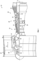
- FIG. 1 schematically illustrates a gas turbine engine 20.
- the gas turbine engine 20 is disclosed herein as a two-spool turbofan that generally incorporates a fan section 22, a compressor section 24, a combustor section 26 and a turbine section 28.
- Alternative engines might include other systems or features.
- the fan section 22 drives air along a bypass flow path B in a bypass duct, while the compressor section 24 drives air along a core flow path C for compression and communication into the combustor section 26 and then expansion through the turbine section 28.
- the exemplary gas turbine engine 20 generally includes a low speed spool 30 and a high speed spool 32 mounted for rotation about an engine central longitudinal axis A relative to an engine static structure 36 via several bearing systems 38. It should be understood that various bearing systems 38 at various locations may alternatively or additionally be provided, and the location of bearing systems 38 may be varied as appropriate to the application.
- the low speed spool 30 generally includes an inner shaft 40 that interconnects a fan 42, a low pressure compressor 44 and a low pressure turbine 46.
- the inner shaft 40 is connected to the fan 42 through a speed change mechanism, which in exemplary gas turbine engine 20 is illustrated as a geared architecture 48 to drive the fan 42 at a lower speed than the low speed spool 30.
- the high speed spool 32 includes an outer shaft 50 that interconnects a high pressure compressor 52 and high pressure turbine 54.
- a combustor 56 is arranged in the gas turbine engine 20 between the high pressure compressor 52 and the high pressure turbine 54.
- the engine static structure 36 is arranged generally between the high pressure turbine 54 and the low pressure turbine 46.
- the engine static structure 36 further supports the bearing systems 38 in the turbine section 28.
- the inner shaft 40 and the outer shaft 50 are concentric and rotate via bearing systems 38 about the engine central longitudinal axis A which is collinear with their longitudinal axes.
- the core airflow is compressed by the low pressure compressor 44 and then the high pressure compressor 52, is mixed and burned with fuel in the combustor 56 and is then expanded over the high pressure turbine 54 and the low pressure turbine 46.
- the high and low pressure turbines 54 and 46 rotationally drive the low speed spool 30 and the high speed spool 32, respectively, in response to the expansion.
- geared architecture 48 may be located aft of the combustor section 26 or even aft of the turbine section 28, and the fan section 22 may be positioned forward or aft of the location of geared architecture 48.
- An oil lubrication system can be provided that includes an oil pump, sometimes referred to as a main pump, and a network of conduits and nozzles to feed the bearings with oil.
- This oil is contained in bearing cavities, typically formed inside annular bearing chambers.
- a scavenge system having one or more scavenge lines extending from the bearing chambers and one or more scavenge pumps can be used to recover the oil, which can be in the form of an oil foam at that stage. Air/oil separation and filtering is typically provided for before returning the processed oil to the bearings.
- the oil flow pattern generally operates as follows: Oil particles coalesce along internal bearing chamber partitions and form a liquid partition film which contains air bubbles. In the radial space between the rotating shaft and the liquid oil film, a mixture of air and dispersed oil particles swirl in a circumferential direction at a velocity greater than the liquid oil film flow along the partitions. As a result, the oil film flow is exposed to high shear stresses at the air/oil film interface. Film thickness and velocity distributions inside the bearing are driven by the magnitude of that interfacial shear and superimposed effects of gravitational forces.
- air and oil flows are discharged to an oil scavenge system which communicates with the oil sump and which is partially formed within the bearing chamber.
- an additively manufactured component such as a bearing chamber, of the gas turbine engine 20 of FIG. 1 is provided.
- the component (hereinafter referred to as a "bearing chamber") is additively manufactured to include integrally formed thermal heat exchange fins and other surface features as well as negative features so that the thermal heat exchange fins are weight neutral.
- the design of the thermal heat exchange fins can be informed by a heat map of the component which illustrates where the component is exposed to the highest temperatures during at least additive manufacturing (i.e., powder bed fusion or LBF-LB processes) and thus needs the most heat exchange capability to dissipate the heat.
- the thermal heat exchange fins can be configured to form channels to direct oil to targeted areas for increased cooling capability.
- a bearing chamber 201 is provided and includes an additively manufactured bearing chamber body 210 and heat exchange fins 220.
- the heat exchange fins 220 are additively manufactured and integrally formed with a surface 211 of the bearing chamber body 210 and serve to reduce at least first and second thermal effects the bearing chamber 201 is expected to experience during a lifetime thereof (i.e., during additive manufacturing of the bearing chamber body 210, the heat exchange fins 220 and any external part, such as a build plate, which is additively manufactured in support of the bearing chamber body 210 or during both additive manufacturing and operational use, where operational use can include gas turbine engine operations and maintenance or service operations).
- the heat exchange fins 220 can be provided as an array of surface features 221 that are integrally built on the surface 211 of the bearing chamber body 210.
- the heat exchange fins 220 can be arranged to form surface features or channels 222 that are configured to channel fluid, such as oil, therein.
- the heat exchange fins 220 and the channels 222 can serve to promote heat exchange relative to and cooling of the bearing chamber body 210.
- the bearing chamber body 210 is further formed to define one or more weight reduction cavities 230 for weight-neutralizing the heat exchange fins 220.
- the heat exchange fins 220 are integrally built on the surface 211, the heat exchange fins 220 can be wholly or partially removed from the surface 211 for various reasons.
- the heat exchange fins 220 can be wholly or partially removed following completion of the additive manufacturing of the bearing chamber 201 if their presence is deemed no longer useful.
- a method 400 of additively manufacturing a component such as the bearing chamber body 210
- the method 400 includes generating a three-dimensional (3D) model of the component (hereinafter referred to as the "bearing chamber body 210") at block 401, generating a heat map of the 3D model which is illustrative of thermal effects the bearing chamber body 210 is expected to experience during additive manufacturing and operational use at block 402, updating the 3D model to include 3D heat exchange fin models for reducing the thermal effects at block 403 and updating the 3D model with the 3D heat exchange fin models to include 3D weight reduction cavity models for weight-neutralizing the 3D heat exchange fin models at block 404.
- 3D model of the component hereinafter referred to as the "bearing chamber body 210”
- thermal effects the bearing chamber body 210 is expected to experience during additive manufacturing of the bearing chamber body 210 can include, but are not limited to, thermal effects associated with additive manufacturing of the bearing chamber body 210, the heat exchange fins 220 and any external part, such as a build plate, which is additively manufactured in support of the bearing chamber body 210.
- thermal effects the bearing chamber body 210 is expected to experience during operational use can include, but are not limited to, thermal effects associated with gas turbine engine operations and maintenance or service operations.
- the 3D heat exchange fin models can be representative of fins integrally built on the bearing chamber body 210 (i.e., the heat exchange fins 220 of FIGS. 2 and 3 ). In accordance with further embodiments, the 3D heat exchange fin models can be representative of an array of surface features integrally built on the bearing chamber body 210 (i.e., to form the channels 222 of FIGS. 2 and 3 ).
- the method 400 can further include determining whether the 3D heat exchange fin models are effective at reducing the thermal effects at block 405, refining the 3D heat exchange fin models based on a result of the determining at block 406 and repeating the determining and the refining until the determining indicates that the 3D heat exchange fin models are effective at reducing the thermal effects at block 407.
- the method 400 can further include determining whether the 3D weight reduction cavity models are associated with increased stresses in the bearing chamber body 210 at block 408, refining the 3D weight reduction cavity models based on a result of the determining at block 409 and repeating the determining and the refining until the determining indicates that the 3D weight reduction cavity models are not associated with increased stresses at block 410.
- the method 400 can include additively manufacturing the component according to the 3D model, the 3D heat exchange fin models and the 3D weight reduction cavity models at block 411.
- a method 500 of additively manufacturing a component such as the bearing chamber body 210
- the method 500 includes generating a three-dimensional (3D) model of the component (hereinafter referred to as the "bearing chamber body 210") at block 501, generating a first heat map of the 3D model which is illustrative of first thermal effects the bearing chamber body 210 is expected to experience during additive manufacturing at block 502, generating a second heat map of the 3D model which is illustrative of second thermal effects the bearing chamber body 210 is expected to experience during operational use at block 503, updating the 3D model to include 3D heat exchange fin models for reducing the first and second thermal effects at block 504 and updating the 3D model with the 3D heat exchange fin models to include 3D weight reduction cavity models for weight-neutralizing the 3D heat exchange fin models at block 505.
- the first thermal effects the bearing chamber body 210 is expected to experience during additive manufacturing of the bearing chamber body 210 can include, but are not limited to, thermal effects associated with additive manufacturing of the bearing chamber body 210, the heat exchange fins 220 and any external part, such as a build plate, which is additively manufactured in support of the bearing chamber body 210.
- the second thermal effects the bearing chamber body 210 is expected to experience during operational use can include, but are not limited to, thermal effects associated with gas turbine engine operations and maintenance or service operations.
- the 3D heat exchange fin models can be representative of fins integrally built on the bearing chamber body 210 (i.e., the heat exchange fins 220 of FIGS. 2 and 3 ). In accordance with further embodiments, the 3D heat exchange fin models can be representative of an array of surface features integrally built on the bearing chamber body 210 (i.e., to form the channels 222 of FIGS. 2 and 3 ).
- the method 500 can further include determining whether the 3D heat exchange fin models are effective at reducing the first and second thermal effects at block 506, refining the 3D heat exchange fin models based on a result of the determining at block 507 and repeating the determining and the refining until the determining indicates that the 3D heat exchange fin models are effective at reducing the first and second thermal effects at block 508.
- the method 500 can further include determining whether the 3D weight reduction cavity models are associated with increased stresses in the bearing chamber body 210 at block 509, refining the 3D weight reduction cavity models based on a result of the determining at block 510 and repeating the determining and the refining until the determining indicates that the 3D weight reduction cavity models are not associated with increased stresses at block 511.
- the method 500 can include additively manufacturing the component according to the 3D model, the 3D heat exchange fin models and the 3D weight reduction cavity models at block 512.
- the bearing chamber is additively manufactured to include integrally formed thermal heat exchange fins and other surface features as well as negative features so that the thermal heat exchange fins are weight neutral.
- the design of the thermal heat exchange fins can be informed by a heat map of the component which illustrates where the component is exposed to the highest temperatures and thus needs the most heat exchange capability to dissipate the heat.
- the thermal heat exchange fins can be configured to form a channel to collect oil which increases cooling capability.
Landscapes
- Engineering & Computer Science (AREA)
- Chemical & Material Sciences (AREA)
- General Engineering & Computer Science (AREA)
- Manufacturing & Machinery (AREA)
- Mechanical Engineering (AREA)
- Materials Engineering (AREA)
- Combustion & Propulsion (AREA)
- Physics & Mathematics (AREA)
- Plasma & Fusion (AREA)
- Automation & Control Theory (AREA)
- Sliding-Contact Bearings (AREA)
Abstract
Description
- Exemplary embodiments of the present disclosure relate generally to gas turbine engines and, in one embodiment, to a bearing chamber with thermal heat exchange fins.
- In a gas turbine engine, air is compressed in a compressor and compressor air is then mixed with fuel and combusted in a combustor to produce a high-temperture and high-pressure working fluid. This working fluid is directed into a turbine in which the working fluid is expanded to generate power. The generated power drives the rotation of a rotor within the turbine through aerodynamic interactions between the working fluid and turbine blades or airfoils. The rotor can be used to drive rotations of a propeller or to produce electricity in a generator.
- Additively manufactured components, such as a bearing chamber of a gas turbine engine, are susceptible to a significant amount of distortion and residual stress, particularly following various secondary processes such as, for example, a heating process. To avoid this, components can be modified to include thermal heat exchange fins, but this comes at a cost of added weight and complexity.
- Accordingly, a need exists for an additively manufactured bearing chamber with thermal heat exchange fins that does not add weight and complexity to the bearing chamber.
- According to an aspect of the disclosure, a method of additively manufacturing a component is provided and includes generating a three-dimensional (3D) model of the component, generating a heat map of the 3D model which is illustrative of thermal effects the component is expected to experience, updating the 3D model to include 3D heat exchange fin models for reducing the thermal effects and updating the 3D model with the 3D heat exchange fin models to include 3D weight reduction cavity models for weight-neutralizing the 3D heat exchange fin models.
- In an embodiment of the previous embodiment, the component includes a bearing chamber.
- In a further embodiment of any of the previous embodiments, the method further includes determining whether the 3D heat exchange fin models are effective at reducing the thermal effects, refining the 3D heat exchange fin models based on a result of the determining and repeating the determining and the refining until the determining indicates that the 3D heat exchange fin models are effective at reducing the thermal effects.
- In a further embodiment of any of the previous embodiments, the method further includes determining whether the 3D weight reduction cavity models are associated with increased stresses, refining the 3D weight reduction cavity models based on a result of the determining and repeating the determining and the refining until the determining indicates that the 3D weight reduction cavity models are not associated with increased stresses.
- In a further embodiment of any of the previous embodiments, the method further includes additively manufacturing the component according to the 3D model, the 3D heat exchange fin models and the 3D weight reduction cavity models.
- In a further embodiment of any of the previous embodiments, the 3D heat exchange fin models are representative of fins integrally built on the component.
- In a further embodiment of any of the previous embodiments, the 3D heat exchange fin models are representative of an array of surface features integrally built on the component.
- In a further embodiment of any of the previous embodiments, the 3D heat exchange fin models are representative of an array of surface features integrally built on the component and configured to channel oil on a surface of the component.
- According to an aspect of the disclosure, a method of additively manufacturing a bearing chamber is provided and includes generating a three-dimensional (3D) model of the bearing chamber, generating a heat map of the 3D model which is illustrative of thermal effects the bearing chamber is expected to experience during a lifetime thereof, updating the 3D model to include 3D heat exchange fin models for reducing the thermal effects and updating the 3D model with the 3D heat exchange fin models to include 3D weight reduction cavity models for weight-neutralizing the 3D heat exchange fin models.
- In a further embodiment of any of the previous embodiments, the method further includes determining whether the 3D heat exchange fin models are effective at reducing the thermal effects, refining the 3D heat exchange fin models based on a result of the determining and repeating the determining and the refining until the determining indicates that the 3D heat exchange fin models are effective at reducing the thermal effects.
- In a further embodiment of any of the previous embodiments, the method further includes determining whether the 3D weight reduction cavity models are associated with increased stresses, refining the 3D weight reduction cavity models based on a result of the determining and repeating the determining and the refining until the determining indicates that the 3D weight reduction cavity models are not associated with increased stresses.
- In a further embodiment of any of the previous embodiments, the method further includes additively manufacturing the bearing chamber according to the 3D model, the 3D heat exchange fin models and the 3D weight reduction cavity models.
- In a further embodiment of any of the previous embodiments, the 3D heat exchange fin models are representative of fins integrally built on a surface of the bearing chamber.
- In a further embodiment of any of the previous embodiments, the 3D heat exchange fin models are representative of an array of surface features integrally built on a surface of the bearing chamber.
- In a further embodiment of any of the previous embodiments, the 3D heat exchange fin models are representative of an array of surface features integrally built on a surface of the bearing chamber and configured to channel oil thereon.
- According to an aspect of the disclosure, a bearing chamber is provided and includes a bearing chamber body and heat exchange fins integrally formed with the bearing chamber body to reduce thermal effects the bearing chamber is expected to experience during a lifetime thereof. The bearing chamber body defines weight reduction cavities for weight-neutralizing the heat exchange fins.
- In a further embodiment of any of the previous embodiments, the heat exchange fins are integrally built on a surface of the bearing chamber.
- In a further embodiment of any of the previous embodiments, the heat exchange fins are an array of surface features integrally built on a surface of the bearing chamber.
- In a further embodiment of any of the previous embodiments, the heat exchange fins are an array of surface features integrally built on a surface of the bearing chamber and configured to channel oil thereon.
- These and other advantages and features will become more apparent from the following description taken in conjunction with the drawings.
- The following descriptions should not be considered limiting in any way. With reference to the accompanying drawings, like elements are numbered alike:
-
FIG. 1 is a partial cross-sectional view of a gas turbine engine; -
FIG. 2 is a side view of a bearing chamber with thermal heat exchange fins in accordance with embodiments; -
FIG. 3 is a perspective view of an enlarged portion of the bearing chamber and the thermal heat exchange fins in accordance with embodiments; -
FIG. 4 is a flow diagram illustrating a method of additvely manufacturing a bearing chamber in accordance with embodiments; and -
FIG. 5 is a flow diagram illustrating a method of additvely manufacturing a bearing chamber in accordance with further embodiments. - These and other advantages and features will become more apparent from the following description taken in conjunction with the drawings.
- A detailed description of one or more embodiments of the disclosed apparatus and method are presented herein by way of exemplification and not limitation with reference to the Figures.
-
FIG. 1 schematically illustrates agas turbine engine 20. Thegas turbine engine 20 is disclosed herein as a two-spool turbofan that generally incorporates afan section 22, acompressor section 24, acombustor section 26 and aturbine section 28. Alternative engines might include other systems or features. Thefan section 22 drives air along a bypass flow path B in a bypass duct, while thecompressor section 24 drives air along a core flow path C for compression and communication into thecombustor section 26 and then expansion through theturbine section 28. Although depicted as a two-spool turbofan gas turbine engine in the disclosed non-limiting embodiment, it should be understood that the concepts described herein are not limited to use with two-spool turbofans as the teachings may be applied to other types of turbine engines including three-spool architectures. - The exemplary
gas turbine engine 20 generally includes alow speed spool 30 and ahigh speed spool 32 mounted for rotation about an engine central longitudinal axis A relative to an enginestatic structure 36 viaseveral bearing systems 38. It should be understood thatvarious bearing systems 38 at various locations may alternatively or additionally be provided, and the location ofbearing systems 38 may be varied as appropriate to the application. - The
low speed spool 30 generally includes aninner shaft 40 that interconnects afan 42, alow pressure compressor 44 and alow pressure turbine 46. Theinner shaft 40 is connected to thefan 42 through a speed change mechanism, which in exemplarygas turbine engine 20 is illustrated as a gearedarchitecture 48 to drive thefan 42 at a lower speed than thelow speed spool 30. Thehigh speed spool 32 includes anouter shaft 50 that interconnects ahigh pressure compressor 52 andhigh pressure turbine 54. Acombustor 56 is arranged in thegas turbine engine 20 between thehigh pressure compressor 52 and thehigh pressure turbine 54. The enginestatic structure 36 is arranged generally between thehigh pressure turbine 54 and thelow pressure turbine 46. The enginestatic structure 36 further supports thebearing systems 38 in theturbine section 28. Theinner shaft 40 and theouter shaft 50 are concentric and rotate viabearing systems 38 about the engine central longitudinal axis A which is collinear with their longitudinal axes. - The core airflow is compressed by the
low pressure compressor 44 and then thehigh pressure compressor 52, is mixed and burned with fuel in thecombustor 56 and is then expanded over thehigh pressure turbine 54 and thelow pressure turbine 46. The high andlow pressure turbines low speed spool 30 and thehigh speed spool 32, respectively, in response to the expansion. It will be appreciated that each of the positions of thefan section 22,compressor section 24,combustor section 26,turbine section 28, and fandrive gear system 48 may be varied. For example, gearedarchitecture 48 may be located aft of thecombustor section 26 or even aft of theturbine section 28, and thefan section 22 may be positioned forward or aft of the location of gearedarchitecture 48. - Within the
gas turbine engine 20, bearings are used to provide smooth relative rotation between the various shafts and non-rotating components and/or between two shafts which rotate at different speeds. An oil lubrication system can be provided that includes an oil pump, sometimes referred to as a main pump, and a network of conduits and nozzles to feed the bearings with oil. This oil is contained in bearing cavities, typically formed inside annular bearing chambers. A scavenge system having one or more scavenge lines extending from the bearing chambers and one or more scavenge pumps can be used to recover the oil, which can be in the form of an oil foam at that stage. Air/oil separation and filtering is typically provided for before returning the processed oil to the bearings. - In the bearing chambers, air and oil flows mix and generate a flow pattern about the engine central longitudinal axis A. The oil flow pattern generally operates as follows: Oil particles coalesce along internal bearing chamber partitions and form a liquid partition film which contains air bubbles. In the radial space between the rotating shaft and the liquid oil film, a mixture of air and dispersed oil particles swirl in a circumferential direction at a velocity greater than the liquid oil film flow along the partitions. As a result, the oil film flow is exposed to high shear stresses at the air/oil film interface. Film thickness and velocity distributions inside the bearing are driven by the magnitude of that interfacial shear and superimposed effects of gravitational forces.
- To achieve bearing chamber functionality, air and oil flows are discharged to an oil scavenge system which communicates with the oil sump and which is partially formed within the bearing chamber.
- As will be described below, an additively manufactured component, such as a bearing chamber, of the
gas turbine engine 20 ofFIG. 1 is provided. The component (hereinafter referred to as a "bearing chamber") is additively manufactured to include integrally formed thermal heat exchange fins and other surface features as well as negative features so that the thermal heat exchange fins are weight neutral. The design of the thermal heat exchange fins can be informed by a heat map of the component which illustrates where the component is exposed to the highest temperatures during at least additive manufacturing (i.e., powder bed fusion or LBF-LB processes) and thus needs the most heat exchange capability to dissipate the heat. The thermal heat exchange fins can be configured to form channels to direct oil to targeted areas for increased cooling capability. - With continued reference to
FIG. 1 and with additional reference toFIGS. 2 and3 , a bearingchamber 201 is provided and includes an additively manufacturedbearing chamber body 210 andheat exchange fins 220. Theheat exchange fins 220 are additively manufactured and integrally formed with asurface 211 of the bearingchamber body 210 and serve to reduce at least first and second thermal effects the bearingchamber 201 is expected to experience during a lifetime thereof (i.e., during additive manufacturing of the bearingchamber body 210, theheat exchange fins 220 and any external part, such as a build plate, which is additively manufactured in support of the bearingchamber body 210 or during both additive manufacturing and operational use, where operational use can include gas turbine engine operations and maintenance or service operations). In accordance with embodiments, theheat exchange fins 220 can be provided as an array of surface features 221 that are integrally built on thesurface 211 of the bearingchamber body 210. In some cases, theheat exchange fins 220 can be arranged to form surface features orchannels 222 that are configured to channel fluid, such as oil, therein. As such, theheat exchange fins 220 and thechannels 222 can serve to promote heat exchange relative to and cooling of the bearingchamber body 210. The bearingchamber body 210 is further formed to define one or moreweight reduction cavities 230 for weight-neutralizing theheat exchange fins 220. - It is to be understood that, while the
heat exchange fins 220 are integrally built on thesurface 211, theheat exchange fins 220 can be wholly or partially removed from thesurface 211 for various reasons. For example, theheat exchange fins 220 can be wholly or partially removed following completion of the additive manufacturing of the bearingchamber 201 if their presence is deemed no longer useful. - With reference to
FIG. 4 , amethod 400 of additively manufacturing a component, such as the bearingchamber body 210, is provided. As shown inFIG. 4 , themethod 400 includes generating a three-dimensional (3D) model of the component (hereinafter referred to as the "bearingchamber body 210") atblock 401, generating a heat map of the 3D model which is illustrative of thermal effects the bearingchamber body 210 is expected to experience during additive manufacturing and operational use atblock 402, updating the 3D model to include 3D heat exchange fin models for reducing the thermal effects atblock 403 and updating the 3D model with the 3D heat exchange fin models to include 3D weight reduction cavity models for weight-neutralizing the 3D heat exchange fin models atblock 404. - In accordance with embodiments, thermal effects the bearing
chamber body 210 is expected to experience during additive manufacturing of the bearingchamber body 210 can include, but are not limited to, thermal effects associated with additive manufacturing of the bearingchamber body 210, theheat exchange fins 220 and any external part, such as a build plate, which is additively manufactured in support of the bearingchamber body 210. In accordance with embodiments, thermal effects the bearingchamber body 210 is expected to experience during operational use can include, but are not limited to, thermal effects associated with gas turbine engine operations and maintenance or service operations. - In accordance with embodiments, the 3D heat exchange fin models can be representative of fins integrally built on the bearing chamber body 210 (i.e., the
heat exchange fins 220 ofFIGS. 2 and3 ). In accordance with further embodiments, the 3D heat exchange fin models can be representative of an array of surface features integrally built on the bearing chamber body 210 (i.e., to form thechannels 222 ofFIGS. 2 and3 ). - The
method 400 can further include determining whether the 3D heat exchange fin models are effective at reducing the thermal effects atblock 405, refining the 3D heat exchange fin models based on a result of the determining atblock 406 and repeating the determining and the refining until the determining indicates that the 3D heat exchange fin models are effective at reducing the thermal effects atblock 407. In addition, themethod 400 can further include determining whether the 3D weight reduction cavity models are associated with increased stresses in thebearing chamber body 210 atblock 408, refining the 3D weight reduction cavity models based on a result of the determining atblock 409 and repeating the determining and the refining until the determining indicates that the 3D weight reduction cavity models are not associated with increased stresses atblock 410. Subsequently, themethod 400 can include additively manufacturing the component according to the 3D model, the 3D heat exchange fin models and the 3D weight reduction cavity models atblock 411. - With reference to
FIG. 5 , amethod 500 of additively manufacturing a component, such as the bearingchamber body 210, is provided. As shown inFIG. 5 , themethod 500 includes generating a three-dimensional (3D) model of the component (hereinafter referred to as the "bearingchamber body 210") atblock 501, generating a first heat map of the 3D model which is illustrative of first thermal effects the bearingchamber body 210 is expected to experience during additive manufacturing atblock 502, generating a second heat map of the 3D model which is illustrative of second thermal effects the bearingchamber body 210 is expected to experience during operational use atblock 503, updating the 3D model to include 3D heat exchange fin models for reducing the first and second thermal effects atblock 504 and updating the 3D model with the 3D heat exchange fin models to include 3D weight reduction cavity models for weight-neutralizing the 3D heat exchange fin models atblock 505. - In accordance with embodiments, the first thermal effects the bearing
chamber body 210 is expected to experience during additive manufacturing of the bearingchamber body 210 can include, but are not limited to, thermal effects associated with additive manufacturing of the bearingchamber body 210, theheat exchange fins 220 and any external part, such as a build plate, which is additively manufactured in support of the bearingchamber body 210. In accordance with embodiments, the second thermal effects the bearingchamber body 210 is expected to experience during operational use can include, but are not limited to, thermal effects associated with gas turbine engine operations and maintenance or service operations. - In accordance with embodiments, the 3D heat exchange fin models can be representative of fins integrally built on the bearing chamber body 210 (i.e., the
heat exchange fins 220 ofFIGS. 2 and3 ). In accordance with further embodiments, the 3D heat exchange fin models can be representative of an array of surface features integrally built on the bearing chamber body 210 (i.e., to form thechannels 222 ofFIGS. 2 and3 ). - The
method 500 can further include determining whether the 3D heat exchange fin models are effective at reducing the first and second thermal effects atblock 506, refining the 3D heat exchange fin models based on a result of the determining atblock 507 and repeating the determining and the refining until the determining indicates that the 3D heat exchange fin models are effective at reducing the first and second thermal effects atblock 508. In addition, themethod 500 can further include determining whether the 3D weight reduction cavity models are associated with increased stresses in thebearing chamber body 210 atblock 509, refining the 3D weight reduction cavity models based on a result of the determining atblock 510 and repeating the determining and the refining until the determining indicates that the 3D weight reduction cavity models are not associated with increased stresses atblock 511. Subsequently, themethod 500 can include additively manufacturing the component according to the 3D model, the 3D heat exchange fin models and the 3D weight reduction cavity models atblock 512. - Benefits of the features described herein are the provision of a bearing chamber of a gas turbine engine. The bearing chamber is additively manufactured to include integrally formed thermal heat exchange fins and other surface features as well as negative features so that the thermal heat exchange fins are weight neutral. The design of the thermal heat exchange fins can be informed by a heat map of the component which illustrates where the component is exposed to the highest temperatures and thus needs the most heat exchange capability to dissipate the heat. The thermal heat exchange fins can be configured to form a channel to collect oil which increases cooling capability.
- The term "about" is intended to include the degree of error associated with measurement of the particular quantity based upon the equipment available at the time of filing the application.
- The terminology used herein is for the purpose of describing particular embodiments only and is not intended to be limiting of the present disclosure. As used herein, the singular forms "a", "an" and "the" are intended to include the plural forms as well, unless the context clearly indicates otherwise. It will be further understood that the terms "comprises" and/or "comprising," when used in this specification, specify the presence of stated features, integers, steps, operations, elements, and/or components, but do not preclude the presence or addition of one or more other features, integers, steps, operations, element components, and/or groups thereof.
- While the present disclosure has been described with reference to an exemplary embodiment or embodiments, it will be understood by those skilled in the art that various changes may be made and equivalents may be substituted for elements thereof without departing from the scope of the present disclosure. In addition, many modifications may be made to adapt a particular situation or material to the teachings of the present disclosure without departing from the essential scope thereof. Therefore, it is intended that the present disclosure not be limited to the particular embodiment disclosed as the best mode contemplated for carrying out this present disclosure, but that the present disclosure will include all embodiments falling within the scope of the claims.
Claims (15)
- A method of additively manufacturing a component, the method comprising:generating a three-dimensional (3D) model of the component;generating a heat map of the 3D model which is illustrative of thermal effects the component is expected to experience;updating the 3D model to include 3D heat exchange fin models for reducing the thermal effects; andupdating the 3D model with the 3D heat exchange fin models to include 3D weight reduction cavity models for weight-neutralizing the 3D heat exchange fin models.
- The method according to claim 1, wherein the component comprises a bearing chamber (201).
- The method according to claim 1 or 2, further comprising:determining whether the 3D heat exchange fin models are effective at reducing the thermal effects;refining the 3D heat exchange fin models based on a result of the determining; andrepeating the determining and the refining until the determining indicates that the 3D heat exchange fin models are effective at reducing the thermal effects.
- The method according to claim 1, 2 or 3, further comprising:determining whether the 3D weight reduction cavity models are associated with increased stresses;refining the 3D weight reduction cavity models based on a result of the determining; andrepeating the determining and the refining until the determining indicates that the 3D weight reduction cavity models are not associated with increased stresses.
- The method according to any preceding claim, further comprising additively manufacturing the component according to the 3D model, the 3D heat exchange fin models and the 3D weight reduction cavity models.
- The method according to any preceding claim, wherein the 3D heat exchange fin models are representative of fins (220) integrally built on the component.
- The method according to any of claims 1 to 5, wherein the 3D heat exchange fin models are representative of an array of surface features (221) integrally built on the component.
- The method according to any of claims 1 to 5, wherein the 3D heat exchange fin models are representative of an array of surface features (221) integrally built on the component and configured to channel oil on a surface of the component.
- A method of additively manufacturing a bearing chamber (201), the method comprising:generating a three-dimensional (3D) model of the bearing chamber (201);generating a heat map of the 3D model which is illustrative of thermal effects the bearing chamber (201) is expected to experience during a lifetime thereof;updating the 3D model to include 3D heat exchange fin models for reducing the thermal effects; andupdating the 3D model with the 3D heat exchange fin models to include 3D weight reduction cavity models for weight-neutralizing the 3D heat exchange fin models.
- The method according to claim 9, further comprising:determining whether the 3D heat exchange fin models are effective at reducing the thermal effects;refining the 3D heat exchange fin models based on a result of the determining; andrepeating the determining and the refining until the determining indicates that the 3D heat exchange fin models are effective at reducing the thermal effects.
- The method according to claim 9 or 10, further comprising:determining whether the 3D weight reduction cavity models are associated with increased stresses;refining the 3D weight reduction cavity models based on a result of the determining; andrepeating the determining and the refining until the determining indicates that the 3D weight reduction cavity models are not associated with increased stresses.
- The method according to claim 9, 10 or 11, further comprising additively manufacturing the bearing chamber (201) according to the 3D model, the 3D heat exchange fin models and the 3D weight reduction cavity models.
- The method according to any of claims 9 to 12, wherein:the 3D heat exchange fin models are representative of fins (220) integrally built on a surface (211) of the bearing chamber (201); orthe 3D heat exchange fin models are representative of an array of surface features (221) integrally built on a surface (211) of the bearing chamber (201) and optionally configured to channel oil thereon.
- A bearing chamber (201), comprising:a bearing chamber body (210); andheat exchange fins (220) integrally formed with the bearing chamber body (210) to reduce thermal effects the bearing chamber (201) is expected to experience during a lifetime thereof,the bearing chamber body (210) defining weight reduction cavities (230) for weight-neutralizing the heat exchange fins (220).
- The bearing chamber (201) according to claim 14, wherein:the heat exchange fins (220) are integrally built on a surface (211) of the bearing chamber (201); orthe heat exchange fins (220) are an array of surface features (221) integrally built on a surface (211) of the bearing chamber (201) and optionally configured to channel oil thereon.
Applications Claiming Priority (1)
| Application Number | Priority Date | Filing Date | Title |
|---|---|---|---|
| US202263423389P | 2022-11-07 | 2022-11-07 |
Publications (1)
| Publication Number | Publication Date |
|---|---|
| EP4365416A1 true EP4365416A1 (en) | 2024-05-08 |
Family
ID=88731588
Family Applications (1)
| Application Number | Title | Priority Date | Filing Date |
|---|---|---|---|
| EP23208233.9A Pending EP4365416A1 (en) | 2022-11-07 | 2023-11-07 | Bearing chamber with thermal heat exchange fins |
Country Status (2)
| Country | Link |
|---|---|
| US (1) | US12546234B2 (en) |
| EP (1) | EP4365416A1 (en) |
Citations (4)
| Publication number | Priority date | Publication date | Assignee | Title |
|---|---|---|---|---|
| US20140119913A1 (en) * | 2012-11-01 | 2014-05-01 | United Technologies Corporation | Gas Turbine Engine With Bearing Compartment Wall Cooling |
| US20170248191A1 (en) * | 2016-02-25 | 2017-08-31 | United Technologies Corporation | Systems and methods for oil damping with textured damper surfaces |
| US20210033003A1 (en) * | 2018-03-23 | 2021-02-04 | Safran Aircraft Engines | Bearing support for an aircraft engine manufactured by additive manufacturing |
| US10968774B2 (en) * | 2018-10-11 | 2021-04-06 | Pratt & Whitney Canada Corp. | Bearing housing with baffles |
Family Cites Families (22)
| Publication number | Priority date | Publication date | Assignee | Title |
|---|---|---|---|---|
| EP2873810B2 (en) * | 2013-11-18 | 2020-07-01 | Safran Aero Boosters SA | Annular cover for defining a turbomachine lubrication chamber |
| US10989141B2 (en) * | 2014-11-24 | 2021-04-27 | Nirvana Energy Systems, Inc. | Secure control system for multistage thermo acoustic micro-CHP generator |
| EP3369014B1 (en) | 2015-10-28 | 2021-11-03 | Siemens Industry Software Inc. | System and method for optimizing tool paths based on thermal/structural simulations of a part being produced via a 3d-printer |
| JP2017180177A (en) * | 2016-03-29 | 2017-10-05 | 三菱重工コンプレッサ株式会社 | Impeller manufacturing method and impeller by hot melt additive manufacturing using different materials |
| US9656429B1 (en) * | 2016-08-09 | 2017-05-23 | Arevo, Inc. | Systems and methods for structurally analyzing and printing parts |
| US10494941B2 (en) * | 2016-10-17 | 2019-12-03 | United Technologies Corporation | Seal face plate cooling |
| KR20200021943A (en) * | 2017-06-28 | 2020-03-02 | 술저 매니지멘트 에이지 | Flow machine with bearing housing and bearing housing for flow machine |
| EP3563269B1 (en) | 2017-09-07 | 2024-12-11 | Siemens Industry Software Inc. | Heat sink support structures in additive manufacturing |
| DE102018202083A1 (en) * | 2018-02-09 | 2019-08-14 | MTU Aero Engines AG | STORAGE CHAMBER HOUSING FOR A FLOW MACHINE |
| US11306614B2 (en) * | 2018-10-04 | 2022-04-19 | Rolls-Royce Corporation | Sump auxiliary vent system |
| US12044136B2 (en) * | 2019-04-29 | 2024-07-23 | Transportation Ip Holdings, Llc | Rotary assembly |
| US11168605B2 (en) | 2019-10-11 | 2021-11-09 | Southwest Research Institute | Manufacture of heat transfer jackets |
| US11655715B2 (en) * | 2019-12-23 | 2023-05-23 | Special Aerospace Services, LLC | Surface topology manipulation for performance enhancement of additively manufactured fluid-interacting components |
| US11498296B2 (en) | 2020-04-28 | 2022-11-15 | The Boeing Company | Print on demand heat blanket system |
| CN112032613A (en) * | 2020-08-11 | 2020-12-04 | 南京嘉视信电子有限公司 | Tunnel lamp capable of dissipating heat quickly and design method thereof |
| US11794415B2 (en) * | 2020-09-23 | 2023-10-24 | Ut-Battelle, Llc | System and method for simulation-assisted additive manufacturing involving estimating anisotropic deformation |
| US20220284154A1 (en) * | 2021-02-09 | 2022-09-08 | Nutech Ventures | Thermal modeling of additive manufacturing using progressive horizontal subsections |
| US20230306160A1 (en) * | 2022-03-28 | 2023-09-28 | Palo Alto Research Center Incorporated | Method and system for automated design generation for additive manufacturing utilizing machine learning based surrogate model for cracking |
| US20240135048A1 (en) * | 2022-10-13 | 2024-04-25 | Garrett McDaniel | Additively manufactured, thermally optimized rocket motor nozzle design |
| US20240151266A1 (en) * | 2022-11-07 | 2024-05-09 | Rtx Corporation | Thermal zone cooling in a bearing compartment |
| US20240403522A1 (en) * | 2023-05-31 | 2024-12-05 | Microsoft Technology Licensing, Llc | Microfluidics thermal management flow patterns and schemas |
| US12442313B2 (en) * | 2023-08-24 | 2025-10-14 | Solar Turbines Incorporated | Additive manufactured bearing cap for temperature reduction on bearing cap wetted wall |
-
2023
- 2023-11-07 US US18/387,566 patent/US12546234B2/en active Active
- 2023-11-07 EP EP23208233.9A patent/EP4365416A1/en active Pending
Patent Citations (4)
| Publication number | Priority date | Publication date | Assignee | Title |
|---|---|---|---|---|
| US20140119913A1 (en) * | 2012-11-01 | 2014-05-01 | United Technologies Corporation | Gas Turbine Engine With Bearing Compartment Wall Cooling |
| US20170248191A1 (en) * | 2016-02-25 | 2017-08-31 | United Technologies Corporation | Systems and methods for oil damping with textured damper surfaces |
| US20210033003A1 (en) * | 2018-03-23 | 2021-02-04 | Safran Aircraft Engines | Bearing support for an aircraft engine manufactured by additive manufacturing |
| US10968774B2 (en) * | 2018-10-11 | 2021-04-06 | Pratt & Whitney Canada Corp. | Bearing housing with baffles |
Also Published As
| Publication number | Publication date |
|---|---|
| US12546234B2 (en) | 2026-02-10 |
| US20240151156A1 (en) | 2024-05-09 |
Similar Documents
| Publication | Publication Date | Title |
|---|---|---|
| EP3236093B1 (en) | Thrust air bearing | |
| EP3088688A1 (en) | Lubrication system for gas turbine engines | |
| CN105525993A (en) | Heat exchanger assembly | |
| US10247106B2 (en) | Method and system for rotating air seal with integral flexible heat shield | |
| CN113833827A (en) | Gear assembly for an aircraft engine having a lubricant reservoir pocket | |
| EP4365416A1 (en) | Bearing chamber with thermal heat exchange fins | |
| EP4365417A1 (en) | Bearing chamber with mapped thermal heat exchange fins | |
| CN115199404B (en) | Flow structures for turbine engines | |
| CN107916994B (en) | Gas turbine engine and method for operating its sump pressurization assembly | |
| EP4365415A1 (en) | Annular oil distributor for bearing chamber | |
| EP4360779A1 (en) | Hybrid bearing forged flange | |
| US11525400B2 (en) | System for rotor assembly thermal gradient reduction | |
| US20240227012A9 (en) | Hybrid bearing forged flange | |
| EP3971389A1 (en) | Anti-vortex tube retaining ring and bore basket | |
| CN115030957A (en) | Bearing system with independent adaptive stiffness support | |
| EP4361408A1 (en) | Oil nozzle for bearing chamber | |
| EP3663517A1 (en) | Baffle, corresponding component and gas turbine engine | |
| EP4365413A1 (en) | Support structure and spring for bearing compartment | |
| EP4571054A1 (en) | Outer air seal (oas) with improved mating with first stage casing | |
| US12006833B2 (en) | Shaft for a turbomachine | |
| EP4365414A1 (en) | Bearing compartment with spring damping |
Legal Events
| Date | Code | Title | Description |
|---|---|---|---|
| PUAI | Public reference made under article 153(3) epc to a published international application that has entered the european phase |
Free format text: ORIGINAL CODE: 0009012 |
|
| STAA | Information on the status of an ep patent application or granted ep patent |
Free format text: STATUS: THE APPLICATION HAS BEEN PUBLISHED |
|
| AK | Designated contracting states |
Kind code of ref document: A1 Designated state(s): AL AT BE BG CH CY CZ DE DK EE ES FI FR GB GR HR HU IE IS IT LI LT LU LV MC ME MK MT NL NO PL PT RO RS SE SI SK SM TR |
|
| STAA | Information on the status of an ep patent application or granted ep patent |
Free format text: STATUS: REQUEST FOR EXAMINATION WAS MADE |
|
| 17P | Request for examination filed |
Effective date: 20241108 |
|
| RBV | Designated contracting states (corrected) |
Designated state(s): AL AT BE BG CH CY CZ DE DK EE ES FI FR GB GR HR HU IE IS IT LI LT LU LV MC ME MK MT NL NO PL PT RO RS SE SI SK SM TR |
|
| STAA | Information on the status of an ep patent application or granted ep patent |
Free format text: STATUS: EXAMINATION IS IN PROGRESS |
|
| 17Q | First examination report despatched |
Effective date: 20260102 |