EP4365415A1 - Annular oil distributor for bearing chamber - Google Patents
Annular oil distributor for bearing chamber Download PDFInfo
- Publication number
- EP4365415A1 EP4365415A1 EP23208214.9A EP23208214A EP4365415A1 EP 4365415 A1 EP4365415 A1 EP 4365415A1 EP 23208214 A EP23208214 A EP 23208214A EP 4365415 A1 EP4365415 A1 EP 4365415A1
- Authority
- EP
- European Patent Office
- Prior art keywords
- bearing chamber
- oil
- interior
- annular manifold
- interior cavity
- Prior art date
- Legal status (The legal status is an assumption and is not a legal conclusion. Google has not performed a legal analysis and makes no representation as to the accuracy of the status listed.)
- Pending
Links
Images




Classifications
-
- F—MECHANICAL ENGINEERING; LIGHTING; HEATING; WEAPONS; BLASTING
- F01—MACHINES OR ENGINES IN GENERAL; ENGINE PLANTS IN GENERAL; STEAM ENGINES
- F01D—NON-POSITIVE DISPLACEMENT MACHINES OR ENGINES, e.g. STEAM TURBINES
- F01D25/00—Component parts, details, or accessories, not provided for in, or of interest apart from, other groups
- F01D25/18—Lubricating arrangements
-
- B—PERFORMING OPERATIONS; TRANSPORTING
- B22—CASTING; POWDER METALLURGY
- B22F—WORKING METALLIC POWDER; MANUFACTURE OF ARTICLES FROM METALLIC POWDER; MAKING METALLIC POWDER; APPARATUS OR DEVICES SPECIALLY ADAPTED FOR METALLIC POWDER
- B22F5/00—Manufacture of workpieces or articles from metallic powder characterised by the special shape of the product
- B22F5/009—Manufacture of workpieces or articles from metallic powder characterised by the special shape of the product of turbine components other than turbine blades
-
- F—MECHANICAL ENGINEERING; LIGHTING; HEATING; WEAPONS; BLASTING
- F01—MACHINES OR ENGINES IN GENERAL; ENGINE PLANTS IN GENERAL; STEAM ENGINES
- F01D—NON-POSITIVE DISPLACEMENT MACHINES OR ENGINES, e.g. STEAM TURBINES
- F01D25/00—Component parts, details, or accessories, not provided for in, or of interest apart from, other groups
- F01D25/16—Arrangement of bearings; Supporting or mounting bearings in casings
- F01D25/162—Bearing supports
- F01D25/164—Flexible supports; Vibration damping means associated with the bearing
-
- F—MECHANICAL ENGINEERING; LIGHTING; HEATING; WEAPONS; BLASTING
- F02—COMBUSTION ENGINES; HOT-GAS OR COMBUSTION-PRODUCT ENGINE PLANTS
- F02C—GAS-TURBINE PLANTS; AIR INTAKES FOR JET-PROPULSION PLANTS; CONTROLLING FUEL SUPPLY IN AIR-BREATHING JET-PROPULSION PLANTS
- F02C7/00—Features, components parts, details or accessories, not provided for in, or of interest apart form groups F02C1/00 - F02C6/00; Air intakes for jet-propulsion plants
- F02C7/06—Arrangements of bearings; Lubricating
-
- B—PERFORMING OPERATIONS; TRANSPORTING
- B33—ADDITIVE MANUFACTURING TECHNOLOGY
- B33Y—ADDITIVE MANUFACTURING, i.e. MANUFACTURING OF THREE-DIMENSIONAL [3D] OBJECTS BY ADDITIVE DEPOSITION, ADDITIVE AGGLOMERATION OR ADDITIVE LAYERING, e.g. BY 3D PRINTING, STEREOLITHOGRAPHY OR SELECTIVE LASER SINTERING
- B33Y80/00—Products made by additive manufacturing
-
- F—MECHANICAL ENGINEERING; LIGHTING; HEATING; WEAPONS; BLASTING
- F05—INDEXING SCHEMES RELATING TO ENGINES OR PUMPS IN VARIOUS SUBCLASSES OF CLASSES F01-F04
- F05D—INDEXING SCHEME FOR ASPECTS RELATING TO NON-POSITIVE-DISPLACEMENT MACHINES OR ENGINES, GAS-TURBINES OR JET-PROPULSION PLANTS
- F05D2230/00—Manufacture
- F05D2230/30—Manufacture with deposition of material
-
- F—MECHANICAL ENGINEERING; LIGHTING; HEATING; WEAPONS; BLASTING
- F05—INDEXING SCHEMES RELATING TO ENGINES OR PUMPS IN VARIOUS SUBCLASSES OF CLASSES F01-F04
- F05D—INDEXING SCHEME FOR ASPECTS RELATING TO NON-POSITIVE-DISPLACEMENT MACHINES OR ENGINES, GAS-TURBINES OR JET-PROPULSION PLANTS
- F05D2230/00—Manufacture
- F05D2230/30—Manufacture with deposition of material
- F05D2230/31—Layer deposition
-
- F—MECHANICAL ENGINEERING; LIGHTING; HEATING; WEAPONS; BLASTING
- F05—INDEXING SCHEMES RELATING TO ENGINES OR PUMPS IN VARIOUS SUBCLASSES OF CLASSES F01-F04
- F05D—INDEXING SCHEME FOR ASPECTS RELATING TO NON-POSITIVE-DISPLACEMENT MACHINES OR ENGINES, GAS-TURBINES OR JET-PROPULSION PLANTS
- F05D2260/00—Function
- F05D2260/98—Lubrication
Definitions
- Exemplary embodiments of the present disclosure relate generally to gas turbine engines and, in one embodiment, to an annular oil distributor for a bearing chamber of a gas turbine engine.
- a gas turbine engine air is compressed in a compressor and compressor air is then mixed with fuel and combusted in a combustor to produce a high-temperture and high-pressure working fluid.
- This working fluid is directed into a turbine in which the working fluid is expanded to generate power.
- the generated power drives the rotation of a rotor within the turbine through aerodynamic interactions between the working fluid and turbine blades or airfoils.
- the rotor can be used to drive rotations of a propeller or to produce electricity in a generator.
- Certain parts, such as a bearing chamber, in a gas turbine engine need a supply of oil for cooling.
- this oil is supplied via nozzles.
- a problem with the conventional nozzles is that they are expensive and require significant numbers of additional parts for fastening the nozzles in place.
- an oil distributor for a bearing chamber for a component.
- the oil distributor includes an outer annular manifold, which defines a first interior cavity receptive of pressurized oil, an inner annular manifold, which defines a second interior cavity and comprises an interior facing surface defining holes respectively communicative with the second interior cavity and one or more support struts by which the inner annular manifold is supported within the outer annular manifold.
- Each of the one or more support struts defines interior lines by which the pressurized oil flows from the first interior cavity to the second interior cavity and to the holes.
- the component includes a bearing chamber.
- the oil distributor is additively manufactured with the bearing chamber.
- the outer annular manifold is integrally formed with an interior surface of the bearing chamber.
- the outer annular manifold includes a squirrel cage with linear supports through which the pressurized oil is flowable.
- each of the one or more support struts has a narrowing taper with decreasing radial distance from the inner annular manifold.
- the interior facing surface is cylindrical and the holes are arrayed in a lattice along the interior facing surface.
- a bearing chamber includes one or more nozzles and an oil distributor.
- the oil distributor includes an outer annular manifold, which is integrally formed with an interior surface of the bearing chamber and which is integrally formed with an interior surface of the bearing chamber and which defines a first interior cavity receptive of pressurized oil, an inner annular manifold, which defines a second interior cavity and includes an interior facing surface defining holes respectively communicative with the second interior cavity and one or more support struts by which the inner annular manifold is supported within the outer annular manifold.
- Each of the one or more support struts defines interior lines by which the pressurized oil flows from the first interior cavity to the second interior cavity and to the holes.
- each of the one or more nozzles is configured to output oil toward a surface of the bearing chamber.
- the oil distributor and each of the one or more nozzles are configured to output oil toward a different surface of the bearing chamber.
- the oil distributor is additively manufactured with the bearing chamber.
- the outer annular manifold includes a squirrel cage with linear supports through which the pressurized oil is flowable.
- each of the one or more support struts has a narrowing taper with decreasing radial distance from the inner annular manifold.
- the interior facing surface is cylindrical and the holes are arrayed in a lattice along the interior facing surface.
- a method of manufacturing a bearing chamber includes additively manufacturing the bearing chamber and additively manufacturing an oil distributor integrally with the bearing chamber.
- the oil distributor includes an outer annular manifold, which is integrally formed with an interior surface of the bearing chamber and which defines a first interior cavity receptive of pressurized oil, an inner annular manifold, which defines a second interior cavity and comprises an interior facing surface defining holes respectively communicative with the second interior cavity and one or more support struts by which the inner annular manifold is supported within the outer annular manifold.
- Each of the one or more support struts defines interior lines by which the pressurized oil flows from the first interior cavity to the second interior cavity and to the holes.
- the method further includes additively manufacturing one or more nozzles integrally with the bearing chamber.
- each of the one or more nozzles is configured to output oil toward a surface of the bearing chamber.
- the oil distributor and each of the one or more nozzles are configured to output oil toward different surfaces of the bearing chamber.
- FIG. 1 schematically illustrates a gas turbine engine 20.
- the gas turbine engine 20 is disclosed herein as a two-spool turbofan that generally incorporates a fan section 22, a compressor section 24, a combustor section 26 and a turbine section 28.
- Alternative engines might include other systems or features.
- the fan section 22 drives air along a bypass flow path B in a bypass duct, while the compressor section 24 drives air along a core flow path C for compression and communication into the combustor section 26 and then expansion through the turbine section 28.
- the exemplary gas turbine engine 20 generally includes a low speed spool 30 and a high speed spool 32 mounted for rotation about an engine central longitudinal axis A relative to an engine static structure 36 via several bearing systems 38. It should be understood that various bearing systems 38 at various locations may alternatively or additionally be provided, and the location of bearing systems 38 may be varied as appropriate to the application.
- the low speed spool 30 generally includes an inner shaft 40 that interconnects a fan 42, a low pressure compressor 44 and a low pressure turbine 46.
- the inner shaft 40 is connected to the fan 42 through a speed change mechanism, which in exemplary gas turbine engine 20 is illustrated as a geared architecture 48 to drive the fan 42 at a lower speed than the low speed spool 30.
- the high speed spool 32 includes an outer shaft 50 that interconnects a high pressure compressor 52 and high pressure turbine 54.
- a combustor 56 is arranged in the gas turbine engine 20 between the high pressure compressor 52 and the high pressure turbine 54.
- the engine static structure 36 is arranged generally between the high pressure turbine 54 and the low pressure turbine 46.
- the engine static structure 36 further supports the bearing systems 38 in the turbine section 28.
- the inner shaft 40 and the outer shaft 50 are concentric and rotate via bearing systems 38 about the engine central longitudinal axis A which is collinear with their longitudinal axes.
- the core airflow is compressed by the low pressure compressor 44 and then the high pressure compressor 52, is mixed and burned with fuel in the combustor 56 and is then expanded over the high pressure turbine 54 and the low pressure turbine 46.
- the high and low pressure turbines 54 and 46 rotationally drive the low speed spool 30 and the high speed spool 32, respectively, in response to the expansion.
- geared architecture 48 may be located aft of the combustor section 26 or even aft of the turbine section 28, and the fan section 22 may be positioned forward or aft of the location of geared architecture 48.
- An oil lubrication system can be provided that includes an oil pump, sometimes referred to as a main pump, and a network of conduits and nozzles to feed the bearings with oil.
- This oil is contained in bearing cavities, typically formed inside annular bearing chambers.
- a scavenge system having one or more scavenge lines extending from the bearing chambers and one or more scavenge pumps can be used to recover the oil, which can be in the form of an oil foam at that stage. Air/oil separation and filtering is typically provided for before returning the processed oil to the bearings.
- the oil flow pattern generally operates as follows: Oil particles coalesce along internal bearing chamber partitions and form a liquid partition film which contains air bubbles. In the radial space between the rotating shaft and the liquid oil film, a mixture of air and dispersed oil particles swirl in a circumferential direction at a velocity greater than the liquid oil film flow along the partitions. As a result, the oil film flow is exposed to high shear stresses at the air/oil film interface. Film thickness and velocity distributions inside the bearing are driven by the magnitude of that interfacial shear and superimposed effects of gravitational forces.
- air and oil flows are discharged to an oil scavenge system which communicates with the oil sump and which is partially formed within the bearing chamber.
- the oil supply annulus can be integral to the rest of the bearing chamber body and is composed of network of channels (i.e., 50,000ths diameter).
- the channels may be fitted with converging/diverging breakout sections with the goal being to get better oil coverage in the bearing chamber.
- the oil supply annulus may have a built-in redundancy in a main artery. This can lead to a reduction in mass flow, but only a slight one.
- the oil supply annulus may have an outer manifold, an inner manifold (where the holes, which may have a conical opening, are located) that is disposed outstide of a rotating component and conical lines feeding oil from the outer manifold to the inner manifold. Oil is pressurized before it gets to the outer manifold.
- the nozzles of a conventional oil distribution system may not be replaced entirely by the annular oil distributor, or moved to other locations.
- a squirrel cage of the bearing chamber could serve as at least a part of the annular oil distributor.
- the squirrel cage is typically used for bearing support. In this case, channels for oil flow can be run through linear supports and the squirrel cage would be contiguous with the main body of the bearing chamber or provided with an interface.
- annular oil distributor (hereinafter referred to as an "oil distributor") 201 is provided for a component, such as a bearing component 202 of the gas turbine engine 20 of FIG. 1 .
- the oil distributor 201 can be additively manufactured with the bearing chamber 202 and can have a complex geometry as such.
- the oil distributor 201 includes an outer annular manifold 210, which is integrally formed with an interior surface 203 of the bearing chamber 202 and which is formed to define one or more first interior cavities 211 that are receptive of pressurized oil, and an inner annular manifold 220, which is formed to define a second interior cavity 221 and which includes an interior facing surface 222.
- the interior facing surface 222 can be substantially cylindrical and is formed to define a lattice array of holes 223 that are respectively communicative with the second interior cavity 221.
- the oil distributor 201 further includes one or more support struts 230 (see FIG. 5 ) by which the inner annular manifold 220 is supported within the outer annular manifold 210.
- Each of the one or more support struts 230 is formed to define interior lines 231 by which the pressurized oil flows from the one or more first interior cavities 211 to the second interior cavity 221 and to the holes 223 via the second interior cavity 221.
- each of the one or more support struts 230 has a narrowing taper 232 with decreasing radial distance D (see FIG. 5 ) from the inner annular manifold 220.
- the outer annular manifold 210 can include or be provided as a squirrel cage 401 of the bearing chamber 202.
- the outer annular manifold 210 can be provided as an upper manifold portion 410, a lower manifold portion 420 to which the one or more support struts 230 can be connected and an annular array of linear supports 430.
- FIG. 5 illustrates these features as solid, it is to be understood that the upper manifold portion 410, the lower maniold portion 420 and each of the linear supports 430 can be formed to including a hollow interior defining the one or more first interior cavities 211.
- pressurized oil can be received in the one or more first interior cavities 211 of the upper manifold portion 410, the lower manifold portion 420 and the annular array of linear supports 430 and then can be transferred to the second interior cavity 221 of the inner annular manifold 220 via the interior lines 231 of the one or more support struts 230.
- the pressurized oil can then flow out of the second interior cavity 221 via the holes 223 to lubricate and cool the bearing chamber 202.
- the bearing chamber 202 can include the oil distributor 201 as described above as well as one or more nozzles 250 in a hybrid configuration.
- the oil distributor 201 serves to lubricate and cool one section of the bearing chamber 202 (i.e., the upper section as shown in FIG. 2 ) while the one or more nozzle 250 serve to lubricate and cool another section or a different surface of the bearing chamber 202 (i.e., portions of the lower section as shown in FIG. 2 ).
- the presence or each feature type in the hybrid configuration allows for weight reduction in some cases as well as substantial oil distribution by the oil distributor 201 and targeted oil distribution by the one or more nozzles 250.
- a method 600 of manufacturing a bearing chamber such as the bearing chamber 202 described above, is provided.
- the method 600 includes additively manufacturing the bearing chamber (block 601) and additively manufacturing an oil distributor integrally with the bearing chamber (block 602) where the oil distributor is provided as the oil distributor 201 described above.
- the method 600 can further include optionally additively manufacturing one or more oil nozzles with the bearing chamber (block 603).
- a bearing chamber 701 is provided and includes an interior surface 710, which can be additively manufactured, and an oil nozzle 720 and/or the oil distributor 201 as described above, both of which can also be additively manufactured.
- the interior surface 710 includes a terminal block 711 that is formed to define a keyway 712 and a conduit 713.
- the conduit 713 extends through a body of the bearing chamber 701 and terminates at a terminus 714 at the keyway 712.
- the oil nozzle 720 is formed to define an internal channel 721 with an opening 722 (i.e., the internal channel 211 of FIG. 3A) and includes a base 723, with the oil distributor 201 having similar features.
- Both the keyway 712 and the base 723 can be elongate.
- the base 723 is tightly fittable in the keyway 712.
- the base 723 can also include a fastening point 724, at which the base 723 is fastened to the terminal block 711 at the keyway 712.
- a method of additively manufacturing a bearing chamber such as the bearing chamber 701 of FIGS. 7-9 , is provided.
- the method includes additively manufacturing an interior surface of the bearing chamber to include a terminal block defining a keyway and a conduit terminating at the keyway (block 1001) and forming an oil nozzle or distributor defining an internal channel and including a base (block 1002).
- the method further includes tightly fitting the base in the keyway such that the internal channel is fluidly communicative with the conduit (block 1003) and establishing an orientation of the keyway and a configuration of the oil nozzle or distributor to aim the oil nozzle or distributor at one or more predefined targets within the bearing chamber (block 1004).
- the establishing of the orientation of the keyway can be set first and the configuration of the oil nozzle/distributor can be based on the orientating of the keyway or the establishing of the the configuration of the oil nozzle/distributor can be set first and the orientation of the keyway can be based on the configuration of the oil nozzle/distributor.
- Benefits of the features described herein are the provision of an oil distributor that can provide lubrication and cooling for a bearing chamber.
- the oil distributor can be formed integrally with the bearing chamber through the use of additive manufacturing that allows for complex geometries and fluid connnections.
- the oil distributor can be paired with one or more nozzles for additional oil distribution in a hybrid configuration that can allow for substantial oil distribution by the oil distributor and targeted oil distribution by the one or more nozzles.
Landscapes
- Engineering & Computer Science (AREA)
- Mechanical Engineering (AREA)
- General Engineering & Computer Science (AREA)
- Chemical & Material Sciences (AREA)
- Combustion & Propulsion (AREA)
- Manufacturing & Machinery (AREA)
- Materials Engineering (AREA)
- Sliding-Contact Bearings (AREA)
Abstract
Description
- Exemplary embodiments of the present disclosure relate generally to gas turbine engines and, in one embodiment, to an annular oil distributor for a bearing chamber of a gas turbine engine.
- In a gas turbine engine, air is compressed in a compressor and compressor air is then mixed with fuel and combusted in a combustor to produce a high-temperture and high-pressure working fluid. This working fluid is directed into a turbine in which the working fluid is expanded to generate power. The generated power drives the rotation of a rotor within the turbine through aerodynamic interactions between the working fluid and turbine blades or airfoils. The rotor can be used to drive rotations of a propeller or to produce electricity in a generator.
- Certain parts, such as a bearing chamber, in a gas turbine engine need a supply of oil for cooling. In conventional systems, this oil is supplied via nozzles. A problem with the conventional nozzles is that they are expensive and require significant numbers of additional parts for fastening the nozzles in place.
- Accordingly, a need exists for improved oil distribution in a bearing chamber of a gas turbine engine.
- According to an aspect of the disclosure, an oil distributor for a bearing chamber is provided for a component. The oil distributor includes an outer annular manifold, which defines a first interior cavity receptive of pressurized oil, an inner annular manifold, which defines a second interior cavity and comprises an interior facing surface defining holes respectively communicative with the second interior cavity and one or more support struts by which the inner annular manifold is supported within the outer annular manifold. Each of the one or more support struts defines interior lines by which the pressurized oil flows from the first interior cavity to the second interior cavity and to the holes.
- In an embodiment of the previous embodiment, the component includes a bearing chamber.
- In a further embodiment of any of the previous embodiments, the oil distributor is additively manufactured with the bearing chamber.
- In a further embodiment of any of the previous embodiments, the outer annular manifold is integrally formed with an interior surface of the bearing chamber.
- In a further embodiment of any of the previous embodiments, the outer annular manifold includes a squirrel cage with linear supports through which the pressurized oil is flowable.
- In a further embodiment of any of the previous embodiments, each of the one or more support struts has a narrowing taper with decreasing radial distance from the inner annular manifold.
- In a further embodiment of any of the previous embodiments, the interior facing surface is cylindrical and the holes are arrayed in a lattice along the interior facing surface.
- According to an aspect of the disclosure, a bearing chamber is provided and includes one or more nozzles and an oil distributor. The oil distributor includes an outer annular manifold, which is integrally formed with an interior surface of the bearing chamber and which is integrally formed with an interior surface of the bearing chamber and which defines a first interior cavity receptive of pressurized oil, an inner annular manifold, which defines a second interior cavity and includes an interior facing surface defining holes respectively communicative with the second interior cavity and one or more support struts by which the inner annular manifold is supported within the outer annular manifold. Each of the one or more support struts defines interior lines by which the pressurized oil flows from the first interior cavity to the second interior cavity and to the holes.
- In a further embodiment of any of the previous embodiments, each of the one or more nozzles is configured to output oil toward a surface of the bearing chamber.
- In a further embodiment of any of the previous embodiments, the oil distributor and each of the one or more nozzles are configured to output oil toward a different surface of the bearing chamber.
- In a further embodiment of any of the previous embodiments, the oil distributor is additively manufactured with the bearing chamber.
- In a further embodiment of any of the previous embodiments, the outer annular manifold includes a squirrel cage with linear supports through which the pressurized oil is flowable.
- In a further embodiment of any of the previous embodiments, each of the one or more support struts has a narrowing taper with decreasing radial distance from the inner annular manifold.
- In a further embodiment of any of the previous embodiments, the interior facing surface is cylindrical and the holes are arrayed in a lattice along the interior facing surface.
- According to an aspect of the disclosure, a method of manufacturing a bearing chamber is provided. The method includes additively manufacturing the bearing chamber and additively manufacturing an oil distributor integrally with the bearing chamber. The oil distributor includes an outer annular manifold, which is integrally formed with an interior surface of the bearing chamber and which defines a first interior cavity receptive of pressurized oil, an inner annular manifold, which defines a second interior cavity and comprises an interior facing surface defining holes respectively communicative with the second interior cavity and one or more support struts by which the inner annular manifold is supported within the outer annular manifold. Each of the one or more support struts defines interior lines by which the pressurized oil flows from the first interior cavity to the second interior cavity and to the holes.
- In a further embodiment of any of the previous embodiments, the method further includes additively manufacturing one or more nozzles integrally with the bearing chamber.
- In a further embodiment of any of the previous embodiments, each of the one or more nozzles is configured to output oil toward a surface of the bearing chamber.
- In a further embodiment of any of the previous embodiments, the oil distributor and each of the one or more nozzles are configured to output oil toward different surfaces of the bearing chamber.
- These and other advantages and features will become more apparent from the following description taken in conjunction with the drawings.
- The following descriptions should not be considered limiting in any way. With reference to the accompanying drawings, like elements are numbered alike:
-
FIG. 1 is a partial cross-sectional view of a gas turbine engine; -
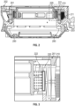
FIG. 2 is a side view of a bearing chamber with an annular oil distributor in accordance with embodiments; -
FIG. 3 is an enlarged view of the portion ofFIG. 2 encompassed by the dashed line inFIG 2 ; -
FIG. 4 is a perspective view of the annular oil distributor ofFIGS. 3 and4 provided as a squirrel cage in accordance with embodiments; -
FIG. 5 is a cutaway perspective view of the annular oil distribibutor ofFIG. 4 in accordance with embodiments; -
FIG. 6 is a flow diagram illustrating a method of manufacturing a bearing chamber in accordance with embodiments; -
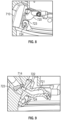
FIG. 7 is a perspective view of a bearing chamber and an interior surface of the bearing chamber with a terminal block in accordance with embodiments; -
FIG. 8 is a perspective view of the bearing chamber and the interior surface of the bearing chamber with the terminal block ofFIG. 7 and an oil nozzle in accordance with embodiments; -
FIG. 9 is a perspective view of the bearing chamber and the interior surface of the bearing chamber with the terminal block ofFIG. 7 and an inteiror of the oil nozzle ofFIG. 8 in accordance with embodiments; and -
FIG. 10 is a flow diagram illustrating a method of additively manufacturing a bearing chamber in accordance with embodiments. - These and other advantages and features will become more apparent from the following description taken in conjunction with the drawings.
- A detailed description of one or more embodiments of the disclosed apparatus and method are presented herein by way of exemplification and not limitation with reference to the Figures.
-
FIG. 1 schematically illustrates agas turbine engine 20. Thegas turbine engine 20 is disclosed herein as a two-spool turbofan that generally incorporates a fan section 22, acompressor section 24, acombustor section 26 and aturbine section 28. Alternative engines might include other systems or features. The fan section 22 drives air along a bypass flow path B in a bypass duct, while thecompressor section 24 drives air along a core flow path C for compression and communication into thecombustor section 26 and then expansion through theturbine section 28. Although depicted as a two-spool turbofan gas turbine engine in the disclosed non-limiting embodiment, it should be understood that the concepts described herein are not limited to use with two-spool turbofans as the teachings may be applied to other types of turbine engines including three-spool architectures. - The exemplary
gas turbine engine 20 generally includes alow speed spool 30 and ahigh speed spool 32 mounted for rotation about an engine central longitudinal axis A relative to an enginestatic structure 36 viaseveral bearing systems 38. It should be understood thatvarious bearing systems 38 at various locations may alternatively or additionally be provided, and the location ofbearing systems 38 may be varied as appropriate to the application. - The
low speed spool 30 generally includes aninner shaft 40 that interconnects afan 42, alow pressure compressor 44 and alow pressure turbine 46. Theinner shaft 40 is connected to thefan 42 through a speed change mechanism, which in exemplarygas turbine engine 20 is illustrated as a gearedarchitecture 48 to drive thefan 42 at a lower speed than thelow speed spool 30. Thehigh speed spool 32 includes anouter shaft 50 that interconnects ahigh pressure compressor 52 andhigh pressure turbine 54. Acombustor 56 is arranged in thegas turbine engine 20 between thehigh pressure compressor 52 and thehigh pressure turbine 54. The enginestatic structure 36 is arranged generally between thehigh pressure turbine 54 and thelow pressure turbine 46. The enginestatic structure 36 further supports the bearingsystems 38 in theturbine section 28. Theinner shaft 40 and theouter shaft 50 are concentric and rotate via bearingsystems 38 about the engine central longitudinal axis A which is collinear with their longitudinal axes. - The core airflow is compressed by the
low pressure compressor 44 and then thehigh pressure compressor 52, is mixed and burned with fuel in thecombustor 56 and is then expanded over thehigh pressure turbine 54 and thelow pressure turbine 46. The high andlow pressure turbines low speed spool 30 and thehigh speed spool 32, respectively, in response to the expansion. It will be appreciated that each of the positions of the fan section 22,compressor section 24,combustor section 26,turbine section 28, and fandrive gear system 48 may be varied. For example, gearedarchitecture 48 may be located aft of thecombustor section 26 or even aft of theturbine section 28, and the fan section 22 may be positioned forward or aft of the location of gearedarchitecture 48. - Within the
gas turbine engine 20, bearings are used to provide smooth relative rotation between the various shafts and non-rotating components and/or between two shafts which rotate at different speeds. An oil lubrication system can be provided that includes an oil pump, sometimes referred to as a main pump, and a network of conduits and nozzles to feed the bearings with oil. This oil is contained in bearing cavities, typically formed inside annular bearing chambers. A scavenge system having one or more scavenge lines extending from the bearing chambers and one or more scavenge pumps can be used to recover the oil, which can be in the form of an oil foam at that stage. Air/oil separation and filtering is typically provided for before returning the processed oil to the bearings. - In the bearing chambers, air and oil flows mix and generate a flow pattern about the engine central longitudinal axis A. The oil flow pattern generally operates as follows: Oil particles coalesce along internal bearing chamber partitions and form a liquid partition film which contains air bubbles. In the radial space between the rotating shaft and the liquid oil film, a mixture of air and dispersed oil particles swirl in a circumferential direction at a velocity greater than the liquid oil film flow along the partitions. As a result, the oil film flow is exposed to high shear stresses at the air/oil film interface. Film thickness and velocity distributions inside the bearing are driven by the magnitude of that interfacial shear and superimposed effects of gravitational forces.
- To achieve bearing chamber functionality, air and oil flows are discharged to an oil scavenge system which communicates with the oil sump and which is partially formed within the bearing chamber.
- As will be described below, an annular oil distributor of the
gas turbine engine 20 ofFIG. 1 is provided. The oil supply annulus can be integral to the rest of the bearing chamber body and is composed of network of channels (i.e., 50,000ths diameter). The channels may be fitted with converging/diverging breakout sections with the goal being to get better oil coverage in the bearing chamber. The oil supply annulus may have a built-in redundancy in a main artery. This can lead to a reduction in mass flow, but only a slight one. The oil supply annulus may have an outer manifold, an inner manifold (where the holes, which may have a conical opening, are located) that is disposed outstide of a rotating component and conical lines feeding oil from the outer manifold to the inner manifold. Oil is pressurized before it gets to the outer manifold. The nozzles of a conventional oil distribution system may not be replaced entirely by the annular oil distributor, or moved to other locations. A squirrel cage of the bearing chamber could serve as at least a part of the annular oil distributor. The squirrel cage is typically used for bearing support. In this case, channels for oil flow can be run through linear supports and the squirrel cage would be contiguous with the main body of the bearing chamber or provided with an interface. - With continued reference to
FIG. 1 and with additional reference toFIGS. 2-5 , an annular oil distributor (hereinafter referred to as an "oil distributor") 201 is provided for a component, such as abearing component 202 of thegas turbine engine 20 ofFIG. 1 . Theoil distributor 201 can be additively manufactured with the bearingchamber 202 and can have a complex geometry as such. - In any case, the
oil distributor 201 includes an outerannular manifold 210, which is integrally formed with aninterior surface 203 of the bearingchamber 202 and which is formed to define one or more firstinterior cavities 211 that are receptive of pressurized oil, and an innerannular manifold 220, which is formed to define a second interior cavity 221 and which includes an interior facingsurface 222. Theinterior facing surface 222 can be substantially cylindrical and is formed to define a lattice array of holes 223 that are respectively communicative with the second interior cavity 221. Theoil distributor 201 further includes one or more support struts 230 (seeFIG. 5 ) by which the innerannular manifold 220 is supported within the outerannular manifold 210. Each of the one or more support struts 230 is formed to defineinterior lines 231 by which the pressurized oil flows from the one or more firstinterior cavities 211 to the second interior cavity 221 and to the holes 223 via the second interior cavity 221. In addition, each of the one or more support struts 230 has a narrowingtaper 232 with decreasing radial distance D (seeFIG. 5 ) from the innerannular manifold 220. - In accordance with embodiments and as shown in
FIGS. 4 and 5 , the outerannular manifold 210 can include or be provided as asquirrel cage 401 of the bearingchamber 202. In these or other cases, the outerannular manifold 210 can be provided as anupper manifold portion 410, alower manifold portion 420 to which the one or more support struts 230 can be connected and an annular array oflinear supports 430. AlthoughFIG. 5 illustrates these features as solid, it is to be understood that theupper manifold portion 410, thelower maniold portion 420 and each of thelinear supports 430 can be formed to including a hollow interior defining the one or more firstinterior cavities 211. - As such, pressurized oil can be received in the one or more first
interior cavities 211 of theupper manifold portion 410, thelower manifold portion 420 and the annular array oflinear supports 430 and then can be transferred to the second interior cavity 221 of the innerannular manifold 220 via theinterior lines 231 of the one or more support struts 230. The pressurized oil can then flow out of the second interior cavity 221 via the holes 223 to lubricate and cool thebearing chamber 202. - With continued reference to
FIG. 2 , the bearingchamber 202 can include theoil distributor 201 as described above as well as one ormore nozzles 250 in a hybrid configuration. In these or other cases, theoil distributor 201 serves to lubricate and cool one section of the bearing chamber 202 (i.e., the upper section as shown inFIG. 2 ) while the one ormore nozzle 250 serve to lubricate and cool another section or a different surface of the bearing chamber 202 (i.e., portions of the lower section as shown inFIG. 2 ). The presence or each feature type in the hybrid configuration allows for weight reduction in some cases as well as substantial oil distribution by theoil distributor 201 and targeted oil distribution by the one ormore nozzles 250. - With reference to
FIG. 6 , amethod 600 of manufacturing a bearing chamber, such as the bearingchamber 202 described above, is provided. Themethod 600 includes additively manufacturing the bearing chamber (block 601) and additively manufacturing an oil distributor integrally with the bearing chamber (block 602) where the oil distributor is provided as theoil distributor 201 described above. Themethod 600 can further include optionally additively manufacturing one or more oil nozzles with the bearing chamber (block 603). - With reference to
FIGS. 7-9 , a bearingchamber 701 is provided and includes aninterior surface 710, which can be additively manufactured, and anoil nozzle 720 and/or theoil distributor 201 as described above, both of which can also be additively manufactured. Theinterior surface 710 includes aterminal block 711 that is formed to define akeyway 712 and aconduit 713. Theconduit 713 extends through a body of the bearingchamber 701 and terminates at aterminus 714 at thekeyway 712. Theoil nozzle 720 is formed to define aninternal channel 721 with an opening 722 (i.e., theinternal channel 211 of FIG. 3A) and includes abase 723, with theoil distributor 201 having similar features. Both thekeyway 712 and the base 723 can be elongate. In any case, thebase 723 is tightly fittable in thekeyway 712. The base 723 can also include afastening point 724, at which thebase 723 is fastened to theterminal block 711 at thekeyway 712. - When the
base 723 is tightly fit in thekeyway 712 as shown inFIGS. 8 and 9 , theopening 722 of theinternal channel 721 sits flush against theterminus 714 of theconduit 713 whereby theinternal channel 721 is fluidly communicative with theconduit 713. As such, oil or other fluids directed into and through theconduit 713 enter and flow through theinternal channel 721. In addition, when thebase 722 is tightly fit in thekeyway 712, an orientation of thekeyway 712 and a configuration of theoil nozzle 720/oil distributor 201 are cooperatively established to aim theoil nozzle 720/oil distributor 201 at one or more predefined targets within the bearingchamber 701. In this way, the orientation of thekeyway 712 and the configuration of theoil nozzle 720/oil distributor 201 work cooperatively to aim a flow of oil or other fluids passing through theinternal channel 721 toward the one or more predefined targets. - With reference to
FIG. 10 , a method of additively manufacturing a bearing chamber, such as the bearingchamber 701 ofFIGS. 7-9 , is provided. The method includes additively manufacturing an interior surface of the bearing chamber to include a terminal block defining a keyway and a conduit terminating at the keyway (block 1001) and forming an oil nozzle or distributor defining an internal channel and including a base (block 1002). The method further includes tightly fitting the base in the keyway such that the internal channel is fluidly communicative with the conduit (block 1003) and establishing an orientation of the keyway and a configuration of the oil nozzle or distributor to aim the oil nozzle or distributor at one or more predefined targets within the bearing chamber (block 1004). - In accordance with embodiments, in
block 1004, the establishing of the orientation of the keyway can be set first and the configuration of the oil nozzle/distributor can be based on the orientating of the keyway or the establishing of the the configuration of the oil nozzle/distributor can be set first and the orientation of the keyway can be based on the configuration of the oil nozzle/distributor. - Benefits of the features described herein are the provision of an oil distributor that can provide lubrication and cooling for a bearing chamber. The oil distributor can be formed integrally with the bearing chamber through the use of additive manufacturing that allows for complex geometries and fluid connnections. In some cases, the oil distributor can be paired with one or more nozzles for additional oil distribution in a hybrid configuration that can allow for substantial oil distribution by the oil distributor and targeted oil distribution by the one or more nozzles.
- The term "about" is intended to include the degree of error associated with measurement of the particular quantity based upon the equipment available at the time of filing the application.
- The terminology used herein is for the purpose of describing particular embodiments only and is not intended to be limiting of the present disclosure. As used herein, the singular forms "a", "an" and "the" are intended to include the plural forms as well, unless the context clearly indicates otherwise. It will be further understood that the terms "comprises" and/or "comprising," when used in this specification, specify the presence of stated features, integers, steps, operations, elements, and/or components, but do not preclude the presence or addition of one or more other features, integers, steps, operations, element components, and/or groups thereof.
- While the present disclosure has been described with reference to an exemplary embodiment or embodiments, it will be understood by those skilled in the art that various changes may be made and equivalents may be substituted for elements thereof without departing from the scope of the present disclosure. In addition, many modifications may be made to adapt a particular situation or material to the teachings of the present disclosure without departing from the essential scope thereof. Therefore, it is intended that the present disclosure not be limited to the particular embodiment disclosed as the best mode contemplated for carrying out this present disclosure, but that the present disclosure will include all embodiments falling within the scope of the claims.
Claims (15)
- An oil distributor (201) for a bearing chamber (202), the oil distributor (201) comprising:an outer annular manifold (210), which is integrally formed with an interior surface (203) of the bearing chamber (202) and which defines a first interior cavity (211) receptive of pressurized oil;an inner annular manifold (220), which defines a second interior cavity (221) and comprises an interior facing surface (222) defining holes (223) respectively communicative with the second interior cavity (221); andone or more support struts (230) by which the inner annular manifold (220) is supported within the outer annular manifold (210),each of the one or more support struts (230) defining interior lines (231) by which the pressurized oil flows from the first interior cavity (211) to the second interior cavity (221) and to the holes (223).
- The oil distributor (201) according to claim 1, wherein the oil distributor (201) is additively manufactured with the bearing chamber (202).
- The oil distributor (201) according to claim 1 or 2, wherein the outer annular manifold (210) comprises a squirrel cage (401) with linear supports (430) through which the pressurized oil is flowable.
- The oil distributor (201) according to claim 1, 2 or 3, wherein each of the one or more support struts (230) has a narrowing taper (232) with decreasing radial distance from the inner annular manifold (220).
- The oil distributor (201) according to any preceding claim, wherein the interior facing surface (222) is cylindrical and the holes (223) are arrayed in a lattice along the interior facing surface (222).
- A bearing chamber (202), comprising:one or more nozzles (250); andthe oil distributor (201) of claim 1.
- The bearing chamber (202) according to claim 6, wherein each of the one or more nozzles (250) is configured to output oil toward a surface of the bearing chamber (202).
- The bearing chamber (202) according to claim 6, wherein the oil distributor (201) and each of the one or more nozzles (250) are configured to output oil toward a different surface of the bearing chamber (202).
- The bearing chamber (202) according to claim 6, 7 or 8, wherein the oil distributor (201) is additively manufactured with the bearing chamber (202).
- The bearing chamber (202) according to any of claims 6 to 9, wherein the outer annular manifold (210) comprises a squirrel cage (401) with linear supports (430) through which the pressurized oil is flowable.
- The bearing chamber (202) according to any of claims 6 to 10, wherein:each of the one or more support struts (230) has a narrowing taper (232) with decreasing radial distance from the inner annular manifold (220); and/orthe interior facing surface (222) is cylindrical and the holes (223) are arrayed in a lattice along the interior facing surface (222).
- A method of manufacturing a bearing chamber (202), the method comprising:additively manufacturing the bearing chamber (202); andadditively manufacturing an oil distributor (201) integrally with the bearing chamber (202), the oil distributor (201) comprising:an outer annular manifold (210), which is integrally formed with an interior surface (203) of the bearing chamber (202) and which defines a first interior cavity (211) receptive of pressurized oil;an inner annular manifold (220), which defines a second interior cavity (221) and comprises an interior facing surface (222) defining holes (223) respectively communicative with the second interior cavity (221); andone or more support struts (230) by which the inner annular manifold (220) is supported within the outer annular manifold (210),each of the one or more support struts (230) defining interior lines (231) by which the pressurized oil flows from the first interior cavity (211) to the second interior cavity (221) and to the holes (223).
- The method according to claim 12, further comprising additively manufacturing one or more nozzles (250) integrally with the bearing chamber (202).
- The method according to claim 13, wherein each of the one or more nozzles (250) is configured to output oil toward a surface of the bearing chamber (202).
- The method according to claim 13, wherein the oil distributor (201) and each of the one or more nozzles (250) are configured to output oil toward different surfaces of the bearing chamber (202).
Applications Claiming Priority (1)
| Application Number | Priority Date | Filing Date | Title |
|---|---|---|---|
| US202263423381P | 2022-11-07 | 2022-11-07 |
Publications (1)
| Publication Number | Publication Date |
|---|---|
| EP4365415A1 true EP4365415A1 (en) | 2024-05-08 |
Family
ID=88731466
Family Applications (1)
| Application Number | Title | Priority Date | Filing Date |
|---|---|---|---|
| EP23208214.9A Pending EP4365415A1 (en) | 2022-11-07 | 2023-11-07 | Annular oil distributor for bearing chamber |
Country Status (2)
| Country | Link |
|---|---|
| US (2) | US12473842B2 (en) |
| EP (1) | EP4365415A1 (en) |
Citations (6)
| Publication number | Priority date | Publication date | Assignee | Title |
|---|---|---|---|---|
| EP2940324B1 (en) * | 2014-04-29 | 2017-08-02 | MTU Aero Engines GmbH | Bearing cage and bearing device having such a bearing cage and method for producing, repairing and/or replacing such a bearing cage |
| DE102018202494A1 (en) * | 2018-02-19 | 2019-08-22 | MTU Aero Engines AG | STORAGE CHAMBER HOUSING FOR A FLOW MACHINE |
| US20200080445A1 (en) * | 2018-09-10 | 2020-03-12 | United Technologies Corporation | Reduced axial space self-pressurizing damper |
| US20210062679A1 (en) * | 2018-03-23 | 2021-03-04 | Safran Aircraft Engines | Turbojet bearing support produced by additive manufacturing |
| US20220235672A1 (en) * | 2019-06-26 | 2022-07-28 | Safran Aircraft Engines | Turbomachine output bearing support |
| EP4102033A1 (en) * | 2021-06-11 | 2022-12-14 | MTU Aero Engines AG | Bearing chamber casing for a turbomachine |
-
2023
- 2023-11-06 US US18/387,365 patent/US12473842B2/en active Active
- 2023-11-07 EP EP23208214.9A patent/EP4365415A1/en active Pending
-
2025
- 2025-10-27 US US19/370,077 patent/US20260049564A1/en active Pending
Patent Citations (6)
| Publication number | Priority date | Publication date | Assignee | Title |
|---|---|---|---|---|
| EP2940324B1 (en) * | 2014-04-29 | 2017-08-02 | MTU Aero Engines GmbH | Bearing cage and bearing device having such a bearing cage and method for producing, repairing and/or replacing such a bearing cage |
| DE102018202494A1 (en) * | 2018-02-19 | 2019-08-22 | MTU Aero Engines AG | STORAGE CHAMBER HOUSING FOR A FLOW MACHINE |
| US20210062679A1 (en) * | 2018-03-23 | 2021-03-04 | Safran Aircraft Engines | Turbojet bearing support produced by additive manufacturing |
| US20200080445A1 (en) * | 2018-09-10 | 2020-03-12 | United Technologies Corporation | Reduced axial space self-pressurizing damper |
| US20220235672A1 (en) * | 2019-06-26 | 2022-07-28 | Safran Aircraft Engines | Turbomachine output bearing support |
| EP4102033A1 (en) * | 2021-06-11 | 2022-12-14 | MTU Aero Engines AG | Bearing chamber casing for a turbomachine |
Also Published As
| Publication number | Publication date |
|---|---|
| US20240151271A1 (en) | 2024-05-09 |
| US12473842B2 (en) | 2025-11-18 |
| US20260049564A1 (en) | 2026-02-19 |
Similar Documents
| Publication | Publication Date | Title |
|---|---|---|
| EP2855882B1 (en) | Lubrication arrangement for a gas turbine engine gear assembly | |
| US7296398B2 (en) | Counter-rotating turbine engine and method of assembling same | |
| US10352195B2 (en) | Non-contacting seals for geared gas turbine engine bearing compartments | |
| EP3693651B1 (en) | Non-uniform spray pattern oil delivery nozzle | |
| EP2058541B1 (en) | Method and apparatus for fan shaft bearing lubrication | |
| EP3772571B1 (en) | Ducted oil scoop for gas turbine engine | |
| EP3084180B1 (en) | Transfer bearing for geared turbofan | |
| EP3708794B1 (en) | Dual radial scoop oil delivery system | |
| US11970981B2 (en) | Planetary gearbox | |
| EP4365415A1 (en) | Annular oil distributor for bearing chamber | |
| US20180223690A1 (en) | Non-contacting seals for geared gas turbine engine bearing compartments | |
| US12571330B2 (en) | Oil nozzle for bearing chamber | |
| EP3957832B1 (en) | Integral gear support and bearing damper pedestal of a gas turbine engine | |
| EP3933170B1 (en) | Mid mount sleeve arrangement | |
| EP3971389B1 (en) | Anti-vortex tube retaining ring and bore basket | |
| EP3748133B1 (en) | Fatigue resistant blade outer air seal | |
| US12546234B2 (en) | Bearing chamber with thermal heat exchange fins | |
| US20240151155A1 (en) | Bearing chamber with mapped thermal heat exchange fins | |
| EP4365412A1 (en) | Oil passage built into bearing compartment spring | |
| EP3372793B1 (en) | Non-contacting seals for geared gas turbine engine bearing compartments | |
| US12421872B2 (en) | Spring damping for bearing compartment | |
| US20240131588A1 (en) | Hybrid bearing forged flange |
Legal Events
| Date | Code | Title | Description |
|---|---|---|---|
| PUAI | Public reference made under article 153(3) epc to a published international application that has entered the european phase |
Free format text: ORIGINAL CODE: 0009012 |
|
| STAA | Information on the status of an ep patent application or granted ep patent |
Free format text: STATUS: THE APPLICATION HAS BEEN PUBLISHED |
|
| AK | Designated contracting states |
Kind code of ref document: A1 Designated state(s): AL AT BE BG CH CY CZ DE DK EE ES FI FR GB GR HR HU IE IS IT LI LT LU LV MC ME MK MT NL NO PL PT RO RS SE SI SK SM TR |
|
| STAA | Information on the status of an ep patent application or granted ep patent |
Free format text: STATUS: REQUEST FOR EXAMINATION WAS MADE |
|
| 17P | Request for examination filed |
Effective date: 20241108 |
|
| RBV | Designated contracting states (corrected) |
Designated state(s): AL AT BE BG CH CY CZ DE DK EE ES FI FR GB GR HR HU IE IS IT LI LT LU LV MC ME MK MT NL NO PL PT RO RS SE SI SK SM TR |