EP4365412A1 - Oil passage built into bearing compartment spring - Google Patents
Oil passage built into bearing compartment spring Download PDFInfo
- Publication number
- EP4365412A1 EP4365412A1 EP23208004.4A EP23208004A EP4365412A1 EP 4365412 A1 EP4365412 A1 EP 4365412A1 EP 23208004 A EP23208004 A EP 23208004A EP 4365412 A1 EP4365412 A1 EP 4365412A1
- Authority
- EP
- European Patent Office
- Prior art keywords
- spring
- struts
- oil passage
- bearing compartment
- housing
- Prior art date
- Legal status (The legal status is an assumption and is not a legal conclusion. Google has not performed a legal analysis and makes no representation as to the accuracy of the status listed.)
- Pending
Links
Images



Classifications
-
- F—MECHANICAL ENGINEERING; LIGHTING; HEATING; WEAPONS; BLASTING
- F01—MACHINES OR ENGINES IN GENERAL; ENGINE PLANTS IN GENERAL; STEAM ENGINES
- F01D—NON-POSITIVE DISPLACEMENT MACHINES OR ENGINES, e.g. STEAM TURBINES
- F01D25/00—Component parts, details, or accessories, not provided for in, or of interest apart from, other groups
- F01D25/16—Arrangement of bearings; Supporting or mounting bearings in casings
- F01D25/162—Bearing supports
- F01D25/164—Flexible supports; Vibration damping means associated with the bearing
-
- B—PERFORMING OPERATIONS; TRANSPORTING
- B22—CASTING; POWDER METALLURGY
- B22F—WORKING METALLIC POWDER; MANUFACTURE OF ARTICLES FROM METALLIC POWDER; MAKING METALLIC POWDER; APPARATUS OR DEVICES SPECIALLY ADAPTED FOR METALLIC POWDER
- B22F10/00—Additive manufacturing of workpieces or articles from metallic powder
- B22F10/30—Process control
- B22F10/38—Process control to achieve specific product aspects, e.g. surface smoothness, density, porosity or hollow structures
- B22F10/385—Overhang structures
-
- B—PERFORMING OPERATIONS; TRANSPORTING
- B33—ADDITIVE MANUFACTURING TECHNOLOGY
- B33Y—ADDITIVE MANUFACTURING, i.e. MANUFACTURING OF THREE-DIMENSIONAL [3D] OBJECTS BY ADDITIVE DEPOSITION, ADDITIVE AGGLOMERATION OR ADDITIVE LAYERING, e.g. BY 3D PRINTING, STEREOLITHOGRAPHY OR SELECTIVE LASER SINTERING
- B33Y10/00—Processes of additive manufacturing
-
- B—PERFORMING OPERATIONS; TRANSPORTING
- B33—ADDITIVE MANUFACTURING TECHNOLOGY
- B33Y—ADDITIVE MANUFACTURING, i.e. MANUFACTURING OF THREE-DIMENSIONAL [3D] OBJECTS BY ADDITIVE DEPOSITION, ADDITIVE AGGLOMERATION OR ADDITIVE LAYERING, e.g. BY 3D PRINTING, STEREOLITHOGRAPHY OR SELECTIVE LASER SINTERING
- B33Y80/00—Products made by additive manufacturing
-
- F—MECHANICAL ENGINEERING; LIGHTING; HEATING; WEAPONS; BLASTING
- F01—MACHINES OR ENGINES IN GENERAL; ENGINE PLANTS IN GENERAL; STEAM ENGINES
- F01D—NON-POSITIVE DISPLACEMENT MACHINES OR ENGINES, e.g. STEAM TURBINES
- F01D25/00—Component parts, details, or accessories, not provided for in, or of interest apart from, other groups
- F01D25/18—Lubricating arrangements
-
- F—MECHANICAL ENGINEERING; LIGHTING; HEATING; WEAPONS; BLASTING
- F01—MACHINES OR ENGINES IN GENERAL; ENGINE PLANTS IN GENERAL; STEAM ENGINES
- F01D—NON-POSITIVE DISPLACEMENT MACHINES OR ENGINES, e.g. STEAM TURBINES
- F01D25/00—Component parts, details, or accessories, not provided for in, or of interest apart from, other groups
- F01D25/28—Supporting or mounting arrangements, e.g. for turbine casing
- F01D25/285—Temporary support structures, e.g. for testing, assembling, installing, repairing; Assembly methods using such structures
-
- F—MECHANICAL ENGINEERING; LIGHTING; HEATING; WEAPONS; BLASTING
- F02—COMBUSTION ENGINES; HOT-GAS OR COMBUSTION-PRODUCT ENGINE PLANTS
- F02C—GAS-TURBINE PLANTS; AIR INTAKES FOR JET-PROPULSION PLANTS; CONTROLLING FUEL SUPPLY IN AIR-BREATHING JET-PROPULSION PLANTS
- F02C7/00—Features, components parts, details or accessories, not provided for in, or of interest apart form groups F02C1/00 - F02C6/00; Air intakes for jet-propulsion plants
- F02C7/06—Arrangements of bearings; Lubricating
-
- B—PERFORMING OPERATIONS; TRANSPORTING
- B22—CASTING; POWDER METALLURGY
- B22F—WORKING METALLIC POWDER; MANUFACTURE OF ARTICLES FROM METALLIC POWDER; MAKING METALLIC POWDER; APPARATUS OR DEVICES SPECIALLY ADAPTED FOR METALLIC POWDER
- B22F10/00—Additive manufacturing of workpieces or articles from metallic powder
- B22F10/20—Direct sintering or melting
- B22F10/28—Powder bed fusion, e.g. selective laser melting [SLM] or electron beam melting [EBM]
-
- F—MECHANICAL ENGINEERING; LIGHTING; HEATING; WEAPONS; BLASTING
- F05—INDEXING SCHEMES RELATING TO ENGINES OR PUMPS IN VARIOUS SUBCLASSES OF CLASSES F01-F04
- F05D—INDEXING SCHEME FOR ASPECTS RELATING TO NON-POSITIVE-DISPLACEMENT MACHINES OR ENGINES, GAS-TURBINES OR JET-PROPULSION PLANTS
- F05D2230/00—Manufacture
- F05D2230/30—Manufacture with deposition of material
-
- F—MECHANICAL ENGINEERING; LIGHTING; HEATING; WEAPONS; BLASTING
- F05—INDEXING SCHEMES RELATING TO ENGINES OR PUMPS IN VARIOUS SUBCLASSES OF CLASSES F01-F04
- F05D—INDEXING SCHEME FOR ASPECTS RELATING TO NON-POSITIVE-DISPLACEMENT MACHINES OR ENGINES, GAS-TURBINES OR JET-PROPULSION PLANTS
- F05D2230/00—Manufacture
- F05D2230/30—Manufacture with deposition of material
- F05D2230/31—Layer deposition
-
- F—MECHANICAL ENGINEERING; LIGHTING; HEATING; WEAPONS; BLASTING
- F05—INDEXING SCHEMES RELATING TO ENGINES OR PUMPS IN VARIOUS SUBCLASSES OF CLASSES F01-F04
- F05D—INDEXING SCHEME FOR ASPECTS RELATING TO NON-POSITIVE-DISPLACEMENT MACHINES OR ENGINES, GAS-TURBINES OR JET-PROPULSION PLANTS
- F05D2240/00—Components
- F05D2240/10—Stators
- F05D2240/14—Casings or housings protecting or supporting assemblies within
Definitions
- Exemplary embodiments of the present disclosure relate generally to gas turbine engines and, in one embodiment, to an oil passage built into a spring in a bearing compartment of a gas turbine engine.
- a gas turbine engine air is compressed in a compressor and compressor air is then mixed with fuel and combusted in a combustor to produce a high-temperature and high-pressure working fluid.
- This working fluid is directed into a turbine in which the working fluid is expanded to generate power.
- the generated power drives the rotation of a rotor within the turbine through aerodynamic interactions between the working fluid and turbine blades or airfoils.
- the rotor can be used to drive rotation of a propeller/fan or to produce electricity in a generator.
- Certain parts, such as a bearing compartment, in a gas turbine engine need a supply of oil for cooling and/or lubrication.
- oil is supplied via tubes that are separate from other components.
- tubes can be added to reach oil nozzles. This can constrain oil nozzle placement and make assembly difficult where multiple tubes must be routed around other components.
- a bearing compartment including a housing and a spring integrally formed with the housing.
- An oil passage is internally fabricated within the housing and the oil passage extends into the spring.
- the spring can be a squirrel cage spring, and a centerline of struts of the spring can extend axially in parallel to an axis of rotation defined within a central cavity of the bearing compartment.
- the spring can include an annular support member and a plurality of struts, and the oil passage can be fabricated within the annular support member and through two or more of the struts.
- the oil passage within the annular support member can form a manifold to distribute oil to the two or more of the struts.
- the annular support member can be an upper support
- the spring can include a lower support
- the struts can extend between the upper support and the lower support.
- the lower support can include a lower manifold in fluid communication with the manifold of the upper support through the two or more of the struts.
- the bearing compartment can include an oil nozzle in fluid communication with the oil passage within the spring.
- a gas turbine engine can include a compressor section, a turbine section, a shaft coupled to the compressor section and the turbine section, and a bearing system.
- the bearing system is configured to support rotation of the shaft.
- the bearing system can include a housing integrally formed with a spring.
- An oil passage can be internally fabricated within the housing, and the oil passage can extend into the spring.
- a method of manufacturing a bearing compartment includes additively manufacturing a lower portion of a housing of the bearing compartment including a spring radially inward of the housing.
- the method also includes additively manufacturing a plurality of struts of the spring to extend axially within the housing.
- the method further includes additively manufacturing an upper portion of the housing extending from the lower portion.
- the upper portion includes an overhang region that is integrally formed with the spring.
- An oil passage is internally fabricated within the housing and the oil passage extends into the spring.
- the spring can include an annular support member and the struts
- the method can include fabricating the oil passage within the annular support member and through two or more of the struts, and the oil passage within the annular support member can form a manifold to distribute oil to the two or more of the struts.
- the method can include establishing fluid communication between an oil nozzle and the oil passage within the spring.
- FIG. 1 schematically illustrates a gas turbine engine 20.
- the gas turbine engine 20 is disclosed herein as a two-spool turbofan that generally incorporates a fan section 22, a compressor section 24, a combustor section 26 and a turbine section 28.
- Alternative engines might include other systems or features.
- the fan section 22 drives air along a bypass flow path B in a bypass duct, while the compressor section 24 drives air along a core flow path C for compression and communication into the combustor section 26 and then expansion through the turbine section 28.
- the exemplary gas turbine engine 20 generally includes a low speed spool 30 and a high speed spool 32 mounted for rotation about an engine central longitudinal axis A relative to an engine static structure 36 via several bearing systems 38. It should be understood that various bearing systems 38 at various locations may alternatively or additionally be provided, and the location of bearing systems 38 may be varied as appropriate to the application.
- the low speed spool 30 generally includes an inner shaft 40 that interconnects a fan 42, a low pressure compressor 44 and a low pressure turbine 46.
- the inner shaft 40 is connected to the fan 42 through a speed change mechanism, which in exemplary gas turbine engine 20 is illustrated as a geared architecture 48 to drive the fan 42 at a lower speed than the low speed spool 30.
- the high speed spool 32 includes an outer shaft 50 that interconnects a high pressure compressor 52 and high pressure turbine 54.
- a combustor 56 is arranged in the gas turbine engine 20 between the high pressure compressor 52 and the high pressure turbine 54.
- the engine static structure 36 is arranged generally between the high pressure turbine 54 and the low pressure turbine 46.
- the engine static structure 36 further supports the bearing systems 38 in the turbine section 28.
- the inner shaft 40 and the outer shaft 50 are concentric and rotate via bearing systems 38 about the engine central longitudinal axis A which is collinear with their longitudinal axes.
- the core airflow is compressed by the low pressure compressor 44 and then the high pressure compressor 52, is mixed and burned with fuel in the combustor 56 and is then expanded over the high pressure turbine 54 and the low pressure turbine 46.
- the high and low pressure turbines 54 and 46 rotationally drive the low speed spool 30 and the high speed spool 32, respectively, in response to the expansion.
- geared architecture 48 may be located aft of the combustor section 26 or even aft of the turbine section 28, and the fan section 22 may be positioned forward or aft of the location of geared architecture 48.
- the gas turbine engine 20 in one example is a high-bypass geared aircraft engine.
- the gas turbine engine 20 bypass ratio is greater than about six (6), with an example embodiment being greater than about ten (10)
- the geared architecture 48 is an epicyclic gear train, such as a planetary gear system or other gear system, with a gear reduction ratio of greater than about 2.3
- the low pressure turbine 46 has a pressure ratio that is greater than about five.
- the gas turbine engine 20 bypass ratio is greater than about ten (10:1)
- the fan diameter is significantly larger than that of the low pressure compressor 44
- the low pressure turbine 46 has a pressure ratio that is greater than about five 5:1.
- Low pressure turbine 46 pressure ratio is pressure measured prior to inlet of low pressure turbine 46 as related to the pressure at the outlet of the low pressure turbine 46 prior to an exhaust nozzle.
- the geared architecture 48 may be an epicycle gear train, such as a planetary gear system or other gear system, with a gear reduction ratio of greater than about 2.3:1. It should be understood, however, that the above parameters are only exemplary of one embodiment of a geared architecture engine and that the present disclosure is applicable to other gas turbine engines including direct drive turbofans.
- the fan section 22 of the gas turbine engine 20 is designed for a particular flight condition--typically cruise at about 0.8 Mach and about 35,000 feet (10,688 meters).
- 'TSFC' Thrust Specific Fuel Consumption
- Low fan pressure ratio is the pressure ratio across the fan blade alone, without a Fan Exit Guide Vane (“FEGV”) system.
- the low fan pressure ratio as disclosed herein according to one non-limiting embodiment is less than about 1.45.
- Low corrected fan tip speed is the actual fan tip speed in ft/sec divided by an industry standard temperature correction of [(Tram °R)/(518.7 °R)] 0.5 .
- the "Low corrected fan tip speed” as disclosed herein according to one non-limiting embodiment is less than about 1150 ft/second (350.5 m/sec).
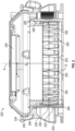
- a bearing compartment 202 of the gas turbine engine 20 of FIG. 1 can be additively manufactured and include a number of features with a complex geometry.
- the bearing compartment 202 can be part of the bearing systems 38 to support rotation of one or more shafts, such as the inner shaft 40 or the outer shaft 50.
- the bearing compartment 202 includes a spring 220 integrally formed with a housing 230 of the bearing compartment 202.
- the housing 230 can include a lower portion 232 and an upper portion 234. Rather than separately manufacturing the lower portion 232 and upper portion 234, the housing 230 can be monolithically formed through an additive manufacturing process.
- the upper portion 234 of the housing 230 can include an overhang region 236 that is supported by the spring 220 during an additive manufacturing build process.
- the bearing compartment 202 can be manufactured using a powder bed fusion process, e.g., laser or electron beam based, to progressively build the housing 230 from the lower portion 232 to the upper portion 234 while also building the spring 220 within an interior of the housing 230.
- Forming the spring 220 integrally with the housing 230 can enhance structural stability and prevent the spring 220 from rotating relative to the housing 230 during assembly of the bearing compartment 202.
- the spring 220 can include a plurality of struts 222 that extend axially within the housing 230.
- the spring 220 can be a squirrel cage spring, and a centerline D of the struts 222 can extend axially in parallel to an axis of rotation (e.g., engine central longitudinal axis A) defined within a central cavity 240 of the bearing compartment 202.
- the struts 222 can extend between a first annular support member 224 (e.g., a lower support) and a second annular support member 226 (e.g., an upper support).
- the spring 220 can include an oil passage 250 internally fabricated within one or more struts 222 of the spring 220.
- the oil passage 250 can provide a path for oil flow through the spring 220 to deliver oil at or below the lower support 224.
- the oil passage 250 can be fabricated within the upper support 226 and through two or more of the struts 222.
- the oil passage 250 within the upper support can form a manifold 252 to distribute oil to two or more of the struts 222. Oil can be delivered directly to an oil nozzle or be routed through one or more components of the bearing compartment 202 before reaching an oil nozzle after flowing through the oil passage 250.
- all of the struts 222 can include the oil passage 250.
- a subset of the struts 222 can include the oil passage 250, such as every other strut 222, every third strut 222, every fourth strut 222, etc.
- the number of struts 222 that incorporate the oil passage 250 can be determined by an oil flow and pressure analysis. Incorporating the oil passage 250 in two or more of the struts 222 can provide a substantially symmetrical design of the spring 220 and multiple distribution paths.
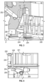
- FIG. 3 depicts an example of an oil passage 250 that can be formed in housing 230 and a strut 222 of spring 220.
- the oil passage 250 can be internally fabricated within the housing 230, and the oil passage 250 extends into the spring 220, for instance, through upper support 226.
- the oil passage 250 can be a direct flow-through passage that enters at the upper support 226, flows through the strut 222, and exits through a port 254 of the lower support 224.
- the manifold 252 of FIG. 2 may be omitted.
- There can be multiple separate instances of the oil passage 250 formed between the housing 230 can separate struts 222, where the oil passages 250 may not be in fluid communication with each other.
- the path of the oil passage 250 within the housing 230 can be determined based on structural analysis and flow dynamics of the oil.
- Routing the oil passage 250 through the spring 220 can allow a flow of oil to reach the port 254, where an oil nozzle may be located or a path may be defined to reach a location further away from the spring 220. This can prevent the need for separate tubes to be routed within the bearing compartment 202 and allow oil to reach locations that may not otherwise be accessible.
- the housing 230 may be manufactured with a support structure 290 that is later machined away and thus prevents the oil passage 250 from being routed down through the housing 230 to the port 254.
- FIG. 4 depicts an example of an oil passage 250 through a spring 220 in accordance with embodiments.
- the spring 220 may be shrouded by a cover 221.
- the oil passage 250 can pass through housing 230 and the spring 220.
- the oil passage 250 can exit the spring 220 at port 254 and continue within another component 256 of the bearing compartment 202 of FIG. 2 to one or more oil nozzles 260.
- oil can be distributed to locations below the spring 220 without the need for separate tubes within the bearing compartment 202.
- FIG. 5 depicts additional aspects of a portion 500 of the spring 220 of FIG. 2 to better illustrate a strut 222 between the first annular support member 224 and the second annular support member 226.
- the body of the strut 222 can be canted such that the cross-sectional area of the strut 222 decreases when transitioning from the first annular support member 224 through a lower strut portion 302 to a central strut portion 304.
- the cross-sectional area of the strut 222 can increase when transitioning from the central strut portion 304 through an upper strut portion 306 to the second annular support member 226.
- the first annular support member 224 can also include a channel 258 that may extend laterally from the strut 222 to provide oil distribution to a location radially inward of the strut 222.
- the channel 258 may extend between multiple struts 222.
- FIG. 6 depicts an alternate spring strut with upper and lower oil manifolds in accordance with embodiments.
- the strut 222 does not have the oil passage 250 formed within the strut 222.
- the strut 222 of FIG. 6 can be a support strut of the spring 220 that is formed between two of the struts 222 of FIG. 5 such that some struts 222 allow oil to flow through and others do not.
- the upper support 226 can include the manifold 252 and/or the lower support 224 can include a lower manifold 262 that allows oil circulation above and/or below the strut 222 of FIG. 6 within the spring 220 of FIG. 2 .
- a bearing chamber 701 is provided and includes an interior surface 710, which can be additively manufactured, and an oil nozzle 720, which can also be additively manufactured.
- the bearing chamber 701 can be a portion of the bearing compartment 202 of FIG. 2 .
- the interior surface 710 includes a terminal block 711 that is formed to define a keyway 712 and a conduit 713.
- the conduit 713 can extend through a body of the bearing chamber 701 and terminates at a terminus 714 at the keyway 712.
- the conduit 713 can be in fluid communication with the port 254.
- the oil nozzle 720 is an example of oil nozzle 260 of FIG. 4 .
- the oil nozzle 720 can be formed to define an internal channel 721 with an opening 722 and includes a base 723. Both the keyway 712 and the base 723 can be elongate. In any case, the base 723 is tightly fittable in the keyway 712. The base 723 can also include a fastening point 724, at which the base 723 is fastened to the terminal block 711 at the keyway 712.
- the opening 722 of the internal channel 721 sits flush against the terminus 714 of the conduit 713 whereby the internal channel 721 is fluidly communicative with the conduit 713.
- oil or other fluids directed into and through the conduit 713 enter and flow through the internal channel 721.
- an orientation of the keyway 712 and a configuration of the oil nozzle 720 are cooperatively established to aim the oil nozzle 720 at one or more predefined targets within the bearing chamber 701. In this way, the orientation of the keyway 712 and the configuration of the oil nozzle 720 work cooperatively to aim a flow of oil or other fluids passing through the internal channel 721 toward the one or more predefined targets.
- a method 1000 of manufacturing a bearing compartment such as the bearing compartment 202 described above, is provided.
- the method 1000 includes additively manufacturing a lower portion 232 of a housing 230 of the bearing compartment 202 including a spring 220 radially inward of the housing 230.
- the method 1000 includes additively manufacturing a plurality of struts 222 of the spring 220 to extend axially within the housing 230.
- the method 1000 includes additively manufacturing an upper portion 234 of the housing 230 extending from the lower portion 232, where the upper portion 234 includes an overhang region 236 that is integrally formed with the spring 220.
- An oil passage 250 can be internally fabricated within the housing 230, and the oil passage 250 extends into the spring 220.
- the spring 220 is additively manufactured as a squirrel cage spring, and a centerline D of the struts 222 extend axially in parallel to an axis of rotation defined within a central cavity 240 of the bearing compartment 202.
- the spring 220 includes an annular support member, such as the first annular support member 224 and/or the second annular support member 226, and the struts 222.
- the method 1000 can also include fabricating the oil passage 250 within the annular support member and through two or more of the struts 222, and the oil passage 250 within the annular support member can form a manifold to distribute oil to two or more of the struts 222, such as manifold 252.
- the annular support member can be an upper support 226, the spring 220 can include a lower support 224, and the struts 222 can extend between the upper support 226 and the lower support 224.
- the lower support 224 can include a lower manifold 262 in fluid communication with the manifold 252 of the upper support 226 through two or more of the struts 222.
- the method 1000 can also include establishing fluid communication between an oil nozzle 260 and the oil passage 250 within the spring 220.
- Benefits of the features described herein include a spring formed integrally with a bearing compartment through the use of additive manufacturing that allows for complex geometries with integrated oil passages.
- Oil nozzles can be located in close proximity to the spring.
- the use of external tubes in multiple locations near the spring can be reduced or eliminated by forming internal oil passages within the bearing compartment housing and within the structure of the spring.
- Oil passages can be distributed in multiple spring struts to reach desired oil flow rates to targeted locations.
- the passages may also provide opportunities for additional oil spray locations that are not otherwise possible when using separate nozzles and tubes.
- the outer rims e.g., annular support members
- the additional flow paths can support closer alignment of nozzles with bearing and seal targets than may otherwise be possible.
- Nozzles may be installed near the base of the spring where there is less flexing for more consistent lubrication at targeted locations.
Landscapes
- Engineering & Computer Science (AREA)
- Chemical & Material Sciences (AREA)
- General Engineering & Computer Science (AREA)
- Mechanical Engineering (AREA)
- Manufacturing & Machinery (AREA)
- Materials Engineering (AREA)
- Combustion & Propulsion (AREA)
- Automation & Control Theory (AREA)
- Sliding-Contact Bearings (AREA)
- Oil, Petroleum & Natural Gas (AREA)
- Rolling Contact Bearings (AREA)
- Turbine Rotor Nozzle Sealing (AREA)
Abstract
Description
- Exemplary embodiments of the present disclosure relate generally to gas turbine engines and, in one embodiment, to an oil passage built into a spring in a bearing compartment of a gas turbine engine.
- In a gas turbine engine, air is compressed in a compressor and compressor air is then mixed with fuel and combusted in a combustor to produce a high-temperature and high-pressure working fluid. This working fluid is directed into a turbine in which the working fluid is expanded to generate power. The generated power drives the rotation of a rotor within the turbine through aerodynamic interactions between the working fluid and turbine blades or airfoils. The rotor can be used to drive rotation of a propeller/fan or to produce electricity in a generator.
- Certain parts, such as a bearing compartment, in a gas turbine engine need a supply of oil for cooling and/or lubrication. In conventional systems, oil is supplied via tubes that are separate from other components. In tight locations, there may be limited options where tubes can be added to reach oil nozzles. This can constrain oil nozzle placement and make assembly difficult where multiple tubes must be routed around other components.
- From one aspect, there is provided a bearing compartment including a housing and a spring integrally formed with the housing. An oil passage is internally fabricated within the housing and the oil passage extends into the spring.
- In addition to one or more of the features described above, or as an alternative to any of the foregoing, the spring can be a squirrel cage spring, and a centerline of struts of the spring can extend axially in parallel to an axis of rotation defined within a central cavity of the bearing compartment.
- In addition to one or more of the features described above, or as an alternative to any of the foregoing, the spring can include an annular support member and a plurality of struts, and the oil passage can be fabricated within the annular support member and through two or more of the struts.
- In addition to one or more of the features described above, or as an alternative to any of the foregoing, the oil passage within the annular support member can form a manifold to distribute oil to the two or more of the struts.
- In addition to one or more of the features described above, or as an alternative to any of the foregoing, the annular support member can be an upper support, the spring can include a lower support, and the struts can extend between the upper support and the lower support.
- In addition to one or more of the features described above, or as an alternative to any of the foregoing, the lower support can include a lower manifold in fluid communication with the manifold of the upper support through the two or more of the struts.
- In addition to one or more of the features described above, or as an alternative to any of the foregoing, the bearing compartment can include an oil nozzle in fluid communication with the oil passage within the spring.
- According to an aspect, a gas turbine engine can include a compressor section, a turbine section, a shaft coupled to the compressor section and the turbine section, and a bearing system. The bearing system is configured to support rotation of the shaft. The bearing system can include a housing integrally formed with a spring. An oil passage can be internally fabricated within the housing, and the oil passage can extend into the spring.
- According to an aspect, a method of manufacturing a bearing compartment includes additively manufacturing a lower portion of a housing of the bearing compartment including a spring radially inward of the housing. The method also includes additively manufacturing a plurality of struts of the spring to extend axially within the housing. The method further includes additively manufacturing an upper portion of the housing extending from the lower portion. The upper portion includes an overhang region that is integrally formed with the spring. An oil passage is internally fabricated within the housing and the oil passage extends into the spring.
- In addition to one or more of the features described above, or as an alternative to any of the foregoing, the spring can include an annular support member and the struts, and the method can include fabricating the oil passage within the annular support member and through two or more of the struts, and the oil passage within the annular support member can form a manifold to distribute oil to the two or more of the struts.
- In addition to one or more of the features described above, or as an alternative to any of the foregoing, the method can include establishing fluid communication between an oil nozzle and the oil passage within the spring.
- These and other advantages and features will become more apparent from the following description taken in conjunction with the drawings.
- The following descriptions should not be considered limiting in any way. With reference to the accompanying drawings, like elements are numbered alike:
-
FIG. 1 is a partial cross-sectional view of a gas turbine engine; -
FIG. 2 is a side view of a bearing compartment with a spring in accordance with embodiments; -
FIG. 3 depicts an example of an oil passage that can be formed in a spring strut in accordance with embodiments; -
FIG. 4 depicts an example of an oil passage through a spring in accordance with embodiments; -
FIG. 5 is an enlarged view of the portion ofFIG. 2 in accordance with embodiments; -
FIG. 6 depicts an alternate spring strut with upper and lower oil manifolds in accordance with embodiments; -
FIG. 7 is a perspective view of a bearing chamber and an interior surface of the bearing chamber with a terminal block in accordance with embodiments; -
FIG. 8 is a perspective view of the bearing chamber and the interior surface of the bearing chamber with the terminal block ofFIG. 7 and an oil nozzle in accordance with embodiments; -
FIG. 9 is a perspective view of the bearing chamber and the interior surface of the bearing chamber with the terminal block ofFIG. 7 and an interior of the oil nozzle ofFIG. 8 in accordance with embodiments; and -
FIG. 10 is a flow diagram illustrating a method of manufacturing a bearing compartment in accordance with embodiments. - These and other advantages and features will become more apparent from the following description taken in conjunction with the drawings.
- A detailed description of one or more embodiments of the disclosed apparatus and method are presented herein by way of exemplification and not limitation with reference to the Figures.
-
FIG. 1 schematically illustrates agas turbine engine 20. Thegas turbine engine 20 is disclosed herein as a two-spool turbofan that generally incorporates afan section 22, acompressor section 24, acombustor section 26 and aturbine section 28. Alternative engines might include other systems or features. Thefan section 22 drives air along a bypass flow path B in a bypass duct, while thecompressor section 24 drives air along a core flow path C for compression and communication into thecombustor section 26 and then expansion through theturbine section 28. Although depicted as a two-spool turbofan gas turbine engine in the disclosed non-limiting embodiment, it should be understood that the concepts described herein are not limited to use with two-spool turbofans as the teachings may be applied to other types of turbine engines including three-spool architectures. - The exemplary
gas turbine engine 20 generally includes alow speed spool 30 and ahigh speed spool 32 mounted for rotation about an engine central longitudinal axis A relative to an enginestatic structure 36 viaseveral bearing systems 38. It should be understood thatvarious bearing systems 38 at various locations may alternatively or additionally be provided, and the location ofbearing systems 38 may be varied as appropriate to the application. - The
low speed spool 30 generally includes aninner shaft 40 that interconnects afan 42, alow pressure compressor 44 and alow pressure turbine 46. Theinner shaft 40 is connected to thefan 42 through a speed change mechanism, which in exemplarygas turbine engine 20 is illustrated as a gearedarchitecture 48 to drive thefan 42 at a lower speed than thelow speed spool 30. Thehigh speed spool 32 includes anouter shaft 50 that interconnects ahigh pressure compressor 52 andhigh pressure turbine 54. Acombustor 56 is arranged in thegas turbine engine 20 between thehigh pressure compressor 52 and thehigh pressure turbine 54. The enginestatic structure 36 is arranged generally between thehigh pressure turbine 54 and thelow pressure turbine 46. The enginestatic structure 36 further supports thebearing systems 38 in theturbine section 28. Theinner shaft 40 and theouter shaft 50 are concentric and rotate viabearing systems 38 about the engine central longitudinal axis A which is collinear with their longitudinal axes. - The core airflow is compressed by the
low pressure compressor 44 and then thehigh pressure compressor 52, is mixed and burned with fuel in thecombustor 56 and is then expanded over thehigh pressure turbine 54 and thelow pressure turbine 46. The high andlow pressure turbines low speed spool 30 and thehigh speed spool 32, respectively, in response to the expansion. It will be appreciated that each of the positions of thefan section 22,compressor section 24,combustor section 26,turbine section 28, and fandrive gear system 48 may be varied. For example, gearedarchitecture 48 may be located aft of thecombustor section 26 or even aft of theturbine section 28, and thefan section 22 may be positioned forward or aft of the location of gearedarchitecture 48. - The
gas turbine engine 20 in one example is a high-bypass geared aircraft engine. In a further example, thegas turbine engine 20 bypass ratio is greater than about six (6), with an example embodiment being greater than about ten (10), the gearedarchitecture 48 is an epicyclic gear train, such as a planetary gear system or other gear system, with a gear reduction ratio of greater than about 2.3 and thelow pressure turbine 46 has a pressure ratio that is greater than about five. In one disclosed embodiment, thegas turbine engine 20 bypass ratio is greater than about ten (10:1), the fan diameter is significantly larger than that of thelow pressure compressor 44, and thelow pressure turbine 46 has a pressure ratio that is greater than about five 5:1.Low pressure turbine 46 pressure ratio is pressure measured prior to inlet oflow pressure turbine 46 as related to the pressure at the outlet of thelow pressure turbine 46 prior to an exhaust nozzle. The gearedarchitecture 48 may be an epicycle gear train, such as a planetary gear system or other gear system, with a gear reduction ratio of greater than about 2.3:1. It should be understood, however, that the above parameters are only exemplary of one embodiment of a geared architecture engine and that the present disclosure is applicable to other gas turbine engines including direct drive turbofans. - A significant amount of thrust is provided by the bypass flow B due to the high bypass ratio. The
fan section 22 of thegas turbine engine 20 is designed for a particular flight condition--typically cruise at about 0.8 Mach and about 35,000 feet (10,688 meters). The flight condition of 0.8 Mach and 35,000 ft (10,688 meters), with the engine at its best fuel consumption--also known as "bucket cruise Thrust Specific Fuel Consumption ('TSFC')"--is the industry standard parameter of lbm of fuel being burned divided by lbf of thrust the engine produces at that minimum point. "Low fan pressure ratio" is the pressure ratio across the fan blade alone, without a Fan Exit Guide Vane ("FEGV") system. The low fan pressure ratio as disclosed herein according to one non-limiting embodiment is less than about 1.45. "Low corrected fan tip speed" is the actual fan tip speed in ft/sec divided by an industry standard temperature correction of [(Tram °R)/(518.7 °R)]0.5. The "Low corrected fan tip speed" as disclosed herein according to one non-limiting embodiment is less than about 1150 ft/second (350.5 m/sec). - With continued reference to
FIG. 1 and with additional reference toFIGS. 2-6 , abearing compartment 202 of thegas turbine engine 20 ofFIG. 1 can be additively manufactured and include a number of features with a complex geometry. Thebearing compartment 202 can be part of the bearingsystems 38 to support rotation of one or more shafts, such as theinner shaft 40 or theouter shaft 50. Thebearing compartment 202 includes aspring 220 integrally formed with ahousing 230 of thebearing compartment 202. Thehousing 230 can include alower portion 232 and anupper portion 234. Rather than separately manufacturing thelower portion 232 andupper portion 234, thehousing 230 can be monolithically formed through an additive manufacturing process. - The
upper portion 234 of thehousing 230 can include anoverhang region 236 that is supported by thespring 220 during an additive manufacturing build process. For example, thebearing compartment 202 can be manufactured using a powder bed fusion process, e.g., laser or electron beam based, to progressively build thehousing 230 from thelower portion 232 to theupper portion 234 while also building thespring 220 within an interior of thehousing 230. Forming thespring 220 integrally with thehousing 230 can enhance structural stability and prevent thespring 220 from rotating relative to thehousing 230 during assembly of thebearing compartment 202. - The
spring 220 can include a plurality ofstruts 222 that extend axially within thehousing 230. Thespring 220 can be a squirrel cage spring, and a centerline D of thestruts 222 can extend axially in parallel to an axis of rotation (e.g., engine central longitudinal axis A) defined within acentral cavity 240 of thebearing compartment 202. Thestruts 222 can extend between a first annular support member 224 (e.g., a lower support) and a second annular support member 226 (e.g., an upper support). - In some embodiments, the
spring 220 can include anoil passage 250 internally fabricated within one ormore struts 222 of thespring 220. Theoil passage 250 can provide a path for oil flow through thespring 220 to deliver oil at or below thelower support 224. Theoil passage 250 can be fabricated within theupper support 226 and through two or more of thestruts 222. Theoil passage 250 within the upper support can form a manifold 252 to distribute oil to two or more of thestruts 222. Oil can be delivered directly to an oil nozzle or be routed through one or more components of thebearing compartment 202 before reaching an oil nozzle after flowing through theoil passage 250. In some embodiments, all of thestruts 222 can include theoil passage 250. Alternatively, a subset of thestruts 222 can include theoil passage 250, such as everyother strut 222, everythird strut 222, everyfourth strut 222, etc. The number ofstruts 222 that incorporate theoil passage 250 can be determined by an oil flow and pressure analysis. Incorporating theoil passage 250 in two or more of thestruts 222 can provide a substantially symmetrical design of thespring 220 and multiple distribution paths. -
FIG. 3 depicts an example of anoil passage 250 that can be formed inhousing 230 and astrut 222 ofspring 220. Theoil passage 250 can be internally fabricated within thehousing 230, and theoil passage 250 extends into thespring 220, for instance, throughupper support 226. In some embodiments, theoil passage 250 can be a direct flow-through passage that enters at theupper support 226, flows through thestrut 222, and exits through aport 254 of thelower support 224. Thus, themanifold 252 ofFIG. 2 may be omitted. There can be multiple separate instances of theoil passage 250 formed between thehousing 230 can separatestruts 222, where theoil passages 250 may not be in fluid communication with each other. The path of theoil passage 250 within thehousing 230 can be determined based on structural analysis and flow dynamics of the oil. - Routing the
oil passage 250 through thespring 220 can allow a flow of oil to reach theport 254, where an oil nozzle may be located or a path may be defined to reach a location further away from thespring 220. This can prevent the need for separate tubes to be routed within thebearing compartment 202 and allow oil to reach locations that may not otherwise be accessible. For example, thehousing 230 may be manufactured with asupport structure 290 that is later machined away and thus prevents theoil passage 250 from being routed down through thehousing 230 to theport 254. -
FIG. 4 depicts an example of anoil passage 250 through aspring 220 in accordance with embodiments. Thespring 220 may be shrouded by acover 221. Theoil passage 250 can pass throughhousing 230 and thespring 220. Theoil passage 250 can exit thespring 220 atport 254 and continue within anothercomponent 256 of thebearing compartment 202 ofFIG. 2 to one ormore oil nozzles 260. Thus, oil can be distributed to locations below thespring 220 without the need for separate tubes within thebearing compartment 202. -
FIG. 5 depicts additional aspects of aportion 500 of thespring 220 ofFIG. 2 to better illustrate astrut 222 between the firstannular support member 224 and the secondannular support member 226. The body of thestrut 222 can be canted such that the cross-sectional area of thestrut 222 decreases when transitioning from the firstannular support member 224 through alower strut portion 302 to acentral strut portion 304. The cross-sectional area of thestrut 222 can increase when transitioning from thecentral strut portion 304 through anupper strut portion 306 to the secondannular support member 226. This tapering or canting can be designed to provide a desired amount of damping such that thespring 220 is configured to deform in response to a force with a predetermined amount of deflection while also considering the effects of theoil passage 250 within thestrut 222. The firstannular support member 224 can also include achannel 258 that may extend laterally from thestrut 222 to provide oil distribution to a location radially inward of thestrut 222. Thechannel 258 may extend betweenmultiple struts 222. -
FIG. 6 depicts an alternate spring strut with upper and lower oil manifolds in accordance with embodiments. In the example ofFIG. 6 , thestrut 222 does not have theoil passage 250 formed within thestrut 222. Thestrut 222 ofFIG. 6 can be a support strut of thespring 220 that is formed between two of thestruts 222 ofFIG. 5 such that somestruts 222 allow oil to flow through and others do not. Theupper support 226 can include the manifold 252 and/or thelower support 224 can include alower manifold 262 that allows oil circulation above and/or below thestrut 222 ofFIG. 6 within thespring 220 ofFIG. 2 . - With reference to
FIGS. 7-9 , a bearingchamber 701 is provided and includes aninterior surface 710, which can be additively manufactured, and anoil nozzle 720, which can also be additively manufactured. The bearingchamber 701 can be a portion of thebearing compartment 202 ofFIG. 2 . Theinterior surface 710 includes aterminal block 711 that is formed to define akeyway 712 and aconduit 713. Theconduit 713 can extend through a body of the bearingchamber 701 and terminates at aterminus 714 at thekeyway 712. Theconduit 713 can be in fluid communication with theport 254. Theoil nozzle 720 is an example ofoil nozzle 260 ofFIG. 4 . Theoil nozzle 720 can be formed to define aninternal channel 721 with anopening 722 and includes abase 723. Both thekeyway 712 and the base 723 can be elongate. In any case, thebase 723 is tightly fittable in thekeyway 712. The base 723 can also include afastening point 724, at which thebase 723 is fastened to theterminal block 711 at thekeyway 712. - When the
base 723 is tightly fit in thekeyway 712 as shown inFIGS. 8 and 9 , theopening 722 of theinternal channel 721 sits flush against theterminus 714 of theconduit 713 whereby theinternal channel 721 is fluidly communicative with theconduit 713. As such, oil or other fluids directed into and through theconduit 713 enter and flow through theinternal channel 721. In addition, when thebase 722 is tightly fit in thekeyway 712, an orientation of thekeyway 712 and a configuration of theoil nozzle 720 are cooperatively established to aim theoil nozzle 720 at one or more predefined targets within the bearingchamber 701. In this way, the orientation of thekeyway 712 and the configuration of theoil nozzle 720 work cooperatively to aim a flow of oil or other fluids passing through theinternal channel 721 toward the one or more predefined targets. - With reference to
FIG. 10 , amethod 1000 of manufacturing a bearing compartment, such as thebearing compartment 202 described above, is provided. Atblock 1002, themethod 1000 includes additively manufacturing alower portion 232 of ahousing 230 of thebearing compartment 202 including aspring 220 radially inward of thehousing 230. Atblock 1004, themethod 1000 includes additively manufacturing a plurality ofstruts 222 of thespring 220 to extend axially within thehousing 230. Atblock 1006, themethod 1000 includes additively manufacturing anupper portion 234 of thehousing 230 extending from thelower portion 232, where theupper portion 234 includes anoverhang region 236 that is integrally formed with thespring 220. Anoil passage 250 can be internally fabricated within thehousing 230, and theoil passage 250 extends into thespring 220. - In some embodiments, the
spring 220 is additively manufactured as a squirrel cage spring, and a centerline D of thestruts 222 extend axially in parallel to an axis of rotation defined within acentral cavity 240 of thebearing compartment 202. In some embodiments, thespring 220 includes an annular support member, such as the firstannular support member 224 and/or the secondannular support member 226, and thestruts 222. Themethod 1000 can also include fabricating theoil passage 250 within the annular support member and through two or more of thestruts 222, and theoil passage 250 within the annular support member can form a manifold to distribute oil to two or more of thestruts 222, such asmanifold 252. The annular support member can be anupper support 226, thespring 220 can include alower support 224, and thestruts 222 can extend between theupper support 226 and thelower support 224. Thelower support 224 can include alower manifold 262 in fluid communication with themanifold 252 of theupper support 226 through two or more of thestruts 222. Themethod 1000 can also include establishing fluid communication between anoil nozzle 260 and theoil passage 250 within thespring 220. - Benefits of the features described herein include a spring formed integrally with a bearing compartment through the use of additive manufacturing that allows for complex geometries with integrated oil passages. Oil nozzles can be located in close proximity to the spring. The use of external tubes in multiple locations near the spring can be reduced or eliminated by forming internal oil passages within the bearing compartment housing and within the structure of the spring. Oil passages can be distributed in multiple spring struts to reach desired oil flow rates to targeted locations. The passages may also provide opportunities for additional oil spray locations that are not otherwise possible when using separate nozzles and tubes. Using a squirrel cage spring design, the outer rims (e.g., annular support members) can serve as internal oil manifolds to distribute oil to passages within struts of the spring. The additional flow paths can support closer alignment of nozzles with bearing and seal targets than may otherwise be possible. Nozzles may be installed near the base of the spring where there is less flexing for more consistent lubrication at targeted locations.
- The term "about" is intended to include the degree of error associated with measurement of the particular quantity based upon the equipment available at the time of filing the application. Terms such as "upper" and "lower" are used for purposes of explanation and the designation as such can be altered depending upon component orientation.
- The terminology used herein is for the purpose of describing particular embodiments only and is not intended to be limiting of the present disclosure. As used herein, the singular forms "a", "an" and "the" are intended to include the plural forms as well, unless the context clearly indicates otherwise. It will be further understood that the terms "comprises" and/or "comprising," when used in this specification, specify the presence of stated features, integers, steps, operations, elements, and/or components, but do not preclude the presence or addition of one or more other features, integers, steps, operations, element components, and/or groups thereof.
- While the present disclosure has been described with reference to an exemplary embodiment or embodiments, it will be understood by those skilled in the art that various changes may be made and equivalents may be substituted for elements thereof without departing from the scope of the present disclosure. In addition, many modifications may be made to adapt a particular situation or material to the teachings of the present disclosure without departing from the essential scope thereof. Therefore, it is intended that the present disclosure not be limited to the particular embodiment disclosed as the best mode contemplated for carrying out this present disclosure, but that the present disclosure will include all embodiments falling within the scope of the claims.
Claims (15)
- A bearing compartment (202) comprising:a housing (230); anda spring (220) integrally formed with the housing (230), wherein an oil passage (250) is internally fabricated within the housing (230) and the oil passage (250)extends into the spring (220).
- The bearing compartment (202) of claim 1, wherein the spring (220) is a squirrel cage spring, and a centerline (D) of struts (222) of the spring (220) extends axially in parallel to an axis of rotation (A) defined within a central cavity (240) of the bearing compartment (202).
- The bearing compartment of claim 1 or 2, wherein the spring (220) comprises an annular support member (224; 226) and a plurality of struts (222), and the oil passage (250) is fabricated within the annular support member (224; 226) and through two or more of the struts (222).
- The bearing compartment of claim 3, wherein the oil passage (250) within the annular support member (224; 226) forms a manifold (252) to distribute oil to the two or more of the struts (222).
- The bearing compartment of claim 4, wherein the annular support member (226) is an upper support (226), the spring (220) comprises a lower support (224), and the struts (222) extend between the upper support (226) and the lower support (224).
- The bearing compartment of claim 5, wherein the lower support (224) comprises a lower manifold (262) in fluid communication with the manifold (252) of the upper support (226) through the two or more of the struts (222).
- The bearing compartment of any preceding claim, further comprising an oil nozzle (260) in fluid communication with the oil passage (250) within the spring (220).
- A gas turbine engine (20) comprising:a compressor section (24);a turbine section (28);a shaft (40; 50) coupled to the compressor section (24) and the turbine section (28); anda bearing system (38) configured to support rotation of the shaft (40; 50), wherein the bearing system (38) includes the bearing compartment (202) of any preceding claim.
- The gas turbine engine of claim 8 as dependent on claim 2, wherein the axis of rotation (A) is an axis of rotation (A) of the shaft (40; 50).
- A method of manufacturing a bearing compartment (202), the method comprising:additively manufacturing a lower portion (232) of a housing (230) of the bearing compartment (202) including a spring (220) radially inward of the housing (230);additively manufacturing a plurality of struts (222) of the spring (220) to extend axially within the housing (230); andadditively manufacturing an upper portion (234) of the housing (230) extending from the lower portion (232), the upper portion (234) including an overhang region (236) that is integrally formed with the spring (220), wherein an oil passage (250) is internally fabricated within the housing (230) and the oil passage (250) extends into the spring (220).
- The method of claim 12, wherein the spring (220) is additively manufactured as a squirrel cage spring, and a centerline (D) of the struts (222) extend axially in parallel to an axis of rotation (A) defined within a central cavity (240) of the bearing compartment (202).
- The method of claim 12 or 13, wherein the spring (220) comprises an annular support member (224; 226) and the struts (222), and further comprising:
fabricating the oil passage (250) within the annular support member (224; 226) and through two or more of the struts (222), and the oil passage (250) within the annular support member (224; 226) forms a manifold (252) to distribute oil to the two or more of the struts (222). - The method of claim 12, wherein the annular support member (226) is an upper support (226), the spring (220) comprises a lower support (224), and the struts (222) extend between the upper support (226) and the lower support (224).
- The method of claim 13, wherein the lower support (224) comprises a lower manifold (262) in fluid communication with the manifold (252) of the upper support (226) through the two or more of the struts (222).
- The method of any of claims 10 to 14, further comprising:
establishing fluid communication between an oil nozzle (260; 720) and the oil passage (250) within the spring (220).
Applications Claiming Priority (1)
| Application Number | Priority Date | Filing Date | Title |
|---|---|---|---|
| US202263423359P | 2022-11-07 | 2022-11-07 |
Publications (1)
| Publication Number | Publication Date |
|---|---|
| EP4365412A1 true EP4365412A1 (en) | 2024-05-08 |
Family
ID=88697868
Family Applications (1)
| Application Number | Title | Priority Date | Filing Date |
|---|---|---|---|
| EP23208004.4A Pending EP4365412A1 (en) | 2022-11-07 | 2023-11-06 | Oil passage built into bearing compartment spring |
Country Status (2)
| Country | Link |
|---|---|
| US (2) | US12516610B2 (en) |
| EP (1) | EP4365412A1 (en) |
Citations (4)
| Publication number | Priority date | Publication date | Assignee | Title |
|---|---|---|---|---|
| EP2940324B1 (en) * | 2014-04-29 | 2017-08-02 | MTU Aero Engines GmbH | Bearing cage and bearing device having such a bearing cage and method for producing, repairing and/or replacing such a bearing cage |
| DE102018202494A1 (en) * | 2018-02-19 | 2019-08-22 | MTU Aero Engines AG | STORAGE CHAMBER HOUSING FOR A FLOW MACHINE |
| US20210062679A1 (en) * | 2018-03-23 | 2021-03-04 | Safran Aircraft Engines | Turbojet bearing support produced by additive manufacturing |
| CN114483801A (en) * | 2022-01-29 | 2022-05-13 | 中国航发湖南动力机械研究所 | Common-cavity type aero-engine bearing seat and aero-engine with same |
Family Cites Families (7)
| Publication number | Priority date | Publication date | Assignee | Title |
|---|---|---|---|---|
| US7625121B2 (en) | 2005-09-28 | 2009-12-01 | Elliott Company | Bearing assembly and centering support structure therefor |
| WO2015088634A1 (en) | 2013-12-13 | 2015-06-18 | United Technologies Corporation | Bearing outer race oil supply for thin film fluidic damping |
| US9926975B2 (en) | 2016-03-22 | 2018-03-27 | United Technologies Corporation | Centering spring and damper assembly |
| US10436065B2 (en) | 2016-08-18 | 2019-10-08 | United Technologies Corporation | Resilient bearing mount with integral damper fluid passage for a geared turbofan engine |
| US11230946B2 (en) | 2019-02-07 | 2022-01-25 | Raytheon Technologies Corporation | Non-uniform spray pattern oil delivery nozzle |
| US10794222B1 (en) | 2019-08-14 | 2020-10-06 | General Electric Company | Spring flower ring support assembly for a bearing |
| US11268573B2 (en) * | 2020-03-25 | 2022-03-08 | Pratt & Whitney Canada Corp. | Bearing housing oil intake to supply dual bearing structure |
-
2023
- 2023-10-31 US US18/498,651 patent/US12516610B2/en active Active
- 2023-11-06 EP EP23208004.4A patent/EP4365412A1/en active Pending
-
2025
- 2025-12-24 US US19/432,420 patent/US20260117676A1/en active Pending
Patent Citations (4)
| Publication number | Priority date | Publication date | Assignee | Title |
|---|---|---|---|---|
| EP2940324B1 (en) * | 2014-04-29 | 2017-08-02 | MTU Aero Engines GmbH | Bearing cage and bearing device having such a bearing cage and method for producing, repairing and/or replacing such a bearing cage |
| DE102018202494A1 (en) * | 2018-02-19 | 2019-08-22 | MTU Aero Engines AG | STORAGE CHAMBER HOUSING FOR A FLOW MACHINE |
| US20210062679A1 (en) * | 2018-03-23 | 2021-03-04 | Safran Aircraft Engines | Turbojet bearing support produced by additive manufacturing |
| CN114483801A (en) * | 2022-01-29 | 2022-05-13 | 中国航发湖南动力机械研究所 | Common-cavity type aero-engine bearing seat and aero-engine with same |
Also Published As
| Publication number | Publication date |
|---|---|
| US20240151267A1 (en) | 2024-05-09 |
| US12516610B2 (en) | 2026-01-06 |
| US20260117676A1 (en) | 2026-04-30 |
Similar Documents
| Publication | Publication Date | Title |
|---|---|---|
| US11092025B2 (en) | Gas turbine engine with dove-tailed TOBI vane | |
| US10087782B2 (en) | Engine mid-turbine frame transfer tube for low pressure turbine case cooling | |
| EP2927433B1 (en) | Active clearance control for gas turbine engine | |
| EP3045683B1 (en) | Cooling passages for a mid-turbine frame | |
| EP3428411B1 (en) | Gas turbine engine and corresponding method of cooling | |
| EP3772571B1 (en) | Ducted oil scoop for gas turbine engine | |
| EP3514332A1 (en) | Dual-wall impingement cavity for components of gas turbine engines | |
| EP3045670B1 (en) | Cooling passages for a mid-turbine frame | |
| US11421553B2 (en) | Dual radial scoop oil delivery system | |
| EP4365412A1 (en) | Oil passage built into bearing compartment spring | |
| EP3971389B1 (en) | Anti-vortex tube retaining ring and bore basket | |
| US10961862B2 (en) | Fatigue resistant blade outer air seal | |
| US12421872B2 (en) | Spring damping for bearing compartment | |
| EP3663517A1 (en) | Baffle, corresponding component and gas turbine engine | |
| US12460559B2 (en) | Support structure and spring for bearing compartment | |
| US12473842B2 (en) | Annular oil distributor for bearing chamber | |
| US10612394B2 (en) | Airfoil having serpentine core resupply flow control | |
| EP3508694A1 (en) | Gas turbine engine airfoil with cooling path |
Legal Events
| Date | Code | Title | Description |
|---|---|---|---|
| PUAI | Public reference made under article 153(3) epc to a published international application that has entered the european phase |
Free format text: ORIGINAL CODE: 0009012 |
|
| STAA | Information on the status of an ep patent application or granted ep patent |
Free format text: STATUS: THE APPLICATION HAS BEEN PUBLISHED |
|
| AK | Designated contracting states |
Kind code of ref document: A1 Designated state(s): AL AT BE BG CH CY CZ DE DK EE ES FI FR GB GR HR HU IE IS IT LI LT LU LV MC ME MK MT NL NO PL PT RO RS SE SI SK SM TR |
|
| STAA | Information on the status of an ep patent application or granted ep patent |
Free format text: STATUS: REQUEST FOR EXAMINATION WAS MADE |
|
| 17P | Request for examination filed |
Effective date: 20241108 |
|
| RBV | Designated contracting states (corrected) |
Designated state(s): AL AT BE BG CH CY CZ DE DK EE ES FI FR GB GR HR HU IE IS IT LI LT LU LV MC ME MK MT NL NO PL PT RO RS SE SI SK SM TR |
|
| STAA | Information on the status of an ep patent application or granted ep patent |
Free format text: STATUS: EXAMINATION IS IN PROGRESS |
|
| 17Q | First examination report despatched |
Effective date: 20251219 |