EP4365411A2 - Support structure for bearing compartment - Google Patents
Support structure for bearing compartment Download PDFInfo
- Publication number
- EP4365411A2 EP4365411A2 EP23207928.5A EP23207928A EP4365411A2 EP 4365411 A2 EP4365411 A2 EP 4365411A2 EP 23207928 A EP23207928 A EP 23207928A EP 4365411 A2 EP4365411 A2 EP 4365411A2
- Authority
- EP
- European Patent Office
- Prior art keywords
- support structure
- bearing compartment
- features
- machining
- overhang region
- Prior art date
- Legal status (The legal status is an assumption and is not a legal conclusion. Google has not performed a legal analysis and makes no representation as to the accuracy of the status listed.)
- Pending
Links
Images



Classifications
-
- F—MECHANICAL ENGINEERING; LIGHTING; HEATING; WEAPONS; BLASTING
- F01—MACHINES OR ENGINES IN GENERAL; ENGINE PLANTS IN GENERAL; STEAM ENGINES
- F01D—NON-POSITIVE DISPLACEMENT MACHINES OR ENGINES, e.g. STEAM TURBINES
- F01D25/00—Component parts, details, or accessories, not provided for in, or of interest apart from, other groups
- F01D25/16—Arrangement of bearings; Supporting or mounting bearings in casings
- F01D25/162—Bearing supports
-
- F—MECHANICAL ENGINEERING; LIGHTING; HEATING; WEAPONS; BLASTING
- F02—COMBUSTION ENGINES; HOT-GAS OR COMBUSTION-PRODUCT ENGINE PLANTS
- F02C—GAS-TURBINE PLANTS; AIR INTAKES FOR JET-PROPULSION PLANTS; CONTROLLING FUEL SUPPLY IN AIR-BREATHING JET-PROPULSION PLANTS
- F02C7/00—Features, components parts, details or accessories, not provided for in, or of interest apart form groups F02C1/00 - F02C6/00; Air intakes for jet-propulsion plants
- F02C7/06—Arrangements of bearings; Lubricating
-
- B—PERFORMING OPERATIONS; TRANSPORTING
- B22—CASTING; POWDER METALLURGY
- B22F—WORKING METALLIC POWDER; MANUFACTURE OF ARTICLES FROM METALLIC POWDER; MAKING METALLIC POWDER; APPARATUS OR DEVICES SPECIALLY ADAPTED FOR METALLIC POWDER
- B22F10/00—Additive manufacturing of workpieces or articles from metallic powder
- B22F10/20—Direct sintering or melting
- B22F10/28—Powder bed fusion, e.g. selective laser melting [SLM] or electron beam melting [EBM]
-
- B—PERFORMING OPERATIONS; TRANSPORTING
- B22—CASTING; POWDER METALLURGY
- B22F—WORKING METALLIC POWDER; MANUFACTURE OF ARTICLES FROM METALLIC POWDER; MAKING METALLIC POWDER; APPARATUS OR DEVICES SPECIALLY ADAPTED FOR METALLIC POWDER
- B22F10/00—Additive manufacturing of workpieces or articles from metallic powder
- B22F10/40—Structures for supporting workpieces or articles during manufacture and removed afterwards
- B22F10/47—Structures for supporting workpieces or articles during manufacture and removed afterwards characterised by structural features
-
- B—PERFORMING OPERATIONS; TRANSPORTING
- B22—CASTING; POWDER METALLURGY
- B22F—WORKING METALLIC POWDER; MANUFACTURE OF ARTICLES FROM METALLIC POWDER; MAKING METALLIC POWDER; APPARATUS OR DEVICES SPECIALLY ADAPTED FOR METALLIC POWDER
- B22F5/00—Manufacture of workpieces or articles from metallic powder characterised by the special shape of the product
- B22F5/009—Manufacture of workpieces or articles from metallic powder characterised by the special shape of the product of turbine components other than turbine blades
-
- B—PERFORMING OPERATIONS; TRANSPORTING
- B33—ADDITIVE MANUFACTURING TECHNOLOGY
- B33Y—ADDITIVE MANUFACTURING, i.e. MANUFACTURING OF THREE-DIMENSIONAL [3D] OBJECTS BY ADDITIVE DEPOSITION, ADDITIVE AGGLOMERATION OR ADDITIVE LAYERING, e.g. BY 3D PRINTING, STEREOLITHOGRAPHY OR SELECTIVE LASER SINTERING
- B33Y10/00—Processes of additive manufacturing
-
- B—PERFORMING OPERATIONS; TRANSPORTING
- B33—ADDITIVE MANUFACTURING TECHNOLOGY
- B33Y—ADDITIVE MANUFACTURING, i.e. MANUFACTURING OF THREE-DIMENSIONAL [3D] OBJECTS BY ADDITIVE DEPOSITION, ADDITIVE AGGLOMERATION OR ADDITIVE LAYERING, e.g. BY 3D PRINTING, STEREOLITHOGRAPHY OR SELECTIVE LASER SINTERING
- B33Y40/00—Auxiliary operations or equipment, e.g. for material handling
- B33Y40/20—Post-treatment, e.g. curing, coating or polishing
-
- B—PERFORMING OPERATIONS; TRANSPORTING
- B33—ADDITIVE MANUFACTURING TECHNOLOGY
- B33Y—ADDITIVE MANUFACTURING, i.e. MANUFACTURING OF THREE-DIMENSIONAL [3D] OBJECTS BY ADDITIVE DEPOSITION, ADDITIVE AGGLOMERATION OR ADDITIVE LAYERING, e.g. BY 3D PRINTING, STEREOLITHOGRAPHY OR SELECTIVE LASER SINTERING
- B33Y80/00—Products made by additive manufacturing
-
- F—MECHANICAL ENGINEERING; LIGHTING; HEATING; WEAPONS; BLASTING
- F01—MACHINES OR ENGINES IN GENERAL; ENGINE PLANTS IN GENERAL; STEAM ENGINES
- F01D—NON-POSITIVE DISPLACEMENT MACHINES OR ENGINES, e.g. STEAM TURBINES
- F01D25/00—Component parts, details, or accessories, not provided for in, or of interest apart from, other groups
- F01D25/24—Casings; Casing parts, e.g. diaphragms, casing fastenings
-
- F—MECHANICAL ENGINEERING; LIGHTING; HEATING; WEAPONS; BLASTING
- F01—MACHINES OR ENGINES IN GENERAL; ENGINE PLANTS IN GENERAL; STEAM ENGINES
- F01D—NON-POSITIVE DISPLACEMENT MACHINES OR ENGINES, e.g. STEAM TURBINES
- F01D25/00—Component parts, details, or accessories, not provided for in, or of interest apart from, other groups
- F01D25/28—Supporting or mounting arrangements, e.g. for turbine casing
- F01D25/285—Temporary support structures, e.g. for testing, assembling, installing, repairing; Assembly methods using such structures
-
- F—MECHANICAL ENGINEERING; LIGHTING; HEATING; WEAPONS; BLASTING
- F05—INDEXING SCHEMES RELATING TO ENGINES OR PUMPS IN VARIOUS SUBCLASSES OF CLASSES F01-F04
- F05D—INDEXING SCHEME FOR ASPECTS RELATING TO NON-POSITIVE-DISPLACEMENT MACHINES OR ENGINES, GAS-TURBINES OR JET-PROPULSION PLANTS
- F05D2230/00—Manufacture
- F05D2230/30—Manufacture with deposition of material
-
- F—MECHANICAL ENGINEERING; LIGHTING; HEATING; WEAPONS; BLASTING
- F05—INDEXING SCHEMES RELATING TO ENGINES OR PUMPS IN VARIOUS SUBCLASSES OF CLASSES F01-F04
- F05D—INDEXING SCHEME FOR ASPECTS RELATING TO NON-POSITIVE-DISPLACEMENT MACHINES OR ENGINES, GAS-TURBINES OR JET-PROPULSION PLANTS
- F05D2230/00—Manufacture
- F05D2230/30—Manufacture with deposition of material
- F05D2230/31—Layer deposition
-
- F—MECHANICAL ENGINEERING; LIGHTING; HEATING; WEAPONS; BLASTING
- F05—INDEXING SCHEMES RELATING TO ENGINES OR PUMPS IN VARIOUS SUBCLASSES OF CLASSES F01-F04
- F05D—INDEXING SCHEME FOR ASPECTS RELATING TO NON-POSITIVE-DISPLACEMENT MACHINES OR ENGINES, GAS-TURBINES OR JET-PROPULSION PLANTS
- F05D2230/00—Manufacture
- F05D2230/50—Building or constructing in particular ways
- F05D2230/53—Building or constructing in particular ways by integrally manufacturing a component, e.g. by milling from a billet or one piece construction
-
- F—MECHANICAL ENGINEERING; LIGHTING; HEATING; WEAPONS; BLASTING
- F05—INDEXING SCHEMES RELATING TO ENGINES OR PUMPS IN VARIOUS SUBCLASSES OF CLASSES F01-F04
- F05D—INDEXING SCHEME FOR ASPECTS RELATING TO NON-POSITIVE-DISPLACEMENT MACHINES OR ENGINES, GAS-TURBINES OR JET-PROPULSION PLANTS
- F05D2240/00—Components
- F05D2240/10—Stators
- F05D2240/14—Casings or housings protecting or supporting assemblies within
Definitions
- Exemplary embodiments of the present disclosure relate generally to gas turbine engines and, in one embodiment, to a support structure manufactured in a bearing compartment of a gas turbine engine.
- a gas turbine engine air is compressed in a compressor and compressor air is then mixed with fuel and combusted in a combustor to produce a high-temperature and high-pressure working fluid.
- This working fluid is directed into a turbine in which the working fluid is expanded to generate power.
- the generated power drives the rotation of a rotor within the turbine through aerodynamic interactions between the working fluid and turbine blades or airfoils.
- the rotor can be used to drive rotation of a propeller/fan or to produce electricity in a generator.
- Certain parts, such as a bearing compartment, in a gas turbine engine can include complex geometry.
- a bearing compartment may include multiple overhang regions that have different radial dimensions.
- support structures are needed to support overhangs and other features having complex geometry.
- the support structures can be designed by modeling tools to include minimum support for later removal. The suggestions generated by tools are based on component geometry and do not consider the use or assembly aspects of the component.
- a support structure is integrally formed with a bearing compartment.
- the support structure includes a plurality of vertical supports and horizontal supports.
- the vertical supports and horizontal supports include one or more features to support machining of the bearing compartment and removal of the support structure from the bearing compartment.
- the one or more features to support machining can include a hold-down point.
- the hold-down point can be a bolt hole or flat region for clamping.
- the support structure can include an encapsulation region that covers at least two surfaces of the bearing compartment to be exposed by machining as part of the removal of the support structure.
- At least one of the one or more features can include a datum to provide a reference for machining or tooling plate positioning.
- a sequence of the one or more features can be incorporated within the support structure such that at least one of the one or more features is revealed as the support structure is removed from the bearing compartment.
- the support structure can include a lower portion that contacts with a first overhang region of a housing of the bearing compartment, and an upper portion that extends from the first overhang region to a second overhang region of the housing that is radially inward of the first overhang region.
- a method of manufacturing a support structure integrally formed with a bearing compartment includes additively manufacturing a lower portion of the support structure in contact with a first overhang region of a housing of the bearing compartment.
- the method also includes additively manufacturing an upper portion of the support structure that extends from the first overhang region to a second overhang region of the housing that is radially inward of the first overhang region.
- the support structure includes a plurality of vertical supports and horizontal supports with one or more features to support machining of the bearing compartment and removal of the support structure from the bearing compartment.
- the method can include forming an encapsulation region that covers at least two surfaces of the bearing compartment to be exposed by machining as part of the removal of the support structure.
- the method can include incorporating a datum into the support structure as at least one of the one or more features to provide a reference for machining or tooling plate positioning.
- the method can include incorporating within the support structure a sequence of the one or more features such that at least one of the one or more features is revealed as the support structure is removed from the bearing compartment.
- a method of processing a support structure integrally formed with a bearing compartment includes positioning the support structure for machining of the bearing compartment using one or more features of the support structure, where the support structure includes a lower portion in contact with a first overhang region of a housing of the bearing compartment and an upper portion that extends from the first overhang region to a second overhang region of the housing that is radially inward of the first overhang region.
- the lower portion of the support structure is removed, and the upper portion of the support structure is removed.
- the method of processing can include machining an encapsulation region to expose at least two surfaces of the bearing compartment covered by the support structure.
- FIG. 1 schematically illustrates a gas turbine engine 20.
- the gas turbine engine 20 is disclosed herein as a two-spool turbofan that generally incorporates a fan section 22, a compressor section 24, a combustor section 26 and a turbine section 28.
- Alternative engines might include other systems or features.
- the fan section 22 drives air along a bypass flow path B in a bypass duct, while the compressor section 24 drives air along a core flow path C for compression and communication into the combustor section 26 and then expansion through the turbine section 28.
- the exemplary gas turbine engine 20 generally includes a low speed spool 30 and a high speed spool 32 mounted for rotation about an engine central longitudinal axis A relative to an engine static structure 36 via several bearing systems 38. It should be understood that various bearing systems 38 at various locations may alternatively or additionally be provided, and the location of bearing systems 38 may be varied as appropriate to the application.
- the low speed spool 30 generally includes an inner shaft 40 that interconnects a fan 42, a low pressure compressor 44 and a low pressure turbine 46.
- the inner shaft 40 is connected to the fan 42 through a speed change mechanism, which in exemplary gas turbine engine 20 is illustrated as a geared architecture 48 to drive the fan 42 at a lower speed than the low speed spool 30.
- the high speed spool 32 includes an outer shaft 50 that interconnects a high pressure compressor 52 and high pressure turbine 54.
- a combustor 56 is arranged in the gas turbine engine 20 between the high pressure compressor 52 and the high pressure turbine 54.
- the engine static structure 36 is arranged generally between the high pressure turbine 54 and the low pressure turbine 46.
- the engine static structure 36 further supports the bearing systems 38 in the turbine section 28.
- the inner shaft 40 and the outer shaft 50 are concentric and rotate via bearing systems 38 about the engine central longitudinal axis A which is collinear with their longitudinal axes.
- the core airflow is compressed by the low pressure compressor 44 and then the high pressure compressor 52, is mixed and burned with fuel in the combustor 56 and is then expanded over the high pressure turbine 54 and the low pressure turbine 46.
- the high and low pressure turbines 54 and 46 rotationally drive the low speed spool 30 and the high speed spool 32, respectively, in response to the expansion.
- geared architecture 48 may be located aft of the combustor section 26 or even aft of the turbine section 28, and the fan section 22 may be positioned forward or aft of the location of geared architecture 48.
- the gas turbine engine 20 in one example is a high-bypass geared aircraft engine.
- the gas turbine engine 20 bypass ratio is greater than about six (6), with an example embodiment being greater than about ten (10)
- the geared architecture 48 is an epicyclic gear train, such as a planetary gear system or other gear system, with a gear reduction ratio of greater than about 2.3
- the low pressure turbine 46 has a pressure ratio that is greater than about five.
- the gas turbine engine 20 bypass ratio is greater than about ten (10:1)
- the fan diameter is significantly larger than that of the low pressure compressor 44
- the low pressure turbine 46 has a pressure ratio that is greater than about five 5:1.
- Low pressure turbine 46 pressure ratio is pressure measured prior to inlet of low pressure turbine 46 as related to the pressure at the outlet of the low pressure turbine 46 prior to an exhaust nozzle.
- the geared architecture 48 may be an epicycle gear train, such as a planetary gear system or other gear system, with a gear reduction ratio of greater than about 2.3:1. It should be understood, however, that the above parameters are only exemplary of one embodiment of a geared architecture engine and that the present disclosure is applicable to other gas turbine engines including direct drive turbofans.
- the fan section 22 of the gas turbine engine 20 is designed for a particular flight condition--typically cruise at about 0.8 Mach and about 35,000 feet (10,688 meters).
- 'TSFC' Thrust Specific Fuel Consumption
- Low fan pressure ratio is the pressure ratio across the fan blade alone, without a Fan Exit Guide Vane (“FEGV”) system.
- the low fan pressure ratio as disclosed herein according to one non-limiting embodiment is less than about 1.45.
- Low corrected fan tip speed is the actual fan tip speed in ft/sec divided by an industry standard temperature correction of [(Tram °R)/(518.7 °R)] 0.5 .
- the "Low corrected fan tip speed” as disclosed herein according to one non-limiting embodiment is less than about 1150 ft/second (350.5 m/sec).
- a bearing compartment 202 of the gas turbine engine 20 of FIG. 1 can be additively manufactured and include a number of features with a complex geometry.
- the bearing compartment 202 can be part of the bearing systems 38 to support rotation of one or more shafts, such as the inner shaft 40 or the outer shaft 50.
- the bearing compartment 202 includes a housing 230.
- the housing 230 can include a lower housing portion 232 and an upper housing portion 234. Rather than separately manufacturing the lower housing portion 232 and the upper housing portion 234, the housing 230 can be monolithically formed through an additive manufacturing process.
- a first overhang region 236 that is supported by a support structure 220 during an additive manufacturing build process can be formed between the lower housing portion 232 and the upper housing portion 234.
- a second overhang region 238 of the upper housing portion 234 can be supported by the support structure 220 during the additive manufacturing build process.
- the support structure 220 can include a lower portion 222 in contact with the first overhang region 236 and an upper portion 224 that extends from the first overhang region 236 to the second overhang region 238 that is radially inward of the first overhang region 236.
- a sidewall support 225 connects the lower portion 222 to the upper portion 224 of the support structure 220.
- the bearing compartment 202 can be manufactured using a powder bed fusion process, e.g., laser or electron beam based, to progressively build the housing 230 from the lower housing portion 232 to the upper housing portion 234 while also building the support structure 220 within an interior of the housing 230.
- Forming the support structure 220 integrally with the housing 230 can enhance structural stability as vertical and horizontal support extends to multiple locations within the housing 230.
- the support structure 220 can incorporate features that provide additional aspects beyond supporting the initial build process.
- the support structure 220 can include a plurality of vertical supports 226 and horizontal supports 228 with one or more features to support machining of the bearing compartment 202 and removal of the support structure 220 from the bearing compartment 202. Machining can include grinding, cutting, milling, polishing, and/or other such processes that remove material.
- the one or more features to support machining can include a hold-down point 240.
- the hold-down point 240 can be, for example, a bolt hole or flat region for clamping.
- the support structure 220 can also include multiple encapsulation region, such as encapsulation regions 242, 244, 246, 248, 250, 252.
- the encapsulation regions 242-252 can cover multiple surfaces, such as at least two surfaces of the bearing compartment 202 to be exposed by machining as part of the removal of the support structure 220.
- surfaces of a first interface 262 can be exposed upon machining of the encapsulation region 242
- surfaces of a second interface 264 can be exposed upon machining of the encapsulation region 244
- surfaces of a third interface 266 can be exposed upon machining of the encapsulation region 246,
- surfaces of a fourth interface 268 can be exposed upon machining of the encapsulation region 248,
- surfaces of a fifth interface 270 can be exposed upon machining of the encapsulation region 250
- surfaces of a sixth interface 272 can be exposed upon machining of the encapsulation region 252.
- the encapsulation regions 242-252 can wrap around surfaces, such as for interfaces 262, 268, 270, 272 or may fill gaps between surfaces, such as for interfaces 264, 266.
- At least one of the one or more features can include a datum 274 to provide a reference for machining or tooling plate positioning.
- the datum 274 can be, for example, a portion of the support structure 220 having a change in internal characteristics, such as an internal lattice structure or gaps that become visible as material is removed.
- the datum 274 can be a surface variation where a flat surface is incorporated on a larger curved surface.
- the datum 274 can include a marking that is externally visible or becomes visible as material is removed from the support structure 220.
- the datum 274 can be part of a sequence of the one or more features incorporated within the support structure 220 such that at least one of the one or more features is revealed as the support structure 220 is removed from the bearing compartment 202.
- the datum 274 can be revealed as the encapsulation region 242 is machined away, and another feature 276 within the encapsulation region 244 can be revealed to assist in identifying where corner 278 should be formed.
- the lower portion 222 of the support structure 220 can include a plurality of struts 282 that extend axially within the housing 230.
- the struts 282 can form a portion of the vertical supports 226.
- the struts 282 can extend axially in parallel to an axis of rotation (e.g., engine central longitudinal axis A) defined within a central cavity of the bearing compartment 202.
- the upper portion 224 of the support structure 220 can include a plurality of struts 284 that provide an inner support for the vertical supports 226 and horizontal supports 228 of the upper housing portion 234.
- an outer support structure 290 can be integrally formed at an outer diameter of the housing 230.
- the outer support structure 290 may also include one or more features to support machining of the bearing compartment 202.
- the outer support structure 290 may provide a clamping location to hold the bearing compartment 202 during processing to avoid damaging the remaining surfaces of the housing 230.
- FIGS. 3 and 5 are enlarged views of portions of FIG. 2 including the upper portion 224 of the support structure 220 in accordance with embodiments.
- FIGS. 4 and 6 are enlarged views of portions of FIG. 2 including the lower portion 222 of the support structure 220 in accordance with embodiments.
- Peak locations 285 between struts 284 of the upper portion 224 can serve as features to identify specific locations. For instance, the spacing between the peak locations 285 may not be uniform.
- a reference strut 284A can be defined between peak 285A and peak 285B.
- the reference strut 284A may have a larger width than a width W1 of a strut 284 defined between peaks 285B and 285C.
- a distance D1 between peaks 285A and 285B is greater than a distance D2 between peaks 285B and 285C.
- the width W1 can be greater than a width W2 of struts 282 of the lower portion 222.
- a thickness T1 ( FIG. 2 ) of sidewall support 225 can be less than a thickness T2 of strut 284 of the upper portion 224.
- a thickness T3 of strut 282 of the lower portion 222 can be greater than thickness T2.
- the thicknesses T 1, T2, T3 and other dimensions of the support structure 220 can be selected to handle thermal conditions that may exist during the initial build or subsequent machining processes.
- a method 700 of manufacturing a support structure 220 integrally formed with a bearing compartment 202 is provided.
- the method 700 is described with reference to FIGS. 1-7 and can include additional steps beyond those depicted in FIG. 7 .
- the method 700 includes additively manufacturing a lower portion 222 of the support structure 220 in contact with a first overhang region 236 of a housing 230 of the bearing compartment 202.
- the method 700 includes additively manufacturing an upper portion 224 of the support structure 220 that extends from the first overhang region 236 to a second overhang region 238 of the housing 230 that is radially inward of the first overhang region 236.
- the support structure 220 can include a plurality of vertical supports 226 and horizontal supports 228 with one or more features to support machining of the bearing compartment 202 and removal of the support structure 220 from the bearing compartment 202.
- the one or more features to support machining include a hold-down point 240.
- the hold-down point 240 can be a bolt hole or flat region for clamping, for example.
- the method 700 can also include forming an encapsulation region that covers at least two surfaces of the bearing compartment 202 to be exposed by machining as part of the removal of the support structure 220, such as encapsulation regions 242-252.
- the method 700 can also include incorporating a datum 274 into the support structure 220 as at least one of the one or more features to provide a reference for machining or tooling plate positioning.
- the method 700 can also include incorporating within the support structure 220 a sequence of the one or more features such that at least one of the one or more features is revealed as the support structure 220 is removed from the bearing compartment 202, such as feature 276 that may be revealed after datum 274 during the material removal process.
- a method 800 of processing a support structure 220 integrally formed with a bearing compartment 202 is provided.
- the method 800 is described with reference to FIGS. 1-8 and can include additional steps beyond those depicted in FIG. 8 .
- the method 800 can be performed in conjunction with the method 700 of FIG. 7 .
- the method 800 includes positioning the support structure 220 for machining of the bearing compartment 202 using one or more features of the support structure 220.
- the support structure 220 can include a lower portion 222 in contact with a first overhang region 236 of a housing 230 of the bearing compartment 202 and an upper portion 224 that extends from the first overhang region 236 to a second overhang region 238 of the housing 230 that is radially inward of the first overhang region 236.
- the lower portion 222 of the support structure 220 is removed.
- the upper portion 224 of the support structure 220 is removed.
- the method 800 can include machining an encapsulation region to expose at least two surfaces of the bearing compartment 202 covered by the support structure 220, such as encapsulation regions 242-252.
- Benefits of the features described herein include a support structure integrally formed with a bearing compartment through the use of additive manufacturing that allows for complex geometries.
- Features incorporated into the support structure can provide positioning reference points, hold-downs, and define processing sequences to reduce the post-processing burdens and risk of component damage during the machining process.
Landscapes
- Engineering & Computer Science (AREA)
- Chemical & Material Sciences (AREA)
- Manufacturing & Machinery (AREA)
- Mechanical Engineering (AREA)
- Materials Engineering (AREA)
- General Engineering & Computer Science (AREA)
- Combustion & Propulsion (AREA)
- Physics & Mathematics (AREA)
- Plasma & Fusion (AREA)
- Sliding-Contact Bearings (AREA)
- Bridges Or Land Bridges (AREA)
Abstract
Description
- Exemplary embodiments of the present disclosure relate generally to gas turbine engines and, in one embodiment, to a support structure manufactured in a bearing compartment of a gas turbine engine.
- In a gas turbine engine, air is compressed in a compressor and compressor air is then mixed with fuel and combusted in a combustor to produce a high-temperature and high-pressure working fluid. This working fluid is directed into a turbine in which the working fluid is expanded to generate power. The generated power drives the rotation of a rotor within the turbine through aerodynamic interactions between the working fluid and turbine blades or airfoils. The rotor can be used to drive rotation of a propeller/fan or to produce electricity in a generator.
- Certain parts, such as a bearing compartment, in a gas turbine engine can include complex geometry. For example, a bearing compartment may include multiple overhang regions that have different radial dimensions. When components are created through an additive manufacturing process, such as through powder bed fusion, support structures are needed to support overhangs and other features having complex geometry. The support structures can be designed by modeling tools to include minimum support for later removal. The suggestions generated by tools are based on component geometry and do not consider the use or assembly aspects of the component.
- According to an aspect, a support structure is integrally formed with a bearing compartment. The support structure includes a plurality of vertical supports and horizontal supports. The vertical supports and horizontal supports include one or more features to support machining of the bearing compartment and removal of the support structure from the bearing compartment.
- In addition to one or more of the features described above, or as an alternative to any of the foregoing embodiments, the one or more features to support machining can include a hold-down point.
- In addition to one or more of the features described above, or as an alternative to any of the foregoing embodiments, the hold-down point can be a bolt hole or flat region for clamping.
- In addition to one or more of the features described above, or as an alternative to any of the foregoing embodiments, the support structure can include an encapsulation region that covers at least two surfaces of the bearing compartment to be exposed by machining as part of the removal of the support structure.
- In addition to one or more of the features described above, or as an alternative to any of the foregoing embodiments, at least one of the one or more features can include a datum to provide a reference for machining or tooling plate positioning.
- In addition to one or more of the features described above, or as an alternative to any of the foregoing embodiments, a sequence of the one or more features can be incorporated within the support structure such that at least one of the one or more features is revealed as the support structure is removed from the bearing compartment.
- In addition to one or more of the features described above, or as an alternative to any of the foregoing embodiments, the support structure can include a lower portion that contacts with a first overhang region of a housing of the bearing compartment, and an upper portion that extends from the first overhang region to a second overhang region of the housing that is radially inward of the first overhang region.
- According to another aspect, a method of manufacturing a support structure integrally formed with a bearing compartment is provided. The method includes additively manufacturing a lower portion of the support structure in contact with a first overhang region of a housing of the bearing compartment. The method also includes additively manufacturing an upper portion of the support structure that extends from the first overhang region to a second overhang region of the housing that is radially inward of the first overhang region. The support structure includes a plurality of vertical supports and horizontal supports with one or more features to support machining of the bearing compartment and removal of the support structure from the bearing compartment.
- In addition to one or more of the features described above, or as an alternative to any of the foregoing embodiments, the method can include forming an encapsulation region that covers at least two surfaces of the bearing compartment to be exposed by machining as part of the removal of the support structure.
- In addition to one or more of the features described above, or as an alternative to any of the foregoing embodiments, the method can include incorporating a datum into the support structure as at least one of the one or more features to provide a reference for machining or tooling plate positioning.
- In addition to one or more of the features described above, or as an alternative to any of the foregoing embodiments, the method can include incorporating within the support structure a sequence of the one or more features such that at least one of the one or more features is revealed as the support structure is removed from the bearing compartment.
- According to another aspect, a method of processing a support structure integrally formed with a bearing compartment is provided. The method includes positioning the support structure for machining of the bearing compartment using one or more features of the support structure, where the support structure includes a lower portion in contact with a first overhang region of a housing of the bearing compartment and an upper portion that extends from the first overhang region to a second overhang region of the housing that is radially inward of the first overhang region. The lower portion of the support structure is removed, and the upper portion of the support structure is removed.
- In addition to one or more of the features described above, or as an alternative to any of the foregoing embodiments, the method of processing can include machining an encapsulation region to expose at least two surfaces of the bearing compartment covered by the support structure.
- These and other advantages and features will become more apparent from the following description taken in conjunction with the drawings.
- The following descriptions should not be considered limiting in any way. With reference to the accompanying drawings, like elements are numbered alike:
-
FIG. 1 is a partial cross-sectional view of a gas turbine engine; -
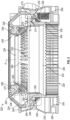
FIG. 2 is a side view of a bearing compartment with a support structure in accordance with embodiments; -
FIG. 3 is an enlarged view of a portion ofFIG. 2 including an upper portion of the support structure in accordance with embodiments; -
FIG. 4 is an enlarged view of a portion ofFIG. 2 including a lower portion of the support structure in accordance with embodiments; -
FIG. 5 is an enlarged view of a portion ofFIG. 2 including the upper portion of the support structure in accordance with embodiments; -
FIG. 6 is an enlarged view of a portion ofFIG. 2 including the lower portion of the support structure in accordance with embodiments; -
FIG. 7 is a flow diagram illustrating a method of manufacturing a support structure integrally formed with a bearing compartment in accordance with embodiments; and -
FIG. 8 is a flow diagram illustrating a method of processing a support structure integrally formed with a bearing compartment in accordance with embodiments. - These and other advantages and features will become more apparent from the following description taken in conjunction with the drawings.
- A detailed description of one or more embodiments of the disclosed apparatus and method are presented herein by way of exemplification and not limitation with reference to the Figures.
-
FIG. 1 schematically illustrates agas turbine engine 20. Thegas turbine engine 20 is disclosed herein as a two-spool turbofan that generally incorporates a fan section 22, acompressor section 24, acombustor section 26 and aturbine section 28. Alternative engines might include other systems or features. The fan section 22 drives air along a bypass flow path B in a bypass duct, while thecompressor section 24 drives air along a core flow path C for compression and communication into thecombustor section 26 and then expansion through theturbine section 28. Although depicted as a two-spool turbofan gas turbine engine in the disclosed non-limiting embodiment, it should be understood that the concepts described herein are not limited to use with two-spool turbofans as the teachings may be applied to other types of turbine engines including three-spool architectures. - The exemplary
gas turbine engine 20 generally includes alow speed spool 30 and ahigh speed spool 32 mounted for rotation about an engine central longitudinal axis A relative to an enginestatic structure 36 viaseveral bearing systems 38. It should be understood thatvarious bearing systems 38 at various locations may alternatively or additionally be provided, and the location ofbearing systems 38 may be varied as appropriate to the application. - The
low speed spool 30 generally includes aninner shaft 40 that interconnects afan 42, alow pressure compressor 44 and alow pressure turbine 46. Theinner shaft 40 is connected to thefan 42 through a speed change mechanism, which in exemplarygas turbine engine 20 is illustrated as a gearedarchitecture 48 to drive thefan 42 at a lower speed than thelow speed spool 30. Thehigh speed spool 32 includes anouter shaft 50 that interconnects ahigh pressure compressor 52 andhigh pressure turbine 54. Acombustor 56 is arranged in thegas turbine engine 20 between thehigh pressure compressor 52 and thehigh pressure turbine 54. The enginestatic structure 36 is arranged generally between thehigh pressure turbine 54 and thelow pressure turbine 46. The enginestatic structure 36 further supports thebearing systems 38 in theturbine section 28. Theinner shaft 40 and theouter shaft 50 are concentric and rotate viabearing systems 38 about the engine central longitudinal axis A which is collinear with their longitudinal axes. - The core airflow is compressed by the
low pressure compressor 44 and then thehigh pressure compressor 52, is mixed and burned with fuel in thecombustor 56 and is then expanded over thehigh pressure turbine 54 and thelow pressure turbine 46. The high andlow pressure turbines low speed spool 30 and thehigh speed spool 32, respectively, in response to the expansion. It will be appreciated that each of the positions of the fan section 22,compressor section 24,combustor section 26,turbine section 28, and fandrive gear system 48 may be varied. For example, gearedarchitecture 48 may be located aft of thecombustor section 26 or even aft of theturbine section 28, and the fan section 22 may be positioned forward or aft of the location of gearedarchitecture 48. - The
gas turbine engine 20 in one example is a high-bypass geared aircraft engine. In a further example, thegas turbine engine 20 bypass ratio is greater than about six (6), with an example embodiment being greater than about ten (10), the gearedarchitecture 48 is an epicyclic gear train, such as a planetary gear system or other gear system, with a gear reduction ratio of greater than about 2.3 and thelow pressure turbine 46 has a pressure ratio that is greater than about five. In one disclosed embodiment, thegas turbine engine 20 bypass ratio is greater than about ten (10:1), the fan diameter is significantly larger than that of thelow pressure compressor 44, and thelow pressure turbine 46 has a pressure ratio that is greater than about five 5:1.Low pressure turbine 46 pressure ratio is pressure measured prior to inlet oflow pressure turbine 46 as related to the pressure at the outlet of thelow pressure turbine 46 prior to an exhaust nozzle. The gearedarchitecture 48 may be an epicycle gear train, such as a planetary gear system or other gear system, with a gear reduction ratio of greater than about 2.3:1. It should be understood, however, that the above parameters are only exemplary of one embodiment of a geared architecture engine and that the present disclosure is applicable to other gas turbine engines including direct drive turbofans. - A significant amount of thrust is provided by the bypass flow B due to the high bypass ratio. The fan section 22 of the
gas turbine engine 20 is designed for a particular flight condition--typically cruise at about 0.8 Mach and about 35,000 feet (10,688 meters). The flight condition of 0.8 Mach and 35,000 ft (10,688 meters), with the engine at its best fuel consumption--also known as "bucket cruise Thrust Specific Fuel Consumption ('TSFC')"--is the industry standard parameter of lbm of fuel being burned divided by lbf of thrust the engine produces at that minimum point. "Low fan pressure ratio" is the pressure ratio across the fan blade alone, without a Fan Exit Guide Vane ("FEGV") system. The low fan pressure ratio as disclosed herein according to one non-limiting embodiment is less than about 1.45. "Low corrected fan tip speed" is the actual fan tip speed in ft/sec divided by an industry standard temperature correction of [(Tram °R)/(518.7 °R)]0.5. The "Low corrected fan tip speed" as disclosed herein according to one non-limiting embodiment is less than about 1150 ft/second (350.5 m/sec). - With continued reference to
FIG. 1 and with additional reference toFIGS. 2-6 , abearing compartment 202 of thegas turbine engine 20 ofFIG. 1 can be additively manufactured and include a number of features with a complex geometry. Thebearing compartment 202 can be part of the bearingsystems 38 to support rotation of one or more shafts, such as theinner shaft 40 or theouter shaft 50. In the example ofFIG. 2 , thebearing compartment 202 includes ahousing 230. Thehousing 230 can include alower housing portion 232 and anupper housing portion 234. Rather than separately manufacturing thelower housing portion 232 and theupper housing portion 234, thehousing 230 can be monolithically formed through an additive manufacturing process. - A
first overhang region 236 that is supported by asupport structure 220 during an additive manufacturing build process can be formed between thelower housing portion 232 and theupper housing portion 234. Asecond overhang region 238 of theupper housing portion 234 can be supported by thesupport structure 220 during the additive manufacturing build process. Thesupport structure 220 can include alower portion 222 in contact with thefirst overhang region 236 and anupper portion 224 that extends from thefirst overhang region 236 to thesecond overhang region 238 that is radially inward of thefirst overhang region 236. Asidewall support 225 connects thelower portion 222 to theupper portion 224 of thesupport structure 220. Thebearing compartment 202 can be manufactured using a powder bed fusion process, e.g., laser or electron beam based, to progressively build thehousing 230 from thelower housing portion 232 to theupper housing portion 234 while also building thesupport structure 220 within an interior of thehousing 230. Forming thesupport structure 220 integrally with thehousing 230 can enhance structural stability as vertical and horizontal support extends to multiple locations within thehousing 230. Rather than using generalized supports, thesupport structure 220 can incorporate features that provide additional aspects beyond supporting the initial build process. Thesupport structure 220 can include a plurality ofvertical supports 226 andhorizontal supports 228 with one or more features to support machining of thebearing compartment 202 and removal of thesupport structure 220 from thebearing compartment 202. Machining can include grinding, cutting, milling, polishing, and/or other such processes that remove material. - One example of the one or more features to support machining can include a hold-
down point 240. The hold-down point 240 can be, for example, a bolt hole or flat region for clamping. Thesupport structure 220 can also include multiple encapsulation region, such asencapsulation regions bearing compartment 202 to be exposed by machining as part of the removal of thesupport structure 220. For instance, surfaces of afirst interface 262 can be exposed upon machining of theencapsulation region 242, surfaces of asecond interface 264 can be exposed upon machining of theencapsulation region 244, surfaces of athird interface 266 can be exposed upon machining of theencapsulation region 246, surfaces of afourth interface 268 can be exposed upon machining of theencapsulation region 248, surfaces of afifth interface 270 can be exposed upon machining of theencapsulation region 250, and surfaces of asixth interface 272 can be exposed upon machining of theencapsulation region 252. The encapsulation regions 242-252 can wrap around surfaces, such as forinterfaces interfaces - As another example of the one or more features to support machining, at least one of the one or more features can include a
datum 274 to provide a reference for machining or tooling plate positioning. Thedatum 274 can be, for example, a portion of thesupport structure 220 having a change in internal characteristics, such as an internal lattice structure or gaps that become visible as material is removed. Further, thedatum 274 can be a surface variation where a flat surface is incorporated on a larger curved surface. Further, thedatum 274 can include a marking that is externally visible or becomes visible as material is removed from thesupport structure 220. Thedatum 274 can be part of a sequence of the one or more features incorporated within thesupport structure 220 such that at least one of the one or more features is revealed as thesupport structure 220 is removed from thebearing compartment 202. For instance, thedatum 274 can be revealed as theencapsulation region 242 is machined away, and anotherfeature 276 within theencapsulation region 244 can be revealed to assist in identifying wherecorner 278 should be formed. - The
lower portion 222 of thesupport structure 220 can include a plurality ofstruts 282 that extend axially within thehousing 230. Thestruts 282 can form a portion of the vertical supports 226. Thestruts 282 can extend axially in parallel to an axis of rotation (e.g., engine central longitudinal axis A) defined within a central cavity of thebearing compartment 202. Theupper portion 224 of thesupport structure 220 can include a plurality ofstruts 284 that provide an inner support for thevertical supports 226 andhorizontal supports 228 of theupper housing portion 234. - Other support structures can also be incorporated into the
housing 230. For example, anouter support structure 290 can be integrally formed at an outer diameter of thehousing 230. Theouter support structure 290 may also include one or more features to support machining of thebearing compartment 202. For example, theouter support structure 290 may provide a clamping location to hold thebearing compartment 202 during processing to avoid damaging the remaining surfaces of thehousing 230. -
FIGS. 3 and 5 are enlarged views of portions ofFIG. 2 including theupper portion 224 of thesupport structure 220 in accordance with embodiments.FIGS. 4 and 6 are enlarged views of portions ofFIG. 2 including thelower portion 222 of thesupport structure 220 in accordance with embodiments. Peak locations 285 betweenstruts 284 of theupper portion 224 can serve as features to identify specific locations. For instance, the spacing between the peak locations 285 may not be uniform. Areference strut 284A can be defined betweenpeak 285A and peak 285B. Thereference strut 284A may have a larger width than a width W1 of astrut 284 defined betweenpeaks peaks peaks struts 282 of thelower portion 222. Further, a thickness T1 (FIG. 2 ) ofsidewall support 225 can be less than a thickness T2 ofstrut 284 of theupper portion 224. Further, a thickness T3 ofstrut 282 of thelower portion 222 can be greater than thickness T2. Thethicknesses T 1, T2, T3 and other dimensions of thesupport structure 220 can be selected to handle thermal conditions that may exist during the initial build or subsequent machining processes. - With reference to
FIG. 7 , amethod 700 of manufacturing asupport structure 220 integrally formed with abearing compartment 202 is provided. Themethod 700 is described with reference toFIGS. 1-7 and can include additional steps beyond those depicted inFIG. 7 . Atblock 702, themethod 700 includes additively manufacturing alower portion 222 of thesupport structure 220 in contact with afirst overhang region 236 of ahousing 230 of thebearing compartment 202. Atblock 704, themethod 700 includes additively manufacturing anupper portion 224 of thesupport structure 220 that extends from thefirst overhang region 236 to asecond overhang region 238 of thehousing 230 that is radially inward of thefirst overhang region 236. Thesupport structure 220 can include a plurality ofvertical supports 226 andhorizontal supports 228 with one or more features to support machining of thebearing compartment 202 and removal of thesupport structure 220 from thebearing compartment 202. - In some embodiments, the one or more features to support machining include a hold-
down point 240. The hold-down point 240 can be a bolt hole or flat region for clamping, for example. Themethod 700 can also include forming an encapsulation region that covers at least two surfaces of thebearing compartment 202 to be exposed by machining as part of the removal of thesupport structure 220, such as encapsulation regions 242-252. Themethod 700 can also include incorporating adatum 274 into thesupport structure 220 as at least one of the one or more features to provide a reference for machining or tooling plate positioning. Themethod 700 can also include incorporating within the support structure 220 a sequence of the one or more features such that at least one of the one or more features is revealed as thesupport structure 220 is removed from thebearing compartment 202, such asfeature 276 that may be revealed afterdatum 274 during the material removal process. - With reference to
FIG. 8 , amethod 800 of processing asupport structure 220 integrally formed with abearing compartment 202 is provided. Themethod 800 is described with reference toFIGS. 1-8 and can include additional steps beyond those depicted inFIG. 8 . Themethod 800 can be performed in conjunction with themethod 700 ofFIG. 7 . Atblock 802, themethod 800 includes positioning thesupport structure 220 for machining of thebearing compartment 202 using one or more features of thesupport structure 220. Thesupport structure 220 can include alower portion 222 in contact with afirst overhang region 236 of ahousing 230 of thebearing compartment 202 and anupper portion 224 that extends from thefirst overhang region 236 to asecond overhang region 238 of thehousing 230 that is radially inward of thefirst overhang region 236. Atblock 804, thelower portion 222 of thesupport structure 220 is removed. Atblock 806, theupper portion 224 of thesupport structure 220 is removed. Themethod 800 can include machining an encapsulation region to expose at least two surfaces of thebearing compartment 202 covered by thesupport structure 220, such as encapsulation regions 242-252. - Benefits of the features described herein include a support structure integrally formed with a bearing compartment through the use of additive manufacturing that allows for complex geometries. Features incorporated into the support structure can provide positioning reference points, hold-downs, and define processing sequences to reduce the post-processing burdens and risk of component damage during the machining process.
- The term "about" is intended to include the degree of error associated with measurement of the particular quantity based upon the equipment available at the time of filing the application. Terms such as "upper" and "lower" are used for purposes of explanation and the designation as such can be altered depending upon component orientation.
- The terminology used herein is for the purpose of describing particular embodiments only and is not intended to be limiting of the present disclosure. As used herein, the singular forms "a", "an" and "the" are intended to include the plural forms as well, unless the context clearly indicates otherwise. It will be further understood that the terms "comprises" and/or "comprising," when used in this specification, specify the presence of stated features, integers, steps, operations, elements, and/or components, but do not preclude the presence or addition of one or more other features, integers, steps, operations, element components, and/or groups thereof.
- While the present disclosure has been described with reference to an exemplary embodiment or embodiments, it will be understood by those skilled in the art that various changes may be made and equivalents may be substituted for elements thereof without departing from the scope of the present disclosure. In addition, many modifications may be made to adapt a particular situation or material to the teachings of the present disclosure without departing from the essential scope thereof. Therefore, it is intended that the present disclosure not be limited to the particular embodiment disclosed as the best mode contemplated for carrying out this present disclosure, but that the present disclosure will include all embodiments falling within the scope of the claims.
Claims (15)
- A support structure (220) integrally formed with a bearing compartment (202), the support structure (220) comprising:
a plurality of vertical supports (226) and horizontal supports (228) comprising one or more features (274, 276) to support machining of the bearing compartment (202) and removal of the support structure (220) from the bearing compartment (202). - The support structure of claim 1, further comprising an encapsulation region (242, 244, 246, 248, 250, 252) that covers at least two surfaces of the bearing compartment (202) to be exposed by machining as part of the removal of the support structure (220).
- The support structure of claim 1 or 2, wherein at least one of the one or more features (274, 276) comprises a datum (274) to provide a reference for machining or tooling plate positioning.
- The support structure of claim 3, wherein a sequence of the one or more features (274, 276) is incorporated within the support structure (220) such that at least one of the one or more features (274, 276) is revealed as the support structure (220) is removed from the bearing compartment (202).
- The support structure of any preceding claim, further comprising:a lower portion (222) that contacts with a first overhang region (236) of a housing (230) of the bearing compartment (202); andan upper portion (224) that extends from the first overhang region (236) to a second overhang region (238) of the housing (230) that is radially inward of the first overhang region (236).
- A method of manufacturing a support structure (220) integrally formed with a bearing compartment (202), the method comprising:additively manufacturing a lower portion (222) of the support structure (220) in contact with a first overhang region (236) of a housing (230) of the bearing compartment (202); andadditively manufacturing an upper portion (224) of the support structure (220) that extends from the first overhang region (236) to a second overhang region (238) of the housing (230) that is radially inward of the first overhang region (236), wherein the support structure (220) comprises a plurality of vertical supports (226) and horizontal supports (228) with one or more features (274, 276) to support machining of the bearing compartment (202) and removal of the support structure (220) from the bearing compartment (202).
- The method of claim 6, further comprising:
forming an encapsulation region (242, 244, 246, 248, 250, 252) that covers at least two surfaces of the bearing compartment (202) to be exposed by machining as part of the removal of the support structure (220). - The method of claim 6 or 7, further comprising:
incorporating a datum (274) into the support structure (220) as at least one of the one or more features (274, 276) to provide a reference for machining or tooling plate positioning. - The method of any of claims 6 to 8, further comprising:
incorporating within the support structure (220) a sequence of the one or more features (274, 276) such that at least one of the one or more features (274, 276) is revealed as the support structure (220) is removed from the bearing compartment (202). - A method of processing a support structure (220) integrally formed with a bearing compartment (202), the method comprising:positioning the support structure (220) for machining of the bearing compartment (202) using one or more features (274, 276) of the support structure (220), wherein the support structure (220) comprises a lower portion (222) in contact with a first overhang region (236) of a housing (230) of the bearing compartment (202) and an upper portion (224) that extends from the first overhang region (236) to a second overhang region (238) of the housing (230) that is radially inward of the first overhang region (236);removing the lower portion (222) of the support structure (220); andremoving the upper portion (224) of the support structure (220).
- The method of claim 10, wherein the support structure (220) comprises a plurality of vertical supports (226) and horizontal supports (228) comprising the one or more features (274, 276) to support machining of the bearing compartment (202) and removal of the support structure (220) from the bearing compartment (202).
- The method of claim 10 or 11, further comprising:
machining an encapsulation region (242, 244, 245, 248 250, 252) to expose at least two surfaces of the bearing compartment (202) covered by the support structure (220). - The method of any of claims 10 to 12, wherein at least one of the one or more features (274, 276) comprises a datum (274) to provide a reference for machining or tooling plate positioning, wherein a sequence of the one or more features (274, 276) is optionally incorporated within the support structure (220) such that at least one of the one or more features (274, 276) is revealed as the support structure (220) is removed from the bearing compartment (202).
- The support structure or method of any preceding claim, wherein the one or more features (274, 276) to support machining comprise a hold-down point (240).
- The support structure or method of claim 14, wherein the hold-down point (240) is a bolt hole or flat region for clamping.
Applications Claiming Priority (1)
| Application Number | Priority Date | Filing Date | Title |
|---|---|---|---|
| US202263423279P | 2022-11-07 | 2022-11-07 |
Publications (2)
| Publication Number | Publication Date |
|---|---|
| EP4365411A2 true EP4365411A2 (en) | 2024-05-08 |
| EP4365411A3 EP4365411A3 (en) | 2024-08-14 |
Family
ID=88697766
Family Applications (1)
| Application Number | Title | Priority Date | Filing Date |
|---|---|---|---|
| EP23207928.5A Pending EP4365411A3 (en) | 2022-11-07 | 2023-11-06 | Support structure for bearing compartment |
Country Status (2)
| Country | Link |
|---|---|
| US (2) | US12313001B2 (en) |
| EP (1) | EP4365411A3 (en) |
Families Citing this family (1)
| Publication number | Priority date | Publication date | Assignee | Title |
|---|---|---|---|---|
| US12313001B2 (en) * | 2022-11-07 | 2025-05-27 | Rtx Corporation | Support structure for bearing compartment |
Family Cites Families (22)
| Publication number | Priority date | Publication date | Assignee | Title |
|---|---|---|---|---|
| US10001028B2 (en) * | 2012-04-23 | 2018-06-19 | General Electric Company | Dual spring bearing support housing |
| US9539764B2 (en) | 2013-03-15 | 2017-01-10 | United Technologies Corporation | Usage of a witness mark to distinguish support structure from part |
| US10138757B2 (en) * | 2013-08-20 | 2018-11-27 | United Technologies Corporation | Bearing system for gas turbine engine |
| US9933017B2 (en) * | 2013-12-20 | 2018-04-03 | United Technologies Corporation | Bearing supports |
| US20160146052A1 (en) * | 2014-11-25 | 2016-05-26 | United Technologies Corporation | Forged cast forged outer case for a gas turbine engine |
| FR3046556B1 (en) | 2016-01-07 | 2023-11-03 | Snecma | METHOD FOR MANUFACTURING PARTS BY ADDITIVE MANUFACTURING |
| DE102017101835A1 (en) | 2017-01-31 | 2018-08-02 | Amsis Gmbh | Process for the powder bed-based additive production of at least one component and powder bed additive manufactured component (s) as well as plant and construction platform for carrying out the process |
| US10563580B2 (en) * | 2017-05-16 | 2020-02-18 | Rolls-Royce Corporation | Engine sump with air separation features |
| BE1025975B1 (en) * | 2018-02-02 | 2019-09-03 | Safran Aero Boosters S.A. | STRUCTURAL CASING FOR AXIAL TURBOMACHINE |
| DE102018202083A1 (en) | 2018-02-09 | 2019-08-14 | MTU Aero Engines AG | STORAGE CHAMBER HOUSING FOR A FLOW MACHINE |
| FR3079152B1 (en) | 2018-03-23 | 2020-11-06 | Safran Aircraft Engines | OPTIMIZATION OF SUBSTRATES FOR THE ADDITIVE MANUFACTURING OF A PART |
| FR3079153B1 (en) | 2018-03-23 | 2020-04-24 | Safran Aircraft Engines | BEARING SUPPORT FOR AN AIRCRAFT ENGINE MANUFACTURED BY ADDITIVE MANUFACTURING |
| FR3079151B1 (en) | 2018-03-23 | 2020-10-30 | Safran Aircraft Engines | OPTIMIZATION OF SUPPORTS FOR ADDITIVE PART MANUFACTURING WITH A RECESS |
| US20190309629A1 (en) | 2018-04-05 | 2019-10-10 | United Technologies Corporation | Turbine blades and vanes for gas turbine engine |
| EP3814230B1 (en) | 2018-06-28 | 2022-10-12 | BAE SYSTEMS plc | Method and system for attaching an aircraft skin to an aircraft airframe |
| DE102019121908A1 (en) | 2018-08-14 | 2020-02-20 | Laboratoires Bodycad Inc. | 3D printing arrangement and process |
| US10941944B2 (en) * | 2018-10-04 | 2021-03-09 | Raytheon Technologies Corporation | Consumable support structures for additively manufactured combustor components |
| US11738519B2 (en) | 2019-05-03 | 2023-08-29 | Raytheon Technologies Corporation | Systems and methods for support material removal |
| EP3791976A1 (en) | 2019-09-10 | 2021-03-17 | Siemens Aktiengesellschaft | Support structure |
| FR3118891B1 (en) | 2021-01-15 | 2023-03-24 | Safran Aircraft Engines | Manufacture of a turbine injector by laser fusion on a powder bed |
| FR3127521B1 (en) | 2021-09-24 | 2023-12-15 | Safran Aircraft Engines | COOLING AIR INJECTION HOUSING FOR TURBOMACHINE TURBINE |
| US12313001B2 (en) | 2022-11-07 | 2025-05-27 | Rtx Corporation | Support structure for bearing compartment |
-
2023
- 2023-10-27 US US18/496,079 patent/US12313001B2/en active Active
- 2023-11-06 EP EP23207928.5A patent/EP4365411A3/en active Pending
-
2025
- 2025-05-23 US US19/217,713 patent/US12601295B2/en active Active
Also Published As
| Publication number | Publication date |
|---|---|
| US12601295B2 (en) | 2026-04-14 |
| US20250347248A1 (en) | 2025-11-13 |
| US20240151181A1 (en) | 2024-05-09 |
| EP4365411A3 (en) | 2024-08-14 |
| US12313001B2 (en) | 2025-05-27 |
Similar Documents
| Publication | Publication Date | Title |
|---|---|---|
| EP3734018A1 (en) | Seal for a gas turbine engine | |
| US9796055B2 (en) | Turbine case retention hook with insert | |
| EP3415257A1 (en) | Systems and methods for manufacturing film cooling hole diffuser portion and film cooling hole | |
| US20210254504A1 (en) | Method of creating heat transfer features in high temperature alloys | |
| US12601295B2 (en) | Support structure for bearing compartment | |
| US20160047259A1 (en) | Gas turbine engine stress isolation scallop | |
| EP3103965B1 (en) | Attachment arrangement for turbine engine blade outer air seal | |
| EP3771514A1 (en) | Baffle tube with two datum features | |
| WO2014109801A2 (en) | Gas turbine engine cooling hole with circular exit geometry | |
| EP2993303B1 (en) | Gas turbine engine component with film cooling hole with pocket | |
| EP2961961B1 (en) | Method of fabricating an airfoil cluster and corresponding airfoil cluster | |
| EP3170983B1 (en) | Platform and corresponding method of manufacturing | |
| US11828193B2 (en) | Vane core assemblies and methods | |
| US11098604B2 (en) | Radial-axial cooling slots | |
| US12460559B2 (en) | Support structure and spring for bearing compartment | |
| CA3101621C (en) | System and method for performing operations on an engine | |
| EP3696380A1 (en) | Adapter for positioning a machining tool between two aerofoils | |
| US12421872B2 (en) | Spring damping for bearing compartment | |
| US11028719B2 (en) | Brush seal repair method | |
| EP3550105B1 (en) | Gas turbine engine rotor disk |
Legal Events
| Date | Code | Title | Description |
|---|---|---|---|
| PUAI | Public reference made under article 153(3) epc to a published international application that has entered the european phase |
Free format text: ORIGINAL CODE: 0009012 |
|
| STAA | Information on the status of an ep patent application or granted ep patent |
Free format text: STATUS: THE APPLICATION HAS BEEN PUBLISHED |
|
| AK | Designated contracting states |
Kind code of ref document: A2 Designated state(s): AL AT BE BG CH CY CZ DE DK EE ES FI FR GB GR HR HU IE IS IT LI LT LU LV MC ME MK MT NL NO PL PT RO RS SE SI SK SM TR |
|
| PUAL | Search report despatched |
Free format text: ORIGINAL CODE: 0009013 |
|
| AK | Designated contracting states |
Kind code of ref document: A3 Designated state(s): AL AT BE BG CH CY CZ DE DK EE ES FI FR GB GR HR HU IE IS IT LI LT LU LV MC ME MK MT NL NO PL PT RO RS SE SI SK SM TR |
|
| RIC1 | Information provided on ipc code assigned before grant |
Ipc: F01D 25/28 20060101ALI20240711BHEP Ipc: B22F 10/47 20210101ALI20240711BHEP Ipc: B22F 10/28 20210101ALI20240711BHEP Ipc: F01D 25/16 20060101AFI20240711BHEP |
|
| STAA | Information on the status of an ep patent application or granted ep patent |
Free format text: STATUS: REQUEST FOR EXAMINATION WAS MADE |
|
| 17P | Request for examination filed |
Effective date: 20250213 |