EP4365140A1 - Water filtration system - Google Patents
Water filtration system Download PDFInfo
- Publication number
- EP4365140A1 EP4365140A1 EP22832988.4A EP22832988A EP4365140A1 EP 4365140 A1 EP4365140 A1 EP 4365140A1 EP 22832988 A EP22832988 A EP 22832988A EP 4365140 A1 EP4365140 A1 EP 4365140A1
- Authority
- EP
- European Patent Office
- Prior art keywords
- power
- water filtration
- water
- filtration system
- generator
- Prior art date
- Legal status (The legal status is an assumption and is not a legal conclusion. Google has not performed a legal analysis and makes no representation as to the accuracy of the status listed.)
- Granted
Links
Images



Classifications
-
- C—CHEMISTRY; METALLURGY
- C02—TREATMENT OF WATER, WASTE WATER, SEWAGE, OR SLUDGE
- C02F—TREATMENT OF WATER, WASTE WATER, SEWAGE, OR SLUDGE
- C02F1/00—Treatment of water, waste water, or sewage
- C02F1/44—Treatment of water, waste water, or sewage by dialysis, osmosis or reverse osmosis
- C02F1/441—Treatment of water, waste water, or sewage by dialysis, osmosis or reverse osmosis by reverse osmosis
-
- B—PERFORMING OPERATIONS; TRANSPORTING
- B01—PHYSICAL OR CHEMICAL PROCESSES OR APPARATUS IN GENERAL
- B01D—SEPARATION
- B01D61/00—Processes of separation using semi-permeable membranes, e.g. dialysis, osmosis or ultrafiltration; Apparatus, accessories or auxiliary operations specially adapted therefor
- B01D61/02—Reverse osmosis; Hyperfiltration ; Nanofiltration
- B01D61/025—Reverse osmosis; Hyperfiltration
- B01D61/026—Reverse osmosis; Hyperfiltration comprising multiple reverse osmosis steps
-
- B—PERFORMING OPERATIONS; TRANSPORTING
- B01—PHYSICAL OR CHEMICAL PROCESSES OR APPARATUS IN GENERAL
- B01D—SEPARATION
- B01D61/00—Processes of separation using semi-permeable membranes, e.g. dialysis, osmosis or ultrafiltration; Apparatus, accessories or auxiliary operations specially adapted therefor
- B01D61/02—Reverse osmosis; Hyperfiltration ; Nanofiltration
- B01D61/04—Feed pretreatment
-
- B—PERFORMING OPERATIONS; TRANSPORTING
- B01—PHYSICAL OR CHEMICAL PROCESSES OR APPARATUS IN GENERAL
- B01D—SEPARATION
- B01D61/00—Processes of separation using semi-permeable membranes, e.g. dialysis, osmosis or ultrafiltration; Apparatus, accessories or auxiliary operations specially adapted therefor
- B01D61/02—Reverse osmosis; Hyperfiltration ; Nanofiltration
- B01D61/10—Accessories; Auxiliary operations
-
- B—PERFORMING OPERATIONS; TRANSPORTING
- B01—PHYSICAL OR CHEMICAL PROCESSES OR APPARATUS IN GENERAL
- B01D—SEPARATION
- B01D61/00—Processes of separation using semi-permeable membranes, e.g. dialysis, osmosis or ultrafiltration; Apparatus, accessories or auxiliary operations specially adapted therefor
- B01D61/02—Reverse osmosis; Hyperfiltration ; Nanofiltration
- B01D61/12—Controlling or regulating
-
- B—PERFORMING OPERATIONS; TRANSPORTING
- B01—PHYSICAL OR CHEMICAL PROCESSES OR APPARATUS IN GENERAL
- B01D—SEPARATION
- B01D65/00—Accessories or auxiliary operations, in general, for separation processes or apparatus using semi-permeable membranes
-
- B—PERFORMING OPERATIONS; TRANSPORTING
- B01—PHYSICAL OR CHEMICAL PROCESSES OR APPARATUS IN GENERAL
- B01D—SEPARATION
- B01D67/00—Processes specially adapted for manufacturing semi-permeable membranes for separation processes or apparatus
- B01D67/0081—After-treatment of organic or inorganic membranes
- B01D67/0097—Storing or preservation
-
- C—CHEMISTRY; METALLURGY
- C02—TREATMENT OF WATER, WASTE WATER, SEWAGE, OR SLUDGE
- C02F—TREATMENT OF WATER, WASTE WATER, SEWAGE, OR SLUDGE
- C02F1/00—Treatment of water, waste water, or sewage
- C02F1/001—Processes for the treatment of water whereby the filtration technique is of importance
-
- B—PERFORMING OPERATIONS; TRANSPORTING
- B01—PHYSICAL OR CHEMICAL PROCESSES OR APPARATUS IN GENERAL
- B01D—SEPARATION
- B01D2311/00—Details relating to membrane separation process operations and control
- B01D2311/04—Specific process operations in the feed stream; Feed pretreatment
-
- B—PERFORMING OPERATIONS; TRANSPORTING
- B01—PHYSICAL OR CHEMICAL PROCESSES OR APPARATUS IN GENERAL
- B01D—SEPARATION
- B01D2311/00—Details relating to membrane separation process operations and control
- B01D2311/24—Quality control
- B01D2311/243—Electrical conductivity control
-
- B—PERFORMING OPERATIONS; TRANSPORTING
- B01—PHYSICAL OR CHEMICAL PROCESSES OR APPARATUS IN GENERAL
- B01D—SEPARATION
- B01D2311/00—Details relating to membrane separation process operations and control
- B01D2311/26—Further operations combined with membrane separation processes
- B01D2311/2649—Filtration
-
- B—PERFORMING OPERATIONS; TRANSPORTING
- B01—PHYSICAL OR CHEMICAL PROCESSES OR APPARATUS IN GENERAL
- B01D—SEPARATION
- B01D2313/00—Details relating to membrane modules or apparatus
- B01D2313/06—External membrane module supporting or fixing means
-
- B—PERFORMING OPERATIONS; TRANSPORTING
- B01—PHYSICAL OR CHEMICAL PROCESSES OR APPARATUS IN GENERAL
- B01D—SEPARATION
- B01D2313/00—Details relating to membrane modules or apparatus
- B01D2313/18—Specific valves
-
- B—PERFORMING OPERATIONS; TRANSPORTING
- B01—PHYSICAL OR CHEMICAL PROCESSES OR APPARATUS IN GENERAL
- B01D—SEPARATION
- B01D2313/00—Details relating to membrane modules or apparatus
- B01D2313/36—Energy sources
- B01D2313/367—Renewable energy sources, e.g. wind or solar sources
-
- B—PERFORMING OPERATIONS; TRANSPORTING
- B01—PHYSICAL OR CHEMICAL PROCESSES OR APPARATUS IN GENERAL
- B01D—SEPARATION
- B01D2313/00—Details relating to membrane modules or apparatus
- B01D2313/50—Specific extra tanks
- B01D2313/501—Permeate storage tanks
-
- B—PERFORMING OPERATIONS; TRANSPORTING
- B01—PHYSICAL OR CHEMICAL PROCESSES OR APPARATUS IN GENERAL
- B01D—SEPARATION
- B01D2313/00—Details relating to membrane modules or apparatus
- B01D2313/70—Control means using a programmable logic controller [PLC] or a computer
-
- B—PERFORMING OPERATIONS; TRANSPORTING
- B01—PHYSICAL OR CHEMICAL PROCESSES OR APPARATUS IN GENERAL
- B01D—SEPARATION
- B01D2317/00—Membrane module arrangements within a plant or an apparatus
- B01D2317/02—Elements in series
- B01D2317/025—Permeate series
-
- B—PERFORMING OPERATIONS; TRANSPORTING
- B01—PHYSICAL OR CHEMICAL PROCESSES OR APPARATUS IN GENERAL
- B01D—SEPARATION
- B01D2317/00—Membrane module arrangements within a plant or an apparatus
- B01D2317/06—Use of membrane modules of the same kind
-
- C—CHEMISTRY; METALLURGY
- C02—TREATMENT OF WATER, WASTE WATER, SEWAGE, OR SLUDGE
- C02F—TREATMENT OF WATER, WASTE WATER, SEWAGE, OR SLUDGE
- C02F1/00—Treatment of water, waste water, or sewage
- C02F1/006—Water distributors either inside a treatment tank or directing the water to several treatment tanks; Water treatment plants incorporating these distributors, with or without chemical or biological tanks
-
- C—CHEMISTRY; METALLURGY
- C02—TREATMENT OF WATER, WASTE WATER, SEWAGE, OR SLUDGE
- C02F—TREATMENT OF WATER, WASTE WATER, SEWAGE, OR SLUDGE
- C02F2103/00—Nature of the water, waste water, sewage or sludge to be treated
- C02F2103/007—Contaminated open waterways, rivers, lakes or ponds
-
- C—CHEMISTRY; METALLURGY
- C02—TREATMENT OF WATER, WASTE WATER, SEWAGE, OR SLUDGE
- C02F—TREATMENT OF WATER, WASTE WATER, SEWAGE, OR SLUDGE
- C02F2103/00—Nature of the water, waste water, sewage or sludge to be treated
- C02F2103/08—Seawater, e.g. for desalination
-
- C—CHEMISTRY; METALLURGY
- C02—TREATMENT OF WATER, WASTE WATER, SEWAGE, OR SLUDGE
- C02F—TREATMENT OF WATER, WASTE WATER, SEWAGE, OR SLUDGE
- C02F2201/00—Apparatus for treatment of water, waste water or sewage
- C02F2201/008—Mobile apparatus and plants, e.g. mounted on a vehicle
-
- C—CHEMISTRY; METALLURGY
- C02—TREATMENT OF WATER, WASTE WATER, SEWAGE, OR SLUDGE
- C02F—TREATMENT OF WATER, WASTE WATER, SEWAGE, OR SLUDGE
- C02F2201/00—Apparatus for treatment of water, waste water or sewage
- C02F2201/009—Apparatus with independent power supply, e.g. solar cells, windpower or fuel cells
-
- C—CHEMISTRY; METALLURGY
- C02—TREATMENT OF WATER, WASTE WATER, SEWAGE, OR SLUDGE
- C02F—TREATMENT OF WATER, WASTE WATER, SEWAGE, OR SLUDGE
- C02F2209/00—Controlling or monitoring parameters in water treatment
- C02F2209/001—Upstream control, i.e. monitoring for predictive control
-
- C—CHEMISTRY; METALLURGY
- C02—TREATMENT OF WATER, WASTE WATER, SEWAGE, OR SLUDGE
- C02F—TREATMENT OF WATER, WASTE WATER, SEWAGE, OR SLUDGE
- C02F2209/00—Controlling or monitoring parameters in water treatment
- C02F2209/005—Processes using a programmable logic controller [PLC]
-
- C—CHEMISTRY; METALLURGY
- C02—TREATMENT OF WATER, WASTE WATER, SEWAGE, OR SLUDGE
- C02F—TREATMENT OF WATER, WASTE WATER, SEWAGE, OR SLUDGE
- C02F2209/00—Controlling or monitoring parameters in water treatment
- C02F2209/05—Conductivity or salinity
-
- C—CHEMISTRY; METALLURGY
- C02—TREATMENT OF WATER, WASTE WATER, SEWAGE, OR SLUDGE
- C02F—TREATMENT OF WATER, WASTE WATER, SEWAGE, OR SLUDGE
- C02F2209/00—Controlling or monitoring parameters in water treatment
- C02F2209/42—Liquid level
-
- C—CHEMISTRY; METALLURGY
- C02—TREATMENT OF WATER, WASTE WATER, SEWAGE, OR SLUDGE
- C02F—TREATMENT OF WATER, WASTE WATER, SEWAGE, OR SLUDGE
- C02F2301/00—General aspects of water treatment
- C02F2301/04—Flow arrangements
- C02F2301/043—Treatment of partial or bypass streams
-
- C—CHEMISTRY; METALLURGY
- C02—TREATMENT OF WATER, WASTE WATER, SEWAGE, OR SLUDGE
- C02F—TREATMENT OF WATER, WASTE WATER, SEWAGE, OR SLUDGE
- C02F2301/00—General aspects of water treatment
- C02F2301/08—Multistage treatments, e.g. repetition of the same process step under different conditions
-
- C—CHEMISTRY; METALLURGY
- C02—TREATMENT OF WATER, WASTE WATER, SEWAGE, OR SLUDGE
- C02F—TREATMENT OF WATER, WASTE WATER, SEWAGE, OR SLUDGE
- C02F2303/00—Specific treatment goals
- C02F2303/24—Separation of coarse particles, e.g. by using sieves or screens
Definitions
- the present invention relates to a water filtration system that uses natural energy.
- Water filtration devices have been put to practical use for filtering seawater or freshwater from rivers or the like for drinking water and/or daily use.
- conventional water filtration devices are difficult to use in locations where there is no access to a grid power system.
- Patent Documents 1, 2 a technology that uses electric power generated by a solar panel or a wind turbine generator as the power to operate a pump and the like of a water filtration device has been proposed previously (Patent Documents 1, 2).
- Such a device places burdens of, for instance, separately transporting major mechanisms thereof and substantive assembling on an installation site. This may incur an increased cost for installation of the water filtration device.
- An object of the present invention is to provide a water filtration system which has a wider range of possibilities for its installation locations and which has an excellent transportability and can, therefore, lead to a reduced installation cost.
- the present invention provides a water filtration system including:
- the load in this context refers to electrically operated devices, including a pump configured to pump untreated water into a route.
- Such a configuration permits use of at least one power generator selected from a wind turbine generator, a photovoltaic generator, and a hydroelectric generator to provide power to a load of the water filtration device, thereby making it possible to operate the water filtration system even at locations where there is no access to a grid power system.
- the possibilities for installation locations of the water filtration system can be increased.
- the water filtration system also includes a structure which carries the water filtration device, the power generator and the power supply mechanism, the structure being transportable.
- the water filtration system can be transported and installed in an integrated fashion after being at least mostly assembled in a factory or the like. For this reason, it is possible to install the water filtration system more conveniently than a conventional construction which involves substantial assembling work on an installation site. As such, a water filtration system which has an excellent transportability and can, therefore, lead to a reduced installation cost can be realized.
- the water filtration system may further include a solar panel which is separate from the photovoltaic generator and configured to produce power supply for the load, the solar panel being configured to be releasably connected to an electrical connection unit provided to the structure.
- a solar panel which is separate from the photovoltaic generator and configured to produce power supply for the load
- the solar panel being configured to be releasably connected to an electrical connection unit provided to the structure.
- the solar panel is releasably connected to an electrical connection unit provided to the structure, so that convenient transfer of the water filtration system can be facilitated.
- the power supply mechanism may include a grid power system connection unit configured to receive power supplied from a grid power system.
- a grid power system connection unit configured to receive power supplied from a grid power system.
- the power supply mechanism may include a control device configured to apply a control to supply power generated by the power generator to the load.
- the control implemented by the control device in this context involves directing power generated by the power generator into a battery, etc. and drawing the directed power to the load.
- the water filtration device may include a tank configured to store filtered water
- the control device may include a tank water level determiner module configured to determine a level of water in the tank, and be configured to control the load to operate when the level of water determined by the tank water level determiner module is equal to or lower than a predetermined value.
- the predetermined value in this context is defined as appropriate during, for example, a design phase. For instance, an appropriate value is determined and defined through at least one of experiments or simulations.
- the control device can cause the load to operate when the tank has an unfilled volume which can be filled, so that filtered water can be reliably stored in the tank.
- the water filtration device, the power generator and the power supply mechanism can be operated efficiently.
- the power supply mechanism may include a battery configured to store power generated by the power generator and to direct the stored power to the load
- the control device may include a charge level determiner module configured to determine a charge level of the battery and be configured to control the load to operate when the charge level determined by the charge level determiner module is equal to or higher than a threshold value.
- the threshold value in this context is defined as appropriate during, for example, a design phase. For instance, an appropriate value is determined and defined through at least one of experiments or simulations.
- the control device causes the load to operate when the determined charge level is equal to or higher than a threshold value, making it possible to actively carry out water filtration using extra power that might previously have been missed.
- the water filtration device may include a route switching module configured to switch routes through which water is treated, and the control device includes an electrical conductivity determiner module configured to determine an electrical conductivity of the untreated water and be configured to control the route switching module to switch the routes in accordance with the electrical conductivity determined by the electrical conductivity determiner module.
- the electrical conductivity in this context indicates an ability of untreated water to conduct an electrical current and is the inverse of electrical resistivity.
- the relationship between electrical conductivity of untreated water and routes is predefined through experiments or simulations or the like. Such a configuration permits switching between routes for water treatment in accordance with the determined electrical conductivity, so that generated power can be effectively used.
- the structure may comprise a shipping container.
- the structure can be transferred using a variety of transport means such as truck, railroad, ship, and airplane.
- transport means such as truck, railroad, ship, and airplane.
- the shipping container can protect devices and others stored therein against possible malfunctions that may be caused by vibrations and impacts during transportation.
- a water filtration system 1 includes: a water filtration device 2 ( Fig. 2 ); natural energy power generators including both of a wind turbine generator 7 and a photovoltaic generator 8; a power supply mechanism 3 of Fig. 2 ; and a structure 4 which carries the water filtration device 2, the power generators 7, 8 of Fig. 1 , and the power supply mechanism 3 ( Fig. 2 ).
- the water filtration device 2 as shown in Fig. 2 is a device that filters seawater or freshwater from rivers or the like for drinking water and/or daily use.
- the power supply mechanism 3 supplies electric power from the power generators 7, 8 as shown in Fig. 1 to the load of the water filtration device 2 as shown in Fig. 2 in order to filter untreated water through the water filtration device 2.
- the structure 4 houses the water filtration device 2 as well as a control device 10 and a battery 11 of the power supply mechanism 3.
- the structure 4 is transportable and is a robust, box-shaped structure including, for example, double doors through which the water filtration device 2 and the power supply mechanism 3 can be carried in and out.
- the structure 4 includes a top wall 4a and a bottom wall 4b that are substantially rectangular in shape, and four peripheral walls 4c between the top wall 4a and the bottom wall 4b, thereby forming a generally cuboidal shape as a whole.
- the structure 4 comprises a shipping container.
- the "shipping container” used herein is preferably a container having a size that complies with a standard for freight transport containers - such as, for example, a domestic standard for freight containers of a country in which the container is transported.
- a standard for freight transport containers such as, for example, a domestic standard for freight containers of a country in which the container is transported.
- the "standard” in this context may be a standard established by a relevant domestic administrative agency in that country or an international organization such as the International Organization for Standardization (ISO), or may even be a JR container which serves as a de-facto standard for railroad freight transport containers in Japan.
- ISO International Organization for Standardization
- the structure 4 Being configured as a shipping container, the structure 4 can be transferred using a variety of transport means such as truck, railroad, ship, and airplane. With an excellent robustness, the shipping container can also protect devices and others stored therein against possible malfunctions that may be caused by vibrations and impacts during transportation.
- the wind turbine generator 7 includes a wind turbine 14 and a generator 15 that can be driven by the wind turbine 14 to generate power.
- the wind turbine 14 is configured as a vertical axis wind turbine.
- the wind turbine 14 includes a plurality of blades 14a (e.g., two blades 14a in the instant example) and a blade support 14b providing support for the blades 14a.
- Each of the blades 14a extends in the vertical direction, whereas the blade support 14b is supported on an upper end of a tower 16 so as to be rotatable about the vertical axis by means of a bearing arrangement (not shown).
- the two blades 14a are positioned angularly apart from each other by 180 degrees about the axis of the tower 16. Further, the tower 16 is secured centrally to an upper part of one of the peripheral walls 4c of the structure 4.
- the generator 15 of the wind turbine generator 7 is disposed inside a generator casing 17 that is attached to the top of the tower 16. Stationary race(s) of the bearing arrangement is/are fitted to the generator casing 17, whereas rotary race(s) of the bearing arrangement is/are coupled to the blade support 14b.
- the generator 15 generates power as a rotor of the generator 15 rotates inside the generator casing 17 along with the rotary race(s) in response to the revolutions of the wind turbine 14.
- an induction generator or a synchronous generator can be used for the generator 15.
- a vertical axis wind turbine is suited as the wind turbine 14 for use with the wind turbine generator 7 that is provided to the transportable structure 4 in that a vertical axis wind turbine can be configured in a relatively small size but still can receive wind to generate power. Nevertheless, the wind turbine may alternatively be a horizontal axis wind turbine.
- the photovoltaic generator 8 includes a solar panel 8a that receives sunlight for photoelectric conversion and a panel mount 8b that attaches the solar panel 8a to the structure 4.
- the solar panel 8a is attached onto the top wall 4a of the structure 4 by means of the panel mount 8b.
- the solar panel 8a may alternatively be disposed on a given one of the peripheral walls 4c of the structure 4 or deployed around the structure 4.
- the panel mount 8b may be equipped with a mechanism capable of changing the angle of the solar panel 8a according to the direction of the sun.
- this water filtration device 2 includes: a pump 24 that is a load; a filtration membrane 25; first and second reverse osmosis membranes 26, 27; a switching valve 28 that is a route switching module; and a tank 29.
- the water filtration device 2 supplies untreated water, which is pumped up from bulk seawater or freshwater, through routes R1, R2 including pipes and the like to filter the water, and stores the filtered water in the tank 29.
- the pump 24, the filtration membrane 25, the first reverse osmosis membrane 26, the switching valve 28, the second reverse osmosis membrane 27, and the tank 29 are connected through pipes so as to be successively arranged along the direction of flow in the routes R1, R2.
- the pump 24 pumps up seawater or freshwater and forces the to-be-treated water through the routes R1, R2, while applying a pressure for reverse osmosis to the to-be-treated water at the first and second reverse osmosis membranes 26, 27.
- the filtration membrane 25 is a separation membrane that removes turbidity prior to filtration through the first reverse osmosis membrane 26.
- the first reverse osmosis membrane 26 applies a pressure equal to or greater than an osmotic pressure to one side, i.e., the high concentration side with respect to the membrane in order to separate impurities from the to-be-treated water following a treatment through the filtration membrane 25.
- the second reverse osmosis membrane 27 is equivalent to the first reverse osmosis membrane 26.
- the water following a treatment through the first reverse osmosis membrane 26 passes through the switching valve 28 to be stored in the tank 29 directly or after having been filtered further through the second reverse osmosis membrane 27.
- a first route R1 is used to treat freshwater, in which the water passes through the first reverse osmosis membrane 26 and the switching valve 28 before it is stored in the tank 29, whereas a second route R2 is used to treat seawater, in which the water passes through the first reverse osmosis membrane 26, the switching valve 28, and the second reverse osmosis membrane 27 before it is stored in the tank 29.
- an electromagnetic switching valve may be used which moves a spool to switch between the flow channels in response to a command from the control device 10.
- the power supply mechanism 3 includes a control device 10 and a battery 11.
- the battery 11 stores power generated by the wind turbine generator 7 and the photovoltaic generator 8. The stored power is supplied to the pump 24. There may be a drop in the power output from the power generators 7, 8 depending on the season. Still, the battery 11 installed in the power supply mechanism 3 has the storage capacity for providing power for up to several days, so that non-routine operation is possible in case of emergency.
- the battery 11 is housed in a rechargeable battery housing box 11a to be installed inside the structure 4, as shown in Fig. 2 .
- the control device 10 is comprised of, among other things, a computer, a program that is executed by the computer, and a variety of electronic circuits.
- the control device 10 applies a control to direct power generated by the power generators 7, 8 into the battery 11 and to draw the directed power in the battery 11 to the pump 24.
- the control device 10 includes an AC to DC converter that converts AC power generated by the power generators 7, 8 to a DC voltage that can be stored in the battery 11, and an inverter that converts power stored in the battery 11 to a sinusoidal AC wave, like that of commercial AC power, or to a square AC wave.
- the water filtration system 1 is provided with a power measuring device Sa used to measure a power consumed by the pump 24, a water level sensor Sb used to determine a level of water in the tank 29, an electrical conductivity sensor Sc used to determine an electrical conductivity of untreated water, and a voltage sensor Sd used to determine a voltage of the battery 11.
- the system may be powered using the natural energy power generators.
- a float-based level sensor that uses a float to measure the position of the liquid level of the tank 29 or a pressure-based level sensor that measures the position of the liquid level of the tank 29 on the basis of the pressure at the bottom of the vessel may be employed as the water level sensor Sb.
- a conductivity-based concentration sensor that measures an electrolyte concentration on the basis of the conductivity of a solution may be employed as the electrical conductivity sensor Sc.
- the control device 10 includes a determiner unit 10a configured to determine each of the outputs from the sensors and the like, and an operation control unit 10b.
- the determiner unit 10a includes a power monitoring module 30, a tank water level determiner module 31, a charge level determiner module 33, and an electrical conductivity determiner module 34.
- the power monitoring module 30 monitors the power of the pump 24 by determining the output from the power measuring device Sa constantly or regularly.
- the tank water level determiner module 31 determines the level of water in the tank 29 ( Fig. 3 ) by determining the output from the water level sensor Sb.
- the charge level determiner module 33 determines the charge level of the battery 11 by determining the output from the voltage sensor Sd.
- the electrical conductivity determiner module 34 determines the electrical conductivity of the untreated water by determining the output from the electrical conductivity sensor Sc.
- the operation control unit 10b includes a pump operation control section 35 and a route switching control section 36.
- the pump operation control section 35 in the instant example controls the pump 24 to operate when the level of water determined by the tank water level determiner module 31 is equal to or lower than a predetermined value and, at the same time, the charge level of the battery 11 detected by the charge level determiner module 33 is equal to or higher than a threshold value (e.g., full charge).
- a threshold value e.g., full charge
- Fig. 5 shows the relationship between power generated by photovoltaic power generation and surplus power.
- the hatched area A1 in Fig. 5 indicates the amount of power that is missed, and the boundary line L of the area A1 indicates the amount of power that can be produced.
- photovoltaic power generation can only generate power during daytime, and power generation should be limited once the battery 11 ( Fig. 4 ) is fully charged because the battery cannot be charged further.
- the control device 10 of Fig. 4 imposes a limitation on power generation by the power generators 7, 8 ( Fig. 3 ) once it is determined that the battery 11 is fully charged.
- the expression "impose a limitation on power generation” and the like in this context may mean to stop power generation. Such a limitation on power generation leads to inefficiency, so that it is desirable to make use of the time period during which power generation is limited to actively carry out water filtration.
- the pump is operated in accordance with the flowchart shown in Fig. 6 .
- This control flow is executed by the pump operation control section 35 of Fig. 4 .
- step a1: Yes it is determined whether or not the level of water in the tank 29 ( Fig. 4 ) is equal to or below a predetermined value (step a2). If the level of water is equal to or below the predetermined value (step a2: Yes), the pump is caused to operate (step a3). Then, the process returns to step a2.
- step a4 When it is determined in step a1 that the battery is not fully charged or power generation is not being limited (step a1: No), operation of the pump is stopped (step a4). In step a2, if the level of water exceeds the predetermined value (step a2: No), operation of the pump is stopped (step a4). Following step a4, the process returns to step a1.
- Fig. 7 It is also effective in terms of power to change the routes or the so-called filtering routes depending on untreated water, as shown in Fig. 7 .
- This control of Fig. 7 is executed by the route switching control section 36 of Fig. 4 .
- the switching valve 28 As shown in Fig. 7 , once this process is started, and if it is determined that untreated water that has been pumped up is freshwater on the basis of the determined electrical conductivity (step b1: Yes), the switching valve 28 ( Fig. 3 ) is controlled to select the first route R1 ( Fig. 3 ) which only passes the first reverse osmosis membrane 26 ( Fig. 3 ), of the first and second reverse osmosis membranes 26, 27 ( Fig. 3 ) (step b2).
- step b1 When the first route R1 ( Fig. 3 ) is selected, power consumption may be reduced as compared to when the second route R2 ( Fig. 3 ) is selected. If it is determined that untreated water that has been pumped up is seawater on the basis of the electrical conductivity (step b1: No), the switching valve 28 ( Fig. 3 ) is controlled to select the second route R2 ( Fig. 3 ) which passes the first and second reverse osmosis membranes 26, 27 ( Fig. 3 ) (step b3). Then, the process returns to step b1. In this way, the route switching control section 36 of the control device 10 of Fig. 4 controls the switching valve 28 ( Fig. 3 ) so as to switch between the first and second routes R1, R2 ( Fig. 3 ) in accordance with the electrical conductivity determined by the electrical conductivity determiner module 34.
- the structure 4 housing, among others, the water filtration device 2 and the power supply mechanism 3 of Fig. 2 is transported to a desired installation site by, for example, a truck loader crane (or a truck-mounted crane). Then, the structure 4 is unloaded by using a crane 32 on the truck-mounted crane. Alternatively, a forklift, a gantry crane (both not shown), etc. may be used to unload the structure 4 from a given one of said variety of transport means.
- the wind turbine generator and the photovoltaic generator housed in the structure 4 are deployed out of the container and are attached to desired locations on the structure 4. It should be noted that the structure 4 may be transported with at least one of the wind turbine generator and the photovoltaic generator attached to the desired locations on the structure 4. Then, each of the power generators 7, 8 illustrated in Fig. 1 is ready to initiate power generation so that the water filtration system 1 can begin its operation.
- the water filtration system discussed thus far permits use of the wind turbine generator 7 and the photovoltaic generator 8 of Fig. 1 to provide power to the pump 24 of the water filtration device 2 of Fig. 3 , thereby making it possible to operate the water filtration system 1 even at locations where there is no access to a grid power system.
- the possibilities for installation locations of the water filtration system 1 can be increased.
- the water filtration system also includes the structure 4 of Fig. 1 which carries the water filtration device 2, the power generators 7, 8 and the power supply mechanism 3, the structure 4 being transportable.
- the water filtration system 1 can be transported and installed in an integrated fashion after being at least mostly assembled in a factory or the like. For this reason, it is possible to install the water filtration system 1 more conveniently than a conventional construction which involves substantial assembling work on an installation site. As such, a water filtration system 1 which has an excellent transportability and can, therefore, lead to a reduced installation cost can be realized.
- the control device 10 of Fig. 3 causes the pump 24 to operate when the tank 29 has an unfilled volume which can be filled and, at the same time, the charge level of the battery 11 is equal to or higher than the threshold value.
- the water filtration device 2, the power generators 7, 8 and the power supply mechanism 3 can be operated efficiently. It is also possible to actively carry out water filtration using extra power that might previously have been missed.
- routes R1, R2 for water treatment can be switched in accordance with the determined electrical conductivity, so that generated power can be effectively used.
- the water filtration system may further include a solar panel 38 which is separate from the photovoltaic generator 8 and produces power supply for the pump 24 ( Fig. 3 ), which is a load.
- a solar panel 38 which is separate from the photovoltaic generator 8 and produces power supply for the pump 24 ( Fig. 3 ), which is a load.
- this solar panel 38 will be secured on the ground or the like. Therefore, it may not be possible to ensure transportability of the water filtration system 1 once an electrical connection is established between the control device 10 (see Fig. 2 ) in the structure 4 and the separate solar panel 38 which is secured on the ground or the like.
- the separate solar panel 38 should be made easily removable.
- the separate solar panel 38 is configured to be releasably connected to an electrical connection unit 39 provided to the structure 4.
- the electrical connection unit 39 in the form of a connector is, for example, located at one of the peripheral walls 4c of the structure 4.
- the connector is electrically connected to the control device 10 ( Fig. 3 ) inside the structure 4.
- the separate solar panel 38 is installed to the ground through a panel mount 38b and thereby forms a so-called, field-assembled solar panel which is configured to be releasably connected to the electrical connection unit 39 via a power cable 40.
- additional power can be generated.
- convenient transfer of the water filtration system 1 can be facilitated.
- the power generation unit 3 may include a grid power system connection unit 37 that receives power supplied from a grid power system 41.
- a grid power system connection unit 37 that receives power supplied from a grid power system 41.
- This for example, makes it possible to use the wind turbine generator 7 or the photovoltaic generator 8 as a primary power supply while using the grid power system 41 to compensate for temporary shortage of power generation or, alternatively, to use the grid power system 41 as a primary power supply while utilizing the wind turbine generator 7 or the photovoltaic generator 8 as a backup power supply in the event of a power outage, once the water filtration system 1 is installed at a location where it can connect to the grid power system 41.
- the water filtration system 1 may further include a hydroelectric generator 19 which is capable of being installed in a water channel and capable of being housed in and removed from the structure 4.
- This hydroelectric generator 19 may include, for example, a mount 20 configured to be installed in a water channel, a hydroelectric turbine 21, a frame 22 which holds the hydroelectric turbine 21, and a power generator 23 which is supported by the frame 22 and configured to generate power as the hydroelectric turbine 21 rotates.
- the water filtration system 1 including the wind turbine generator 7, the photovoltaic generator 8 and the hydroelectric generator 19 as shown in Fig. 3 can efficiently make use of natural energy according to the surrounding environment of the area in which the water filtration system 1 is installed.
- the combination of multiple types of natural energy power generation makes it possible to store power in a way adapted to weather changes.
- Such a water filtration system also provides the same effects and advantages as the previously described embodiments.
- the water filtration system 1 may include at least one power generator selected from the wind turbine generator 7, the photovoltaic generator 8 and the hydroelectric generator 19.
- the pump operation control section 35 of the control device 10 illustrated in Fig. 4 may control the pump 24 to operate when at least the condition that the level of water determined by the tank water level determiner module 31 is equal to or lower than the predetermined value is satisfied.
- the pump operation control section 35 of the control device 10 may control the pump 24 to operate when at least the condition that the charge level of the battery 11 is equal to or higher than the threshold value is satisfied.
- the structure may comprise a simple transportable building.
- the second reverse osmosis membrane and the switching valve may be omitted.
- a water filtration system including a mechanism configured to automatically distinguish between freshwater and seawater is proposed.
- this water filtration system may be described as follows:
- Such a configuration permits automatic switching between the routes R1, R2 for water treatment in accordance with the determined electrical conductivity, i.e., depending on whether the water is freshwater or seawater, so that generated power can be effectively used.
Landscapes
- Chemical & Material Sciences (AREA)
- Engineering & Computer Science (AREA)
- Water Supply & Treatment (AREA)
- Chemical Kinetics & Catalysis (AREA)
- Nanotechnology (AREA)
- Life Sciences & Earth Sciences (AREA)
- Hydrology & Water Resources (AREA)
- Environmental & Geological Engineering (AREA)
- Organic Chemistry (AREA)
- Inorganic Chemistry (AREA)
- Manufacturing & Machinery (AREA)
- Separation Using Semi-Permeable Membranes (AREA)
Abstract
Description
- This application is based on and claims Convention priority to
Japanese patent application No. 2021-109103, filed June 30, 2021 - The present invention relates to a water filtration system that uses natural energy.
- Water filtration devices have been put to practical use for filtering seawater or freshwater from rivers or the like for drinking water and/or daily use. However, conventional water filtration devices are difficult to use in locations where there is no access to a grid power system.
-
- [Patent Document 1]
JP Laid-open Patent Publication No. 2011-98315 - [Patent Document 2]
JP Laid-open Patent Publication No. 2012-90623 - Hence, a technology that uses electric power generated by a solar panel or a wind turbine generator as the power to operate a pump and the like of a water filtration device has been proposed previously (
Patent Documents 1, 2). Such a device places burdens of, for instance, separately transporting major mechanisms thereof and substantive assembling on an installation site. This may incur an increased cost for installation of the water filtration device. - An object of the present invention is to provide a water filtration system which has a wider range of possibilities for its installation locations and which has an excellent transportability and can, therefore, lead to a reduced installation cost.
- The present invention provides a water filtration system including:
- a water filtration device;
- at least one power generator selected from a wind turbine generator, a photovoltaic generator, and a hydroelectric generator; and
- a power supply mechanism configured to supply power from the power generator to a load of the water filtration device to filter untreated water through the water filtration device,
- wherein the water filtration system includes a structure which carries the water filtration device, the power generator, and the power supply mechanism, the structure being transportable.
- The load in this context refers to electrically operated devices, including a pump configured to pump untreated water into a route.
- Such a configuration permits use of at least one power generator selected from a wind turbine generator, a photovoltaic generator, and a hydroelectric generator to provide power to a load of the water filtration device, thereby making it possible to operate the water filtration system even at locations where there is no access to a grid power system. Thus, the possibilities for installation locations of the water filtration system can be increased.
- Further, the water filtration system also includes a structure which carries the water filtration device, the power generator and the power supply mechanism, the structure being transportable. Hence, the water filtration system can be transported and installed in an integrated fashion after being at least mostly assembled in a factory or the like. For this reason, it is possible to install the water filtration system more conveniently than a conventional construction which involves substantial assembling work on an installation site. As such, a water filtration system which has an excellent transportability and can, therefore, lead to a reduced installation cost can be realized.
- The water filtration system may further include a solar panel which is separate from the photovoltaic generator and configured to produce power supply for the load, the solar panel being configured to be releasably connected to an electrical connection unit provided to the structure. In the case where the water filtration system includes a separate solar panel, it is possible to provide additional power generation. If, however, the separate solar panel is fixed on the ground or the like, it may not be possible to ensure transportability of the structure, i.e., the water filtration system in the event of emergency, etc. For this reason, the solar panel is releasably connected to an electrical connection unit provided to the structure, so that convenient transfer of the water filtration system can be facilitated.
- The power supply mechanism may include a grid power system connection unit configured to receive power supplied from a grid power system. This, for example, makes it possible to use a natural energy power generator such as a wind turbine generator as a primary power supply while using the grid power system to compensate for temporary shortage of power generation or, alternatively, to use the grid power system as a primary power supply while utilizing the natural energy power generator as a backup power supply in the event of a power outage, once the water filtration system is installed at a location where it can connect to the grid power system.
- The power supply mechanism may include a control device configured to apply a control to supply power generated by the power generator to the load. The control implemented by the control device in this context involves directing power generated by the power generator into a battery, etc. and drawing the directed power to the load.
- The water filtration device may include a tank configured to store filtered water, and the control device may include a tank water level determiner module configured to determine a level of water in the tank, and be configured to control the load to operate when the level of water determined by the tank water level determiner module is equal to or lower than a predetermined value.
- The predetermined value in this context is defined as appropriate during, for example, a design phase. For instance, an appropriate value is determined and defined through at least one of experiments or simulations.
- According to this configuration, the control device can cause the load to operate when the tank has an unfilled volume which can be filled, so that filtered water can be reliably stored in the tank. Thus, the water filtration device, the power generator and the power supply mechanism can be operated efficiently.
- The power supply mechanism may include a battery configured to store power generated by the power generator and to direct the stored power to the load, and the control device may include a charge level determiner module configured to determine a charge level of the battery and be configured to control the load to operate when the charge level determined by the charge level determiner module is equal to or higher than a threshold value.
- The threshold value in this context is defined as appropriate during, for example, a design phase. For instance, an appropriate value is determined and defined through at least one of experiments or simulations.
- Power generation by a power generator should be limited once the battery for power storage is fully charged because the battery cannot be charged further. Such a limitation on power generation leads to failure to produce power that could otherwise be generated and thus to ineffective operation of the natural energy power generator. According to the configuration, the control device causes the load to operate when the determined charge level is equal to or higher than a threshold value, making it possible to actively carry out water filtration using extra power that might previously have been missed.
- The water filtration device may include a route switching module configured to switch routes through which water is treated, and the control device includes an electrical conductivity determiner module configured to determine an electrical conductivity of the untreated water and be configured to control the route switching module to switch the routes in accordance with the electrical conductivity determined by the electrical conductivity determiner module.
- The electrical conductivity in this context indicates an ability of untreated water to conduct an electrical current and is the inverse of electrical resistivity.
- The relationship between electrical conductivity of untreated water and routes is predefined through experiments or simulations or the like. Such a configuration permits switching between routes for water treatment in accordance with the determined electrical conductivity, so that generated power can be effectively used.
- The structure may comprise a shipping container. In this case, the structure can be transferred using a variety of transport means such as truck, railroad, ship, and airplane. With an excellent robustness, the shipping container can protect devices and others stored therein against possible malfunctions that may be caused by vibrations and impacts during transportation.
- The present invention encompasses any combination of at least two features disclosed in the claims and/or the specification and/or the drawings. In particular, any combination of two or more of the appended claims should be equally construed as included within the scope of the present invention.
- The present invention will be more clearly understood from the following description of preferred embodiments thereof, when taken in conjunction with the accompanying drawings. However, the embodiments and the drawings are given only for the purpose of illustration and explanation, and are not to be taken as limiting the scope of the present invention in any way whatsoever, which scope is to be determined by the appended claims. In the accompanying drawings, like reference numerals are used to denote like or corresponding parts throughout the several views. In the figures,
-
Fig. 1 is a perspective view of a water filtration system according to one embodiment of the present invention; -
Fig. 2 is a vertical section view of the water filtration system; -
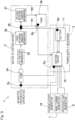
Fig. 3 is a block diagram that illustrates the concept configuration of a control system of the water filtration system; -
Fig. 4 is a block diagram of a control device of the water filtration system; -
Fig. 5 shows the relationship between power generated by photovoltaic power generation and surplus power; -
Fig. 6 is a flowchart that shows the conditions for operating a pump of the water filtration system; -
Fig. 7 is a flowchart that shows steps of a process for switching routes for to-be-treated water in the water filtration system; -
Fig. 8 is a perspective view that shows one example of installation process of the water filtration system; -
Fig. 9 is a perspective view of a water filtration system according to another embodiment of the present invention; and -
Fig. 10 is a front view that shows a water filtration system according to another embodiment of the present invention, with an openable and closable door opened. - An embodiment of the present invention is described with reference to
Fig. 1 to Fig. 8 . - As illustrated in
Fig. 1 , awater filtration system 1 according to one embodiment of the present invention includes: a water filtration device 2 (Fig. 2 ); natural energy power generators including both of awind turbine generator 7 and aphotovoltaic generator 8; apower supply mechanism 3 ofFig. 2 ; and astructure 4 which carries thewater filtration device 2, thepower generators Fig. 1 , and the power supply mechanism 3 (Fig. 2 ). Thewater filtration device 2 as shown inFig. 2 is a device that filters seawater or freshwater from rivers or the like for drinking water and/or daily use. Thepower supply mechanism 3 supplies electric power from thepower generators Fig. 1 to the load of thewater filtration device 2 as shown inFig. 2 in order to filter untreated water through thewater filtration device 2. - The
structure 4 houses thewater filtration device 2 as well as acontrol device 10 and abattery 11 of thepower supply mechanism 3. Thestructure 4 is transportable and is a robust, box-shaped structure including, for example, double doors through which thewater filtration device 2 and thepower supply mechanism 3 can be carried in and out. As illustrated inFig. 1 , thestructure 4 includes atop wall 4a and abottom wall 4b that are substantially rectangular in shape, and fourperipheral walls 4c between thetop wall 4a and thebottom wall 4b, thereby forming a generally cuboidal shape as a whole. In particular, thestructure 4 comprises a shipping container. - The "shipping container" used herein is preferably a container having a size that complies with a standard for freight transport containers - such as, for example, a domestic standard for freight containers of a country in which the container is transported. For instance, the "standard" in this context may be a standard established by a relevant domestic administrative agency in that country or an international organization such as the International Organization for Standardization (ISO), or may even be a JR container which serves as a de-facto standard for railroad freight transport containers in Japan.
- Being configured as a shipping container, the
structure 4 can be transferred using a variety of transport means such as truck, railroad, ship, and airplane. With an excellent robustness, the shipping container can also protect devices and others stored therein against possible malfunctions that may be caused by vibrations and impacts during transportation. - The
wind turbine generator 7 includes awind turbine 14 and agenerator 15 that can be driven by thewind turbine 14 to generate power. Thewind turbine 14 is configured as a vertical axis wind turbine. In particular, thewind turbine 14 includes a plurality ofblades 14a (e.g., twoblades 14a in the instant example) and ablade support 14b providing support for theblades 14a. Each of theblades 14a extends in the vertical direction, whereas theblade support 14b is supported on an upper end of atower 16 so as to be rotatable about the vertical axis by means of a bearing arrangement (not shown). The twoblades 14a are positioned angularly apart from each other by 180 degrees about the axis of thetower 16. Further, thetower 16 is secured centrally to an upper part of one of theperipheral walls 4c of thestructure 4. - The
generator 15 of thewind turbine generator 7 is disposed inside agenerator casing 17 that is attached to the top of thetower 16. Stationary race(s) of the bearing arrangement is/are fitted to thegenerator casing 17, whereas rotary race(s) of the bearing arrangement is/are coupled to theblade support 14b. Thegenerator 15 generates power as a rotor of thegenerator 15 rotates inside thegenerator casing 17 along with the rotary race(s) in response to the revolutions of thewind turbine 14. For example, an induction generator or a synchronous generator can be used for thegenerator 15. - A vertical axis wind turbine is suited as the
wind turbine 14 for use with thewind turbine generator 7 that is provided to thetransportable structure 4 in that a vertical axis wind turbine can be configured in a relatively small size but still can receive wind to generate power. Nevertheless, the wind turbine may alternatively be a horizontal axis wind turbine. - The
photovoltaic generator 8 includes asolar panel 8a that receives sunlight for photoelectric conversion and apanel mount 8b that attaches thesolar panel 8a to thestructure 4. In the instant example, thesolar panel 8a is attached onto thetop wall 4a of thestructure 4 by means of thepanel mount 8b. Depending on the direction of solar radiation or the installation environment, thesolar panel 8a may alternatively be disposed on a given one of theperipheral walls 4c of thestructure 4 or deployed around thestructure 4. Thepanel mount 8b may be equipped with a mechanism capable of changing the angle of thesolar panel 8a according to the direction of the sun. - As illustrated in
Fig. 3 , thiswater filtration device 2 includes: apump 24 that is a load; afiltration membrane 25; first and secondreverse osmosis membranes valve 28 that is a route switching module; and atank 29. Thewater filtration device 2 supplies untreated water, which is pumped up from bulk seawater or freshwater, through routes R1, R2 including pipes and the like to filter the water, and stores the filtered water in thetank 29. Thepump 24, thefiltration membrane 25, the firstreverse osmosis membrane 26, the switchingvalve 28, the secondreverse osmosis membrane 27, and thetank 29 are connected through pipes so as to be successively arranged along the direction of flow in the routes R1, R2. - The
pump 24 pumps up seawater or freshwater and forces the to-be-treated water through the routes R1, R2, while applying a pressure for reverse osmosis to the to-be-treated water at the first and secondreverse osmosis membranes filtration membrane 25 is a separation membrane that removes turbidity prior to filtration through the firstreverse osmosis membrane 26. The firstreverse osmosis membrane 26 applies a pressure equal to or greater than an osmotic pressure to one side, i.e., the high concentration side with respect to the membrane in order to separate impurities from the to-be-treated water following a treatment through thefiltration membrane 25. Thus, the firstreverse osmosis membrane 26 allows only the solvent to pass through it but not the solute (salts and the like). The secondreverse osmosis membrane 27 is equivalent to the firstreverse osmosis membrane 26. - The water following a treatment through the first
reverse osmosis membrane 26 passes through the switchingvalve 28 to be stored in thetank 29 directly or after having been filtered further through the secondreverse osmosis membrane 27. As will be discussed later, a first route R1 is used to treat freshwater, in which the water passes through the firstreverse osmosis membrane 26 and the switchingvalve 28 before it is stored in thetank 29, whereas a second route R2 is used to treat seawater, in which the water passes through the firstreverse osmosis membrane 26, the switchingvalve 28, and the secondreverse osmosis membrane 27 before it is stored in thetank 29. As the switchingvalve 28, for instance, an electromagnetic switching valve may be used which moves a spool to switch between the flow channels in response to a command from thecontrol device 10. - The
power supply mechanism 3 includes acontrol device 10 and abattery 11. Thebattery 11 stores power generated by thewind turbine generator 7 and thephotovoltaic generator 8. The stored power is supplied to thepump 24. There may be a drop in the power output from thepower generators battery 11 installed in thepower supply mechanism 3 has the storage capacity for providing power for up to several days, so that non-routine operation is possible in case of emergency. Thebattery 11 is housed in a rechargeablebattery housing box 11a to be installed inside thestructure 4, as shown inFig. 2 . - As illustrated in
Fig. 3 , thecontrol device 10 is comprised of, among other things, a computer, a program that is executed by the computer, and a variety of electronic circuits. Thecontrol device 10 applies a control to direct power generated by thepower generators battery 11 and to draw the directed power in thebattery 11 to thepump 24. By way of example, thecontrol device 10 includes an AC to DC converter that converts AC power generated by thepower generators battery 11, and an inverter that converts power stored in thebattery 11 to a sinusoidal AC wave, like that of commercial AC power, or to a square AC wave. - Now, access to natural energy is bound by constraints; energy that can be generated therefrom varies greatly between different seasons. Meanwhile, the desired amount of water to be generated has little variation throughout the year. Thus, for instance, in those seasons such as winter in which the level of power generated tends to fall, operation solely relying on natural energy can be challenging. As such, an effective measure that can be taken thereagainst is to compensate for a drop - e.g., a seasonal drop - in the level of power generated (
Fig. 9 ) through a technique which will be discussed later, or to get the most out of the time in which power generation is possible. - The
water filtration system 1 is provided with a power measuring device Sa used to measure a power consumed by thepump 24, a water level sensor Sb used to determine a level of water in thetank 29, an electrical conductivity sensor Sc used to determine an electrical conductivity of untreated water, and a voltage sensor Sd used to determine a voltage of thebattery 11. The system may be powered using the natural energy power generators. For example, a float-based level sensor that uses a float to measure the position of the liquid level of thetank 29 or a pressure-based level sensor that measures the position of the liquid level of thetank 29 on the basis of the pressure at the bottom of the vessel may be employed as the water level sensor Sb. For example, a conductivity-based concentration sensor that measures an electrolyte concentration on the basis of the conductivity of a solution may be employed as the electrical conductivity sensor Sc. - As illustrated in
Fig. 4 , thecontrol device 10 includes adeterminer unit 10a configured to determine each of the outputs from the sensors and the like, and anoperation control unit 10b. Thedeterminer unit 10a includes apower monitoring module 30, a tank waterlevel determiner module 31, a chargelevel determiner module 33, and an electricalconductivity determiner module 34. Thepower monitoring module 30 monitors the power of thepump 24 by determining the output from the power measuring device Sa constantly or regularly. The tank waterlevel determiner module 31 determines the level of water in the tank 29 (Fig. 3 ) by determining the output from the water level sensor Sb. The chargelevel determiner module 33 determines the charge level of thebattery 11 by determining the output from the voltage sensor Sd. The electricalconductivity determiner module 34 determines the electrical conductivity of the untreated water by determining the output from the electrical conductivity sensor Sc. - The
operation control unit 10b includes a pumpoperation control section 35 and a routeswitching control section 36. The pumpoperation control section 35 in the instant example controls thepump 24 to operate when the level of water determined by the tank waterlevel determiner module 31 is equal to or lower than a predetermined value and, at the same time, the charge level of thebattery 11 detected by the chargelevel determiner module 33 is equal to or higher than a threshold value (e.g., full charge). -
Fig. 5 shows the relationship between power generated by photovoltaic power generation and surplus power. The hatched area A1 inFig. 5 indicates the amount of power that is missed, and the boundary line L of the area A1 indicates the amount of power that can be produced. In general, photovoltaic power generation can only generate power during daytime, and power generation should be limited once the battery 11 (Fig. 4 ) is fully charged because the battery cannot be charged further. For example, thecontrol device 10 ofFig. 4 imposes a limitation on power generation by thepower generators 7, 8 (Fig. 3 ) once it is determined that thebattery 11 is fully charged. The expression "impose a limitation on power generation" and the like in this context may mean to stop power generation. Such a limitation on power generation leads to inefficiency, so that it is desirable to make use of the time period during which power generation is limited to actively carry out water filtration. - Specifically, the pump is operated in accordance with the flowchart shown in
Fig. 6 . This control flow is executed by the pumpoperation control section 35 ofFig. 4 . As shown inFig. 6 , once this process is started, and when the battery is fully charged or power generation is being limited (step a1: Yes), it is determined whether or not the level of water in the tank 29 (Fig. 4 ) is equal to or below a predetermined value (step a2). If the level of water is equal to or below the predetermined value (step a2: Yes), the pump is caused to operate (step a3). Then, the process returns to step a2. When it is determined in step a1 that the battery is not fully charged or power generation is not being limited (step a1: No), operation of the pump is stopped (step a4). In step a2, if the level of water exceeds the predetermined value (step a2: No), operation of the pump is stopped (step a4). Following step a4, the process returns to step a1. - It is also effective in terms of power to change the routes or the so-called filtering routes depending on untreated water, as shown in
Fig. 7 . This control ofFig. 7 is executed by the route switchingcontrol section 36 ofFig. 4 . As shown inFig. 7 , once this process is started, and if it is determined that untreated water that has been pumped up is freshwater on the basis of the determined electrical conductivity (step b1: Yes), the switching valve 28 (Fig. 3 ) is controlled to select the first route R1 (Fig. 3 ) which only passes the first reverse osmosis membrane 26 (Fig. 3 ), of the first and secondreverse osmosis membranes 26, 27 (Fig. 3 ) (step b2). Then, the process returns to step b1. When the first route R1 (Fig. 3 ) is selected, power consumption may be reduced as compared to when the second route R2 (Fig. 3 ) is selected. If it is determined that untreated water that has been pumped up is seawater on the basis of the electrical conductivity (step b1: No), the switching valve 28 (Fig. 3 ) is controlled to select the second route R2 (Fig. 3 ) which passes the first and secondreverse osmosis membranes 26, 27 (Fig. 3 ) (step b3). Then, the process returns to step b1. In this way, the route switchingcontrol section 36 of thecontrol device 10 ofFig. 4 controls the switching valve 28 (Fig. 3 ) so as to switch between the first and second routes R1, R2 (Fig. 3 ) in accordance with the electrical conductivity determined by the electricalconductivity determiner module 34. - As illustrated in
Fig. 8 , thestructure 4 housing, among others, thewater filtration device 2 and thepower supply mechanism 3 ofFig. 2 is transported to a desired installation site by, for example, a truck loader crane (or a truck-mounted crane). Then, thestructure 4 is unloaded by using acrane 32 on the truck-mounted crane. Alternatively, a forklift, a gantry crane (both not shown), etc. may be used to unload thestructure 4 from a given one of said variety of transport means. - Subsequently, the wind turbine generator and the photovoltaic generator housed in the
structure 4 are deployed out of the container and are attached to desired locations on thestructure 4. It should be noted that thestructure 4 may be transported with at least one of the wind turbine generator and the photovoltaic generator attached to the desired locations on thestructure 4. Then, each of thepower generators Fig. 1 is ready to initiate power generation so that thewater filtration system 1 can begin its operation. - The water filtration system discussed thus far permits use of the
wind turbine generator 7 and thephotovoltaic generator 8 ofFig. 1 to provide power to thepump 24 of thewater filtration device 2 ofFig. 3 , thereby making it possible to operate thewater filtration system 1 even at locations where there is no access to a grid power system. Thus, the possibilities for installation locations of thewater filtration system 1 can be increased. - The water filtration system also includes the
structure 4 ofFig. 1 which carries thewater filtration device 2, thepower generators power supply mechanism 3, thestructure 4 being transportable. Hence, thewater filtration system 1 can be transported and installed in an integrated fashion after being at least mostly assembled in a factory or the like. For this reason, it is possible to install thewater filtration system 1 more conveniently than a conventional construction which involves substantial assembling work on an installation site. As such, awater filtration system 1 which has an excellent transportability and can, therefore, lead to a reduced installation cost can be realized. - The
control device 10 ofFig. 3 causes thepump 24 to operate when thetank 29 has an unfilled volume which can be filled and, at the same time, the charge level of thebattery 11 is equal to or higher than the threshold value. Thus, thewater filtration device 2, thepower generators power supply mechanism 3 can be operated efficiently. It is also possible to actively carry out water filtration using extra power that might previously have been missed. - In addition, the routes R1, R2 for water treatment can be switched in accordance with the determined electrical conductivity, so that generated power can be effectively used.
- In the following description, the same reference numerals are used to denote features that correspond to those previously described in the respective embodiments, and overlapping description is omitted. Where only a part of a configuration is described, the rest of the configuration is to be construed as being the same as the previously described embodiments unless otherwise indicated. The same configurations provide the same effects. It is possible not only to combine the parts that have been particularly described in the respective embodiments but also to partly combine the embodiments unless there is any hindrance to such a combination.
- As illustrated in
Fig. 9 , the water filtration system may further include asolar panel 38 which is separate from thephotovoltaic generator 8 and produces power supply for the pump 24 (Fig. 3 ), which is a load. Note that, when the water filtration system includes the separatesolar panel 38, thissolar panel 38 will be secured on the ground or the like. Therefore, it may not be possible to ensure transportability of thewater filtration system 1 once an electrical connection is established between the control device 10 (seeFig. 2 ) in thestructure 4 and the separatesolar panel 38 which is secured on the ground or the like. Thus, to facilitate the transportation of thewater filtration system 1 to another location in the event of emergency, etc., the separatesolar panel 38 should be made easily removable. - Hence, the separate
solar panel 38 is configured to be releasably connected to anelectrical connection unit 39 provided to thestructure 4. Theelectrical connection unit 39 in the form of a connector is, for example, located at one of theperipheral walls 4c of thestructure 4. The connector is electrically connected to the control device 10 (Fig. 3 ) inside thestructure 4. The separatesolar panel 38 is installed to the ground through apanel mount 38b and thereby forms a so-called, field-assembled solar panel which is configured to be releasably connected to theelectrical connection unit 39 via apower cable 40. When the separatesolar panel 38 is connected to theelectrical connection unit 39, additional power can be generated. When the separatesolar panel 38 is disconnected from theelectrical connection unit 39, convenient transfer of thewater filtration system 1 can be facilitated. - The power generation unit 3 (
Fig. 3 ) may include a grid powersystem connection unit 37 that receives power supplied from agrid power system 41. This, for example, makes it possible to use thewind turbine generator 7 or thephotovoltaic generator 8 as a primary power supply while using thegrid power system 41 to compensate for temporary shortage of power generation or, alternatively, to use thegrid power system 41 as a primary power supply while utilizing thewind turbine generator 7 or thephotovoltaic generator 8 as a backup power supply in the event of a power outage, once thewater filtration system 1 is installed at a location where it can connect to thegrid power system 41. - As illustrated in
Fig. 10 , thewater filtration system 1 may further include ahydroelectric generator 19 which is capable of being installed in a water channel and capable of being housed in and removed from thestructure 4. Thishydroelectric generator 19 may include, for example, amount 20 configured to be installed in a water channel, ahydroelectric turbine 21, aframe 22 which holds thehydroelectric turbine 21, and apower generator 23 which is supported by theframe 22 and configured to generate power as thehydroelectric turbine 21 rotates. - The
water filtration system 1 including thewind turbine generator 7, thephotovoltaic generator 8 and thehydroelectric generator 19 as shown inFig. 3 can efficiently make use of natural energy according to the surrounding environment of the area in which thewater filtration system 1 is installed. The combination of multiple types of natural energy power generation makes it possible to store power in a way adapted to weather changes. Such a water filtration system also provides the same effects and advantages as the previously described embodiments. - The
water filtration system 1 may include at least one power generator selected from thewind turbine generator 7, thephotovoltaic generator 8 and thehydroelectric generator 19. - The pump
operation control section 35 of thecontrol device 10 illustrated inFig. 4 may control thepump 24 to operate when at least the condition that the level of water determined by the tank waterlevel determiner module 31 is equal to or lower than the predetermined value is satisfied. - The pump
operation control section 35 of thecontrol device 10 may control thepump 24 to operate when at least the condition that the charge level of thebattery 11 is equal to or higher than the threshold value is satisfied. - As an alternative to the shipping container, the structure may comprise a simple transportable building.
- In the case where, for example, the water filtration system is intended to be used to filter freshwater only, the second reverse osmosis membrane and the switching valve may be omitted.
- As proposed reference example, a water filtration system including a mechanism configured to automatically distinguish between freshwater and seawater is proposed. Referring to
Fig. 3 , this water filtration system may be described as follows:
A water filtration system including - a
water filtration device 2; and - a
control device 10 configured to apply a control to supply power to a load of thewater filtration device 2 to filter untreated water through thewater filtration device 2, - wherein the
water filtration device 2 includes aroute switching module 28 configured to switch routes R1, R2 through which water is treated, and - the
control device 10 includes an electrical conductivity determiner module 34 (Fig. 4 ) configured to determine an electrical conductivity of the untreated water, and is configured to control theroute switching module 28 to switch the routes R1, R2 in accordance with the electrical conductivity determined by the electrical conductivity determiner module 34 (Fig. 4 ). - Such a configuration permits automatic switching between the routes R1, R2 for water treatment in accordance with the determined electrical conductivity, i.e., depending on whether the water is freshwater or seawater, so that generated power can be effectively used.
- While configurations to carry out the present invention have thus far been described on the basis of embodiments, the embodiments disclosed herein are illustrative and not restrictive in all respects. The scope of the present invention is to be indicated by the appended claims rather than by the foregoing description, and is meant to embrace any changes made within the meaning and range of equivalency to the appended claims.
-
- 1
- water filtration system
- 2
- water filtration device
- 3
- power supply mechanism
- 4
- structure
- 7
- wind turbine generator
- 8
- photovoltaic generator
- 10
- control device
- 11
- battery
- 24
- pump (load)
- 28
- switching valve (route switching module)
- 29
- tank
- 31
- tank water level determiner module (load)
- 33
- charge level determiner module (load)
- 34
- electrical conductivity determiner module (load)
- 37
- grid power system connection unit (load)
- 38
- solar panel
- 39
- electrical connection unit
- 41
- grid power system
Claims (8)
- A water filtration system comprising:a water filtration device;at least one power generator selected from a wind turbine generator, a photovoltaic generator, and a hydroelectric generator; anda power supply mechanism configured to supply power from the power generator to a load of the water filtration device to filter untreated water through the water filtration device,wherein the water filtration system includes a structure which carries the water filtration device, the power generator, and the power supply mechanism, the structure being transportable.
- The water filtration system as claimed in claim 1, further comprising a solar panel which is separate from the photovoltaic generator and configured to produce power supply for the load, the solar panel being configured to be releasably connected to an electrical connection unit provided to the structure.
- The water filtration system as claimed in claim 1 or 2, wherein the power supply mechanism includes a grid power system connection unit configured to receive power supplied from a grid power system.
- The water filtration system as claimed in any one of claims 1 to 3, wherein the power supply mechanism includes a control device configured to apply a control to supply power generated by the power generator to the load.
- The water filtration system as claimed in claim 4, wherein the water filtration device includes a tank configured to store filtered water, and
the control device includes a tank water level determiner module configured to determine a level of water in the tank and configured to control the load to operate when the level of water determined by the tank water level determiner module is equal to or lower than a predetermined value. - The water filtration system as claimed in claim 5, wherein the power supply mechanism includes a battery configured to store power generated by the power generator and to direct the stored power to the load, and
the control device includes a charge level determiner module configured to determine a charge level of the battery and configured to control the load to operate when the charge level determined by the charge level determiner module is equal to or higher than a threshold value. - The water filtration system as claimed in any one of claims 4 to 6, wherein the water filtration device includes a route switching module configured to switch routes through which water is treated, and
the control device includes an electrical conductivity determiner module configured to determine an electrical conductivity of the untreated water and configured to control the route switching module to switch the routes in accordance with the electrical conductivity determined by the electrical conductivity determiner module. - The water filtration system as claimed in any one of claims 1 to 7, wherein the structure comprises a shipping container.
Applications Claiming Priority (2)
| Application Number | Priority Date | Filing Date | Title |
|---|---|---|---|
| JP2021109103A JP7895709B2 (en) | 2021-06-30 | 2021-06-30 | Water filtration system |
| PCT/JP2022/025020 WO2023276841A1 (en) | 2021-06-30 | 2022-06-23 | Water filtration system |
Publications (3)
| Publication Number | Publication Date |
|---|---|
| EP4365140A1 true EP4365140A1 (en) | 2024-05-08 |
| EP4365140A4 EP4365140A4 (en) | 2024-05-29 |
| EP4365140B1 EP4365140B1 (en) | 2026-02-25 |
Family
ID=84691292
Family Applications (1)
| Application Number | Title | Priority Date | Filing Date |
|---|---|---|---|
| EP22832988.4A Active EP4365140B1 (en) | 2021-06-30 | 2022-06-23 | Water filtration system |
Country Status (3)
| Country | Link |
|---|---|
| EP (1) | EP4365140B1 (en) |
| JP (1) | JP7895709B2 (en) |
| WO (1) | WO2023276841A1 (en) |
Family Cites Families (15)
| Publication number | Priority date | Publication date | Assignee | Title |
|---|---|---|---|---|
| JP2797075B2 (en) * | 1995-11-20 | 1998-09-17 | 株式会社モリタ | Vehicle mounted Shimizu manufacturing equipment |
| US7150153B2 (en) * | 2001-11-13 | 2006-12-19 | David Browe | Renewable portable stored energy power generating apparatus with alternate water source capability |
| US20070156125A1 (en) | 2005-12-30 | 2007-07-05 | Russell Delonzor | Encodable cryogenic device |
| FR2902026A1 (en) * | 2006-06-12 | 2007-12-14 | Vladimir Grcevic | MOBILE UNIT FOR THE TREATMENT OF RAW WATER |
| JP5339702B2 (en) | 2007-09-19 | 2013-11-13 | 株式会社日立製作所 | Two-way water supply system using membrane |
| JPWO2010046960A1 (en) | 2008-10-20 | 2012-03-15 | 生田 尚之 | Container type water purification system |
| JP2011098315A (en) | 2009-11-09 | 2011-05-19 | Nbl Kk | Very low cost reverse osmotic pressure fresh water generator |
| JP5737567B2 (en) | 2010-09-27 | 2015-06-17 | 東京電力株式会社 | Renewable energy multistage utilization system |
| WO2014115769A1 (en) | 2013-01-23 | 2014-07-31 | 東レ株式会社 | Method for operating freshwater production device |
| US10392269B2 (en) | 2013-10-09 | 2019-08-27 | Kevin E. Munro | Portable water purification systems with adjustable solar positioning apparatus |
| JP6284798B2 (en) | 2014-03-24 | 2018-02-28 | 協和機電工業株式会社 | Drinking water production system using solar power |
| JPWO2017085754A1 (en) | 2015-11-19 | 2018-09-06 | 株式会社テクノシステム | Mobile power generation and water purification system |
| BE1024630B1 (en) * | 2016-10-12 | 2018-05-14 | Rent A Port Utilities Naamloze Vennootschap | Device for the desalination of water by means of locally produced green energy |
| US20200346950A1 (en) | 2017-01-20 | 2020-11-05 | The Trustees Of Columbia University In The City Of New York | Renewable-powered reverse osmosis desalination with active feedwater salinity control for maximum water production efficiency with variable energy input |
| JP2020178517A (en) | 2019-04-22 | 2020-10-29 | SAIKO Innovation株式会社 | Storage battery system |
-
2021
- 2021-06-30 JP JP2021109103A patent/JP7895709B2/en active Active
-
2022
- 2022-06-23 WO PCT/JP2022/025020 patent/WO2023276841A1/en not_active Ceased
- 2022-06-23 EP EP22832988.4A patent/EP4365140B1/en active Active
Also Published As
| Publication number | Publication date |
|---|---|
| EP4365140B1 (en) | 2026-02-25 |
| JP7895709B2 (en) | 2026-07-28 |
| EP4365140A4 (en) | 2024-05-29 |
| WO2023276841A1 (en) | 2023-01-05 |
| JP2023006484A (en) | 2023-01-18 |
Similar Documents
| Publication | Publication Date | Title |
|---|---|---|
| CN105673329B (en) | Ship wind-light storage wave energy comprehensively utilizes power generator | |
| Weiner et al. | Operation experience of a solar-and wind-powered desalination demonstration plant | |
| Alawaji et al. | PV-powered water pumping and desalination plant for remote areas in Saudi Arabia | |
| US9441612B2 (en) | Transportable system for self-contained energy micro-grid with wind turbine | |
| ES2274900T3 (en) | ISOLATED NETWORK AND PROCEDURE FOR THE OPERATION OF AN ISOLATED NETWORK. | |
| CN115298436A (en) | Mobile autonomous solar wind farm | |
| RU2331789C2 (en) | Turbine plant for large-scale production of hydrogen | |
| US20130187464A1 (en) | System and Method for Portable Solar Array Deployment | |
| KR101299281B1 (en) | Solar energy and wind power system ship and the manufacturing method | |
| US20160108893A1 (en) | Portable Multiple Source Electrical Power Unit | |
| JP2013509522A (en) | Wind generator with battery unit | |
| JP2019515617A (en) | Mobile, autonomous, expandable, self-deployable, monitorable, remotely reprogrammable system for generating electrical energy | |
| Gunasekaran et al. | Technical and environmental aspects of solar photo-voltaic water pumping systems: a comprehensive survey | |
| Tzen et al. | Design and development of a hybrid autonomous system for seawater desalination | |
| EP2795113A2 (en) | Stand alone combined apparatus for electric power harvesting and potable water treatment | |
| CN121192901A (en) | Energy storage cabin with multi-source power generation intelligent switching function and control method | |
| EP4365140B1 (en) | Water filtration system | |
| CN208489813U (en) | Power supply unit and power supply system | |
| EP3446394B1 (en) | Transportable integrated stand-alone apparatus | |
| AU2021352136A1 (en) | Arrangement to optimize the production of hydrogen | |
| WO2018069810A1 (en) | Device for desalinating water by means of locally produced green energy | |
| CN115066773B (en) | Energy transmission system and wind farm | |
| EP4361362B1 (en) | Circulation-type toilet unit | |
| JP7261066B2 (en) | Portable facility with natural energy power generation unit | |
| CA2975109C (en) | Solar and wind energy collection system and method |
Legal Events
| Date | Code | Title | Description |
|---|---|---|---|
| STAA | Information on the status of an ep patent application or granted ep patent |
Free format text: STATUS: THE INTERNATIONAL PUBLICATION HAS BEEN MADE |
|
| PUAI | Public reference made under article 153(3) epc to a published international application that has entered the european phase |
Free format text: ORIGINAL CODE: 0009012 |
|
| STAA | Information on the status of an ep patent application or granted ep patent |
Free format text: STATUS: REQUEST FOR EXAMINATION WAS MADE |
|
| 17P | Request for examination filed |
Effective date: 20240125 |
|
| AK | Designated contracting states |
Kind code of ref document: A1 Designated state(s): AL AT BE BG CH CY CZ DE DK EE ES FI FR GB GR HR HU IE IS IT LI LT LU LV MC MK MT NL NO PL PT RO RS SE SI SK SM TR |
|
| A4 | Supplementary search report drawn up and despatched |
Effective date: 20240430 |
|
| RIC1 | Information provided on ipc code assigned before grant |
Ipc: C02F 103/08 20060101ALN20240424BHEP Ipc: B01D 61/12 20060101ALN20240424BHEP Ipc: B01D 61/10 20060101ALN20240424BHEP Ipc: B01D 61/04 20060101ALN20240424BHEP Ipc: B01D 61/02 20060101ALI20240424BHEP Ipc: C02F 1/00 20230101ALI20240424BHEP Ipc: C02F 1/44 20230101AFI20240424BHEP |
|
| DAV | Request for validation of the european patent (deleted) | ||
| DAX | Request for extension of the european patent (deleted) | ||
| STAA | Information on the status of an ep patent application or granted ep patent |
Free format text: STATUS: EXAMINATION IS IN PROGRESS |
|
| 17Q | First examination report despatched |
Effective date: 20241126 |
|
| GRAP | Despatch of communication of intention to grant a patent |
Free format text: ORIGINAL CODE: EPIDOSNIGR1 |
|
| STAA | Information on the status of an ep patent application or granted ep patent |
Free format text: STATUS: GRANT OF PATENT IS INTENDED |
|
| RIC1 | Information provided on ipc code assigned before grant |
Ipc: C02F 1/44 20230101AFI20250925BHEP Ipc: C02F 1/00 20230101ALI20250925BHEP Ipc: B01D 61/02 20060101ALI20250925BHEP Ipc: B01D 61/04 20060101ALN20250925BHEP Ipc: B01D 61/10 20060101ALN20250925BHEP Ipc: B01D 61/12 20060101ALN20250925BHEP Ipc: C02F 103/08 20060101ALN20250925BHEP |
|
| INTG | Intention to grant announced |
Effective date: 20251022 |
|
| GRAS | Grant fee paid |
Free format text: ORIGINAL CODE: EPIDOSNIGR3 |
|
| GRAA | (expected) grant |
Free format text: ORIGINAL CODE: 0009210 |
|
| STAA | Information on the status of an ep patent application or granted ep patent |
Free format text: STATUS: THE PATENT HAS BEEN GRANTED |
|
| AK | Designated contracting states |
Kind code of ref document: B1 Designated state(s): AL AT BE BG CH CY CZ DE DK EE ES FI FR GB GR HR HU IE IS IT LI LT LU LV MC MK MT NL NO PL PT RO RS SE SI SK SM TR |
|
| REG | Reference to a national code |
Ref country code: CH Ref legal event code: F10 Free format text: ST27 STATUS EVENT CODE: U-0-0-F10-F00 (AS PROVIDED BY THE NATIONAL OFFICE) Effective date: 20260225 Ref country code: GB Ref legal event code: FG4D |
|
| REG | Reference to a national code |
Ref country code: DE Ref legal event code: R096 Ref document number: 602022031280 Country of ref document: DE |
|
| REG | Reference to a national code |
Ref country code: IE Ref legal event code: FG4D |
|
| REG | Reference to a national code |
Ref country code: NL Ref legal event code: MP Effective date: 20260225 |
|
| PG25 | Lapsed in a contracting state [announced via postgrant information from national office to epo] |
Ref country code: RS Free format text: LAPSE BECAUSE OF FAILURE TO SUBMIT A TRANSLATION OF THE DESCRIPTION OR TO PAY THE FEE WITHIN THE PRESCRIBED TIME-LIMIT Effective date: 20260525 |
|
| PG25 | Lapsed in a contracting state [announced via postgrant information from national office to epo] |
Ref country code: ES Free format text: LAPSE BECAUSE OF FAILURE TO SUBMIT A TRANSLATION OF THE DESCRIPTION OR TO PAY THE FEE WITHIN THE PRESCRIBED TIME-LIMIT Effective date: 20260225 |
|
| PG25 | Lapsed in a contracting state [announced via postgrant information from national office to epo] |
Ref country code: PL Free format text: LAPSE BECAUSE OF FAILURE TO SUBMIT A TRANSLATION OF THE DESCRIPTION OR TO PAY THE FEE WITHIN THE PRESCRIBED TIME-LIMIT Effective date: 20260225 |
|
| PG25 | Lapsed in a contracting state [announced via postgrant information from national office to epo] |
Ref country code: GR Free format text: LAPSE BECAUSE OF FAILURE TO SUBMIT A TRANSLATION OF THE DESCRIPTION OR TO PAY THE FEE WITHIN THE PRESCRIBED TIME-LIMIT Effective date: 20260526 |
|
| REG | Reference to a national code |
Ref country code: LT Ref legal event code: MG9D |
|
| PG25 | Lapsed in a contracting state [announced via postgrant information from national office to epo] |
Ref country code: LT Free format text: LAPSE BECAUSE OF FAILURE TO SUBMIT A TRANSLATION OF THE DESCRIPTION OR TO PAY THE FEE WITHIN THE PRESCRIBED TIME-LIMIT Effective date: 20260225 |
|
| PG25 | Lapsed in a contracting state [announced via postgrant information from national office to epo] |
Ref country code: NO Free format text: LAPSE BECAUSE OF FAILURE TO SUBMIT A TRANSLATION OF THE DESCRIPTION OR TO PAY THE FEE WITHIN THE PRESCRIBED TIME-LIMIT Effective date: 20260525 |
|
| PG25 | Lapsed in a contracting state [announced via postgrant information from national office to epo] |
Ref country code: SE Free format text: LAPSE BECAUSE OF FAILURE TO SUBMIT A TRANSLATION OF THE DESCRIPTION OR TO PAY THE FEE WITHIN THE PRESCRIBED TIME-LIMIT Effective date: 20260225 Ref country code: FI Free format text: LAPSE BECAUSE OF FAILURE TO SUBMIT A TRANSLATION OF THE DESCRIPTION OR TO PAY THE FEE WITHIN THE PRESCRIBED TIME-LIMIT Effective date: 20260225 Ref country code: AT Free format text: LAPSE BECAUSE OF FAILURE TO SUBMIT A TRANSLATION OF THE DESCRIPTION OR TO PAY THE FEE WITHIN THE PRESCRIBED TIME-LIMIT Effective date: 20260225 |
|
| REG | Reference to a national code |
Ref country code: AT Ref legal event code: MK05 Ref document number: 1890709 Country of ref document: AT Kind code of ref document: T Effective date: 20260225 |
|
| PG25 | Lapsed in a contracting state [announced via postgrant information from national office to epo] |
Ref country code: HR Free format text: LAPSE BECAUSE OF FAILURE TO SUBMIT A TRANSLATION OF THE DESCRIPTION OR TO PAY THE FEE WITHIN THE PRESCRIBED TIME-LIMIT Effective date: 20260225 |
|
| PG25 | Lapsed in a contracting state [announced via postgrant information from national office to epo] |
Ref country code: PT Free format text: LAPSE BECAUSE OF FAILURE TO SUBMIT A TRANSLATION OF THE DESCRIPTION OR TO PAY THE FEE WITHIN THE PRESCRIBED TIME-LIMIT Effective date: 20260625 Ref country code: IS Free format text: LAPSE BECAUSE OF FAILURE TO SUBMIT A TRANSLATION OF THE DESCRIPTION OR TO PAY THE FEE WITHIN THE PRESCRIBED TIME-LIMIT Effective date: 20260625 |
|
| PG25 | Lapsed in a contracting state [announced via postgrant information from national office to epo] |
Ref country code: NL Free format text: LAPSE BECAUSE OF FAILURE TO SUBMIT A TRANSLATION OF THE DESCRIPTION OR TO PAY THE FEE WITHIN THE PRESCRIBED TIME-LIMIT Effective date: 20260225 |
|
| PGFP | Annual fee paid to national office [announced via postgrant information from national office to epo] |
Ref country code: FR Payment date: 20260428 Year of fee payment: 5 |
|
| PG25 | Lapsed in a contracting state [announced via postgrant information from national office to epo] |
Ref country code: LV Free format text: LAPSE BECAUSE OF FAILURE TO SUBMIT A TRANSLATION OF THE DESCRIPTION OR TO PAY THE FEE WITHIN THE PRESCRIBED TIME-LIMIT Effective date: 20260225 |
|
| PG25 | Lapsed in a contracting state [announced via postgrant information from national office to epo] |
Ref country code: BG Free format text: LAPSE BECAUSE OF FAILURE TO SUBMIT A TRANSLATION OF THE DESCRIPTION OR TO PAY THE FEE WITHIN THE PRESCRIBED TIME-LIMIT Effective date: 20260225 |