EP4365096A1 - Resin-coated aluminum-alloy drawn-and-ironed can - Google Patents
Resin-coated aluminum-alloy drawn-and-ironed can Download PDFInfo
- Publication number
- EP4365096A1 EP4365096A1 EP22892394.2A EP22892394A EP4365096A1 EP 4365096 A1 EP4365096 A1 EP 4365096A1 EP 22892394 A EP22892394 A EP 22892394A EP 4365096 A1 EP4365096 A1 EP 4365096A1
- Authority
- EP
- European Patent Office
- Prior art keywords
- barrel
- resin
- axis
- aluminum alloy
- ironed
- Prior art date
- Legal status (The legal status is an assumption and is not a legal conclusion. Google has not performed a legal analysis and makes no representation as to the accuracy of the status listed.)
- Pending
Links
Images



Classifications
-
- B—PERFORMING OPERATIONS; TRANSPORTING
- B65—CONVEYING; PACKING; STORING; HANDLING THIN OR FILAMENTARY MATERIAL
- B65D—CONTAINERS FOR STORAGE OR TRANSPORT OF ARTICLES OR MATERIALS, e.g. BAGS, BARRELS, BOTTLES, BOXES, CANS, CARTONS, CRATES, DRUMS, JARS, TANKS, HOPPERS, FORWARDING CONTAINERS; ACCESSORIES, CLOSURES, OR FITTINGS THEREFOR; PACKAGING ELEMENTS; PACKAGES
- B65D25/00—Details of other kinds or types of rigid or semi-rigid containers
- B65D25/14—Linings or internal coatings
-
- B—PERFORMING OPERATIONS; TRANSPORTING
- B65—CONVEYING; PACKING; STORING; HANDLING THIN OR FILAMENTARY MATERIAL
- B65D—CONTAINERS FOR STORAGE OR TRANSPORT OF ARTICLES OR MATERIALS, e.g. BAGS, BARRELS, BOTTLES, BOXES, CANS, CARTONS, CRATES, DRUMS, JARS, TANKS, HOPPERS, FORWARDING CONTAINERS; ACCESSORIES, CLOSURES, OR FITTINGS THEREFOR; PACKAGING ELEMENTS; PACKAGES
- B65D1/00—Rigid or semi-rigid containers having bodies formed in one piece, e.g. by casting metallic material, by moulding plastics, by blowing vitreous material, by throwing ceramic material, by moulding pulped fibrous material or by deep-drawing operations performed on sheet material
- B65D1/12—Cans, casks, barrels, or drums
- B65D1/14—Cans, casks, barrels, or drums characterised by shape
- B65D1/16—Cans, casks, barrels, or drums characterised by shape of curved cross-section, e.g. cylindrical
- B65D1/165—Cylindrical cans
-
- B—PERFORMING OPERATIONS; TRANSPORTING
- B65—CONVEYING; PACKING; STORING; HANDLING THIN OR FILAMENTARY MATERIAL
- B65D—CONTAINERS FOR STORAGE OR TRANSPORT OF ARTICLES OR MATERIALS, e.g. BAGS, BARRELS, BOTTLES, BOXES, CANS, CARTONS, CRATES, DRUMS, JARS, TANKS, HOPPERS, FORWARDING CONTAINERS; ACCESSORIES, CLOSURES, OR FITTINGS THEREFOR; PACKAGING ELEMENTS; PACKAGES
- B65D1/00—Rigid or semi-rigid containers having bodies formed in one piece, e.g. by casting metallic material, by moulding plastics, by blowing vitreous material, by throwing ceramic material, by moulding pulped fibrous material or by deep-drawing operations performed on sheet material
- B65D1/40—Details of walls
- B65D1/42—Reinforcing or strengthening parts or members
- B65D1/46—Local reinforcements, e.g. adjacent closures
-
- B—PERFORMING OPERATIONS; TRANSPORTING
- B65—CONVEYING; PACKING; STORING; HANDLING THIN OR FILAMENTARY MATERIAL
- B65D—CONTAINERS FOR STORAGE OR TRANSPORT OF ARTICLES OR MATERIALS, e.g. BAGS, BARRELS, BOTTLES, BOXES, CANS, CARTONS, CRATES, DRUMS, JARS, TANKS, HOPPERS, FORWARDING CONTAINERS; ACCESSORIES, CLOSURES, OR FITTINGS THEREFOR; PACKAGING ELEMENTS; PACKAGES
- B65D25/00—Details of other kinds or types of rigid or semi-rigid containers
- B65D25/34—Coverings or external coatings
Definitions
- the present invention relates to a drawn and ironed can made of resin-coated aluminum alloy.
- a drawn and ironed can made of resin-coated aluminum alloy (two-piece can) as a container filled with contents such as beverage.
- the drawn and ironed can made of resin-coated aluminum alloy is obtained by integrally molding the can barrel and the can bottom by, for example, the DI (drawing and ironing) process.
- a cupping and pressing step is performed to punch a circular plate out of a metal plate and draw the circular plate, and therefore to mold a shallow cup material.
- a body making step is performed to redraw the shallow cup material by moving a punch while the can material is pressed onto a redrawing die, and therefore to mold a deeper cup.
- the punch is further moved, and the cup is passed through a molding die and ironed to gradually reduce the thickness of the side wall of the cup to form a bottomed cylindrical can.
- the can is stripped from the punch by fingers and pulled out (see, for example, Patent Literature 1).
- a drawn and ironed can made of aluminum alloy which is not coated with resin is molded while the can or die is directly sprayed with a lubricant.
- the drawn and ironed can made of resin-coated aluminum alloy is molded without using a lubricant (coolant), because the resin coating serves as a lubricant (see, for example, Patent Literature 2).
- the molding process of the drawn and ironed can made of resin coated aluminum alloy does not use a lubricant, and therefore a large force may be required to pull a can out of the punch depending on conditions such as the temperature of the punch.
- a slim two-piece can having a smaller diameter has been increasingly popular because of its stylish design, instead of a general two-piece can (211 diameter) containing beer and so forth.
- the plate thickness of the can barrel has been reducing because of a request for resource saving.
- the degree of elongation is large in the height direction of the can. Therefore, the length of the can adhering to the punch is long relative to the unit length for which the fingers of the stripper hang on the opening end of the can, during the stripping in the body making step.
- the opening end of the can cannot bear the force of the stripping, and consequently the can barrel may crack.
- the present invention has been achieved considering the above-described circumstances to address the above-described problems. It is therefore an object of the invention to prevent the can barrel from cracking during the stripping.
- An aspect of the present invention provides a drawn and ironed can made of resin-coated aluminum alloy including a can body having a bottomed cylindrical shape.
- the can body includes: a can bottom; and a can barrel having a cylindrical shape around a can axis and extending from an outer circumference of the can bottom along the can axis.
- a height of the can body from a grounded part of the can bottom to an upper end of the can barrel is 151 mm to 160 mm.
- An outer diameter of the can barrel is 45 mm to 59 mm.
- the can barrel includes a tapered part formed in at least part of an area between 80 mm to 140 mm from the grounded part of the can bottom to the upper end of the can barrel.
- a plate thickness of the can barrel gradually increases inside the can barrel in the tapered part.
- An angle of the tapered part with respect to the can axis is 50 seconds to 1 minute and 30 seconds.
- Fig. 1 is a vertical cross-sectional view along a can axis O of a drawn and ironed can made of resin-coated aluminum alloy according to an embodiment of the invention, which schematically illustrates the drawn and ironed can made of resin-coated aluminum alloy.
- Fig. 1 is a diagram illustrating the shape of the cross section without the plate thickness of the can body.
- a drawn and ironed can made of resin-coated aluminum alloy 1 includes a can body 10 having a bottomed cylindrical shape.
- the can body 10 is made of resin-coated aluminum alloy.
- the resin-coated aluminum alloy includes, for example, outer coating resin which forms the outer surface of the can body 10, inner coating resin which forms the inner surface of the can body 10, and aluminum alloy provided between the outer coating resin and the inner coating resin.
- the can body 10 includes a can bottom 11, and a can barrel 12 having a cylindrical shape around a can axis O and extending from the outer circumference of the can bottom 11 along the can axis O.
- the bottomed cylindrical shape of the can body 10 is formed by the can bottom 11 and the can barrel 12.
- the can bottom 11 and the can body 12 have the same shape along the entire circumference around the can axis O.
- the can body 10 is obtained by: punching a circular plate out of a plate material made of resin-coated aluminum alloy; drawing the circular plate to mold a bottomed cylindrical cup member; redrawing and ironing the cup member to integrally mold the can bottom 11 and the can barrel 12; and trimming, necking and flanging the opening end of the can barrel 12.
- the height of the can body 10 from the grounded part (described later) of the can bottom 11 to the upper end of the can barrel 12 is 151 mm to 160 mm. With the example illustrated in Fig. 1 , the height is 155.0 mm.
- the outer diameter of the can barrel 12 is 45 mm to 59 mm. With the example illustrated in Fig. 1 , the outer diameter is 57.2 mm.
- the can bottom 11 includes a dome part 111 and an annular convex part 112.
- the dome part 111 is provided in the center of the can bottom 11, and has a concave curved surface like a dome which is concave into the inside of the can barrel 12 along the direction of the can axis O.
- the dome part 111 includes a first curved surface 111A located in the center and having a radius of curvature R1, and a second curved surface 111B located around the first curved surface and having a radius of curvature R2 different from the radius of curvature R1.
- the dome part 111 may include a plurality of curved surfaces having different radius of curvatures as the example illustrated in Fig. 1 , or may include one curved surface having a radius of curvature. Otherwise, a well-known dome shape may be applicable.
- the thickness of the outer surface coating resin is 0.008 mm to 0.015 mm
- the thickness of the aluminum alloy is 0.18 mm to 0.24 mm
- the thickness of the inner surface coating resin is 0.010 mm to 0.020 mm.
- the annular convex part 112 is formed on the outer circumference of the dome part 111 to annularly protrude to the outside of the can barrel 12 along the can axis direction, and includes a grounded part 112A.
- the grounded part 112A contacts the horizontal surface to support the can body 10.
- the tip of the annular convex part 112 may bend to the inside of the can barrel 12 in the radial direction. That is, bottom reforming as the example illustrated in Fig. 1 is applied, and therefore it is possible to improve the strength of the can bottom 11.
- the can barrel 12 has a cylindrical shape around the can axis O and extends from the outer circumference of the can bottom 11 along the can axis O.
- the can barrel 12 includes a neck 121 provided in the upper end, and a tapered part 122 provided between the upper end and the lower end.
- the neck 121 is formed such that the outer diameter of the can barrel 12 is gradually decreased toward the top of the can barrel along the can axis O.
- a can lid (not illustrated) having a diameter smaller than that of the can barrel 12 is provided in the neck 121.
- the minimum outer diameter of the neck 121 is 52.4 mm.
- the neck 121 includes a concave curved surface 121A formed on the upper end to be concave toward the outside in the radial direction and having a radius of curvature r1, a convex curved surface 121B formed on the lower end to be convex toward the outside in the radial direction and having a radius of curvature r2, and a concave curved surface 121C formed between the upper end and the lower end to be concave toward the outside in the radial direction and having a radius of curvature r3.
- the radius of curvature r1 is 1.5 mm
- the radius of curvature r2 is 5.0 mm
- the radius of curvature r3 is 10.0 mm.
- the values of the radius of curvatures are merely an example, and are by no means limiting.
- an angle ⁇ 1 formed between a straight line L1 connecting the convex curved surface 121B to the concave curved surface 121C and the straight line parallel to the can axis O is smaller than 27 degrees. With the example illustrated in Fig. 1 , the angle is 24 degrees.
- a flange 123 is formed on the opening end of the can body 10, that is, on the upper end of the neck 121.
- the distance from the upper end of the flange 123 to the lower end of the neck 121 along the direction of the can axis O is 11 mm.
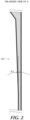
- Fig. 2 and Fig. 3 are enlarged views illustrating the tapered part 122.
- Fig. 2 is an enlarged view illustrating area A of Fig. 1
- Fig. 3 is an enlarged view illustrating area B of Fig. 1 .
- the magnification of Fig. 3 is higher than that of Fig. 2 .
- the tapered part 122 is provided at a position between 80 mm and 140 mm from the grounded part 112A (area A of Fig. 1 ) of the can bottom 11 to the upper end of the can barrel 12.
- the plate thickness of the can barrel 12 is gradually increased inside the can barrel 12 toward the top of the can barrel along the can axis O.
- the tapered part 122 is formed such that the inner surface of the can barrel 12 is inclined to the inside while the plate thickness of the can barrel is increased upward.
- the can barrel 12 is formed to have a plate thickness which gradually increases around a position of 90 mm from the grounded part 112A of the can bottom 11 toward the upper end of the can barrel 12, and further increases around a position of 135 mm to the neck 121.
- Fig. 4 illustrates the plate thickness distribution of the can body 10.
- the angle of inclination of the tapered part 122 on the inner surface of the can barrel 12, that is, an angle ⁇ 2 formed between the tapered part 122 and the straight line parallel to the can axis O is 50 seconds to 1 minute and 30 seconds.
- the angle of the tapered part 122 is optimized to slow the change in the plate thickness.
- Fig. 5 illustrates a result when a can body including a can barrel having an outer diameter of 57.2 mm is molded from a circular plate material having a blank diameter (B.D.) of 143.0 mm, while the angle of the tapered part 122 is changed from 30 seconds to 1 minute and 50 seconds by 10 seconds for each time.
- Fig. 6 illustrates a result when a can body including a can barrel having an outer diameter of 57.4 mm is molded from a circular plate material having a blank diameter (B.D.) of 143.0 mm, while the angle of the tapered part 122 is changed from 30 seconds to 1 minute and 50 seconds by 10 seconds for each time.
- the tables illustrated in Fig. 5 and Fig. 6 indicate the results when the molding speed is 300 cans per minute, and the original plate thicknesses are 0.22 mm and 0.23 mm for each of the angles of the tapered part 122. In addition, Yes means that the can barrel cracks, and No means that the can barrel does not crack.
- the numeric values of the original plate thicknesses illustrated in Fig. 5 and Fig. 6 indicate the plate thickness of the aluminum alloy, but does not include the thickness of the outer surface coating resin and the thickness of the inner surface coating resin.
- Whether or not the can barrel cracked was evaluated using the ERV (enamel rate value) method. That is, by using an enamel rater, a part to which the metal was exposed was formed in the inner surface of the molded can and an anode is connected to the part; a cathode is immersed in salt solution filled in the can, and a DC voltage of 6V was applied for 4 seconds at a temperature equal to or lower than the room temperature (23 degrees Celsius); and then the current value was evaluated. As to the evaluation criteria, it was evaluated that the can barrel did not crack when the current value was equal to or lower than 60 mA, and that the can barrel cracked when the current value is higher than 60 mA.
- ERV enamel rate value
- the can barrel cracks during the drawing or during the redrawing when the angle of the tapered part 122 is 40 seconds or less (comparative examples 1-1, 1-2, 2-1, and 2-2), or 1 minute and 40 seconds or more (comparative examples 1-8, 1-9, 2-8, and 2-9).
- the can barrel does not crack during the drawing and during the redrawing when the angle of the tapered part 122 is 50 seconds to 1 minute and 30 seconds (comparative examples 1-3 to 1-7, and 2-3 to 2-7).
- the tapered part 122 is provided to have the optimum angle with respect to the can axis, and therefore to slow the change in the plate thickness.
Landscapes
- Engineering & Computer Science (AREA)
- Mechanical Engineering (AREA)
- Ceramic Engineering (AREA)
- Containers Having Bodies Formed In One Piece (AREA)
Abstract
Description
- The present invention relates to a drawn and ironed can made of resin-coated aluminum alloy.
- There has been known a drawn and ironed can made of resin-coated aluminum alloy (two-piece can) as a container filled with contents such as beverage. The drawn and ironed can made of resin-coated aluminum alloy is obtained by integrally molding the can barrel and the can bottom by, for example, the DI (drawing and ironing) process.
- In the DI process, first, a cupping and pressing step is performed to punch a circular plate out of a metal plate and draw the circular plate, and therefore to mold a shallow cup material. Next, a body making step is performed to redraw the shallow cup material by moving a punch while the can material is pressed onto a redrawing die, and therefore to mold a deeper cup. After that, the punch is further moved, and the cup is passed through a molding die and ironed to gradually reduce the thickness of the side wall of the cup to form a bottomed cylindrical can. Next, the can is stripped from the punch by fingers and pulled out (see, for example, Patent Literature 1).
- In the above-described molding process, a drawn and ironed can made of aluminum alloy which is not coated with resin is molded while the can or die is directly sprayed with a lubricant. On the other hand, the drawn and ironed can made of resin-coated aluminum alloy is molded without using a lubricant (coolant), because the resin coating serves as a lubricant (see, for example, Patent Literature 2).
-
- PTL1:
Japanese Examined Patent Application Publication No. S60-133 - PTL2:
Japanese Patent No. 2010-75932 - As described above, the molding process of the drawn and ironed can made of resin coated aluminum alloy does not use a lubricant, and therefore a large force may be required to pull a can out of the punch depending on conditions such as the temperature of the punch.
- Incidentally, in recent years, a slim two-piece can having a smaller diameter (for example, 204 diameter) has been increasingly popular because of its stylish design, instead of a general two-piece can (211 diameter) containing beer and so forth. Moreover, the plate thickness of the can barrel has been reducing because of a request for resource saving.
- In the case of the slim can having a small diameter, the degree of elongation is large in the height direction of the can. Therefore, the length of the can adhering to the punch is long relative to the unit length for which the fingers of the stripper hang on the opening end of the can, during the stripping in the body making step. As a result, while the molding is performed at a high speed (for example, 300 cans per minute), the opening end of the can cannot bear the force of the stripping, and consequently the can barrel may crack. The smaller the plate thickness of the can barrel is, the easier it is to crack the can barrel.
- The present invention has been achieved considering the above-described circumstances to address the above-described problems. It is therefore an object of the invention to prevent the can barrel from cracking during the stripping.
- An aspect of the present invention provides a drawn and ironed can made of resin-coated aluminum alloy including a can body having a bottomed cylindrical shape. The can body includes: a can bottom; and a can barrel having a cylindrical shape around a can axis and extending from an outer circumference of the can bottom along the can axis. A height of the can body from a grounded part of the can bottom to an upper end of the can barrel is 151 mm to 160 mm. An outer diameter of the can barrel is 45 mm to 59 mm. The can barrel includes a tapered part formed in at least part of an area between 80 mm to 140 mm from the grounded part of the can bottom to the upper end of the can barrel. A plate thickness of the can barrel gradually increases inside the can barrel in the tapered part. An angle of the tapered part with respect to the can axis is 50 seconds to 1 minute and 30 seconds.
- According to the invention, it is possible to prevent the can barrel from cracking during the stripping.
-
-
Fig. 1 is a vertical cross-sectional view along a can axis of a drawn and ironed can made of resin-coated aluminum alloy according to an embodiment of the invention; -
Fig. 2 is an enlarged cross-sectional view illustrating area A of the drawn and ironed can made of resin-coated aluminum alloy ofFig. 1 according to an embodiment of the invention; -
Fig. 3 is an enlarged cross-sectional view illustrating area B of the drawn and ironed can made of resin-coated aluminum alloy ofFig. 1 according to an embodiment of the invention; -
Fig. 4 is a graph illustrating a plate thickness distribution of a can body of the drawn and ironed can made of resin-coated aluminum alloy according to an embodiment of the invention; -
Fig. 5 is a table illustrating a result when the can body is molded with various angles of a tapered part of the drawn and ironed can made of resin-coated aluminum alloy according to an embodiment of the invention; and -
Fig. 6 is a table illustrating a result when the can body is molded with various angles of the tapered part of the drawn and ironed can made of resin-coated aluminum alloy according to an embodiment of the invention. - Hereinafter, an embodiment of the invention will be described with reference to the drawings. In the description below, the same reference numbers indicate the same functional sections, and therefore repeated description for each of the drawings is omitted.
-
Fig. 1 is a vertical cross-sectional view along a can axis O of a drawn and ironed can made of resin-coated aluminum alloy according to an embodiment of the invention, which schematically illustrates the drawn and ironed can made of resin-coated aluminum alloy. Here,Fig. 1 is a diagram illustrating the shape of the cross section without the plate thickness of the can body. As illustrated inFig. 1 , a drawn and ironed can made of resin-coated aluminum alloy 1 includes acan body 10 having a bottomed cylindrical shape. - The
can body 10 is made of resin-coated aluminum alloy. The resin-coated aluminum alloy includes, for example, outer coating resin which forms the outer surface of thecan body 10, inner coating resin which forms the inner surface of thecan body 10, and aluminum alloy provided between the outer coating resin and the inner coating resin. - The
can body 10 includes acan bottom 11, and acan barrel 12 having a cylindrical shape around a can axis O and extending from the outer circumference of thecan bottom 11 along the can axis O. The bottomed cylindrical shape of thecan body 10 is formed by thecan bottom 11 and the can barrel 12. The can bottom 11 and thecan body 12 have the same shape along the entire circumference around the can axis O. Thecan body 10 is obtained by: punching a circular plate out of a plate material made of resin-coated aluminum alloy; drawing the circular plate to mold a bottomed cylindrical cup member; redrawing and ironing the cup member to integrally mold thecan bottom 11 and the can barrel 12; and trimming, necking and flanging the opening end of thecan barrel 12. - The height of the
can body 10 from the grounded part (described later) of thecan bottom 11 to the upper end of thecan barrel 12 is 151 mm to 160 mm. With the example illustrated inFig. 1 , the height is 155.0 mm. The outer diameter of thecan barrel 12 is 45 mm to 59 mm. With the example illustrated inFig. 1 , the outer diameter is 57.2 mm. - The
can bottom 11 includes adome part 111 and anannular convex part 112. Thedome part 111 is provided in the center of thecan bottom 11, and has a concave curved surface like a dome which is concave into the inside of thecan barrel 12 along the direction of the can axis O. With the example illustrated inFig. 1 , thedome part 111 includes a firstcurved surface 111A located in the center and having a radius of curvature R1, and a secondcurved surface 111B located around the first curved surface and having a radius of curvature R2 different from the radius of curvature R1. Thedome part 111 may include a plurality of curved surfaces having different radius of curvatures as the example illustrated inFig. 1 , or may include one curved surface having a radius of curvature. Otherwise, a well-known dome shape may be applicable. - In a predetermined region of the
dome part 111 including a point on the can axis O, it is preferred that the thickness of the outer surface coating resin is 0.008 mm to 0.015 mm, the thickness of the aluminum alloy is 0.18 mm to 0.24 mm, and the thickness of the inner surface coating resin is 0.010 mm to 0.020 mm. - The
annular convex part 112 is formed on the outer circumference of thedome part 111 to annularly protrude to the outside of thecan barrel 12 along the can axis direction, and includes agrounded part 112A. When thecan body 10 is placed on a horizontal surface, thegrounded part 112A contacts the horizontal surface to support thecan body 10. In the vertical cross-sectional view ofFig. 1 , the tip of the annularconvex part 112 may bend to the inside of thecan barrel 12 in the radial direction. That is, bottom reforming as the example illustrated inFig. 1 is applied, and therefore it is possible to improve the strength of thecan bottom 11. - The
can barrel 12 has a cylindrical shape around the can axis O and extends from the outer circumference of thecan bottom 11 along the can axis O. Thecan barrel 12 includes aneck 121 provided in the upper end, and atapered part 122 provided between the upper end and the lower end. - The
neck 121 is formed such that the outer diameter of thecan barrel 12 is gradually decreased toward the top of the can barrel along the can axis O. A can lid (not illustrated) having a diameter smaller than that of thecan barrel 12 is provided in theneck 121. Here, with the example illustrated inFig. 1 , the minimum outer diameter of theneck 121 is 52.4 mm. - The
neck 121 includes a concavecurved surface 121A formed on the upper end to be concave toward the outside in the radial direction and having a radius of curvature r1, a convexcurved surface 121B formed on the lower end to be convex toward the outside in the radial direction and having a radius of curvature r2, and a concavecurved surface 121C formed between the upper end and the lower end to be concave toward the outside in the radial direction and having a radius of curvature r3. - With the example illustrated in
Fig. 1 , the radius of curvature r1 is 1.5 mm, the radius of curvature r2 is 5.0 mm, and the radius of curvature r3 is 10.0 mm. However, the values of the radius of curvatures are merely an example, and are by no means limiting. In addition, it is preferred that an angle θ1 formed between a straight line L1 connecting the convexcurved surface 121B to the concavecurved surface 121C and the straight line parallel to the can axis O is smaller than 27 degrees. With the example illustrated inFig. 1 , the angle is 24 degrees. - A
flange 123 is formed on the opening end of thecan body 10, that is, on the upper end of theneck 121. With the example illustrated inFig. 1 , the distance from the upper end of theflange 123 to the lower end of theneck 121 along the direction of the can axis O is 11 mm. -
Fig. 2 andFig. 3 are enlarged views illustrating thetapered part 122.Fig. 2 is an enlarged view illustrating area A ofFig. 1 , andFig. 3 is an enlarged view illustrating area B ofFig. 1 . Here, the magnification ofFig. 3 is higher than that ofFig. 2 . - To be more specific, the
tapered part 122 is provided at a position between 80 mm and 140 mm from the groundedpart 112A (area A ofFig. 1 ) of the can bottom 11 to the upper end of thecan barrel 12. As illustrated inFig. 2 andFig. 3 , in at least part of the area A of thetapered part 122 of theFig. 1 , the plate thickness of thecan barrel 12 is gradually increased inside thecan barrel 12 toward the top of the can barrel along the can axis O. Thetapered part 122 is formed such that the inner surface of thecan barrel 12 is inclined to the inside while the plate thickness of the can barrel is increased upward. - With the example illustrated in
Fig. 2 andFig. 3 , thecan barrel 12 is formed to have a plate thickness which gradually increases around a position of 90 mm from the groundedpart 112A of the can bottom 11 toward the upper end of thecan barrel 12, and further increases around a position of 135 mm to theneck 121.Fig. 4 illustrates the plate thickness distribution of thecan body 10. - As illustrated in
Fig. 2 andFig. 3 , the angle of inclination of thetapered part 122 on the inner surface of thecan barrel 12, that is, an angle Θ2 formed between thetapered part 122 and the straight line parallel to the can axis O is 50 seconds to 1 minute and 30 seconds. In this way, even though the plate thickness of thecan body 10 is decreased, the angle of thetapered part 122 is optimized to slow the change in the plate thickness. By this means, it is possible to improve the release property during the stripping, and prevent the can barrel from cracking during the stripping. -
Fig. 5 illustrates a result when a can body including a can barrel having an outer diameter of 57.2 mm is molded from a circular plate material having a blank diameter (B.D.) of 143.0 mm, while the angle of thetapered part 122 is changed from 30 seconds to 1 minute and 50 seconds by 10 seconds for each time. In addition,Fig. 6 illustrates a result when a can body including a can barrel having an outer diameter of 57.4 mm is molded from a circular plate material having a blank diameter (B.D.) of 143.0 mm, while the angle of thetapered part 122 is changed from 30 seconds to 1 minute and 50 seconds by 10 seconds for each time. - The tables illustrated in
Fig. 5 andFig. 6 indicate the results when the molding speed is 300 cans per minute, and the original plate thicknesses are 0.22 mm and 0.23 mm for each of the angles of thetapered part 122. In addition, Yes means that the can barrel cracks, and No means that the can barrel does not crack. Here, the numeric values of the original plate thicknesses illustrated inFig. 5 andFig. 6 indicate the plate thickness of the aluminum alloy, but does not include the thickness of the outer surface coating resin and the thickness of the inner surface coating resin. - Whether or not the can barrel cracked was evaluated using the ERV (enamel rate value) method. That is, by using an enamel rater, a part to which the metal was exposed was formed in the inner surface of the molded can and an anode is connected to the part; a cathode is immersed in salt solution filled in the can, and a DC voltage of 6V was applied for 4 seconds at a temperature equal to or lower than the room temperature (23 degrees Celsius); and then the current value was evaluated. As to the evaluation criteria, it was evaluated that the can barrel did not crack when the current value was equal to or lower than 60 mA, and that the can barrel cracked when the current value is higher than 60 mA.
- Based on the tables illustrated in
Fig. 5 andFig. 6 , it is understood that the can barrel cracks during the drawing or during the redrawing when the angle of thetapered part 122 is 40 seconds or less (comparative examples 1-1, 1-2, 2-1, and 2-2), or 1 minute and 40 seconds or more (comparative examples 1-8, 1-9, 2-8, and 2-9). On the other hand, it is understood that the can barrel does not crack during the drawing and during the redrawing when the angle of thetapered part 122 is 50 seconds to 1 minute and 30 seconds (comparative examples 1-3 to 1-7, and 2-3 to 2-7). - As described above, according to the present embodiment, even though the fingers of the stripper apply the load to the opening end of the
can barrel 12 during the stripping in the body making step, thetapered part 122 is provided to have the optimum angle with respect to the can axis, and therefore to slow the change in the plate thickness. By this means, it is possible to improve the release property during the stripping, and to prevent the can barrel from cracking even though the plate thickness of the can barrel is decreased. -
- 10: can body, 11: can bottom, 12: can barrel,
- 111: dome part, 112: annular convex part
- 112A: grounded part, 121: neck,
- 121A: concave curved surface, 121B: convex curved surface,
- 121C: concave curved surface,
- 122: tapered part, 123: flange
Claims (3)
- A drawn and ironed can made of resin-coated aluminum alloy comprising a can body having a bottomed cylindrical shape,the can body including:a can bottom; anda can barrel having a cylindrical shape around a can axis and extending from an outer circumference of the can bottom along the can axis,wherein:a height of the can body from a grounded part of the can bottom to an upper end of the can barrel is 151 mm to 160 mm;an outer diameter of the can barrel is 45 mm to 59 mm;the can barrel includes a tapered part formed in at least part of an area between 80 mm to 140 mm from the grounded part of the can bottom to the upper end of the can barrel, a plate thickness of the can barrel gradually increasing inside the can barrel in the tapered part; andan angle of the tapered part with respect to the can axis is 50 seconds to 1 minute and 30 seconds.
- The drawn and ironed can made of resin-coated aluminum alloy according to claim 1, wherein:resin-coated aluminum alloy forming the can body includes outer surface coating resin which forms an outer surface of the can body, inner surface coating resin which forms an inner surface of the can body, and aluminum alloy provided between the outer surface coating resin and the inner surface coating resin;the can bottom includes a dome part having a concave curved surface provided in a center of the can bottom and being concave into an inside of the can barrel along a direction of the can axis; andin a predetermined region of the dome part including a point on the can axis, a thickness of the outer surface coating resin is 0.008 mm to 0.015 mm, a thickness of the aluminum alloy is 0.18 mm to 0.24 mm, and a thickness of the inner surface coating resin is 0.010 mm to 0.020 mm.
- The drawn and ironed can made of resin-coated aluminum alloy according to one of claims 1 and 2, wherein:the can barrel includes a neck provided in an upper end of the can barrel, the neck being formed such that the outer diameter of the can barrel is gradually decreased upward along the can axis;the neck includes at least a convex curved surface formed in a lower end of the neck and being convex toward an outside in a radial direction, and a concave curved surface formed between the lower end and an upper end of the neck and being concave toward the outside in the radial direction; andan angle of a straight line passing a top of the convex curved surface and a top of the concave surface with respect to the can axis is smaller than 27 degrees.
Applications Claiming Priority (2)
| Application Number | Priority Date | Filing Date | Title |
|---|---|---|---|
| JP2021182585A JP7835549B2 (en) | 2021-11-09 | 2021-11-09 | Resin-coated aluminum alloy squeezing can |
| PCT/JP2022/033443 WO2023084891A1 (en) | 2021-11-09 | 2022-09-06 | Resin-coated aluminum-alloy drawn-and-ironed can |
Publications (2)
| Publication Number | Publication Date |
|---|---|
| EP4365096A1 true EP4365096A1 (en) | 2024-05-08 |
| EP4365096A4 EP4365096A4 (en) | 2025-06-25 |
Family
ID=86331542
Family Applications (1)
| Application Number | Title | Priority Date | Filing Date |
|---|---|---|---|
| EP22892394.2A Pending EP4365096A4 (en) | 2021-11-09 | 2022-09-06 | Deep-drawn and ironed can with resin coating |
Country Status (5)
| Country | Link |
|---|---|
| US (1) | US20240308721A1 (en) |
| EP (1) | EP4365096A4 (en) |
| JP (1) | JP7835549B2 (en) |
| CN (1) | CN117715829B (en) |
| WO (1) | WO2023084891A1 (en) |
Family Cites Families (11)
| Publication number | Priority date | Publication date | Assignee | Title |
|---|---|---|---|---|
| JP2748856B2 (en) * | 1994-03-31 | 1998-05-13 | 東洋製罐株式会社 | Iron drawn iron can |
| JP4229650B2 (en) * | 2002-07-12 | 2009-02-25 | 大和製罐株式会社 | Bottle-shaped cans |
| JP5234267B2 (en) | 2008-09-24 | 2013-07-10 | 東洋製罐グループホールディングス株式会社 | Beverage can molding method and apparatus |
| JP2018099710A (en) * | 2016-12-20 | 2018-06-28 | ユニバーサル製缶株式会社 | DI can and bottle can |
| JP6662363B2 (en) * | 2017-07-31 | 2020-03-11 | 東洋製罐株式会社 | Can manufacturing method, apparatus for forming a three-dimensional molded part on the shoulder of a can, can, can manufacturing tool set |
| CN110997174B (en) * | 2017-07-31 | 2021-12-14 | 东洋制罐株式会社 | Can manufacturing method, can manufacturing device, can, and can manufacturing tool set |
| JP7206046B2 (en) * | 2018-02-14 | 2023-01-17 | アルテミラ製缶株式会社 | Bottle can and method for manufacturing bottle can |
| EP3939901B1 (en) * | 2019-03-14 | 2026-02-18 | Toyo Seikan Co., Ltd. | Seamless can, and resin-coated metal plate for molding seamless can |
| MX2021015688A (en) * | 2019-06-26 | 2022-04-11 | Ball Corp | A method and apparatus for sealing a metallic container with a metallic end closure. |
| JP7328847B2 (en) * | 2019-09-19 | 2023-08-17 | アルテミラ製缶株式会社 | Can bodies and product cans |
| US12240029B2 (en) * | 2021-07-27 | 2025-03-04 | Ball Corporation | Beverage container body, can end, and material therefor |
-
2021
- 2021-11-09 JP JP2021182585A patent/JP7835549B2/en active Active
-
2022
- 2022-09-06 WO PCT/JP2022/033443 patent/WO2023084891A1/en not_active Ceased
- 2022-09-06 CN CN202280051957.1A patent/CN117715829B/en active Active
- 2022-09-06 EP EP22892394.2A patent/EP4365096A4/en active Pending
-
2024
- 2024-01-30 US US18/426,873 patent/US20240308721A1/en active Pending
Also Published As
| Publication number | Publication date |
|---|---|
| EP4365096A4 (en) | 2025-06-25 |
| US20240308721A1 (en) | 2024-09-19 |
| CN117715829A (en) | 2024-03-15 |
| TW202337774A (en) | 2023-10-01 |
| WO2023084891A1 (en) | 2023-05-19 |
| JP2023070419A (en) | 2023-05-19 |
| JP7835549B2 (en) | 2026-03-25 |
| CN117715829B (en) | 2026-07-14 |
Similar Documents
| Publication | Publication Date | Title |
|---|---|---|
| US5394727A (en) | Method of forming a metal container body | |
| CN106457342B (en) | Method of forming metal bottle-shaped container | |
| US4485663A (en) | Tool for making container | |
| KR890002574B1 (en) | Process for making container | |
| GB2092985A (en) | Drawn-and-ironed metal | |
| JP2018177250A (en) | Can body and its manufacturing method | |
| US3738528A (en) | Container and a method for producing same | |
| JP2015214343A (en) | can | |
| US20240308721A1 (en) | Drawn and ironed can made of resin-coated aluminum alloy | |
| EP4620595A1 (en) | Method for producing seamless can | |
| KR890002488B1 (en) | Container manufacturing tools | |
| JP6835109B2 (en) | Manufacturing method of seamless can body and seamless can body | |
| JP2018104095A (en) | Bottle can | |
| US12611705B2 (en) | Punch, a semi-finished can, and a can manufactured with use of the said punch | |
| EP4201546A1 (en) | Preform can and method for producing same | |
| JP7328847B2 (en) | Can bodies and product cans | |
| JP7544109B2 (en) | Seamless can body and method for manufacturing seamless can body | |
| WO2021058998A1 (en) | Metal can | |
| EP4506081A1 (en) | Bottomed metal cylinder | |
| JP2020040712A (en) | Bottle can and method for manufacturing same | |
| JP2018099710A (en) | DI can and bottle can | |
| EP4741078A1 (en) | Can support member, and seamless can manufacturing method and manufacturing device | |
| JP2020001704A (en) | Bottle can and method for manufacturing the same | |
| JP2021075341A (en) | Seamless can body and method for manufacturing the same | |
| JP4472429B2 (en) | DI can manufacturing method and bottle can |
Legal Events
| Date | Code | Title | Description |
|---|---|---|---|
| STAA | Information on the status of an ep patent application or granted ep patent |
Free format text: STATUS: THE INTERNATIONAL PUBLICATION HAS BEEN MADE |
|
| PUAI | Public reference made under article 153(3) epc to a published international application that has entered the european phase |
Free format text: ORIGINAL CODE: 0009012 |
|
| STAA | Information on the status of an ep patent application or granted ep patent |
Free format text: STATUS: REQUEST FOR EXAMINATION WAS MADE |
|
| 17P | Request for examination filed |
Effective date: 20240130 |
|
| AK | Designated contracting states |
Kind code of ref document: A1 Designated state(s): AL AT BE BG CH CY CZ DE DK EE ES FI FR GB GR HR HU IE IS IT LI LT LU LV MC MK MT NL NO PL PT RO RS SE SI SK SM TR |
|
| DAV | Request for validation of the european patent (deleted) | ||
| DAX | Request for extension of the european patent (deleted) | ||
| A4 | Supplementary search report drawn up and despatched |
Effective date: 20250526 |
|
| RIC1 | Information provided on ipc code assigned before grant |
Ipc: B65D 25/34 20060101ALI20250520BHEP Ipc: B65D 1/46 20060101ALI20250520BHEP Ipc: B65D 1/16 20060101AFI20250520BHEP |