EP4365073A1 - Ship, ship controller, ship control method and program - Google Patents
Ship, ship controller, ship control method and program Download PDFInfo
- Publication number
- EP4365073A1 EP4365073A1 EP22833150.0A EP22833150A EP4365073A1 EP 4365073 A1 EP4365073 A1 EP 4365073A1 EP 22833150 A EP22833150 A EP 22833150A EP 4365073 A1 EP4365073 A1 EP 4365073A1
- Authority
- EP
- European Patent Office
- Prior art keywords
- ship
- bucket
- engine
- propulsion device
- side intermediate
- Prior art date
- Legal status (The legal status is an assumption and is not a legal conclusion. Google has not performed a legal analysis and makes no representation as to the accuracy of the status listed.)
- Withdrawn
Links
Images




Classifications
-
- B—PERFORMING OPERATIONS; TRANSPORTING
- B63—SHIPS OR OTHER WATERBORNE VESSELS; RELATED EQUIPMENT
- B63B—SHIPS OR OTHER WATERBORNE VESSELS; EQUIPMENT FOR SHIPPING
- B63B79/00—Monitoring properties or operating parameters of vessels in operation
- B63B79/40—Monitoring properties or operating parameters of vessels in operation for controlling the operation of vessels, e.g. monitoring their speed, routing or maintenance schedules
-
- B—PERFORMING OPERATIONS; TRANSPORTING
- B63—SHIPS OR OTHER WATERBORNE VESSELS; RELATED EQUIPMENT
- B63H—MARINE PROPULSION OR STEERING
- B63H11/00—Marine propulsion by water jets
- B63H11/02—Marine propulsion by water jets the propulsive medium being ambient water
- B63H11/10—Marine propulsion by water jets the propulsive medium being ambient water having means for deflecting jet or influencing cross-section thereof
- B63H11/107—Direction control of propulsive fluid
- B63H11/11—Direction control of propulsive fluid with bucket or clamshell-type reversing means
-
- B—PERFORMING OPERATIONS; TRANSPORTING
- B63—SHIPS OR OTHER WATERBORNE VESSELS; RELATED EQUIPMENT
- B63H—MARINE PROPULSION OR STEERING
- B63H21/00—Use of propulsion power plant or units on vessels
- B63H21/21—Control means for engine or transmission, specially adapted for use on marine vessels
-
- B—PERFORMING OPERATIONS; TRANSPORTING
- B63—SHIPS OR OTHER WATERBORNE VESSELS; RELATED EQUIPMENT
- B63H—MARINE PROPULSION OR STEERING
- B63H25/00—Steering; Slowing-down otherwise than by use of propulsive elements; Dynamic anchoring, i.e. positioning vessels by means of main or auxiliary propulsive elements
- B63H25/46—Steering or dynamic anchoring by jets or by rudders carrying jets
-
- B—PERFORMING OPERATIONS; TRANSPORTING
- B63—SHIPS OR OTHER WATERBORNE VESSELS; RELATED EQUIPMENT
- B63H—MARINE PROPULSION OR STEERING
- B63H21/00—Use of propulsion power plant or units on vessels
- B63H21/21—Control means for engine or transmission, specially adapted for use on marine vessels
- B63H2021/216—Control means for engine or transmission, specially adapted for use on marine vessels using electric control means
-
- B—PERFORMING OPERATIONS; TRANSPORTING
- B63—SHIPS OR OTHER WATERBORNE VESSELS; RELATED EQUIPMENT
- B63H—MARINE PROPULSION OR STEERING
- B63H25/00—Steering; Slowing-down otherwise than by use of propulsive elements; Dynamic anchoring, i.e. positioning vessels by means of main or auxiliary propulsive elements
- B63H25/46—Steering or dynamic anchoring by jets or by rudders carrying jets
- B63H2025/465—Jets or thrusters substantially used for steering or dynamic anchoring only, with means for retracting, or otherwise moving to a rest position outside the water flow around the hull
Definitions
- the present invention relates to a ship, a ship controller, a ship control method and a program.
- Patent Literature 1 a small ship having jet propulsion devices has become known (see, for example, Patent Literature 1).
- the small ship disclosed in Patent Literature 1 is conured such that a bucket is switchable between a raised position (forward position) and a lowered position (reverse position).
- a bucket is switchable between a raised position (forward position) and a lowered position (reverse position).
- the small ship heads forward because a water jet ejected from a nozzle heads toward the rear of the ship without hitting the bucket.
- the small ship When the bucket is disposed at the lowered position, the small ship heads backward because a water jet ejected from the nozzle hits the bucket and heads toward the front of the ship.
- Patent Literature 1 does not disclose control of ship fixed point holding. For this reason, it is not possible to appropriately control ship fixed point holding by the technique disclosed in Patent Literature 1.
- the jet propulsion ship disclosed in Patent Literature 2 includes a bucket that changes the direction of a jet from the jet propulsion mechanism.
- the bucket is movable between a forward position and an operating position, and the forward position is a position where the bucket is retracted from an injection port of a jet.
- the operating position is a position where the bucket faces the injection port of the j et.
- the jet propulsion ship is moved backward by disposing the bucket at a first operating position (reverse position).
- Patent Literature 2 discloses that the jet propulsion ship is held at a fixed position by disposing the bucket at a second operating position (neutral position).
- the inventors of the present invention have conducted intensive research and found that it is possible to perform control of ship fixed point holding with high accuracy even in an environment where disturbances occur by performing control of disposing a bucket at an intermediate position between a forward position and a neutral position, or at an intermediate position between a reverse position and the neutral position, and control of a rotational speed of an engine that outputs a driving force generating a jet stream.
- an object of the present invention is to provide a ship, a ship controller, a ship control method and a program which are capable of improving controllability of ship fixed point holding.
- An aspect of the present invention is a ship including an engine that outputs a driving force, a jet propulsion device that generates a propulsion force of the ship using the driving force output from the engine, a ship controller that controls the engine and the jet propulsion device, and a ship position detection unit that detects an actual ship position which is an actual position of the ship,
- the jet propulsion device includes a nozzle that ejects a jet stream generated by the driving force output from the engine, and a bucket that changes a direction of the jet stream ejected from the nozzle
- the position of the bucket includes at least a forward position where the jet propulsion device generates a propulsive force for moving the ship forward, a neutral position where the jet propulsion device does not generate a propulsive force for moving the ship, and a forward-side intermediate position between the forward position and the neutral position
- the ship controller has a ship fixed point holding mode in which feedback control of the engine and the jet propulsion device is performed based on a deviation between a target ship position,
- An aspect of the present invention is a ship including an engine that outputs a driving force, a jet propulsion device that generates a propulsion force of the ship using the driving force output from the engine, a ship controller that controls the engine and the jet propulsion device, and a ship position detection unit that detects an actual ship position which is an actual position of the ship,
- the jet propulsion device includes a nozzle that ejects a jet stream generated by the driving force output from the engine, and a bucket that changes a direction of the jet stream ejected from the nozzle
- the position of the bucket includes at least a forward position where the jet propulsion device generates a propulsive force for moving the ship forward, a neutral position where the jet propulsion device does not generate a propulsive force for moving the ship, a reverse position where the jet propulsion device generates a propulsive force for moving the ship backward, and a reverse-side intermediate position between the reverse position and the neutral position
- the ship controller has a ship fixed point holding mode in which
- An aspect of the present invention is a ship including an engine that outputs a driving force, a jet propulsion device that generates a propulsion force of the ship using the driving force output from the engine, a ship controller that controls the engine and the jet propulsion device, and a ship position detection unit that detects an actual ship position which is an actual position of the ship, in which the jet propulsion device includes a nozzle that ejects a jet stream generated by the driving force output from the engine, and a bucket that changes a direction of the jet stream ejected from the nozzle, the position of the bucket includes at least a forward position where the jet propulsion device generates a propulsive force for moving the ship forward, a neutral position where the jet propulsion device does not generate a propulsive force for moving the ship, a reverse position where the jet propulsion device generates a propulsive force for moving the ship backward, a forward-side intermediate position between the forward position and the neutral position, and a reverse-side intermediate position between the reverse position and the neutral position
- An aspect of the present invention is a ship controller included in a ship that includes an engine that outputs a driving force, a jet propulsion device that generates a propulsion force of the ship using the driving force output from the engine, and a ship position detection unit that detects an actual ship position which is an actual position of the ship, in which the jet propulsion device includes a nozzle that ejects a jet stream generated by the driving force output from the engine, and a bucket that changes a direction of the jet stream ejected from the nozzle, the position of the bucket includes at least a forward position where the jet propulsion device generates a propulsive force for moving the ship forward, a neutral position where the jet propulsion device does not generate a propulsive force for moving the ship, and a forward-side intermediate position between the forward position and the neutral position, and the ship controller has a ship fixed point holding mode in which feedback control of the engine and the jet propulsion device is performed based on a deviation between a target ship position, which is a preset target position of
- An aspect of the present invention is a ship controller included in a ship that includes an engine that outputs a driving force, a jet propulsion device that generates a propulsion force of the ship using the driving force output from the engine, and a ship position detection unit that detects an actual ship position which is an actual position of the ship, in which the jet propulsion device includes a nozzle that ejects a jet stream generated by the driving force output from the engine, and a bucket that changes a direction of the jet stream ejected from the nozzle, the position of the bucket includes at least a forward position where the jet propulsion device generates a propulsive force for moving the ship forward, a neutral position where the jet propulsion device does not generate a propulsive force for moving the ship, a reverse position where the jet propulsion device generates a propulsive force for moving the ship backward, and a reverse-side intermediate position between the reverse position and the neutral position, and the ship controller has a ship fixed point holding mode in which feedback control of the engine and the jet pro
- An aspect of the present invention is a ship controller included in a ship that includes an engine that outputs a driving force, a jet propulsion device that generates a propulsion force of the ship using the driving force output from the engine, and a ship position detection unit that detects an actual ship position which is an actual position of the ship, in which the jet propulsion device includes a nozzle that ejects a jet stream generated by the driving force output from the engine, and a bucket that changes a direction of the jet stream ejected from the nozzle, the position of the bucket includes at least a forward position where the jet propulsion device generates a propulsive force for moving the ship forward, a neutral position where the jet propulsion device does not generate a propulsive force for moving the ship, a reverse position where the jet propulsion device generates a propulsive force for moving the ship backward, a forward-side intermediate position between the forward position and the neutral position, and a reverse-side intermediate position between the reverse position and the neutral position, and the ship controller has a
- An aspect of the present invention is a ship control method of controlling a ship that includes an engine that outputs a driving force, a jet propulsion device that generates a propulsion force of the ship using the driving force output from the engine, and a ship position detection unit that detects an actual ship position which is an actual position of the ship, in which the jet propulsion device includes a nozzle that ejects a jet stream generated by the driving force output from the engine, and a bucket that changes a direction of the jet stream ejected from the nozzle, the position of the bucket includes at least a forward position where the jet propulsion device generates a propulsive force for moving the ship forward, a neutral position where the jet propulsion device does not generate a propulsive force for moving the ship, and a forward-side intermediate position between the forward position and the neutral position, the ship control method includes performing feedback control of the engine and the jet propulsion device based on a deviation between a target ship position, which is a preset target position of the ship, and the actual ship position,
- An aspect of the present invention is a ship control method of controlling a ship that includes an engine that outputs a driving force, a jet propulsion device that generates a propulsion force of the ship using the driving force output from the engine, and a ship position detection unit that detects an actual ship position which is an actual position of the ship, in which the jet propulsion device includes a nozzle that ejects a jet stream generated by the driving force output from the engine, and a bucket that changes a direction of the jet stream ejected from the nozzle, the position of the bucket includes at least a forward position where the jet propulsion device generates a propulsive force for moving the ship forward, a neutral position where the jet propulsion device does not generate a propulsive force for moving the ship, a reverse position where the jet propulsion device generates a propulsive force for moving the ship backward, and a reverse-side intermediate position between the reverse position and the neutral position, the ship control method includes performing feedback control of the engine and the jet propulsion device based on a
- An aspect of the present invention is a ship control method of controlling a ship that includes an engine that outputs a driving force, a jet propulsion device that generates a propulsion force of the ship using the driving force output from the engine, and a ship position detection unit that detects an actual ship position which is an actual position of the ship, in which the jet propulsion device includes a nozzle that ejects a jet stream generated by the driving force output from the engine, and a bucket that changes a direction of the jet stream ejected from the nozzle, the position of the bucket includes at least a forward position where the jet propulsion device generates a propulsive force for moving the ship forward, a neutral position where the jet propulsion device does not generate a propulsive force for moving the ship, a reverse position where the jet propulsion device generates a propulsive force for moving the ship backward, a forward-side intermediate position between the forward position and the neutral position, and a reverse-side intermediate position between the reverse position and the neutral position, the ship control method includes performing
- An aspect of the present invention is a program causing a computer mounted on a ship to perform feedback control of an engine and a jet propulsion device based on a deviation between a target ship position, which is a preset target position of the ship, and an actual ship position, the ship including the engine that outputs a driving force, the jet propulsion device that generates a propulsion force of the ship using the driving force output from the engine, and a ship position detection unit that detects the actual ship position which is an actual position of the ship, in which the jet propulsion device includes a nozzle that ejects a jet stream generated by the driving force output from the engine, and a bucket that changes a direction of the jet stream ejected from the nozzle, the position of the bucket includes at least a forward position where the jet propulsion device generates a propulsive force for moving the ship forward, a neutral position where the jet propulsion device does not generate a propulsive force for moving the ship, and a forward-side intermediate position between the forward position and the neutral position,
- An aspect of the present invention is a program causing a computer mounted on a ship to perform feedback control of an engine and a jet propulsion device based on a deviation between a target ship position, which is a preset target position of the ship, and an actual ship position, the ship including the engine that outputs a driving force, the jet propulsion device that generates a propulsion force of the ship using the driving force output from the engine, and a ship position detection unit that detects the actual ship position which is an actual position of the ship, in which the jet propulsion device includes a nozzle that ejects a jet stream generated by the driving force output from the engine, and a bucket that changes a direction of the jet stream ejected from the nozzle, the position of the bucket includes at least a forward position where the jet propulsion device generates a propulsive force for moving the ship forward, a neutral position where the jet propulsion device does not generate a propulsive force for moving the ship, a reverse position where the jet propulsion device generates a propuls
- An aspect of the present invention is a program causing a computer mounted on a ship to perform feedback control of an engine and a jet propulsion device based on a deviation between a target ship position, which is a preset target position of the ship, and an actual ship position, the ship including the engine that outputs a driving force, the jet propulsion device that generates a propulsion force of the ship using the driving force output from the engine, and a ship position detection unit that detects the actual ship position which is an actual position of the ship, in which the jet propulsion device includes a nozzle that ejects a jet stream generated by the driving force output from the engine, and a bucket that changes a direction of the jet stream ejected from the nozzle, the position of the bucket includes at least a forward position where the jet propulsion device generates a propulsive force for moving the ship forward, a neutral position where the jet propulsion device does not generate a propulsive force for moving the ship, a reverse position where the jet propulsion device generates a propuls
- FIG. 1 is a diagram showing an example of a ship 1 according to the first embodiment.
- the ship 1 is a PWC having the same basic functions as a personal watercraft (PWC) described with reference to FIG. 1 of Patent Document 1 or Patent Document 2, for example.
- the ship 1 includes, for example, an engine 11, a jet propulsion device 12, a ship controller 13, a ship position detection unit 14, and an operation unit 15.
- the engine 11 outputs a driving force.
- the jet propulsion device 12 generates a propulsive force for the ship 1 using the driving force output from the engine 11.
- the jet propulsion device 12 includes a nozzle 12A and a bucket 12B.
- the nozzle 12A ejects a jet stream generated by the driving force output from the engine 11.
- the bucket 12B changes the direction of the jet stream ejected from the nozzle 12A.
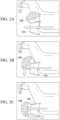
- FIGS. 2A to 2C are diagrams showing examples of configurations of the nozzle 12A and the bucket 12B.
- FIGS. 2A to 2C are diagrams showing examples of a basic position of the bucket 12B.
- FIG. 2A shows a positional relationship between the nozzle 12A and the bucket 12B and a jet stream when the bucket 12B is disposed at a forward position F.
- FIG. 2B shows a positional relationship between the nozzle 12A and the bucket 12B and a jet stream when the bucket 12B is disposed at a neutral position N.
- FIG. 2C shows a positional relationship between the nozzle 12A and the bucket 12B and a jet stream when the bucket 12B is disposed at a reverse position R.
- the bucket 12B is configured to be rotatable around a rotation center axis extending in a horizontal direction (a direction from the front side to the back side in FIG. 2A, FIG. 2B or FIG. 2C ).
- the bucket 12B may be configured to be rotatable around a rotation center axis extending in a vertical direction (the up-down direction in FIG. 2A, FIG. 2B or FIG. 2C ).
- the bucket 12B may be constituted by two members, and the two members may be configured to open right and left.
- the ship controller 13 performs control of the engine 11 and the jet propulsion device 12, and the like.
- the ship controller 13 includes, for example, a bucket position control unit 13A and an engine rotational speed control unit 13B.
- the bucket position control unit 13A controls the position of the bucket 12B (for example, control of disposing the bucket 12B at the forward position F, control of disposing the bucket 12B at the neutral position N, control of disposing the bucket 12B at the reverse position R, and the like).
- the engine rotational speed control unit 13B controls the rotational speed of the engine 11 (that is, control of changing the strength of the jet stream shown in FIG. 2A, FIG. 2B or FIG. 2C ).
- the ship position detection unit 14 detects an actual ship position, which is the actual position of the ship 1.
- the ship position detection unit 14 includes, for example, a global positioning system (GPS) device.
- GPS global positioning system
- the GPS device calculates the position coordinates of the ship 1 by receiving signals from a plurality of GPS satellites.
- the operation unit 15 receives input operations from a ship operator.
- the operation unit 15 includes a throttle operation unit 15A and a shift operation unit 15B.
- the throttle operation unit 15A is configured in the same manner as, for example, a throttle operation unit disclosed in Patent Document 2, and receives input operations from the ship operator to adjust the rotational speed of the engine 11.
- the shift operation unit 15B is configured in the same manner as, for example, a shift operation unit disclosed in Patent Document 2, and receives input operations from the ship operator to switch the position of the bucket 12B between the forward position F, the neutral position N, and the reverse position R.
- the bucket position control unit 13A controls the position of the bucket 12B to any of the forward position F, the neutral position N, and the reverse position R based on an input operation received from the ship operator by the shift operation unit 15B.
- the engine rotational speed control unit 13B controls the rotational speed of the engine 11 (control of changing the strength of the jet stream shown in FIG. 2A, FIG. 2B or FIG. 2C ) based on an input operation received from the ship operator by the throttle operation unit 15A.
- the ship controller 13 not only has the above-mentioned normal mode but also has a ship fixed point holding mode.
- the ship controller 13 performs feedback control (for example, PID control and the like) of the engine 11 and the jet propulsion device 12 based on a deviation between a target ship position, which is a preset target position of the ship 1, and the actual ship position.
- the target ship position is set in advance in accordance with, for example, an input operation of the ship operator (for example, an input operation in which the ship operator turns on a switch (not shown) when the ship 1 is located at a desired position).
- an input operation of the ship operator for example, an input operation in which the ship operator turns on a switch (not shown) when the ship 1 is located at a desired position.
- the target ship position may be set in advance, for example, by the ship operator inputting numerical values of the coordinates of a desired position of the ship 1.
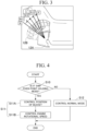
- FIG. 3 is a diagram showing an example of the position of the bucket 12B controlled by the bucket position control unit 13A of the ship controller 13 when the ship controller 13 is in a ship fixed point holding mode.
- a neutral position N when the ship controller 13 is in the ship fixed point holding mode, a neutral position N, a forward position F, and three forward-side intermediate positions N + 1, N + 2, and N + 3 located therebetween are set as the position of the bucket 12B that can be disposed by the bucket position control unit 13A of the ship controller 13.
- the position of the bucket 12B that can be disposed by the bucket position control unit 13A in the ship fixed point holding mode of the ship controller 13 includes the neutral position N, the forward-side intermediate position N + 1, the forward-side intermediate position N + 2, the forward-side intermediate position N + 3, and the forward position F.
- the three forward-side intermediate positions N + 1, N + 2, and N + 3 are set as a forward-side intermediate position between the neutral position N and the forward position F.
- any number of forward-side intermediate positions other than three may be set as the forward-side intermediate positions between the neutral position N and the forward position F.
- a rotation angle ⁇ of the bucket 12B required to move the bucket 12B from the neutral position N to the forward position F is divided into four.
- a position where the bucket 12B is rotated by ( ⁇ /4) from the neutral position N is set as the forward-side intermediate position N + 1
- a position where the bucket 12B is rotated by (2 ⁇ /4) from the neutral position N is set as the forward-side intermediate position N + 2
- a position where the bucket 12B is rotated by (3 ⁇ / 4) from the neutral position N is set as the forward-side intermediate position N + 3.
- the forward-side intermediate positions N + 1, N + 2, and N + 3 are set at the positions obtained by dividing the rotation angle ⁇ of the bucket 12B required to move the bucket 12B from the neutral position N to the forward position F at equal angular intervals.
- a rotation angle of the bucket 12B required to move the bucket 12B from the forward-side intermediate position N + 3 to the forward position F may be different from each other.
- the ship controller 13 when the ship controller 13 is in the ship fixed point holding mode, the ship controller 13 performs both control of the position of the bucket 12B (control of disposing the bucket 12B at any of the neutral position N, the forward-side intermediate positions N + 1, N + 2, and N + 3, and the forward position F) and control of the rotational speed of the engine 11.
- the ship controller 13 when the ship controller 13 is in the ship fixed point holding mode, the ship controller 13 performs control of setting the rotational speed of the engine 11 to a predetermined value so that the ship 1 is held at a fixed point of the target ship position, and setting the position of the bucket 12B to any of the forward position F, the neutral position N, and the three forward-side intermediate positions N + 1, N + 2, and N + 3.
- Table 1 shows an example of a correspondence between the rotational speed of the engine 11, the position of the bucket 12B, and the like when the ship controller 13 is in the ship fixed point holding mode.
- a control amount (feedback control amount) calculated by the ship controller 13 is zero.
- the bucket position control unit 13A of the ship controller 13 disposes the bucket 12B at the neutral position N.
- the bucket position control unit 13A controls the position of the bucket 12B to the neutral position N even when the shift operation unit 15B does not receive an input operation from the ship operator.
- the engine rotational speed control unit 13B of the ship controller 13 controls the rotational speed of the engine 11 to "IDLE" (the rotational speed of the engine 11 in an idling state).
- the engine rotational speed control unit 13B controls the rotational speed of the engine 11 to "IDLE" even when the throttle operation unit 15A does not receive an input operation from the ship operator. For this reason, the jet propulsion device 12 does not generate a propulsive force for moving the ship 1, and the ship 1 is held at the target ship position.
- the bucket position control unit 13A of the ship controller 13 disposes the bucket 12B at the forward-side intermediate position N + 1.
- the bucket position control unit 13A controls the position of the bucket 12B to the forward-side intermediate position N + 1 even when the shift operation unit 15B does not receive an input operation from the ship operator.
- the engine rotational speed control unit 13B of the ship controller 13 controls the rotational speed of the engine 11 to "IDLE".
- the engine rotational speed control unit 13B controls the rotational speed of the engine 11 to "IDLE” even when the throttle operation unit 15A does not receive an input operation from the ship operator.
- the jet propulsion device 12 generates a propulsive force for moving the ship 1 forward to reduce the deviation from "+ 1" to zero, and the ship 1 is held at the target ship position.
- the bucket position control unit 13A of the ship controller 13 disposes the bucket 12B at the forward-side intermediate position N + 2.
- the bucket position control unit 13A controls the position of the bucket 12B to the forward-side intermediate position N + 2 even when the shift operation unit 15B does not receive an input operation from the ship operator.
- the engine rotational speed control unit 13B of the ship controller 13 controls the rotational speed of the engine 11 to "IDLE".
- the engine rotational speed control unit 13B controls the rotational speed of the engine 11 to "IDLE” even when the throttle operation unit 15A does not receive an input operation from the ship operator.
- the jet propulsion device 12 generates a propulsive force for moving the ship 1 forward to reduce the deviation from "+ 2" to zero, and the ship 1 is held at the target ship position.
- the bucket position control unit 13A of the ship controller 13 disposes the bucket 12B at the forward-side intermediate position N + 3.
- the bucket position control unit 13A controls the position of the bucket 12B to the forward-side intermediate position N + 3 even when the shift operation unit 15B does not receive an input operation from the ship operator.
- the engine rotational speed control unit 13B of the ship controller 13 controls the rotational speed of the engine 11 to "IDLE".
- the engine rotational speed control unit 13B controls the rotational speed of the engine 11 to "IDLE” even when the throttle operation unit 15A does not receive an input operation from the ship operator.
- the jet propulsion device 12 generates a propulsive force for moving the ship 1 forward to reduce the deviation from "+ 3" to zero, and the ship 1 is held at the target ship position.
- the bucket position control unit 13A of the ship controller 13 disposes the bucket 12B at the forward position F.
- the bucket position control unit 13A controls the position of the bucket 12B to the forward position F even when the shift operation unit 15B does not receive an input operation from the ship operator.
- the engine rotational speed control unit 13B of the ship controller 13 controls the rotational speed of the engine 11 to "IDLE".
- the engine rotational speed control unit 13B controls the rotational speed of the engine 11 to "IDLE” even when the throttle operation unit 15A does not receive an input operation from the ship operator.
- the jet propulsion device 12 generates a propulsive force for moving the ship 1 forward to reduce the deviation from "+ 4" to zero, and the ship 1 is held at the target ship position.
- the bucket position control unit 13A of the ship controller 13 disposes the bucket 12B at the forward position F.
- the bucket position control unit 13A controls the position of the bucket 12B to the forward position F even when the shift operation unit 15B does not receive an input operation from the ship operator.
- the engine rotational speed control unit 13B of the ship controller 13 controls the rotational speed of the engine 11 to "IDLE + 1" (> the rotational speed "IDLE” of the engine 11).
- the engine rotational speed control unit 13B controls the rotational speed of the engine 11 to "IDLE + 1" even when the throttle operation unit 15A does not receive an input operation from the ship operator.
- the jet propulsion device 12 generates a propulsive force for moving the ship 1 forward to reduce the deviation from "+ 5" to zero, and the ship 1 is held at the target ship position.
- the bucket position control unit 13A of the ship controller 13 disposes the bucket 12B at the forward position F.
- the bucket position control unit 13A controls the position of the bucket 12B to the forward position F even when the shift operation unit 15B does not receive an input operation from the ship operator.
- the engine rotational speed control unit 13B of the ship controller 13 controls the rotational speed of the engine 11 to "IDLE + 2" (> the rotational speed "IDLE + 1" of the engine 11).
- the engine rotational speed control unit 13B controls the rotational speed of the engine 11 to "IDLE + 2" even when the throttle operation unit 15A does not receive an input operation from the ship operator.
- the jet propulsion device 12 generates a propulsive force for moving the ship 1 forward to reduce the deviation from "+ 6" to zero, and the ship 1 is held at the target ship position.
- the position of the bucket 12B when the actual ship position is located behind the target ship position if the position of the bucket 12B is set to be the neutral position N in the ship fixed point holding mode of the ship controller 13, and when the actual ship position is located ahead of the target ship position (that is, when a relatively small backward external force is applied to the ship 1) if the position of the bucket 12B is set to be the forward position F, the position of the bucket 12B is set to be, for example, the forward-side intermediate position N + 1, the forward-side intermediate position N + 2, the forward-side intermediate position N + 3, and the like, and the rotational speed of the engine 11 is set to "IDLE" so that the ship 1 is held at a fixed point of the target ship position.
- the forward-side intermediate positions N + 1, N + 2, and N + 3 are set as the position of the bucket 12B, and both the control of the position of the bucket 12B and control of the rotational speed of the engine 11 are performed when the ship controller 13 is in the ship fixed point holding mode.
- a deviation between the target ship position and the actual ship position is "+ 1", "+ 2", or "+ 3”
- the rotational speed of the engine 11 is controlled to "IDLE" when the position of the bucket 12B is set to be the forward-side intermediate positions N + 1, N + 2, and N + 3.
- the rotational speed of the engine 11 may be controlled to a rotational speed (for example, "IDLE + 1", “IDLE + 2", or the like) other than "IDLE".
- the rotational speed of the engine 11 may change in the order of, for example, "IDLE” ⁇ "IDLE + 1" ⁇ " IDLE + 2".
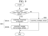
- FIG. 4 is a flowchart showing an example of processing performed by the ship controller 13 of the ship 1 according to the first embodiment.
- step S10 the ship controller 13 determines whether it is a ship fixed point holding mode (determines whether it is a ship fixed point holding mode or a normal mode).
- the processing proceeds to step S11, and when the ship controller 13 is in the normal mode, the processing proceeds to step S12.
- step S11 the ship controller 13 performs feedback control of the engine 11 and jet propulsion device 12 based on a deviation between the target ship position and the actual ship position.
- the ship controller 13 performs control of holding the ship 1 at the target ship position (performs fixed point holding of the ship 1).
- step S11A the bucket position control unit 13A of the ship controller 13 controls the position of the bucket 12B.
- the position of the bucket 12B includes the neutral position N, the forward position F, and the forward-side intermediate positions N + 1, N + 2, and N + 3.
- step S 11B the engine rotational speed control unit 13B of the ship controller 13 controls the rotational speed of the engine 11.
- step S11 when step S11 is performed, both the control of the position of the bucket 12B including the forward-side intermediate positions N + 1, N + 2, and N + 3 and the control of the rotational speed of the engine 11 are performed.
- step S12 the ship controller 13 controls the normal mode. Specifically, the bucket position control unit 13A controls the position of the bucket 12B to any of the forward position F, the neutral position N, and the reverse position R based on the ship operator's input operation received by the shift operation unit 15B.
- the engine rotational speed control unit 13B controls the rotational speed of the engine 11 based on the ship operator's input operation received by the throttle operation unit 15A.
- a ship 1 according to the second embodiment is configured in the same manner as the ship 1 according to the first embodiment described above, except for points to be described below.
- the ship 1 of the second embodiment it is possible to achieve the same effects as those of the ship 1 according to the first embodiment described above, except for points to be described below.
- the ship 1 according to the second embodiment includes, for example, an engine 11, a jet propulsion device 12, a ship controller 13, a ship position detection unit 14, and an operation unit 15.
- a bucket 12B of the jet propulsion device 12 of the ship 1 according to the second embodiment is configured to be able to be disposed at a forward position F, a neutral position N, and a reverse position R.
- a bucket position control unit 13A of the ship controller 13 of the ship 1 controls the position of the bucket 12B (for example, control of disposing the bucket 12B at the forward position F, control of disposing the bucket 12B at the neutral position N, control of disposing the bucket 12B at the reverse position R, and the like).
- An engine rotational speed control unit 13B of the ship controller 13 of the ship 1 controls the rotational speed of the engine 11 (that is, control of changing the strength of the jet stream shown in FIG. 2 ).
- the ship controller 13 of the ship 1 according to the second embodiment not only has the above-mentioned normal mode but also has a ship fixed point holding mode.
- the ship controller 13 of the ship 1 according to the second embodiment performs feedback control (for example, PID control and the like) of the engine 11 and the jet propulsion device 12 based on a deviation between a target ship position, which is a preset target position of the ship 1, and the actual ship position.
- FIG. 5 is a diagram showing the position of the bucket 12B which is controlled by the bucket position control unit 13A of the ship controller 13 when the ship controller 13 of the ship 1 according to the second embodiment is in the ship fixed point holding mode.
- a neutral position N, a forward position F, and a linear forward-side intermediate position NF that can be linearly adjusted between the neutral position N and the forward position F are set as the position of the bucket 12B that can be disposed by the bucket position control unit 13A of the ship controller 13.
- the position of the bucket 12B that can be disposed by the bucket position control unit 13A in the ship fixed point holding mode of the ship controller 13 includes the neutral position N, the forward position F, and the linear forward-side intermediate position NF that can be linearly adjusted between the neutral position N and the forward position F.
- the ship controller 13 when the ship controller 13 is in the ship fixed point holding mode, the ship controller 13 performs both control of the position of the bucket 12B (control of disposing the bucket 12B at any of the neutral position N, the linear forward-side intermediate position NF, and the forward position F) and control of the rotational speed of the engine 11.
- the ship controller 13 when the ship controller 13 is in the ship fixed point holding mode, the ship controller 13 performs control of setting the rotational speed of the engine 11 to a predetermined value so that the ship 1 is held at a fixed point of the target ship position, and setting the position of the bucket 12B to any of the forward position F, the neutral position N, and the linear forward-side intermediate position NF.
- the ship controller 13 performs control of setting the rotational speed of the engine 11 to a predetermined value so that the ship 1 is held at a fixed point of the target ship position, and setting the position of the bucket 12B to any of the forward position F, the neutral position N, and the linear forward-side intermediate position NF.
- Table 2 shows an example of a correspondence between the rotational speed of the engine 11, the position of the bucket 12B, and the like when the ship controller 13 of the ship 1 according to the second embodiment is in the ship fixed point holding mode.
- a control amount (feedback control amount) calculated by the ship controller 13 is zero when a deviation between the target ship position and the actual ship position in the ship fixed point holding mode of the ship controller 13 is zero.
- the bucket position control unit 13A of the ship controller 13 disposes the bucket 12B at the neutral position N.
- the engine rotational speed control unit 13B of the ship controller 13 controls the rotational speed of the engine 11 to "IDLE" (the rotational speed of the engine 11 in an idling state). For this reason, the jet propulsion device 12 does not generate a propulsive force for moving the ship 1, and the ship 1 is held at the target ship position.
- the bucket position control unit 13A of the ship controller 13 disposes the bucket 12B at the linear forward-side intermediate position NF.
- the bucket position control unit 13A adjusts the position of the bucket 12B to a position close to the neutral position N at the linear forward-side intermediate position NF.
- the engine rotational speed control unit 13B of the ship controller 13 controls the rotational speed of the engine 11 to "IDLE”.
- the bucket position control unit 13A of the ship controller 13 disposes the bucket 12B at the linear forward-side intermediate position NF.
- the bucket position control unit 13A adjusts the position of the bucket 12B to a position between the neutral position N at the linear forward-side intermediate positions NF and the forward position F.
- the engine rotational speed control unit 13B of the ship controller 13 controls the rotational speed of the engine 11 to "IDLE". Thereby, the jet propulsion device 12 generates a propulsive force for moving the ship 1 forward to reduce the deviation from "+ 2" to zero, and the ship 1 is held at the target ship position.
- the bucket position control unit 13A of the ship controller 13 disposes the bucket 12B at the linear forward-side intermediate position NF.
- the bucket position control unit 13A adjusts the position of the bucket 12B to a position close to the forward position F at the linear forward-side intermediate position NF.
- the engine rotational speed control unit 13B of the ship controller 13 controls the rotational speed of the engine 11 to "IDLE". Thereby, the jet propulsion device 12 generates a propulsive force for moving the ship 1 forward to reduce the deviation from "+ 3" to zero, and the ship 1 is held at the target ship position.
- the linear forward-side intermediate position NF is set as the position of the bucket 12B, and both the control of the position of the bucket 12B and control of the rotational speed of the engine 11 are performed when the ship controller 13 is in the ship fixed point holding mode.
- a deviation between the target ship position and the actual ship position is "+ 1", "+ 2", or "+ 3"
- the rotational speed of the engine 11 is controlled to "IDLE" when the position of the bucket 12B is set to be the linear forward-side intermediate position NF.
- the position of the bucket 12B is set to be the linear forward-side intermediate position NF
- the rotational speed of the engine 11 may be controlled to a rotational speed (for example, "IDLE + 1", “IDLE + 2", or the like) other than "IDLE”.
- the rotational speed of the engine 11 may change in the order of, for example, "IDLE” ⁇ "IDLE + 1" ⁇ " IDLE + 2".
- the ship 1 according to the third embodiment is configured in the same manner as the ship 1 according to the first embodiment described above, except for points to be described below.
- the ship 1 of the third embodiment it is possible to achieve the same effects as those of the ship 1 according to the first embodiment described above, except for points to be described below.
- the ship 1 according to the third embodiment includes, for example, an engine 11, a jet propulsion device 12, a ship controller 13, a ship position detection unit 14, and an operation unit 15.
- a bucket 12B of the jet propulsion device 12 of the ship 1 according to the third embodiment is configured to be able to be disposed at a forward position F, a neutral position N, and a reverse position R.
- a bucket position control unit 13A of the ship controller 13 of the ship 1 controls the position of the bucket 12B (for example, control of disposing the bucket 12B at the forward position F, control of disposing the bucket 12B at the neutral position N, control of disposing the bucket 12B at the reverse position R, and the like).
- An engine rotational speed control unit 13B of the ship controller 13 of the ship 1 controls the rotational speed of the engine 11 (that is, control of changing the strength of the jet stream shown in FIG. 2 ).
- the ship controller 13 of the ship 1 according to the third embodiment not only has the above-mentioned normal mode but also has a ship fixed point holding mode.
- the ship controller 13 of the ship 1 according to the third embodiment performs feedback control (for example, PID control and the like) of the engine 11 and the jet propulsion device 12 based on a deviation between a target ship position, which is a preset target position of the ship 1, and the actual ship position.
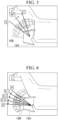
- FIG. 6 is a diagram showing an example of the position of the bucket 12B which is controlled by the bucket position control unit 13A of the ship controller 13 when the ship controller 13 of the ship 1 according to the third embodiment is in the ship fixed point holding mode.
- a neutral position N when the ship controller 13 is in the ship fixed point holding mode, a neutral position N, a reverse position R, and three reverse-side intermediate positions N - 1, N - 2, and N - 3 located therebetween are set as the position of the bucket 12B that can be disposed by the bucket position control unit 13A of the ship controller 13.
- the position of the bucket 12B that can be disposed by the bucket position control unit 13A in the ship fixed point holding mode of the ship controller 13 includes the neutral position N, the reverse-side intermediate position N - 1, the reverse-side intermediate position N - 2, the reverse-side intermediate position N - 3, and the reverse position R.
- the three reverse-side intermediate positions N - 1, N - 2, and N - 3 are set as a reverse-side intermediate position between the neutral position N and the reverse position R.
- any number of reverse-side intermediate positions other than three may be set as the reverse-side intermediate positions between the neutral position N and the reverse position R.
- a rotation angle ⁇ of the bucket 12B required to move the bucket 12B from the neutral position N to the reverse position R is divided into four.
- a position where the bucket 12B is rotated by ( ⁇ / 4) from the neutral position N is set as the reverse-side intermediate position N - 1
- a position where the bucket 12B is rotated by (2 ⁇ / 4) from the neutral position N is set as the reverse-side intermediate position N - 2
- a position where the bucket 12B is rotated by (3 ⁇ / 4) from the neutral position N is set as the reverse-side intermediate position N - 3.
- the reverse-side intermediate positions N - 1, N - 2, N - 3 are set at the positions obtained by dividing the rotation angle ⁇ of the bucket 12B required to move the bucket 12B from the neutral position N to the reverse position R at equal angular intervals.
- a rotation angle of the bucket 12B required to move the bucket 12B from the neutral position N to the reverse-side intermediate position N - 1, a rotation angle of the bucket 12B required to move the bucket 12B from the reverse-side intermediate position N - 1 to the reverse-side intermediate position N - 2, a rotation angle of the bucket 12B required to move the bucket 12B from the reverse-side intermediate position N - 2 to the reverse-side intermediate position N - 3, and a rotation angle of the bucket 12B required to move the bucket 12B from the reverse-side intermediate position N - 3 to the reverse position R may be different from each other.
- the ship controller 13 when the ship controller 13 is in the ship fixed point holding mode, the ship controller 13 performs both control of the position of the bucket 12B (control of disposing the bucket 12B at any of the neutral position N, the reverse-side intermediate positions N - 1, N - 2, and N - 3, and the reverse position R) and control of the rotational speed of the engine 11.
- the ship controller 13 when the ship controller 13 is in the ship fixed point holding mode, the ship controller 13 performs control of setting the rotational speed of the engine 11 to a predetermined value so that the ship 1 is held at a fixed point of the target ship position, and setting the position of the bucket 12B to any of the reverse position R, the neutral position N, and the three reverse-side intermediate positions N - 1, N - 2, and N - 3.
- the ship controller 13 performs control of setting the rotational speed of the engine 11 to a predetermined value so that the ship 1 is held at a fixed point of the target ship position, and setting the position of the bucket 12B to any of the reverse position R, the neutral position N, and the three reverse-side intermediate positions N - 1, N - 2, and N - 3.
- Table 3 Deviation ... -6 -5 -4 -3 -2 -1 0 Control amount ... -6 -5 -4 -3 -2 N-1 N Engine rotational speed ... IDLE+2 IDLE+1 IDLE IDLE IDLE IDLE IDLE
- Table 3 shows an example of a correspondence between the rotational speed of the engine 11, the position of the bucket 12B, and the like when the ship controller 13 of the ship 1 according to the third embodiment is in the ship fixed point holding mode.
- a control amount (feedback control amount) calculated by the ship controller 13 is zero when a deviation between the target ship position and the actual ship position in the ship fixed point holding mode of the ship controller 13 is zero.
- the bucket position control unit 13A of the ship controller 13 disposes the bucket 12B at the neutral position N.
- the bucket position control unit 13A controls the position of the bucket 12B to the neutral position N even when the shift operation unit 15B does not receive an input operation from the ship operator.
- the engine rotational speed control unit 13B of the ship controller 13 controls the rotational speed of the engine 11 to "IDLE" (the rotational speed of the engine 11 in an idling state).
- the engine rotational speed control unit 13B controls the rotational speed of the engine 11 to "IDLE" even when the throttle operation unit 15A does not receive an input operation from the ship operator. For this reason, the jet propulsion device 12 does not generate a propulsive force for moving the ship 1, and the ship 1 is held at the target ship position.
- the bucket position control unit 13A of the ship controller 13 disposes the bucket 12B at the reverse-side intermediate position N - 1.
- the bucket position control unit 13A controls the position of the bucket 12B to the reverse-side intermediate position N - 1 even when the shift operation unit 15B does not receive an input operation from the ship operator.
- the engine rotational speed control unit 13B of the ship controller 13 controls the rotational speed of the engine 11 to "IDLE".
- the engine rotational speed control unit 13B controls the rotational speed of the engine 11 to "IDLE” even when the throttle operation unit 15A does not receive an input operation from the ship operator.
- the jet propulsion device 12 generates a propulsive force for moving the ship 1 backward to reduce the deviation from "- 1" to zero, and the ship 1 is held at the target ship position.
- the bucket position control unit 13A of the ship controller 13 disposes the bucket 12B at the reverse-side intermediate position N - 2.
- the bucket position control unit 13A controls the position of the bucket 12B to the reverse-side intermediate position N - 2 even when the shift operation unit 15B does not receive an input operation from the ship operator.
- the engine rotational speed control unit 13B of the ship controller 13 controls the rotational speed of the engine 11 to "IDLE".
- the engine rotational speed control unit 13B controls the rotational speed of the engine 11 to "IDLE” even when the throttle operation unit 15A does not receive an input operation from the ship operator.
- the jet propulsion device 12 generates a propulsive force for moving the ship 1 backward to reduce the deviation from "- 2" to zero, and the ship 1 is held at the target ship position.
- the bucket position control unit 13A of the ship controller 13 disposes the bucket 12B at the reverse-side intermediate position N - 3.
- the bucket position control unit 13A controls the position of the bucket 12B to the reverse-side intermediate position N - 3 even when the shift operation unit 15B does not receive an input operation from the ship operator.
- the engine rotational speed control unit 13B of the ship controller 13 controls the rotational speed of the engine 11 to "IDLE".
- the engine rotational speed control unit 13B controls the rotational speed of the engine 11 to "IDLE” even when the throttle operation unit 15A does not receive an input operation from the ship operator.
- the jet propulsion device 12 generates a propulsive force for moving the ship 1 backward to reduce the deviation from "- 3" to zero, and the ship 1 is held at the target ship position.
- the bucket position control unit 13A of the ship controller 13 disposes the bucket 12B at the reverse position R.
- the bucket position control unit 13A controls the position of the bucket 12B to the reverse position R even when the shift operation unit 15B does not receive an input operation from the ship operator.
- the engine rotational speed control unit 13B of the ship controller 13 controls the rotational speed of the engine 11 to "IDLE”.
- the engine rotational speed control unit 13B controls the rotational speed of the engine 11 to "IDLE" even when the throttle operation unit 15A does not receive an input operation from the ship operator. Thereby, the jet propulsion device 12 generates a propulsive force for moving the ship 1 backward to reduce the deviation from "- 4" to zero, and the ship 1 is held at the target ship position.
- the bucket position control unit 13A of the ship controller 13 disposes the bucket 12B at the reverse position R.
- the bucket position control unit 13A controls the position of the bucket 12B to the reverse position R even when the shift operation unit 15B does not receive an input operation from the ship operator.
- the engine rotational speed control unit 13B of the ship controller 13 controls the rotational speed of the engine 11 to "IDLE + 1" (> the rotational speed "IDLE” of the engine 11).
- the engine rotational speed control unit 13B controls the rotational speed of the engine 11 to "IDLE + 1" even when the throttle operation unit 15A does not receive an input operation from the ship operator.
- the jet propulsion device 12 generates a propulsive force for moving the ship 1 backward to reduce the deviation from "- 5" to zero, and the ship 1 is held at the target ship position.
- the bucket position control unit 13A of the ship controller 13 disposes the bucket 12B at the reverse position R.
- the bucket position control unit 13A controls the position of the bucket 12B to the reverse position R even when the shift operation unit 15B does not receive an input operation from the ship operator.
- the engine rotational speed control unit 13B of the ship controller 13 controls the rotational speed of the engine 11 to "IDLE + 2" (> the rotational speed "IDLE + 1" of the engine 11).
- the engine rotational speed control unit 13B controls the rotational speed of the engine 11 to "IDLE + 2" even when the throttle operation unit 15A does not receive an input operation from the ship operator.
- the jet propulsion device 12 generates a propulsive force for moving the ship 1 backward to reduce the deviation from "- 6" to zero, and the ship 1 is held at the target ship position.
- the reverse-side intermediate positions N - 1, N - 2, and N - 3 are set as the position of the bucket 12B, and both the control of the position of the bucket 12B and control of the rotational speed of the engine 11 are performed when the ship controller 13 is in the ship fixed point holding mode.
- a deviation between the target ship position and the actual ship position is "- 1", "- 2", or "-3 ", it is possible to prevent the ship 1 from excessively moving to the rear side of the target ship position due to the bucket 12B being disposed at the reverse position R.
- the rotational speed of the engine 11 is controlled to "IDLE" when the position of the bucket 12B is set to be the reverse-side intermediate positions N - 1, N - 2, and N - 3.
- the rotational speed of the engine 11 may be controlled to a rotational speed (for example, "IDLE + 1", “IDLE + 2", or the like) other than "IDLE”.
- the rotational speed of the engine 11 may change in the order of, for example, "IDLE” --7 "IDLE + 1" --7 " IDLE + 2".
- FIG. 7 is a flowchart showing an example of processing performed by the ship controller 13 of the ship 1 according to the third embodiment.
- step S30 the ship controller 13 determines whether it is a ship fixed point holding mode (determines whether it is a ship fixed point holding mode or a normal mode).
- the processing proceeds to step S31, and when the ship controller 13 is in the normal mode, the processing proceeds to step S32.
- step S31 the ship controller 13 performs feedback control of the engine 11 and jet propulsion device 12 based on a deviation between the target ship position and the actual ship position.
- the ship controller 13 performs control of holding the ship 1 at the target ship position (performs fixed point holding of the ship 1).
- step S31A the bucket position control unit 13A of the ship controller 13 controls the position of the bucket 12B.
- the position of the bucket 12B includes the neutral position N, the reverse position R, and the reverse-side intermediate positions N - 1, N - 2, and N - 3.
- step S31B the engine rotational speed control unit 13B of the ship controller 13 controls the rotational speed of the engine 11.
- step S31 when step S31 is performed, both the control of the position of the bucket 12B including the reverse-side intermediate positions N - 1, N - 2, and N - 3 and the control of the rotational speed of the engine 11 are performed.
- step S32 the ship controller 13 controls the normal mode. Specifically, the bucket position control unit 13A controls the position of the bucket 12B to any of the forward position F, the neutral position N, and the reverse position R based on the ship operator's input operation received by the shift operation unit 15B.
- the engine rotational speed control unit 13B controls the rotational speed of the engine 11 based on the ship operator's input operation received by the throttle operation unit 15A.
- a ship 1 according to the fourth embodiment is configured in the same manner as the ship 1 according to the first embodiment described above, except for points to be described below.
- the ship 1 of the fourth embodiment it is possible to achieve the same effects as those of the ship 1 according to the first embodiment described above, except for points to be described below.
- the ship 1 according to the fourth embodiment includes, for example, an engine 11, a jet propulsion device 12, a ship controller 13, a ship position detection unit 14, and an operation unit 15.
- a bucket 12B of the jet propulsion device 12 of the ship 1 according to the fourth embodiment is configured to be able to be disposed at a forward position F, a neutral position N, and a reverse position R.
- a bucket position control unit 13A of the ship controller 13 of the ship 1 controls the position of the bucket 12B (for example, control of disposing the bucket 12B at the forward position F, control of disposing the bucket 12B at the neutral position N, control of disposing the bucket 12B at the reverse position R, and the like).
- An engine rotational speed control unit 13B of the ship controller 13 of the ship 1 controls the rotational speed of the engine 11 (that is, control of changing the strength of the jet stream shown in FIG. 2 ).
- the ship controller 13 of the ship 1 according to the fourth embodiment not only has the above-mentioned normal mode but also has a ship fixed point holding mode.
- the ship controller 13 of the ship 1 according to the fourth embodiment performs feedback control (for example, PID control and the like) of the engine 11 and the jet propulsion device 12 based on a deviation between a target ship position, which is a preset target position of the ship 1, and the actual ship position.
- FIG. 8 is a diagram showing the position of the bucket 12B which is controlled by the bucket position control unit 13A of the ship controller 13 when the ship controller 13 of the ship 1 according to the fourth embodiment is in the ship fixed point holding mode.
- a neutral position N when the ship controller 13 is in the ship fixed point holding mode, a neutral position N, a reverse position R, and a linear reverse-side intermediate position NR that can be linearly adjusted between the neutral position N and the reverse position R are set as the position of the bucket 12B that can be disposed by the bucket position control unit 13A of the ship controller 13.
- the position of the bucket 12B that can be disposed by the bucket position control unit 13A in the ship fixed point holding mode of the ship controller 13 includes the neutral position N, the reverse position R, and the linear reverse-side intermediate position NR that can be linearly adjusted between the neutral position N and the reverse position R.
- the ship controller 13 when the ship controller 13 is in the ship fixed point holding mode, the ship controller 13 performs both control of the position of the bucket 12B (control of disposing the bucket 12B at any of the neutral position N, the linear reverse-side intermediate position NR, and the reverse position R) and control of the rotational speed of the engine 11.
- the ship controller 13 when the ship controller 13 is in the ship fixed point holding mode, the ship controller 13 performs control of setting the rotational speed of the engine 11 to a predetermined value so that the ship 1 is held at a fixed point of the target ship position, and setting the position of the bucket 12B to any of the reverse position R, the neutral position N, and the linear reverse-side intermediate position NR.
- Table 4 Deviation ... -6 -5 -4 -3 -2 -1 0 Control amount ... -6 -5 -4 -3 -2 -1 0 Bucket position ... R R R NR NR NR N Engine rotational speed ... IDLE+2 IDLE+1 IDLE IDLE IDLE IDLE IDLE
- Table 4 shows an example of a correspondence between the rotational speed of the engine 11, the position of the bucket 12B, and the like when the ship controller 13 of the ship 1 according to the fourth embodiment is in the ship fixed point holding mode.
- a control amount (feedback control amount) calculated by the ship controller 13 is zero when a deviation between the target ship position and the actual ship position in the ship fixed point holding mode of the ship controller 13 is zero.
- the bucket position control unit 13A of the ship controller 13 disposes the bucket 12B at the neutral position N.
- the engine rotational speed control unit 13B of the ship controller 13 controls the rotational speed of the engine 11 to "IDLE" (the rotational speed of the engine 11 in an idling state). For this reason, the jet propulsion device 12 does not generate a propulsive force for moving the ship 1, and the ship 1 is held at the target ship position.
- the bucket position control unit 13A of the ship controller 13 disposes the bucket 12B at the linear reverse-side intermediate position NR.
- the bucket position control unit 13A adjusts the position of the bucket 12B to a position close to the neutral position N at the linear reverse-side intermediate position NR.
- the engine rotational speed control unit 13B of the ship controller 13 controls the rotational speed of the engine 11 to "IDLE”.
- the bucket position control unit 13A of the ship controller 13 disposes the bucket 12B at the linear reverse-side intermediate position NR.
- the bucket position control unit 13A adjusts the position of the bucket 12B to a position between the neutral position N at the linear reverse-side intermediate position NR and the reverse position R.
- the engine rotational speed control unit 13B of the ship controller 13 controls the rotational speed of the engine 11 to "IDLE". Thereby, the jet propulsion device 12 generates a propulsive force for moving the ship 1 backward to reduce the deviation from "- 2" to zero, and the ship 1 is held at the target ship position.
- the bucket position control unit 13A of the ship controller 13 disposes the bucket 12B at the linear reverse-side intermediate position NR.
- the bucket position control unit 13A adjusts the position of the bucket 12B to a position close to the reverse position R at the linear reverse-side intermediate position NR.
- the engine rotational speed control unit 13B of the ship controller 13 controls the rotational speed of the engine 11 to "IDLE”.
- the linear reverse-side intermediate position NR is set as the position of the bucket 12B, and both the control of the position of the bucket 12B and control of the rotational speed of the engine 11 are performed when the ship controller 13 is in the ship fixed point holding mode.
- a deviation between the target ship position and the actual ship position is "- 1", "-2", or "-3"
- the rotational speed of the engine 11 is controlled to "IDLE" when the position of the bucket 12B is set to be the linear reverse-side intermediate position NR.
- the rotational speed of the engine 11 may be controlled to a rotational speed (for example, "IDLE + 1 ", "IDLE + 2", or the like) other than "IDLE”.
- the rotational speed of the engine 11 may change in the order of, for example, "IDLE” ⁇ "IDLE + 1" ----+ " IDLE + 2".
- a ship 1 according to the fifth embodiment is configured in the same manner as the ship 1 according to the first embodiment described above, except for points to be described below.
- the ship 1 of the fifth embodiment it is possible to achieve the same effects as those of the ship 1 according to the first embodiment described above, except for points to be described below.
- the ship 1 according to the fifth embodiment includes, for example, an engine 11, a jet propulsion device 12, a ship controller 13, a ship position detection unit 14, and an operation unit 15.
- a bucket 12B of the jet propulsion device 12 of the ship 1 according to the fifth embodiment is configured to be able to be disposed at a forward position F, a neutral position N, and a reverse position R.
- a bucket position control unit 13A of the ship controller 13 of the ship 1 controls the position of the bucket 12B (for example, control of disposing the bucket 12B at the forward position F, control of disposing the bucket 12B at the neutral position N, control of disposing the bucket 12B at the reverse position R, and the like).
- An engine rotational speed control unit 13B of the ship controller 13 of the ship 1 controls the rotational speed of the engine 11 (that is, control of changing the strength of the jet stream shown in FIG. 2 ).
- the ship controller 13 of the ship 1 according to the fifth embodiment not only has the above-mentioned normal mode but also has a ship fixed point holding mode.
- the ship controller 13 of the ship 1 according to the fifth embodiment performs feedback control (for example, PID control and the like) of the engine 11 and the jet propulsion device 12 based on a deviation between a target ship position, which is a preset target position of the ship 1, and the actual ship position.
- a forward position F (see FIG. 3 ), a neutral position N (see FIGS. 3 and 6 ), three forward-side intermediate positions N + 1, N + 2, and N + 3 (see FIG. 3 ) located between the forward position F and the neutral position N, a reverse position R (see FIG. 6 ), and three reverse-side intermediate positions N - 1, N - 2, and N - 3 (see FIG. 6 ) located between the neutral position N and the reverse position R are set as the position of the bucket 12B that can be disposed by the bucket position control unit 13A of the ship controller 13.
- the three forward-side intermediate positions N + 1, N + 2, and N + 3 are set as a forward-side intermediate position between the neutral position N and the forward position F.
- any number of forward-side intermediate positions other than three may be set as a forward-side intermediate position between the neutral position N and the forward position F.
- three reverse-side intermediate positions N - 1, N - 2, and N - 3 are set as a reverse-side intermediate position between the neutral position N and the reverse position R.
- any number of reverse-side intermediate positions other than three may be set as a reverse-side intermediate position between the neutral position N and the reverse position R.
- a rotation angle ⁇ of the bucket 12B required to move the bucket 12B from the neutral position N to the forward position F is divided into four.
- a position where the bucket 12B is rotated by ( ⁇ / 4) from the neutral position N is set as the forward-side intermediate position N + 1
- a position where the bucket 12B is rotated by (2 ⁇ / 4) from the neutral position N is set as the forward-side intermediate position N + 2
- a position where the bucket 12B is rotated by (3 ⁇ / 4) from the neutral position N is set as the forward-side intermediate position N + 3.
- the forward-side intermediate positions N + 1, N + 2, and N + 3 are set at the positions obtained by dividing the rotation angle ⁇ of the bucket 12B required to move the bucket 12B from the neutral position N to the forward position F at equal angular intervals.
- a rotation angle of the bucket 12B required to move the bucket 12B from the forward-side intermediate position N + 3 to the forward position F may be different from each other.
- a rotation angle ⁇ of the bucket 12B required to move the bucket 12B from the neutral position N to the reverse position R is divided into four.
- a position where the bucket 12B is rotated by ( ⁇ / 4) from the neutral position N is set as the reverse-side intermediate position N - 1
- a position where the bucket 12B is rotated by (2 ⁇ / 4) from the neutral position N is set as the reverse-side intermediate position N - 2
- a position where the bucket 12B is rotated by (3 ⁇ / 4) from the neutral position N is set as the reverse-side intermediate position N - 3.
- the reverse-side intermediate positions N - 1, N - 2, N - 3 are set at the positions obtained by dividing the rotation angle ⁇ of the bucket 12B required to move the bucket 12B from the neutral position N to the reverse position R at equal angular intervals.
- a rotation angle of the bucket 12B required to move the bucket 12B from the neutral position N to the reverse-side intermediate position N - 1 a rotation angle of the bucket 12B required to move the bucket 12B from the reverse-side intermediate position N - 1 to the reverse-side intermediate position N - 2
- a rotation angle of the bucket 12B required to move the bucket 12B from the reverse-side intermediate position N - 3 to the reverse position R may be different from each other.
- the ship controller 13 when the ship controller 13 is in the ship fixed point holding mode, the ship controller 13 performs both control of the position of the bucket 12B (control of disposing the bucket 12B at any of the forward position F, the forward-side intermediate positions N + 1, N + 2, and N + 3, the neutral position N, the reverse-side intermediate positions N - 1, N - 2, and N - 3, and the reverse position R) and control of the rotational speed of the engine 11.
- the ship controller 13 when the ship controller 13 is in the ship fixed point holding mode, the ship controller 13 performs control of setting the rotational speed of the engine 11 to a predetermined value so that the ship 1 is held at a fixed point of the target ship position, and setting the position of the bucket 12B to any of the forward position F, the three forward-side intermediate positions N + 1, N + 2, and N + 3, the neutral position N, the three reverse-side intermediate positions N - 1, N - 2, and N - 3, and the reverse position R.
- Table 5 Deviation ... -6 -5 -4 -3 -2 -1 0 Control amount ... -6 -5 -4 -3 -2 -1 0 Bucket position ... R R R N-3 N-2 N-1 N Engine rotational speed ...
- Table 5 shows an example of a correspondence between the rotational speed of the engine 11, the position of the bucket 12B, and the like when the ship controller 13 is in the ship fixed point holding mode.
- the engine rotational speed control unit 13B controls the rotational speed of the engine 11 to "IDLE + 1" even when the throttle operation unit 15A does not receive an input operation from the ship operator. Thereby, the jet propulsion device 12 generates a propulsive force for moving the ship 1 forward to reduce the deviation from "+ 5" to zero, and the ship 1 is held at the target ship position.
- the forward side intermediate positions N + 1, N + 2, and N + 3 and the reverse-side intermediate positions N - 1, N - 2, and N - 3 are set as the position of the bucket 12B, and both the control of the position of the bucket 12B and control of the rotational speed of the engine 11 are performed when the ship controller 13 is in the ship fixed point holding mode.
- the ship 1 in the ship 1 according to the fifth embodiment, it is possible to improve controllability of ship fixed point holding as compared to when the forward-side intermediate positions N + 1, N + 2, and N + 3 are not set as the position of the bucket 12B, when the reverse-side intermediate positions N - 1, N - 2, and N - 3 are not set as the position of the bucket 12B, and when both the control of the position of the bucket 12B and the control of the rotational speed of the engine 11 are not performed in the ship fixed point holding mode of the ship controller 13.
- the rotational speed of the engine 11 is controlled to "IDLE" when the position of the bucket 12B is set to be the forward-side intermediate positions N + 1, N + 2, and N + 3.
- the rotational speed of the engine 11 may be controlled to a rotational speed (for example, "IDLE + 1", “IDLE + 2", or the like) other than "IDLE".
- the rotational speed of the engine 11 may change in the order of, for example, "IDLE” ⁇ "IDLE + 1" ⁇ " IDLE + 2".
- the rotational speed of the engine 11 is controlled to "IDLE" when the position of the bucket 12B is set to be the reverse-side intermediate positions N - 1, N - 2, and N - 3.
- the rotational speed of the engine 11 may be controlled to a rotational speed (for example, "IDLE + 1", “IDLE + 2", or the like) other than "IDLE”.
- the rotational speed of the engine 11 may change in the order of, for example, "IDLE” ----+ “IDLE + 1" ----+ “ IDLE + 2".
- FIG. 9 is a flowchart showing an example of processing performed by the ship controller 13 of the ship 1 according to the fifth embodiment.
- step S50 the ship controller 13 determines whether it is a ship fixed point holding mode (determines whether it is a ship fixed point holding mode or a normal mode).
- the processing proceeds to step S51, and when the ship controller 13 is in the normal mode, the processing proceeds to step S52.
- step S51 the ship controller 13 performs feedback control of the engine 11 and jet propulsion device 12 based on a deviation between the target ship position and the actual ship position.
- the ship controller 13 performs control of holding the ship 1 at the target ship position (performs fixed point holding of the ship 1).
- step S51A the bucket position control unit 13A of the ship controller 13 controls the position of the bucket 12B.
- the position of the bucket 12B includes the forward position F, the forward-side intermediate positions N + 1, N + 2, and N + 3, the neutral position N, the reverse position R, and the reverse-side intermediate positions N - 1, N - 2, and N - 3.
- step S51B the engine rotational speed control unit 13B of the ship controller 13 controls the rotational speed of the engine 11.
- step S51 both the control of the position of the bucket 12B including the forward-side intermediate positions N + 1, N + 2, and N + 3 and the reverse-side intermediate positions N - 1, N - 2, and N - 3 and the control of the rotational speed of the engine 11 are performed.
- step S52 the ship controller 13 controls the normal mode. Specifically, the bucket position control unit 13A controls the position of the bucket 12B to any of the forward position F, the neutral position N, and the reverse position R based on the ship operator's input operation received by the shift operation unit 15B.
- the engine rotational speed control unit 13B controls the rotational speed of the engine 11 based on the ship operator's input operation received by the throttle operation unit 15A.
- a ship 1 according to the sixth embodiment is configured in the same manner as the ship 1 according to the first embodiment described above, except for points to be described below.
- the ship 1 of the sixth embodiment it is possible to achieve the same effects as those of the ship 1 according to the first embodiment described above, except for points to be described below.
- the ship 1 according to the sixth embodiment includes, for example, an engine 11, a jet propulsion device 12, a ship controller 13, a ship position detection unit 14, and an operation unit 15.
- a bucket 12B of the jet propulsion device 12 of the ship 1 according to the sixth embodiment is configured to be able to be disposed at a forward position F, a neutral position N, and a reverse position R.
- a bucket position control unit 13A of the ship controller 13 of the ship 1 controls the position of the bucket 12B (for example, control of disposing the bucket 12B at the forward position F, control of disposing the bucket 12B at the neutral position N, control of disposing the bucket 12B at the reverse position R, and the like).
- An engine rotational speed control unit 13B of the ship controller 13 of the ship 1 controls the rotational speed of the engine 11 (that is, control of changing the strength of the jet stream shown in FIG. 2 ).
- the ship controller 13 of the ship 1 according to the sixth embodiment not only has the above-mentioned normal mode but also has a ship fixed point holding mode.
- the ship controller 13 of the ship 1 according to the sixth embodiment performs feedback control (for example, PID control and the like) of the engine 11 and the jet propulsion device 12 based on a deviation between a target ship position, which is a preset target position of the ship 1, and the actual ship position.
- a forward position F (see FIG. 5 ), a neutral position N (see FIGS. 5 and 8 ), a linear forward-side intermediate position NF (see FIG. 5 ) that can be linearly adjusted between the forward position F and the neutral position N, a reverse position R (see FIG. 8 ), and a linear reverse-side intermediate position NR (see FIG. 8 ) that can be linearly adjusted between the neutral position N and the reverse position R are set as the position of the bucket 12B that can be disposed by the bucket position control unit 13A of the ship controller 13.
- the position of the bucket 12B that can be disposed by the bucket position control unit 13A in the ship fixed point holding mode of the ship controller 13 includes the forward position F, the neutral position N, the linear forward-side intermediate position NF therebetween, the reverse position R, and the linear reverse-side intermediate position NR between the neutral position N and the reverse position R.
- the ship controller 13 when the ship controller 13 is in the ship fixed point holding mode, the ship controller 13 performs both control of the position of the bucket 12B (control of disposing the bucket 12B at any of the forward position F, the linear forward-side intermediate position NF, the neutral position N, the linear reverse-side intermediate position NR, and the reverse position R) and control of the rotational speed of the engine 11.
- the ship controller 13 when the ship controller 13 is in the ship fixed point holding mode, the ship controller 13 performs control of setting the rotational speed of the engine 11 to a predetermined value so that the ship 1 is held at a fixed point of the target ship position, and setting the position of the bucket 12B to any of the forward position F, the linear forward-side intermediate position NF, the neutral position N, the linear reverse-side intermediate position NR, and the reverse position R.
- the ship controller 13 performs control of setting the rotational speed of the engine 11 to a predetermined value so that the ship 1 is held at a fixed point of the target ship position, and setting the position of the bucket 12B to any of the forward position F, the linear forward-side intermediate position NF, the neutral position N, the linear reverse-side intermediate position NR, and the reverse position R.
- Table 6 shows an example of a correspondence between the rotational speed of the engine 11, the position of the bucket 12B, and the like when the ship controller 13 of the ship 1 according to the sixth embodiment is in the ship fixed point holding mode.
- the bucket position control unit 13A of the ship controller 13 disposes the bucket 12B at the linear reverse-side intermediate position NR.
- the bucket position control unit 13A adjusts the position of the bucket 12B to a position close to the reverse position R at the linear reverse-side intermediate position NR.
- the engine rotational speed control unit 13B of the ship controller 13 controls the rotational speed of the engine 11 to "IDLE”.
- the bucket position control unit 13A of the ship controller 13 disposes the bucket 12B at the linear reverse-side intermediate position NR.
- the bucket position control unit 13A adjusts the position of the bucket 12B to a position between the neutral position N at the linear reverse-side intermediate position NR and the reverse position R.
- the engine rotational speed control unit 13B of the ship controller 13 controls the rotational speed of the engine 11 to "IDLE". Thereby, the jet propulsion device 12 generates a propulsive force for moving the ship 1 backward to reduce the deviation from "- 2" to zero, and the ship 1 is held at the target ship position.
- the bucket position control unit 13A of the ship controller 13 disposes the bucket 12B at the linear reverse-side intermediate position NR.
- the bucket position control unit 13A adjusts the position of the bucket 12B to a position close to the neutral position N at the linear reverse-side intermediate position NR.
- the engine rotational speed control unit 13B of the ship controller 13 controls the rotational speed of the engine 11 to "IDLE”.
- the bucket position control unit 13A of the ship controller 13 disposes the bucket 12B at the linear forward-side intermediate position NF.
- the bucket position control unit 13A adjusts the position of the bucket 12B to a position close to the neutral position N at the linear forward-side intermediate position NF.
- the engine rotational speed control unit 13B of the ship controller 13 controls the rotational speed of the engine 11 to "IDLE”.
- the bucket position control unit 13A of the ship controller 13 disposes the bucket 12B at the linear forward-side intermediate position NF.
- the bucket position control unit 13A adjusts the position of the bucket 12B to a position between the neutral position N at the linear forward-side intermediate positions NF and the forward position F.
- the engine rotational speed control unit 13B of the ship controller 13 controls the rotational speed of the engine 11 to "IDLE". Thereby, the jet propulsion device 12 generates a propulsive force for moving the ship 1 forward to reduce the deviation from "+ 2" to zero, and the ship 1 is held at the target ship position.
- the bucket position control unit 13A of the ship controller 13 disposes the bucket 12B at the linear forward-side intermediate position NF.
- the bucket position control unit 13A adjusts the position of the bucket 12B to a position close to the forward position F at the linear forward-side intermediate position NF.
- the engine rotational speed control unit 13B of the ship controller 13 controls the rotational speed of the engine 11 to "IDLE”.
- the linear forward-side intermediate position NF and the linear reverse-side intermediate position NR are set as the position of the bucket 12B, and both the control of the position of the bucket 12B and control of the rotational speed of the engine 11 are performed when the ship controller 13 is in the ship fixed point holding mode.
- the ship 1 in the ship 1 according to the sixth embodiment, it is possible to improve controllability of ship fixed point holding as compared to when the linear forward-side intermediate position NF is not set as the position of the bucket 12B, when the linear reverse-side intermediate position NR is not set as the position of the bucket 12B, and when both the control of the position of the bucket 12B and the control of the rotational speed of the engine 11 are not performed in the ship fixed point holding mode of the ship controller 13.
- the rotational speed of the engine 11 is controlled to "IDLE" when the position of the bucket 12B is set to be the linear forward-side intermediate position NF.
- the position of the bucket 12B is set to be the linear forward-side intermediate position NF
- the rotational speed of the engine 11 may be controlled to a rotational speed (for example, "IDLE + 1", “IDLE + 2", or the like) other than "IDLE”.
- the rotational speed of the engine 11 may change in the order of, for example, "IDLE” ⁇ "IDLE + 1" ----+ " IDLE + 2".
- the rotational speed of the engine 11 is controlled to "IDLE" when the position of the bucket 12B is set to be the linear reverse-side intermediate position NR.
- the rotational speed of the engine 11 may be controlled to a rotational speed (for example, "IDLE + 1 ", "IDLE + 2", or the like) other than "IDLE”.
- the rotational speed of the engine 11 may change in the order of, for example, "IDLE” ⁇ "IDLE + 1" ----+ " IDLE + 2".
- a ship 1 according to the seventh embodiment is configured in the same manner as the ships 1 according to the first to sixth embodiments described above, except for points to be described below.
- the ship 1 of the seventh embodiment it is possible to achieve the same effects as those of the ships 1 according to the first to sixth embodiments described above, except for points to be described below.
- the ships 1 according to the first to sixth embodiments are PWCs, but the ship 1 according to the seventh embodiment is, for example, a ship having the same basic configuration of a sports boat described in FIG. 1 of Japanese Unexamined Patent Application, First Publication No. 2020-019321 .
- FIGS. 10A to 12 are diagrams showing examples of control that can be performed in the ships 1 according to the first to seventh embodiments.
- FIG. 10A shows a relationship between a ship, a holding OK area, and the like when control of holding the ship in the holding OK area is started.
- FIG. 10B shows a relationship between a ship, a holding OK area, and the like when a ship position changes due to a disturbance.
- FIG. 11A shows turning-round of a ship whose ship position has changed due to a disturbance, with the stem of the ship being directed toward target coordinates.
- FIG. 11B shows a state where the ship position of the ship whose stem is directed toward the target coordinates changes again due to a disturbance.
- FIG. 12 shows a state where throttle control (recurrence control) is performed until the ship enters the holding OK area.
- throttle control currence control
- coordinates indicating the position of the ship at the start of control of holding the ship in the holding OK area are set as "target coordinates.”
- turning-round of the ship is performed such that the stem of the ship is directed toward the "target coordinates" as shown in FIG. 11A .
- turning-round of the ship may be performed such that the stem of the ship is directed toward the "target coordinates.”
- throttle control of causing the ship to enter the "holding OK area” is performed as shown in FIG. 12 .
- FIGS. 13A to 15 are diagrams showing other examples of control that can be performed in the ships 1 according to the first to seventh embodiments.
- FIG. 13A shows a relationship between a ship, a holding OK area, and the like when control of holding the ship in the holding OK area is started.
- FIG. 13B shows a relationship between a ship, a holding OK area, and the like when a ship position changes due to a disturbance.
- FIG. 14A shows turning-round of a ship whose ship position has changed due to a disturbance, with the stem of the ship being directed toward target coordinates.
- FIG. 14B shows a state where the ship position of the ship whose stem is directed toward the target coordinates changes again due to a disturbance.
- FIG. 15 shows a state where throttle control (recurrence control) is performed until the ship enters the holding OK area.
- throttle control currence control
- coordinates indicating the position of the ship at the start of control of holding the ship in the holding OK area are set as "target coordinates.”
- turning-round of the ship is performed such that the stem of the ship is directed toward the "target coordinates" as shown in FIG. 14A even when the position of the ship is within the "holding OK area".
- turning-round of the ship may be performed such that the stem of the ship is directed toward the "target coordinates.”
- throttle control (recurrence control) of causing the ship to enter the "holding OK area” is performed as shown in FIG. 15 .
- All or some of the functions of the units provided in the ships 1 in the embodiments described above can be implemented by recording a program for implementing these functions on a computer-readable recording medium and causing a computer system to read and execute the program recorded on the recording medium.
- the "computer system” as mentioned herein includes hardware such as an OS and peripheral devices.
- the "computer-readable recording medium” refers to a portable medium such as a flexible disc, a magneto-optical disc, a ROM, or a CD-ROM, or a storage unit such as a hard disk built into the computer system. Furthermore, the “computer-readable recording medium” may also include a medium dynamically storing the program for a short period of time such as a communication cable used when transmitting the program through a network such as the Internet or through a communication line such as a telephone line as well as a medium storing the program for a fixed period of time such as a volatile memory inside the computer system serving as a server or a client in the above-described case.
- the above-described program may also be for implementing some of the above-described functions, or may be implemented by combining the above-described functions with a program already recorded in the computer system.
Landscapes
- Chemical & Material Sciences (AREA)
- Engineering & Computer Science (AREA)
- Combustion & Propulsion (AREA)
- Mechanical Engineering (AREA)
- Ocean & Marine Engineering (AREA)
- Control Of Vehicle Engines Or Engines For Specific Uses (AREA)
- Combined Controls Of Internal Combustion Engines (AREA)
Abstract
Description
- The present invention relates to a ship, a ship controller, a ship control method and a program.
- Priority is claimed on
Japanese Patent Application No. 2021-106920, filed June 28, 2021 - Hitherto, a small ship having jet propulsion devices has become known (see, for example, Patent Literature 1). The small ship disclosed in
Patent Literature 1 is conured such that a bucket is switchable between a raised position (forward position) and a lowered position (reverse position). When the bucket is disposed at the raised position, the small ship heads forward because a water jet ejected from a nozzle heads toward the rear of the ship without hitting the bucket. When the bucket is disposed at the lowered position, the small ship heads backward because a water jet ejected from the nozzle hits the bucket and heads toward the front of the ship. - Incidentally,
Patent Literature 1 does not disclose control of ship fixed point holding. For this reason, it is not possible to appropriately control ship fixed point holding by the technique disclosed inPatent Literature 1. - Hitherto, a jet propulsion ship that moves forward by ejecting a jet backward from a jet propulsion mechanism has become known (see, for example, Patent Literature 2). The jet propulsion ship disclosed in
Patent Literature 2 includes a bucket that changes the direction of a jet from the jet propulsion mechanism. The bucket is movable between a forward position and an operating position, and the forward position is a position where the bucket is retracted from an injection port of a jet. The operating position is a position where the bucket faces the injection port of the j et. In the j et propulsion ship disclosed inPatent Literature 2, the jet propulsion ship is moved backward by disposing the bucket at a first operating position (reverse position). -
Patent Literature 2 discloses that the jet propulsion ship is held at a fixed position by disposing the bucket at a second operating position (neutral position). - Incidentally, in an environment where there are disturbances (for example, wind, a tidal current, and the like), such as at sea, it is not possible to hold a jet propulsion ship at a fixed position (at a fixed point) by simply disposing a bucket at a neutral position, as disclosed in
Patent Literature 2. -
- [Patent Document 1]
Japanese Unexamined Patent Application, First Publication No. 2003- 237693 - [Patent Document 2]
Japanese Unexamined Patent Application, First Publication No. 2014-073790 - The inventors of the present invention have conducted intensive research and found that it is possible to perform control of ship fixed point holding with high accuracy even in an environment where disturbances occur by performing control of disposing a bucket at an intermediate position between a forward position and a neutral position, or at an intermediate position between a reverse position and the neutral position, and control of a rotational speed of an engine that outputs a driving force generating a jet stream.
- That is, an object of the present invention is to provide a ship, a ship controller, a ship control method and a program which are capable of improving controllability of ship fixed point holding.
- An aspect of the present invention is a ship including an engine that outputs a driving force, a jet propulsion device that generates a propulsion force of the ship using the driving force output from the engine, a ship controller that controls the engine and the jet propulsion device, and a ship position detection unit that detects an actual ship position which is an actual position of the ship, in which the jet propulsion device includes a nozzle that ejects a jet stream generated by the driving force output from the engine, and a bucket that changes a direction of the jet stream ejected from the nozzle, the position of the bucket includes at least a forward position where the jet propulsion device generates a propulsive force for moving the ship forward, a neutral position where the jet propulsion device does not generate a propulsive force for moving the ship, and a forward-side intermediate position between the forward position and the neutral position, the ship controller has a ship fixed point holding mode in which feedback control of the engine and the jet propulsion device is performed based on a deviation between a target ship position, which is a preset target position of the ship, and the actual ship position, and both control of the position of the bucket including the forward-side intermediate position and control of a rotational speed of the engine are performed in the ship fixed point holding mode.
- An aspect of the present invention is a ship including an engine that outputs a driving force, a jet propulsion device that generates a propulsion force of the ship using the driving force output from the engine, a ship controller that controls the engine and the jet propulsion device, and a ship position detection unit that detects an actual ship position which is an actual position of the ship, in which the jet propulsion device includes a nozzle that ejects a jet stream generated by the driving force output from the engine, and a bucket that changes a direction of the jet stream ejected from the nozzle, the position of the bucket includes at least a forward position where the jet propulsion device generates a propulsive force for moving the ship forward, a neutral position where the jet propulsion device does not generate a propulsive force for moving the ship, a reverse position where the jet propulsion device generates a propulsive force for moving the ship backward, and a reverse-side intermediate position between the reverse position and the neutral position, the ship controller has a ship fixed point holding mode in which feedback control of the engine and the jet propulsion device is performed based on a deviation between a target ship position, which is a preset target position of the ship, and the actual ship position, and both control of the position of the bucket including the reverse-side intermediate position and control of a rotational speed of the engine are performed in the ship fixed point holding mode.
- An aspect of the present invention is a ship including an engine that outputs a driving force, a jet propulsion device that generates a propulsion force of the ship using the driving force output from the engine, a ship controller that controls the engine and the jet propulsion device, and a ship position detection unit that detects an actual ship position which is an actual position of the ship, in which the jet propulsion device includes a nozzle that ejects a jet stream generated by the driving force output from the engine, and a bucket that changes a direction of the jet stream ejected from the nozzle, the position of the bucket includes at least a forward position where the jet propulsion device generates a propulsive force for moving the ship forward, a neutral position where the jet propulsion device does not generate a propulsive force for moving the ship, a reverse position where the jet propulsion device generates a propulsive force for moving the ship backward, a forward-side intermediate position between the forward position and the neutral position, and a reverse-side intermediate position between the reverse position and the neutral position, the ship controller has a ship fixed point holding mode in which feedback control of the engine and the jet propulsion device is performed based on a deviation between a target ship position, which is a preset target position of the ship, and the actual ship position, and both control of the position of the bucket including the forward-side intermediate position and the reverse-side intermediate position and control of a rotational speed of the engine are performed in the ship fixed point holding mode.
- An aspect of the present invention is a ship controller included in a ship that includes an engine that outputs a driving force, a jet propulsion device that generates a propulsion force of the ship using the driving force output from the engine, and a ship position detection unit that detects an actual ship position which is an actual position of the ship, in which the jet propulsion device includes a nozzle that ejects a jet stream generated by the driving force output from the engine, and a bucket that changes a direction of the jet stream ejected from the nozzle, the position of the bucket includes at least a forward position where the jet propulsion device generates a propulsive force for moving the ship forward, a neutral position where the jet propulsion device does not generate a propulsive force for moving the ship, and a forward-side intermediate position between the forward position and the neutral position, and the ship controller has a ship fixed point holding mode in which feedback control of the engine and the jet propulsion device is performed based on a deviation between a target ship position, which is a preset target position of the ship, and the actual ship position, and performs both control of the position of the bucket including the forward-side intermediate position and control of a rotational speed of the engine in the ship fixed point holding mode.
- An aspect of the present invention is a ship controller included in a ship that includes an engine that outputs a driving force, a jet propulsion device that generates a propulsion force of the ship using the driving force output from the engine, and a ship position detection unit that detects an actual ship position which is an actual position of the ship, in which the jet propulsion device includes a nozzle that ejects a jet stream generated by the driving force output from the engine, and a bucket that changes a direction of the jet stream ejected from the nozzle, the position of the bucket includes at least a forward position where the jet propulsion device generates a propulsive force for moving the ship forward, a neutral position where the jet propulsion device does not generate a propulsive force for moving the ship, a reverse position where the jet propulsion device generates a propulsive force for moving the ship backward, and a reverse-side intermediate position between the reverse position and the neutral position, and the ship controller has a ship fixed point holding mode in which feedback control of the engine and the jet propulsion device is performed based on a deviation between a target ship position, which is a preset target position of the ship, and the actual ship position, and performs both control of the position of the bucket including the reverse-side intermediate position and control of a rotational speed of the engine in the ship fixed point holding mode.
- An aspect of the present invention is a ship controller included in a ship that includes an engine that outputs a driving force, a jet propulsion device that generates a propulsion force of the ship using the driving force output from the engine, and a ship position detection unit that detects an actual ship position which is an actual position of the ship, in which the jet propulsion device includes a nozzle that ejects a jet stream generated by the driving force output from the engine, and a bucket that changes a direction of the jet stream ejected from the nozzle, the position of the bucket includes at least a forward position where the jet propulsion device generates a propulsive force for moving the ship forward, a neutral position where the jet propulsion device does not generate a propulsive force for moving the ship, a reverse position where the jet propulsion device generates a propulsive force for moving the ship backward, a forward-side intermediate position between the forward position and the neutral position, and a reverse-side intermediate position between the reverse position and the neutral position, and the ship controller has a ship fixed point holding mode in which feedback control of the engine and the jet propulsion device is performed based on a deviation between a target ship position, which is a preset target position of the ship, and the actual ship position, and performs control of the position of the bucket including the forward-side intermediate position and the reverse-side intermediate position and control of a rotational speed of the engine in the ship fixed point holding mode.
- An aspect of the present invention is a ship control method of controlling a ship that includes an engine that outputs a driving force, a jet propulsion device that generates a propulsion force of the ship using the driving force output from the engine, and a ship position detection unit that detects an actual ship position which is an actual position of the ship, in which the jet propulsion device includes a nozzle that ejects a jet stream generated by the driving force output from the engine, and a bucket that changes a direction of the jet stream ejected from the nozzle, the position of the bucket includes at least a forward position where the jet propulsion device generates a propulsive force for moving the ship forward, a neutral position where the jet propulsion device does not generate a propulsive force for moving the ship, and a forward-side intermediate position between the forward position and the neutral position, the ship control method includes performing feedback control of the engine and the jet propulsion device based on a deviation between a target ship position, which is a preset target position of the ship, and the actual ship position, and both control of the position of the bucket including the forward-side intermediate position and control of a rotational speed of the engine are performed when the feedback control is performed.
- An aspect of the present invention is a ship control method of controlling a ship that includes an engine that outputs a driving force, a jet propulsion device that generates a propulsion force of the ship using the driving force output from the engine, and a ship position detection unit that detects an actual ship position which is an actual position of the ship, in which the jet propulsion device includes a nozzle that ejects a jet stream generated by the driving force output from the engine, and a bucket that changes a direction of the jet stream ejected from the nozzle, the position of the bucket includes at least a forward position where the jet propulsion device generates a propulsive force for moving the ship forward, a neutral position where the jet propulsion device does not generate a propulsive force for moving the ship, a reverse position where the jet propulsion device generates a propulsive force for moving the ship backward, and a reverse-side intermediate position between the reverse position and the neutral position, the ship control method includes performing feedback control of the engine and the jet propulsion device based on a deviation between a target ship position, which is a preset target position of the ship, and the actual ship position, and both control of the position of the bucket including the reverse-side intermediate position and control of a rotational speed of the engine are performed when the feedback control is performed.
- An aspect of the present invention is a ship control method of controlling a ship that includes an engine that outputs a driving force, a jet propulsion device that generates a propulsion force of the ship using the driving force output from the engine, and a ship position detection unit that detects an actual ship position which is an actual position of the ship, in which the jet propulsion device includes a nozzle that ejects a jet stream generated by the driving force output from the engine, and a bucket that changes a direction of the jet stream ejected from the nozzle, the position of the bucket includes at least a forward position where the jet propulsion device generates a propulsive force for moving the ship forward, a neutral position where the jet propulsion device does not generate a propulsive force for moving the ship, a reverse position where the jet propulsion device generates a propulsive force for moving the ship backward, a forward-side intermediate position between the forward position and the neutral position, and a reverse-side intermediate position between the reverse position and the neutral position, the ship control method includes performing feedback control of the engine and the jet propulsion device based on a deviation between a target ship position, which is a preset target position of the ship, and the actual ship position, and both control of the position of the bucket including the forward-side intermediate position and the reverse-side intermediate position and control of a rotational speed of the engine are performed when the feedback control is performed.
- An aspect of the present invention is a program causing a computer mounted on a ship to perform feedback control of an engine and a jet propulsion device based on a deviation between a target ship position, which is a preset target position of the ship, and an actual ship position, the ship including the engine that outputs a driving force, the jet propulsion device that generates a propulsion force of the ship using the driving force output from the engine, and a ship position detection unit that detects the actual ship position which is an actual position of the ship, in which the jet propulsion device includes a nozzle that ejects a jet stream generated by the driving force output from the engine, and a bucket that changes a direction of the jet stream ejected from the nozzle, the position of the bucket includes at least a forward position where the jet propulsion device generates a propulsive force for moving the ship forward, a neutral position where the jet propulsion device does not generate a propulsive force for moving the ship, and a forward-side intermediate position between the forward position and the neutral position, and both control of the position of the bucket including the forward-side intermediate position and control of a rotational speed of the engine are performed when the feedback control is performed.
- An aspect of the present invention is a program causing a computer mounted on a ship to perform feedback control of an engine and a jet propulsion device based on a deviation between a target ship position, which is a preset target position of the ship, and an actual ship position, the ship including the engine that outputs a driving force, the jet propulsion device that generates a propulsion force of the ship using the driving force output from the engine, and a ship position detection unit that detects the actual ship position which is an actual position of the ship, in which the jet propulsion device includes a nozzle that ejects a jet stream generated by the driving force output from the engine, and a bucket that changes a direction of the jet stream ejected from the nozzle, the position of the bucket includes at least a forward position where the jet propulsion device generates a propulsive force for moving the ship forward, a neutral position where the jet propulsion device does not generate a propulsive force for moving the ship, a reverse position where the jet propulsion device generates a propulsive force for moving the ship backward, and a reverse-side intermediate position between the reverse position and the neutral position, and both control of the position of the bucket including the reverse-side intermediate position and control of a rotational speed of the engine are performed when the feedback control is performed.
- An aspect of the present invention is a program causing a computer mounted on a ship to perform feedback control of an engine and a jet propulsion device based on a deviation between a target ship position, which is a preset target position of the ship, and an actual ship position, the ship including the engine that outputs a driving force, the jet propulsion device that generates a propulsion force of the ship using the driving force output from the engine, and a ship position detection unit that detects the actual ship position which is an actual position of the ship, in which the jet propulsion device includes a nozzle that ejects a jet stream generated by the driving force output from the engine, and a bucket that changes a direction of the jet stream ejected from the nozzle, the position of the bucket includes at least a forward position where the jet propulsion device generates a propulsive force for moving the ship forward, a neutral position where the jet propulsion device does not generate a propulsive force for moving the ship, a reverse position where the jet propulsion device generates a propulsive force for moving the ship backward, a forward-side intermediate position between the forward position and the neutral position, and a reverse-side intermediate position between the reverse position and the neutral position, and both control of the position of the bucket including the forward-side intermediate position and the reverse-side intermediate position and control of a rotational speed of the engine are performed when the feedback control is performed.
- According to the present invention, it is possible to provide a ship, a ship controller, a ship control method and a program which are capable of improving controllability of holding a ship at a fixed point.
-
-
FIG. 1 is a diagram showing an example of a ship according to a first embodiment. -
FIG. 2A is a diagram showing an example of configurations of a nozzle and a bucket. -
FIG. 2B is a diagram showing an example of configurations of a nozzle and a bucket. -
FIG. 2C is a diagram showing an example of configurations of a nozzle and a bucket. -
FIG. 3 is a diagram showing an example of the position of the bucket controlled by a bucket position control unit of a ship controller when a ship controller is in a ship fixed point holding mode. -
FIG. 4 is a flowchart showing an example of processing performed by the ship controller of the ship according to the first embodiment. -
FIG. 5 is a diagram showing the position of a bucket controlled by a bucket position control unit of a ship controller when the ship controller of a ship according to a second embodiment is in a ship fixed point holding mode. -
FIG. 6 is a diagram showing an example of the position of a bucket controlled by a bucket position control unit of a ship controller when the ship controller of a ship according to a third embodiment is in a ship fixed point holding mode. -
FIG. 7 is a flowchart showing an example of processing performed by the ship controller of the ship according to the third embodiment. -
FIG. 8 is a diagram showing the position of a bucket controlled by a bucket position control unit of a ship controller when the ship controller of a ship according to a fourth embodiment is in a ship fixed point holding mode. -
FIG. 9 is a flowchart showing an example of processing performed by a ship controller of a ship according to a fifth embodiment. -
FIG. 10A is a diagram showing an example of control that can be performed in the ships according to the first to seventh embodiments. -
FIG. 10B is a diagram showing an example of control that can be performed in the ships according to the first to seventh embodiments. -
FIG. 11A is a diagram showing an example of control that can be performed in the ships according to the first to seventh embodiments. -
FIG. 11B is a diagram showing an example of control that can be performed in the ships according to the first to seventh embodiments. -
FIG. 12 is a diagram showing an example of control that can be performed in the ships according to the first to seventh embodiments. -
FIG. 13A is a diagram showing another example of control that can be executed in the ships according to the first to seventh embodiments. -
FIG. 13B is a diagram showing another example of control that can be executed in the ships according to the first to seventh embodiments. -
FIG. 14A is a diagram showing another example of control that can be executed in the ships according to the first to seventh embodiments. -
FIG. 14B is a diagram showing another example of control that can be executed in the ships according to the first to seventh embodiments. -
FIG. 15 is a diagram showing another example of control that can be executed in the ships according to the first to seventh embodiments. - Hereinafter, a first embodiment of a ship, a ship controller, a ship control method and a program of the present invention will be described.
-
FIG. 1 is a diagram showing an example of aship 1 according to the first embodiment. - In the example shown in
FIG. 1 , theship 1 according to the first embodiment is a PWC having the same basic functions as a personal watercraft (PWC) described with reference toFIG. 1 ofPatent Document 1 orPatent Document 2, for example. Theship 1 includes, for example, anengine 11, ajet propulsion device 12, aship controller 13, a shipposition detection unit 14, and anoperation unit 15. - The
engine 11 outputs a driving force. Thejet propulsion device 12 generates a propulsive force for theship 1 using the driving force output from theengine 11. Thejet propulsion device 12 includes anozzle 12A and abucket 12B. Thenozzle 12A ejects a jet stream generated by the driving force output from theengine 11. Thebucket 12B changes the direction of the jet stream ejected from thenozzle 12A. -
FIGS. 2A to 2C are diagrams showing examples of configurations of thenozzle 12A and thebucket 12B. In detail,FIGS. 2A to 2C are diagrams showing examples of a basic position of thebucket 12B. Specifically,FIG. 2A shows a positional relationship between thenozzle 12A and thebucket 12B and a jet stream when thebucket 12B is disposed at a forward position F.FIG. 2B shows a positional relationship between thenozzle 12A and thebucket 12B and a jet stream when thebucket 12B is disposed at a neutral position N.FIG. 2C shows a positional relationship between thenozzle 12A and thebucket 12B and a jet stream when thebucket 12B is disposed at a reverse position R. - As shown in
FIG. 2A , in a state where thebucket 12B is disposed at the forward position F, a jet stream ejected from thenozzle 12A does not hit thebucket 12B. That is, the direction of the jet stream ejected from thenozzle 12A is not changed by thebucket 12B. As a result, in a state where thebucket 12B is disposed at the forward position F, thejet propulsion device 12 generates a propulsive force for moves theship 1 forward (that is, a propulsive force for moving theship 1 rightward inFIG. 2A ). - As shown in
FIG. 2B in a state where thebucket 12B is disposed at the neutral position N, a part of the jet stream ejected from thenozzle 12A hits thebucket 12B, and the remaining part of the jet stream ejected from thenozzle 12A does not hit thebucket 12B. For this reason, in a state where thebucket 12B is disposed at the neutral position N, the jet stream ejected from thenozzle 12A is represented by an arrow inFIG. 2B . As a result, in a state where thebucket 12B is disposed at the neutral position N, thejet propulsion device 12 does not generate a propulsive force for moving theship 1. - As shown in
FIG. 2C , in a state where thebucket 12B is disposed at the reverse position R, the entire jet stream ejected from thenozzle 12A hits thebucket 12B. That is, the direction of the jet stream ejected from thenozzle 12A is changed to the right inFIG. 2C by thebucket 12B. As a result, in a state where thebucket 12B is disposed at the reverse position R, thejet propulsion device 12 generates a propulsive force for moving theship 1 backward (that is, a propulsive force for moving theship 1 to the left inFIG. 2C ). - In the example shown in
FIG. 2A, FIG. 2B or FIG. 2C , thebucket 12B is configured to be rotatable around a rotation center axis extending in a horizontal direction (a direction from the front side to the back side inFIG. 2A, FIG. 2B or FIG. 2C ). However, in another examples, thebucket 12B may be configured to be rotatable around a rotation center axis extending in a vertical direction (the up-down direction inFIG. 2A, FIG. 2B or FIG. 2C ). In detail, as disclosed in, for example,Japanese Patent No. 3971161 bucket 12B may be constituted by two members, and the two members may be configured to open right and left. - In the example shown in
FIG. 1 , theship controller 13 performs control of theengine 11 and thejet propulsion device 12, and the like. Theship controller 13 includes, for example, a bucketposition control unit 13A and an engine rotationalspeed control unit 13B. - The bucket
position control unit 13A controls the position of thebucket 12B (for example, control of disposing thebucket 12B at the forward position F, control of disposing thebucket 12B at the neutral position N, control of disposing thebucket 12B at the reverse position R, and the like). - The engine rotational
speed control unit 13B controls the rotational speed of the engine 11 (that is, control of changing the strength of the jet stream shown inFIG. 2A, FIG. 2B or FIG. 2C ). - The ship
position detection unit 14 detects an actual ship position, which is the actual position of theship 1. The shipposition detection unit 14 includes, for example, a global positioning system (GPS) device. The GPS device calculates the position coordinates of theship 1 by receiving signals from a plurality of GPS satellites. - The
operation unit 15 receives input operations from a ship operator. Theoperation unit 15 includes athrottle operation unit 15A and ashift operation unit 15B. Thethrottle operation unit 15A is configured in the same manner as, for example, a throttle operation unit disclosed inPatent Document 2, and receives input operations from the ship operator to adjust the rotational speed of theengine 11. Theshift operation unit 15B is configured in the same manner as, for example, a shift operation unit disclosed inPatent Document 2, and receives input operations from the ship operator to switch the position of thebucket 12B between the forward position F, the neutral position N, and the reverse position R. - In a normal mode of the
ship controller 13, the bucketposition control unit 13A controls the position of thebucket 12B to any of the forward position F, the neutral position N, and the reverse position R based on an input operation received from the ship operator by theshift operation unit 15B. In the normal mode of theship controller 13, the engine rotationalspeed control unit 13B controls the rotational speed of the engine 11 (control of changing the strength of the jet stream shown inFIG. 2A, FIG. 2B or FIG. 2C ) based on an input operation received from the ship operator by thethrottle operation unit 15A. - In the example shown in
FIG. 1 , theship controller 13 not only has the above-mentioned normal mode but also has a ship fixed point holding mode. In the ship fixed point holding mode of theship controller 13, theship controller 13 performs feedback control (for example, PID control and the like) of theengine 11 and thejet propulsion device 12 based on a deviation between a target ship position, which is a preset target position of theship 1, and the actual ship position. - The target ship position is set in advance in accordance with, for example, an input operation of the ship operator (for example, an input operation in which the ship operator turns on a switch (not shown) when the
ship 1 is located at a desired position). - In another example, the target ship position may be set in advance, for example, by the ship operator inputting numerical values of the coordinates of a desired position of the
ship 1. -
FIG. 3 is a diagram showing an example of the position of thebucket 12B controlled by the bucketposition control unit 13A of theship controller 13 when theship controller 13 is in a ship fixed point holding mode. - In the example shown in
FIG. 3 , when theship controller 13 is in the ship fixed point holding mode, a neutral position N, a forward position F, and three forward-side intermediate positions N + 1, N + 2, and N + 3 located therebetween are set as the position of thebucket 12B that can be disposed by the bucketposition control unit 13A of theship controller 13. - That is, the position of the
bucket 12B that can be disposed by the bucketposition control unit 13A in the ship fixed point holding mode of theship controller 13 includes the neutral position N, the forward-side intermediate position N + 1, the forward-side intermediate position N + 2, the forward-side intermediate position N + 3, and the forward position F. - In the example shown in
FIG. 3 , the three forward-side intermediate positions N + 1, N + 2, and N + 3 are set as a forward-side intermediate position between the neutral position N and the forward position F. However, in another example, any number of forward-side intermediate positions other than three may be set as the forward-side intermediate positions between the neutral position N and the forward position F. - In the example shown in
FIG. 3 , a rotation angle θ of thebucket 12B required to move thebucket 12B from the neutral position N to the forward position F is divided into four. A position where thebucket 12B is rotated by (θ/4) from the neutral position N is set as the forward-side intermediate position N + 1, a position where thebucket 12B is rotated by (2θ/4) from the neutral position N is set as the forward-side intermediate position N + 2, and a position where thebucket 12B is rotated by (3θ / 4) from the neutral position N is set as the forward-side intermediate position N + 3. - In the example shown in
FIG. 3 , the forward-side intermediate positions N + 1, N + 2, and N + 3 are set at the positions obtained by dividing the rotation angle θ of thebucket 12B required to move thebucket 12B from the neutral position N to the forward position F at equal angular intervals. However, in another example, a rotation angle of thebucket 12B required to move thebucket 12B from the neutral position N to the forward-side intermediate position N + 1, a rotation angle of thebucket 12B required to move thebucket 12B from the forward-side intermediate position N + 1 to the forward-side intermediate position N + 2, a rotation angle of thebucket 12B required to move thebucket 12B from the forward-side intermediate position N + 2 to the forward-side intermediate position N + 3, and a rotation angle of thebucket 12B required to move thebucket 12B from the forward-side intermediate position N + 3 to the forward position F may be different from each other. - In the example shown in
FIG. 3 , when theship controller 13 is in the ship fixed point holding mode, theship controller 13 performs both control of the position of thebucket 12B (control of disposing thebucket 12B at any of the neutral position N, the forward-side intermediate positions N + 1, N + 2, and N + 3, and the forward position F) and control of the rotational speed of theengine 11. - In detail, when the
ship controller 13 is in the ship fixed point holding mode, theship controller 13 performs control of setting the rotational speed of theengine 11 to a predetermined value so that theship 1 is held at a fixed point of the target ship position, and setting the position of thebucket 12B to any of the forward position F, the neutral position N, and the three forward-side intermediate positions N + 1, N + 2, and N + 3.[Table 1] Deviation 0 +1 +2 +3 +4 +5 +6 ... Control amount 0 +1 +2 +3 +4 +5 +6 ... Bucket position N N+1 N+2 N+3 F F F ... Engine rotational speed IDLE IDLE IDLE IDLE IDLE IDLE+1 IDLE+2 ... - Table 1 shows an example of a correspondence between the rotational speed of the
engine 11, the position of thebucket 12B, and the like when theship controller 13 is in the ship fixed point holding mode. - In the example shown in Table 1, when a deviation between the target ship position and the actual ship position in the ship fixed point holding mode of the
ship controller 13 is zero, a control amount (feedback control amount) calculated by theship controller 13 is zero. As a result, the bucketposition control unit 13A of theship controller 13 disposes thebucket 12B at the neutral position N. In detail, the bucketposition control unit 13A controls the position of thebucket 12B to the neutral position N even when theshift operation unit 15B does not receive an input operation from the ship operator. The engine rotationalspeed control unit 13B of theship controller 13 controls the rotational speed of theengine 11 to "IDLE" (the rotational speed of theengine 11 in an idling state). In detail, the engine rotationalspeed control unit 13B controls the rotational speed of theengine 11 to "IDLE" even when thethrottle operation unit 15A does not receive an input operation from the ship operator. For this reason, thejet propulsion device 12 does not generate a propulsive force for moving theship 1, and theship 1 is held at the target ship position. - In the example shown in Table 1, when a deviation between the target ship position and the actual ship position in the ship fixed point holding mode of the
ship controller 13 is "+ 1" (that is, when the actual ship position deviates from the target ship position to the rear side of theship 1 by an amount corresponding to the deviation "+ 1"), the control amount calculated by theship controller 13 is "+ 1". As a result, the bucketposition control unit 13A of theship controller 13 disposes thebucket 12B at the forward-side intermediate position N + 1. In detail, the bucketposition control unit 13A controls the position of thebucket 12B to the forward-side intermediate position N + 1 even when theshift operation unit 15B does not receive an input operation from the ship operator. The engine rotationalspeed control unit 13B of theship controller 13 controls the rotational speed of theengine 11 to "IDLE". In detail, the engine rotationalspeed control unit 13B controls the rotational speed of theengine 11 to "IDLE" even when thethrottle operation unit 15A does not receive an input operation from the ship operator. Thereby, thejet propulsion device 12 generates a propulsive force for moving theship 1 forward to reduce the deviation from "+ 1" to zero, and theship 1 is held at the target ship position. - In the example shown in Table 1, when a deviation between the target ship position and the actual ship position in the ship fixed point holding mode of the
ship controller 13 is "+ 2" (> the deviation "+ 1") (that is, when the actual ship position deviates from the target ship position to the rear side of theship 1 by an amount corresponding to the deviation "+ 2"), the control amount calculated by theship controller 13 is "+ 2" (> the control amount "+ 1"). As a result, the bucketposition control unit 13A of theship controller 13 disposes thebucket 12B at the forward-side intermediate position N + 2. In detail, the bucketposition control unit 13A controls the position of thebucket 12B to the forward-side intermediate position N + 2 even when theshift operation unit 15B does not receive an input operation from the ship operator. The engine rotationalspeed control unit 13B of theship controller 13 controls the rotational speed of theengine 11 to "IDLE". In detail, the engine rotationalspeed control unit 13B controls the rotational speed of theengine 11 to "IDLE" even when thethrottle operation unit 15A does not receive an input operation from the ship operator. Thereby, thejet propulsion device 12 generates a propulsive force for moving theship 1 forward to reduce the deviation from "+ 2" to zero, and theship 1 is held at the target ship position. - In the example shown in Table 1, when a deviation between the target ship position and the actual ship position in the ship fixed point holding mode of the
ship controller 13 is "+ 3" (> the deviation "+ 2") (that is, when the actual ship position deviates from the target ship position to the rear side of theship 1 by an amount corresponding to the deviation "+ 3 "), the control amount calculated by theship controller 13 is "+ 3" (> the control amount "+ 2"). As a result, the bucketposition control unit 13A of theship controller 13 disposes thebucket 12B at the forward-side intermediate position N + 3. In detail, the bucketposition control unit 13A controls the position of thebucket 12B to the forward-side intermediate position N + 3 even when theshift operation unit 15B does not receive an input operation from the ship operator. The engine rotationalspeed control unit 13B of theship controller 13 controls the rotational speed of theengine 11 to "IDLE". In detail, the engine rotationalspeed control unit 13B controls the rotational speed of theengine 11 to "IDLE" even when thethrottle operation unit 15A does not receive an input operation from the ship operator. Thereby, thejet propulsion device 12 generates a propulsive force for moving theship 1 forward to reduce the deviation from "+ 3" to zero, and theship 1 is held at the target ship position. - In the example shown in Table 1, when a deviation between the target ship position and the actual ship position in the ship fixed point holding mode of the
ship controller 13 is "+ 4" (> the deviation "+ 3") (that is, when the actual ship position deviates from the target ship position to the rear side of theship 1 by an amount corresponding to the deviation "+ 4"), the control amount calculated by theship controller 13 is "+ 4" (> the control amount "+ 3"). As a result, the bucketposition control unit 13A of theship controller 13 disposes thebucket 12B at the forward position F. In detail, the bucketposition control unit 13A controls the position of thebucket 12B to the forward position F even when theshift operation unit 15B does not receive an input operation from the ship operator. The engine rotationalspeed control unit 13B of theship controller 13 controls the rotational speed of theengine 11 to "IDLE". In detail, the engine rotationalspeed control unit 13B controls the rotational speed of theengine 11 to "IDLE" even when thethrottle operation unit 15A does not receive an input operation from the ship operator. Thereby, thejet propulsion device 12 generates a propulsive force for moving theship 1 forward to reduce the deviation from "+ 4" to zero, and theship 1 is held at the target ship position. - In the example shown in Table 1, when a deviation between the target ship position and the actual ship position in the ship fixed point holding mode of the
ship controller 13 is "+ 5" (> the deviation "+ 4") (that is, when the actual ship position deviates from the target ship position to the rear side of theship 1 by an amount corresponding to the deviation "+ 5"), the control amount calculated by theship controller 13 is "+ 5" (> the control amount "+ 4"). As a result, the bucketposition control unit 13A of theship controller 13 disposes thebucket 12B at the forward position F. In detail, the bucketposition control unit 13A controls the position of thebucket 12B to the forward position F even when theshift operation unit 15B does not receive an input operation from the ship operator. The engine rotationalspeed control unit 13B of theship controller 13 controls the rotational speed of theengine 11 to "IDLE + 1" (> the rotational speed "IDLE" of the engine 11). In detail, the engine rotationalspeed control unit 13B controls the rotational speed of theengine 11 to "IDLE + 1" even when thethrottle operation unit 15A does not receive an input operation from the ship operator. Thereby, thejet propulsion device 12 generates a propulsive force for moving theship 1 forward to reduce the deviation from "+ 5" to zero, and theship 1 is held at the target ship position. - In the example shown in Table 1, when a deviation between the target ship position and the actual ship position in the ship fixed point holding mode of the
ship controller 13 is "+ 6" (> the deviation "+ 5") (that is, when the actual ship position deviates from the target ship position to the rear side of theship 1 by an amount corresponding to the deviation "+ 6" "), the control amount calculated by theship controller 13 is "+ 6" (> the control amount "+ 5"). As a result, the bucketposition control unit 13A of theship controller 13 disposes thebucket 12B at the forward position F. In detail, the bucketposition control unit 13A controls the position of thebucket 12B to the forward position F even when theshift operation unit 15B does not receive an input operation from the ship operator. The engine rotationalspeed control unit 13B of theship controller 13 controls the rotational speed of theengine 11 to "IDLE + 2" (> the rotational speed "IDLE + 1" of the engine 11). In detail, the engine rotationalspeed control unit 13B controls the rotational speed of theengine 11 to "IDLE + 2" even when thethrottle operation unit 15A does not receive an input operation from the ship operator. Thereby, thejet propulsion device 12 generates a propulsive force for moving theship 1 forward to reduce the deviation from "+ 6" to zero, and theship 1 is held at the target ship position. - In the example shown in Table 1, when the actual ship position is located behind the target ship position if the position of the
bucket 12B is set to be the neutral position N in the ship fixed point holding mode of theship controller 13, and when the actual ship position is located ahead of the target ship position (that is, when a relatively small backward external force is applied to the ship 1) if the position of thebucket 12B is set to be the forward position F, the position of thebucket 12B is set to be, for example, the forward-side intermediate position N + 1, the forward-side intermediate position N + 2, the forward-side intermediate position N + 3, and the like, and the rotational speed of theengine 11 is set to "IDLE" so that theship 1 is held at a fixed point of the target ship position. - That is, in the example shown in Table 1, the forward-side intermediate positions N + 1, N + 2, and N + 3 are set as the position of the
bucket 12B, and both the control of the position of thebucket 12B and control of the rotational speed of theengine 11 are performed when theship controller 13 is in the ship fixed point holding mode. Thus, for example, when a deviation between the target ship position and the actual ship position is "+ 1", "+ 2", or "+ 3", it is possible to prevent theship 1 from excessively moving ahead of the target ship position due to thebucket 12B being disposed at the forward position F. - That is, in the
ship 1 according to the first embodiment, it is possible to improve controllability of ship fixed point holding as compared to when the forward-side intermediate positions N + 1, N + 2, and N + 3 are not set as the position of thebucket 12B, and when both the control of the position of thebucket 12B and the control of the rotational speed of theengine 11 are not performed in the ship fixed point holding mode of theship controller 13. - In the example shown in Table 1, the rotational speed of the
engine 11 is controlled to "IDLE" when the position of thebucket 12B is set to be the forward-side intermediate positions N + 1, N + 2, and N + 3. However, in another example, when the position of thebucket 12B is set to be the forward-side intermediate positions N + 1, N + 2, and N + 3, the rotational speed of theengine 11 may be controlled to a rotational speed (for example, "IDLE + 1", "IDLE + 2", or the like) other than "IDLE". Specifically, when the position of thebucket 12B changes in the order of the forward-side intermediate position N + 1 → the forward-side intermediate position N + 2 → the forward-side intermediate position N + 3, the rotational speed of theengine 11 may change in the order of, for example, "IDLE" → "IDLE + 1" → " IDLE + 2". -
FIG. 4 is a flowchart showing an example of processing performed by theship controller 13 of theship 1 according to the first embodiment. - In the example shown in
FIG. 4 , in step S10, theship controller 13 determines whether it is a ship fixed point holding mode (determines whether it is a ship fixed point holding mode or a normal mode). When theship controller 13 is in the ship fixed point holding mode, the processing proceeds to step S11, and when theship controller 13 is in the normal mode, the processing proceeds to step S12. - In step S11, the
ship controller 13 performs feedback control of theengine 11 andjet propulsion device 12 based on a deviation between the target ship position and the actual ship position. In detail, theship controller 13 performs control of holding theship 1 at the target ship position (performs fixed point holding of the ship 1). - Specifically, in step S11A, the bucket
position control unit 13A of theship controller 13 controls the position of thebucket 12B. In the above-described example shown inFIG. 3 , the position of thebucket 12B includes the neutral position N, the forward position F, and the forward-side intermediate positions N + 1, N + 2, and N + 3. - In step S 11B, the engine rotational
speed control unit 13B of theship controller 13 controls the rotational speed of theengine 11. - That is, when step S11 is performed, both the control of the position of the
bucket 12B including the forward-side intermediate positions N + 1, N + 2, and N + 3 and the control of the rotational speed of theengine 11 are performed. - In step S12, the
ship controller 13 controls the normal mode. Specifically, the bucketposition control unit 13A controls the position of thebucket 12B to any of the forward position F, the neutral position N, and the reverse position R based on the ship operator's input operation received by theshift operation unit 15B. The engine rotationalspeed control unit 13B controls the rotational speed of theengine 11 based on the ship operator's input operation received by thethrottle operation unit 15A. - Hereinafter, a second embodiment of a ship, a ship controller, a ship control method and a program of the present invention will be described.
- A
ship 1 according to the second embodiment is configured in the same manner as theship 1 according to the first embodiment described above, except for points to be described below. Thus, according to theship 1 of the second embodiment, it is possible to achieve the same effects as those of theship 1 according to the first embodiment described above, except for points to be described below. - Similarly to the
ship 1 according to the first embodiment shown inFIG. 1 , theship 1 according to the second embodiment includes, for example, anengine 11, ajet propulsion device 12, aship controller 13, a shipposition detection unit 14, and anoperation unit 15. Abucket 12B of thejet propulsion device 12 of theship 1 according to the second embodiment is configured to be able to be disposed at a forward position F, a neutral position N, and a reverse position R. - A bucket
position control unit 13A of theship controller 13 of theship 1 according to the second embodiment controls the position of thebucket 12B (for example, control of disposing thebucket 12B at the forward position F, control of disposing thebucket 12B at the neutral position N, control of disposing thebucket 12B at the reverse position R, and the like). - An engine rotational
speed control unit 13B of theship controller 13 of theship 1 according to the second embodiment controls the rotational speed of the engine 11 (that is, control of changing the strength of the jet stream shown inFIG. 2 ). - Similarly to the
ship controller 13 of theship 1 according to the first embodiment, theship controller 13 of theship 1 according to the second embodiment not only has the above-mentioned normal mode but also has a ship fixed point holding mode. In the ship fixed point holding mode, theship controller 13 of theship 1 according to the second embodiment performs feedback control (for example, PID control and the like) of theengine 11 and thejet propulsion device 12 based on a deviation between a target ship position, which is a preset target position of theship 1, and the actual ship position. -
FIG. 5 is a diagram showing the position of thebucket 12B which is controlled by the bucketposition control unit 13A of theship controller 13 when theship controller 13 of theship 1 according to the second embodiment is in the ship fixed point holding mode. - In the example shown in
FIG. 5 , when theship controller 13 is in the ship fixed point holding mode, a neutral position N, a forward position F, and a linear forward-side intermediate position NF that can be linearly adjusted between the neutral position N and the forward position F are set as the position of thebucket 12B that can be disposed by the bucketposition control unit 13A of theship controller 13. - That is, the position of the
bucket 12B that can be disposed by the bucketposition control unit 13A in the ship fixed point holding mode of theship controller 13 includes the neutral position N, the forward position F, and the linear forward-side intermediate position NF that can be linearly adjusted between the neutral position N and the forward position F. - In the example shown in
FIG. 5 , when theship controller 13 is in the ship fixed point holding mode, theship controller 13 performs both control of the position of thebucket 12B (control of disposing thebucket 12B at any of the neutral position N, the linear forward-side intermediate position NF, and the forward position F) and control of the rotational speed of theengine 11. - In detail, when the
ship controller 13 is in the ship fixed point holding mode, theship controller 13 performs control of setting the rotational speed of theengine 11 to a predetermined value so that theship 1 is held at a fixed point of the target ship position, and setting the position of thebucket 12B to any of the forward position F, the neutral position N, and the linear forward-side intermediate position NF.[Table 2] Deviation 0 +1 +2 +3 +4 +5 +6 ... Control amount 0 +1 +2 +3 +4 +5 +6 ... Bucket position N NF NF NF F F F ... Engine rotational speed IDLE IDLE IDLE IDLE IDLE IDLE+1 IDLE+2 ... - Table 2 shows an example of a correspondence between the rotational speed of the
engine 11, the position of thebucket 12B, and the like when theship controller 13 of theship 1 according to the second embodiment is in the ship fixed point holding mode. - In the example shown in Table 2, a control amount (feedback control amount) calculated by the
ship controller 13 is zero when a deviation between the target ship position and the actual ship position in the ship fixed point holding mode of theship controller 13 is zero. As a result, the bucketposition control unit 13A of theship controller 13 disposes thebucket 12B at the neutral position N. The engine rotationalspeed control unit 13B of theship controller 13 controls the rotational speed of theengine 11 to "IDLE" (the rotational speed of theengine 11 in an idling state). For this reason, thejet propulsion device 12 does not generate a propulsive force for moving theship 1, and theship 1 is held at the target ship position. - In the example shown in Table 2, when a deviation between the target ship position and the actual ship position in the ship fixed point holding mode of the
ship controller 13 is "+ 1" (that is, when the actual ship position deviates from the target ship position to the rear side of theship 1 by an amount corresponding to the deviation "+ 1 "), the control amount calculated by theship controller 13 is "+ 1". As a result, the bucketposition control unit 13A of theship controller 13 disposes thebucket 12B at the linear forward-side intermediate position NF. In detail, the bucketposition control unit 13A adjusts the position of thebucket 12B to a position close to the neutral position N at the linear forward-side intermediate position NF. The engine rotationalspeed control unit 13B of theship controller 13 controls the rotational speed of theengine 11 to "IDLE". Thereby, thejet propulsion device 12 generates a propulsive force for moving theship 1 forward to reduce the deviation from "+ 1" to zero, and theship 1 is held at the target ship position. - In the example shown in Table 2, when a deviation between the target ship position and the actual ship position in the ship fixed point holding mode of the
ship controller 13 is "+ 2" (> the deviation "+ 1") (that is, when the actual ship position deviates from the target ship position to the rear side of theship 1 by an amount corresponding to the deviation "+ 2"), the control amount calculated by theship controller 13 is "+ 2" (> the control amount "+ 1"). As a result, the bucketposition control unit 13A of theship controller 13 disposes thebucket 12B at the linear forward-side intermediate position NF. In detail, the bucketposition control unit 13A adjusts the position of thebucket 12B to a position between the neutral position N at the linear forward-side intermediate positions NF and the forward position F. The engine rotationalspeed control unit 13B of theship controller 13 controls the rotational speed of theengine 11 to "IDLE". Thereby, thejet propulsion device 12 generates a propulsive force for moving theship 1 forward to reduce the deviation from "+ 2" to zero, and theship 1 is held at the target ship position. - In the example shown in Table 2, when a deviation between the target ship position and the actual ship position in the ship fixed point holding mode of the
ship controller 13 is "+ 3" (> the deviation "+ 2") (that is, when the actual ship position deviates from the target ship position to the rear side of theship 1 by an amount corresponding to the deviation "+ 3 "), the control amount calculated by theship controller 13 is "+ 3" (> the control amount "+ 2"). As a result, the bucketposition control unit 13A of theship controller 13 disposes thebucket 12B at the linear forward-side intermediate position NF. In detail, the bucketposition control unit 13A adjusts the position of thebucket 12B to a position close to the forward position F at the linear forward-side intermediate position NF. The engine rotationalspeed control unit 13B of theship controller 13 controls the rotational speed of theengine 11 to "IDLE". Thereby, thejet propulsion device 12 generates a propulsive force for moving theship 1 forward to reduce the deviation from "+ 3" to zero, and theship 1 is held at the target ship position. - In the example shown in Table 2, when a deviation between the target ship position and the actual ship position in the ship fixed point holding mode of the
ship controller 13 is "+ 4" (> the deviation "+ 3") (that is, when the actual ship position deviates from the target ship position to the rear side of theship 1 by an amount corresponding to the deviation "+ 4"), the control amount calculated by theship controller 13 is "+ 4" (> the control amount "+ 3"). As a result, the bucketposition control unit 13A of theship controller 13 disposes thebucket 12B at the forward position F. The engine rotationalspeed control unit 13B of theship controller 13 controls the rotational speed of theengine 11 to "IDLE". Thereby, thejet propulsion device 12 generates a propulsive force for moving theship 1 forward to reduce the deviation from "+ 4" to zero, and theship 1 is held at the target ship position. - In the example shown in Table 2, when a deviation between the target ship position and the actual ship position in the ship fixed point holding mode of the
ship controller 13 is "+ 5" (> the deviation "+ 4") (that is, when the actual ship position deviates from the target ship position to the rear side of theship 1 by an amount corresponding to the deviation "+ 5"), the control amount calculated by theship controller 13 is "+ 5" (> the control amount "+ 4"). As a result, the bucketposition control unit 13A of theship controller 13 disposes thebucket 12B at the forward position F. The engine rotationalspeed control unit 13B of theship controller 13 controls the rotational speed of theengine 11 to "IDLE + 1" (> the rotational speed "IDLE" of the engine 11). Thereby, thejet propulsion device 12 generates a propulsive force for moving theship 1 forward to reduce the deviation from "+ 5" to zero, and theship 1 is held at the target ship position. - In the example shown in Table 2, when a deviation between the target ship position and the actual ship position in the ship fixed point holding mode of the
ship controller 13 is "+ 6" (> the deviation "+ 5") (that is, when the actual ship position deviates from the target ship position to the rear side of theship 1 by an amount corresponding to the deviation "+ 6" "), the control amount calculated by theship controller 13 is "+ 6" (> the control amount "+ 5"). As a result, the bucketposition control unit 13A of theship controller 13 disposes thebucket 12B at the forward position F. The engine rotationalspeed control unit 13B of theship controller 13 controls the rotational speed of theengine 11 to "IDLE + 2" (> the rotational speed "IDLE + 1" of the engine 11). Thereby, thejet propulsion device 12 generates a propulsive force for moving theship 1 forward to reduce the deviation from "+ 6" to zero, and theship 1 is held at the target ship position. - In the example shown in Table 2, when the actual ship position is located behind the target ship position if the position of the
bucket 12B is set to be the neutral position N in the ship fixed point holding mode of theship controller 13, and when the actual ship position is located ahead of the target ship position (that is, when a relatively small backward external force is applied to the ship 1) if the position of thebucket 12B is set to be the forward position F, the position of thebucket 12B is set to be the linear forward-side intermediate position NF, and the rotational speed of theengine 11 is set to "IDLE" so that theship 1 is held at a fixed point of the target ship position. - That is, in the example shown in Table 2, the linear forward-side intermediate position NF is set as the position of the
bucket 12B, and both the control of the position of thebucket 12B and control of the rotational speed of theengine 11 are performed when theship controller 13 is in the ship fixed point holding mode. Thus, for example, when a deviation between the target ship position and the actual ship position is "+ 1", "+ 2", or "+ 3", it is possible to prevent theship 1 from excessively moving ahead of the target ship position due to thebucket 12B being disposed at the forward position F. - That is, in the
ship 1 according to the second embodiment, it is possible to improve controllability of ship fixed point holding as compared to when the linear forward-side intermediate position NF is not set as the position of thebucket 12B, and when both the control of the position of thebucket 12B and the control of the rotational speed of theengine 11 are not performed in the ship fixed point holding mode of theship controller 13. - In the example shown in Table 2, the rotational speed of the
engine 11 is controlled to "IDLE" when the position of thebucket 12B is set to be the linear forward-side intermediate position NF. However, in another example, the position of thebucket 12B is set to be the linear forward-side intermediate position NF, the rotational speed of theengine 11 may be controlled to a rotational speed (for example, "IDLE + 1", "IDLE + 2", or the like) other than "IDLE". Specifically, when the position of thebucket 12B changes in the order of a position close to the neutral position N at the linear forward-side intermediate positions NF → a position between the neutral position N at the linear forward-side intermediate positions NF and the forward position F → a position close to the forward position F at the linear forward-side intermediate position NF, the rotational speed of theengine 11 may change in the order of, for example, "IDLE" → "IDLE + 1" → " IDLE + 2". - Hereinafter, a third embodiment of a ship, a ship controller, a ship control method and a program of the present invention will be described.
- The
ship 1 according to the third embodiment is configured in the same manner as theship 1 according to the first embodiment described above, except for points to be described below. Thus, according to theship 1 of the third embodiment, it is possible to achieve the same effects as those of theship 1 according to the first embodiment described above, except for points to be described below. - Similarly to the
ship 1 according to the first embodiment shown inFIG. 1 , theship 1 according to the third embodiment includes, for example, anengine 11, ajet propulsion device 12, aship controller 13, a shipposition detection unit 14, and anoperation unit 15. Abucket 12B of thejet propulsion device 12 of theship 1 according to the third embodiment is configured to be able to be disposed at a forward position F, a neutral position N, and a reverse position R. - A bucket
position control unit 13A of theship controller 13 of theship 1 according to the third embodiment controls the position of thebucket 12B (for example, control of disposing thebucket 12B at the forward position F, control of disposing thebucket 12B at the neutral position N, control of disposing thebucket 12B at the reverse position R, and the like). - An engine rotational
speed control unit 13B of theship controller 13 of theship 1 according to the third embodiment controls the rotational speed of the engine 11 (that is, control of changing the strength of the jet stream shown inFIG. 2 ). - Similarly to the
ship controller 13 of theship 1 according to the first embodiment, theship controller 13 of theship 1 according to the third embodiment not only has the above-mentioned normal mode but also has a ship fixed point holding mode. In the ship fixed point holding mode, theship controller 13 of theship 1 according to the third embodiment performs feedback control (for example, PID control and the like) of theengine 11 and thejet propulsion device 12 based on a deviation between a target ship position, which is a preset target position of theship 1, and the actual ship position. -
FIG. 6 is a diagram showing an example of the position of thebucket 12B which is controlled by the bucketposition control unit 13A of theship controller 13 when theship controller 13 of theship 1 according to the third embodiment is in the ship fixed point holding mode. - In the example shown in
FIG. 6 , when theship controller 13 is in the ship fixed point holding mode, a neutral position N, a reverse position R, and three reverse-side intermediate positions N - 1, N - 2, and N - 3 located therebetween are set as the position of thebucket 12B that can be disposed by the bucketposition control unit 13A of theship controller 13. - That is, the position of the
bucket 12B that can be disposed by the bucketposition control unit 13A in the ship fixed point holding mode of theship controller 13 includes the neutral position N, the reverse-side intermediate position N - 1, the reverse-side intermediate position N - 2, the reverse-side intermediate position N - 3, and the reverse position R. - In the example shown in
FIG. 6 , the three reverse-side intermediate positions N - 1, N - 2, and N - 3 are set as a reverse-side intermediate position between the neutral position N and the reverse position R. However, in another example, any number of reverse-side intermediate positions other than three may be set as the reverse-side intermediate positions between the neutral position N and the reverse position R. - In the example shown in
FIG. 6 , a rotation angle θ of thebucket 12B required to move thebucket 12B from the neutral position N to the reverse position R is divided into four. A position where thebucket 12B is rotated by (θ / 4) from the neutral position N is set as the reverse-side intermediate position N - 1, a position where thebucket 12B is rotated by (2θ / 4) from the neutral position N is set as the reverse-side intermediate position N - 2, and a position where thebucket 12B is rotated by (3θ / 4) from the neutral position N is set as the reverse-side intermediate position N - 3. - In the example shown in
FIG. 6 , the reverse-side intermediate positions N - 1, N - 2, N - 3 are set at the positions obtained by dividing the rotation angle θ of thebucket 12B required to move thebucket 12B from the neutral position N to the reverse position R at equal angular intervals. However, in another example, a rotation angle of thebucket 12B required to move thebucket 12B from the neutral position N to the reverse-side intermediate position N - 1, a rotation angle of thebucket 12B required to move thebucket 12B from the reverse-side intermediate position N - 1 to the reverse-side intermediate position N - 2, a rotation angle of thebucket 12B required to move thebucket 12B from the reverse-side intermediate position N - 2 to the reverse-side intermediate position N - 3, and a rotation angle of thebucket 12B required to move thebucket 12B from the reverse-side intermediate position N - 3 to the reverse position R may be different from each other. - In the example shown in
FIG. 6 , when theship controller 13 is in the ship fixed point holding mode, theship controller 13 performs both control of the position of thebucket 12B (control of disposing thebucket 12B at any of the neutral position N, the reverse-side intermediate positions N - 1, N - 2, and N - 3, and the reverse position R) and control of the rotational speed of theengine 11. - In detail, when the
ship controller 13 is in the ship fixed point holding mode, theship controller 13 performs control of setting the rotational speed of theengine 11 to a predetermined value so that theship 1 is held at a fixed point of the target ship position, and setting the position of thebucket 12B to any of the reverse position R, the neutral position N, and the three reverse-side intermediate positions N - 1, N - 2, and N - 3.[Table 3] Deviation ... -6 -5 -4 -3 -2 -1 0 Control amount ... -6 -5 -4 -3 -2 -1 0 Bucket position ... R R R N-3 N-2 N-1 N Engine rotational speed ... IDLE+2 IDLE+1 IDLE IDLE IDLE IDLE IDLE - Table 3 shows an example of a correspondence between the rotational speed of the
engine 11, the position of thebucket 12B, and the like when theship controller 13 of theship 1 according to the third embodiment is in the ship fixed point holding mode. - In the example shown in Table 3, a control amount (feedback control amount) calculated by the
ship controller 13 is zero when a deviation between the target ship position and the actual ship position in the ship fixed point holding mode of theship controller 13 is zero. As a result, the bucketposition control unit 13A of theship controller 13 disposes thebucket 12B at the neutral position N. In detail, the bucketposition control unit 13A controls the position of thebucket 12B to the neutral position N even when theshift operation unit 15B does not receive an input operation from the ship operator. The engine rotationalspeed control unit 13B of theship controller 13 controls the rotational speed of theengine 11 to "IDLE" (the rotational speed of theengine 11 in an idling state). In detail, the engine rotationalspeed control unit 13B controls the rotational speed of theengine 11 to "IDLE" even when thethrottle operation unit 15A does not receive an input operation from the ship operator. For this reason, thejet propulsion device 12 does not generate a propulsive force for moving theship 1, and theship 1 is held at the target ship position. - In the example shown in Table 3, when a deviation between the target ship position and the actual ship position in the ship fixed point holding mode of the
ship controller 13 is "- 1" (that is, when the actual ship position deviates from the target ship position to the front side of theship 1 an amount corresponding to the deviation "- 1"), the control amount calculated by theship controller 13 is "- 1". As a result, the bucketposition control unit 13A of theship controller 13 disposes thebucket 12B at the reverse-side intermediate position N - 1. In detail, the bucketposition control unit 13A controls the position of thebucket 12B to the reverse-side intermediate position N - 1 even when theshift operation unit 15B does not receive an input operation from the ship operator. The engine rotationalspeed control unit 13B of theship controller 13 controls the rotational speed of theengine 11 to "IDLE". In detail, the engine rotationalspeed control unit 13B controls the rotational speed of theengine 11 to "IDLE" even when thethrottle operation unit 15A does not receive an input operation from the ship operator. Thereby, thejet propulsion device 12 generates a propulsive force for moving theship 1 backward to reduce the deviation from "- 1" to zero, and theship 1 is held at the target ship position. - In the example shown in Table 3, when a deviation between the target ship position and the actual ship position in the ship fixed point holding mode of the
ship controller 13 is "- 2" (that is, the actual ship position deviates from the target ship position to the front side of theship 1 by an amount corresponding to the deviation "- 2"), the control amount calculated by theship controller 13 is "- 2". As a result, the bucketposition control unit 13A of theship controller 13 disposes thebucket 12B at the reverse-side intermediate position N - 2. In detail, the bucketposition control unit 13A controls the position of thebucket 12B to the reverse-side intermediate position N - 2 even when theshift operation unit 15B does not receive an input operation from the ship operator. The engine rotationalspeed control unit 13B of theship controller 13 controls the rotational speed of theengine 11 to "IDLE". In detail, the engine rotationalspeed control unit 13B controls the rotational speed of theengine 11 to "IDLE" even when thethrottle operation unit 15A does not receive an input operation from the ship operator. Thereby, thejet propulsion device 12 generates a propulsive force for moving theship 1 backward to reduce the deviation from "- 2" to zero, and theship 1 is held at the target ship position. - In the example shown in Table 3, when a deviation between the target ship position and the actual ship position in the ship fixed point holding mode of the
ship controller 13 is "- 3" (that is, the actual ship position deviates from the target ship position to the front side of theship 1 by an amount corresponding to the deviation "- 3"), the control amount calculated by theship controller 13 is "- 3". As a result, the bucketposition control unit 13A of theship controller 13 disposes thebucket 12B at the reverse-side intermediate position N - 3. In detail, the bucketposition control unit 13A controls the position of thebucket 12B to the reverse-side intermediate position N - 3 even when theshift operation unit 15B does not receive an input operation from the ship operator. The engine rotationalspeed control unit 13B of theship controller 13 controls the rotational speed of theengine 11 to "IDLE". In detail, the engine rotationalspeed control unit 13B controls the rotational speed of theengine 11 to "IDLE" even when thethrottle operation unit 15A does not receive an input operation from the ship operator. Thereby, thejet propulsion device 12 generates a propulsive force for moving theship 1 backward to reduce the deviation from "- 3" to zero, and theship 1 is held at the target ship position. - In the example shown in Table 3, when a deviation between the target ship position and the actual ship position in the ship fixed point holding mode of the
ship controller 13 is "- 4" (that is, the actual ship position deviates from the target ship position to the front side of theship 1 by an amount corresponding to the deviation "- 4"), the control amount calculated by theship controller 13 is "- 4". As a result, the bucketposition control unit 13A of theship controller 13 disposes thebucket 12B at the reverse position R. In detail, the bucketposition control unit 13A controls the position of thebucket 12B to the reverse position R even when theshift operation unit 15B does not receive an input operation from the ship operator. The engine rotationalspeed control unit 13B of theship controller 13 controls the rotational speed of theengine 11 to "IDLE". In detail, the engine rotationalspeed control unit 13B controls the rotational speed of theengine 11 to "IDLE" even when thethrottle operation unit 15A does not receive an input operation from the ship operator. Thereby, thejet propulsion device 12 generates a propulsive force for moving theship 1 backward to reduce the deviation from "- 4" to zero, and theship 1 is held at the target ship position. - In the example shown in Table 3, when a deviation between the target ship position and the actual ship position in the ship fixed point holding mode of the
ship controller 13 is "- 5" (that is, the actual ship position deviates from the target ship position to the front side of theship 1 by an amount corresponding to the deviation "- 5"), the control amount calculated by theship controller 13 is "- 5". As a result, the bucketposition control unit 13A of theship controller 13 disposes thebucket 12B at the reverse position R. In detail, the bucketposition control unit 13A controls the position of thebucket 12B to the reverse position R even when theshift operation unit 15B does not receive an input operation from the ship operator. The engine rotationalspeed control unit 13B of theship controller 13 controls the rotational speed of theengine 11 to "IDLE + 1" (> the rotational speed "IDLE" of the engine 11). In detail, the engine rotationalspeed control unit 13B controls the rotational speed of theengine 11 to "IDLE + 1" even when thethrottle operation unit 15A does not receive an input operation from the ship operator. Thereby, thejet propulsion device 12 generates a propulsive force for moving theship 1 backward to reduce the deviation from "- 5" to zero, and theship 1 is held at the target ship position. - In the example shown in Table 3, when a deviation between the target ship position and the actual ship position in the ship fixed point holding mode of the
ship controller 13 is "- 6" (that is, when the actual ship position deviates from the target ship position to the front side of theship 1 an amount corresponding to the deviation "- 6"), the control amount calculated by theship controller 13 is "- 6". As a result, the bucketposition control unit 13A of theship controller 13 disposes thebucket 12B at the reverse position R. In detail, the bucketposition control unit 13A controls the position of thebucket 12B to the reverse position R even when theshift operation unit 15B does not receive an input operation from the ship operator. The engine rotationalspeed control unit 13B of theship controller 13 controls the rotational speed of theengine 11 to "IDLE + 2" (> the rotational speed "IDLE + 1" of the engine 11). In detail, the engine rotationalspeed control unit 13B controls the rotational speed of theengine 11 to "IDLE + 2" even when thethrottle operation unit 15A does not receive an input operation from the ship operator. Thereby, thejet propulsion device 12 generates a propulsive force for moving theship 1 backward to reduce the deviation from "- 6" to zero, and theship 1 is held at the target ship position. - In the example shown in Table 3, when the actual ship position is located ahead of the target ship position if the position of the
bucket 12B is set to be the neutral position N in the ship fixed point holding mode of theship controller 13, and when the actual ship position is located behind the target ship position (that is, when a relatively small forward external force is applied to the ship 1) if the position of thebucket 12B is set to be the reverse position R, the position of thebucket 12B is set to be, for example, the reverse-side intermediate position N - 1, the reverse-side intermediate position N - 2, the reverse-side intermediate position N - 3, and the like, and the rotational speed of theengine 11 is set to "IDLE" so that theship 1 is held at a fixed point of the target ship position. - That is, in the example shown in Table 3, the reverse-side intermediate positions N - 1, N - 2, and N - 3 are set as the position of the
bucket 12B, and both the control of the position of thebucket 12B and control of the rotational speed of theengine 11 are performed when theship controller 13 is in the ship fixed point holding mode. Thus, for example, when a deviation between the target ship position and the actual ship position is "- 1", "- 2", or "-3 ", it is possible to prevent theship 1 from excessively moving to the rear side of the target ship position due to thebucket 12B being disposed at the reverse position R. - That is, in the
ship 1 according to the third embodiment, it is possible to improve controllability of ship fixed point holding as compared to when the reverse-side intermediate positions N - 1, N - 2, and N - 3 are not set as the position of thebucket 12B, and when both the control of the position of thebucket 12B and the control of the rotational speed of theengine 11 are not performed in the ship fixed point holding mode of theship controller 13. - In the example shown in Table 3, the rotational speed of the
engine 11 is controlled to "IDLE" when the position of thebucket 12B is set to be the reverse-side intermediate positions N - 1, N - 2, and N - 3. However, in another example, when the position of thebucket 12B is set to be the reverse-side intermediate positions N - 1, N - 2, and N - 3, the rotational speed of theengine 11 may be controlled to a rotational speed (for example, "IDLE + 1", "IDLE + 2", or the like) other than "IDLE". Specifically, when the position of thebucket 12B changes in the order of the reverse-side intermediate position N - 1 → the reverse-side intermediate position N - 2 → the reverse-side intermediate position N - 3, the rotational speed of theengine 11 may change in the order of, for example, "IDLE" --7 "IDLE + 1" --7 " IDLE + 2". -
FIG. 7 is a flowchart showing an example of processing performed by theship controller 13 of theship 1 according to the third embodiment. - In the example shown in
FIG. 7 , in step S30, theship controller 13 determines whether it is a ship fixed point holding mode (determines whether it is a ship fixed point holding mode or a normal mode). When theship controller 13 is in the ship fixed point holding mode, the processing proceeds to step S31, and when theship controller 13 is in the normal mode, the processing proceeds to step S32. - In step S31, the
ship controller 13 performs feedback control of theengine 11 andjet propulsion device 12 based on a deviation between the target ship position and the actual ship position. In detail, theship controller 13 performs control of holding theship 1 at the target ship position (performs fixed point holding of the ship 1). - Specifically, in step S31A, the bucket
position control unit 13A of theship controller 13 controls the position of thebucket 12B. In the above-described example shown inFIG. 6 , the position of thebucket 12B includes the neutral position N, the reverse position R, and the reverse-side intermediate positions N - 1, N - 2, and N - 3. - In step S31B, the engine rotational
speed control unit 13B of theship controller 13 controls the rotational speed of theengine 11. - That is, when step S31 is performed, both the control of the position of the
bucket 12B including the reverse-side intermediate positions N - 1, N - 2, and N - 3 and the control of the rotational speed of theengine 11 are performed. - In step S32, the
ship controller 13 controls the normal mode. Specifically, the bucketposition control unit 13A controls the position of thebucket 12B to any of the forward position F, the neutral position N, and the reverse position R based on the ship operator's input operation received by theshift operation unit 15B. The engine rotationalspeed control unit 13B controls the rotational speed of theengine 11 based on the ship operator's input operation received by thethrottle operation unit 15A. - Hereinafter, a fourth embodiment of a ship, a ship controller, a ship control method and a program of the present invention will be described.
- A
ship 1 according to the fourth embodiment is configured in the same manner as theship 1 according to the first embodiment described above, except for points to be described below. Thus, according to theship 1 of the fourth embodiment, it is possible to achieve the same effects as those of theship 1 according to the first embodiment described above, except for points to be described below. - Similarly to the
ship 1 according to the first embodiment shown inFIG. 1 , theship 1 according to the fourth embodiment includes, for example, anengine 11, ajet propulsion device 12, aship controller 13, a shipposition detection unit 14, and anoperation unit 15. Abucket 12B of thejet propulsion device 12 of theship 1 according to the fourth embodiment is configured to be able to be disposed at a forward position F, a neutral position N, and a reverse position R. - A bucket
position control unit 13A of theship controller 13 of theship 1 according to the fourth embodiment controls the position of thebucket 12B (for example, control of disposing thebucket 12B at the forward position F, control of disposing thebucket 12B at the neutral position N, control of disposing thebucket 12B at the reverse position R, and the like). - An engine rotational
speed control unit 13B of theship controller 13 of theship 1 according to the fourth embodiment controls the rotational speed of the engine 11 (that is, control of changing the strength of the jet stream shown inFIG. 2 ). - Similarly to the
ship controller 13 of theship 1 according to the first embodiment, theship controller 13 of theship 1 according to the fourth embodiment not only has the above-mentioned normal mode but also has a ship fixed point holding mode. In the ship fixed point holding mode, theship controller 13 of theship 1 according to the fourth embodiment performs feedback control (for example, PID control and the like) of theengine 11 and thejet propulsion device 12 based on a deviation between a target ship position, which is a preset target position of theship 1, and the actual ship position. -
FIG. 8 is a diagram showing the position of thebucket 12B which is controlled by the bucketposition control unit 13A of theship controller 13 when theship controller 13 of theship 1 according to the fourth embodiment is in the ship fixed point holding mode. - In the example shown in
FIG. 8 , when theship controller 13 is in the ship fixed point holding mode, a neutral position N, a reverse position R, and a linear reverse-side intermediate position NR that can be linearly adjusted between the neutral position N and the reverse position R are set as the position of thebucket 12B that can be disposed by the bucketposition control unit 13A of theship controller 13. - That is, the position of the
bucket 12B that can be disposed by the bucketposition control unit 13A in the ship fixed point holding mode of theship controller 13 includes the neutral position N, the reverse position R, and the linear reverse-side intermediate position NR that can be linearly adjusted between the neutral position N and the reverse position R. - In the example shown in
FIG. 8 , when theship controller 13 is in the ship fixed point holding mode, theship controller 13 performs both control of the position of thebucket 12B (control of disposing thebucket 12B at any of the neutral position N, the linear reverse-side intermediate position NR, and the reverse position R) and control of the rotational speed of theengine 11. - In detail, when the
ship controller 13 is in the ship fixed point holding mode, theship controller 13 performs control of setting the rotational speed of theengine 11 to a predetermined value so that theship 1 is held at a fixed point of the target ship position, and setting the position of thebucket 12B to any of the reverse position R, the neutral position N, and the linear reverse-side intermediate position NR.[Table 4] Deviation ... -6 -5 -4 -3 -2 -1 0 Control amount ... -6 -5 -4 -3 -2 -1 0 Bucket position ... R R R NR NR NR N Engine rotational speed ... IDLE+2 IDLE+1 IDLE IDLE IDLE IDLE IDLE - Table 4 shows an example of a correspondence between the rotational speed of the
engine 11, the position of thebucket 12B, and the like when theship controller 13 of theship 1 according to the fourth embodiment is in the ship fixed point holding mode. - In the example shown in Table 4, a control amount (feedback control amount) calculated by the
ship controller 13 is zero when a deviation between the target ship position and the actual ship position in the ship fixed point holding mode of theship controller 13 is zero. As a result, the bucketposition control unit 13A of theship controller 13 disposes thebucket 12B at the neutral position N. The engine rotationalspeed control unit 13B of theship controller 13 controls the rotational speed of theengine 11 to "IDLE" (the rotational speed of theengine 11 in an idling state). For this reason, thejet propulsion device 12 does not generate a propulsive force for moving theship 1, and theship 1 is held at the target ship position. - In the example shown in Table 4, when a deviation between the target ship position and the actual ship position in the ship fixed point holding mode of the
ship controller 13 is "- 1" (that is, when the actual ship position deviates from the target ship position to the front side of theship 1 an amount corresponding to the deviation "- 1 "), the control amount calculated by theship controller 13 is "- 1". As a result, the bucketposition control unit 13A of theship controller 13 disposes thebucket 12B at the linear reverse-side intermediate position NR. In detail, the bucketposition control unit 13A adjusts the position of thebucket 12B to a position close to the neutral position N at the linear reverse-side intermediate position NR. The engine rotationalspeed control unit 13B of theship controller 13 controls the rotational speed of theengine 11 to "IDLE". Thereby, thejet propulsion device 12 generates a propulsive force for moving theship 1 backward to reduce the deviation from "- 1" to zero, and theship 1 is held at the target ship position. - In the example shown in Table 4, when a deviation between the target ship position and the actual ship position in the ship fixed point holding mode of the
ship controller 13 is "- 2" (that is, the actual ship position deviates from the target ship position to the front side of theship 1 by an amount corresponding to the deviation "- 2"), the control amount calculated by theship controller 13 is "- 2". As a result, the bucketposition control unit 13A of theship controller 13 disposes thebucket 12B at the linear reverse-side intermediate position NR. In detail, the bucketposition control unit 13A adjusts the position of thebucket 12B to a position between the neutral position N at the linear reverse-side intermediate position NR and the reverse position R. The engine rotationalspeed control unit 13B of theship controller 13 controls the rotational speed of theengine 11 to "IDLE". Thereby, thejet propulsion device 12 generates a propulsive force for moving theship 1 backward to reduce the deviation from "- 2" to zero, and theship 1 is held at the target ship position. - In the example shown in Table 4, when a deviation between the target ship position and the actual ship position in the ship fixed point holding mode of the
ship controller 13 is "- 3" (that is, the actual ship position deviates from the target ship position to the front side of theship 1 by an amount corresponding to the deviation "- 3"), the control amount calculated by theship controller 13 is "- 3". As a result, the bucketposition control unit 13A of theship controller 13 disposes thebucket 12B at the linear reverse-side intermediate position NR. In detail, the bucketposition control unit 13A adjusts the position of thebucket 12B to a position close to the reverse position R at the linear reverse-side intermediate position NR. The engine rotationalspeed control unit 13B of theship controller 13 controls the rotational speed of theengine 11 to "IDLE". Thereby, thejet propulsion device 12 generates a propulsive force for moving theship 1 backward to reduce the deviation from "- 3" to zero, and theship 1 is held at the target ship position. - In the example shown in Table 4, when a deviation between the target ship position and the actual ship position in the ship fixed point holding mode of the
ship controller 13 is "- 4" (that is, the actual ship position deviates from the target ship position to the front side of theship 1 by an amount corresponding to the deviation "- 4"), the control amount calculated by theship controller 13 is "- 4". As a result, the bucketposition control unit 13A of theship controller 13 disposes thebucket 12B at the reverse position R. The engine rotationalspeed control unit 13B of theship controller 13 controls the rotational speed of theengine 11 to "IDLE". Thereby, thejet propulsion device 12 generates a propulsive force for moving theship 1 backward to reduce the deviation from "- 4" to zero, and theship 1 is held at the target ship position. - In the example shown in Table 4, when a deviation between the target ship position and the actual ship position in the ship fixed point holding mode of the
ship controller 13 is "- 5" (that is, the actual ship position deviates from the target ship position to the front side of theship 1 by an amount corresponding to the deviation "- 5"), the control amount calculated by theship controller 13 is "- 5". As a result, the bucketposition control unit 13A of theship controller 13 disposes thebucket 12B at the reverse position R. The engine rotationalspeed control unit 13B of theship controller 13 controls the rotational speed of theengine 11 to "IDLE + 1" (> the rotational speed "IDLE" of the engine 11). Thereby, thejet propulsion device 12 generates a propulsive force for moving theship 1 forward to reduce the deviation from "-5" to zero, and theship 1 is held at the target ship position. - In the example shown in Table 4, when a deviation between the target ship position and the actual ship position in the ship fixed point holding mode of the
ship controller 13 is "- 6" (that is, when the actual ship position deviates from the target ship position to the front side of theship 1 an amount corresponding to the deviation "- 6"), the control amount calculated by theship controller 13 is "- 6". As a result, the bucketposition control unit 13A of theship controller 13 disposes thebucket 12B at the reverse position R. The engine rotationalspeed control unit 13B of theship controller 13 controls the rotational speed of theengine 11 to "IDLE + 2" (> the rotational speed "IDLE + 1" of the engine 11). Thereby, thejet propulsion device 12 generates a propulsive force for moving theship 1 backward to reduce the deviation from "- 6" to zero, and theship 1 is held at the target ship position. - In the example shown in Table 4, when the actual ship position is located ahead of the target ship position if the position of the
bucket 12B is set to be the neutral position N in the ship fixed point holding mode of theship controller 13, and when the actual ship position is located behind the target ship position (that is, when a relatively small forward external force is applied to the ship 1) if the position of thebucket 12B is set to be the reverse position R, the position of thebucket 12B is set to be the linear reverse-side intermediate position NR, and the rotational speed of theengine 11 is set to "IDLE" so that theship 1 is held at a fixed point of the target ship position. - That is, in the example shown in Table 4, the linear reverse-side intermediate position NR is set as the position of the
bucket 12B, and both the control of the position of thebucket 12B and control of the rotational speed of theengine 11 are performed when theship controller 13 is in the ship fixed point holding mode. Thus, for example, when a deviation between the target ship position and the actual ship position is "- 1", "-2", or "-3", it is possible to prevent theship 1 from excessively moving to the rear side of the target ship position due to thebucket 12B being disposed at the reverse position R. - That is, in the
ship 1 according to the fourth embodiment, it is possible to improve controllability of ship fixed point holding as compared to when the linear reverse-side intermediate position NR is not set as the position of thebucket 12B, and when both the control of the position of thebucket 12B and the control of the rotational speed of theengine 11 are not performed in the ship fixed point holding mode of theship controller 13. - In the example shown in Table 4, the rotational speed of the
engine 11 is controlled to "IDLE" when the position of thebucket 12B is set to be the linear reverse-side intermediate position NR. However, in another example, when the position of thebucket 12B is set to be the linear reverse-side intermediate position NR, the rotational speed of theengine 11 may be controlled to a rotational speed (for example, "IDLE + 1 ", "IDLE + 2", or the like) other than "IDLE". Specifically, when the position of thebucket 12B changes in the order of a position close to the neutral position N at the linear reverse-side intermediate positions NR → a position between the neutral position N at the linear reverse-side intermediate positions NR and the reverse position R → a position close to the reverse position R at the linear reverse-side intermediate position NR, the rotational speed of theengine 11 may change in the order of, for example, "IDLE" → "IDLE + 1" ----+ " IDLE + 2". - Hereinafter, a fifth embodiment of a ship, a ship controller, a ship control method and a program of the present invention will be described.
- A
ship 1 according to the fifth embodiment is configured in the same manner as theship 1 according to the first embodiment described above, except for points to be described below. Thus, according to theship 1 of the fifth embodiment, it is possible to achieve the same effects as those of theship 1 according to the first embodiment described above, except for points to be described below. - Similarly to the
ship 1 according to the first embodiment shown inFIG. 1 , theship 1 according to the fifth embodiment includes, for example, anengine 11, ajet propulsion device 12, aship controller 13, a shipposition detection unit 14, and anoperation unit 15. Abucket 12B of thejet propulsion device 12 of theship 1 according to the fifth embodiment is configured to be able to be disposed at a forward position F, a neutral position N, and a reverse position R. - A bucket
position control unit 13A of theship controller 13 of theship 1 according to the fifth embodiment controls the position of thebucket 12B (for example, control of disposing thebucket 12B at the forward position F, control of disposing thebucket 12B at the neutral position N, control of disposing thebucket 12B at the reverse position R, and the like). - An engine rotational
speed control unit 13B of theship controller 13 of theship 1 according to the fifth embodiment controls the rotational speed of the engine 11 (that is, control of changing the strength of the jet stream shown inFIG. 2 ). - Similarly to the
ship controller 13 of theship 1 according to the first embodiment, theship controller 13 of theship 1 according to the fifth embodiment not only has the above-mentioned normal mode but also has a ship fixed point holding mode. In the ship fixed point holding mode, theship controller 13 of theship 1 according to the fifth embodiment performs feedback control (for example, PID control and the like) of theengine 11 and thejet propulsion device 12 based on a deviation between a target ship position, which is a preset target position of theship 1, and the actual ship position. - In the
ship 1 according to the fifth embodiment, when theship controller 13 is in the ship fixed point holding mode, a forward position F (seeFIG. 3 ), a neutral position N (seeFIGS. 3 and6 ), three forward-side intermediate positions N + 1, N + 2, and N + 3 (seeFIG. 3 ) located between the forward position F and the neutral position N, a reverse position R (seeFIG. 6 ), and three reverse-side intermediate positions N - 1, N - 2, and N - 3 (seeFIG. 6 ) located between the neutral position N and the reverse position R are set as the position of thebucket 12B that can be disposed by the bucketposition control unit 13A of theship controller 13. - In an example of the
ship 1 according to the fifth embodiment (the example shown inFIG. 3 ), the three forward-side intermediate positions N + 1, N + 2, and N + 3 are set as a forward-side intermediate position between the neutral position N and the forward position F. However, in another example of theship 1 according to the fifth embodiment, any number of forward-side intermediate positions other than three may be set as a forward-side intermediate position between the neutral position N and the forward position F. - In an example of the
ship 1 according to the fifth embodiment (the example shown inFIG. 6 ), three reverse-side intermediate positions N - 1, N - 2, and N - 3 are set as a reverse-side intermediate position between the neutral position N and the reverse position R. However, in another example of theship 1 according to the fifth embodiment, any number of reverse-side intermediate positions other than three may be set as a reverse-side intermediate position between the neutral position N and the reverse position R. - In the
ship 1 according to the fifth embodiment, as shown inFIG. 3 , a rotation angle θ of thebucket 12B required to move thebucket 12B from the neutral position N to the forward position F is divided into four. A position where thebucket 12B is rotated by (θ / 4) from the neutral position N is set as the forward-side intermediate position N + 1, a position where thebucket 12B is rotated by (2θ / 4) from the neutral position N is set as the forward-side intermediate position N + 2, and a position where thebucket 12B is rotated by (3θ / 4) from the neutral position N is set as the forward-side intermediate position N + 3. - In the example of the
ship 1 according to the fifth embodiment (the example shown inFIG. 3 ), the forward-side intermediate positions N + 1, N + 2, and N + 3 are set at the positions obtained by dividing the rotation angle θ of thebucket 12B required to move thebucket 12B from the neutral position N to the forward position F at equal angular intervals. However, in another example of theship 1 according to the fifth embodiment, a rotation angle of thebucket 12B required to move thebucket 12B from the neutral position N to the forward-side intermediate position N + 1, a rotation angle of thebucket 12B required to move thebucket 12B from the forward-side intermediate position N + 1 to the forward-side intermediate position N + 2, a rotation angle of thebucket 12B required to move thebucket 12B from the forward-side intermediate position N + 2 to the forward-side intermediate position N + 3, and a rotation angle of thebucket 12B required to move thebucket 12B from the forward-side intermediate position N + 3 to the forward position F may be different from each other. - In the
ship 1 according to the fifth embodiment, as shown inFIG. 6 , a rotation angle θ of thebucket 12B required to move thebucket 12B from the neutral position N to the reverse position R is divided into four. A position where thebucket 12B is rotated by (θ / 4) from the neutral position N is set as the reverse-side intermediate position N - 1, a position where thebucket 12B is rotated by (2θ / 4) from the neutral position N is set as the reverse-side intermediate position N - 2, and a position where thebucket 12B is rotated by (3θ / 4) from the neutral position N is set as the reverse-side intermediate position N - 3. - In the example of the
ship 1 according to the fifth embodiment (the example shown inFIG. 6 ), the reverse-side intermediate positions N - 1, N - 2, N - 3 are set at the positions obtained by dividing the rotation angle θ of thebucket 12B required to move thebucket 12B from the neutral position N to the reverse position R at equal angular intervals. However, in another example of theship 1 according to the fifth embodiment, a rotation angle of thebucket 12B required to move thebucket 12B from the neutral position N to the reverse-side intermediate position N - 1, a rotation angle of thebucket 12B required to move thebucket 12B from the reverse-side intermediate position N - 1 to the reverse-side intermediate position N - 2, a rotation angle of thebucket 12B required to move thebucket 12B from the reverse-side intermediate position N - 2 to the reverse-side intermediate position N - 3, and a rotation angle of thebucket 12B required to move thebucket 12B from the reverse-side intermediate position N - 3 to the reverse position R may be different from each other. - In the
ship 1 according to the fifth embodiment, when theship controller 13 is in the ship fixed point holding mode, theship controller 13 performs both control of the position of thebucket 12B (control of disposing thebucket 12B at any of the forward position F, the forward-side intermediate positions N + 1, N + 2, and N + 3, the neutral position N, the reverse-side intermediate positions N - 1, N - 2, and N - 3, and the reverse position R) and control of the rotational speed of theengine 11. - In detail, when the
ship controller 13 is in the ship fixed point holding mode, theship controller 13 performs control of setting the rotational speed of theengine 11 to a predetermined value so that theship 1 is held at a fixed point of the target ship position, and setting the position of thebucket 12B to any of the forward position F, the three forward-side intermediate positions N + 1, N + 2, and N + 3, the neutral position N, the three reverse-side intermediate positions N - 1, N - 2, and N - 3, and the reverse position R.[Table 5] Deviation ... -6 -5 -4 -3 -2 -1 0 Control amount ... -6 -5 -4 -3 -2 -1 0 Bucket position ... R R R N-3 N-2 N-1 N Engine rotational speed ... IDLE+2 IDLE+1 IDLE IDLE IDLE IDLE IDLE Deviation +1 +2 +3 +4 +5 +6 ... Control amount +1 +2 +3 +4 +5 +6 ... Bucket position N+1 N+2 N+3 F F F ... Engine rotational speed IDLE IDLE IDLE IDLE IDLE+1 IDLE+2 ... - Table 5 shows an example of a correspondence between the rotational speed of the
engine 11, the position of thebucket 12B, and the like when theship controller 13 is in the ship fixed point holding mode. - In the example shown in Table 5, when a deviation between the target ship position and the actual ship position in the ship fixed point holding mode of the
ship controller 13 is "- 6" (that is, when the actual ship position deviates from the target ship position to the front side of theship 1 an amount corresponding to the deviation "- 6"), the control amount calculated by theship controller 13 is "- 6". As a result, the bucketposition control unit 13A of theship controller 13 disposes thebucket 12B at the reverse position R. The engine rotationalspeed control unit 13B of theship controller 13 controls the rotational speed of theengine 11 to "IDLE + 2". Thereby, thejet propulsion device 12 generates a propulsive force for moving theship 1 backward to reduce the deviation from "- 6" to zero, and theship 1 is held at the target ship position. - In the example shown in Table 5, when a deviation between the target ship position and the actual ship position in the ship fixed point holding mode of the
ship controller 13 is "- 5" (that is, the actual ship position deviates from the target ship position to the front side of theship 1 by an amount corresponding to the deviation "- 5"), the control amount calculated by theship controller 13 is "- 5". As a result, the bucketposition control unit 13A of theship controller 13 disposes thebucket 12B at the reverse position R. The engine rotationalspeed control unit 13B of theship controller 13 controls the rotational speed of theengine 11 to "IDLE + 1". Thereby, thejet propulsion device 12 generates a propulsive force for moving theship 1 backward to reduce the deviation from "- 5" to zero, and theship 1 is held at the target ship position. - In the example shown in Table 5, when a deviation between the target ship position and the actual ship position in the ship fixed point holding mode of the
ship controller 13 is "- 4" (that is, the actual ship position deviates from the target ship position to the front side of theship 1 by an amount corresponding to the deviation "- 4"), the control amount calculated by theship controller 13 is "- 4". As a result, the bucketposition control unit 13A of theship controller 13 disposes thebucket 12B at the reverse position R. The engine rotationalspeed control unit 13B of theship controller 13 controls the rotational speed of theengine 11 to "IDLE". Thereby, thejet propulsion device 12 generates a propulsive force for moving theship 1 backward to reduce the deviation from "- 4" to zero, and theship 1 is held at the target ship position. - In the example shown in Table 5, when a deviation between the target ship position and the actual ship position in the ship fixed point holding mode of the
ship controller 13 is "- 3" (that is, the actual ship position deviates from the target ship position to the front side of theship 1 by an amount corresponding to the deviation "- 3"), the control amount calculated by theship controller 13 is "- 3". As a result, the bucketposition control unit 13A of theship controller 13 disposes thebucket 12B at the reverse-side intermediate position N - 3. The engine rotationalspeed control unit 13B of theship controller 13 controls the rotational speed of theengine 11 to "IDLE". Thereby, thejet propulsion device 12 generates a propulsive force for moving theship 1 backward to reduce the deviation from "- 3" to zero, and theship 1 is held at the target ship position. - In the example shown in Table 5, when a deviation between the target ship position and the actual ship position in the ship fixed point holding mode of the
ship controller 13 is "- 2" (that is, the actual ship position deviates from the target ship position to the front side of theship 1 by an amount corresponding to the deviation "- 2"), the control amount calculated by theship controller 13 is "- 2". As a result, the bucketposition control unit 13A of theship controller 13 disposes thebucket 12B at the reverse-side intermediate position N - 2. The engine rotationalspeed control unit 13B of theship controller 13 controls the rotational speed of theengine 11 to "IDLE". Thereby, thejet propulsion device 12 generates a propulsive force for moving theship 1 backward to reduce the deviation from "- 2" to zero, and theship 1 is held at the target ship position. - In the example shown in Table 5, when a deviation between the target ship position and the actual ship position in the ship fixed point holding mode of the
ship controller 13 is "- 1" (that is, when the actual ship position deviates from the target ship position to the front side of theship 1 an amount corresponding to the deviation "- 1 "), the control amount calculated by theship controller 13 is "- 1". As a result, the bucketposition control unit 13A of theship controller 13 disposes thebucket 12B at the reverse-side intermediate position N - 1. The engine rotationalspeed control unit 13B of theship controller 13 controls the rotational speed of theengine 11 to "IDLE". Thereby, thejet propulsion device 12 generates a propulsive force for moving theship 1 backward to reduce the deviation from "- 1" to zero, and theship 1 is held at the target ship position. - In the example shown in Table 5, when a deviation between the target ship position and the actual ship position in the ship fixed point holding mode of the
ship controller 13 is zero, a control amount (feedback control amount) calculated by theship controller 13 is zero. As a result, the bucketposition control unit 13A of theship controller 13 disposes thebucket 12B at the neutral position N. The engine rotationalspeed control unit 13B of theship controller 13 controls the rotational speed of theengine 11 to "IDLE" (the rotational speed of theengine 11 in an idling state). For this reason, thejet propulsion device 12 does not generate a propulsive force for moving theship 1, and theship 1 is held at the target ship position. - In the example shown in Table 5, when a deviation between the target ship position and the actual ship position in the ship fixed point holding mode of the
ship controller 13 is "+ 1" (that is, when the actual ship position deviates from the target ship position to the rear side of theship 1 by an amount corresponding to the deviation "+ 1"), the control amount calculated by theship controller 13 is "+ 1". As a result, the bucketposition control unit 13A of theship controller 13 disposes thebucket 12B at the forward-side intermediate position N + 1. The engine rotationalspeed control unit 13B of theship controller 13 controls the rotational speed of theengine 11 to "IDLE". Thereby, thejet propulsion device 12 generates a propulsive force for moving theship 1 forward to reduce the deviation from "+ 1" to zero, and theship 1 is held at the target ship position. - In the example shown in Table 5, when a deviation between the target ship position and the actual ship position in the ship fixed point holding mode of the
ship controller 13 is "+ 2" (that is, when the actual ship position deviates from the target ship position to the rear side of theship 1 by an amount corresponding to the deviation "+ 2"), the control amount calculated by theship controller 13 is "+ 2". As a result, the bucketposition control unit 13A of theship controller 13 disposes thebucket 12B at the forward-side intermediate position N + 2. The engine rotationalspeed control unit 13B of theship controller 13 controls the rotational speed of theengine 11 to "IDLE". Thereby, thejet propulsion device 12 generates a propulsive force for moving theship 1 forward to reduce the deviation from "+ 2" to zero, and theship 1 is held at the target ship position. - In the example shown in Table 5, when a deviation between the target ship position and the actual ship position in the ship fixed point holding mode of the
ship controller 13 is "+ 3" (that is, when the actual ship position deviates from the target ship position to the rear side of theship 1 by an amount corresponding to the deviation "+ 3"), the control amount calculated by theship controller 13 is "+ 3". As a result, the bucketposition control unit 13A of theship controller 13 disposes thebucket 12B at the forward-side intermediate position N + 3. The engine rotationalspeed control unit 13B of theship controller 13 controls the rotational speed of theengine 11 to "IDLE". Thereby, thejet propulsion device 12 generates a propulsive force for moving theship 1 forward to reduce the deviation from "+ 3" to zero, and theship 1 is held at the target ship position. - In the example shown in Table 5, when a deviation between the target ship position and the actual ship position in the ship fixed point holding mode of the
ship controller 13 is "+ 4" (that is, when the actual ship position deviates from the target ship position to the rear side of theship 1 by an amount corresponding to the deviation "+ 4"), the control amount calculated by theship controller 13 is "+ 4". As a result, the bucketposition control unit 13A of theship controller 13 disposes thebucket 12B at the forward position F. The engine rotationalspeed control unit 13B of theship controller 13 controls the rotational speed of theengine 11 to "IDLE". Thereby, thejet propulsion device 12 generates a propulsive force for moving theship 1 forward to reduce the deviation from "+ 4" to zero, and theship 1 is held at the target ship position. - In the example shown in Table 5, when a deviation between the target ship position and the actual ship position in the ship fixed point holding mode of the
ship controller 13 is "+ 5" (that is, when the actual ship position deviates from the target ship position to the rear side of theship 1 by an amount corresponding to the deviation "+ 5"), the control amount calculated by theship controller 13 is "+ 5". As a result, the bucketposition control unit 13A of theship controller 13 disposes thebucket 12B at the forward position F. The engine rotationalspeed control unit 13B of theship controller 13 controls the rotational speed of theengine 11 to "IDLE + 1". In detail, the engine rotationalspeed control unit 13B controls the rotational speed of theengine 11 to "IDLE + 1" even when thethrottle operation unit 15A does not receive an input operation from the ship operator. Thereby, thejet propulsion device 12 generates a propulsive force for moving theship 1 forward to reduce the deviation from "+ 5" to zero, and theship 1 is held at the target ship position. - In the example shown in Table 5, when a deviation between the target ship position and the actual ship position in the ship fixed point holding mode of the
ship controller 13 is "+ 6" (that is, when the actual ship position deviates from the target ship position to the rear side of theship 1 by an amount corresponding to the deviation "+ 6"), the control amount calculated by theship controller 13 is "+ 6". As a result, the bucketposition control unit 13A of theship controller 13 disposes thebucket 12B at the forward position F. The engine rotationalspeed control unit 13B of theship controller 13 controls the rotational speed of theengine 11 to "IDLE + 2". Thereby, thejet propulsion device 12 generates a propulsive force for moving theship 1 forward to reduce the deviation from "+ 6" to zero, and theship 1 is held at the target ship position. - In the example shown in Table 5, when the actual ship position is located behind the target ship position if the position of the
bucket 12B is set to be the neutral position N in the ship fixed point holding mode of theship controller 13, and when the actual ship position is located ahead of the target ship position (that is, when a relatively small backward external force is applied to the ship 1) if the position of thebucket 12B is set to be the forward position F, the position of thebucket 12B is set to be, for example, the forward-side intermediate position N + 1, the forward-side intermediate position N + 2, the forward-side intermediate position N + 3, and the like, and the rotational speed of theengine 11 is set to "IDLE" so that theship 1 is held at a fixed point of the target ship position. - In the example shown in Table 5, when the actual ship position is located ahead of the target ship position if the position of the
bucket 12B is set to be the neutral position N in the ship fixed point holding mode of theship controller 13, and when the actual ship position is located behind the target ship position (that is, when a relatively small forward external force is applied to the ship 1) if the position of thebucket 12B is set to be the reverse position R, the position of thebucket 12B is set to be, for example, the reverse-side intermediate position N - 1, the reverse-side intermediate position N - 2, the reverse-side intermediate position N - 3, and the like, and the rotational speed of theengine 11 is set to "IDLE" so that theship 1 is held at a fixed point of the target ship position. - That is, in the example shown in Table 5, the forward side intermediate positions N + 1, N + 2, and N + 3 and the reverse-side intermediate positions N - 1, N - 2, and N - 3 are set as the position of the
bucket 12B, and both the control of the position of thebucket 12B and control of the rotational speed of theengine 11 are performed when theship controller 13 is in the ship fixed point holding mode. Thus, for example, when a deviation between the target ship position and the actual ship position is "+ 1", "+ 2", or "+ 3", it is possible to prevent theship 1 from excessively moving ahead of the target ship position due to thebucket 12B being disposed at the forward position F, and for example, when a deviation between the target ship position and the actual ship position is "- 1", "- 2", or "-3 ", it is possible to prevent theship 1 from excessively moving to the rear side of the target ship position due to thebucket 12B being disposed at the reverse position R. - That is, in the
ship 1 according to the fifth embodiment, it is possible to improve controllability of ship fixed point holding as compared to when the forward-side intermediate positions N + 1, N + 2, and N + 3 are not set as the position of thebucket 12B, when the reverse-side intermediate positions N - 1, N - 2, and N - 3 are not set as the position of thebucket 12B, and when both the control of the position of thebucket 12B and the control of the rotational speed of theengine 11 are not performed in the ship fixed point holding mode of theship controller 13. - In the example shown in Table 5, the rotational speed of the
engine 11 is controlled to "IDLE" when the position of thebucket 12B is set to be the forward-side intermediate positions N + 1, N + 2, and N + 3. However, in another example, when the position of thebucket 12B is set to be the forward-side intermediate positions N + 1, N + 2, and N + 3, the rotational speed of theengine 11 may be controlled to a rotational speed (for example, "IDLE + 1", "IDLE + 2", or the like) other than "IDLE". Specifically, when the position of thebucket 12B changes in the order of the forward-side intermediate position N + 1 → the forward-side intermediate position N + 2 → the forward-side intermediate position N + 3, the rotational speed of theengine 11 may change in the order of, for example, "IDLE" → "IDLE + 1" → " IDLE + 2". - In the example shown in Table 5, the rotational speed of the
engine 11 is controlled to "IDLE" when the position of thebucket 12B is set to be the reverse-side intermediate positions N - 1, N - 2, and N - 3. However, in another example, when the position of thebucket 12B is set to be the reverse-side intermediate positions N - 1, N - 2, and N - 3, the rotational speed of theengine 11 may be controlled to a rotational speed (for example, "IDLE + 1", "IDLE + 2", or the like) other than "IDLE". Specifically, when the position of thebucket 12B changes in the order of the reverse-side intermediate position N - 1 → the reverse-side intermediate position N - 2 → the reverse-side intermediate position N - 3, the rotational speed of theengine 11 may change in the order of, for example, "IDLE" ----+ "IDLE + 1" ----+ " IDLE + 2". -
FIG. 9 is a flowchart showing an example of processing performed by theship controller 13 of theship 1 according to the fifth embodiment. - In the example shown in
FIG. 9 , in step S50, theship controller 13 determines whether it is a ship fixed point holding mode (determines whether it is a ship fixed point holding mode or a normal mode). When theship controller 13 is in the ship fixed point holding mode, the processing proceeds to step S51, and when theship controller 13 is in the normal mode, the processing proceeds to step S52. - In step S51, the
ship controller 13 performs feedback control of theengine 11 andjet propulsion device 12 based on a deviation between the target ship position and the actual ship position. In detail, theship controller 13 performs control of holding theship 1 at the target ship position (performs fixed point holding of the ship 1). - Specifically, in step S51A, the bucket
position control unit 13A of theship controller 13 controls the position of thebucket 12B. In the above-described example shown in Table 5, the position of thebucket 12B includes the forward position F, the forward-side intermediate positions N + 1, N + 2, and N + 3, the neutral position N, the reverse position R, and the reverse-side intermediate positions N - 1, N - 2, and N - 3. - In step S51B, the engine rotational
speed control unit 13B of theship controller 13 controls the rotational speed of theengine 11. - That is, when step S51 is performed, both the control of the position of the
bucket 12B including the forward-side intermediate positions N + 1, N + 2, and N + 3 and the reverse-side intermediate positions N - 1, N - 2, and N - 3 and the control of the rotational speed of theengine 11 are performed. - In step S52, the
ship controller 13 controls the normal mode. Specifically, the bucketposition control unit 13A controls the position of thebucket 12B to any of the forward position F, the neutral position N, and the reverse position R based on the ship operator's input operation received by theshift operation unit 15B. The engine rotationalspeed control unit 13B controls the rotational speed of theengine 11 based on the ship operator's input operation received by thethrottle operation unit 15A. - Hereinafter, a sixth embodiment of a ship, a ship controller, a ship control method and a program of the present invention will be described.
- A
ship 1 according to the sixth embodiment is configured in the same manner as theship 1 according to the first embodiment described above, except for points to be described below. Thus, according to theship 1 of the sixth embodiment, it is possible to achieve the same effects as those of theship 1 according to the first embodiment described above, except for points to be described below. - Similarly to the
ship 1 according to the first embodiment shown inFIG. 1 , theship 1 according to the sixth embodiment includes, for example, anengine 11, ajet propulsion device 12, aship controller 13, a shipposition detection unit 14, and anoperation unit 15. Abucket 12B of thejet propulsion device 12 of theship 1 according to the sixth embodiment is configured to be able to be disposed at a forward position F, a neutral position N, and a reverse position R. - A bucket
position control unit 13A of theship controller 13 of theship 1 according to the sixth embodiment controls the position of thebucket 12B (for example, control of disposing thebucket 12B at the forward position F, control of disposing thebucket 12B at the neutral position N, control of disposing thebucket 12B at the reverse position R, and the like). - An engine rotational
speed control unit 13B of theship controller 13 of theship 1 according to the sixth embodiment controls the rotational speed of the engine 11 (that is, control of changing the strength of the jet stream shown inFIG. 2 ). - Similarly to the
ship controller 13 of theship 1 according to the first embodiment, theship controller 13 of theship 1 according to the sixth embodiment not only has the above-mentioned normal mode but also has a ship fixed point holding mode. In the ship fixed point holding mode, theship controller 13 of theship 1 according to the sixth embodiment performs feedback control (for example, PID control and the like) of theengine 11 and thejet propulsion device 12 based on a deviation between a target ship position, which is a preset target position of theship 1, and the actual ship position. - In the
ship 1 according to the sixth embodiment, when theship controller 13 is in the ship fixed point holding mode, a forward position F (seeFIG. 5 ), a neutral position N (seeFIGS. 5 and8 ), a linear forward-side intermediate position NF (seeFIG. 5 ) that can be linearly adjusted between the forward position F and the neutral position N, a reverse position R (seeFIG. 8 ), and a linear reverse-side intermediate position NR (seeFIG. 8 ) that can be linearly adjusted between the neutral position N and the reverse position R are set as the position of thebucket 12B that can be disposed by the bucketposition control unit 13A of theship controller 13. - That is, the position of the
bucket 12B that can be disposed by the bucketposition control unit 13A in the ship fixed point holding mode of theship controller 13 includes the forward position F, the neutral position N, the linear forward-side intermediate position NF therebetween, the reverse position R, and the linear reverse-side intermediate position NR between the neutral position N and the reverse position R. - In the
ship 1 according to the sixth embodiment, when theship controller 13 is in the ship fixed point holding mode, theship controller 13 performs both control of the position of thebucket 12B (control of disposing thebucket 12B at any of the forward position F, the linear forward-side intermediate position NF, the neutral position N, the linear reverse-side intermediate position NR, and the reverse position R) and control of the rotational speed of theengine 11. - In detail, when the
ship controller 13 is in the ship fixed point holding mode, theship controller 13 performs control of setting the rotational speed of theengine 11 to a predetermined value so that theship 1 is held at a fixed point of the target ship position, and setting the position of thebucket 12B to any of the forward position F, the linear forward-side intermediate position NF, the neutral position N, the linear reverse-side intermediate position NR, and the reverse position R.[Table 6] Deviation ... -6 -5 -4 -3 -2 -1 0 Control amount ... -6 -5 -4 -3 -2 -1 0 Bucket position ... R R R NR NR NR N Engine rotational speed ... IDLE+2 IDLE+1 IDLE IDLE IDLE IDLE IDLE Deviation +1 +2 +3 +4 +5 +6 ... Control amount +1 +2 +3 +4 +5 +6 ... Bucket position NF NF NF F F F ... Engine rotational speed IDLE IDLE IDLE IDLE IDLE+1 IDLE+2 ... - Table 6 shows an example of a correspondence between the rotational speed of the
engine 11, the position of thebucket 12B, and the like when theship controller 13 of theship 1 according to the sixth embodiment is in the ship fixed point holding mode. - In the example shown in Table 6, when a deviation between the target ship position and the actual ship position in the ship fixed point holding mode of the
ship controller 13 is "- 6" (that is, when the actual ship position deviates from the target ship position to the front side of theship 1 an amount corresponding to the deviation "- 6"), the control amount (feedback control amount) calculated by theship controller 13 is "-6". As a result, the bucketposition control unit 13A of theship controller 13 disposes thebucket 12B at the reverse position R. The engine rotationalspeed control unit 13B of theship controller 13 controls the rotational speed of theengine 11 to "IDLE + 2". Thereby, thejet propulsion device 12 generates a propulsive force for moving theship 1 backward to reduce the deviation from "- 6" to zero, and theship 1 is held at the target ship position. - In the example shown in Table 6, when a deviation between the target ship position and the actual ship position in the ship fixed point holding mode of the
ship controller 13 is "- 5" (that is, the actual ship position deviates from the target ship position to the front side of theship 1 by an amount corresponding to the deviation "- 5"), the control amount calculated by theship controller 13 is "- 5". As a result, the bucketposition control unit 13A of theship controller 13 disposes thebucket 12B at the reverse position R. The engine rotationalspeed control unit 13B of theship controller 13 controls the rotational speed of theengine 11 to "IDLE + 1". Thereby, thejet propulsion device 12 generates a propulsive force for moving theship 1 forward to reduce the deviation from "-5" to zero, and theship 1 is held at the target ship position. - In the example shown in Table 6, when a deviation between the target ship position and the actual ship position in the ship fixed point holding mode of the
ship controller 13 is "- 4" (that is, the actual ship position deviates from the target ship position to the front side of theship 1 by an amount corresponding to the deviation "- 4"), the control amount calculated by theship controller 13 is "- 4". As a result, the bucketposition control unit 13A of theship controller 13 disposes thebucket 12B at the reverse position R. The engine rotationalspeed control unit 13B of theship controller 13 controls the rotational speed of theengine 11 to "IDLE". Thereby, thejet propulsion device 12 generates a propulsive force for moving theship 1 backward to reduce the deviation from "- 4" to zero, and theship 1 is held at the target ship position. - In the example shown in Table 6, when a deviation between the target ship position and the actual ship position in the ship fixed point holding mode of the
ship controller 13 is "- 3" (that is, the actual ship position deviates from the target ship position to the front side of theship 1 by an amount corresponding to the deviation "- 3"), the control amount calculated by theship controller 13 is "- 3". As a result, the bucketposition control unit 13A of theship controller 13 disposes thebucket 12B at the linear reverse-side intermediate position NR. In detail, the bucketposition control unit 13A adjusts the position of thebucket 12B to a position close to the reverse position R at the linear reverse-side intermediate position NR. The engine rotationalspeed control unit 13B of theship controller 13 controls the rotational speed of theengine 11 to "IDLE". Thereby, thejet propulsion device 12 generates a propulsive force for moving theship 1 backward to reduce the deviation from "- 3" to zero, and theship 1 is held at the target ship position. - In the example shown in Table 6, when a deviation between the target ship position and the actual ship position in the ship fixed point holding mode of the
ship controller 13 is "- 2" (that is, the actual ship position deviates from the target ship position to the front side of theship 1 by an amount corresponding to the deviation "- 2"), the control amount calculated by theship controller 13 is "- 2". As a result, the bucketposition control unit 13A of theship controller 13 disposes thebucket 12B at the linear reverse-side intermediate position NR. In detail, the bucketposition control unit 13A adjusts the position of thebucket 12B to a position between the neutral position N at the linear reverse-side intermediate position NR and the reverse position R. The engine rotationalspeed control unit 13B of theship controller 13 controls the rotational speed of theengine 11 to "IDLE". Thereby, thejet propulsion device 12 generates a propulsive force for moving theship 1 backward to reduce the deviation from "- 2" to zero, and theship 1 is held at the target ship position. - In the example shown in Table 6, when a deviation between the target ship position and the actual ship position in the ship fixed point holding mode of the
ship controller 13 is "- 1" (that is, when the actual ship position deviates from the target ship position to the front side of theship 1 an amount corresponding to the deviation "- 1 "), the control amount calculated by theship controller 13 is "- 1". As a result, the bucketposition control unit 13A of theship controller 13 disposes thebucket 12B at the linear reverse-side intermediate position NR. In detail, the bucketposition control unit 13A adjusts the position of thebucket 12B to a position close to the neutral position N at the linear reverse-side intermediate position NR. The engine rotationalspeed control unit 13B of theship controller 13 controls the rotational speed of theengine 11 to "IDLE". Thereby, thejet propulsion device 12 generates a propulsive force for moving theship 1 backward to reduce the deviation from "- 1" to zero, and theship 1 is held at the target ship position. - In the example shown in Table 6, when a deviation between the target ship position and the actual ship position in the ship fixed point holding mode of the
ship controller 13 is zero, a control amount calculated by theship controller 13 is zero. As a result, the bucketposition control unit 13A of theship controller 13 disposes thebucket 12B at the neutral position N. The engine rotationalspeed control unit 13B of theship controller 13 controls the rotational speed of theengine 11 to "IDLE". For this reason, thejet propulsion device 12 does not generate a propulsive force for moving theship 1, and theship 1 is held at the target ship position. - In the example shown in Table 6, when a deviation between the target ship position and the actual ship position in the ship fixed point holding mode of the
ship controller 13 is "+ 1" (that is, when the actual ship position deviates from the target ship position to the rear side of theship 1 by an amount corresponding to the deviation "+ 1 "), the control amount calculated by theship controller 13 is "+ 1". As a result, the bucketposition control unit 13A of theship controller 13 disposes thebucket 12B at the linear forward-side intermediate position NF. In detail, the bucketposition control unit 13A adjusts the position of thebucket 12B to a position close to the neutral position N at the linear forward-side intermediate position NF. The engine rotationalspeed control unit 13B of theship controller 13 controls the rotational speed of theengine 11 to "IDLE". Thereby, thejet propulsion device 12 generates a propulsive force for moving theship 1 forward to reduce the deviation from "+ 1" to zero, and theship 1 is held at the target ship position. - In the example shown in Table 6, when a deviation between the target ship position and the actual ship position in the ship fixed point holding mode of the
ship controller 13 is "+ 2" (that is, when the actual ship position deviates from the target ship position to the rear side of theship 1 by an amount corresponding to the deviation "+ 2"), the control amount calculated by theship controller 13 is "+ 2". As a result, the bucketposition control unit 13A of theship controller 13 disposes thebucket 12B at the linear forward-side intermediate position NF. In detail, the bucketposition control unit 13A adjusts the position of thebucket 12B to a position between the neutral position N at the linear forward-side intermediate positions NF and the forward position F. The engine rotationalspeed control unit 13B of theship controller 13 controls the rotational speed of theengine 11 to "IDLE". Thereby, thejet propulsion device 12 generates a propulsive force for moving theship 1 forward to reduce the deviation from "+ 2" to zero, and theship 1 is held at the target ship position. - In the example shown in Table 6, when a deviation between the target ship position and the actual ship position in the ship fixed point holding mode of the
ship controller 13 is "+ 3" (that is, when the actual ship position deviates from the target ship position to the rear side of theship 1 by an amount corresponding to the deviation "+ 3 "), the control amount calculated by theship controller 13 is "+ 3". As a result, the bucketposition control unit 13A of theship controller 13 disposes thebucket 12B at the linear forward-side intermediate position NF. In detail, the bucketposition control unit 13A adjusts the position of thebucket 12B to a position close to the forward position F at the linear forward-side intermediate position NF. The engine rotationalspeed control unit 13B of theship controller 13 controls the rotational speed of theengine 11 to "IDLE". Thereby, thejet propulsion device 12 generates a propulsive force for moving theship 1 forward to reduce the deviation from "+ 3" to zero, and theship 1 is held at the target ship position. - In the example shown in Table 6, when a deviation between the target ship position and the actual ship position in the ship fixed point holding mode of the
ship controller 13 is "+ 4" (that is, when the actual ship position deviates from the target ship position to the rear side of theship 1 by an amount corresponding to the deviation "+ 4"), the control amount calculated by theship controller 13 is "+ 4". As a result, the bucketposition control unit 13A of theship controller 13 disposes thebucket 12B at the forward position F. The engine rotationalspeed control unit 13B of theship controller 13 controls the rotational speed of theengine 11 to "IDLE". Thereby, thejet propulsion device 12 generates a propulsive force for moving theship 1 forward to reduce the deviation from "+ 4" to zero, and theship 1 is held at the target ship position. - In the example shown in Table 6, when a deviation between the target ship position and the actual ship position in the ship fixed point holding mode of the
ship controller 13 is "+ 5" (that is, when the actual ship position deviates from the target ship position to the rear side of theship 1 by an amount corresponding to the deviation "+ 5"), the control amount calculated by theship controller 13 is "+ 5". As a result, the bucketposition control unit 13A of theship controller 13 disposes thebucket 12B at the forward position F. The engine rotationalspeed control unit 13B of theship controller 13 controls the rotational speed of theengine 11 to "IDLE + 1". Thereby, thejet propulsion device 12 generates a propulsive force for moving theship 1 forward to reduce the deviation from "+ 5" to zero, and theship 1 is held at the target ship position. - In the example shown in Table 6, when a deviation between the target ship position and the actual ship position in the ship fixed point holding mode of the
ship controller 13 is "+ 6" (that is, when the actual ship position deviates from the target ship position to the rear side of theship 1 by an amount corresponding to the deviation "+ 6"), the control amount calculated by theship controller 13 is "+ 6". As a result, the bucketposition control unit 13A of theship controller 13 disposes thebucket 12B at the forward position F. The engine rotationalspeed control unit 13B of theship controller 13 controls the rotational speed of theengine 11 to "IDLE + 2". Thereby, thejet propulsion device 12 generates a propulsive force for moving theship 1 forward to reduce the deviation from "+ 6" to zero, and theship 1 is held at the target ship position. - In the example shown in Table 6, when the actual ship position is located behind the target ship position if the position of the
bucket 12B is set to be the neutral position N in the ship fixed point holding mode of theship controller 13, and when the actual ship position is located ahead of the target ship position (that is, when a relatively small backward external force is applied to the ship 1) if the position of thebucket 12B is set to be the forward position F, the position of thebucket 12B is set to be the linear forward-side intermediate position NF, and the rotational speed of theengine 11 is set to "IDLE" so that theship 1 is held at a fixed point of the target ship position. - In the example shown in Table 6, when the actual ship position is located ahead of the target ship position if the position of the
bucket 12B is set to be the neutral position N in the ship fixed point holding mode of theship controller 13, and when the actual ship position is located behind the target ship position (that is, when a relatively small forward external force is applied to the ship 1) if the position of thebucket 12B is set to be the reverse position R, the position of thebucket 12B is set to be the linear reverse-side intermediate position NR, and the rotational speed of theengine 11 is set to "IDLE" so that theship 1 is held at a fixed point of the target ship position. - That is, in the example shown in Table 6, the linear forward-side intermediate position NF and the linear reverse-side intermediate position NR are set as the position of the
bucket 12B, and both the control of the position of thebucket 12B and control of the rotational speed of theengine 11 are performed when theship controller 13 is in the ship fixed point holding mode. Thus, for example, when a deviation between the target ship position and the actual ship position is "+ 1", "+ 2", or "+ 3", it is possible to prevent theship 1 from excessively moving ahead of the target ship position due to thebucket 12B being disposed at the forward position F, and for example, when a deviation between the target ship position and the actual ship position is "- 1", "- 2", or "-3 ", it is possible to prevent theship 1 from excessively moving to the rear side of the target ship position due to thebucket 12B being disposed at the reverse position R. - That is, in the
ship 1 according to the sixth embodiment, it is possible to improve controllability of ship fixed point holding as compared to when the linear forward-side intermediate position NF is not set as the position of thebucket 12B, when the linear reverse-side intermediate position NR is not set as the position of thebucket 12B, and when both the control of the position of thebucket 12B and the control of the rotational speed of theengine 11 are not performed in the ship fixed point holding mode of theship controller 13. - In the example shown in Table 6, the rotational speed of the
engine 11 is controlled to "IDLE" when the position of thebucket 12B is set to be the linear forward-side intermediate position NF. However, in another example, the position of thebucket 12B is set to be the linear forward-side intermediate position NF, the rotational speed of theengine 11 may be controlled to a rotational speed (for example, "IDLE + 1", "IDLE + 2", or the like) other than "IDLE". Specifically, when the position of thebucket 12B changes in the order of a position close to the neutral position N at the linear forward-side intermediate positions NF → a position between the neutral position N at the linear forward-side intermediate positions NF and the forward position F → a position close to the forward position F at the linear forward-side intermediate position NF, the rotational speed of theengine 11 may change in the order of, for example, "IDLE" → "IDLE + 1" ----+ " IDLE + 2". - In the example shown in Table 6, the rotational speed of the
engine 11 is controlled to "IDLE" when the position of thebucket 12B is set to be the linear reverse-side intermediate position NR. However, in another example, when the position of thebucket 12B is set to be the linear reverse-side intermediate position NR, the rotational speed of theengine 11 may be controlled to a rotational speed (for example, "IDLE + 1 ", "IDLE + 2", or the like) other than "IDLE". Specifically, when the position of thebucket 12B changes in the order of a position close to the neutral position N at the linear reverse-side intermediate positions NR → a position between the neutral position N at the linear reverse-side intermediate positions NR and the reverse position R → a position close to the reverse position R at the linear reverse-side intermediate position NR, the rotational speed of theengine 11 may change in the order of, for example, "IDLE" → "IDLE + 1" ----+ " IDLE + 2". - Hereinafter, a seventh embodiment of a ship, a ship controller, a ship control method and a program of the present invention will be described.
- A
ship 1 according to the seventh embodiment is configured in the same manner as theships 1 according to the first to sixth embodiments described above, except for points to be described below. Thus, according to theship 1 of the seventh embodiment, it is possible to achieve the same effects as those of theships 1 according to the first to sixth embodiments described above, except for points to be described below. - As described above, the
ships 1 according to the first to sixth embodiments are PWCs, but theship 1 according to the seventh embodiment is, for example, a ship having the same basic configuration of a sports boat described inFIG. 1 ofJapanese Unexamined Patent Application, First Publication No. 2020-019321 -
FIGS. 10A to 12 are diagrams showing examples of control that can be performed in theships 1 according to the first to seventh embodiments. In detail,FIG. 10A shows a relationship between a ship, a holding OK area, and the like when control of holding the ship in the holding OK area is started.FIG. 10B shows a relationship between a ship, a holding OK area, and the like when a ship position changes due to a disturbance.FIG. 11A shows turning-round of a ship whose ship position has changed due to a disturbance, with the stem of the ship being directed toward target coordinates.FIG. 11B shows a state where the ship position of the ship whose stem is directed toward the target coordinates changes again due to a disturbance.FIG. 12 shows a state where throttle control (recurrence control) is performed until the ship enters the holding OK area. - In the examples shown in
FIGS. 10A to 12 , when theship controllers 13 of theships 1 according to the first to seventh embodiments are in the ship fixed point holding mode, "target coordinates", a "holding OK area" including the "target coordinates", an "orientation control area" around the "holding OK area", and a "recurrence control area" around the "orientation control area" are set. - In detail, in the examples shown in
FIGS. 10A to 12 , as shown inFIG. 10A , coordinates indicating the position of the ship at the start of control of holding the ship in the holding OK area are set as "target coordinates." - As shown in
FIG. 10B , when the ship moves from the "holding OK area" to the "orientation control area" due to a disturbance, turning-round of the ship is performed such that the stem of the ship is directed toward the "target coordinates" as shown inFIG. 11A . In another example, turning-round of the ship may be performed such that the stem of the ship is directed toward the "target coordinates." - As shown in
FIG. 11B , when the ship moves from the "orientation control area" to the "recurrence control area" due to a disturbance, throttle control of causing the ship to enter the "holding OK area" (recurrence control) is performed as shown inFIG. 12 . -
FIGS. 13A to 15 are diagrams showing other examples of control that can be performed in theships 1 according to the first to seventh embodiments. In detail,FIG. 13A shows a relationship between a ship, a holding OK area, and the like when control of holding the ship in the holding OK area is started.FIG. 13B shows a relationship between a ship, a holding OK area, and the like when a ship position changes due to a disturbance.FIG. 14A shows turning-round of a ship whose ship position has changed due to a disturbance, with the stem of the ship being directed toward target coordinates.FIG. 14B shows a state where the ship position of the ship whose stem is directed toward the target coordinates changes again due to a disturbance.FIG. 15 shows a state where throttle control (recurrence control) is performed until the ship enters the holding OK area. - In the examples shown in
FIGS. 13A to 15 , when theship controllers 13 of theships 1 according to the first to seventh embodiments are in the ship fixed point holding mode, "target coordinates", a "holding OK area" including the "target coordinates", and a "recurrence control area" around the "holding OK area" are set. - In detail, in the examples shown in
FIGS. 13A to 15 , as shown inFIG. 13A , coordinates indicating the position of the ship at the start of control of holding the ship in the holding OK area are set as "target coordinates." - As shown in
FIG. 13B , when the position of the ship deviates from the "target coordinates" due to a disturbance, turning-round of the ship is performed such that the stem of the ship is directed toward the "target coordinates" as shown inFIG. 14A even when the position of the ship is within the "holding OK area". In another example, turning-round of the ship may be performed such that the stem of the ship is directed toward the "target coordinates." - As shown in
FIG. 14B , when the ship moves to the "recurrence control area" due to a disturbance, throttle control (recurrence control) of causing the ship to enter the "holding OK area" is performed as shown inFIG. 15 . - Although a mode for implementing the present invention has been described above using the embodiments, the present invention is not limited to these embodiments, and various modifications and substitutions can be added without departing from the gist of the present invention. The configurations described in the embodiments and examples described above may be combined.
- All or some of the functions of the units provided in the
ships 1 in the embodiments described above can be implemented by recording a program for implementing these functions on a computer-readable recording medium and causing a computer system to read and execute the program recorded on the recording medium. The "computer system" as mentioned herein includes hardware such as an OS and peripheral devices. - The "computer-readable recording medium" refers to a portable medium such as a flexible disc, a magneto-optical disc, a ROM, or a CD-ROM, or a storage unit such as a hard disk built into the computer system. Furthermore, the "computer-readable recording medium" may also include a medium dynamically storing the program for a short period of time such as a communication cable used when transmitting the program through a network such as the Internet or through a communication line such as a telephone line as well as a medium storing the program for a fixed period of time such as a volatile memory inside the computer system serving as a server or a client in the above-described case. The above-described program may also be for implementing some of the above-described functions, or may be implemented by combining the above-described functions with a program already recorded in the computer system.
-
- 1 Ship
- 11 Engine
- 12 Jet propulsion device
- 12A Nozzle
- 12B Bucket
- 13 Ship controller
- 13A Bucket position control unit
- 13B Engine rotational speed control unit
- 14 Ship position detection unit
- 15 Operation unit
- 15A Throttle operation unit
- 15B Shift operation unit
Claims (22)
- A ship comprising:an engine that outputs a driving force;a jet propulsion device that generates a propulsion force of the ship using the driving force output from the engine;a ship controller that controls the engine and the jet propulsion device; anda ship position detection unit that detects an actual ship position which is an actual position of the ship,wherein the jet propulsion device includesa nozzle that ejects a jet stream generated by the driving force output from the engine, anda bucket that changes a direction of the jet stream ejected from the nozzle,the position of the bucket includes at leasta forward position where the jet propulsion device generates a propulsive force for moving the ship forward,a neutral position where the jet propulsion device does not generate a propulsive force for moving the ship, anda forward-side intermediate position between the forward position and the neutral position,the ship controller has a ship fixed point holding mode in which feedback control of the engine and the jet propulsion device is performed based on a deviation between a target ship position, which is a preset target position of the ship, and the actual ship position, andboth control of the position of the bucket including the forward-side intermediate position and control of a rotational speed of the engine are performed in the ship fixed point holding mode.
- The ship according to claim 1,wherein the forward-side intermediate position between the forward position and the neutral position includes a plurality of forward-side intermediate positions, andthe control performed by the ship controller in the ship fixed point holding mode includes control of setting the rotational speed of the engine to a predetermined value so that the ship is held at a fixed point of the target ship position and setting the position of the bucket to any of the forward position, the neutral position, and the plurality of forward-side intermediate positions.
- The ship according to claim 1,wherein the forward-side intermediate position between the forward position and the neutral position includes a linear forward-side intermediate position that is linearly adjustable, andthe control performed by the ship controller in the ship fixed point holding mode includes control of setting the rotational speed of the engine to a predetermined value so that the ship is held at a fixed point of the target ship position and adjusting the linear forward-side intermediate position.
- The ship according to claim 2 or 3,
wherein, when the actual ship position is located behind the target ship position if the position of the bucket is set to the neutral position in the ship fixed point holding mode, the position of the bucket is set to the forward-side intermediate position, and the rotational speed of the engine is set to a predetermined value so that the ship is held at a fixed point of the target ship position, and when the actual ship position is located ahead of the target ship position if the position of the bucket is set to the forward position in the ship fixed point holding mode, the position of the bucket is set to the forward-side intermediate position, and the rotational speed of the engine is set to a predetermined value so that the ship is held at a fixed point of the target ship position. - A ship comprising:an engine that outputs a driving force;a jet propulsion device that generates a propulsion force of the ship using the driving force output from the engine;a ship controller that controls the engine and the jet propulsion device; anda ship position detection unit that detects an actual ship position which is an actual position of the ship,wherein the jet propulsion device includesa nozzle that ejects a jet stream generated by the driving force output from the engine, anda bucket that changes a direction of the jet stream ejected from the nozzle,the position of the bucket includes at leasta forward position where the jet propulsion device generates a propulsive force for moving the ship forward,a neutral position where the jet propulsion device does not generate a propulsive force for moving the ship,a reverse position where the jet propulsion device generates a propulsive force for moving the ship backward, anda reverse-side intermediate position between the reverse position and the neutral position,the ship controller has a ship fixed point holding mode in which feedback control of the engine and the jet propulsion device is performed based on a deviation between a target ship position, which is a preset target position of the ship, and the actual ship position, andboth control of the position of the bucket including the reverse-side intermediate position and control of a rotational speed of the engine are performed in the ship fixed point holding mode.
- The ship according to claim 5,wherein the reverse-side intermediate position between the reverse position and the neutral position includes a plurality of reverse-side intermediate positions, andthe control performed by the ship controller in the ship fixed point holding mode includes control of setting the rotational speed of the engine to a predetermined value so that the ship is held at a fixed point of the target ship position and setting the position of the bucket to any of the reverse position, the neutral position, and the plurality of reverse-side intermediate positions.
- The ship according to claim 5,wherein the reverse-side intermediate position between the reverse position and the neutral position includes a linear reverse-side intermediate position that is linearly adjustable, andthe control performed by the ship controller in the ship fixed point holding mode includes control of setting the rotational speed of the engine to a predetermined value so that the ship is held at a fixed point of the target ship position and adjusting the linear reverse-side intermediate position.
- The ship according to claim 6 or 7,
wherein, when the actual ship position is located ahead of the target ship position if the position of the bucket is set to the neutral position in the ship fixed point holding mode, the position of the bucket is set to the reverse-side intermediate position, and the rotational speed of the engine is set to a predetermined value so that the ship is held at a fixed point of the target ship position, and when the actual ship position is located behind the target ship position if the position of the bucket is set to the reverse position in the ship fixed point holding mode, the position of the bucket is set to the reverse-side intermediate position, and the rotational speed of the engine is set to a predetermined value so that the ship is held at a fixed point of the target ship position. - A ship comprising:an engine that outputs a driving force;a jet propulsion device that generates a propulsion force of the ship using the driving force output from the engine;a ship controller that controls the engine and the jet propulsion device; anda ship position detection unit that detects an actual ship position which is an actual position of the ship,wherein the jet propulsion device includesa nozzle that ejects a jet stream generated by the driving force output from the engine, anda bucket that changes a direction of the jet stream ejected from the nozzle,the position of the bucket includes at leasta forward position where the jet propulsion device generates a propulsive force for moving the ship forward,a neutral position where the jet propulsion device does not generate a propulsive force for moving the ship,a reverse position where the jet propulsion device generates a propulsive force for moving the ship backward,a forward-side intermediate position between the forward position and the neutral position, anda reverse-side intermediate position between the reverse position and the neutral position,the ship controller has a ship fixed point holding mode in which feedback control of the engine and the jet propulsion device is performed based on a deviation between a target ship position, which is a preset target position of the ship, and the actual ship position, andboth control of the position of the bucket including the forward-side intermediate position and the reverse-side intermediate position and control of a rotational speed of the engine are performed in the ship fixed point holding mode.
- The ship according to claim 9,wherein the forward-side intermediate position between the forward position and the neutral position includes a plurality of forward-side intermediate positions,the reverse-side intermediate position between the reverse position and the neutral position includes a plurality of reverse-side intermediate positions, andthe control performed by the ship controller in the ship fixed point holding mode includes control of setting the rotational speed of the engine to a predetermined value so that the ship is held at a fixed point of the target ship position and setting the position of the bucket to any of the forward position, the neutral position, the reverse position, the plurality of forward-side intermediate positions, and the plurality of reverse-side intermediate positions.
- The ship according to claim 9,wherein the forward-side intermediate position between the forward position and the neutral position includes a linear forward-side intermediate position that is linearly adjustable,the reverse-side intermediate position between the reverse position and the neutral position includes a linear reverse-side intermediate position that is linearly adjustable, andthe control performed by the ship controller in the ship fixed point holding mode includes control of setting the rotational speed of the engine to a predetermined value so that the ship is held at a fixed point of the target ship position and adjusting the linear forward-side intermediate position and the linear reverse-side intermediate position.
- The ship according to claim 10 or 11,
wherein, when the actual ship position is located behind the target ship position if the position of the bucket is set to the neutral position in the ship fixed point holding mode, and when the actual ship position is located ahead of the target ship position if the position of the bucket is set to the forward position, the position of the bucket is set to the forward-side intermediate position, and the rotational speed of the engine is set to a predetermined value so that the ship is held at a fixed point of the target ship position. - The ship according to claim 10 or 11,
wherein, when the actual ship position is located ahead of the target ship position if the position of the bucket is set to the neutral position in the ship fixed point holding mode, and when the actual ship position is located behind the target ship position if the position of the bucket is set to the reverse position, the position of the bucket is set to the reverse-side intermediate position, and the rotational speed of the engine is set to a predetermined value so that the ship is held at a fixed point of the target ship position. - A ship controller included in a ship that includesan engine that outputs a driving force,a jet propulsion device that generates a propulsion force of the ship using the driving force output from the engine, anda ship position detection unit that detects an actual ship position which is an actual position of the ship,wherein the jet propulsion device includesa nozzle that ejects a jet stream generated by the driving force output from the engine, anda bucket that changes a direction of the jet stream ejected from the nozzle,the position of the bucket includes at leasta forward position where the jet propulsion device generates a propulsive force for moving the ship forward,a neutral position where the jet propulsion device does not generate a propulsive force for moving the ship, anda forward-side intermediate position between the forward position and the neutral position, andthe ship controller has a ship fixed point holding mode in which feedback control of the engine and the jet propulsion device is performed based on a deviation between a target ship position, which is a preset target position of the ship, and the actual ship position, and performs both control of the position of the bucket including the forward-side intermediate position and control of a rotational speed of the engine in the ship fixed point holding mode.
- A ship controller included in a ship that includesan engine that outputs a driving force,a jet propulsion device that generates a propulsion force of the ship using the driving force output from the engine, anda ship position detection unit that detects an actual ship position which is an actual position of the ship,wherein the jet propulsion device includesa nozzle that ejects a jet stream generated by the driving force output from the engine, anda bucket that changes a direction of the jet stream ejected from the nozzle,the position of the bucket includes at leasta forward position where the jet propulsion device generates a propulsive force for moving the ship forward,a neutral position where the jet propulsion device does not generate a propulsive force for moving the ship,a reverse position where the jet propulsion device generates a propulsive force for moving the ship backward, anda reverse-side intermediate position between the reverse position and the neutral position, andthe ship controller has a ship fixed point holding mode in which feedback control of the engine and the jet propulsion device is performed based on a deviation between a target ship position, which is a preset target position of the ship, and the actual ship position, and performs both control of the position of the bucket including the reverse-side intermediate position and control of a rotational speed of the engine in the ship fixed point holding mode.
- A ship controller included in a ship that includesan engine that outputs a driving force,a jet propulsion device that generates a propulsion force of the ship using the driving force output from the engine, anda ship position detection unit that detects an actual ship position which is an actual position of the ship,wherein the jet propulsion device includesa nozzle that ejects a jet stream generated by the driving force output from the engine, anda bucket that changes a direction of the jet stream ejected from the nozzle,the position of the bucket includes at leasta forward position where the jet propulsion device generates a propulsive force for moving the ship forward,a neutral position where the jet propulsion device does not generate a propulsive force for moving the ship,a reverse position where the jet propulsion device generates a propulsive force for moving the ship backward,a forward-side intermediate position between the forward position and the neutral position, anda reverse-side intermediate position between the reverse position and the neutral position, andthe ship controller has a ship fixed point holding mode in which feedback control of the engine and the jet propulsion device is performed based on a deviation between a target ship position, which is a preset target position of the ship, and the actual ship position, and performs control of the position of the bucket including the forward-side intermediate position and the reverse-side intermediate position and control of a rotational speed of the engine in the ship fixed point holding mode.
- A ship control method of controlling a ship that includesan engine that outputs a driving force,a jet propulsion device that generates a propulsion force of the ship using the driving force output from the engine, anda ship position detection unit that detects an actual ship position which is an actual position of the ship,wherein the jet propulsion device includesa nozzle that ejects a jet stream generated by the driving force output from the engine, anda bucket that changes a direction of the jet stream ejected from the nozzle,the position of the bucket includes at leasta forward position where the jet propulsion device generates a propulsive force for moving the ship forward,a neutral position where the jet propulsion device does not generate a propulsive force for moving the ship, anda forward-side intermediate position between the forward position and the neutral position,the ship control method comprises performing feedback control of the engine and the jet propulsion device based on a deviation between a target ship position, which is a preset target position of the ship, and the actual ship position, andboth control of the position of the bucket including the forward-side intermediate position and control of a rotational speed of the engine are performed when the feedback control is performed.
- A ship control method of controlling a ship that includesan engine that outputs a driving force,a jet propulsion device that generates a propulsion force of the ship using the driving force output from the engine, anda ship position detection unit that detects an actual ship position which is an actual position of the ship,wherein the jet propulsion device includesa nozzle that ejects a jet stream generated by the driving force output from the engine, anda bucket that changes a direction of the jet stream ejected from the nozzle,the position of the bucket includes at leasta forward position where the jet propulsion device generates a propulsive force for moving the ship forward,a neutral position where the jet propulsion device does not generate a propulsive force for moving the ship,a reverse position where the jet propulsion device generates a propulsive force for moving the ship backward, anda reverse-side intermediate position between the reverse position and the neutral position,the ship control method comprises performing feedback control of the engine and the jet propulsion device based on a deviation between a target ship position, which is a preset target position of the ship, and the actual ship position, andboth control of the position of the bucket including the reverse-side intermediate position and control of a rotational speed of the engine are performed when the feedback control is performed.
- A ship control method of controlling a ship that includesan engine that outputs a driving force,a jet propulsion device that generates a propulsion force of the ship using the driving force output from the engine, anda ship position detection unit that detects an actual ship position which is an actual position of the ship,wherein the jet propulsion device includesa nozzle that ejects a jet stream generated by the driving force output from the engine, anda bucket that changes a direction of the jet stream ejected from the nozzle,the position of the bucket includes at leasta forward position where the jet propulsion device generates a propulsive force for moving the ship forward,a neutral position where the jet propulsion device does not generate a propulsive force for moving the ship,a reverse position where the jet propulsion device generates a propulsive force for moving the ship backward,a forward-side intermediate position between the forward position and the neutral position, anda reverse-side intermediate position between the reverse position and the neutral position,the ship control method comprises performing feedback control of the engine and the jet propulsion device based on a deviation between a target ship position, which is a preset target position of the ship, and the actual ship position, andboth control of the position of the bucket including the forward-side intermediate position and the reverse-side intermediate position and control of a rotational speed of the engine are performed when the feedback control is performed.
- A program causing a computer mounted on a ship to perform feedback control of an engine and a jet propulsion device based on a deviation between a target ship position, which is a preset target position of the ship, and an actual ship position, the ship including the engine that outputs a driving force, the jet propulsion device that generates a propulsion force of the ship using the driving force output from the engine, and a ship position detection unit that detects the actual ship position which is an actual position of the ship,wherein the jet propulsion device includesa nozzle that ejects a jet stream generated by the driving force output from the engine, anda bucket that changes a direction of the jet stream ejected from the nozzle,the position of the bucket includes at leasta forward position where the jet propulsion device generates a propulsive force for moving the ship forward,a neutral position where the jet propulsion device does not generate a propulsive force for moving the ship, anda forward-side intermediate position between the forward position and the neutral position, andboth control of the position of the bucket including the forward-side intermediate position and control of a rotational speed of the engine are performed when the feedback control is performed.
- A program causing a computer mounted on a ship to perform feedback control of an engine and a jet propulsion device based on a deviation between a target ship position, which is a preset target position of the ship, and an actual ship position, the ship including the engine that outputs a driving force, the jet propulsion device that generates a propulsion force of the ship using the driving force output from the engine, and a ship position detection unit that detects the actual ship position which is an actual position of the ship,wherein the jet propulsion device includesa nozzle that ejects a jet stream generated by the driving force output from the engine, anda bucket that changes a direction of the jet stream ejected from the nozzle,the position of the bucket includes at leasta forward position where the jet propulsion device generates a propulsive force for moving the ship forward,a neutral position where the jet propulsion device does not generate a propulsive force for moving the ship,a reverse position where the jet propulsion device generates a propulsive force for moving the ship backward, anda reverse-side intermediate position between the reverse position and the neutral position, andboth control of the position of the bucket including the reverse-side intermediate position and control of a rotational speed of the engine are performed when the feedback control is performed.
- A program causing a computer mounted on a ship to perform feedback control of an engine and a jet propulsion device based on a deviation between a target ship position, which is a preset target position of the ship, and an actual ship position, the ship including the engine that outputs a driving force, the jet propulsion device that generates a propulsion force of the ship using the driving force output from the engine, and a ship position detection unit that detects the actual ship position which is an actual position of the ship,wherein the jet propulsion device includesa nozzle that ejects a jet stream generated by the driving force output from the engine, anda bucket that changes a direction of the jet stream ejected from the nozzle,the position of the bucket includes at leasta forward position where the jet propulsion device generates a propulsive force for moving the ship forward,a neutral position where the jet propulsion device does not generate a propulsive force for moving the ship,a reverse position where the jet propulsion device generates a propulsive force for moving the ship backward,a forward-side intermediate position between the forward position and the neutral position, anda reverse-side intermediate position between the reverse position and the neutral position, andboth control of the position of the bucket including the forward-side intermediate position and the reverse-side intermediate position and control of a rotational speed of the engine are performed when the feedback control is performed.
Applications Claiming Priority (2)
| Application Number | Priority Date | Filing Date | Title |
|---|---|---|---|
| JP2021106920 | 2021-06-28 | ||
| PCT/JP2022/025713 WO2023277003A1 (en) | 2021-06-28 | 2022-06-28 | Ship, ship controller, ship control method and program |
Publications (2)
| Publication Number | Publication Date |
|---|---|
| EP4365073A1 true EP4365073A1 (en) | 2024-05-08 |
| EP4365073A4 EP4365073A4 (en) | 2025-04-16 |
Family
ID=84689967
Family Applications (1)
| Application Number | Title | Priority Date | Filing Date |
|---|---|---|---|
| EP22833150.0A Withdrawn EP4365073A4 (en) | 2021-06-28 | 2022-06-28 | Ship, ship controller, ship control method and program |
Country Status (4)
| Country | Link |
|---|---|
| US (1) | US20240228007A9 (en) |
| EP (1) | EP4365073A4 (en) |
| JP (1) | JP7738657B2 (en) |
| WO (1) | WO2023277003A1 (en) |
Families Citing this family (2)
| Publication number | Priority date | Publication date | Assignee | Title |
|---|---|---|---|---|
| US12326735B2 (en) * | 2021-07-23 | 2025-06-10 | Seakeeper, Inc. | Dynamic active control system with engine control |
| JP2023119892A (en) * | 2022-02-17 | 2023-08-29 | ヤマハ発動機株式会社 | Maneuvering system and ship |
Family Cites Families (20)
| Publication number | Priority date | Publication date | Assignee | Title |
|---|---|---|---|---|
| US4073258A (en) * | 1977-04-07 | 1978-02-14 | The Boeing Company | Lateral maneuvering control for water-jet propulsion systems |
| WO2001076938A2 (en) * | 2000-04-07 | 2001-10-18 | The Talaria Company, Llc | Differential bucket control system for waterjet boats |
| JP3971161B2 (en) | 2001-11-09 | 2007-09-05 | ヤマハ発動機株式会社 | Water jet propulsion boat |
| JP3976582B2 (en) | 2002-02-14 | 2007-09-19 | 日発テレフレックスモース株式会社 | Driving device for maneuvering small ships |
| US11472531B2 (en) * | 2003-07-15 | 2022-10-18 | Robert A. Morvillo | Method and apparatus for controlling a waterjet-driven marine vessel |
| EP2583891B1 (en) * | 2004-11-24 | 2016-05-04 | Robert A. Morvillo | System and method for controlling a waterjet driven vessel |
| EP1963175B1 (en) * | 2005-12-05 | 2015-07-29 | Robert A. Morvillo | Method and apparatus for controlling a marine vessel |
| US8145371B2 (en) * | 2006-06-02 | 2012-03-27 | Cwf Hamilton & Co. Limited | Dynamic control system for a marine vessel |
| US7775844B2 (en) * | 2006-09-01 | 2010-08-17 | Teleflex Megatech, Inc. | Electronically assisted reverse gate system for a jet propulsion watercraft |
| US8126602B2 (en) * | 2006-12-19 | 2012-02-28 | Morvillo Robert A | Method and apparatus for controlling a water-jet driven marine vessel |
| JP5652957B2 (en) * | 2011-05-20 | 2015-01-14 | 日本発條株式会社 | Jet propulsion boat forward / reverse switching device |
| JP2013086668A (en) * | 2011-10-19 | 2013-05-13 | Yamaha Motor Co Ltd | Watercraft |
| JP2014073790A (en) | 2012-10-05 | 2014-04-24 | Yamaha Motor Co Ltd | Jet propulsion boat |
| EP3210878B1 (en) * | 2014-10-23 | 2019-05-15 | Yanmar Co., Ltd. | Vessel steering apparatus |
| JP6596700B2 (en) * | 2014-10-23 | 2019-10-30 | ヤンマー株式会社 | Maneuvering equipment |
| JP2016215984A (en) * | 2015-05-26 | 2016-12-22 | ヤマハ発動機株式会社 | Jet propulsion boat |
| JP2017094945A (en) * | 2015-11-25 | 2017-06-01 | ヤマハ発動機株式会社 | Ship controlling method, and ship control system |
| JP2018001945A (en) * | 2016-06-30 | 2018-01-11 | ヤマハ発動機株式会社 | Vessel |
| JP2020019321A (en) | 2018-07-31 | 2020-02-06 | ヤマハ発動機株式会社 | Jet propulsion boat |
| JP7039078B2 (en) | 2021-04-12 | 2022-03-22 | 株式会社サンセイアールアンドディ | Pachinko machine |
-
2022
- 2022-06-28 EP EP22833150.0A patent/EP4365073A4/en not_active Withdrawn
- 2022-06-28 JP JP2023531971A patent/JP7738657B2/en active Active
- 2022-06-28 WO PCT/JP2022/025713 patent/WO2023277003A1/en not_active Ceased
-
2023
- 2023-12-27 US US18/397,493 patent/US20240228007A9/en active Pending
Also Published As
| Publication number | Publication date |
|---|---|
| EP4365073A4 (en) | 2025-04-16 |
| JPWO2023277003A1 (en) | 2023-01-05 |
| US20240228007A9 (en) | 2024-07-11 |
| US20240132196A1 (en) | 2024-04-25 |
| JP7738657B2 (en) | 2025-09-12 |
| WO2023277003A1 (en) | 2023-01-05 |
Similar Documents
| Publication | Publication Date | Title |
|---|---|---|
| US20240132196A1 (en) | Ship | |
| US10775808B2 (en) | Boat maneuvering control method for boat and boat maneuvering control system for boat | |
| US7743721B2 (en) | Control of a waterjet propelled vessel | |
| US20220028278A1 (en) | Route Generation Device | |
| US9771138B2 (en) | Boat maneuvering control method for boat and boat maneuvering control system for boat | |
| JP2018086988A (en) | Maneuvering system for vessel, vessel and maneuvering method for method | |
| US20230192264A1 (en) | Marine vessel and marine vessel propulsion control system | |
| US12612147B2 (en) | Ship launching support system, ship control device, ship launching support method and program | |
| EP4201806B1 (en) | Marine vessel propulsion control system and method and marine vessel | |
| JP2013144538A (en) | Floating crane and arithmetic control unit for controlling the floating crane | |
| JPS5996096A (en) | Steering apparatus for vessel | |
| US12420902B2 (en) | Method for maneuvering a boat provided with a single drive unit | |
| KR101719044B1 (en) | location and position control device using water-jet linked sub-nozzle | |
| US20220382281A1 (en) | Marine vessel propulsion control system and marine vessel | |
| US20220297811A1 (en) | Vessel operation system and vessel | |
| JPH06270891A (en) | Ship steering method and steering control device | |
| RU2101210C1 (en) | High-maneuverability submersible vehicle | |
| JP7157945B2 (en) | Automatic setting device, automatic setting method and program | |
| JP2024007599A (en) | Ship control device, ship control method, and ship control program | |
| WO2022270235A1 (en) | Ship control system, ship control device, ship control method, and program |
Legal Events
| Date | Code | Title | Description |
|---|---|---|---|
| STAA | Information on the status of an ep patent application or granted ep patent |
Free format text: STATUS: THE INTERNATIONAL PUBLICATION HAS BEEN MADE |
|
| PUAI | Public reference made under article 153(3) epc to a published international application that has entered the european phase |
Free format text: ORIGINAL CODE: 0009012 |
|
| STAA | Information on the status of an ep patent application or granted ep patent |
Free format text: STATUS: REQUEST FOR EXAMINATION WAS MADE |
|
| 17P | Request for examination filed |
Effective date: 20240104 |
|
| AK | Designated contracting states |
Kind code of ref document: A1 Designated state(s): AL AT BE BG CH CY CZ DE DK EE ES FI FR GB GR HR HU IE IS IT LI LT LU LV MC MK MT NL NO PL PT RO RS SE SI SK SM TR |
|
| DAV | Request for validation of the european patent (deleted) | ||
| DAX | Request for extension of the european patent (deleted) | ||
| A4 | Supplementary search report drawn up and despatched |
Effective date: 20250319 |
|
| RIC1 | Information provided on ipc code assigned before grant |
Ipc: B63H 25/46 20060101ALI20250313BHEP Ipc: B63B 79/40 20200101ALI20250313BHEP Ipc: B63H 11/11 20060101AFI20250313BHEP |
|
| STAA | Information on the status of an ep patent application or granted ep patent |
Free format text: STATUS: THE APPLICATION HAS BEEN WITHDRAWN |
|
| 18W | Application withdrawn |
Effective date: 20250904 |