EP4365070A2 - Riveted modular bicycle sprocket - Google Patents
Riveted modular bicycle sprocket Download PDFInfo
- Publication number
- EP4365070A2 EP4365070A2 EP23177450.6A EP23177450A EP4365070A2 EP 4365070 A2 EP4365070 A2 EP 4365070A2 EP 23177450 A EP23177450 A EP 23177450A EP 4365070 A2 EP4365070 A2 EP 4365070A2
- Authority
- EP
- European Patent Office
- Prior art keywords
- freewheel
- plate
- integrated
- split
- cassette body
- Prior art date
- Legal status (The legal status is an assumption and is not a legal conclusion. Google has not performed a legal analysis and makes no representation as to the accuracy of the status listed.)
- Withdrawn
Links
Images

Classifications
-
- B—PERFORMING OPERATIONS; TRANSPORTING
- B62—LAND VEHICLES FOR TRAVELLING OTHERWISE THAN ON RAILS
- B62M—RIDER PROPULSION OF WHEELED VEHICLES OR SLEDGES; POWERED PROPULSION OF SLEDGES OR SINGLE-TRACK CYCLES; TRANSMISSIONS SPECIALLY ADAPTED FOR SUCH VEHICLES
- B62M9/00—Transmissions characterised by use of an endless chain, belt, or the like
- B62M9/04—Transmissions characterised by use of an endless chain, belt, or the like of changeable ratio
- B62M9/06—Transmissions characterised by use of an endless chain, belt, or the like of changeable ratio using a single chain, belt, or the like
- B62M9/10—Transmissions characterised by use of an endless chain, belt, or the like of changeable ratio using a single chain, belt, or the like involving different-sized wheels, e.g. rear sprocket chain wheels selectively engaged by the chain, belt, or the like
-
- B—PERFORMING OPERATIONS; TRANSPORTING
- B60—VEHICLES IN GENERAL
- B60B—VEHICLE WHEELS; CASTORS; AXLES FOR WHEELS OR CASTORS; INCREASING WHEEL ADHESION
- B60B27/00—Hubs
- B60B27/02—Hubs adapted to be rotatably arranged on axle
- B60B27/023—Hubs adapted to be rotatably arranged on axle specially adapted for bicycles
-
- B—PERFORMING OPERATIONS; TRANSPORTING
- B60—VEHICLES IN GENERAL
- B60B—VEHICLE WHEELS; CASTORS; AXLES FOR WHEELS OR CASTORS; INCREASING WHEEL ADHESION
- B60B27/00—Hubs
- B60B27/02—Hubs adapted to be rotatably arranged on axle
- B60B27/04—Hubs adapted to be rotatably arranged on axle housing driving means, e.g. sprockets
- B60B27/047—Hubs adapted to be rotatably arranged on axle housing driving means, e.g. sprockets comprising a freewheel mechanisms
-
- F—MECHANICAL ENGINEERING; LIGHTING; HEATING; WEAPONS; BLASTING
- F16—ENGINEERING ELEMENTS AND UNITS; GENERAL MEASURES FOR PRODUCING AND MAINTAINING EFFECTIVE FUNCTIONING OF MACHINES OR INSTALLATIONS; THERMAL INSULATION IN GENERAL
- F16D—COUPLINGS FOR TRANSMITTING ROTATION; CLUTCHES; BRAKES
- F16D41/00—Freewheels or freewheel clutches
- F16D41/24—Freewheels or freewheel clutches specially adapted for cycles
- F16D41/28—Freewheels or freewheel clutches specially adapted for cycles with intermediate wedging coupling members
-
- F—MECHANICAL ENGINEERING; LIGHTING; HEATING; WEAPONS; BLASTING
- F16—ENGINEERING ELEMENTS AND UNITS; GENERAL MEASURES FOR PRODUCING AND MAINTAINING EFFECTIVE FUNCTIONING OF MACHINES OR INSTALLATIONS; THERMAL INSULATION IN GENERAL
- F16D—COUPLINGS FOR TRANSMITTING ROTATION; CLUTCHES; BRAKES
- F16D41/00—Freewheels or freewheel clutches
- F16D41/24—Freewheels or freewheel clutches specially adapted for cycles
- F16D41/30—Freewheels or freewheel clutches specially adapted for cycles with hinged pawl co-operating with teeth, cogs, or the like
-
- F—MECHANICAL ENGINEERING; LIGHTING; HEATING; WEAPONS; BLASTING
- F16—ENGINEERING ELEMENTS AND UNITS; GENERAL MEASURES FOR PRODUCING AND MAINTAINING EFFECTIVE FUNCTIONING OF MACHINES OR INSTALLATIONS; THERMAL INSULATION IN GENERAL
- F16H—GEARING
- F16H7/00—Gearings for conveying rotary motion by endless flexible members
- F16H7/06—Gearings for conveying rotary motion by endless flexible members with chains
-
- F—MECHANICAL ENGINEERING; LIGHTING; HEATING; WEAPONS; BLASTING
- F16—ENGINEERING ELEMENTS AND UNITS; GENERAL MEASURES FOR PRODUCING AND MAINTAINING EFFECTIVE FUNCTIONING OF MACHINES OR INSTALLATIONS; THERMAL INSULATION IN GENERAL
- F16H—GEARING
- F16H55/00—Elements with teeth or friction surfaces for conveying motion; Worms, pulleys or sheaves for gearing mechanisms
- F16H55/02—Toothed members; Worms
- F16H55/30—Chain-wheels
Definitions
- the present disclosure relates to the technical field of bicycle freewheels, in particular to a novel bicycle freewheel.
- a multistage freewheel commonly used in existing bicycles is a stamped and riveted freewheel. This kind of product easily causes significant damage to a cassette body of a wheel set.
- Another common kind of integrated non-segmented CNC freewheel has the disadvantages that tooth plate cannot be replaced and the later use cost is too high.
- the present disclosure aims to provide a novel bicycle freewheel.
- An integrated multistage and split multistage combination manner is adopted to solve the problem that a multistage freewheel stamping technology damages a cassette body of a wheel set in the prior art and the problem that an indivisable CNC freewheel has high use cost.
- a novel bicycle freewheel includes a cassette body, and further includes a split freewheel set arranged at a front portion of the freewheel, an integrated freewheel set arranged at a middle portion of the freewheel, and a bottom freewheel plate arranged at a rear portion of the freewheel;
- the split freewheel set is composed of a plurality of freewheel plates with single teeth; the freewheel plates are respectively mounted at a front portion of the cassette body; the entire integrated freewheel set is mounted at a middle portion of the cassette body; and the integrated freewheel set is riveted to the bottom freewheel plate.
- an external spline is arranged on an outer surface of the cassette body; and internal splines matched with the spline are arranged on an inner surface of each freewheel plate of the split freewheel set and an inner surface of the integrated freewheel set.
- the internal splines and the external spline are of wide-tooth-groove structures.
- the split freewheel set includes a first freewheel plate, a second freewheel plate, a third freewheel plate, a fourth freewheel plate, a fifth freewheel plate, and a sixth freewheel plate from front to back in sequence; the integrated freewheel set is arranged at a rear portion of the sixth freewheel plate; and the first freewheel plate and the second freewheel plate, the second freewheel plate and the third freewheel plate, the third freewheel plate and the fourth freewheel plate, the fourth freewheel plate and the fifth freewheel plate, and the fifth freewheel plate and the sixth freewheel plate are annularly clamped.
- each split freewheel plate connected to the next freewheel plate is provided with a boss extending backwards.
- grooves matched with the bosses are respectively formed in surfaces of the second freewheel plate, the third freewheel plate, the fourth freewheel plate, the fifth freewheel plate, and the sixth freewheel plate.
- the integrated freewheel set includes a seventh freewheel plate, an eighth freewheel plate, a ninth freewheel plate, a tenth freewheel plate, and an eleventh freewheel plate from front to back in sequence; the seventh to eleventh freewheel plates are integrally formed; and the integrated freewheel set is fixed to the bottom freewheel plate through a rivet.
- fin angle imitation streamlines are arranged on upper surfaces of each freewheel plate of the split freewheel set, the integrated freewheel set, and the bottom freewheel plate.
- the internal splines of the first freewheel plate, the second freewheel plate, the third freewheel plate, the fourth freewheel plate, and the fifth freewheel plate include a plurality of internal spline grooves uniformly arranged in a circumferential direction; a protrusion is arranged at a middle section of one of the internal spline grooves; and one end of the internal spline groove is a flat curve.
- the present disclosure adopts a multi-stage structure in which a front section has a multi-tooth hierarchical design and a rear section has an integrated design. A washer is not required to be mounted.
- the novel bicycle freewheel is easy to assemble and disassemble, and facilitates independent replacement, and the use cost can be reduced. Due to the wide-tooth-groove design, damage to the cassette body can be effectively reduced, and the service life is prolonged.
- 1 cassette body; 2: split freewheel set; 21: first freewheel plate; 22: second freewheel plate; 23: third freewheel plate; 24: fourth freewheel plate; 25: fifth freewheel plate; 26: sixth freewheel plate; 3: integrated freewheel set; 31: seventh freewheel plate; 32: eighth freewheel plate; 33: ninth freewheel plate; 34: tenth freewheel plate; 35: eleventh freewheel plate; 4: bottom freewheel plate; 5: external spline; 6: internal spline; 61: internal spline groove; 62: protrusion; 63: flat curve; 7: boss; 8: rivet; 9: hub; and 10: groove.
- the present disclosure provides a novel bicycle freewheel, including a cassette body 1.
- the cassette body 1 is mounted on a hub 9.
- An external spline 5 is arranged on an outer surface of the cassette body 1.
- a split freewheel set 2 is mounted at a front portion of the cassette body 1.
- An integrated freewheel set 3 is mounted at a middle portion of the cassette body 1.
- a bottom freewheel plate 4 is mounted at a rear portion of the cassette body 1.
- Fin angle imitation streamlines are arranged on upper surfaces of each freewheel plate of the split freewheel set 2, the integrated freewheel set 3, and the bottom freewheel plate 4.
- the split freewheel set 2 includes a first freewheel plate 21, a second freewheel plate 22, a third freewheel plate 23, a fourth freewheel plate 24, a fifth freewheel plate 25, and a sixth freewheel plate 26 from front to back in sequence.
- An internal spline 6 matched with the external spline 5 is arranged on an inner surface of each freewheel plate of the split freewheel set 2.
- the internal splines 6 of the first freewheel plate 21, the second freewheel plate 22, the third freewheel plate 23, the fourth freewheel plate 24, and the fifth freewheel plate 25 include a plurality of internal spline grooves 61 uniformly arranged in a circumferential direction.
- a protrusion 62 is arranged at a middle section of one of the internal spline grooves 61.
- One end of the internal spline groove 61 is a flat curve 63.
- One end of each split freewheel plate of the split freewheel set 2 connected to the next freewheel plate is provided with a boss 7 extending backwards.
- Grooves 10 matched with the bosses are respectively formed in surfaces of the second freewheel plate 22, the third freewheel plate 23, the fourth freewheel plate 24, the fifth freewheel plate 25, and the sixth freewheel plate 26.
- the grooves 10 may limit the bosses 7, so that each freewheel plate can be stably connected, and a reasonable clearance can be reserved between wheel teeth.
- the integrated freewheel set 3 is arranged at a rear portion of the sixth freewheel plate 26.
- the integrated freewheel set 3 includes a seventh freewheel plate 31, an eighth freewheel plate 32, a ninth freewheel plate 33, a tenth freewheel plate 34, and an eleventh freewheel plate 35 from front to back in sequence.
- the seventh to eleventh freewheel plates are integrally formed.
- an internal spline 6 matched with the external spline 5 is arranged on an inner surface of the integrated freewheel set 3, so that the freewheel is stably connected to the cassette body 1.
- the integrated freewheel set 3 is fixed to the bottom freewheel plate 4 through a rivet 8.
- the internal splines and the external spline of the present disclosure are of wide-tooth-groove structures, thereby enlarging a contact area between the freewheel and the cassette body and reducing damage to the cassette body.
- the bottom freewheel plate 4 at the rear portion of the freewheel is fixed to the integrated freewheel set 3 at the middle portion through the rivet 8; and the first freewheel plate 21, the second freewheel plate 22, the third freewheel plate 23, the fourth freewheel plate 24, the fifth freewheel plate 25, and the sixth freewheel plate 26 are assembled together, so that a user can directly use a tool to fix the assembled freewheel to the cassette body of the wheel set.
- the novel bicycle freewheel has a larger contact area between the freewheel and the cassette body and can reduce damage to a hub and a ratchet. Due to the multi-tooth hierarchical design of the front section of the freewheel, the novel bicycle freewheel is easy to assemble and disassemble and facilitates independent replacement, and the use cost can be reduced.
Landscapes
- Engineering & Computer Science (AREA)
- Mechanical Engineering (AREA)
- General Engineering & Computer Science (AREA)
- Chemical & Material Sciences (AREA)
- Combustion & Propulsion (AREA)
- Transportation (AREA)
- Gears, Cams (AREA)
- Packaging Of Machine Parts And Wound Products (AREA)
- Motorcycle And Bicycle Frame (AREA)
- Fittings On The Vehicle Exterior For Carrying Loads, And Devices For Holding Or Mounting Articles (AREA)
Abstract
Description
- The present disclosure relates to the technical field of bicycle freewheels, in particular to a novel bicycle freewheel.
- A multistage freewheel commonly used in existing bicycles is a stamped and riveted freewheel. This kind of product easily causes significant damage to a cassette body of a wheel set. Another common kind of integrated non-segmented CNC freewheel has the disadvantages that tooth plate cannot be replaced and the later use cost is too high.
- The present disclosure aims to provide a novel bicycle freewheel. An integrated multistage and split multistage combination manner is adopted to solve the problem that a multistage freewheel stamping technology damages a cassette body of a wheel set in the prior art and the problem that an indivisable CNC freewheel has high use cost.
- In order to achieve the above objective, the present disclosure provides the following technical solution: A novel bicycle freewheel includes a cassette body, and further includes a split freewheel set arranged at a front portion of the freewheel, an integrated freewheel set arranged at a middle portion of the freewheel, and a bottom freewheel plate arranged at a rear portion of the freewheel; the split freewheel set is composed of a plurality of freewheel plates with single teeth; the freewheel plates are respectively mounted at a front portion of the cassette body; the entire integrated freewheel set is mounted at a middle portion of the cassette body; and the integrated freewheel set is riveted to the bottom freewheel plate.
- Further, an external spline is arranged on an outer surface of the cassette body; and internal splines matched with the spline are arranged on an inner surface of each freewheel plate of the split freewheel set and an inner surface of the integrated freewheel set.
- Further, the internal splines and the external spline are of wide-tooth-groove structures.
- Further, the split freewheel set includes a first freewheel plate, a second freewheel plate, a third freewheel plate, a fourth freewheel plate, a fifth freewheel plate, and a sixth freewheel plate from front to back in sequence; the integrated freewheel set is arranged at a rear portion of the sixth freewheel plate; and the first freewheel plate and the second freewheel plate, the second freewheel plate and the third freewheel plate, the third freewheel plate and the fourth freewheel plate, the fourth freewheel plate and the fifth freewheel plate, and the fifth freewheel plate and the sixth freewheel plate are annularly clamped.
- Further, one end of each split freewheel plate connected to the next freewheel plate is provided with a boss extending backwards.
- Further, grooves matched with the bosses are respectively formed in surfaces of the second freewheel plate, the third freewheel plate, the fourth freewheel plate, the fifth freewheel plate, and the sixth freewheel plate.
- Further, the integrated freewheel set includes a seventh freewheel plate, an eighth freewheel plate, a ninth freewheel plate, a tenth freewheel plate, and an eleventh freewheel plate from front to back in sequence; the seventh to eleventh freewheel plates are integrally formed; and the integrated freewheel set is fixed to the bottom freewheel plate through a rivet.
- Further, fin angle imitation streamlines are arranged on upper surfaces of each freewheel plate of the split freewheel set, the integrated freewheel set, and the bottom freewheel plate.
- Further, the internal splines of the first freewheel plate, the second freewheel plate, the third freewheel plate, the fourth freewheel plate, and the fifth freewheel plate include a plurality of internal spline grooves uniformly arranged in a circumferential direction; a protrusion is arranged at a middle section of one of the internal spline grooves; and one end of the internal spline groove is a flat curve.
- Compared with the prior art, the present disclosure has the beneficial effects as follows:
The present disclosure adopts a multi-stage structure in which a front section has a multi-tooth hierarchical design and a rear section has an integrated design. A washer is not required to be mounted. The novel bicycle freewheel is easy to assemble and disassemble, and facilitates independent replacement, and the use cost can be reduced. Due to the wide-tooth-groove design, damage to the cassette body can be effectively reduced, and the service life is prolonged. -
-
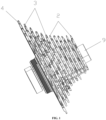
FIG. 1 is a schematic diagram of an overall structure of the present disclosure; -
FIG. 2 is a schematic diagram of a partial structure of the present disclosure; -
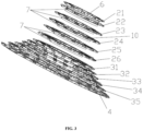
FIG. 3 is a schematic exploded diagram of the present disclosure; and -
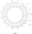
FIG. 4 is a schematic structural diagram of an internal spline of the present disclosure. - In the drawings: 1: cassette body; 2: split freewheel set; 21: first freewheel plate; 22: second freewheel plate; 23: third freewheel plate; 24: fourth freewheel plate; 25: fifth freewheel plate; 26: sixth freewheel plate; 3: integrated freewheel set; 31: seventh freewheel plate; 32: eighth freewheel plate; 33: ninth freewheel plate; 34: tenth freewheel plate; 35: eleventh freewheel plate; 4: bottom freewheel plate; 5: external spline; 6: internal spline; 61: internal spline groove; 62: protrusion; 63: flat curve; 7: boss; 8: rivet; 9: hub; and 10: groove.
- The technical solutions in the embodiments of the present disclosure will be described clearly and completely below with reference to the drawings in the embodiments of the present disclosure. Obviously, the embodiments described herein are only part of the embodiments of the present disclosure, not all the embodiments. Based on the embodiments in the present disclosure, all other embodiments obtained by those of ordinary skill in the art without creative work shall fall within the protection scope of the present disclosure.
- Referring to
FIG. 1 to FIG. 4 , the present disclosure provides a novel bicycle freewheel, including a cassette body 1. The cassette body 1 is mounted on a hub 9. An external spline 5 is arranged on an outer surface of the cassette body 1. Asplit freewheel set 2 is mounted at a front portion of the cassette body 1. An integratedfreewheel set 3 is mounted at a middle portion of the cassette body 1. Abottom freewheel plate 4 is mounted at a rear portion of the cassette body 1. Fin angle imitation streamlines are arranged on upper surfaces of each freewheel plate of thesplit freewheel set 2, the integrated freewheel set 3, and thebottom freewheel plate 4. By using the fin angle imitation streamlines, stress on the freewheel plates is improved, and the speed change efficiency of the freewheel is higher. The splitfreewheel set 2 includes afirst freewheel plate 21, a second freewheel plate 22, athird freewheel plate 23, afourth freewheel plate 24, afifth freewheel plate 25, and asixth freewheel plate 26 from front to back in sequence. An internal spline 6 matched with the external spline 5 is arranged on an inner surface of each freewheel plate of thesplit freewheel set 2. The internal splines 6 of thefirst freewheel plate 21, the second freewheel plate 22, thethird freewheel plate 23, thefourth freewheel plate 24, and thefifth freewheel plate 25 include a plurality ofinternal spline grooves 61 uniformly arranged in a circumferential direction. Aprotrusion 62 is arranged at a middle section of one of theinternal spline grooves 61. One end of theinternal spline groove 61 is aflat curve 63. One end of each split freewheel plate of the split freewheel set 2 connected to the next freewheel plate is provided with a boss 7 extending backwards.Grooves 10 matched with the bosses are respectively formed in surfaces of the second freewheel plate 22, thethird freewheel plate 23, thefourth freewheel plate 24, thefifth freewheel plate 25, and thesixth freewheel plate 26. Thegrooves 10 may limit the bosses 7, so that each freewheel plate can be stably connected, and a reasonable clearance can be reserved between wheel teeth. The integratedfreewheel set 3 is arranged at a rear portion of thesixth freewheel plate 26. The integratedfreewheel set 3 includes aseventh freewheel plate 31, aneighth freewheel plate 32, aninth freewheel plate 33, atenth freewheel plate 34, and aneleventh freewheel plate 35 from front to back in sequence. The seventh to eleventh freewheel plates are integrally formed. Similarly, an internal spline 6 matched with the external spline 5 is arranged on an inner surface of the integratedfreewheel set 3, so that the freewheel is stably connected to the cassette body 1. The integratedfreewheel set 3 is fixed to thebottom freewheel plate 4 through a rivet 8. Preferably, the internal splines and the external spline of the present disclosure are of wide-tooth-groove structures, thereby enlarging a contact area between the freewheel and the cassette body and reducing damage to the cassette body. During use of the present disclosure, thebottom freewheel plate 4 at the rear portion of the freewheel is fixed to the integratedfreewheel set 3 at the middle portion through the rivet 8; and thefirst freewheel plate 21, the second freewheel plate 22, thethird freewheel plate 23, thefourth freewheel plate 24, thefifth freewheel plate 25, and thesixth freewheel plate 26 are assembled together, so that a user can directly use a tool to fix the assembled freewheel to the cassette body of the wheel set. Compared with an existing product, the novel bicycle freewheel has a larger contact area between the freewheel and the cassette body and can reduce damage to a hub and a ratchet. Due to the multi-tooth hierarchical design of the front section of the freewheel, the novel bicycle freewheel is easy to assemble and disassemble and facilitates independent replacement, and the use cost can be reduced. - It should be noted that in this context, relational terms such as first and second are used merely to distinguish one entity or operation from another entity or operation, instead of necessarily requiring or implying that these entities or operations have any of these actual relationships or orders. Furthermore, terms "include", "including" or any other variants are meant to cover non-exclusive inclusions, so that a process, method, object or device that includes a series of elements not only includes those elements, but also includes other elements which are not definitely listed, or further includes inherent elements of this process, method, object or device. Without more restrictions, elements defined by a sentence "includes a/an ..." do not exclude that the process, method, object or device that includes the elements still includes other identical elements.
- Although the embodiments of the present disclosure have been shown and described, it will be understood by those of ordinary skill in the art that various changes, modifications, substitutions, and transformations can be made to these embodiments without departing from the principle and spirit of the present disclosure. The scope of the present disclosure is defined by the attached claims and their equivalents.
Claims (9)
- A novel bicycle freewheel, comprising a cassette body, and further comprising a split freewheel set arranged at a front portion of the freewheel, an integrated freewheel set arranged at a middle portion of the freewheel, and a bottom freewheel plate arranged at a rear portion of the freewheel, wherein the split freewheel set is composed of a plurality of freewheel plates with single teeth; the freewheel plates are respectively mounted at a front portion of the cassette body; the entire integrated freewheel set is mounted at a middle portion of the cassette body; and the integrated freewheel set is riveted to the bottom freewheel plate.
- The novel bicycle freewheel according to claim 1, wherein an external spline is arranged on an outer surface of the cassette body; and internal splines matched with the spline are arranged on an inner surface of each freewheel plate of the split freewheel set and an inner surface of the integrated freewheel set.
- The novel bicycle freewheel according to claim 2, wherein the internal splines and the external spline are of wide-tooth-groove structures.
- The novel bicycle freewheel according to claim 1, wherein the split freewheel set comprises a first freewheel plate, a second freewheel plate, a third freewheel plate, a fourth freewheel plate, a fifth freewheel plate, and a sixth freewheel plate from front to back in sequence; the integrated freewheel set is arranged at a rear portion of the sixth freewheel plate; and the first freewheel plate and the second freewheel plate, the second freewheel plate and the third freewheel plate, the third freewheel plate and the fourth freewheel plate, the fourth freewheel plate and the fifth freewheel plate, and the fifth freewheel plate and the sixth freewheel plate are annularly clamped.
- The novel bicycle freewheel according to claim 4, wherein one end of each split freewheel plate connected to the next freewheel plate is provided with a boss extending backwards.
- The novel bicycle freewheel according to claim 5, wherein grooves matched with the bosses are respectively formed in surfaces of the second freewheel plate, the third freewheel plate, the fourth freewheel plate, the fifth freewheel plate, and the sixth freewheel plate.
- The novel bicycle freewheel according to claim 1, wherein the integrated freewheel set comprises a seventh freewheel plate, an eighth freewheel plate, a ninth freewheel plate, a tenth freewheel plate, and an eleventh freewheel plate from front to back in sequence; the seventh to eleventh freewheel plates are integrally formed; and the integrated freewheel set is fixed to the bottom freewheel plate through a rivet.
- The novel bicycle freewheel according to claim 1, wherein fin angle imitation streamlines are arranged on upper surfaces of each freewheel plate of the split freewheel set, the integrated freewheel set, and the bottom freewheel plate.
- The novel bicycle freewheel according to claim 4, wherein the internal splines of the first freewheel plate, the second freewheel plate, the third freewheel plate, the fourth freewheel plate, and the fifth freewheel plate comprise a plurality of internal spline grooves uniformly arranged in a circumferential direction; a protrusion is arranged at a middle section of one of the internal spline grooves; and one end of the internal spline groove is a flat curve.
Applications Claiming Priority (1)
| Application Number | Priority Date | Filing Date | Title |
|---|---|---|---|
| CN202222915577.8U CN218408333U (en) | 2022-11-02 | 2022-11-02 | Novel bicycle flywheel |
Publications (2)
| Publication Number | Publication Date |
|---|---|
| EP4365070A2 true EP4365070A2 (en) | 2024-05-08 |
| EP4365070A3 EP4365070A3 (en) | 2024-07-31 |
Family
ID=85007514
Family Applications (1)
| Application Number | Title | Priority Date | Filing Date |
|---|---|---|---|
| EP23177450.6A Withdrawn EP4365070A3 (en) | 2022-11-02 | 2023-06-06 | Riveted modular bicycle sprocket |
Country Status (5)
| Country | Link |
|---|---|
| US (1) | US20240141958A1 (en) |
| EP (1) | EP4365070A3 (en) |
| CN (1) | CN218408333U (en) |
| CH (1) | CH720192A2 (en) |
| GB (1) | GB2624060A (en) |
Family Cites Families (16)
| Publication number | Priority date | Publication date | Assignee | Title |
|---|---|---|---|---|
| DE4401272C1 (en) * | 1994-01-18 | 1995-03-16 | Fichtel & Sachs Ag | Multiple sprocket for bicycle derailleurs |
| US6382381B1 (en) * | 2000-09-06 | 2002-05-07 | Shimano Inc. | Bicycle hub assembly |
| US20080004143A1 (en) * | 2006-06-16 | 2008-01-03 | Shimano Inc. | Bicycle sprocket assembly |
| JP2008189254A (en) * | 2007-02-07 | 2008-08-21 | Shimano Inc | Rear sprocket assembly for bicycle, and sprocket |
| ITMI20071658A1 (en) * | 2007-08-09 | 2009-02-10 | Campagnolo Srl | PINION MODULE FOR A BICYCLE AND SPROCKET PACK INCLUDING THIS MODULE |
| US7871347B2 (en) * | 2007-10-11 | 2011-01-18 | Shimano Inc. | Bicycle rear sprocket assembly |
| DE102008010904B4 (en) * | 2008-02-23 | 2021-10-21 | Sram Deutschland Gmbh | Multiple chain sprocket for a bicycle |
| DE102010053597B4 (en) * | 2010-12-07 | 2021-12-02 | Sram Deutschland Gmbh | Multiple sprocket assembly for a bicycle |
| US8696503B2 (en) * | 2011-03-01 | 2014-04-15 | Shimano Inc. | Bicycle sprocket assembly |
| US8956254B2 (en) * | 2011-08-04 | 2015-02-17 | Shimano Inc. | Bicycle sprocket assembly |
| CN105015695A (en) * | 2015-07-22 | 2015-11-04 | 郑英 | Light large-torque high-rigidity variable speed bicycle chain wheel assembly structure |
| US10093388B2 (en) * | 2016-06-28 | 2018-10-09 | Shimano Inc. | Bicycle rear sprocket assembly |
| US10112681B2 (en) * | 2016-07-21 | 2018-10-30 | Shimano Inc. | Bicycle sprocket supporting member and bicycle sprocket assembly |
| CN111542471A (en) * | 2017-08-21 | 2020-08-14 | 劲锋铁马股份有限公司 | Bicycle cone pulley with clamping connection |
| DE102017008074A1 (en) * | 2017-08-28 | 2019-02-28 | Sram Deutschland Gmbh | Sprocket carrier and multiple sprocket assembly |
| DE102021000448A1 (en) * | 2020-02-22 | 2021-08-26 | Sram Deutschland Gmbh | Bicycle rear wheel sprocket arrangement and a modular system for generating bicycle rear wheel sprocket arrangements |
-
2022
- 2022-11-02 CN CN202222915577.8U patent/CN218408333U/en active Active
-
2023
- 2023-06-06 EP EP23177450.6A patent/EP4365070A3/en not_active Withdrawn
- 2023-06-12 GB GB2308734.9A patent/GB2624060A/en active Pending
- 2023-06-13 US US18/209,065 patent/US20240141958A1/en not_active Abandoned
- 2023-06-19 CH CH000654/2023A patent/CH720192A2/en unknown
Also Published As
| Publication number | Publication date |
|---|---|
| US20240141958A1 (en) | 2024-05-02 |
| CH720192A2 (en) | 2024-05-15 |
| CN218408333U (en) | 2023-01-31 |
| EP4365070A3 (en) | 2024-07-31 |
| GB2624060A (en) | 2024-05-08 |
| GB202308734D0 (en) | 2023-07-26 |
Similar Documents
| Publication | Publication Date | Title |
|---|---|---|
| CN203740093U (en) | Bicycle rear sprocket set | |
| US20240141958A1 (en) | Novel Bicycle Freewheel | |
| EP4321420A1 (en) | Motor shaft anti-rotation structure and motor shaft securing method | |
| US20060043786A1 (en) | Rear hub assembly for a bicycle | |
| WO2021023216A1 (en) | Stator assembly and manufacturing method therefor, and hydraulic torque converter comprising stator assembly | |
| US20110168513A1 (en) | Freewheel structure | |
| US7704009B2 (en) | Axial spacer for a rotational assembly | |
| CN2414236Y (en) | Axial-flow fan | |
| CN2937633Y (en) | One-way clutch | |
| CN217945434U (en) | Bicycle chain wheel and connecting and fixing structure thereof | |
| CN210769523U (en) | Fan blade structure of outer rotor fan | |
| CN216608819U (en) | Impact wrench shaft sleeve installation mechanism | |
| CN211424755U (en) | End cover sideboard structure of concurrent flow evaporator | |
| CN216464314U (en) | Pneumatic tool and gas circuit system thereof | |
| CN220622546U (en) | A flywheel set for bicycles and bicycle | |
| CN223953195U (en) | Multistage speed reduction synchronous pulley | |
| CN218670525U (en) | Novel center frame for gear box | |
| US8535001B2 (en) | Fastening of the rotor of a centrifugal pump | |
| CN215861229U (en) | Torsional spring type anti-backlash nut | |
| CN223331084U (en) | Detachable chain wheel | |
| CN210416206U (en) | Integrated steel plate stretching electric hub shell | |
| CN220234364U (en) | Motor frame with special structure | |
| CN218477375U (en) | End face flat-pushing ratchet wheel for bicycle | |
| CN209852519U (en) | Tooth disc with detachable and replaceable tooth parts | |
| CN221003253U (en) | Riveted fan impeller |
Legal Events
| Date | Code | Title | Description |
|---|---|---|---|
| PUAI | Public reference made under article 153(3) epc to a published international application that has entered the european phase |
Free format text: ORIGINAL CODE: 0009012 |
|
| STAA | Information on the status of an ep patent application or granted ep patent |
Free format text: STATUS: THE APPLICATION HAS BEEN PUBLISHED |
|
| AK | Designated contracting states |
Kind code of ref document: A2 Designated state(s): AL AT BE BG CH CY CZ DE DK EE ES FI FR GB GR HR HU IE IS IT LI LT LU LV MC ME MK MT NL NO PL PT RO RS SE SI SK SM TR |
|
| PUAL | Search report despatched |
Free format text: ORIGINAL CODE: 0009013 |
|
| AK | Designated contracting states |
Kind code of ref document: A3 Designated state(s): AL AT BE BG CH CY CZ DE DK EE ES FI FR GB GR HR HU IE IS IT LI LT LU LV MC ME MK MT NL NO PL PT RO RS SE SI SK SM TR |
|
| RIC1 | Information provided on ipc code assigned before grant |
Ipc: B60B 27/04 20060101ALI20240621BHEP Ipc: F16H 55/30 20060101ALI20240621BHEP Ipc: B62M 9/10 20060101AFI20240621BHEP |
|
| STAA | Information on the status of an ep patent application or granted ep patent |
Free format text: STATUS: THE APPLICATION IS DEEMED TO BE WITHDRAWN |
|
| 18D | Application deemed to be withdrawn |
Effective date: 20250201 |