EP4365067A1 - Straddled vehicle - Google Patents
Straddled vehicle Download PDFInfo
- Publication number
- EP4365067A1 EP4365067A1 EP23208031.7A EP23208031A EP4365067A1 EP 4365067 A1 EP4365067 A1 EP 4365067A1 EP 23208031 A EP23208031 A EP 23208031A EP 4365067 A1 EP4365067 A1 EP 4365067A1
- Authority
- EP
- European Patent Office
- Prior art keywords
- base
- case
- wall
- seal
- straddled vehicle
- Prior art date
- Legal status (The legal status is an assumption and is not a legal conclusion. Google has not performed a legal analysis and makes no representation as to the accuracy of the status listed.)
- Pending
Links
Images



Classifications
-
- B—PERFORMING OPERATIONS; TRANSPORTING
- B62—LAND VEHICLES FOR TRAVELLING OTHERWISE THAN ON RAILS
- B62J—CYCLE SADDLES OR SEATS; AUXILIARY DEVICES OR ACCESSORIES SPECIALLY ADAPTED TO CYCLES AND NOT OTHERWISE PROVIDED FOR, e.g. ARTICLE CARRIERS OR CYCLE PROTECTORS
- B62J43/00—Arrangements of batteries
- B62J43/20—Arrangements of batteries characterised by the mounting
- B62J43/28—Arrangements of batteries characterised by the mounting hidden within the cycle frame
-
- B—PERFORMING OPERATIONS; TRANSPORTING
- B62—LAND VEHICLES FOR TRAVELLING OTHERWISE THAN ON RAILS
- B62K—CYCLES; CYCLE FRAMES; CYCLE STEERING DEVICES; RIDER-OPERATED TERMINAL CONTROLS SPECIALLY ADAPTED FOR CYCLES; CYCLE AXLE SUSPENSIONS; CYCLE SIDECARS, FORECARS, OR THE LIKE
- B62K11/00—Motorcycles, engine-assisted cycles or motor scooters with one or two wheels
- B62K11/02—Frames
- B62K11/04—Frames characterised by the engine being between front and rear wheels
-
- B—PERFORMING OPERATIONS; TRANSPORTING
- B62—LAND VEHICLES FOR TRAVELLING OTHERWISE THAN ON RAILS
- B62J—CYCLE SADDLES OR SEATS; AUXILIARY DEVICES OR ACCESSORIES SPECIALLY ADAPTED TO CYCLES AND NOT OTHERWISE PROVIDED FOR, e.g. ARTICLE CARRIERS OR CYCLE PROTECTORS
- B62J41/00—Arrangements of radiators, coolant hoses or pipes on cycles
-
- B—PERFORMING OPERATIONS; TRANSPORTING
- B60—VEHICLES IN GENERAL
- B60K—ARRANGEMENT OR MOUNTING OF PROPULSION UNITS OR OF TRANSMISSIONS IN VEHICLES; ARRANGEMENT OR MOUNTING OF PLURAL DIVERSE PRIME-MOVERS IN VEHICLES; AUXILIARY DRIVES FOR VEHICLES; INSTRUMENTATION OR DASHBOARDS FOR VEHICLES; ARRANGEMENTS IN CONNECTION WITH COOLING, AIR INTAKE, GAS EXHAUST OR FUEL SUPPLY OF PROPULSION UNITS IN VEHICLES
- B60K1/00—Arrangement or mounting of electrical propulsion units
- B60K1/04—Arrangement or mounting of electrical propulsion units of the electric storage means for propulsion
-
- B—PERFORMING OPERATIONS; TRANSPORTING
- B60—VEHICLES IN GENERAL
- B60L—PROPULSION OF ELECTRICALLY-PROPELLED VEHICLES; SUPPLYING ELECTRIC POWER FOR AUXILIARY EQUIPMENT OF ELECTRICALLY-PROPELLED VEHICLES; ELECTRODYNAMIC BRAKE SYSTEMS FOR VEHICLES IN GENERAL; MAGNETIC SUSPENSION OR LEVITATION FOR VEHICLES; MONITORING OPERATING VARIABLES OF ELECTRICALLY-PROPELLED VEHICLES; ELECTRIC SAFETY DEVICES FOR ELECTRICALLY-PROPELLED VEHICLES
- B60L50/00—Electric propulsion with power supplied within the vehicle
- B60L50/50—Electric propulsion with power supplied within the vehicle using propulsion power supplied by batteries or fuel cells
- B60L50/60—Electric propulsion with power supplied within the vehicle using propulsion power supplied by batteries or fuel cells using power supplied by batteries
- B60L50/66—Arrangements of batteries
-
- B—PERFORMING OPERATIONS; TRANSPORTING
- B62—LAND VEHICLES FOR TRAVELLING OTHERWISE THAN ON RAILS
- B62J—CYCLE SADDLES OR SEATS; AUXILIARY DEVICES OR ACCESSORIES SPECIALLY ADAPTED TO CYCLES AND NOT OTHERWISE PROVIDED FOR, e.g. ARTICLE CARRIERS OR CYCLE PROTECTORS
- B62J43/00—Arrangements of batteries
- B62J43/10—Arrangements of batteries for propulsion
- B62J43/16—Arrangements of batteries for propulsion on motorcycles or the like
-
- B—PERFORMING OPERATIONS; TRANSPORTING
- B62—LAND VEHICLES FOR TRAVELLING OTHERWISE THAN ON RAILS
- B62J—CYCLE SADDLES OR SEATS; AUXILIARY DEVICES OR ACCESSORIES SPECIALLY ADAPTED TO CYCLES AND NOT OTHERWISE PROVIDED FOR, e.g. ARTICLE CARRIERS OR CYCLE PROTECTORS
- B62J43/00—Arrangements of batteries
- B62J43/20—Arrangements of batteries characterised by the mounting
-
- B—PERFORMING OPERATIONS; TRANSPORTING
- B62—LAND VEHICLES FOR TRAVELLING OTHERWISE THAN ON RAILS
- B62J—CYCLE SADDLES OR SEATS; AUXILIARY DEVICES OR ACCESSORIES SPECIALLY ADAPTED TO CYCLES AND NOT OTHERWISE PROVIDED FOR, e.g. ARTICLE CARRIERS OR CYCLE PROTECTORS
- B62J9/00—Containers specially adapted for cycles, e.g. panniers or saddle bags
- B62J9/10—Containers specially adapted for cycles, e.g. panniers or saddle bags integrated with the cycle
- B62J9/18—Containers specially adapted for cycles, e.g. panniers or saddle bags integrated with the cycle in a dummy fuel tank
-
- H—ELECTRICITY
- H01—ELECTRIC ELEMENTS
- H01M—PROCESSES OR MEANS, e.g. BATTERIES, FOR THE DIRECT CONVERSION OF CHEMICAL ENERGY INTO ELECTRICAL ENERGY
- H01M50/00—Constructional details or processes of manufacture of the non-active parts of electrochemical cells other than fuel cells, e.g. hybrid cells
- H01M50/20—Mountings; Secondary casings or frames; Racks, modules or packs; Suspension devices; Shock absorbers; Transport or carrying devices; Holders
- H01M50/233—Mountings; Secondary casings or frames; Racks, modules or packs; Suspension devices; Shock absorbers; Transport or carrying devices; Holders characterised by physical properties of casings or racks, e.g. dimensions
- H01M50/24—Mountings; Secondary casings or frames; Racks, modules or packs; Suspension devices; Shock absorbers; Transport or carrying devices; Holders characterised by physical properties of casings or racks, e.g. dimensions adapted for protecting batteries from their environment, e.g. from corrosion
-
- H—ELECTRICITY
- H01—ELECTRIC ELEMENTS
- H01M—PROCESSES OR MEANS, e.g. BATTERIES, FOR THE DIRECT CONVERSION OF CHEMICAL ENERGY INTO ELECTRICAL ENERGY
- H01M50/00—Constructional details or processes of manufacture of the non-active parts of electrochemical cells other than fuel cells, e.g. hybrid cells
- H01M50/20—Mountings; Secondary casings or frames; Racks, modules or packs; Suspension devices; Shock absorbers; Transport or carrying devices; Holders
- H01M50/249—Mountings; Secondary casings or frames; Racks, modules or packs; Suspension devices; Shock absorbers; Transport or carrying devices; Holders specially adapted for aircraft or vehicles, e.g. cars or trains
-
- B—PERFORMING OPERATIONS; TRANSPORTING
- B60—VEHICLES IN GENERAL
- B60K—ARRANGEMENT OR MOUNTING OF PROPULSION UNITS OR OF TRANSMISSIONS IN VEHICLES; ARRANGEMENT OR MOUNTING OF PLURAL DIVERSE PRIME-MOVERS IN VEHICLES; AUXILIARY DRIVES FOR VEHICLES; INSTRUMENTATION OR DASHBOARDS FOR VEHICLES; ARRANGEMENTS IN CONNECTION WITH COOLING, AIR INTAKE, GAS EXHAUST OR FUEL SUPPLY OF PROPULSION UNITS IN VEHICLES
- B60K1/00—Arrangement or mounting of electrical propulsion units
-
- B—PERFORMING OPERATIONS; TRANSPORTING
- B60—VEHICLES IN GENERAL
- B60K—ARRANGEMENT OR MOUNTING OF PROPULSION UNITS OR OF TRANSMISSIONS IN VEHICLES; ARRANGEMENT OR MOUNTING OF PLURAL DIVERSE PRIME-MOVERS IN VEHICLES; AUXILIARY DRIVES FOR VEHICLES; INSTRUMENTATION OR DASHBOARDS FOR VEHICLES; ARRANGEMENTS IN CONNECTION WITH COOLING, AIR INTAKE, GAS EXHAUST OR FUEL SUPPLY OF PROPULSION UNITS IN VEHICLES
- B60K1/00—Arrangement or mounting of electrical propulsion units
- B60K1/04—Arrangement or mounting of electrical propulsion units of the electric storage means for propulsion
- B60K2001/0455—Removal or replacement of the energy storages
- B60K2001/0466—Removal or replacement of the energy storages from above
-
- B—PERFORMING OPERATIONS; TRANSPORTING
- B60—VEHICLES IN GENERAL
- B60L—PROPULSION OF ELECTRICALLY-PROPELLED VEHICLES; SUPPLYING ELECTRIC POWER FOR AUXILIARY EQUIPMENT OF ELECTRICALLY-PROPELLED VEHICLES; ELECTRODYNAMIC BRAKE SYSTEMS FOR VEHICLES IN GENERAL; MAGNETIC SUSPENSION OR LEVITATION FOR VEHICLES; MONITORING OPERATING VARIABLES OF ELECTRICALLY-PROPELLED VEHICLES; ELECTRIC SAFETY DEVICES FOR ELECTRICALLY-PROPELLED VEHICLES
- B60L2200/00—Type of vehicles
- B60L2200/12—Bikes
-
- B—PERFORMING OPERATIONS; TRANSPORTING
- B60—VEHICLES IN GENERAL
- B60Y—INDEXING SCHEME RELATING TO ASPECTS CROSS-CUTTING VEHICLE TECHNOLOGY
- B60Y2200/00—Type of vehicle
- B60Y2200/10—Road Vehicles
- B60Y2200/12—Motorcycles, Trikes; Quads; Scooters
-
- B—PERFORMING OPERATIONS; TRANSPORTING
- B60—VEHICLES IN GENERAL
- B60Y—INDEXING SCHEME RELATING TO ASPECTS CROSS-CUTTING VEHICLE TECHNOLOGY
- B60Y2410/00—Constructional features of vehicle sub-units
- B60Y2410/10—Housings
-
- B—PERFORMING OPERATIONS; TRANSPORTING
- B62—LAND VEHICLES FOR TRAVELLING OTHERWISE THAN ON RAILS
- B62K—CYCLES; CYCLE FRAMES; CYCLE STEERING DEVICES; RIDER-OPERATED TERMINAL CONTROLS SPECIALLY ADAPTED FOR CYCLES; CYCLE AXLE SUSPENSIONS; CYCLE SIDECARS, FORECARS, OR THE LIKE
- B62K2204/00—Adaptations for driving cycles by electric motor
Definitions
- the present invention relates to a straddled vehicle including a structure that prevents water from entering an accommodating space of a case of the straddled vehicle.
- the straddled vehicle includes a battery case.
- the battery case includes a case cover that can open and close an opening portion of the battery case such that the battery is put in or taken out from the battery case.
- An object of the present invention is to provide a straddled vehicle that can prevent water from entering an opening portion.
- a straddled vehicle of the present invention includes: a base including a base opening through which an accommodating space is open to an upper side and an opposing portion located around the base opening; an outer lid that opens and closes the base opening; a projection that is located at one of the outer lid and the base, is located outside the base opening, and projects in an upper-lower direction toward the other of the outer lid and the base; and an outer wall that is located at the outer lid or the base, faces the projection from an outside, and is located between the outer lid and the opposing portion in the upper-lower direction.
- the opposing portion is inclined relative to a horizontal direction.
- the outer wall includes a drain passage that is located at a position lower than an upper end of the opposing portion and extends from an inside of the outer wall to an outside of the outer wall.
- both of the outer wall and the projection prevents water from entering the base opening. Moreover, water may flow over the outer wall and enter a space between the outer wall and the projection. Even in this case, the water flows downward by the inclination of the opposing portion and flows to the outside through the drain passage of the outer wall. Thus, the water is prevented from entering the accommodating space.
- a straddled vehicle according to an embodiment will be described with reference to the attached drawings.
- a front-rear direction, a left-right direction (lateral direction), and an upper-lower direction are directions when viewed from a rider who is seated on the straddled vehicle.
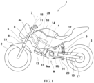
- FIG. 1 is a side view of a straddled vehicle (vehicle) 1 according to the present embodiment. As shown in FIG. 1 , in the present embodiment, the straddled vehicle 1 is a motorcycle.
- the straddled vehicle 1 includes a front wheel 2, a rear wheel 3, and a vehicle body frame 4.
- the vehicle body frame 4 is supported by the front wheel 2 and the rear wheel 3.
- the straddled vehicle 1 includes a front fork 5 that connects the front wheel 2 and the vehicle body frame 4 and is located between the front wheel 2 and the vehicle body frame 4.
- the front fork 5 is coupled to a bracket 8 which is located under a steering shaft 7 so as to be spaced apart from the steering shaft 7 in the upper-lower direction.
- the front fork 5 extends in an upper, rear, and diagonal direction.
- the front fork 5 includes a front suspension 6.
- the front fork 5 can expand and contract in its longitudinal direction when a spring in the front suspension 6 elastically deforms.
- the front fork 5 expands and contracts in the longitudinal direction to ease shock transmitted to the vehicle body frame 4.
- the steering shaft 7 connected to the bracket 8 is supported by a head pipe 4a, which is part of the vehicle body frame 4, so as to be angularly displaceable.
- the straddled vehicle 1 includes a rear suspension 9 that connects the rear wheel 3 to a rear portion of the vehicle body frame 4.
- a swing arm 10 supporting the rear wheel 3 and extending in the front-rear direction is supported by the vehicle body frame 4 so as to be angularly displaceable.
- the straddled vehicle 1 includes an electric motor M as a driving source that generates force to be transmitted to the wheel.
- the electric motor M is mounted on the vehicle body frame 4 so as to be located between the front wheel 2 and the rear wheel 3.
- the electric motor M serves as a prime mover that generates rotational driving force to be transmitted to the rear wheel 3.
- the straddled vehicle 1 includes a battery 14 and a case 13 accommodating the battery 14 therein.
- the battery 14 stores electric power to be supplied to electrical components. Moreover, in the present embodiment, the battery 14 supplies the electric power to the electric motor M. Thus, the electric motor M is driven, and the straddled vehicle 1 travels.
- the battery 14 is connected to the electric motor M through an electric wire.
- the case 13 is attached to the vehicle body frame 4.
- the electric motor M includes a motor case Ma and a motor drive shaft Mb projecting from the motor case Ma.
- a sprocket 16 is located at the motor drive shaft Mb so as to rotate together with the motor drive shaft Mb.
- a gear or a pulley may be used as a rotary member.
- a chain 17 is connected to the sprocket 16 located at the motor drive shaft Mb.
- the driving force output by the motor drive shaft Mb is transmitted to the rear wheel 3 through the chain 17.
- a member through which the driving force output by the motor drive shaft Mb is transmitted to the rear wheel 3 is not limited to the chain and may be another power transmitting member, such as a belt.
- an ECU (electronic control unit) 39 is located in front of the case 13.
- the ECU 39 controls the driving of the electric motor M by adjusting the electric power to be supplied from the battery 14 through a BMU (battery management unit) and an inverter to the electric motor M.
- Throttle equipment 18 is operated by the rider and controls the driving of the electric motor M in accordance with the operation of the rider.
- the front fork 5 expands and contracts in the longitudinal direction. Since the front suspension 6 expands and contracts to ease the shock to be transmitted to the vehicle body frame 4, the shock transmitted to the rider can be reduced. Thus, the ride quality for the rider can be improved.
- the straddled vehicle 1 includes a front fender 19 that is connected to the front fork 5 and moves up and down together with the front fork 5 in accordance with the expansion and contraction of the front fork 5.
- the front fender 19 is attached to the front fork 5 so as to project from the front fork 5 in the front-rear direction and cover an upper side of the front wheel 2.
- the straddled vehicle 1 includes a side stand 20.
- the straddled vehicle 1 stops and stands by itself by the side stand 20, the straddled vehicle 1 leans toward a side where the side stand 20 is attached.
- the vehicle body is inclined.
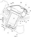
- FIG. 2 is a sectional view taken along a plane extending in the front-rear direction and showing the case 13 and its vicinity when the outer lid 53 is opened, and an inner lid 42 located inside the outer lid 53 and covering an upper side of the battery 14 is detached.
- FIG. 3 is a sectional view taken along a plane extending in the front-rear direction and showing the case 13 and its vicinity when the outer lid 53 is closed, and the inner lid 42 located inside the outer lid 53 and covering the upper side of the battery 14 is attached.
- the case 13 is a case that can accommodate the battery 14.
- the case 13 defines an accommodating space 25 that accommodates the battery 14.
- the case 13 includes the accommodating space 25 that corresponds to two batteries 14a and 14b so as to accommodate the two batteries 14a and 14b.
- the case 13 includes: an inner bottom wall 28 that is inclined downward as it extends rearward; and a peripheral wall 29 that extends upward from the inner bottom wall 28 and surrounds the accommodating space 25.
- the case 13 includes a case opening 21 that opens the accommodating space 25 of the battery 14 to an upper side such that the battery 14 is put in or taken out from the accommodating space 25.
- the case 13 When the case 13 is attached to the straddled vehicle 1, the case 13 is inclined relative to a vertical direction such that the case opening 21 is directed in an upper, rear, and diagonal direction. To be specific, the case 13 is attached to the straddled vehicle 1 so as to be inclined rearward as it extends upward from its lower end.
- the accommodating space 25 of the case 13 is configured such that the area of a section of the accommodating space 25 which is orthogonal to an insertion direction of the battery 14 decreases as the accommodating space 25 extends downward.
- the case 13 is configured such that front and rear inner surfaces of the case 13 form a tapered shape, i.e., approach each other as they extend downward. As the inner surface of the case 13 extends downward, the inner surface of the case 13 extends toward an inner side by an upper portion where a step 22 is located and a lower portion 24 that is located under the upper portion and tapers.
- a bottom portion of the case 13 has a double bottom structure 35.
- the double bottom structure 35 of the bottom portion of the case 13 includes the inner bottom wall 28, an outer bottom wall 48 covering the inner bottom wall 28 from below, and a peripheral wall 30 that connects the outer bottom wall 48 to the inner bottom wall 28.
- the case 13 is attached to the straddled vehicle 1 so as to be inclined. Therefore, with the case 13 attached to the straddled vehicle 1, the inner bottom wall 28 is inclined downward as it extends rearward.
- Connectors 31 projecting toward an inside of the accommodating space 25 are located at the inner bottom wall 28 of the case 13. In the present embodiment, the two connectors 31 are located so as to correspond to the first battery 14a and the second battery 14b which are mounted on the case 13.
- Wires connected to the connectors 31 are located in a lower space 33 between the outer bottom wall 48 and the inner bottom wall 28 in the double bottom structure 35 of the case 13.
- the lower space 33 is located outside the accommodating space 25 and is adjacent to the accommodating space 25 across the inner bottom wall 28.
- the wires connected to the connectors 31 extend inside the lower space 33, extend to an outside from a rear portion of the lower space 33, and extend rearward.
- the wires extend from the connectors 31, penetrate the inside of the inner bottom wall 28 of the case 13, extend toward the lower space 33, extend rearward in the lower space 33, and extend to the outside of the case 13.
- the outer bottom wall 48 and the peripheral wall 30 are configured separately from the inner bottom wall 28.
- the outer bottom wall 48 and the peripheral wall 30 constitute a lid body 36 as one piece.
- the lower space 33 is defined by the inner bottom wall 28 and the lid body 36 so as to be located between the inner bottom wall 28 and the lid body 36.
- the battery 14 includes an output terminal 32 connected to the connectors 31 when the battery 14 is accommodated in the accommodating space 25 of the case 13.
- the first battery 14a includes an output terminal 44
- the second battery 14b includes an output terminal 45. These output terminals 44 and 45 are collectively called the output terminal 32.
- the connectors 31 of the case 13 and the output terminal 32 of the battery 14 are connected to each other, and therefore, the electric power from the battery 14 can be supplied through the wires to the electric motor M and the like.
- the case 13 accommodates the two batteries 14a and 14b. Therefore, the case 13 includes a partition 41 that projects from the inner bottom wall 28 of the case 13 to the inside of the accommodating space 25 so as to divide a space for storing the two batteries 14a and 14b lined up in a vehicle width direction in the straddled vehicle 1. Spaces for the two batteries 14a and 14b are separated from each other by the partition 41, and therefore, the batteries 14a and 14b can be located at appropriate positions.
- the straddled vehicle 1 includes the inner lid 42 located at an upper side of the case 13. As shown in FIG. 3 , the inner lid 42 that closes the case opening 21 is attached to the case 13. After the battery 14 is stored in the case 13, the inner lid 42 covers the upper side of the battery 14 and protects the battery 14. In the present embodiment, the inner lid 42 is fixed to the case 13 by screwing.
- the case 13 is attached to the straddled vehicle 1 so as to be located in front of and adjacent to the electric motor M.
- the case 13 is located between the front fork 5 and the electric motor M in the front-rear direction of the straddled vehicle 1.
- the case 13 is located so as to be inclined.
- the case 13 is located between the front wheel 2 and the rear wheel 3, and therefore, the accommodating space 25 is located between the front wheel 2 and the rear wheel 3. Moreover, in the present embodiment, the case 13 is located between the head pipe 4a and the seat 12, and therefore, the accommodating space 25 is located between the head pipe 4a and the seat 12.
- the case 13 is attached to the vehicle body frame 4 so as to be inclined rearward as it extends upward from its lower end. Therefore, there is a space which is located in front of the case 13 and at which things can be put.
- the ECU 39 is located at this space located in front of the case 13. Therefore, spaces in the straddled vehicle 1 can be efficiently utilized.
- the ECU 39 since the ECU 39 is located in front of the case 13, the ECU 39 can be located at the space that directly receives traveling wind.
- the ECU 39 can be efficiently cooled by the traveling wind.
- the ECU 39 easily generates heat by the traveling of the straddled vehicle 1. Therefore, by cooling the ECU 39 by the traveling wind, the temperature of the ECU can be maintained at an appropriate temperature even during the traveling of the straddled vehicle 1.
- the straddled vehicle 1 includes a base 52 located at the upper side of the case 13.
- the base 52 is located in front of the seat 12 and above the inner lid 42.
- the base 52 is attached to the case 13 from above so as to surround the case opening 21 and defines part of the accommodating space 25.
- a space inside the base 52 and a space inside the case 13 are collectively called the accommodating space 25.
- the base 52 includes an opposing portion 60 located around a base opening 52a through which the accommodating space 25 inside the base 52 is open to the upper side.
- the opposing portion 60 is located outside the base opening 52a and has a closed loop shape that surrounds the base opening 52a.
- the opposing portion 60 includes a surface that is adjacently located at a radially outer side of the base opening 52a and faces upward. Moreover, the opposing portion 60 includes a below-described opposing surface that is opposed to the outer lid 53 from below when the outer lid 53 is closed.
- the base 52 includes a non-opposing surface 52c that is located outside the opposing surface and is exposed from the outer lid 53.
- the non-opposing surface 52c has a closed loop shape that surrounds the opposing surface.
- the non-opposing surface 52c is part of an appearance surface constituting the appearance of the straddled vehicle 1.
- the battery 14 When the battery 14 is accommodated in the case 13 mounted on the straddled vehicle 1, the battery 14 is protected by the case 13, the inner lid 42, and the outer lid 53, and the upper side of the battery 14 is doubly covered with the inner lid 42 and the outer lid 53.
- the base 52 is attached to a flange 67 located at an upper end of the peripheral wall 29 of the case 13. Moreover, in the present embodiment, the base 52 is located in front of the seat 12 and partially embedded in a cover 50 of the straddled vehicle 1, and a portion of the base 52 which projects from the cover 50 constitutes an outer surface of the straddled vehicle 1.
- the straddled vehicle 1 includes the outer lid 53 that can open and close the base opening 52a.
- the outer lid 53 is attached to an outer lid attaching portion 51 located at the base 52.
- the case 13 is located between the legs of the rider who straddles the seat 12.
- An upper end 53a of the outer lid 53 projects upward beyond the seat 12.
- the outer lid attaching portion 51 of the base 52 includes a hinge portion 54 by which the outer lid 53 is turnably connected to the base 52.
- the outer lid 53 turns about the hinge portion 54 to open and close the base opening 52a.
- the outer lid 53 is configured as a design part that is exposed to the outside and constitutes the appearance of the vehicle body of the straddled vehicle 1. In other words, the straddled vehicle 1 does not include a member that covers the outer lid 53 from the outside.
- FIG. 4 is a sectional perspective view which is taken along a plane extending in the front-rear direction and orthogonal to a horizontal plane and shows the base 52 and the case 13 with the outer lid 53 closed.
- the straddled vehicle 1 includes a projection that prevents water from entering the accommodating space 25.
- the projection is located at the outer lid 53, is opposed to the opposing portion 60 of the base 52, and projects downward from the outer lid 53.
- the projection is located outside the base opening 52a. In other words, the projection is located around the base opening 52a so as to surround the outside of the base opening 52a.
- the projection is realized by a seal 61 that seals a gap between the outer lid 53 and the opposing portion 60 with the outer lid 53 closed.
- the seal 61 is attached to an outer edge of the outer lid 53 so as to face the base opening 52a.
- the seal 61 is attached to the outer lid 53 so as to project from the outer lid 53 toward the opposing portion 60.
- the seal 61 is attached to the outer lid 53 such that with the outer lid 53 closed, the seal 61 is located on the opposing portion 60.
- the seal 61 is made of a material having flexibility and is deformable. Since the seal 61 deforms to seal the gap between the opposing portion 60 and the outer lid 53, the gap between the opposing portion 60 and the outer lid 53 in the upper-lower direction can be sealed.
- a base space 40 that is part of the accommodating space 25 is located inside the base 52.
- the base space 40 is used as a space through which the battery 14 passes when the battery 14 is put in or taken out from the case 13.
- the base space 40 is located above the case 13 in an insertion direction in which the battery 14 is inserted into the case 13.
- the accommodating space 25 of the case 13 is accessible through the base space 40, and the battery 14 can be accommodated in the accommodating space 25.
- the base space 40 includes a space located at an upper side of the inner lid 42.
- the outer lid 53 covering the base space 40 is opened.
- the inner lid 42 located above the case 13 is detached.
- the accommodating space 25 of the case 13 is accessible from the outside.
- the battery 14 passes through the base space 40 of the base 52 and the case opening 21 of the case 13 and is accommodated in the accommodating space 25 of the case 13.
- the inner lid 42 is attached to an upper side of the case 13, and the base space 40 is closed by the outer lid 53.
- accommodating the battery 14 in the case 13 is completed.
- the opposing portion 60 is located at a radially innermost position of the base 52 so as to face the base opening 52a of the base 52.
- the seal 61 is attached to the outer lid 53 such that with the outer lid 53 closed, the seal 61 contacts the opposing portion 60.
- the base 52 includes an outer wall 62 located outside the seal 61.
- the outer wall 62 is located adjacent to a contact portion 60g of the opposing portion 60 which contacts the seal 61. With the outer lid 53 closed, the outer wall 62 is located outside the seal 61 and between the outer lid 53 and the opposing portion 60 in the upper-lower direction. In other words, the outer wall 62 is located in a space surrounded by the outer lid 53 and the opposing portion 60.
- the outer wall 62 projects upward beyond the contact portion 60g of the opposing portion 60 which contacts the seal 61.
- the outer wall 62 projects upward beyond a lower end of the outer lid 53 which is located outside the outer wall 62.
- the outer lid 53 includes a lower position 53d covering the outer wall 62 from the outside. Since a labyrinth structure is formed by the outer lid 53 and the outer wall 62 as above, the entering of the water is easily prevented. Moreover, a gap in the upper-lower direction exists between the outer wall 62 and the outer lid 53. Thus, a decrease in pressing force of the seal 61 since the outer wall 62 contacts the outer lid 53 can be prevented.
- the outer lid 53 includes an upper plate 53b and a lower plate 53c.
- the upper plate 53b is located at an upper side of the lower plate 53c and closes the base opening 52a.
- the lower plate 53c supports the seal 61.
- an end portion of an outer edge of the lower plate 53c is sandwiched by the seal 61.
- the seal 61 is attached to the lower plate 53c in such a manner that the end portion of the outer edge of the lower plate 53c is sandwiched by the seal 61. Since the upper plate 53b closes the base opening 52a, water is prevented from entering the accommodating space 25.
- the seal 61 since the seal 61 is attached to the lower plate 53c, the seal 61 seals the gap between the lower plate 53c and the opposing portion 60, and this prevents water from entering the accommodating space 25.
- FIG. 5 is a perspective view showing the base 52 of the straddled vehicle 1 and its vicinity when viewed obliquely from above.
- FIG. 6 is a partially enlarged side view showing the base 52 and the outer lid 53 in the straddled vehicle 1 of FIG. 5 .
- FIG. 6 is a diagram showing the base 52 and the outer lid 53 in the straddled vehicle 1 when viewed from a direction that is orthogonal to the vertical direction and the front-rear direction.
- the outer shape of the outer lid 53 is shown by a one-dot chain line.
- the opposing portion 60 and the seal 61 are located so as to surround the base opening.
- the opposing portion 60 includes a portion 60a extending in the vehicle width direction and a portion 60b extending in the front-rear direction
- the seal 61 includes a portion 61a extending in the vehicle width direction and a portion 61b extending in the front-rear direction.
- the portion 60a extending in the vehicle width direction in the opposing portion 60 includes a front portion 60c extending in the vehicle width direction and a rear portion 60d extending in the vehicle width direction.
- the portion 61a extending in the vehicle width direction in the seal 61 includes a front portion 61c extending in the vehicle width direction and a rear portion 61d extending in the vehicle width direction.
- the seal 61 attached to the outer lid 53 is placed on the opposing portion 60.
- the front portion 60c of the portion 60a extending in the vehicle width direction linearly extends substantially in the vehicle width direction.
- the rear portion 60d of the portion 60a extending in the vehicle width direction is the highest at the middle in the vehicle width direction, and is inclined downward therefrom as it extends outward in the vehicle width direction.
- the portion 60b extending in the vehicle front-rear direction in the opposing portion 60 is inclined downward as it extends rearward from its front end.
- the opposing portion 60 is inclined relative to a horizontal direction.
- An intermediate portion of the portion extending in the front-rear direction in the opposing portion 60 includes a lowest portion.
- the lowest portion is located at a rear side of the middle portion in the front-rear direction in the opposing portion 60.
- the opposing portion 60 is inclined upward as it extends rearward from the lowest portion, and the opposing portion is continuous with the portion extending in the vehicle width direction.
- the opposing portion 60 is substantially line-symmetrical with respect to a center line L1 in the vehicle width direction.
- a guide portion 60h is located at an inner side of the contact portion 60g of the opposing portion 60 which contacts the seal 61.
- the guide portion 60h restricts the movement of the seal 61 toward the inner side.
- the guide portion 60h is located at the entire inner periphery of the contact portion 60g of the opposing portion 60 so as to surround the inside of the contact portion 60g.
- the guide portion 60h does not include a cutout.
- the case 13 is attached to the vehicle body frame 4 such that the case 13 is inclined rearward as it extends upward from the lower end. Therefore, the base 52 attached onto the case 13 is inclined rearward as it extends upward from the lower end. Moreover, in the present embodiment, the opposing portion 60 of the base 52 is inclined. Since the base 52 is located so as to be inclined, the inclination of the opposing portion 60 of the base 52 is easily realized.
- the outer wall 62 is located at a radially outer side of the seal 61 surrounding the base opening 52a.
- the outer wall 62 includes: a portion extending in the front-rear direction; a front portion extending in the vehicle width direction; and a rear portion extending in the vehicle width direction.
- the front portion extending in the vehicle width direction is located in front of the portion 61c of the seal 61.
- the rear portion extending in the vehicle width direction is located behind the portion 61d of the seal 61.
- the outer wall 62 has a shape that is partially cut out. Specifically, a cutout portion 63 (discharge passage) of the outer wall 62 is located between the portion extending in the vehicle front-rear direction and the rear portion extending in the vehicle width direction. At the cutout portion 63 of the outer wall 62, the outer wall 62 does not cover the seal 61. To be specific, since the outer wall 62 includes the cutout portion 63, the outer wall 62 includes a drain passage 64 extending from the inside of the outer wall 62 to the outside. The cutout portion 63 is formed by cutting out the outer wall 62 such that water having moved to the outside of the opposing portion 60 in the vehicle width direction flows to the outside of the vehicle 1.
- the height of this portion in the upper-lower direction from the opposing portion 60 decreases as this portion extends from the front side to the rear side.
- the height of the outer wall 62 in the upper-lower direction becomes the smallest at the cutout portion 63.
- the outer wall 62 is the same in height as the opposing portion 60.
- FIG. 7 is a sectional view taken along line VII-VII of FIG. 6 .
- FIG. 8 is a sectional view taken along line VIII-VIII of FIG. 6 .
- FIG. 9 is a sectional view taken along line IX-IX of FIG. 6 .
- the outer wall 62 covers the outside of the portion 61b of the seal 61.
- the outer wall 62 is cut out at the cutout portion 63, water having entered a space between the seal 61 and the outer wall 62 is prevented from being blocked by the outer wall 62.
- the water having entered the space between the seal 61 and the outer wall 62 flows to the outside of the vehicle 1.
- a gap exists at least between the base 52 and the outer lid 53 in the vehicle width direction.
- the portion 61b of the seal 61 is not covered with the outer wall 62 at the cutout portion 63 and is exposed to the outside of the vehicle 1 entirely in the upper-lower direction.
- the seal 61 surrounding the base opening 52a includes: a covered portion 61e including a radially outer portion that is covered with the outer wall 62 with the outer lid 53 removed; and an exposed portion 61f including a radially outer portion that is exposed to the outside with the outer lid 53 removed. With the outer lid 53 removed, at least the exposed portion 61f of the seal 61 is located at a position of the opposing portion 60 which is the lowest in the upper-lower direction.
- the cutout portion 63 of the outer wall 62 is located at a lowest position of the opposing portion 60 and a lowest position of the seal 61.
- the portion 60b of the opposing portion 60 and the portion 61b of the seal 61 are inclined downward as they extend rearward, and the cutout portion 63 of the outer wall 62 is located at a position corresponding to a front-rear direction rearmost portion of the portion 60b of the opposing portion 60 and a front-rear direction rearmost portion of the portion 61b of the seal 61. Therefore, the outer wall 62 exposes the exposed portion 61f of the seal 61 to the outside of the vehicle 1 entirely in the upper-lower direction at the lowest position of the opposing portion 60.
- the contact portion 60g of the opposing portion 60 is formed by a smooth flat surface or curved surface which is inclined downward from its front end in the front-rear direction to the cutout portion 63.
- the opposing portion 60 can guide in the front-rear direction the water having entered the space between the seal 61 and the outer wall 62.
- the straddled vehicle 1 includes the side stand 20 by which the vehicle can stand by itself in a state of being inclined toward a first side in the vehicle width direction (see FIG. 1 ).
- the side stand 20 contacts a ground surface at a side where the side stand 20 exists.
- the straddled vehicle 1 is inclined toward the side where the side stand 20 exists in the vehicle width direction.
- the exposed portion 61f of the seal 61 is located at both sides in the vehicle width direction, i.e., the exposed portion 61f of the seal 61 includes two portions.
- the exposed portion 61f includes: a side stand-side exposed portion located at the side where the side stand 20 exists; and an opposite-side exposed portion located at a side where the side stand 20 does not exist. Since the exposed portion 61f is located at both sides in the vehicle width direction, the water is discharged through the side stand-side exposed portion and the opposite-side exposed portion, and therefore, the water in the space between the seal 61 and the outer wall 62 can be efficiently discharged. Thus, the water can be surely prevented from entering the accommodating space 25.
- the straddled vehicle 1 is inclined toward the side stand 20, and therefore, the side stand-side exposed portion is located lower than the opposite-side exposed portion in the upper-lower direction.
- the lowest position of the opposing portion 60 is located at a side (first side) of the base opening 52a in the vehicle width direction toward which the straddled vehicle 1 is inclined when the straddled vehicle 1 stands by itself by the side stand 20.
- the seal 61 has an elongated shape that is longer than the outer periphery of the base opening 52a.
- the elongated seal 61 extends along the base opening 52a and is located at a radially inner side of the outer wall 62.
- the seal 61 partially overlaps itself in the radial direction of the base opening 52a.
- a portion where the seal 61 overlaps itself in the radial direction is referred to as an overlapping portion 61g.
- the overlapping portion 61g of the seal 61 is located at the side of the base opening 52a in the vehicle width direction toward which the straddled vehicle 1 is inclined when the straddled vehicle 1 stands by itself by the side stand 20. Therefore, when the straddled vehicle 1 stands by itself by the side stand 20, the overlapping portion 61g of the seal 61 is located at the side at which the side stand 20 exists and toward which the straddled vehicle 1 is inclined. Thus, in the seal 61, the overlapping portion 61g is located lower in the upper-lower direction than a side where the overlapping portion 61g does not exist.
- the seal 61 since the seal 61 has an elongated shape as described above, the seal 61 includes two longitudinal end portions. Moreover, as described above, the portions of the opposing portion 60 and the seal 61 which extend in the front-rear direction of the straddled vehicle 1 are inclined downward in the upper-lower direction as they extend from the front side to the rear side in the front-rear direction.
- the seal 61 includes a first end portion (first longitudinal end portion) 61h and a second end portion (second longitudinal end portion) 61i.
- the first end portion 61h is located at the front side, and the seal 61 extends rearward therefrom.
- the second end portion 61i is located at the rear side, and the seal 61 extends forward therefrom.
- the second end portion 61i is an end portion opposite to the first end portion 61h.
- a portion 61n of the seal 61 extends from the first end portion 61h to the rear side of the vehicle 1, and a portion 61p of the seal 61 extends from the second end portion 61i to the front side of the vehicle 1.
- the portion 61n and the portion 61p overlap each other in the radial direction at the overlapping portion 61g.
- the first end portion 61h of the seal 61 is located at a radially inner side of the second end portion 61i of the seal 61.
- the second end portion 61i of the seal 61 is located at a rear side of the first end portion 61h of the seal 61 in the front-rear direction.
- the second end portion 61i of the seal 61 is located lower than the first end portion 61h of the seal 61 in the upper-lower direction.
- the second end portion 61i located at a radially outer side of the first end portion 61h is located lower than the first end portion 61h located at a radially inner side of the second end portion 61i.
- the portion 61n extending from the first end portion 61h of the seal 61 to the rear side of the vehicle 1 and the portion 61p extending from the second end portion 61i of the seal 61 to the front side of the vehicle 1 overlap each other in the radial direction at the overlapping portion 61g.
- the volume of the seal 61 is large at the portion where the first end portion 61h and the second end portion 61i overlap each other in the radial direction. Therefore, at the portion where the first end portion 61h and the second end portion 61i overlap each other in the radial direction, a large space for accommodating the seal 61 is required.
- the opposing portion 60 includes a space 60k in which the seal 61 is located, and a radial width of the space 60k is made large.
- the radial width of the space 60k of the opposing portion 60 is made larger than the radial width of the other space of the opposing portion 60, and therefore, the seal 61 is surely held by the opposing portion 60.
- FIG. 10 is a perspective view showing a connection portion 65 between the vehicle body frame 4 and the case 13 and its vicinity when the base 52 is detached from the case 13.
- FIG. 11 is a sectional perspective view showing an internal structure of the case 13.
- the case 13 includes a main body 66 and the flange 67.
- the main body 66 defines the accommodating space 25.
- the flange 67 is located around the case opening 21 and projects outward in the radial direction from the main body 66.
- the main body 66 of the case 13 includes the peripheral wall 29 and the inner bottom wall 28 which define the accommodating space 25 that accommodates the battery 14.
- the flange 67 is a plate portion located at an upper side of the peripheral wall 29.
- the flange 67 is located around the case opening 21 at the upper side of the peripheral wall 29 and projects outward beyond the peripheral wall 29.
- a mount portion 68 is located in the vicinity of a front-rear direction end portion of the flange 67 of the case 13. Moreover, the mount portion 68 includes a hole 69.
- a support bracket 70 is located at a position of the vehicle body frame 4 which is opposed to the mount portion 68.
- a plate member 72 extending inward in the vehicle width direction from a pipe 73 constituting the vehicle body frame 4 is located at the vehicle body frame 4, and the support bracket 70 is attached onto the plate member 72.
- the support bracket 70 is formed by bending a plate-shaped member.
- a protrusion 71 projecting upward is located on an upper surface of the support bracket 70.
- the protrusion 71 of the support bracket 70 attached to the vehicle body frame 4 is inserted into the hole 69 of the flange 67 of the case 13 from below.
- a bushing 74 is attached to the protrusion 71.
- the case 13 is connected to the vehicle body frame 4.
- the base 52 When the case 13 is connected to the vehicle body frame 4, the base 52 is attached to an upper side of the case 13. As shown in FIG. 4 , the base 52 includes an eaves portion 75 which is located at a front position in the front-rear direction of the straddled vehicle 1, projects downward, and covers the protrusion 71 and the mount portion 68 from above.
- the base 52 includes a base main body 52b and the eaves portion 75 including a projecting portion 75a.
- the base main body 52b is located at an upper side of the case 13 and defines part of the accommodating space 25, and the projecting portion 75a projects downward from the base main body 52b.
- a lower end 75b of the projecting portion 75a of the eaves portion 75 is located lower than an upper surface of the mount portion 68.
- the projecting portion 75a of the eaves portion 75 extends at the base 52 over the entirety in the vehicle width direction. Therefore, the projecting portion 75a closes a joint between the base 52 and the case 13 over the entirety in the vehicle width
- a bottom wall 56 of the case 13 includes a drain hole.
- the bottom wall 56 includes the inner bottom wall 28, the outer bottom wall 48, and the peripheral wall 30 that connects the outer bottom wall 48 to the inner bottom wall 28.
- the bottom wall 56 includes a bottom wall drain hole 76. Since the bottom wall 56 includes the bottom wall drain hole 76, water having entered the accommodating space 25 can be discharged from the accommodating space 25.
- the inner bottom wall 28 facing the accommodating space 25 includes inner bottom wall drain holes 77 penetrating the inner bottom wall 28.
- the inner bottom wall drain holes 77 are located at the spaces in which the two batteries 14a and 14b are respectively accommodated.
- the lid body 36 including the outer bottom wall 48 and the peripheral wall 30 includes a lid body drain hole 78 penetrating the lid body 36.
- the lid body drain hole 78 is located at a rear portion of the peripheral wall 30 of the lid body 36.
- the lid body drain hole 78 is located at a position close to a lower end 30a of the peripheral wall 30.
- the inner bottom wall 28 includes the inner bottom wall drain holes 77 penetrating the inner bottom wall 28, the water having entered the accommodating space 25 of the case 13 is guided to the lower space 33. Moreover, since the lid body 36 includes the lid body drain hole 78 penetrating the peripheral wall 30, the water having entered the lower space 33 is discharged to the outside.
- the inner bottom wall drain hole 77 is located at a position that is low at least when the vehicle body is inclined by using the side stand 20.
- the inner bottom wall 28 includes an inner bottom wall drain hole 86 through which the water having entered the accommodating space 25 is directly discharged to the outside without being guided to the lower space 33.
- a lower partition wall 79 is located inside the lower space 33.
- the lower partition wall 79 projects upward from the outer bottom wall 48 and extends at the lid body 36 over the entirety in the vehicle width direction.
- a slight gap between the lower partition wall 79 and the inner bottom wall 28 in the upper-lower direction exists above the lower partition wall 79, but the lower partition wall 79 exists in the lower space 33 substantially entirely in the upper-lower direction.
- an upper partition wall 80 is located inside the lower space 33. The upper partition wall 80 projects downward from the inner bottom wall 28 and extends at the lid body 36 over the entirety in the vehicle width direction.
- a gap between the upper partition wall 80 and the outer bottom wall 48 in the upper-lower direction is relatively large, and a length of the upper partition wall 80 in the upper-lower direction is shorter than a length of the lower partition wall 79 in the upper-lower direction.
- the lower partition wall 79 is located in front of the upper partition wall 80 in the front-rear direction.
- the lower partition wall 79 includes a partition wall drain hole 81 penetrating the lower partition wall 79 in the front-rear direction.
- the partition wall drain hole 81 is located at a position of the lower partition wall 79 which is close to the outer bottom wall 48.
- the partition wall drain hole 81 is located at a position close to a lower end of the lower partition wall 79.
- the partition wall drain hole 81 is also included in the bottom wall drain hole 76.
- an upper portion of the peripheral wall 29 of the case 13 includes peripheral wall drain holes 82 penetrating the peripheral wall 29. Therefore, when water enters the accommodating space 25 through a gap between the base 52 and the case 13, the water flows along the peripheral wall 29 by gravity toward the peripheral wall drain holes 82, flows through the peripheral wall drain holes 82, and is discharged to the outside of the accommodating space 25 of the case 13.
- the peripheral wall drain holes 82 are located at two portions of the case 13 which are located at a front position and a rear position in the front-rear direction.
- the peripheral wall 29 includes a front peripheral wall 29b located at a front side and a rear peripheral wall 29c located at a rear side.
- the front peripheral wall 29b includes: a front peripheral wall main body portion 29d extending upward from the inner bottom wall 28; a front portion 29e that is bend forward in the front-rear direction from the front peripheral wall main body portion 29d and extends upward as it extends forward; a bent portion 29f at which the front peripheral wall 29b is bent; and a partition plate 29g extending upward from the bent portion 29f. Therefore, even when water flows through a joint between the base 52 and the case 13, the partition plate 29g prevents the water from entering a battery accommodating position of the accommodating space 25.
- the water is once stored in a front space 88 surrounded by the base 52, the front portion 29e, and the partition plate 29g.
- the water having entered the front space 88 of the accommodating space 25 flows downward along a wall surface of the front portion 29e and is discharged to the outside through the peripheral wall drain hole 82 of the front peripheral wall 29b.
- the water is prevented from entering the battery accommodating position of the accommodating space 25.
- the rear peripheral wall 29c includes: a rear peripheral wall main body portion 29h extending upward from the inner bottom wall 28; a rear portion 29i that is bent rearward in the front-rear direction from the rear peripheral wall main body portion 29h and extends upward as it extends rearward; a bent portion 29k at which the rear peripheral wall 29c is bent; and a partition plate 29m extending upward from the bent portion 29k. Therefore, even when water flows through the joint between the base 52 and the case 13, the partition plate 29m prevents the water from entering the battery accommodating position of the accommodating space 25. The water is once stored in a rear space 89 surrounded by the base 52, the rear portion 29i, and the partition plate 29m.
- the water having entered the rear space 89 of the accommodating space 25 flows downward along a wall surface of the rear portion 29i and is discharged to the outside through the peripheral wall drain hole 82 of the rear peripheral wall 29c.
- the water is prevented from entering the battery accommodating position of the accommodating space 25.
- the inner lid 42 is located at the case 13 so as to close the case opening 21 of the case 13. Therefore, even when water flows through the base opening 52a, the inner lid 42 prevents the water from entering the battery accommodating position of the accommodating space 25.
- the base 52 includes a base drain hole 90 penetrating the base 52. Therefore, even when water enters the base opening 52a, the water can be discharged to the outside through the base drain hole 90. Thus, the water can be surely prevented from entering the battery accommodating position of the accommodating space 25.
- the seal 61 faces the base opening 52a, is attached to the outer lid 53, and projects toward the opposing portion 60 of the base 52, and the outer wall 62 is located outside the seal 61 and between the outer lid 53 and the opposing portion 60 in the upper-lower direction. Therefore, by both of the seal 61 and the outer wall 62, the water is prevented from entering the accommodating space 25. Even when the water flows over the outer wall 62 and enters the inside of the outer wall 62, the seal 61 prevents the water from entering the accommodating space 25. Moreover, the outer wall 62 exposes the seal 61 or the opposing portion 60 to the outside of the vehicle 1 at the lowest position of the opposing portion 60.
- the opposing surface 60e of the opposing portion 60 which is opposed to the outer lid 53 is inclined relative to the horizontal direction.
- a portion of the opposing surface 60e which is located at a lateral side of the base opening 52a is inclined downward as it extends rearward.
- the outer wall 62 does not exist or is cut out at the exposed portion 61f. Therefore, when the water reaches the exposed portion 61f, the water having entered the space between the outer wall 62 and the seal 61 is discharged from the opposing portion 60 to the outside. Thus, the water is prevented from entering the opposing portion 60.
- the cutout portion 63 of the outer wall 62 serves as a discharge passage through which the water in the space 85 is discharged to the outside and which extends from the inside of the outer wall 62 to the outside.
- the seal 61 has an elongated shape.
- the seal 61 is longer than the outer periphery of the base opening 52a.
- the seal 61 partially overlaps itself in the radial direction of the base opening 52a.
- the water can be prevented from entering the accommodating space 25 from the joint of the seal 61 through the base opening 52a.
- the opposing portion 60 is inclined downward as it extends from the front side to the rear side in the front-rear direction.
- the portion 61n of the seal 61 which extends rearward from the first longitudinal end portion 61h and the portion 61p of the seal 61 which extends forward from the second longitudinal end portion 61i overlap each other in the radial direction.
- the second longitudinal end portion 61i located at a radially outer side is located lower than the first longitudinal end portion 61h located at a radially inner side.
- a gap between the portion 61n of the seal 61 which extends rearward from the first longitudinal end portion 61h and the portion 61p of the seal 61 which extends forward from the second longitudinal end portion 61i extends rearward and downward.
- the water is discharged from the outer lid 53 and the base 52 to the outside through the gap between the portion 61n of the seal 61 which extends rearward from the first longitudinal end portion 61h and the portion 61p of the seal 61 which extends forward from the second longitudinal end portion 61i.
- the water having flowed over the outer wall 62 at the overlapping portion 61g of the seal 61 is prevented from entering the accommodating space 25.
- the gap between the portion 61n of the seal 61 which extends rearward from the first longitudinal end portion 61h and the portion 61p of the seal 61 which extends forward from the second longitudinal end portion 61i extends rearward and downward, the water is prevented from entering the accommodating space 25 through the gap during traveling.
- the overlapping portion 61g is located at a position higher than the lowest position of the opposing portion 60. In other words, the overlapping portion 61g is located at a position different from a portion where the outer wall 62 exposes the seal 61 or the opposing portion 60. Therefore, rain water is prevented from reaching the overlapping portion 61g through a portion where the outer wall 62 does not exist or is cut out.
- the lowest position of the opposing portion 60 at which the seal 61 is exposed is located at one side of the base opening 52a in the vehicle width direction at which the side stand 20 exists. Therefore, when the straddled vehicle 1 stands by itself by using the side stand 20, the water having entered the space between the seal 61 and the outer wall 62 can be discharged to the outside of the vehicle 1 through the exposed portion 61k located at the side at which the side stand 20 exists. Thus, the drainage property can be improved.
- the overlapping portion 61g of the seal 61 is located at one side of the base opening 52a in the vehicle width direction which is lower than the other side since the straddled vehicle 1 is inclined. Therefore, when water enters the space between the seal 61 and the outer wall 62, the water is discharged to the outside through the gap between the portion 61n extending rearward from the first longitudinal end portion 61h and the portion 61p extending forward from the second longitudinal end portion 61i at the overlapping portion 61g while the straddled vehicle 1 is in a stop state. Thus, the drainage property can be improved.
- the inner lid 42 that can open and close the case opening 21 is included, the water is more surely prevented from entering the accommodating space 25.
- the peripheral wall 29 includes the peripheral wall drain holes 82. Therefore, even when the water enters the accommodating space 25, the water is discharged to the outside. Thus, the water is prevented from entering an electrical connection portion where the output terminal 32 of the battery 14 and the connectors 31 of the case 13 are connected to each other.
- the base 52 since the base 52 includes the eaves portion 75 covering the flange 67 of the case 13 from above, the eaves portion 75 can close the joint between the base 52 and the case 13. Therefore, the water flowing along the base 52 is prevented from entering the accommodating space 25, and the water is prevented from entering the accommodating space 25 through the joint between the base 52 and the case 13. Thus, the waterproof property of the case 13 can be improved.
- the bottom wall 56 includes the bottom wall drain hole 76 through which the water having entered the accommodating space 25 is discharged from the accommodating space 25. Therefore, even when water enters the accommodating space 25, the water can be discharged through the bottom wall drain hole 76 to the outside of the case 13.
- the lower partition wall 79 projecting upward from the outer bottom wall 48 and the upper partition wall 80 projecting downward from the inner bottom wall 28 are located inside the lower space 33. Therefore, water is prevented from entering a front side of the lower space 33 by the lower partition wall 79 and the upper partition wall 80.
- the case 13 includes the connectors 31, and the lower space 33 is located so as to be adjacent to the connectors 31. Therefore, the wires extending from the connectors 31 are located inside the lower space 33.
- the lower partition wall 79 and the upper partition wall 80 are located behind the wires. Therefore, water is prevented from entering the front side of the lower space 33, and the wires are prevented from contacting the water.
- the lower partition wall 79 includes the partition wall drain hole 81 located close to the outer bottom wall 48, and the case 13 and the lid body 36 are inclined downward as they extend rearward. Therefore, when water enters the lower space 33, the water flows toward the outer bottom wall 48 at the lower side by gravity. When the water reaches the outer bottom wall 48, the water flows rearward along the inclined outer bottom wall 48. Since the partition wall drain hole 81 is located at a lower portion of the lower partition wall 79, the water flowing along the outer bottom wall 48 flows rearward through the partition wall drain hole 81 and is discharged through the lid body drain hole 78 to the outside of the lid body 36. Therefore, when water enters the lower space 33, the water can be discharged from the lower space 33 through the partition wall drain hole 81.
- the wires from the connectors 31 are located on a lower surface of the inner bottom wall 28, i.e., at an upper portion of the lower space 33. Furthermore, when water enters the lower space 33, the water flows rearward along the outer bottom wall 48. Therefore, even when water enters the lower space 33, the water flows through a space under the wires. Thus, the water is prevented from contacting the wires and can be discharged to the outside of the lower space 33. Therefore, the case 13 that can protect the wires is realized.
- the accommodating space 25 accommodates the battery 14 that supplies electric power to the electric motor M that drives the driving wheel of the vehicle. Therefore, water is prevented from contacting the battery 14 and is prevented from contacting the output terminal 32 of the battery 14.
- the present embodiment also assumes a case where the vehicle body of the straddled vehicle 1 is cleaned by high pressure water. Even when the vehicle body is cleaned by high pressure water, the water is prevented from entering the battery accommodating position by the above-described water entry preventing structure. Moreover, even when a small amount of high pressure water enters the battery accommodating position, the water can be discharged through the bottom wall drain hole 76 to the outside of the case 13. Thus, rain water is prevented from being accumulated in the case 13.
- the above embodiment has described a case where the seal 61 and the outer wall 62 are located at the base 52.
- the seal 61 and the outer wall 62 may be located at the outer lid 53.
- the seal 61 may be located at one of the base 52 and the outer lid 53, and the outer wall 62 may be located at the other of the base 52 and the outer lid 53.
- Each of the seal 61 and the outer wall 62 may be located at any of the outer lid 53 and the base 52 as long as each of the seal 61 and the outer wall 62 is located at the outer lid 53 or the base 52, the space between the outer lid 53 and the base 52 is closed, and water is prevented from entering the base opening 52a.
- the above embodiment has described a case where the vehicle is an electric straddled vehicle.
- the vehicle may be a hybrid vehicle driven by an electric motor and an internal combustion engine.
- the vehicle may be of a type that is driven only by an internal combustion engine.
- the vehicle may be of any type as long as the vehicle includes the outer lid, the case, and the base, and prevents water from entering the gap between the outer lid and the base when the outer lid is closed.
- the above embodiment has described a case where the projection that is attached to the outer lid 53, faces the base opening 52a, and projects toward the base 52 is the seal 61.
- the projection may be located between the outer lid 53 and the opposing portion 60 in the upper-lower direction and close part of the space between the outer lid 53 and the opposing portion 60. As long as the projection closes part of the space between the outer lid 53 and the opposing portion 60, the projection may close the entire space between the outer lid 53 and the opposing portion 60 or may partially close the space between the outer lid 53 and the opposing portion 60. Moreover, the projection does not have to be deformable.
- the projection may an inner wall located at a radially inner side of the outer wall 62. The projection is located at the outer lid but may be located at the opposing portion.
- the opposing portion 60 is inclined downward as it extends rearward from its front portion.
- the above embodiment is not limited to this.
- the opposing portion 60 may be inclined downward as it extends forward from its rear portion.
- the opposing portion 60 may be inclined downward as it extends outward in the vehicle width direction from its vehicle width direction inner portion.
- the above embodiment has described a case where when the outer lid 53 is detached, the radially outer portion of the exposed portion 61f of the seal 61 is exposed at the lowest position of the opposing portion 60.
- the above embodiment is not limited to this.
- the opposing portion 60 with which the seal 61 contacts may be exposed to the outside.
- the opposing portion 60 and the seal 61 may not be exposed with the outer lid 53 attached.
- the above embodiment has described a case where the exposed portion 61f is located at both of the left and right sides in the vehicle width direction.
- the exposed portion 61f may be located at only one of the left and right sides in the vehicle width direction. In this case, there may be only the side stand-side exposed portion that is located at the lowest position of the opposing portion 60 since the straddled vehicle 1 is inclined when the straddled vehicle 1 stands by itself by using the side stand 20.
- the exposed portion 61f may include exposed portions located at one side of the straddled vehicle 1 in the vehicle width direction.
- the above embodiment has described a case where the radially outer portion of the exposed portion 61f of the seal 61 is exposed at the lowest position of the opposing portion 60.
- the above embodiment is not limited to this. It is desirable that in consideration of the drainage property, a portion where the opposing portion 60 or the seal 61 is exposed be located at the lowest position of the opposing portion 60 with the straddled vehicle 1 inclined since the straddled vehicle 1 stands by itself by using the side stand 20.
- the exposed portion 61f may be located in a region that is low to some extent in the opposing portion 60.
- the exposed portion 61f may be located at a position that is higher than the lowest position to such an extent that water does not enter the base opening 52a.
- the cutout portion 63 may be located in a region that is low to some extent in the opposing portion 60.
- the cutout portion 63 may be located at a position that is higher than the lowest position to such an extent that water does not enter the base opening 52a.
- the exposed portion 61f may be located at regions located at the lowest positions of the opposing portion 60.
- the exposed portion 61f be located lower than a front-rear direction middle portion of the opposing portion 60.
- the opposing surface 60e of the opposing portion 60 which is opposed to the outer lid 53 is a surface that is horizontal along the vehicle width direction.
- the above embodiment is not limited to this.
- the opposing surface 60e may be inclined.
- the opposing surface 60e is inclined downward as it extends from the inside to the outside in the radial direction, the water having entered the space surrounded by the opposing surface 60e, the seal 61, and the outer wall 62 flows outward in the radial direction along the inclination of the opposing surface 60e, and the water is prevented from flowing inward in the radial direction. Therefore, it is preferable that to prevent the water from entering the base opening 52a, the opposing surface 60e be inclined downward as it extends from the inside to the outside in the radial direction.
- the above embodiment has described a case where the seal 61 is located so as to surround the base opening 52a, and the exposed portion 61f is located so as to face the base opening 52a.
- the exposed portion 61f may be located at a position away from the base opening 52a in the front-rear direction.
- the seal 61 may be located so as to surround the base opening 52a while extending through the position away from the base opening 52a in the front-rear direction, the radially outer portion of the seal 61 may be exposed at the position away from the base opening 52a in the front-rear direction, and the exposed portion 61f may be located at the position away from the base opening 52a in the front-rear direction.
- the cutout portion 63 of the outer wall 62 may be located behind a rear end of the base opening 52a or a rear end of the case opening 21. Since the outer wall 62 is located as above, water is prevented from entering the base opening 52a through the cutout portion 63. Moreover, the cutout portion 63 may be located away from the overlapping portion 61g of the seal 61 in the front-rear direction. Especially, it is preferable that the cutout portion 63 be located away in the rear direction from the overlapping portion 61g of the seal 61 as in the present embodiment.
- the above embodiment has described a case where the base opening 52a is located in front of the seat 12.
- the base opening 52a may be located at another position.
- the base opening 52a may be located behind the seat 12 or may be located right under the seat 12.
- the above embodiment has described a case where the radially outer portion of the seal 61 is exposed at the lowest position of the opposing portion 60.
- the position at which the radially outer portion of the seal 61 is exposed is not limited to the lowest position of the opposing portion 60.
- the position at which the radially outer portion of the seal 61 is exposed may be a position lower than an upper end 60f of the opposing portion 60.
- water having entered a region from the upper end 60f to the exposed portion 61f of the seal 61 is discharged at the exposed portion 61f. Therefore, at the region from the upper end 60f to the exposed portion 61f of the seal 61, the water having entered the inside of the outer wall 62 can be discharged, and the drainage property can be improved.
- the above embodiment has described a waterproof structure that prevents water from entering the accommodating space of the battery case at the joint between the outer lid 53 and the base 52.
- the above embodiment is not limited to this.
- the same structure may be applied to case bodies other than the battery case.
- the structure of the above embodiment is applicable to the joint between the outer lid and the opening in the case.
- the above embodiment has described a case where the case 13 and the base 52 are formed separately.
- the case 13 and the base 52 may be formed integrally.
- the case 13 and the base 52 may be formed by integral molding.
- the above embodiment has described a case where the opposing portion 60 is located around the base opening 52a of the base 52.
- the above embodiment is not limited to this.
- the opposing portion 60 may be located around the case opening 21 of the case 13.
- the above embodiment has described a case where the inner lid 42 that closes the case opening 21 is attached to the upper end of the case 13.
- the above embodiment is not limited to this.
- the inner lid 42 does not have to be located at the upper end of the case 13.
- FIG. 12 is a sectional view taken along a line corresponding to line VIII-VIII of FIG. 6 when a portion of the outer lid 53 which extends outward in the radial direction forms the outer wall 62.
- a portion of the seal 61 which is not the exposed portion 61f and is located at a radially outer side is covered with a portion of the upper plate 53b of the outer lid 53 which extends outward, and a radially outer portion of the upper plate 53b of the outer lid 53 serves as an outer wall that covers the radially outer portion of the seal 61.
- a discharge passage 91 through which water is discharged is located between the upper plate 53b of the outer lid 53 and the opposing portion 60 of the base 52.
- the opposing surface 60e of the opposing portion 60 is inclined downward as it extends outward in the radial direction. Therefore, water having entered the space 85 surrounded by the opposing portion 60, the seal 61, and the outer lid 53 flows outward in the radial direction by its own weight. Thus, the water having reached the discharge passage 91 flows outward in the radial direction by its own weight and is discharged through the discharge passage 91 to the outside.
- the discharge passage 91 is located between the upper plate 53b of the outer lid 53 and the base 52. Therefore, even when water enters the space between the outer lid 53 and the seal 61, the water having entered the space 85 surrounded by the outer lid 53, the seal 61, and the opposing portion 60 is discharged through the discharge passage 91 to the outside. Thus, the upper plate 53b of the outer lid 53 prevents the water from entering the opposing portion 60. In addition, even when water enters the opposing portion 60 through the upper plate 53b of the outer lid 53, the water is discharged to the outside of the vehicle 1 and is prevented from being accumulated in the opposing portion 60. Thus, the water is prevented from entering the case opening 21 through the base opening 52a.
- the opposing surface 60e of the opposing portion 60 is inclined downward as it extends outward in the radial direction.
- the opposing surface 60e does not have to be inclined. Even when the opposing surface 60e is horizontal along the vehicle width direction, the water having entered the space between the outer lid 53 and the seal 61 can be discharged to the outside through the discharge passage 91 located between the upper plate 53b and the base 52. Therefore, as long as the water having entered the space between the outer lid 53 and the seal 61 can be discharged to the outside, the opposing surface 60e may be horizontal along the vehicle width direction without being inclined.
- FIG. 13 is a sectional view showing the outer lid 53, the opposing portion 60, and the seal 61 when the outer lid 53 is located at the outer wall.
- FIG. 13 is a sectional view taken along a line corresponding to line VIII-VIII of FIG. 6 .
- an outer wall 62d is located at the upper plate 53b of the outer lid 53.
- the upper plate 53b covers the outside of the opposing portion 60, and the outer wall 62d extends from a lower wall surface of the upper plate 53b toward the opposing portion 60.
- the outer wall 62d located at the outer lid 53 covers a radially outer side of the seal 61. Therefore, at the portion where the discharge passage 91a does not exist, the outer wall 62d prevents water from flowing inward in the radial direction.
- the discharge passage 91a is located in FIG.
- the discharge passage 91a is located between the outer wall 62d and the opposing portion 60 in the upper-lower direction. Since the discharge passage 91a is located under the outer wall 62d, water having entered the space 85 surrounded by the outer lid 53, the seal 61, and the opposing portion 60 is discharged through the discharge passage 91a to the outside. Therefore, the outer wall 62d prevents the water from entering the opposing portion 60. In addition, even when the water has flowed through the outer wall 62d and entered the space 85 surrounded by the outer lid 53, the seal 61, and the opposing portion 60, the water is discharged to the outside of the vehicle 1 and is prevented from being accumulated in the space 85. Thus, the water is prevented from entering the case opening 21 through the base opening 52a.
- FIG. 14 is a sectional view showing the outer lid 53, the opposing portion 60, and a seal 61m when a connection member 92 extending from the opposing portion 60 toward the outer lid 53 is attached to the opposing portion 60, and the seal 61m is attached to an upper side of the connection member 92.
- FIG. 14 is a sectional view taken along a line corresponding to line VIII-VIII of FIG. 6 .
- the seal 61m is attached to the connection member 92 extending upward from the opposing portion 60 toward the outer lid 53.
- the connection member 92 is attached to the opposing portion 60
- the seal 61m is attached to the opposing portion 60.
- the seal 61m is located at the opposing portion 60 of the base 52 and projects upward.
- the seal 61m may be located outside the base opening 52a.
- the projection 61m is located around the base opening 52a so as to surround the outside of the base opening 52a.
- the seal 61m may be attached to the opposing portion 60.
- the upper plate 53b of the outer lid 53 covers a radially outer side of the seal 61m. Therefore, at the portion where the discharge passage 91b does not exist, the upper plate 53b prevents water from entering the radially inner side.
- the discharge passage 91b is located between the upper plate 53b of the outer lid 53 and the opposing portion 60.
- the discharge passage 91b is located between the upper plate 53b of the outer lid 53 and the opposing portion 60, water having entered the space 85 surrounded by the outer lid 53, the seal 61, and the opposing portion 60 is discharged through the discharge passage 91b to the outside. Therefore, the upper plate 53b of the outer lid 53 prevents the water from entering the opposing portion 60. In addition, even when the water has flowed through the upper plate 53b and entered the space 85, the water is discharged to the outside of the vehicle 1 and is prevented from being accumulated in the space 85. Thus, the water is prevented from entering the case opening 21 through the base opening 52a. In FIG. 14 , the upper plate 53b of the outer lid 53 serves as the outer wall.
- a straddled vehicle including:
- the projection is a seal that seals a gap between the outer lid and the opposing portion in the upper-lower direction.
- the straddled vehicle according to any one of the first to fourth aspects, further including a side stand by which the straddled vehicle stands by itself in a state of being inclined toward a first side in a vehicle width direction, wherein when the straddled vehicle stands by itself by using the side stand, a lowest position of the opposing portion at which the projection is exposed is located at the first side of the base opening in the vehicle width direction.
- the straddled vehicle according to any one of the first to fifth aspects, further including:
- the straddled vehicle according to any one of the first to sixth aspects, further including a case including
- the straddled vehicle according to any one of the first to seventh aspects, further including a case including a bottom wall, wherein the bottom wall includes a bottom wall drain hole through which water having entered the accommodating space is discharged from the accommodating space.
- the straddled vehicle according to any one of the first to eighth aspects, further including:
- the accommodating space accommodates a battery that supplies electric power to an electric motor that drives a driving wheel of the straddled vehicle.
Landscapes
- Engineering & Computer Science (AREA)
- Mechanical Engineering (AREA)
- Chemical & Material Sciences (AREA)
- Transportation (AREA)
- Combustion & Propulsion (AREA)
- General Chemical & Material Sciences (AREA)
- Electrochemistry (AREA)
- Chemical Kinetics & Catalysis (AREA)
- Life Sciences & Earth Sciences (AREA)
- Sustainable Development (AREA)
- Sustainable Energy (AREA)
- Power Engineering (AREA)
- Aviation & Aerospace Engineering (AREA)
- Automatic Cycles, And Cycles In General (AREA)
Abstract
Description
- The present invention relates to a straddled vehicle including a structure that prevents water from entering an accommodating space of a case of the straddled vehicle.
- International Publication No.
2015/068753 discloses an electric straddled vehicle including a driving wheel driven by a motor. The straddled vehicle includes a battery case. The battery case includes a case cover that can open and close an opening portion of the battery case such that the battery is put in or taken out from the battery case. - According to the configuration disclosed in International Publication No.
2015/068753 , since there is the opening portion through which the battery is put in or taken out from the battery case, rain water easily enters the inside of the battery case. - An object of the present invention is to provide a straddled vehicle that can prevent water from entering an opening portion.
- A straddled vehicle of the present invention includes: a base including a base opening through which an accommodating space is open to an upper side and an opposing portion located around the base opening; an outer lid that opens and closes the base opening; a projection that is located at one of the outer lid and the base, is located outside the base opening, and projects in an upper-lower direction toward the other of the outer lid and the base; and an outer wall that is located at the outer lid or the base, faces the projection from an outside, and is located between the outer lid and the opposing portion in the upper-lower direction. The opposing portion is inclined relative to a horizontal direction. The outer wall includes a drain passage that is located at a position lower than an upper end of the opposing portion and extends from an inside of the outer wall to an outside of the outer wall.
- According to the present invention, since the outer wall is located between the outer lid and the opposing portion of the base in the upper-lower direction, both of the outer wall and the projection prevents water from entering the base opening. Moreover, water may flow over the outer wall and enter a space between the outer wall and the projection. Even in this case, the water flows downward by the inclination of the opposing portion and flows to the outside through the drain passage of the outer wall. Thus, the water is prevented from entering the accommodating space.
- The above object, other objects, features, and advantages of the present invention will be made clear by the following detailed explanation of preferred embodiments with reference to the attached drawings.
-
-
FIG. 1 is a side view of a straddled vehicle according to an embodiment. -
FIG. 2 is a sectional view taken along a plane extending in a front-rear direction and showing a case of the straddled vehicle ofFIG. 1 and its vicinity when an outer lid is opened, and an inner lid is detached. -
FIG. 3 is a sectional view taken along a plane extending in the front-rear direction and showing the case of the straddled vehicle ofFIG. 1 and its vicinity when a battery is mounted on the case, the inner lid is attached, and the outer lid is closed. -
FIG. 4 is a sectional view showing the outer lid, a base, and the case at a front side of the straddled vehicle ofFIG. 1 . -
FIG. 5 is a perspective view showing the base and its vicinity when the outer lid is detached from the straddled vehicle ofFIG. 1 . -
FIG. 6 is a side view showing the base, the outer lid, and their vicinities in the straddled vehicle ofFIG. 1 . -
FIG. 7 is a sectional view taken along line VII-VII ofFIG. 6 . -
FIG. 8 is a sectional view taken along line VIII-VIII ofFIG. 6 . -
FIG. 9 is a sectional view taken along line IX-IX ofFIG. 6 . -
FIG. 10 is a perspective view showing a connection portion between a vehicle body frame and the case and its vicinity when the base is detached from the case in the straddled vehicle ofFIG. 1 . -
FIG. 11 is a sectional perspective view showing an inside of the case in the straddled vehicle ofFIG. 1 . -
FIG. 12 is a sectional view showing the straddled vehicle according to a modified example and taken along a line corresponding to line VIII-VIII ofFIG. 6 . -
FIG. 13 is a sectional view showing the straddled vehicle of another modified example and taken along a line corresponding to line VIII-VIII ofFIG. 6 . -
FIG. 14 is a sectional view showing the straddled vehicle of yet another modified example and taken along a line corresponding to line VIII-VIII ofFIG. 6 . - Hereinafter, a straddled vehicle according to an embodiment will be described with reference to the attached drawings. In the present specification, a front-rear direction, a left-right direction (lateral direction), and an upper-lower direction are directions when viewed from a rider who is seated on the straddled vehicle.
-
FIG. 1 is a side view of a straddled vehicle (vehicle) 1 according to the present embodiment. As shown inFIG. 1 , in the present embodiment, the straddledvehicle 1 is a motorcycle. - The straddled
vehicle 1 includes afront wheel 2, arear wheel 3, and avehicle body frame 4. Thevehicle body frame 4 is supported by thefront wheel 2 and therear wheel 3. The straddledvehicle 1 includes afront fork 5 that connects thefront wheel 2 and thevehicle body frame 4 and is located between thefront wheel 2 and thevehicle body frame 4. Thefront fork 5 is coupled to abracket 8 which is located under asteering shaft 7 so as to be spaced apart from thesteering shaft 7 in the upper-lower direction. Thefront fork 5 extends in an upper, rear, and diagonal direction. Thefront fork 5 includes afront suspension 6. Thefront fork 5 can expand and contract in its longitudinal direction when a spring in thefront suspension 6 elastically deforms. Thefront fork 5 expands and contracts in the longitudinal direction to ease shock transmitted to thevehicle body frame 4. Thesteering shaft 7 connected to thebracket 8 is supported by ahead pipe 4a, which is part of thevehicle body frame 4, so as to be angularly displaceable. Moreover, the straddledvehicle 1 includes arear suspension 9 that connects therear wheel 3 to a rear portion of thevehicle body frame 4. Furthermore, aswing arm 10 supporting therear wheel 3 and extending in the front-rear direction is supported by thevehicle body frame 4 so as to be angularly displaceable. - A handlebar 11 held by the rider with his/her hands is located at the
steering shaft 7. Anouter lid 53 covering a battery insertion opening is located behind the handlebar 11. Aseat 12 on which the rider is seated is located behind theouter lid 53. The straddledvehicle 1 includes an electric motor M as a driving source that generates force to be transmitted to the wheel. The electric motor M is mounted on thevehicle body frame 4 so as to be located between thefront wheel 2 and therear wheel 3. In the present embodiment, the electric motor M serves as a prime mover that generates rotational driving force to be transmitted to therear wheel 3. - The straddled
vehicle 1 includes abattery 14 and acase 13 accommodating thebattery 14 therein. Thebattery 14 stores electric power to be supplied to electrical components. Moreover, in the present embodiment, thebattery 14 supplies the electric power to the electric motor M. Thus, the electric motor M is driven, and the straddledvehicle 1 travels. Thebattery 14 is connected to the electric motor M through an electric wire. Thecase 13 is attached to thevehicle body frame 4. - The electric motor M includes a motor case Ma and a motor drive shaft Mb projecting from the motor case Ma. A
sprocket 16 is located at the motor drive shaft Mb so as to rotate together with the motor drive shaft Mb. Instead of thesprocket 16, a gear or a pulley may be used as a rotary member. Then, achain 17 is connected to thesprocket 16 located at the motor drive shaft Mb. Thus, the driving force output by the motor drive shaft Mb is transmitted to therear wheel 3 through thechain 17. A member through which the driving force output by the motor drive shaft Mb is transmitted to therear wheel 3 is not limited to the chain and may be another power transmitting member, such as a belt. - In the present embodiment, an ECU (electronic control unit) 39 is located in front of the
case 13. TheECU 39 controls the driving of the electric motor M by adjusting the electric power to be supplied from thebattery 14 through a BMU (battery management unit) and an inverter to the electric motorM. Throttle equipment 18 is operated by the rider and controls the driving of the electric motor M in accordance with the operation of the rider. - When the rider drives the straddled
vehicle 1, and shock acts on the vehicle body by, for example, unevenness of a traveling path while traveling, thefront fork 5 expands and contracts in the longitudinal direction. Since thefront suspension 6 expands and contracts to ease the shock to be transmitted to thevehicle body frame 4, the shock transmitted to the rider can be reduced. Thus, the ride quality for the rider can be improved. - Moreover, the straddled
vehicle 1 includes afront fender 19 that is connected to thefront fork 5 and moves up and down together with thefront fork 5 in accordance with the expansion and contraction of thefront fork 5. In the present embodiment, thefront fender 19 is attached to thefront fork 5 so as to project from thefront fork 5 in the front-rear direction and cover an upper side of thefront wheel 2. - In the present embodiment, the straddled
vehicle 1 includes aside stand 20. When the straddledvehicle 1 stops and stands by itself by theside stand 20, the straddledvehicle 1 leans toward a side where the side stand 20 is attached. Thus, the vehicle body is inclined. -
FIG. 2 is a sectional view taken along a plane extending in the front-rear direction and showing thecase 13 and its vicinity when theouter lid 53 is opened, and aninner lid 42 located inside theouter lid 53 and covering an upper side of thebattery 14 is detached. Moreover,FIG. 3 is a sectional view taken along a plane extending in the front-rear direction and showing thecase 13 and its vicinity when theouter lid 53 is closed, and theinner lid 42 located inside theouter lid 53 and covering the upper side of thebattery 14 is attached. - As shown in
FIGS. 2 and3 , thecase 13 is a case that can accommodate thebattery 14. Thecase 13 defines anaccommodating space 25 that accommodates thebattery 14. In the present embodiment, thecase 13 includes theaccommodating space 25 that corresponds to twobatteries batteries case 13 includes: aninner bottom wall 28 that is inclined downward as it extends rearward; and aperipheral wall 29 that extends upward from theinner bottom wall 28 and surrounds theaccommodating space 25. Furthermore, thecase 13 includes a case opening 21 that opens theaccommodating space 25 of thebattery 14 to an upper side such that thebattery 14 is put in or taken out from theaccommodating space 25. When thecase 13 is attached to the straddledvehicle 1, thecase 13 is inclined relative to a vertical direction such that the case opening 21 is directed in an upper, rear, and diagonal direction. To be specific, thecase 13 is attached to the straddledvehicle 1 so as to be inclined rearward as it extends upward from its lower end. - The
accommodating space 25 of thecase 13 is configured such that the area of a section of theaccommodating space 25 which is orthogonal to an insertion direction of thebattery 14 decreases as theaccommodating space 25 extends downward. In the present embodiment, thecase 13 is configured such that front and rear inner surfaces of thecase 13 form a tapered shape, i.e., approach each other as they extend downward. As the inner surface of thecase 13 extends downward, the inner surface of thecase 13 extends toward an inner side by an upper portion where astep 22 is located and alower portion 24 that is located under the upper portion and tapers. - Moreover, as shown in
FIG. 2 , a bottom portion of thecase 13 has adouble bottom structure 35. Thedouble bottom structure 35 of the bottom portion of thecase 13 includes theinner bottom wall 28, anouter bottom wall 48 covering theinner bottom wall 28 from below, and aperipheral wall 30 that connects theouter bottom wall 48 to theinner bottom wall 28. Thecase 13 is attached to the straddledvehicle 1 so as to be inclined. Therefore, with thecase 13 attached to the straddledvehicle 1, theinner bottom wall 28 is inclined downward as it extends rearward.Connectors 31 projecting toward an inside of theaccommodating space 25 are located at theinner bottom wall 28 of thecase 13. In the present embodiment, the twoconnectors 31 are located so as to correspond to thefirst battery 14a and thesecond battery 14b which are mounted on thecase 13. - Wires connected to the
connectors 31 are located in alower space 33 between theouter bottom wall 48 and theinner bottom wall 28 in thedouble bottom structure 35 of thecase 13. In the present embodiment, thelower space 33 is located outside theaccommodating space 25 and is adjacent to theaccommodating space 25 across theinner bottom wall 28. - The wires connected to the
connectors 31 extend inside thelower space 33, extend to an outside from a rear portion of thelower space 33, and extend rearward. The wires extend from theconnectors 31, penetrate the inside of theinner bottom wall 28 of thecase 13, extend toward thelower space 33, extend rearward in thelower space 33, and extend to the outside of thecase 13. In the present embodiment, theouter bottom wall 48 and theperipheral wall 30 are configured separately from theinner bottom wall 28. Moreover, theouter bottom wall 48 and theperipheral wall 30 constitute alid body 36 as one piece. In the present embodiment, thelower space 33 is defined by theinner bottom wall 28 and thelid body 36 so as to be located between theinner bottom wall 28 and thelid body 36. - The
battery 14 includes anoutput terminal 32 connected to theconnectors 31 when thebattery 14 is accommodated in theaccommodating space 25 of thecase 13. In the present embodiment, thefirst battery 14a includes anoutput terminal 44, and thesecond battery 14b includes anoutput terminal 45. Theseoutput terminals output terminal 32. Theconnectors 31 of thecase 13 and theoutput terminal 32 of thebattery 14 are connected to each other, and therefore, the electric power from thebattery 14 can be supplied through the wires to the electric motor M and the like. - As shown in
FIG. 2 , thecase 13 accommodates the twobatteries case 13 includes apartition 41 that projects from theinner bottom wall 28 of thecase 13 to the inside of theaccommodating space 25 so as to divide a space for storing the twobatteries vehicle 1. Spaces for the twobatteries partition 41, and therefore, thebatteries - The straddled
vehicle 1 includes theinner lid 42 located at an upper side of thecase 13. As shown inFIG. 3 , theinner lid 42 that closes the case opening 21 is attached to thecase 13. After thebattery 14 is stored in thecase 13, theinner lid 42 covers the upper side of thebattery 14 and protects thebattery 14. In the present embodiment, theinner lid 42 is fixed to thecase 13 by screwing. - As shown in
FIGS. 2 and3 , in the present embodiment, thecase 13 is attached to the straddledvehicle 1 so as to be located in front of and adjacent to the electric motor M. Thecase 13 is located between thefront fork 5 and the electric motor M in the front-rear direction of the straddledvehicle 1. In the present embodiment, as described below, thecase 13 is located so as to be inclined. - As shown in
FIG. 3 , when thebattery 14 is accommodated in theaccommodating space 25, and theinner lid 42 is attached at the upper side of thebattery 14, theinner lid 42 contacts anupper end 43 of thebattery 14. Since thebattery 14 contacts theinner lid 42 with thebattery 14 accommodated in thecase 13, thebattery 14 is pressed inside thecase 13. While the straddledvehicle 1 is traveling, thebattery 14 is pressed by theinner lid 42. Therefore, even when force in the upper-lower direction acts on the straddledvehicle 1 during traveling, thebattery 14 can be prevented from moving in the upper-lower direction by the force. In the present embodiment, thecase 13 is located between thefront wheel 2 and therear wheel 3, and therefore, theaccommodating space 25 is located between thefront wheel 2 and therear wheel 3. Moreover, in the present embodiment, thecase 13 is located between thehead pipe 4a and theseat 12, and therefore, theaccommodating space 25 is located between thehead pipe 4a and theseat 12. - In the present embodiment, as described above, the
case 13 is attached to thevehicle body frame 4 so as to be inclined rearward as it extends upward from its lower end. Therefore, there is a space which is located in front of thecase 13 and at which things can be put. In the present embodiment, theECU 39 is located at this space located in front of thecase 13. Therefore, spaces in the straddledvehicle 1 can be efficiently utilized. Moreover, since theECU 39 is located in front of thecase 13, theECU 39 can be located at the space that directly receives traveling wind. Thus, theECU 39 can be efficiently cooled by the traveling wind. Especially, theECU 39 easily generates heat by the traveling of the straddledvehicle 1. Therefore, by cooling theECU 39 by the traveling wind, the temperature of the ECU can be maintained at an appropriate temperature even during the traveling of the straddledvehicle 1. - The straddled
vehicle 1 includes a base 52 located at the upper side of thecase 13. Thebase 52 is located in front of theseat 12 and above theinner lid 42. Thebase 52 is attached to thecase 13 from above so as to surround the case opening 21 and defines part of theaccommodating space 25. To be specific, in the present embodiment, a space inside thebase 52 and a space inside thecase 13 are collectively called theaccommodating space 25. Thebase 52 includes an opposingportion 60 located around abase opening 52a through which theaccommodating space 25 inside thebase 52 is open to the upper side. The opposingportion 60 is located outside thebase opening 52a and has a closed loop shape that surrounds thebase opening 52a. The opposingportion 60 includes a surface that is adjacently located at a radially outer side of thebase opening 52a and faces upward. Moreover, the opposingportion 60 includes a below-described opposing surface that is opposed to theouter lid 53 from below when theouter lid 53 is closed. Thebase 52 includes anon-opposing surface 52c that is located outside the opposing surface and is exposed from theouter lid 53. Thenon-opposing surface 52c has a closed loop shape that surrounds the opposing surface. Thenon-opposing surface 52c is part of an appearance surface constituting the appearance of the straddledvehicle 1. - When the
battery 14 is accommodated in thecase 13 mounted on the straddledvehicle 1, thebattery 14 is protected by thecase 13, theinner lid 42, and theouter lid 53, and the upper side of thebattery 14 is doubly covered with theinner lid 42 and theouter lid 53. In the present embodiment, thebase 52 is attached to aflange 67 located at an upper end of theperipheral wall 29 of thecase 13. Moreover, in the present embodiment, thebase 52 is located in front of theseat 12 and partially embedded in acover 50 of the straddledvehicle 1, and a portion of the base 52 which projects from thecover 50 constitutes an outer surface of the straddledvehicle 1. - Moreover, the straddled
vehicle 1 includes theouter lid 53 that can open and close thebase opening 52a. In the present embodiment, theouter lid 53 is attached to an outerlid attaching portion 51 located at thebase 52. Thecase 13 is located between the legs of the rider who straddles theseat 12. Anupper end 53a of theouter lid 53 projects upward beyond theseat 12. - The outer
lid attaching portion 51 of thebase 52 includes ahinge portion 54 by which theouter lid 53 is turnably connected to thebase 52. Theouter lid 53 turns about thehinge portion 54 to open and close thebase opening 52a. Theouter lid 53 is configured as a design part that is exposed to the outside and constitutes the appearance of the vehicle body of the straddledvehicle 1. In other words, the straddledvehicle 1 does not include a member that covers theouter lid 53 from the outside. -
FIG. 4 is a sectional perspective view which is taken along a plane extending in the front-rear direction and orthogonal to a horizontal plane and shows thebase 52 and thecase 13 with theouter lid 53 closed. As shown inFIG. 4 , the straddledvehicle 1 includes a projection that prevents water from entering theaccommodating space 25. The projection is located at theouter lid 53, is opposed to the opposingportion 60 of thebase 52, and projects downward from theouter lid 53. The projection is located outside thebase opening 52a. In other words, the projection is located around thebase opening 52a so as to surround the outside of thebase opening 52a. In the present embodiment, the projection is realized by aseal 61 that seals a gap between theouter lid 53 and the opposingportion 60 with theouter lid 53 closed. In the present embodiment, with theouter lid 53 closed, theseal 61 is attached to an outer edge of theouter lid 53 so as to face thebase opening 52a. Theseal 61 is attached to theouter lid 53 so as to project from theouter lid 53 toward the opposingportion 60. Theseal 61 is attached to theouter lid 53 such that with theouter lid 53 closed, theseal 61 is located on the opposingportion 60. In the present embodiment, theseal 61 is made of a material having flexibility and is deformable. Since theseal 61 deforms to seal the gap between the opposingportion 60 and theouter lid 53, the gap between the opposingportion 60 and theouter lid 53 in the upper-lower direction can be sealed. - A
base space 40 that is part of theaccommodating space 25 is located inside thebase 52. Thebase space 40 is used as a space through which thebattery 14 passes when thebattery 14 is put in or taken out from thecase 13. Thebase space 40 is located above thecase 13 in an insertion direction in which thebattery 14 is inserted into thecase 13. When theouter lid 53 is opened, and theinner lid 42 is opened, theaccommodating space 25 of thecase 13 is accessible through thebase space 40, and thebattery 14 can be accommodated in theaccommodating space 25. When theinner lid 42 is closed, thebase space 40 includes a space located at an upper side of theinner lid 42. - As shown in
FIG. 2 , when accommodating thebattery 14 in thecase 13, theouter lid 53 covering thebase space 40 is opened. When theouter lid 53 is opened, theinner lid 42 located above thecase 13 is detached. When theouter lid 53 is opened, and theinner lid 42 is detached, theaccommodating space 25 of thecase 13 is accessible from the outside. Thebattery 14 passes through thebase space 40 of thebase 52 and the case opening 21 of thecase 13 and is accommodated in theaccommodating space 25 of thecase 13. Then, as shown inFIG. 3 , with thebattery 14 accommodated in theaccommodating space 25 of thecase 13, theinner lid 42 is attached to an upper side of thecase 13, and thebase space 40 is closed by theouter lid 53. Thus, accommodating thebattery 14 in thecase 13 is completed. - As described above, the opposing
portion 60 is located at a radially innermost position of the base 52 so as to face thebase opening 52a of thebase 52. Theseal 61 is attached to theouter lid 53 such that with theouter lid 53 closed, theseal 61 contacts the opposingportion 60. - The
base 52 includes anouter wall 62 located outside theseal 61. Theouter wall 62 is located adjacent to acontact portion 60g of the opposingportion 60 which contacts theseal 61. With theouter lid 53 closed, theouter wall 62 is located outside theseal 61 and between theouter lid 53 and the opposingportion 60 in the upper-lower direction. In other words, theouter wall 62 is located in a space surrounded by theouter lid 53 and the opposingportion 60. Theouter wall 62 projects upward beyond thecontact portion 60g of the opposingportion 60 which contacts theseal 61. Moreover, theouter wall 62 projects upward beyond a lower end of theouter lid 53 which is located outside theouter wall 62. In other words, theouter lid 53 includes alower position 53d covering theouter wall 62 from the outside. Since a labyrinth structure is formed by theouter lid 53 and theouter wall 62 as above, the entering of the water is easily prevented. Moreover, a gap in the upper-lower direction exists between theouter wall 62 and theouter lid 53. Thus, a decrease in pressing force of theseal 61 since theouter wall 62 contacts theouter lid 53 can be prevented. - Moreover, in the present embodiment, the
outer lid 53 includes anupper plate 53b and alower plate 53c. Theupper plate 53b is located at an upper side of thelower plate 53c and closes thebase opening 52a. Thelower plate 53c supports theseal 61. In the present embodiment, an end portion of an outer edge of thelower plate 53c is sandwiched by theseal 61. Theseal 61 is attached to thelower plate 53c in such a manner that the end portion of the outer edge of thelower plate 53c is sandwiched by theseal 61. Since theupper plate 53b closes thebase opening 52a, water is prevented from entering theaccommodating space 25. In addition, since theseal 61 is attached to thelower plate 53c, theseal 61 seals the gap between thelower plate 53c and the opposingportion 60, and this prevents water from entering theaccommodating space 25. -
FIG. 5 is a perspective view showing thebase 52 of the straddledvehicle 1 and its vicinity when viewed obliquely from above. Moreover,FIG. 6 is a partially enlarged side view showing thebase 52 and theouter lid 53 in the straddledvehicle 1 ofFIG. 5 .FIG. 6 is a diagram showing thebase 52 and theouter lid 53 in the straddledvehicle 1 when viewed from a direction that is orthogonal to the vertical direction and the front-rear direction. As shown inFIG 6 , for ease of explanation, the outer shape of theouter lid 53 is shown by a one-dot chain line. As shown inFIG. 5 , the opposingportion 60 and theseal 61 are located so as to surround the base opening. Therefore, the opposingportion 60 includes aportion 60a extending in the vehicle width direction and aportion 60b extending in the front-rear direction, and theseal 61 includes aportion 61a extending in the vehicle width direction and aportion 61b extending in the front-rear direction. Theportion 60a extending in the vehicle width direction in the opposingportion 60 includes afront portion 60c extending in the vehicle width direction and arear portion 60d extending in the vehicle width direction. Theportion 61a extending in the vehicle width direction in theseal 61 includes afront portion 61c extending in the vehicle width direction and arear portion 61d extending in the vehicle width direction. As shown inFIG. 5 , theseal 61 attached to theouter lid 53 is placed on the opposingportion 60. - In the opposing
portion 60, thefront portion 60c of theportion 60a extending in the vehicle width direction linearly extends substantially in the vehicle width direction. Therear portion 60d of theportion 60a extending in the vehicle width direction is the highest at the middle in the vehicle width direction, and is inclined downward therefrom as it extends outward in the vehicle width direction. Moreover, theportion 60b extending in the vehicle front-rear direction in the opposingportion 60 is inclined downward as it extends rearward from its front end. To be specific, the opposingportion 60 is inclined relative to a horizontal direction. An intermediate portion of the portion extending in the front-rear direction in the opposingportion 60 includes a lowest portion. In the present embodiment, the lowest portion is located at a rear side of the middle portion in the front-rear direction in the opposingportion 60. The opposingportion 60 is inclined upward as it extends rearward from the lowest portion, and the opposing portion is continuous with the portion extending in the vehicle width direction. - As shown in
FIG. 5 , the opposingportion 60 is substantially line-symmetrical with respect to a center line L1 in the vehicle width direction. Moreover, aguide portion 60h is located at an inner side of thecontact portion 60g of the opposingportion 60 which contacts theseal 61. Theguide portion 60h restricts the movement of theseal 61 toward the inner side. Theguide portion 60h is located at the entire inner periphery of thecontact portion 60g of the opposingportion 60 so as to surround the inside of thecontact portion 60g. Theguide portion 60h does not include a cutout. When theseal 61 is located at the opposingportion 60, theseal 61 is sandwiched between theouter wall 62 and theguide portion 60h. - In the present embodiment, as described above, the
case 13 is attached to thevehicle body frame 4 such that thecase 13 is inclined rearward as it extends upward from the lower end. Therefore, the base 52 attached onto thecase 13 is inclined rearward as it extends upward from the lower end. Moreover, in the present embodiment, the opposingportion 60 of thebase 52 is inclined. Since thebase 52 is located so as to be inclined, the inclination of the opposingportion 60 of thebase 52 is easily realized. - As shown in
FIG. 7 described below, theouter wall 62 is located at a radially outer side of theseal 61 surrounding thebase opening 52a. Theouter wall 62 includes: a portion extending in the front-rear direction; a front portion extending in the vehicle width direction; and a rear portion extending in the vehicle width direction. The front portion extending in the vehicle width direction is located in front of theportion 61c of theseal 61. The rear portion extending in the vehicle width direction is located behind theportion 61d of theseal 61. - The
outer wall 62 has a shape that is partially cut out. Specifically, a cutout portion 63 (discharge passage) of theouter wall 62 is located between the portion extending in the vehicle front-rear direction and the rear portion extending in the vehicle width direction. At thecutout portion 63 of theouter wall 62, theouter wall 62 does not cover theseal 61. To be specific, since theouter wall 62 includes thecutout portion 63, theouter wall 62 includes adrain passage 64 extending from the inside of theouter wall 62 to the outside. Thecutout portion 63 is formed by cutting out theouter wall 62 such that water having moved to the outside of the opposingportion 60 in the vehicle width direction flows to the outside of thevehicle 1. - Regarding a portion of the
outer wall 62 which is located at a lateral side of thebase opening 52a, the height of this portion in the upper-lower direction from the opposingportion 60 decreases as this portion extends from the front side to the rear side. The height of theouter wall 62 in the upper-lower direction becomes the smallest at thecutout portion 63. In the present embodiment, at thecutout portion 63, theouter wall 62 is the same in height as the opposingportion 60. -
FIG. 7 is a sectional view taken along line VII-VII ofFIG. 6 .FIG. 8 is a sectional view taken along line VIII-VIII ofFIG. 6 .FIG. 9 is a sectional view taken along line IX-IX ofFIG. 6 . As shown inFIG. 7 , at theportion 60b of the opposingportion 60 and theportion 61b of theseal 61, theouter wall 62 covers the outside of theportion 61b of theseal 61. On the other hand, as shown inFIG. 8 , since theouter wall 62 is cut out at thecutout portion 63, water having entered a space between theseal 61 and theouter wall 62 is prevented from being blocked by theouter wall 62. Therefore, the water having entered the space between theseal 61 and theouter wall 62 flows to the outside of thevehicle 1. In other words, at thecutout portion 63, a gap exists at least between the base 52 and theouter lid 53 in the vehicle width direction. Moreover, in other words, with theouter lid 53 removed, theportion 61b of theseal 61 is not covered with theouter wall 62 at thecutout portion 63 and is exposed to the outside of thevehicle 1 entirely in the upper-lower direction. Therefore, theseal 61 surrounding thebase opening 52a includes: a coveredportion 61e including a radially outer portion that is covered with theouter wall 62 with theouter lid 53 removed; and an exposedportion 61f including a radially outer portion that is exposed to the outside with theouter lid 53 removed. With theouter lid 53 removed, at least the exposedportion 61f of theseal 61 is located at a position of the opposingportion 60 which is the lowest in the upper-lower direction. - The
cutout portion 63 of theouter wall 62 is located at a lowest position of the opposingportion 60 and a lowest position of theseal 61. To be specific, theportion 60b of the opposingportion 60 and theportion 61b of theseal 61 are inclined downward as they extend rearward, and thecutout portion 63 of theouter wall 62 is located at a position corresponding to a front-rear direction rearmost portion of theportion 60b of the opposingportion 60 and a front-rear direction rearmost portion of theportion 61b of theseal 61. Therefore, theouter wall 62 exposes the exposedportion 61f of theseal 61 to the outside of thevehicle 1 entirely in the upper-lower direction at the lowest position of the opposingportion 60. - In the present embodiment, the
contact portion 60g of the opposingportion 60 is formed by a smooth flat surface or curved surface which is inclined downward from its front end in the front-rear direction to thecutout portion 63. In other words, there is no blocking portion that blocks the front-rear direction movement of the water having entered the space surrounded by theseal 61, the opposingportion 60, and theouter wall 62. Therefore, the opposingportion 60 can guide in the front-rear direction the water having entered the space between theseal 61 and theouter wall 62. - As described above, in the present embodiment, the straddled
vehicle 1 includes the side stand 20 by which the vehicle can stand by itself in a state of being inclined toward a first side in the vehicle width direction (seeFIG. 1 ). When the straddledvehicle 1 stands by itself by theside stand 20, the side stand 20 contacts a ground surface at a side where the side stand 20 exists. Thus, the straddledvehicle 1 is inclined toward the side where the side stand 20 exists in the vehicle width direction. In the present embodiment, the exposedportion 61f of theseal 61 is located at both sides in the vehicle width direction, i.e., the exposedportion 61f of theseal 61 includes two portions. To be specific, the exposedportion 61f includes: a side stand-side exposed portion located at the side where the side stand 20 exists; and an opposite-side exposed portion located at a side where the side stand 20 does not exist. Since the exposedportion 61f is located at both sides in the vehicle width direction, the water is discharged through the side stand-side exposed portion and the opposite-side exposed portion, and therefore, the water in the space between theseal 61 and theouter wall 62 can be efficiently discharged. Thus, the water can be surely prevented from entering theaccommodating space 25. - According to a comparison between the position of the side stand-side exposed portion and the position of the opposite-side exposed portion at both sides in the vehicle width direction when the straddled
vehicle 1 stands by itself by the side stand 20 and is inclined, the straddledvehicle 1 is inclined toward theside stand 20, and therefore, the side stand-side exposed portion is located lower than the opposite-side exposed portion in the upper-lower direction. To be specific, when the straddledvehicle 1 stands by itself by the side stand 20 and is inclined, the lowest position of the opposingportion 60 is located at a side (first side) of thebase opening 52a in the vehicle width direction toward which the straddledvehicle 1 is inclined when the straddledvehicle 1 stands by itself by theside stand 20. - As shown in
FIG. 5 , theseal 61 has an elongated shape that is longer than the outer periphery of thebase opening 52a. Theelongated seal 61 extends along thebase opening 52a and is located at a radially inner side of theouter wall 62. Theseal 61 partially overlaps itself in the radial direction of thebase opening 52a. A portion where theseal 61 overlaps itself in the radial direction is referred to as an overlappingportion 61g. - In the present embodiment, the overlapping
portion 61g of theseal 61 is located at the side of thebase opening 52a in the vehicle width direction toward which the straddledvehicle 1 is inclined when the straddledvehicle 1 stands by itself by theside stand 20. Therefore, when the straddledvehicle 1 stands by itself by theside stand 20, the overlappingportion 61g of theseal 61 is located at the side at which the side stand 20 exists and toward which the straddledvehicle 1 is inclined. Thus, in theseal 61, the overlappingportion 61g is located lower in the upper-lower direction than a side where the overlappingportion 61g does not exist. - Moreover, in the present embodiment, since the
seal 61 has an elongated shape as described above, theseal 61 includes two longitudinal end portions. Moreover, as described above, the portions of the opposingportion 60 and theseal 61 which extend in the front-rear direction of the straddledvehicle 1 are inclined downward in the upper-lower direction as they extend from the front side to the rear side in the front-rear direction. Theseal 61 includes a first end portion (first longitudinal end portion) 61h and a second end portion (second longitudinal end portion) 61i. Thefirst end portion 61h is located at the front side, and theseal 61 extends rearward therefrom. Thesecond end portion 61i is located at the rear side, and theseal 61 extends forward therefrom. In theseal 61, thesecond end portion 61i is an end portion opposite to thefirst end portion 61h. Aportion 61n of theseal 61 extends from thefirst end portion 61h to the rear side of thevehicle 1, and aportion 61p of theseal 61 extends from thesecond end portion 61i to the front side of thevehicle 1. Theportion 61n and theportion 61p overlap each other in the radial direction at the overlappingportion 61g. Thefirst end portion 61h of theseal 61 is located at a radially inner side of thesecond end portion 61i of theseal 61. Thesecond end portion 61i of theseal 61 is located at a rear side of thefirst end portion 61h of theseal 61 in the front-rear direction. Therefore, thesecond end portion 61i of theseal 61 is located lower than thefirst end portion 61h of theseal 61 in the upper-lower direction. To be specific, thesecond end portion 61i located at a radially outer side of thefirst end portion 61h is located lower than thefirst end portion 61h located at a radially inner side of thesecond end portion 61i. As shown inFIG. 6 , theportion 61n extending from thefirst end portion 61h of theseal 61 to the rear side of thevehicle 1 and theportion 61p extending from thesecond end portion 61i of theseal 61 to the front side of thevehicle 1 overlap each other in the radial direction at the overlappingportion 61g. - Since the
first end portion 61h and thesecond end portion 61i overlap each other in the radial direction, the volume of theseal 61 is large at the portion where thefirst end portion 61h and thesecond end portion 61i overlap each other in the radial direction. Therefore, at the portion where thefirst end portion 61h and thesecond end portion 61i overlap each other in the radial direction, a large space for accommodating theseal 61 is required. In the present embodiment, as shown inFIG. 5 , at the portion where thefirst end portion 61h and thesecond end portion 61i overlap each other in the radial direction, the opposingportion 60 includes aspace 60k in which theseal 61 is located, and a radial width of thespace 60k is made large. At the portion where thefirst end portion 61h and thesecond end portion 61i overlap each other in the radial direction, the radial width of thespace 60k of the opposingportion 60 is made larger than the radial width of the other space of the opposingportion 60, and therefore, theseal 61 is surely held by the opposingportion 60. - Moreover, in the present embodiment, a connection portion between the
case 13 and thevehicle body frame 4 is covered with the base 52 from above.FIG. 10 is a perspective view showing a connection portion 65 between thevehicle body frame 4 and thecase 13 and its vicinity when thebase 52 is detached from thecase 13.FIG. 11 is a sectional perspective view showing an internal structure of thecase 13. - In the present embodiment, the
case 13 includes amain body 66 and theflange 67. Themain body 66 defines theaccommodating space 25. Theflange 67 is located around the case opening 21 and projects outward in the radial direction from themain body 66. Themain body 66 of thecase 13 includes theperipheral wall 29 and theinner bottom wall 28 which define theaccommodating space 25 that accommodates thebattery 14. Theflange 67 is a plate portion located at an upper side of theperipheral wall 29. Theflange 67 is located around the case opening 21 at the upper side of theperipheral wall 29 and projects outward beyond theperipheral wall 29. - As shown in
FIGS. 4 and10 , amount portion 68 is located in the vicinity of a front-rear direction end portion of theflange 67 of thecase 13. Moreover, themount portion 68 includes ahole 69. - A
support bracket 70 is located at a position of thevehicle body frame 4 which is opposed to themount portion 68. Aplate member 72 extending inward in the vehicle width direction from apipe 73 constituting thevehicle body frame 4 is located at thevehicle body frame 4, and thesupport bracket 70 is attached onto theplate member 72. Thesupport bracket 70 is formed by bending a plate-shaped member. Aprotrusion 71 projecting upward is located on an upper surface of thesupport bracket 70. - When attaching the
case 13 to thevehicle body frame 4, theprotrusion 71 of thesupport bracket 70 attached to thevehicle body frame 4 is inserted into thehole 69 of theflange 67 of thecase 13 from below. When theprotrusion 71 is inserted into thehole 69, abushing 74 is attached to theprotrusion 71. Thus, thecase 13 is connected to thevehicle body frame 4. - When the
case 13 is connected to thevehicle body frame 4, thebase 52 is attached to an upper side of thecase 13. As shown inFIG. 4 , thebase 52 includes aneaves portion 75 which is located at a front position in the front-rear direction of the straddledvehicle 1, projects downward, and covers theprotrusion 71 and themount portion 68 from above. In the present embodiment, thebase 52 includes a basemain body 52b and theeaves portion 75 including a projectingportion 75a. The basemain body 52b is located at an upper side of thecase 13 and defines part of theaccommodating space 25, and the projectingportion 75a projects downward from the basemain body 52b. Alower end 75b of the projectingportion 75a of theeaves portion 75 is located lower than an upper surface of themount portion 68. In the present embodiment, the projectingportion 75a of theeaves portion 75 extends at the base 52 over the entirety in the vehicle width direction. Therefore, the projectingportion 75a closes a joint between the base 52 and thecase 13 over the entirety in the vehicle width direction. - Moreover, in the present embodiment, a
bottom wall 56 of thecase 13 includes a drain hole. As described above, in the present embodiment, thebottom wall 56 includes theinner bottom wall 28, theouter bottom wall 48, and theperipheral wall 30 that connects theouter bottom wall 48 to theinner bottom wall 28. Thebottom wall 56 includes a bottomwall drain hole 76. Since thebottom wall 56 includes the bottomwall drain hole 76, water having entered theaccommodating space 25 can be discharged from theaccommodating space 25. - In the present embodiment, the
inner bottom wall 28 facing theaccommodating space 25 includes inner bottom wall drain holes 77 penetrating theinner bottom wall 28. In the present embodiment, the inner bottom wall drain holes 77 are located at the spaces in which the twobatteries lid body 36 including theouter bottom wall 48 and theperipheral wall 30 includes a lidbody drain hole 78 penetrating thelid body 36. In the present embodiment, the lidbody drain hole 78 is located at a rear portion of theperipheral wall 30 of thelid body 36. The lidbody drain hole 78 is located at a position close to alower end 30a of theperipheral wall 30. Since theinner bottom wall 28 includes the inner bottom wall drain holes 77 penetrating theinner bottom wall 28, the water having entered theaccommodating space 25 of thecase 13 is guided to thelower space 33. Moreover, since thelid body 36 includes the lidbody drain hole 78 penetrating theperipheral wall 30, the water having entered thelower space 33 is discharged to the outside. - In each of the spaces accommodating the
battery 14, the inner bottomwall drain hole 77 is located at a position that is low at least when the vehicle body is inclined by using theside stand 20. Moreover, in the present embodiment, theinner bottom wall 28 includes an inner bottomwall drain hole 86 through which the water having entered theaccommodating space 25 is directly discharged to the outside without being guided to thelower space 33. - In the present embodiment, a
lower partition wall 79 is located inside thelower space 33. Thelower partition wall 79 projects upward from theouter bottom wall 48 and extends at thelid body 36 over the entirety in the vehicle width direction. A slight gap between thelower partition wall 79 and theinner bottom wall 28 in the upper-lower direction exists above thelower partition wall 79, but thelower partition wall 79 exists in thelower space 33 substantially entirely in the upper-lower direction. Moreover, anupper partition wall 80 is located inside thelower space 33. Theupper partition wall 80 projects downward from theinner bottom wall 28 and extends at thelid body 36 over the entirety in the vehicle width direction. A gap between theupper partition wall 80 and theouter bottom wall 48 in the upper-lower direction is relatively large, and a length of theupper partition wall 80 in the upper-lower direction is shorter than a length of thelower partition wall 79 in the upper-lower direction. Moreover, in the present embodiment, thelower partition wall 79 is located in front of theupper partition wall 80 in the front-rear direction. - The
lower partition wall 79 includes a partitionwall drain hole 81 penetrating thelower partition wall 79 in the front-rear direction. The partitionwall drain hole 81 is located at a position of thelower partition wall 79 which is close to theouter bottom wall 48. To be specific, the partitionwall drain hole 81 is located at a position close to a lower end of thelower partition wall 79. In the present embodiment, the partitionwall drain hole 81 is also included in the bottomwall drain hole 76. - Moreover, in the present embodiment, an upper portion of the
peripheral wall 29 of thecase 13 includes peripheral wall drain holes 82 penetrating theperipheral wall 29. Therefore, when water enters theaccommodating space 25 through a gap between the base 52 and thecase 13, the water flows along theperipheral wall 29 by gravity toward the peripheral wall drain holes 82, flows through the peripheral wall drain holes 82, and is discharged to the outside of theaccommodating space 25 of thecase 13. In the present embodiment, the peripheral wall drain holes 82 are located at two portions of thecase 13 which are located at a front position and a rear position in the front-rear direction. - Moreover, in the present embodiment, the
peripheral wall 29 includes a frontperipheral wall 29b located at a front side and a rearperipheral wall 29c located at a rear side. The frontperipheral wall 29b includes: a front peripheral wallmain body portion 29d extending upward from theinner bottom wall 28; afront portion 29e that is bend forward in the front-rear direction from the front peripheral wallmain body portion 29d and extends upward as it extends forward; abent portion 29f at which the frontperipheral wall 29b is bent; and apartition plate 29g extending upward from thebent portion 29f. Therefore, even when water flows through a joint between the base 52 and thecase 13, thepartition plate 29g prevents the water from entering a battery accommodating position of theaccommodating space 25. The water is once stored in afront space 88 surrounded by thebase 52, thefront portion 29e, and thepartition plate 29g. The water having entered thefront space 88 of theaccommodating space 25 flows downward along a wall surface of thefront portion 29e and is discharged to the outside through the peripheralwall drain hole 82 of the frontperipheral wall 29b. Thus, even when the water enters thefront space 88 through the joint between the base 52 and thecase 13, the water is prevented from entering the battery accommodating position of theaccommodating space 25. - Similarly, the rear
peripheral wall 29c includes: a rear peripheral wallmain body portion 29h extending upward from theinner bottom wall 28; arear portion 29i that is bent rearward in the front-rear direction from the rear peripheral wallmain body portion 29h and extends upward as it extends rearward; abent portion 29k at which the rearperipheral wall 29c is bent; and apartition plate 29m extending upward from thebent portion 29k. Therefore, even when water flows through the joint between the base 52 and thecase 13, thepartition plate 29m prevents the water from entering the battery accommodating position of theaccommodating space 25. The water is once stored in arear space 89 surrounded by thebase 52, therear portion 29i, and thepartition plate 29m. The water having entered therear space 89 of theaccommodating space 25 flows downward along a wall surface of therear portion 29i and is discharged to the outside through the peripheralwall drain hole 82 of the rearperipheral wall 29c. Thus, even when the water enters therear space 89 through the joint between the base 52 and thecase 13, the water is prevented from entering the battery accommodating position of theaccommodating space 25. - Moreover, in the present embodiment, the
inner lid 42 is located at thecase 13 so as to close the case opening 21 of thecase 13. Therefore, even when water flows through thebase opening 52a, theinner lid 42 prevents the water from entering the battery accommodating position of theaccommodating space 25. Moreover, in the present embodiment, thebase 52 includes abase drain hole 90 penetrating thebase 52. Therefore, even when water enters thebase opening 52a, the water can be discharged to the outside through thebase drain hole 90. Thus, the water can be surely prevented from entering the battery accommodating position of theaccommodating space 25. - In the present embodiment, the
seal 61 faces thebase opening 52a, is attached to theouter lid 53, and projects toward the opposingportion 60 of thebase 52, and theouter wall 62 is located outside theseal 61 and between theouter lid 53 and the opposingportion 60 in the upper-lower direction. Therefore, by both of theseal 61 and theouter wall 62, the water is prevented from entering theaccommodating space 25. Even when the water flows over theouter wall 62 and enters the inside of theouter wall 62, theseal 61 prevents the water from entering theaccommodating space 25. Moreover, theouter wall 62 exposes theseal 61 or the opposingportion 60 to the outside of thevehicle 1 at the lowest position of the opposingportion 60. In other words, the opposingsurface 60e of the opposingportion 60 which is opposed to theouter lid 53 is inclined relative to the horizontal direction. A portion of the opposingsurface 60e which is located at a lateral side of thebase opening 52a is inclined downward as it extends rearward. Moreover, there is a gap between anupper end 62c of theouter wall 62 and the opposingsurface 60e in the upper-lower direction. Therefore, the water having entered the space between theouter wall 62 and theseal 61 flows to a space 85 (seeFIGS. 7 and9 ) located outside theseal 61 and between theupper end 62c of theouter wall 62 and the opposingsurface 60e. The water in thespace 85 located outside theseal 61 and between theupper end 62c of theouter wall 62 and the opposingsurface 60e flows between theouter wall 62 and theseal 61 toward a lower side of the opposingportion 60 by gravity. Rain water flows toward the exposedportion 61f located at the lowest position of the opposingportion 60. Theouter wall 62 does not exist or is cut out at the exposedportion 61f. Therefore, when the water reaches the exposedportion 61f, the water having entered the space between theouter wall 62 and theseal 61 is discharged from the opposingportion 60 to the outside. Thus, the water is prevented from entering the opposingportion 60. In addition, even when the water has entered the opposingportion 60 through theouter wall 62, the water is discharged to the outside of thevehicle 1 and is prevented from being accumulated in the opposingportion 60. Therefore, the water is prevented from entering the case opening 21 through thebase opening 52a. At this time, the water in thespace 85 flows from the inside of theouter wall 62 to the outside at thecutout portion 63. Therefore, thecutout portion 63 of theouter wall 62 serves as a discharge passage through which the water in thespace 85 is discharged to the outside and which extends from the inside of theouter wall 62 to the outside. - Moreover, according to the present embodiment, the
seal 61 has an elongated shape. Theseal 61 is longer than the outer periphery of thebase opening 52a. Theseal 61 partially overlaps itself in the radial direction of thebase opening 52a. As compared to a joint structure in which both ends of theseal 61 extending around the outer periphery of thebase opening 52a are connected to each other, the water can be prevented from entering theaccommodating space 25 from the joint of theseal 61 through thebase opening 52a. - Moreover, according to the present embodiment, the opposing
portion 60 is inclined downward as it extends from the front side to the rear side in the front-rear direction. Theportion 61n of theseal 61 which extends rearward from the firstlongitudinal end portion 61h and theportion 61p of theseal 61 which extends forward from the secondlongitudinal end portion 61i overlap each other in the radial direction. The secondlongitudinal end portion 61i located at a radially outer side is located lower than the firstlongitudinal end portion 61h located at a radially inner side. Therefore, a gap between theportion 61n of theseal 61 which extends rearward from the firstlongitudinal end portion 61h and theportion 61p of theseal 61 which extends forward from the secondlongitudinal end portion 61i extends rearward and downward. Thus, even when water enters the gap between theportion 61n of theseal 61 which extends rearward from the firstlongitudinal end portion 61h and theportion 61p of theseal 61 which extends forward from the secondlongitudinal end portion 61i at the overlappingportion 61g of theseal 61, the water flows rearward and downward by gravity. Therefore, the water is discharged from theouter lid 53 and the base 52 to the outside through the gap between theportion 61n of theseal 61 which extends rearward from the firstlongitudinal end portion 61h and theportion 61p of theseal 61 which extends forward from the secondlongitudinal end portion 61i. Thus, the water having flowed over theouter wall 62 at the overlappingportion 61g of theseal 61 is prevented from entering theaccommodating space 25. Moreover, since the gap between theportion 61n of theseal 61 which extends rearward from the firstlongitudinal end portion 61h and theportion 61p of theseal 61 which extends forward from the secondlongitudinal end portion 61i extends rearward and downward, the water is prevented from entering theaccommodating space 25 through the gap during traveling. - The overlapping
portion 61g is located at a position higher than the lowest position of the opposingportion 60. In other words, the overlappingportion 61g is located at a position different from a portion where theouter wall 62 exposes theseal 61 or the opposingportion 60. Therefore, rain water is prevented from reaching the overlappingportion 61g through a portion where theouter wall 62 does not exist or is cut out. - Moreover, according to the present embodiment, when the straddled
vehicle 1 stands by itself by using theside stand 20, the lowest position of the opposingportion 60 at which theseal 61 is exposed is located at one side of thebase opening 52a in the vehicle width direction at which the side stand 20 exists. Therefore, when the straddledvehicle 1 stands by itself by using theside stand 20, the water having entered the space between theseal 61 and theouter wall 62 can be discharged to the outside of thevehicle 1 through the exposed portion 61k located at the side at which the side stand 20 exists. Thus, the drainage property can be improved. - Moreover, according to the present embodiment, when the straddled
vehicle 1 stands by itself by using theside stand 20, the overlappingportion 61g of theseal 61 is located at one side of thebase opening 52a in the vehicle width direction which is lower than the other side since the straddledvehicle 1 is inclined. Therefore, when water enters the space between theseal 61 and theouter wall 62, the water is discharged to the outside through the gap between theportion 61n extending rearward from the firstlongitudinal end portion 61h and theportion 61p extending forward from the secondlongitudinal end portion 61i at the overlappingportion 61g while the straddledvehicle 1 is in a stop state. Thus, the drainage property can be improved. - Moreover, according to the present embodiment, since the
inner lid 42 that can open and close the case opening 21 is included, the water is more surely prevented from entering theaccommodating space 25. - Moreover, according to the present embodiment, the
peripheral wall 29 includes the peripheral wall drain holes 82. Therefore, even when the water enters theaccommodating space 25, the water is discharged to the outside. Thus, the water is prevented from entering an electrical connection portion where theoutput terminal 32 of thebattery 14 and theconnectors 31 of thecase 13 are connected to each other. - Moreover, according to the present embodiment, since the
base 52 includes theeaves portion 75 covering theflange 67 of thecase 13 from above, theeaves portion 75 can close the joint between the base 52 and thecase 13. Therefore, the water flowing along thebase 52 is prevented from entering theaccommodating space 25, and the water is prevented from entering theaccommodating space 25 through the joint between the base 52 and thecase 13. Thus, the waterproof property of thecase 13 can be improved. - Moreover, according to the present embodiment, the
bottom wall 56 includes the bottomwall drain hole 76 through which the water having entered theaccommodating space 25 is discharged from theaccommodating space 25. Therefore, even when water enters theaccommodating space 25, the water can be discharged through the bottomwall drain hole 76 to the outside of thecase 13. - Moreover, according to the present embodiment, the
lower partition wall 79 projecting upward from theouter bottom wall 48 and theupper partition wall 80 projecting downward from theinner bottom wall 28 are located inside thelower space 33. Therefore, water is prevented from entering a front side of thelower space 33 by thelower partition wall 79 and theupper partition wall 80. In the present embodiment, thecase 13 includes theconnectors 31, and thelower space 33 is located so as to be adjacent to theconnectors 31. Therefore, the wires extending from theconnectors 31 are located inside thelower space 33. In the present embodiment, thelower partition wall 79 and theupper partition wall 80 are located behind the wires. Therefore, water is prevented from entering the front side of thelower space 33, and the wires are prevented from contacting the water. - Moreover, the
lower partition wall 79 includes the partitionwall drain hole 81 located close to theouter bottom wall 48, and thecase 13 and thelid body 36 are inclined downward as they extend rearward. Therefore, when water enters thelower space 33, the water flows toward theouter bottom wall 48 at the lower side by gravity. When the water reaches theouter bottom wall 48, the water flows rearward along the inclined outerbottom wall 48. Since the partitionwall drain hole 81 is located at a lower portion of thelower partition wall 79, the water flowing along theouter bottom wall 48 flows rearward through the partitionwall drain hole 81 and is discharged through the lidbody drain hole 78 to the outside of thelid body 36. Therefore, when water enters thelower space 33, the water can be discharged from thelower space 33 through the partitionwall drain hole 81. - Moreover, according to the present embodiment, since the
connectors 31 are attached to theinner bottom wall 28, the wires from theconnectors 31 are located on a lower surface of theinner bottom wall 28, i.e., at an upper portion of thelower space 33.
Furthermore, when water enters thelower space 33, the water flows rearward along theouter bottom wall 48. Therefore, even when water enters thelower space 33, the water flows through a space under the wires. Thus, the water is prevented from contacting the wires and can be discharged to the outside of thelower space 33. Therefore, thecase 13 that can protect the wires is realized. - Moreover, according to the present embodiment, the
accommodating space 25 accommodates thebattery 14 that supplies electric power to the electric motor M that drives the driving wheel of the vehicle. Therefore, water is prevented from contacting thebattery 14 and is prevented from contacting theoutput terminal 32 of thebattery 14. - The present embodiment also assumes a case where the vehicle body of the straddled
vehicle 1 is cleaned by high pressure water. Even when the vehicle body is cleaned by high pressure water, the water is prevented from entering the battery accommodating position by the above-described water entry preventing structure. Moreover, even when a small amount of high pressure water enters the battery accommodating position, the water can be discharged through the bottomwall drain hole 76 to the outside of thecase 13. Thus, rain water is prevented from being accumulated in thecase 13. - The above embodiment has described a case where the
seal 61 and theouter wall 62 are located at thebase 52. However, the above embodiment is not limited to this. Theseal 61 and theouter wall 62 may be located at theouter lid 53. Theseal 61 may be located at one of thebase 52 and theouter lid 53, and theouter wall 62 may be located at the other of thebase 52 and theouter lid 53. Each of theseal 61 and theouter wall 62 may be located at any of theouter lid 53 and the base 52 as long as each of theseal 61 and theouter wall 62 is located at theouter lid 53 or thebase 52, the space between theouter lid 53 and thebase 52 is closed, and water is prevented from entering thebase opening 52a. - Moreover, the above embodiment has described a case where the vehicle is an electric straddled vehicle. However, the above embodiment is not limited to this. The vehicle may be a hybrid vehicle driven by an electric motor and an internal combustion engine. Or, the vehicle may be of a type that is driven only by an internal combustion engine. The vehicle may be of any type as long as the vehicle includes the outer lid, the case, and the base, and prevents water from entering the gap between the outer lid and the base when the outer lid is closed.
- Moreover, the above embodiment has described a case where the projection that is attached to the
outer lid 53, faces thebase opening 52a, and projects toward thebase 52 is theseal 61. However, the above embodiment is not limited to this. The projection may be located between theouter lid 53 and the opposingportion 60 in the upper-lower direction and close part of the space between theouter lid 53 and the opposingportion 60. As long as the projection closes part of the space between theouter lid 53 and the opposingportion 60, the projection may close the entire space between theouter lid 53 and the opposingportion 60 or may partially close the space between theouter lid 53 and the opposingportion 60. Moreover, the projection does not have to be deformable. The projection may an inner wall located at a radially inner side of theouter wall 62. The projection is located at the outer lid but may be located at the opposing portion. - Moreover, according to the above embodiment, the opposing
portion 60 is inclined downward as it extends rearward from its front portion. However, the above embodiment is not limited to this. For example, the opposingportion 60 may be inclined downward as it extends forward from its rear portion. Moreover, the opposingportion 60 may be inclined downward as it extends outward in the vehicle width direction from its vehicle width direction inner portion. - Moreover, the above embodiment has described a case where when the
outer lid 53 is detached, the radially outer portion of the exposedportion 61f of theseal 61 is exposed at the lowest position of the opposingportion 60. However, the above embodiment is not limited to this. At the exposedportion 61f that appears when theouter lid 53 is detached, instead of theseal 61, the opposingportion 60 with which theseal 61 contacts may be exposed to the outside. As long as water having entered the space surrounded by theseal 61, the opposingportion 60, and theouter wall 62 is discharged through the drain passage formed by thecutout portion 63 of theouter wall 62, the opposingportion 60 and theseal 61 may not be exposed with theouter lid 53 attached. Moreover, the above embodiment has described a case where the exposedportion 61f is located at both of the left and right sides in the vehicle width direction. However, the above embodiment is not limited to this. The exposedportion 61f may be located at only one of the left and right sides in the vehicle width direction. In this case, there may be only the side stand-side exposed portion that is located at the lowest position of the opposingportion 60 since the straddledvehicle 1 is inclined when the straddledvehicle 1 stands by itself by using theside stand 20. Moreover, the exposedportion 61f may include exposed portions located at one side of the straddledvehicle 1 in the vehicle width direction. - Moreover, the above embodiment has described a case where the radially outer portion of the exposed
portion 61f of theseal 61 is exposed at the lowest position of the opposingportion 60. However, the above embodiment is not limited to this. It is desirable that in consideration of the drainage property, a portion where the opposingportion 60 or theseal 61 is exposed be located at the lowest position of the opposingportion 60 with the straddledvehicle 1 inclined since the straddledvehicle 1 stands by itself by using theside stand 20. However, the exposedportion 61f may be located in a region that is low to some extent in the opposingportion 60. The exposedportion 61f may be located at a position that is higher than the lowest position to such an extent that water does not enter thebase opening 52a. Similarly, thecutout portion 63 may be located in a region that is low to some extent in the opposingportion 60. Thecutout portion 63 may be located at a position that is higher than the lowest position to such an extent that water does not enter thebase opening 52a. When the straddledvehicle 1 stands by itself by using a center stand, the vehicle body is maintained in a self-standing state without being inclined, and therefore, there are lowest positions in the opposingportion 60. In this case, the exposedportion 61f may be located at regions located at the lowest positions of the opposingportion 60. Moreover, it is preferable that when the opposingportion 60 extends downward as it extends rearward from its front end, the exposedportion 61f be located lower than a front-rear direction middle portion of the opposingportion 60. - Moreover, the above embodiment has described a case where as shown in
FIGS. 7, 8 , and9 , the opposingsurface 60e of the opposingportion 60 which is opposed to theouter lid 53 is a surface that is horizontal along the vehicle width direction. However, the above embodiment is not limited to this. Instead of the surface that is horizontal along the vehicle width direction, the opposingsurface 60e may be inclined. When the opposingsurface 60e is inclined downward as it extends from the inside to the outside in the radial direction, the water having entered the space surrounded by the opposingsurface 60e, theseal 61, and theouter wall 62 flows outward in the radial direction along the inclination of the opposingsurface 60e, and the water is prevented from flowing inward in the radial direction. Therefore, it is preferable that to prevent the water from entering thebase opening 52a, the opposingsurface 60e be inclined downward as it extends from the inside to the outside in the radial direction. - Moreover, the above embodiment has described a case where the
seal 61 is located so as to surround thebase opening 52a, and the exposedportion 61f is located so as to face thebase opening 52a. However, the above embodiment is not limited to this. The exposedportion 61f may be located at a position away from thebase opening 52a in the front-rear direction. Theseal 61 may be located so as to surround thebase opening 52a while extending through the position away from thebase opening 52a in the front-rear direction, the radially outer portion of theseal 61 may be exposed at the position away from thebase opening 52a in the front-rear direction, and the exposedportion 61f may be located at the position away from thebase opening 52a in the front-rear direction. Since the exposedportion 61f is located away from thebase opening 52a, water is prevented from entering the base opening 52a through the exposedportion 61f. Similarly, thecutout portion 63 of theouter wall 62 may be located behind a rear end of thebase opening 52a or a rear end of thecase opening 21. Since theouter wall 62 is located as above, water is prevented from entering the base opening 52a through thecutout portion 63. Moreover, thecutout portion 63 may be located away from the overlappingportion 61g of theseal 61 in the front-rear direction. Especially, it is preferable that thecutout portion 63 be located away in the rear direction from the overlappingportion 61g of theseal 61 as in the present embodiment. - Moreover, the above embodiment has described a case where the
base opening 52a is located in front of theseat 12. However, the above embodiment is not limited to this. Thebase opening 52a may be located at another position. For example, thebase opening 52a may be located behind theseat 12 or may be located right under theseat 12. - Moreover, the above embodiment has described a case where the radially outer portion of the
seal 61 is exposed at the lowest position of the opposingportion 60. However, the above embodiment is not limited to this. The position at which the radially outer portion of theseal 61 is exposed is not limited to the lowest position of the opposingportion 60. The position at which the radially outer portion of theseal 61 is exposed may be a position lower than anupper end 60f of the opposingportion 60. When the position at which the radially outer portion of theseal 61 is exposed is lower than theupper end 60f, water having entered a region from theupper end 60f to the exposedportion 61f of theseal 61 is discharged at the exposedportion 61f. Therefore, at the region from theupper end 60f to the exposedportion 61f of theseal 61, the water having entered the inside of theouter wall 62 can be discharged, and the drainage property can be improved. - Moreover, the above embodiment has described a waterproof structure that prevents water from entering the accommodating space of the battery case at the joint between the
outer lid 53 and thebase 52. However, the above embodiment is not limited to this. The same structure may be applied to case bodies other than the battery case. For example, when there is an accessory case that accommodates gloves, a helmet, and the like, the structure of the above embodiment is applicable to the joint between the outer lid and the opening in the case. - Moreover, the above embodiment has described a case where the
case 13 and the base 52 are formed separately. However, thecase 13 and the base 52 may be formed integrally. For example, thecase 13 and the base 52 may be formed by integral molding. Furthermore, the above embodiment has described a case where the opposingportion 60 is located around thebase opening 52a of thebase 52. However, the above embodiment is not limited to this. For example, the opposingportion 60 may be located around the case opening 21 of thecase 13. Moreover, the above embodiment has described a case where theinner lid 42 that closes the case opening 21 is attached to the upper end of thecase 13. However, the above embodiment is not limited to this. Theinner lid 42 does not have to be located at the upper end of thecase 13. When the waterproof structure between theouter lid 53 and the opposingportion 60 can adequately prevent water from entering the case opening 21, theinner lid 42 does not have to be attached to thecase 13. - Moreover, the above embodiment has described a case where the
outer wall 62 is located at thebase 52, and a portion of the base 52 which is located outside the opposingportion 60 projects upward to form theouter wall 62. However, the above embodiment is not limited to this. Theouter wall 62 does not have to be located at thebase 52. Theouter wall 62 may be formed in such a manner that theupper plate 53b of theouter lid 53 extends outward and covers the radially outer portion of the seal.FIG. 12 is a sectional view taken along a line corresponding to line VIII-VIII ofFIG. 6 when a portion of theouter lid 53 which extends outward in the radial direction forms theouter wall 62. - In
FIG. 12 , a portion of theseal 61 which is not the exposedportion 61f and is located at a radially outer side is covered with a portion of theupper plate 53b of theouter lid 53 which extends outward, and a radially outer portion of theupper plate 53b of theouter lid 53 serves as an outer wall that covers the radially outer portion of theseal 61. Moreover, as shown inFIG. 12 , adischarge passage 91 through which water is discharged is located between theupper plate 53b of theouter lid 53 and the opposingportion 60 of thebase 52. Therefore, when water enters thespace 85 surrounded by the opposingportion 60, theseal 61, and theouter lid 53, flows on the opposingportion 60, and reaches thedischarge passage 91, the water in thespace 85 is discharged through thedischarge passage 91 to the outside. - Moreover, as shown in
FIG. 12 , the opposingsurface 60e of the opposingportion 60 is inclined downward as it extends outward in the radial direction. Therefore, water having entered thespace 85 surrounded by the opposingportion 60, theseal 61, and theouter lid 53 flows outward in the radial direction by its own weight. Thus, the water having reached thedischarge passage 91 flows outward in the radial direction by its own weight and is discharged through thedischarge passage 91 to the outside. - In
FIG. 12 , thedischarge passage 91 is located between theupper plate 53b of theouter lid 53 and thebase 52. Therefore, even when water enters the space between theouter lid 53 and theseal 61, the water having entered thespace 85 surrounded by theouter lid 53, theseal 61, and the opposingportion 60 is discharged through thedischarge passage 91 to the outside. Thus, theupper plate 53b of theouter lid 53 prevents the water from entering the opposingportion 60. In addition, even when water enters the opposingportion 60 through theupper plate 53b of theouter lid 53, the water is discharged to the outside of thevehicle 1 and is prevented from being accumulated in the opposingportion 60. Thus, the water is prevented from entering the case opening 21 through thebase opening 52a. - Moreover, in
FIG. 12 , the opposingsurface 60e of the opposingportion 60 is inclined downward as it extends outward in the radial direction. However, the opposingsurface 60e does not have to be inclined. Even when the opposingsurface 60e is horizontal along the vehicle width direction, the water having entered the space between theouter lid 53 and theseal 61 can be discharged to the outside through thedischarge passage 91 located between theupper plate 53b and thebase 52. Therefore, as long as the water having entered the space between theouter lid 53 and theseal 61 can be discharged to the outside, the opposingsurface 60e may be horizontal along the vehicle width direction without being inclined. - Moreover, the above embodiment has described a case where the
outer wall 62 is located at thebase 52. However, the above embodiment is not limited to this. Theouter wall 62 may be located at theouter lid 53.FIG. 13 is a sectional view showing theouter lid 53, the opposingportion 60, and theseal 61 when theouter lid 53 is located at the outer wall.FIG. 13 is a sectional view taken along a line corresponding to line VIII-VIII ofFIG. 6 . - As shown in
FIG. 13 , anouter wall 62d is located at theupper plate 53b of theouter lid 53. In the present embodiment, theupper plate 53b covers the outside of the opposingportion 60, and theouter wall 62d extends from a lower wall surface of theupper plate 53b toward the opposingportion 60. At a portion where adischarge passage 91a does not exist, theouter wall 62d located at theouter lid 53 covers a radially outer side of theseal 61. Therefore, at the portion where thedischarge passage 91a does not exist, theouter wall 62d prevents water from flowing inward in the radial direction. At a position where thedischarge passage 91a is located inFIG. 13 , thedischarge passage 91a is located between theouter wall 62d and the opposingportion 60 in the upper-lower direction. Since thedischarge passage 91a is located under theouter wall 62d, water having entered thespace 85 surrounded by theouter lid 53, theseal 61, and the opposingportion 60 is discharged through thedischarge passage 91a to the outside. Therefore, theouter wall 62d prevents the water from entering the opposingportion 60. In addition, even when the water has flowed through theouter wall 62d and entered thespace 85 surrounded by theouter lid 53, theseal 61, and the opposingportion 60, the water is discharged to the outside of thevehicle 1 and is prevented from being accumulated in thespace 85. Thus, the water is prevented from entering the case opening 21 through thebase opening 52a. - Moreover, the above embodiment has described a case where the
seal 61 is attached to theouter lid 53, and theseal 61 attached to theouter lid 53 is located on the opposingportion 60 with theouter lid 53 closed. However, the above embodiment is not limited to this. The seal may be attached to the opposingportion 60.FIG. 14 is a sectional view showing theouter lid 53, the opposingportion 60, and aseal 61m when aconnection member 92 extending from the opposingportion 60 toward theouter lid 53 is attached to the opposingportion 60, and theseal 61m is attached to an upper side of theconnection member 92.FIG. 14 is a sectional view taken along a line corresponding to line VIII-VIII ofFIG. 6 . - As shown in
FIG. 14 , theseal 61m is attached to theconnection member 92 extending upward from the opposingportion 60 toward theouter lid 53. In addition, theconnection member 92 is attached to the opposingportion 60, and theseal 61m is attached to the opposingportion 60. Theseal 61m is located at the opposingportion 60 of thebase 52 and projects upward. At this time, as shown inFIG. 14 , theseal 61m may be located outside thebase opening 52a. In this case, theprojection 61m is located around thebase opening 52a so as to surround the outside of thebase opening 52a. - Moreover, as shown in
FIG. 14 , theseal 61m may be attached to the opposingportion 60. In the present embodiment, at a portion where adischarge passage 91b does not exist, theupper plate 53b of theouter lid 53 covers a radially outer side of theseal 61m. Therefore, at the portion where thedischarge passage 91b does not exist, theupper plate 53b prevents water from entering the radially inner side. At a position where thedischarge passage 91b is located inFIG. 14 , thedischarge passage 91b is located between theupper plate 53b of theouter lid 53 and the opposingportion 60. Since thedischarge passage 91b is located between theupper plate 53b of theouter lid 53 and the opposingportion 60, water having entered thespace 85 surrounded by theouter lid 53, theseal 61, and the opposingportion 60 is discharged through thedischarge passage 91b to the outside. Therefore, theupper plate 53b of theouter lid 53 prevents the water from entering the opposingportion 60. In addition, even when the water has flowed through theupper plate 53b and entered thespace 85, the water is discharged to the outside of thevehicle 1 and is prevented from being accumulated in thespace 85. Thus, the water is prevented from entering the case opening 21 through thebase opening 52a. InFIG. 14 , theupper plate 53b of theouter lid 53 serves as the outer wall. - The foregoing has described the embodiment as an example of the technology disclosed in the present application. However, the technology in the present invention is not limited to this and is applicable to embodiments in which modifications, replacements, additions, omissions, and the like have been suitably made. Moreover, a new embodiment may be prepared by combining the components described in the above embodiment. For example, some of components or methods in one embodiment may be applied to another embodiment. Some components in an embodiment may be separated from the other components in the embodiment and arbitrarily extracted. Furthermore, the components shown in the attached drawings and the detailed explanations include not only components essential to solve the problems but also components for exemplifying the above technology and not essential to solve the problems.
- The following aspects disclose preferred embodiments.
- A straddled vehicle including:
- a base including
- a base opening through which an accommodating space is open to an upper side and
- an opposing portion located around the base opening;
- an outer lid that opens and closes the base opening;
- a projection that is located at one of the outer lid and the base, is located outside the base opening, and projects in an upper-lower direction toward the other of the outer lid and the base; and
- an outer wall that is located at the outer lid or the base, faces the projection from an outside, and is located between the outer lid and the opposing portion in the upper-lower direction, wherein:
- the opposing portion is inclined relative to a horizontal direction; and
- the outer wall includes a drain passage that is located at a position lower than an upper end of the opposing portion and extends from an inside of the outer wall to an outside of the outer wall.
- The straddled vehicle according to the first aspect, wherein the projection is a seal that seals a gap between the outer lid and the opposing portion in the upper-lower direction.
- The straddled vehicle according to the first or second aspect, wherein:
- the projection has an elongated shape that is longer than an outer periphery of the base opening; and
- the projection includes a portion where the projection partially overlaps itself in a radial direction of the base opening.
- The straddled vehicle according to any one of the first to third aspects, wherein:
- the opposing portion is inclined downward from a first side to a second side in a front-rear direction;
- the projection includes a first longitudinal end portion and a second longitudinal end portion opposite to the first longitudinal end portion;
- a portion of the projection which extends from the first longitudinal end portion to the second side and a portion of the projection which extends from the second longitudinal end portion to the first side overlap each other in a radial direction; and
- an end portion located at a radially outer side out of the first longitudinal end portion and the second longitudinal end portion is located lower than an end portion located at a radially inner side out of the first longitudinal end portion and the second longitudinal end portion.
- The straddled vehicle according to any one of the first to fourth aspects, further including a side stand by which the straddled vehicle stands by itself in a state of being inclined toward a first side in a vehicle width direction, wherein
when the straddled vehicle stands by itself by using the side stand, a lowest position of the opposing portion at which the projection is exposed is located at the first side of the base opening in the vehicle width direction. - The straddled vehicle according to any one of the first to fifth aspects, further including:
- a case including a case opening; and
- an inner lid that opens and closes the case opening, wherein:
- the base includes a base space therein; and
- the base space includes a space located at an upper side of the inner lid.
- The straddled vehicle according to any one of the first to sixth aspects, further including a case including
- a main body that defines the accommodating space,
- a case opening, and
- a flange that is located around the case opening and projects from the main body to a radially outer side, wherein
- the base includes an eaves portion that covers the flange from above.
- The straddled vehicle according to any one of the first to seventh aspects, further including a case including a bottom wall, wherein
the bottom wall includes a bottom wall drain hole through which water having entered the accommodating space is discharged from the accommodating space. - The straddled vehicle according to any one of the first to eighth aspects, further including:
- a case including a bottom wall and a peripheral wall that extends upward from the bottom wall and surrounds the accommodating space and a case opening; and
- an inner lid that opens and closes the case opening, wherein
- the peripheral wall includes a peripheral wall drain hole which is located at a lower side of the inner lid and through which water having entered the accommodating space is discharged from the accommodating space.
- The straddled vehicle according to any one of the first to ninth aspects, wherein the accommodating space accommodates a battery that supplies electric power to an electric motor that drives a driving wheel of the straddled vehicle.
Claims (10)
- A straddled vehicle (1) comprising:a base (52) includinga base opening (52a) through which an accommodating space (25) is open to an upper side andan opposing portion (60) located around the base opening (52a);an outer lid (53) that opens and closes the base opening (52a);a projection that is located at one of the outer lid (53) and the base (52), is located outside the base opening (52a), and projects in an upper-lower direction toward the other of the outer lid (53) and the base (52); andan outer wall (62, 62d) that is located at the outer lid (53) or the base (52), faces the projection from an outside, and is located between the outer lid (53) and the opposing portion (60) in the upper-lower direction, wherein:the opposing portion (60) is inclined relative to a horizontal direction; andthe outer wall (62, 62d) includes a drain passage (64) that is located at a position lower than an upper end of the opposing portion (60) and extends from an inside of the outer wall (62, 62d) to an outside of the outer wall (62, 62d).
- The straddled vehicle (1) according to claim 1, wherein the projection is a seal (61) that seals a gap between the outer lid (53) and the opposing portion (60) in the upper-lower direction.
- The straddled vehicle (1) according to claim 1 or 2, wherein:the projection has an elongated shape that is longer than an outer periphery of the base opening (52a); andthe projection includes a portion where the projection partially overlaps itself in a radial direction of the base opening (52a).
- The straddled vehicle (1) according to any one of claims 1 to 3, wherein:the opposing portion (60) is inclined downward from a first side to a second side in a front-rear direction;the projection includes a first longitudinal end portion (61h) and a second longitudinal end portion (61i) opposite to the first longitudinal end portion (61h);a portion of the projection which extends from the first longitudinal end portion (61h) to the second side and a portion of the projection which extends from the second longitudinal end portion (61i) to the first side overlap each other in a radial direction; andan end portion located at a radially outer side out of the first longitudinal end portion (61h) and the second longitudinal end portion (61i) is located lower than an end portion located at a radially inner side out of the first longitudinal end portion (61h) and the second longitudinal end portion (61i).
- The straddled vehicle (1) according to any one of claims 1 to 4, further comprising a side stand (20) by which the straddled vehicle (1) stands by itself in a state of being inclined toward a first side in a vehicle width direction, wherein
when the straddled vehicle (1) stands by itself by using the side stand (20), a lowest position of the opposing portion (60) at which the projection is exposed is located at the first side of the base opening (52a) in the vehicle width direction. - The straddled vehicle (1) according to any one of claims 1 to 5, further comprising:a case (13) including a case opening (21); andan inner lid (42) that opens and closes the case opening (21), wherein:the base (52) includes a base space (40) therein; andthe base space (40) includes a space located at an upper side of the inner lid (42).
- The straddled vehicle (1) according to any one of claims 1 to 6, further comprising a case (13) includinga main body (66) that defines the accommodating space (25),a case opening (21), anda flange (67) that is located around the case opening (21) and projects from the main body (66) to a radially outer side, whereinthe base (52) includes an eaves portion (75) that covers the flange (67) from above.
- The straddled vehicle (1) according to any one of claims 1 to 7, further comprising a case (13) including a bottom wall (28), wherein
the bottom wall (28) includes a bottom wall drain hole (76) through which water having entered the accommodating space (25) is discharged from the accommodating space (25). - The straddled vehicle (1) according to any one of claims 1 to 8, further comprising:a case (13) including a bottom wall (28) and a peripheral wall (29) that extends upward from the bottom wall (28) and surrounds the accommodating space (25) and a case opening (21); andan inner lid (42) that opens and closes the case opening (21), whereinthe peripheral wall (29) includes a peripheral wall drain hole (82) which is located at a lower side of the inner lid (42) and through which water having entered the accommodating space (25) is discharged from the accommodating space (25).
- The straddled vehicle (1) according to any one of claims 1 to 9, wherein the accommodating space (25) accommodates a battery (14) that supplies electric power to an electric motor (M) that drives a driving wheel (3) of the straddled vehicle (1).
Applications Claiming Priority (1)
| Application Number | Priority Date | Filing Date | Title |
|---|---|---|---|
| JP2022178471A JP2024067997A (en) | 2022-11-07 | 2022-11-07 | Saddle riding vehicle |
Publications (1)
| Publication Number | Publication Date |
|---|---|
| EP4365067A1 true EP4365067A1 (en) | 2024-05-08 |
Family
ID=88697624
Family Applications (1)
| Application Number | Title | Priority Date | Filing Date |
|---|---|---|---|
| EP23208031.7A Pending EP4365067A1 (en) | 2022-11-07 | 2023-11-06 | Straddled vehicle |
Country Status (4)
| Country | Link |
|---|---|
| US (1) | US20240149967A1 (en) |
| EP (1) | EP4365067A1 (en) |
| JP (1) | JP2024067997A (en) |
| CN (1) | CN117985152A (en) |
Families Citing this family (1)
| Publication number | Priority date | Publication date | Assignee | Title |
|---|---|---|---|---|
| JP2023169930A (en) * | 2022-05-18 | 2023-12-01 | カワサキモータース株式会社 | saddle vehicle |
Citations (4)
| Publication number | Priority date | Publication date | Assignee | Title |
|---|---|---|---|---|
| EP0669246A1 (en) * | 1994-02-28 | 1995-08-30 | Suzuki Kabushiki Kaisha | Foot board structure of scooter type vehicle |
| CN1282695A (en) * | 1995-11-29 | 2001-02-07 | 铃木株式会社 | Motor scooter |
| US20040195855A1 (en) * | 2003-04-04 | 2004-10-07 | Masao Takeshima | Structure of storage section for saddle-ridden type vehicle |
| WO2015068753A1 (en) | 2013-11-06 | 2015-05-14 | ヤマハ発動機株式会社 | Saddle-type electric vehicle |
Family Cites Families (2)
| Publication number | Priority date | Publication date | Assignee | Title |
|---|---|---|---|---|
| KR101645832B1 (en) * | 2011-11-25 | 2016-08-04 | 혼다 기켄 고교 가부시키가이샤 | Electric scooter |
| JP6233168B2 (en) * | 2014-04-18 | 2017-11-22 | 株式会社豊田自動織機 | Battery pack |
-
2022
- 2022-11-07 JP JP2022178471A patent/JP2024067997A/en active Pending
-
2023
- 2023-11-03 US US18/501,506 patent/US20240149967A1/en active Pending
- 2023-11-06 CN CN202311462360.9A patent/CN117985152A/en active Pending
- 2023-11-06 EP EP23208031.7A patent/EP4365067A1/en active Pending
Patent Citations (4)
| Publication number | Priority date | Publication date | Assignee | Title |
|---|---|---|---|---|
| EP0669246A1 (en) * | 1994-02-28 | 1995-08-30 | Suzuki Kabushiki Kaisha | Foot board structure of scooter type vehicle |
| CN1282695A (en) * | 1995-11-29 | 2001-02-07 | 铃木株式会社 | Motor scooter |
| US20040195855A1 (en) * | 2003-04-04 | 2004-10-07 | Masao Takeshima | Structure of storage section for saddle-ridden type vehicle |
| WO2015068753A1 (en) | 2013-11-06 | 2015-05-14 | ヤマハ発動機株式会社 | Saddle-type electric vehicle |
Also Published As
| Publication number | Publication date |
|---|---|
| US20240149967A1 (en) | 2024-05-09 |
| CN117985152A (en) | 2024-05-07 |
| JP2024067997A (en) | 2024-05-17 |
Similar Documents
| Publication | Publication Date | Title |
|---|---|---|
| EP4365067A1 (en) | Straddled vehicle | |
| KR101479434B1 (en) | Drive device for electric vehicle | |
| US12612128B2 (en) | Straddle-type vehicle | |
| US7482706B2 (en) | Engine-driven work machine system | |
| US20150291046A1 (en) | Straddle Electric Vehicle | |
| CN109203977B (en) | Car grille shutter installation structure | |
| CN105705408A (en) | Riding Electric Vehicle | |
| CN117446064A (en) | Saddle-riding electric vehicle | |
| EP1306490B1 (en) | Swing operation vehicle | |
| JP5142695B2 (en) | Front cowl structure of motorcycle | |
| JP6336616B2 (en) | Reserve tank mounting structure for scooter | |
| US20240154236A1 (en) | Electric vehicle | |
| KR20110123249A (en) | Waterproof structure for outer roof | |
| JP6882501B2 (en) | Hybrid vehicle | |
| JP7546543B2 (en) | Electric work vehicle | |
| KR100472331B1 (en) | Receiving structure for motorcycle | |
| CN113335387B (en) | Engine compartment structure of vehicle and packaging cover assembling method | |
| US6878022B2 (en) | Outboard motor | |
| JP4903106B2 (en) | Motorcycle | |
| EP1254830B1 (en) | Motorcycle | |
| JP4791217B2 (en) | Waterproof structure of door harness protector | |
| JP4253706B2 (en) | Electric stepping device for vehicles | |
| KR100534076B1 (en) | Protecting device for a motor of electric driving rear-view mirror | |
| KR20250125535A (en) | Active air flap device for vehicle | |
| EP2765071B1 (en) | Straddle-type vehicle with air-cooled transmission |
Legal Events
| Date | Code | Title | Description |
|---|---|---|---|
| PUAI | Public reference made under article 153(3) epc to a published international application that has entered the european phase |
Free format text: ORIGINAL CODE: 0009012 |
|
| STAA | Information on the status of an ep patent application or granted ep patent |
Free format text: STATUS: REQUEST FOR EXAMINATION WAS MADE |
|
| 17P | Request for examination filed |
Effective date: 20231106 |
|
| AK | Designated contracting states |
Kind code of ref document: A1 Designated state(s): AL AT BE BG CH CY CZ DE DK EE ES FI FR GB GR HR HU IE IS IT LI LT LU LV MC ME MK MT NL NO PL PT RO RS SE SI SK SM TR |
|
| STAA | Information on the status of an ep patent application or granted ep patent |
Free format text: STATUS: EXAMINATION IS IN PROGRESS |
|
| 17Q | First examination report despatched |
Effective date: 20250326 |
|
| GRAP | Despatch of communication of intention to grant a patent |
Free format text: ORIGINAL CODE: EPIDOSNIGR1 |
|
| STAA | Information on the status of an ep patent application or granted ep patent |
Free format text: STATUS: GRANT OF PATENT IS INTENDED |
|
| RIC1 | Information provided on ipc code assigned before grant |
Ipc: B62J 9/18 20200101AFI20260116BHEP Ipc: B62J 43/16 20200101ALI20260116BHEP Ipc: B62J 43/20 20200101ALI20260116BHEP Ipc: B62K 11/04 20060101ALI20260116BHEP Ipc: B60K 1/04 20190101ALI20260116BHEP Ipc: B60L 50/60 20190101ALI20260116BHEP Ipc: H01M 50/249 20210101ALI20260116BHEP Ipc: H01M 50/24 20210101ALI20260116BHEP Ipc: B60K 1/00 20060101ALN20260116BHEP |
|
| INTG | Intention to grant announced |
Effective date: 20260205 |