EP4365034A1 - Reinforcing unit and reinforcing member - Google Patents
Reinforcing unit and reinforcing member Download PDFInfo
- Publication number
- EP4365034A1 EP4365034A1 EP22832590.8A EP22832590A EP4365034A1 EP 4365034 A1 EP4365034 A1 EP 4365034A1 EP 22832590 A EP22832590 A EP 22832590A EP 4365034 A1 EP4365034 A1 EP 4365034A1
- Authority
- EP
- European Patent Office
- Prior art keywords
- beam material
- surface portion
- reinforcing
- main body
- reinforcing member
- Prior art date
- Legal status (The legal status is an assumption and is not a legal conclusion. Google has not performed a legal analysis and makes no representation as to the accuracy of the status listed.)
- Granted
Links
Images





Classifications
-
- B—PERFORMING OPERATIONS; TRANSPORTING
- B60—VEHICLES IN GENERAL
- B60R—VEHICLES, VEHICLE FITTINGS, OR VEHICLE PARTS, NOT OTHERWISE PROVIDED FOR
- B60R19/00—Wheel guards; Radiator guards, e.g. grilles; Obstruction removers; Fittings damping bouncing force in collisions
- B60R19/02—Bumpers, i.e. impact receiving or absorbing members for protecting vehicles or fending off blows from other vehicles or objects
- B60R19/04—Bumpers, i.e. impact receiving or absorbing members for protecting vehicles or fending off blows from other vehicles or objects formed from more than one section in a side-by-side arrangement
-
- B—PERFORMING OPERATIONS; TRANSPORTING
- B60—VEHICLES IN GENERAL
- B60R—VEHICLES, VEHICLE FITTINGS, OR VEHICLE PARTS, NOT OTHERWISE PROVIDED FOR
- B60R19/00—Wheel guards; Radiator guards, e.g. grilles; Obstruction removers; Fittings damping bouncing force in collisions
- B60R19/02—Bumpers, i.e. impact receiving or absorbing members for protecting vehicles or fending off blows from other vehicles or objects
- B60R19/18—Bumpers, i.e. impact receiving or absorbing members for protecting vehicles or fending off blows from other vehicles or objects characterised by the cross-section; Means within the bumper to absorb impact
-
- B—PERFORMING OPERATIONS; TRANSPORTING
- B62—LAND VEHICLES FOR TRAVELLING OTHERWISE THAN ON RAILS
- B62D—MOTOR VEHICLES; TRAILERS
- B62D21/00—Understructures, i.e. chassis frame on which a vehicle body may be mounted
- B62D21/15—Understructures, i.e. chassis frame on which a vehicle body may be mounted having impact absorbing means, e.g. a frame designed to permanently or temporarily change shape or dimension upon impact with another body
-
- B—PERFORMING OPERATIONS; TRANSPORTING
- B60—VEHICLES IN GENERAL
- B60R—VEHICLES, VEHICLE FITTINGS, OR VEHICLE PARTS, NOT OTHERWISE PROVIDED FOR
- B60R19/00—Wheel guards; Radiator guards, e.g. grilles; Obstruction removers; Fittings damping bouncing force in collisions
- B60R19/02—Bumpers, i.e. impact receiving or absorbing members for protecting vehicles or fending off blows from other vehicles or objects
- B60R19/18—Bumpers, i.e. impact receiving or absorbing members for protecting vehicles or fending off blows from other vehicles or objects characterised by the cross-section; Means within the bumper to absorb impact
- B60R2019/1806—Structural beams therefor, e.g. shock-absorbing
- B60R2019/1813—Structural beams therefor, e.g. shock-absorbing made of metal
- B60R2019/1826—Structural beams therefor, e.g. shock-absorbing made of metal of high-tension steel
-
- B—PERFORMING OPERATIONS; TRANSPORTING
- B60—VEHICLES IN GENERAL
- B60Y—INDEXING SCHEME RELATING TO ASPECTS CROSS-CUTTING VEHICLE TECHNOLOGY
- B60Y2306/00—Other features of vehicle sub-units
- B60Y2306/01—Reducing damages in case of crash, e.g. by improving battery protection
Definitions
- the present disclosure relates to a reinforcing unit.
- a reinforcing unit such as a bumper beam is sometimes incorporated into a structure such as a vehicle in order to reduce impact that occurs at the time of collision with an external object.
- the reinforcing unit usually includes a beam material that is mounted on a main body frame such as a vehicle body frame.
- the reinforcing unit sometimes includes, in addition to the beam material, a reinforcing member that reinforces the beam material in order to improve impact absorption performance (refer to, for example, PTL 1 1).
- a reinforcing member that reinforces the beam material in order to improve impact absorption performance.
- the inventors of the present application have found a new idea for obtaining good impact absorption performance in such a reinforcing unit.
- One object of the present disclosure is to provide a technique capable of obtaining good impact absorption performance in a reinforcing unit.
- a reinforcing unit of the present disclosure is a reinforcing unit that is mounted on a main body frame, including: a beam material; and one or more reinforcing members that are mounted on the beam material, in which the beam material includes an inner surface portion that is provided on a frame side where the main body frame is located, an outer surface portion that is provided on a counter-frame side that is a side opposite to the main body frame, and a side surface portion that connects the inner surface portion and the outer surface portion, and the reinforcing member suppresses bulging deformation of the side surface portion in a case where an impact load is input to the outer surface portion.
- a reinforcing member of the present disclosure is a reinforcing member that is mounted on a main body frame, in which the beam material includes an inner surface portion that is provided on a frame side where the main body frame is located, an outer surface portion that is provided on a counter-frame side that is a side opposite to the main body frame, and a side surface portion that connects the inner surface portion and the outer surface portion, and the reinforcing member suppresses bulging deformation of the side surface portion in a case where an impact load is input to the outer surface portion.
- a reinforcing unit 10 is mounted on a main body frame 12 that is a part of a structure.
- the main body frame 12 supports the other portions of the structure.
- the structure is a vehicle such as an automobile and the main body frame 12 is a vehicle body frame that supports the other portions of the vehicle.
- a specific example of the structure is not particularly limited and may be, for example, a crane.
- the reinforcing unit 10 of the present embodiment is a bumper beam that is used for a front bumper of a vehicle.
- the main body frame 12 in the present embodiment includes a pair of right and left side members 14 and a cross member (not shown) that connects the pair of side members 14.
- the reinforcing unit 10 is mounted on the main body frame 12 through a crash can 16.
- a front-rear direction X, a right-left direction Y, and an up-down direction Z which are orthogonal to each other.
- these directions X, Y, and Z correspond to the front-rear direction, right-left direction, and up-down direction of the vehicle.
- the front-rear direction X and the right-left direction Y are horizontal directions orthogonal to each other.
- the up-down direction Z is a vertical direction.
- One of the front-rear direction X and the right-left direction Y is defined as a first specific direction A, and the other is defined as a second specific direction B.
- the up-down direction Z is defined as a third specific direction.
- the reinforcing unit 10 is disposed on the outside in the first specific direction A with respect to the main body frame 12.
- the first specific direction A in the present embodiment is the front-rear direction X.
- the outside in the first specific direction A refers to the side (the front side in the present embodiment) away from the main body frame 12 in the first specific direction A.
- the side where the main body frame 12 is located with respect to the reinforcing unit 10 in the first specific direction A is referred to as a frame side Sa (the rear side in the present embodiment).
- the side opposite to the main body frame 12 in the first specific direction A is referred to as a counter-frame side Sb (the front side in the present embodiment).
- the second specific direction B is a direction in which a beam material 18 (described later) extends as a whole
- the first specific direction A is a direction of coming close to or going away from the main body frame 12, which is orthogonally to the second specific direction B
- the third specific direction is a direction orthogonal to these directions.
- the reinforcing unit 10 has a role of absorbing impact occurring at the time of collision with an external object.
- the reinforcing unit 10 includes the beam material 18 that is mounted on the main body frame 12, and one or more reinforcing members 20A and 20B that are mounted on the beam material 18.
- the reinforcing members 20A and 20B have a role of reinforcing the beam material 18.
- the beam material 18 is a long body extending in the second specific direction B (the right-left direction Y in the present embodiment) as a whole.
- the beam material 18 has an arc shape that protrudes to the counter-frame side Sb as a whole.
- Each of both end portions of the beam material 18 is fixed to the main body frame 12.
- the cross section orthogonal to a longitudinal direction C of the beam material 18 has a closed cross-sectional shape, and has a polygonal shape as a whole.
- the beam material 18 in the present embodiment has a continuously closed cross-sectional shape that is seamlessly continuous in a range over the entire circumference around the center line thereof. It can be said that the beam material 18 is configured with a single pipe material.
- the thickness of the beam material 18 is not particularly limited. However, it is, for example, 1.0 mm or more and 2.3 mm or less.
- the beam material 18 is made of, for example, a steel material such as high-strength steel or ultra-high-strength steel, that is, metal.
- the microstructure of the beam material 18 has a hardened structure such as ⁇ -martensite or a tempered structure such as sorbite or troostite, as a main phase.
- the beam material 18 having a continuously closed cross-sectional shape and having such a microstructure as a main phase is configured with an integral molding product that is obtained by hot air blow forming (described later).
- the beam material 18 is provided with an inner surface portion 22 that is provided on the frame side Sa, an outer surface portion 24 that is provided on the counter-frame side Sb, a pair of side surface portions 26A and 26B connecting the inner surface portion 22 and the outer surface portion 24, and a flange portion 28 that is formed at the side surface portions 26A and 26B.
- the inner surface portion 22 has a plate shape facing the frame side Sa as a whole.
- the outer surface portion 24 has a plate shape facing the counter-frame side Sb as a whole.
- the inner surface portion 22 and the outer surface portion 24 face each other in the first specific direction A (the front-rear direction X).
- the outer surface portion 24 functions as a surface that antecedently receives an impact load when an external object collides with the reinforcing unit 10 from the counter-frame side Sb.
- the outer surface portion 24 is provided with a plurality of groove portions 30 extending along the longitudinal direction of the beam material 18.
- the plurality of groove portions 30 contribute to improvement of the impact absorption performance by improvement of the cross-sectional performance of the outer surface portion 24.
- the plurality of groove portions 30 are recessed to the frame side Sa in the outer surface portion 24.
- a through-hole 32 through which a fastening member such as a bolt passes may be formed in the outer surface portion 24.
- the pair of side surface portions 26A and 26B include an upper side surface portion 26A that is disposed on the upper side and a lower side surface portion 26B that is disposed on the lower side.
- Each of the side surface portions 26A and 26B in the present embodiment is provided with a corner portion 34 that is convex outward in the up-down direction Z, a frame-side surface portion 36 that extends from the corner portion 34 to the frame side Sa, and a counter-frame-side surface portion 38 that extends from the corner portion 34 to the counter-frame side Sb.
- each of the side surface portions 26A and 26B has a concave-convex shape with an undulation in the first specific direction A (the front-rear direction X) as it goes toward the longitudinal direction C of the beam material 18 when viewed from the up-down direction Z (refer to Fig. 1 ).
- the flange portion 28 contributes to the improvement of the impact absorption performance by the improvement of the cross-sectional performance of the beam material 18.
- the flange portion 28 protrudes outward in the up-down direction Z from the side surface portions 26A and 26B of the beam material 18.
- the flange portion 28 is formed by bending a part of the beam material 18 so as to be folded.
- the flange portion 28 in the present embodiment is formed at end portions 26a on the counter-frame side of the side surface portions 26A and 26B.
- a portion 28a on the counter-frame side Sb of the flange portion 28 is continuous with the outer surface portion 24 as a part of the outer surface portion 24.
- the protrusion amount P1 of the flange portion 28 can be set to, for example, 5 mm or less in a case where it is not provided for the purpose of welding. This means that the protrusion amount P1 is set to a size smaller than the protrusion amount (in a range of about 15 mm to 20 mm) of a general flange portion 28 required as a spot welding margin. This spot welding margin is required in a case where the beam material 18 is obtained by welding a plurality of metal plates.
- the protrusion amount P1 here means the dimension in the up-down direction Z of the location where a part of the beam material 18 is folded in the flange portion 28.
- one or more reinforcing members 20A and 20B include an upper reinforcing member 20A and a lower reinforcing member 20B that is a separate body from the upper reinforcing member 20A. Since the configuration of the lower reinforcing member 20B when viewed from below is the same as the configuration of the upper reinforcing member 20A when viewed from above, the illustration thereof is omitted here.
- the upper reinforcing member 20A covers the upper side surface portion 26A of the beam material 18 from the outside (the upper side) in the up-down direction Z.
- the upper reinforcing member 20A is provided along the upper side surface portion 26A of the beam material 18.
- the upper reinforcing member 20A is provided to extend in the longitudinal direction C of the beam material 18 along the upper side surface portion 26A of the beam material 18.
- the lower reinforcing member 20B covers the lower side surface portion 26B of the beam material 18 from the outside (the lower side) in the up-down direction Z.
- the lower reinforcing member 20B is provided along the lower side surface portion 26B of the beam material 18.
- the lower reinforcing member 20B is provided to extend in the longitudinal direction C of the beam material 18 along the lower side surface portion 26B of the beam material 18.
- the upper reinforcing member 20A and the lower reinforcing member 20B are disposed with a gap therebetween in the up-down direction Z.
- Each of the reinforcing members 20A and 20B is configured with an integral molding product such as a pressed product of a metal plate.
- the reinforcing members 20A and 20B partially cover the beam material 18 in a part of the range in the longitudinal direction C of the beam material 18.
- the reinforcing members 20A and 20B cover at least a central portion 18a in the longitudinal direction of the beam material 18, which is easily deformed at the time of collision with an external object.
- the dimension in the right-left direction Y (the second specific direction B) of the beam material 18 is defined as a dimension La.
- the reinforcing members 20A and 20B in the present embodiment cover the beam material 18 in a range in the second specific direction B, which is equal to or smaller than half of the dimension La.
- the reinforcing members 20A and 20B do not cover the outer surface portion 24 of the beam material 18 from the counter-frame side Sb. That is, the reinforcing members 20A and 20B are not disposed at a position overlapping the outer surface portion 24 of the beam material 18 on the counter-frame side Sb.
- Each of the reinforcing members 20A and 20B is provided with a side plate portion 40 that covers each of the side surface portions 26A and 26B of the beam material 18 from the outside in the up-down direction Z, an inner plate portion 42 that is disposed on the frame side Sa with respect to the inner surface portion 22 of the beam material 18, and a receiving portion 44 that is provided at an outer end portion 40a that is located on the counter-frame side Sb of the side plate portion 40.
- the side plate portion 40 extends from the frame side Sa toward the counter-frame side Sb.
- the side plate portion 40 covers each of the side surface portions 26A and 26B from the outside in the up-down direction Z in a range that includes the corner portion 34 of the beam material 18.
- the side plate portion 40 is formed such that a protrusion portion 46 and a recessed portion 48 that undulate in the up-down direction Z are alternately arranged in the right-left direction Y (the second specific direction B).
- the protrusion portion 46 protrudes to the outside in the up-down direction Z (the side away from the beam material 18).
- the recessed portion 48 is recessed to the inside in the up-down direction Z (the side approaching the beam material 18).
- three protrusion portions 46 and two recessed portions 48 are formed so as to be arranged alternately.
- a welding hole 50 is formed in the recessed portion 48.
- the recessed portion 48 is in contact with the counter-frame-side surface portion 38 of the beam material 18, and the protrusion portion 46 is disposed at an interval with respect to the beam material 18.
- the side plate portion 40 is fixed to each of the side surface portions 26A and 26B of the beam material 18 by welding the inner peripheral portion of the welding hole 50.
- the side plate portion 40 is provided with a dimension change portion 52 that gradually reduces a dimension in the right-left direction Y (the second specific direction B) as it goes toward the frame side Sa.
- the dimension change portion 52 in the present embodiment is provided in a continuous range from the end portion of the frame side Sa toward the counter-frame side Sb in the side plate portion 40.
- the maximum dimension in the right-left direction Y (the second specific direction B) of the side plate portion 40 is set to be Lma
- the maximum dimension in the right-left direction Y (the second specific direction B) of the inner plate portion 42 is set to be Lmb.
- the maximum dimension Lmb of the inner plate portion 42 is a size equal to or less than half of the maximum dimension Lma of the side plate portion 40.
- the inner plate portion 42 is connected to the side plate portion 40 through a bent portion 54, and thus the side plate portion 40 and the inner plate portion 42 form an L shape as a whole.
- the inner plate portion 42 covers an edge portion in the up-down direction Z of the inner surface portion 22 of the beam material 18 from the frame side Sa, and does not cover a central portion 22a in the up-down direction Z of the inner surface portion 22 from the frame side Sa. That is, the inner plate portion 42 is not disposed at a position overlapping the central portion 22a of the inner surface portion 22 of the beam material 18 in the front-rear direction X (the first specific direction A).
- the inner plate portion 42 is continuous with the protrusion portion 46 that is located on the center side in the right-left direction Y (the second specific direction B) of the side plate portion 40.
- the inner plate portion 42 is fixed to the inner surface portion 22 of the beam material 18 by line-welding an end edge portion 42a of the inner plate portion 42.
- the receiving portion 44 is formed by bending the outer end portion 40a of the side plate portion 40 outward in the up-down direction Z.
- the receiving portion 44 is disposed at an interval with respect to the flange portion 28 of the beam material 18 on the frame side Sa.
- the receiving portion 44 is provided with a surface portion 44a that is located at a position overlapping the flange portion 28 in the front-rear direction X (the first specific direction A) and faces the flange portion 28 in the front-rear direction X.
- the receiving portion 44 has a role of receiving the flange portion 28 of the beam material 18 when the flange portion 28 tries to be displaced to the frame side Sa.
- the receiving portion 44 is provided in the vicinity of the flange portion 28 of the beam material 18.
- the receiving portion 44 is provided on the counter-frame side Sb with respect to the corner portion 34 of each of the side surface portions 26A and 26B of the beam material 18.
- the reinforcing unit 10 of the reference form is provided with the beam material 18 having the same structure as that in the embodiment, and is not provided with the reinforcing members 20A and 20B.
- the side surface portions 26A and 26B of the beam material 18 are subjected to bulging deformation so as to bulge in an outward direction Da in the up-down direction (refer to a range Sl).
- the bulging deformation of the side surface portions 26A and 26B easily occurs with the corner portions 34 of the side surface portions 26A and 26B with the starting points, as compared with a case where the beam material 18 does not have the flange portion 28. This is a knowledge newly obtained by an analytical method.
- FIGs. 5A , 5B , 5C , and 5D will be referred to.
- the relationship between the upper side surface portion 26A of the beam material 18 and the upper reinforcing member 20A is shown.
- the following description also applies in common to the relationship between the lower side surface portion 26B of the beam material 18 and the lower reinforcing member 20B.
- the side surface portions 26A and 26B of the beam material 18 try to perform bulging deformation in the outward direction Da in the up-down direction.
- the side plate portions 40 of the reinforcing members 20A and 20B hit against the side surface portions 26A and 26B of the beam material 18 from the outside, thereby restraining the bulging deformation (refer to a range S2). That is, the side plate portions 40 of the reinforcing members 20A and 20B suppress the bulging deformation of the side surface portions 26A and 26B of the beam material 18.
- the flange portion 28 of the beam material 18 is displaced to the frame side Sa (refer to Fig. 5B ). According to this, the flange portion 28 of the beam material 18 hits against the outer end portions 40a of the side plate portions 40 of the reinforcing members 20A and 20B. In the present embodiment, the flange portion 28 of the beam material 18 hits against the receiving portions 44 of the reinforcing members 20A and 20B.
- the flange portion 28 of the beam material 18 is displaced to the frame side Sa, so that the outer end portions 40a of the reinforcing members 20A and 20B can be pressed by the flange portion 28 of the beam material 18.
- the movement of the outer end portions 40a of the reinforcing members 20A and 20B to escape in an outward direction Db in the up-down direction can be restrained by the flange portion 28 of the beam material 18 (refer to Fig. 5C ). Therefore, the reinforcing members 20A and 20B can continue to firmly restrain the bulging deformation of the side surface portions 26A and 26B of the beam material 18 in a state where the movement at the outer end portion 40a is restrained.
- the side plate portions 40A of the reinforcing members 20A and 20B restrain the bulging deformation of the side surface portions 26A and 26B of the beam material 18, the side plate portions 40A perform bulging deformation in the outward direction Da in the up-down direction to follow the bulging deformation of the side surface portions 26A and 26B (refer to Fig. 5D ).
- the effect of restraining the bulging deformation of the beam material 18 by the reinforcing members 20A and 20B can be stably obtained for a long period of time.
- good impact absorption performance of the reinforcing unit 10 as a whole can be stably obtained.
- This effect can be obtained even without the receiving portions 44 of the reinforcing members 20A and 20B.
- the beam material 18 is plastically deformed antecedently instead of the reinforcing members 20A and 20B. Further, in the reinforcing unit 10 of the embodiment, the bulging deformation of the side surface portions 26A and 26B of the beam material 18 according to the preceding plastic deformation of the beam material 18 is restrained by the reinforcing members 20A and 20B, so that good impact absorption performance of the reinforcing unit 10 as a whole is obtained.
- the reinforcing members 20A and 20B do not need to be plastically deformed antecedently, and it is not necessary to cover the entire outer surface portion 24 of the beam material 18 from the counter-frame side Sb. Further, in obtaining good impact absorption performance in this manner, it is enough if only a local location such as the outside of the side surface portions 26A and 26B of the beam material 18 in the cross section orthogonal to the longitudinal direction C is covered. Therefore, the range of covering the beam material 18 with the reinforcing members 20A and 20B can be reduced, and thus the weight saving of the reinforcing unit 10 as a whole can be attained.
- the bulging deformation of the side surface portions 26A and 26B of the beam material 18 easily occurs with the corner portions 34 of the side surface portions 26A and 26B as the starting points. Therefore, if the flange portion 28 and the corner portion 34 are provided in the side surface portions 26A and 26B of the beam material 18, it becomes easy to control the location where the bulging deformation occurs in the side surface portions 26A and 26B. Eventually, there is an advantage that it becomes easy to stably obtain the effect of restraining the bulging deformation of the beam material 18 by the reinforcing members 20A and 20B.
- Each of the reinforcing members 20A and 20B is provided with the inner plate portion 42 that is disposed on the frame side Sa with respect to the inner surface portion 22 of the beam material 18, in addition to the side plate portion 40 that covers each of the side surface portions 26A and 26B of the beam material 18. Therefore, when the side plate portions 40 of the reinforcing members 20A and 20B try to be bent and deformed around an axis in the front-rear direction X (the first specific direction) following the bulging deformation of the side surface portions 26A and 26B of the beam material 18, the bending deformation of the side plate portion 40 can be restrained by the inner plate portion 42. In this way, for example, the early progress of deformation of the reinforcing members 20A and 20B can be suppressed.
- the deformation of the side plate portions 40 of the reinforcing members 20A and 20B can be suppressed, and the effect of restraining the bulging deformation of the beam material 18 by the reinforcing members 20A and 20B can be stably obtained for a long period of time.
- good impact absorption performance of the reinforcing unit 10 as a whole can be stably obtained.
- One or more reinforcing members 20A and 20B includes the upper reinforcing member 20A and the lower reinforcing member 20B that is a separate body from the upper reinforcing member 20A. Therefore, the upper side surface portion 26A and the lower side surface portion 26B of the beam material 18 are covered with the individual reinforcing members 20A and 20B, so that the bulging deformation of the individual side surface portions 26A and 26B can be restrained. Eventually, better impact absorption performance of the reinforcing unit 10 as a whole can be obtained.
- the range of covering the inner surface portion 22 of the beam material 18 by the reinforcing members 20A and 20B can be narrowed as compared with a case where the upper side surface portion 26A and the lower side surface portion 26B of the beam material 18 are covered with a common reinforcing material.
- the weight saving of the reinforcing unit 10 as a whole can be attained.
- LS-DYNA was used as analysis software, and FEM analysis reproducing a three-point bending test was performed. Both end portions of the reinforcing unit 10 were supported by rigid bodies 56 with a distance L1 between fulcrums being set to 892 mm. A load was applied from a rigid body 58 to the central portion of the reinforcing unit 10 under the conditions of a speed of 0.5 mm/sec and a maximum stroke of 100 mm.
- Fig. 7 will be referred to. It is shown that the larger the reaction force (kN) in Fig. 7 , the larger the impact absorption performance.
- the FEM analysis was performed on each of the reinforcing unit 10 of the embodiment described above and the reinforcing unit 10 of the reference form.
- the data of "with reinforcing member” in Fig. 7 is for the reinforcing unit 10 of the embodiment, and the data of "without reinforcing member” in Fig. 7 is for the reinforcing unit 10 of the reference form.
- the reaction force (impact absorption performance) greatly changes according to the presence or absence of the reinforcing members 20A and 20B. In this way, the technical significance of the presence or absence of the reinforcing members 20A and 20B of the present disclosure is supported.
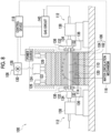
- the forming apparatus 100 includes a forming die 106 composed of a pair of lower die 102 and upper die 104, an upper die drive mechanism 108 for moving the upper die 104, a pair of pipe holding mechanisms 112 for holding both end portions of a raw pipe 110 which is a raw material of the beam material 18, a water circulation mechanism 116 for circulating cooling water through a cooling water passage 114 formed in the interior of the forming die 106, and a control device 118 for controlling them.
- the forming die 106 is provided with a cavity 120 that forms a space of a target shape to be formed when the lower die 102 and the upper die 104 are in a die closing position (refer to Fig. 9C as well).
- the cavity 120 includes a main cavity portion 120a for forming the portion other than the flange portion 28 of the beam material 18, and a sub-cavity portion 120b for forming the flange portion 28 of the beam material 18.
- the upper die drive mechanism 108 includes a slider 122 that moves the upper die 104, a main cylinder 124 that pressurizes the slider 122 downward, a pull-back cylinder 126 that pulls back the slider 122 upward, a hydraulic pump 128 that supplies pressure oil to the main cylinder 124, and a servomotor 130 that controls the hydraulic pump 128.
- the pipe holding mechanism 112 is disposed by one on each of the right-left both sides of the forming die 106.
- the pipe holding mechanism 112 includes a pair of electrodes 132 that grip the end portions of the raw pipe 110, a nozzle 134 that supplies a compressed gas into the raw pipe 110, an electrode mounting unit 136 that supports each of the pair of electrodes 132 so as to be able to individually drive the electrodes 132, and a nozzle mounting unit 138 that supports the nozzle 134 so as to be able to move it forward and backward.
- the nozzle 134 is connected to a gas circuit 140 that supplies and discharges the compressed gas.
- Figs. 9A , 9B, and 9C will be referred to.
- the outline of a hot air blow forming method using the forming apparatus 100 described above will be described.
- the beam material 18 can be obtained by hot air blow forming in which the raw pipe 110 is blow-formed with a compressed gas in a heated state, by the forming apparatus 100.
- the following operations of the forming apparatus 100 are performed under the control of the control device 118.
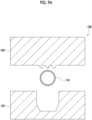
- the raw pipe 110 is disposed between the lower die 102 and the upper die 104 of the forming die 106 (refer to Fig. 9A ).
- the raw pipe 110 is gripped by the pair of electrodes 132 by moving the pair of electrodes 132 by the electrode mounting unit 136.
- the electrode 132 of the individual pipe holding mechanism 112 is energized to heat the raw pipe 110 by Joule heating.
- the raw pipe 110 is heated to a temperature range equal to or higher than an Ac3 transformation point temperature in order to quench the raw pipe 110.
- the nozzle 134 is advanced such that the nozzle 134 is inserted into each end portion of the raw pipe 110, by controlling the nozzle mounting unit 138.
- the die closing of the forming die 106 is performed by lowering the upper die 104 until it is disposed at a die closing position Pa, by controlling the servomotor 130 of the upper die drive mechanism 08.
- a low-pressure compressed gas is supplied from the nozzle 134 into the raw pipe 110 in a state before the forming die 106 is completely closed, and the blow forming is started.
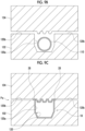
- Fig. 9B shows a state immediately before the blow forming is started. Since the raw pipe 110 is softened by the Joule heating, it can be easily expanded by the compressed gas. In this way, the raw pipe 110 expands in the main cavity portion 120a and expands so as to enter the sub-cavity portion 120b.
- the die closing of the forming die 106 is completed (refer to Fig. 9C ).
- a part of the raw pipe 110 is pressed by the lower die 102 and the upper die 104 in the sub-cavity portion 120b, so that the flange portion 28 of the beam material 18 is formed.
- a high-pressure compressed gas is supplied from the nozzle 134 into the raw pipe 110.
- the raw pipe 110 expands such that the location other than the flange portion 28 of the beam material 18 comes into contact with the main cavity portion 120a in the entire area of the main cavity portion 120a.
- the location other than the flange portion 28 of the beam material 18 is formed in the main cavity portion 120a.
- the forming die 106 is cooled by the cooling water that is circulated by the water circulation mechanism 116.
- the raw pipe 110 is quenched by die cooling by coming into contact with the cooled forming die 106.
- the supply of the compressed gas is stopped, the gripping state by the pair of electrodes 132 is released, and then the upper die 104 is raised. Thereafter, the formed beam material 18 is taken out from the forming apparatus 100.
- the reinforcing unit 10 may be a bumper beam that is used for a rear bumper that is disposed on the rear side with respect to the main body frame 12. Further, up to here, the example has been described in which the reinforcing unit 10 is disposed on the outside in the front-rear direction X as the first specific direction A with respect to the main body frame 12. In addition to this, the first specific direction A may be the right-left direction Y. In this case, the reinforcing unit 10 is disposed on the outside in the right-left direction Y with respect to the main body frame 12. This assumes a case where the reinforcing unit 10 is a bumper beam that is used for a side bumper.
- the beam material 18 is a molding product that is obtained by the hot air blow forming.
- the beam material 18 may be obtained by hydrofoam forming.
- the beam material 18 having a continuously closed cross-sectional shape is obtained.
- the beam material 18 may be configured with a welded joint product that is obtained by welding abutting locations of a plurality of metal plates made of pressed products.
- the flange portion 28 of the beam material 18 may be omitted.
- the flange portion 28 of the beam material 18 may be formed at an intermediate portion in the first specific direction A of each of the side surface portions 26A and 26B of the beam material 18.
- the reinforcing members 20A and 20B only need to cover the side surface portions 26A and 26B of the beam material 18 from the outside so as to be able to restrain the bulging deformation of at least the side surface portions 26A and 26B, and the specific shape thereof is not particularly limited.
- the reinforcing members 20A and 20B may cover the central portion 22a of the inner surface portion 22 of the beam material 18 from the frame side Sa.
- the reinforcing members 20A and 20B do not need to be provided with the receiving portion 44.
- the reinforcing members 20A and 20B may be provided with only the side plate portion 40 and do not need to be provided with the inner plate portion 42.
- the reinforcing unit 10 only needs to include one or more reinforcing members 20A and 20B, and the number thereof is not particularly limited.
- the number of reinforcing members 20A and 20B may be only one or may be three or more. Further, both the upper side surface portion 26A and the lower side surface portion 26B of the beam material 18 may be covered from the outside by one reinforcing member 20A or 20B.
- the cross section orthogonal to the longitudinal direction C of the beam material 18 does not need to have a closed cross-sectional shape and may have an open cross-sectional shape that is open in any direction. Further, the beam material 18 may include only one of the pair of side surface portions 26A and 26B, in addition to the inner surface portion 22 and the outer surface portion 24.
- a first item in the following description corresponds to the content of the Solution to Problem.
- the reinforcing unit in which the beam material includes a flange portion that is formed at the side surface portion and protrudes outward in the up-down direction, and the reinforcing member includes a side plate portion that covers the side surface portion from the outside in the up-down direction, and a receiving portion that is provided at an outer end portion on the counter-frame side of the side plate portion and disposed on the frame side with respect to the flange portion.
- the reinforcing unit according to any one of the first to third items, in which the reinforcing member includes a side plate portion that covers the side surface portion from the outside in the up-down direction, and an inner plate portion that is disposed on the frame side with respect to the inner surface portion.
- the side surface portion includes an upper side surface portion and a lower side surface portion
- one or more reinforcing members include an upper reinforcing member that covers the upper side surface portion from the outside, and a lower reinforcing member that covers the lower side surface portion from the outside and is a separate body from the upper reinforcing member.
- the present disclosure relates to a reinforcing unit.
Landscapes
- Engineering & Computer Science (AREA)
- Mechanical Engineering (AREA)
- Chemical & Material Sciences (AREA)
- Combustion & Propulsion (AREA)
- Transportation (AREA)
- Body Structure For Vehicles (AREA)
- Chair Legs, Seat Parts, And Backrests (AREA)
- Casings For Electric Apparatus (AREA)
Abstract
Description
- The present disclosure relates to a reinforcing unit.
- A reinforcing unit such as a bumper beam is sometimes incorporated into a structure such as a vehicle in order to reduce impact that occurs at the time of collision with an external object. The reinforcing unit usually includes a beam material that is mounted on a main body frame such as a vehicle body frame.
- [PTL 1]
Japanese Unexamined Patent Publication No. 2003-237507 - The reinforcing unit sometimes includes, in addition to the beam material, a reinforcing member that reinforces the beam material in order to improve impact absorption performance (refer to, for example,
PTL 1 1). The inventors of the present application have found a new idea for obtaining good impact absorption performance in such a reinforcing unit. - One object of the present disclosure is to provide a technique capable of obtaining good impact absorption performance in a reinforcing unit.
- A reinforcing unit of the present disclosure is a reinforcing unit that is mounted on a main body frame, including: a beam material; and one or more reinforcing members that are mounted on the beam material, in which the beam material includes an inner surface portion that is provided on a frame side where the main body frame is located, an outer surface portion that is provided on a counter-frame side that is a side opposite to the main body frame, and a side surface portion that connects the inner surface portion and the outer surface portion, and the reinforcing member suppresses bulging deformation of the side surface portion in a case where an impact load is input to the outer surface portion.
- A reinforcing member of the present disclosure is a reinforcing member that is mounted on a main body frame, in which the beam material includes an inner surface portion that is provided on a frame side where the main body frame is located, an outer surface portion that is provided on a counter-frame side that is a side opposite to the main body frame, and a side surface portion that connects the inner surface portion and the outer surface portion, and the reinforcing member suppresses bulging deformation of the side surface portion in a case where an impact load is input to the outer surface portion.
- According to the present disclosure, it is possible to obtain good impact absorption performance in the reinforcing unit.
-
-
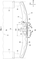
Fig. 1 is a top view of a reinforcing unit of an embodiment. -
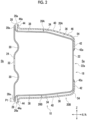
Fig. 2 is a sectional view taken along line II-II ofFig. 1 . -
Fig. 3 is a diagram schematically showing a part of an end surface along line III-III ofFig. 1 . -
Fig. 4A is an end view schematically showing a reinforcing member of a reference form. -
Fig. 4B is a diagram schematically showing a state where the reinforcing member of the reference form is being deformed. -
Fig. 4C is a diagram schematically showing a state where the reinforcing member of the reference form is being deformed. -
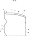
Fig. 5A is an end view schematically showing the reinforcing member of the embodiment. -
Fig. 5B is a first explanatory diagram schematically showing a state where the reinforcing member of the embodiment is being deformed. -
Fig. 5C is a second explanatory diagram schematically showing a state where the reinforcing member of the embodiment is being deformed. -
Fig. 5D is a third explanatory diagram schematically showing a state where the reinforcing member of the embodiment is being deformed. -
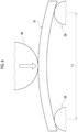
Fig. 6 is a schematic diagram showing a calculation model that is a prerequisite in FEM analysis. -
Fig. 7 is a graph showing a relationship between a reaction force obtained by the FEM analysis and a stroke amount. -
Fig. 8 is a configuration diagram showing a forming apparatus of the embodiment. -
Fig. 9A is a first explanatory diagram schematically showing a forming method of the embodiment. -
Fig. 9B is a second explanatory diagram schematically showing the forming method of the embodiment -
Fig. 9C is a third explanatory diagram schematically showing the forming method of the embodiment. - Hereinafter, an embodiment will be described. The same components are denoted by the same reference numerals, and overlapping description is omitted. In each drawing, for convenience of description, the components are appropriately omitted, enlarged, or reduced. The drawings shall be viewed according to the directions of the symbols.
-
Figs. 1 and2 will be referred to. A reinforcingunit 10 is mounted on amain body frame 12 that is a part of a structure. Themain body frame 12 supports the other portions of the structure. In the present embodiment, an example will be described in which the structure is a vehicle such as an automobile and themain body frame 12 is a vehicle body frame that supports the other portions of the vehicle. A specific example of the structure is not particularly limited and may be, for example, a crane. The reinforcingunit 10 of the present embodiment is a bumper beam that is used for a front bumper of a vehicle. Themain body frame 12 in the present embodiment includes a pair of right andleft side members 14 and a cross member (not shown) that connects the pair ofside members 14. The reinforcingunit 10 is mounted on themain body frame 12 through a crash can 16. - Hereinafter, the positional relationship of the reinforcing
unit 10 will be described using a front-rear direction X, a right-left direction Y, and an up-down direction Z which are orthogonal to each other. In a case where the reinforcingunit 10 is used in a vehicle, these directions X, Y, and Z correspond to the front-rear direction, right-left direction, and up-down direction of the vehicle. In this case, the front-rear direction X and the right-left direction Y are horizontal directions orthogonal to each other. The up-down direction Z is a vertical direction. One of the front-rear direction X and the right-left direction Y is defined as a first specific direction A, and the other is defined as a second specific direction B. The up-down direction Z is defined as a third specific direction. The reinforcingunit 10 is disposed on the outside in the first specific direction A with respect to themain body frame 12. The first specific direction A in the present embodiment is the front-rear direction X. The outside in the first specific direction A refers to the side (the front side in the present embodiment) away from themain body frame 12 in the first specific direction A. Hereinafter, the side where themain body frame 12 is located with respect to the reinforcingunit 10 in the first specific direction A is referred to as a frame side Sa (the rear side in the present embodiment). Further, the side opposite to themain body frame 12 in the first specific direction A is referred to as a counter-frame side Sb (the front side in the present embodiment). It can be said that the second specific direction B is a direction in which a beam material 18 (described later) extends as a whole, the first specific direction A is a direction of coming close to or going away from themain body frame 12, which is orthogonally to the second specific direction B, and the third specific direction (the up-down direction Z) is a direction orthogonal to these directions. - The reinforcing
unit 10 has a role of absorbing impact occurring at the time of collision with an external object. The reinforcingunit 10 includes thebeam material 18 that is mounted on themain body frame 12, and one or more reinforcingmembers beam material 18. The reinforcingmembers beam material 18. - The
beam material 18 is a long body extending in the second specific direction B (the right-left direction Y in the present embodiment) as a whole. Thebeam material 18 has an arc shape that protrudes to the counter-frame side Sb as a whole. Each of both end portions of thebeam material 18 is fixed to themain body frame 12. - The cross section orthogonal to a longitudinal direction C of the
beam material 18 has a closed cross-sectional shape, and has a polygonal shape as a whole. Thebeam material 18 in the present embodiment has a continuously closed cross-sectional shape that is seamlessly continuous in a range over the entire circumference around the center line thereof. It can be said that thebeam material 18 is configured with a single pipe material. The thickness of thebeam material 18 is not particularly limited. However, it is, for example, 1.0 mm or more and 2.3 mm or less. - The
beam material 18 is made of, for example, a steel material such as high-strength steel or ultra-high-strength steel, that is, metal. The microstructure of thebeam material 18 has a hardened structure such as α-martensite or a tempered structure such as sorbite or troostite, as a main phase. - The
beam material 18 having a continuously closed cross-sectional shape and having such a microstructure as a main phase is configured with an integral molding product that is obtained by hot air blow forming (described later). - The
beam material 18 is provided with aninner surface portion 22 that is provided on the frame side Sa, anouter surface portion 24 that is provided on the counter-frame side Sb, a pair ofside surface portions inner surface portion 22 and theouter surface portion 24, and aflange portion 28 that is formed at theside surface portions - The
inner surface portion 22 has a plate shape facing the frame side Sa as a whole. Theouter surface portion 24 has a plate shape facing the counter-frame side Sb as a whole. Theinner surface portion 22 and theouter surface portion 24 face each other in the first specific direction A (the front-rear direction X). - The
outer surface portion 24 functions as a surface that antecedently receives an impact load when an external object collides with the reinforcingunit 10 from the counter-frame side Sb. Theouter surface portion 24 is provided with a plurality ofgroove portions 30 extending along the longitudinal direction of thebeam material 18. The plurality ofgroove portions 30 contribute to improvement of the impact absorption performance by improvement of the cross-sectional performance of theouter surface portion 24. The plurality ofgroove portions 30 are recessed to the frame side Sa in theouter surface portion 24. A through-hole 32 through which a fastening member such as a bolt passes may be formed in theouter surface portion 24. - The pair of
side surface portions side surface portion 26A that is disposed on the upper side and a lowerside surface portion 26B that is disposed on the lower side. Each of theside surface portions corner portion 34 that is convex outward in the up-down direction Z, a frame-side surface portion 36 that extends from thecorner portion 34 to the frame side Sa, and a counter-frame-side surface portion 38 that extends from thecorner portion 34 to the counter-frame side Sb. Thecorner portion 34 of each of theside surface portions beam material 18 when viewed from the up-down direction Z (refer toFig. 1 ). - The
flange portion 28 contributes to the improvement of the impact absorption performance by the improvement of the cross-sectional performance of thebeam material 18. Theflange portion 28 protrudes outward in the up-down direction Z from theside surface portions beam material 18. Theflange portion 28 is formed by bending a part of thebeam material 18 so as to be folded. Theflange portion 28 in the present embodiment is formed atend portions 26a on the counter-frame side of theside surface portions portion 28a on the counter-frame side Sb of theflange portion 28 is continuous with theouter surface portion 24 as a part of theouter surface portion 24. - In the
beam material 18 that is obtained by the hot air blow forming, the protrusion amount P1 of theflange portion 28 can be set to, for example, 5 mm or less in a case where it is not provided for the purpose of welding. This means that the protrusion amount P1 is set to a size smaller than the protrusion amount (in a range of about 15 mm to 20 mm) of ageneral flange portion 28 required as a spot welding margin. This spot welding margin is required in a case where thebeam material 18 is obtained by welding a plurality of metal plates. The protrusion amount P1 here means the dimension in the up-down direction Z of the location where a part of thebeam material 18 is folded in theflange portion 28. - In the present embodiment, one or more reinforcing
members member 20A and a lower reinforcingmember 20B that is a separate body from the upper reinforcingmember 20A. Since the configuration of the lower reinforcingmember 20B when viewed from below is the same as the configuration of the upper reinforcingmember 20A when viewed from above, the illustration thereof is omitted here. - The upper reinforcing
member 20A covers the upperside surface portion 26A of thebeam material 18 from the outside (the upper side) in the up-down direction Z. The upper reinforcingmember 20A is provided along the upperside surface portion 26A of thebeam material 18. The upper reinforcingmember 20A is provided to extend in the longitudinal direction C of thebeam material 18 along the upperside surface portion 26A of thebeam material 18. The lower reinforcingmember 20B covers the lowerside surface portion 26B of thebeam material 18 from the outside (the lower side) in the up-down direction Z. The lower reinforcingmember 20B is provided along the lowerside surface portion 26B of thebeam material 18. The lower reinforcingmember 20B is provided to extend in the longitudinal direction C of thebeam material 18 along the lowerside surface portion 26B of thebeam material 18. The upper reinforcingmember 20A and the lower reinforcingmember 20B are disposed with a gap therebetween in the up-down direction Z. Each of the reinforcingmembers - The reinforcing
members beam material 18 in a part of the range in the longitudinal direction C of thebeam material 18. The reinforcingmembers central portion 18a in the longitudinal direction of thebeam material 18, which is easily deformed at the time of collision with an external object. The dimension in the right-left direction Y (the second specific direction B) of thebeam material 18 is defined as a dimension La. At this time, the reinforcingmembers beam material 18 in a range in the second specific direction B, which is equal to or smaller than half of the dimension La. - The reinforcing
members outer surface portion 24 of thebeam material 18 from the counter-frame side Sb. That is, the reinforcingmembers outer surface portion 24 of thebeam material 18 on the counter-frame side Sb. - Each of the reinforcing
members side plate portion 40 that covers each of theside surface portions beam material 18 from the outside in the up-down direction Z, aninner plate portion 42 that is disposed on the frame side Sa with respect to theinner surface portion 22 of thebeam material 18, and a receivingportion 44 that is provided at anouter end portion 40a that is located on the counter-frame side Sb of theside plate portion 40. - The
side plate portion 40 extends from the frame side Sa toward the counter-frame side Sb. Theside plate portion 40 covers each of theside surface portions corner portion 34 of thebeam material 18. -
Figs. 1 and3 will be referred to. Theside plate portion 40 is formed such that aprotrusion portion 46 and a recessedportion 48 that undulate in the up-down direction Z are alternately arranged in the right-left direction Y (the second specific direction B). Theprotrusion portion 46 protrudes to the outside in the up-down direction Z (the side away from the beam material 18). The recessedportion 48 is recessed to the inside in the up-down direction Z (the side approaching the beam material 18). In the present embodiment, threeprotrusion portions 46 and two recessedportions 48 are formed so as to be arranged alternately. Awelding hole 50 is formed in the recessedportion 48. The recessedportion 48 is in contact with the counter-frame-side surface portion 38 of thebeam material 18, and theprotrusion portion 46 is disposed at an interval with respect to thebeam material 18. Theside plate portion 40 is fixed to each of theside surface portions beam material 18 by welding the inner peripheral portion of thewelding hole 50. - The
side plate portion 40 is provided with adimension change portion 52 that gradually reduces a dimension in the right-left direction Y (the second specific direction B) as it goes toward the frame side Sa. Thedimension change portion 52 in the present embodiment is provided in a continuous range from the end portion of the frame side Sa toward the counter-frame side Sb in theside plate portion 40. - The maximum dimension in the right-left direction Y (the second specific direction B) of the
side plate portion 40 is set to be Lma, and the maximum dimension in the right-left direction Y (the second specific direction B) of theinner plate portion 42 is set to be Lmb. In the present embodiment, the maximum dimension Lmb of theinner plate portion 42 is a size equal to or less than half of the maximum dimension Lma of theside plate portion 40. -
Fig. 2 will be referred to. Theinner plate portion 42 is connected to theside plate portion 40 through abent portion 54, and thus theside plate portion 40 and theinner plate portion 42 form an L shape as a whole. Theinner plate portion 42 covers an edge portion in the up-down direction Z of theinner surface portion 22 of thebeam material 18 from the frame side Sa, and does not cover acentral portion 22a in the up-down direction Z of theinner surface portion 22 from the frame side Sa. That is, theinner plate portion 42 is not disposed at a position overlapping thecentral portion 22a of theinner surface portion 22 of thebeam material 18 in the front-rear direction X (the first specific direction A). - The
inner plate portion 42 is continuous with theprotrusion portion 46 that is located on the center side in the right-left direction Y (the second specific direction B) of theside plate portion 40. Theinner plate portion 42 is fixed to theinner surface portion 22 of thebeam material 18 by line-welding anend edge portion 42a of theinner plate portion 42. - The receiving
portion 44 is formed by bending theouter end portion 40a of theside plate portion 40 outward in the up-down direction Z. The receivingportion 44 is disposed at an interval with respect to theflange portion 28 of thebeam material 18 on the frame side Sa. The receivingportion 44 is provided with asurface portion 44a that is located at a position overlapping theflange portion 28 in the front-rear direction X (the first specific direction A) and faces theflange portion 28 in the front-rear direction X. As will be described later, the receivingportion 44 has a role of receiving theflange portion 28 of thebeam material 18 when theflange portion 28 tries to be displaced to the frame side Sa. From such a relationship, the receivingportion 44 is provided in the vicinity of theflange portion 28 of thebeam material 18. The receivingportion 44 is provided on the counter-frame side Sb with respect to thecorner portion 34 of each of theside surface portions beam material 18. - Next, the operation and effect of the reinforcing
unit 10 will be described. - First, the deformation behavior of a reinforcing
unit 10 of a reference form will be described.Figs. 4A ,4B , and4C will be referred to. The reinforcingunit 10 of the reference form is provided with thebeam material 18 having the same structure as that in the embodiment, and is not provided with the reinforcingmembers outer surface portion 24 of thebeam material 18, theside surface portions beam material 18 are subjected to bulging deformation so as to bulge in an outward direction Da in the up-down direction (refer to a range Sl). At this time, in a case where thebeam material 18 has theflange portion 28, the bulging deformation of theside surface portions corner portions 34 of theside surface portions beam material 18 does not have theflange portion 28. This is a knowledge newly obtained by an analytical method. - Next, the deformation behavior of the reinforcing
unit 10 of the embodiment will be described.Figs. 5A ,5B ,5C , and5D will be referred to. Here, the relationship between the upperside surface portion 26A of thebeam material 18 and the upper reinforcingmember 20A is shown. The following description also applies in common to the relationship between the lowerside surface portion 26B of thebeam material 18 and the lower reinforcingmember 20B. - As described above, in a case where the impact load Fa is input to the
outer surface portion 24 of thebeam material 18, theside surface portions beam material 18 try to perform bulging deformation in the outward direction Da in the up-down direction. At this time, theside plate portions 40 of the reinforcingmembers side surface portions beam material 18 from the outside, thereby restraining the bulging deformation (refer to a range S2). That is, theside plate portions 40 of the reinforcingmembers side surface portions beam material 18. In this way, the early progress of plastic deformation in a local range in the longitudinal direction C of theouter surface portion 24 of thebeam material 18 can be suppressed, and the plastic deformation of thebeam material 18 in a wider range in the longitudinal direction C can be promoted. Eventually, good impact absorption performance of the reinforcingunit 10 as a whole can be obtained. - Here, with the progress of the bulging deformation of the
side surface portions beam material 18, theflange portion 28 of thebeam material 18 is displaced to the frame side Sa (refer toFig. 5B ). According to this, theflange portion 28 of thebeam material 18 hits against theouter end portions 40a of theside plate portions 40 of the reinforcingmembers flange portion 28 of thebeam material 18 hits against the receivingportions 44 of the reinforcingmembers flange portion 28 of thebeam material 18 is displaced to the frame side Sa, so that theouter end portions 40a of the reinforcingmembers flange portion 28 of thebeam material 18. In this way, the movement of theouter end portions 40a of the reinforcingmembers flange portion 28 of the beam material 18 (refer toFig. 5C ). Therefore, the reinforcingmembers side surface portions beam material 18 in a state where the movement at theouter end portion 40a is restrained. At this time, while the side plate portions 40A of the reinforcingmembers side surface portions beam material 18, the side plate portions 40A perform bulging deformation in the outward direction Da in the up-down direction to follow the bulging deformation of theside surface portions Fig. 5D ). - In this way, the effect of restraining the bulging deformation of the
beam material 18 by the reinforcingmembers unit 10 as a whole can be stably obtained. This effect can be obtained even without the receivingportions 44 of the reinforcingmembers portions 44, it becomes easy to stably obtain the effect. - In this manner, in the reinforcing
unit 10 of the embodiment, thebeam material 18 is plastically deformed antecedently instead of the reinforcingmembers unit 10 of the embodiment, the bulging deformation of theside surface portions beam material 18 according to the preceding plastic deformation of thebeam material 18 is restrained by the reinforcingmembers unit 10 as a whole is obtained. - In obtaining good impact absorption performance in this manner, the reinforcing
members outer surface portion 24 of thebeam material 18 from the counter-frame side Sb. Further, in obtaining good impact absorption performance in this manner, it is enough if only a local location such as the outside of theside surface portions beam material 18 in the cross section orthogonal to the longitudinal direction C is covered. Therefore, the range of covering thebeam material 18 with the reinforcingmembers unit 10 as a whole can be attained. - In obtaining good impact absorption performance in this manner, it is not necessary to cover the
central portion 22a of theinner surface portion 22 of thebeam material 18 from the frame side Sa. Also in this respect, the range of covering thebeam material 18 with the reinforcingmembers unit 10 as a whole can be attained. - As described above, in a case where the
beam material 18 has theflange portion 28, the bulging deformation of theside surface portions beam material 18 easily occurs with thecorner portions 34 of theside surface portions flange portion 28 and thecorner portion 34 are provided in theside surface portions beam material 18, it becomes easy to control the location where the bulging deformation occurs in theside surface portions beam material 18 by the reinforcingmembers - Each of the reinforcing
members inner plate portion 42 that is disposed on the frame side Sa with respect to theinner surface portion 22 of thebeam material 18, in addition to theside plate portion 40 that covers each of theside surface portions beam material 18. Therefore, when theside plate portions 40 of the reinforcingmembers side surface portions beam material 18, the bending deformation of theside plate portion 40 can be restrained by theinner plate portion 42. In this way, for example, the early progress of deformation of the reinforcingmembers side plate portions 40 of the reinforcingmembers beam material 18 by the reinforcingmembers unit 10 as a whole can be stably obtained. - One or more reinforcing
members member 20A and the lower reinforcingmember 20B that is a separate body from the upper reinforcingmember 20A. Therefore, the upperside surface portion 26A and the lowerside surface portion 26B of thebeam material 18 are covered with the individual reinforcingmembers side surface portions unit 10 as a whole can be obtained. - Along with this, the range of covering the
inner surface portion 22 of thebeam material 18 by the reinforcingmembers side surface portion 26A and the lowerside surface portion 26B of thebeam material 18 are covered with a common reinforcing material. Eventually, the weight saving of the reinforcingunit 10 as a whole can be attained. - Next, the analysis performed in order to explain the effect of the reinforcing
unit 10 of the embodiment will be described.Fig. 6 will be referred to. In this analysis, LS-DYNA was used as analysis software, and FEM analysis reproducing a three-point bending test was performed. Both end portions of the reinforcingunit 10 were supported byrigid bodies 56 with a distance L1 between fulcrums being set to 892 mm. A load was applied from arigid body 58 to the central portion of the reinforcingunit 10 under the conditions of a speed of 0.5 mm/sec and a maximum stroke of 100 mm. -
Fig. 7 will be referred to. It is shown that the larger the reaction force (kN) inFig. 7 , the larger the impact absorption performance. The FEM analysis was performed on each of the reinforcingunit 10 of the embodiment described above and the reinforcingunit 10 of the reference form. The data of "with reinforcing member" inFig. 7 is for the reinforcingunit 10 of the embodiment, and the data of "without reinforcing member" inFig. 7 is for the reinforcingunit 10 of the reference form. As shown inFig. 7 , it can be seen that the reaction force (impact absorption performance) greatly changes according to the presence or absence of the reinforcingmembers members -
Fig. 8 will be referred to. A formingapparatus 100 for forming thebeam material 18 described above will be described. The formingapparatus 100 includes a formingdie 106 composed of a pair oflower die 102 andupper die 104, an upperdie drive mechanism 108 for moving theupper die 104, a pair ofpipe holding mechanisms 112 for holding both end portions of araw pipe 110 which is a raw material of thebeam material 18, awater circulation mechanism 116 for circulating cooling water through a coolingwater passage 114 formed in the interior of the formingdie 106, and acontrol device 118 for controlling them. - The forming
die 106 is provided with acavity 120 that forms a space of a target shape to be formed when thelower die 102 and theupper die 104 are in a die closing position (refer toFig. 9C as well). Thecavity 120 includes amain cavity portion 120a for forming the portion other than theflange portion 28 of thebeam material 18, and asub-cavity portion 120b for forming theflange portion 28 of thebeam material 18. - The upper
die drive mechanism 108 includes aslider 122 that moves theupper die 104, amain cylinder 124 that pressurizes theslider 122 downward, a pull-back cylinder 126 that pulls back theslider 122 upward, ahydraulic pump 128 that supplies pressure oil to themain cylinder 124, and aservomotor 130 that controls thehydraulic pump 128. - The
pipe holding mechanism 112 is disposed by one on each of the right-left both sides of the formingdie 106. Thepipe holding mechanism 112 includes a pair ofelectrodes 132 that grip the end portions of theraw pipe 110, anozzle 134 that supplies a compressed gas into theraw pipe 110, anelectrode mounting unit 136 that supports each of the pair ofelectrodes 132 so as to be able to individually drive theelectrodes 132, and anozzle mounting unit 138 that supports thenozzle 134 so as to be able to move it forward and backward. Thenozzle 134 is connected to agas circuit 140 that supplies and discharges the compressed gas. -
Figs. 9A ,9B, and 9C will be referred to. The outline of a hot air blow forming method using the formingapparatus 100 described above will be described. Thebeam material 18 can be obtained by hot air blow forming in which theraw pipe 110 is blow-formed with a compressed gas in a heated state, by the formingapparatus 100. The following operations of the formingapparatus 100 are performed under the control of thecontrol device 118. - First, the
raw pipe 110 is disposed between thelower die 102 and theupper die 104 of the forming die 106 (refer toFig. 9A ). Next, theraw pipe 110 is gripped by the pair ofelectrodes 132 by moving the pair ofelectrodes 132 by theelectrode mounting unit 136. In this state, theelectrode 132 of the individualpipe holding mechanism 112 is energized to heat theraw pipe 110 by Joule heating. At this time, theraw pipe 110 is heated to a temperature range equal to or higher than an Ac3 transformation point temperature in order to quench theraw pipe 110. - Thereafter, the
nozzle 134 is advanced such that thenozzle 134 is inserted into each end portion of theraw pipe 110, by controlling thenozzle mounting unit 138. Thereafter, the die closing of the formingdie 106 is performed by lowering theupper die 104 until it is disposed at a die closing position Pa, by controlling theservomotor 130 of the upper die drive mechanism 08. At this time, a low-pressure compressed gas is supplied from thenozzle 134 into theraw pipe 110 in a state before the formingdie 106 is completely closed, and the blow forming is started.Fig. 9B shows a state immediately before the blow forming is started. Since theraw pipe 110 is softened by the Joule heating, it can be easily expanded by the compressed gas. In this way, theraw pipe 110 expands in themain cavity portion 120a and expands so as to enter thesub-cavity portion 120b. - Thereafter, when the
upper die 104 is lowered to the die closing position Pa, the die closing of the formingdie 106 is completed (refer toFig. 9C ). In this way, a part of theraw pipe 110 is pressed by thelower die 102 and theupper die 104 in thesub-cavity portion 120b, so that theflange portion 28 of thebeam material 18 is formed. Thereafter, a high-pressure compressed gas is supplied from thenozzle 134 into theraw pipe 110. In this way, theraw pipe 110 expands such that the location other than theflange portion 28 of thebeam material 18 comes into contact with themain cavity portion 120a in the entire area of themain cavity portion 120a. As a result, the location other than theflange portion 28 of thebeam material 18 is formed in themain cavity portion 120a. - In the above blow forming process, the forming
die 106 is cooled by the cooling water that is circulated by thewater circulation mechanism 116. Theraw pipe 110 is quenched by die cooling by coming into contact with the cooled formingdie 106. - Thereafter, the supply of the compressed gas is stopped, the gripping state by the pair of
electrodes 132 is released, and then theupper die 104 is raised. Thereafter, the formedbeam material 18 is taken out from the formingapparatus 100. - Other modification forms of each component will be described.
- The reinforcing
unit 10 may be a bumper beam that is used for a rear bumper that is disposed on the rear side with respect to themain body frame 12. Further, up to here, the example has been described in which the reinforcingunit 10 is disposed on the outside in the front-rear direction X as the first specific direction A with respect to themain body frame 12. In addition to this, the first specific direction A may be the right-left direction Y. In this case, the reinforcingunit 10 is disposed on the outside in the right-left direction Y with respect to themain body frame 12. This assumes a case where the reinforcingunit 10 is a bumper beam that is used for a side bumper. - The example has been described in which the
beam material 18 is a molding product that is obtained by the hot air blow forming. In addition to this, thebeam material 18 may be obtained by hydrofoam forming. In this case, thebeam material 18 having a continuously closed cross-sectional shape is obtained. In addition to this, thebeam material 18 may be configured with a welded joint product that is obtained by welding abutting locations of a plurality of metal plates made of pressed products. - The
flange portion 28 of thebeam material 18 may be omitted. Theflange portion 28 of thebeam material 18 may be formed at an intermediate portion in the first specific direction A of each of theside surface portions beam material 18. - The reinforcing
members side surface portions beam material 18 from the outside so as to be able to restrain the bulging deformation of at least theside surface portions members central portion 22a of theinner surface portion 22 of thebeam material 18 from the frame side Sa. Further, the reinforcingmembers portion 44. Further, the reinforcingmembers side plate portion 40 and do not need to be provided with theinner plate portion 42. - The reinforcing
unit 10 only needs to include one or more reinforcingmembers members side surface portion 26A and the lowerside surface portion 26B of thebeam material 18 may be covered from the outside by one reinforcingmember - The cross section orthogonal to the longitudinal direction C of the
beam material 18 does not need to have a closed cross-sectional shape and may have an open cross-sectional shape that is open in any direction. Further, thebeam material 18 may include only one of the pair ofside surface portions inner surface portion 22 and theouter surface portion 24. - The above embodiment and modification forms are exemplification. The technical ideas that abstract these examples should not be construed to be limited to the contents of the embodiment and modification forms. Many design changes such as change, addition, and deletion of components can be made in the contents of the embodiment and modification forms. In the embodiment described above, the content in which such a design changes can be made is emphasized by adding a notation "embodiment". However, design changes are allowed even in a content in which there is no such notation. The hatching made in the cross section of the drawing does not limit the material of the object in which the hatching is made.
- When the above-disclosed contents are abstracted, the technical ideas described in the following items can be grasped. A first item in the following description corresponds to the content of the Solution to Problem.
- (Second item) The reinforcing unit according to the first item, in which the reinforcing member does not cover the outer surface portion from the counter-frame side and covers the side surface portion from the outside in the up-down direction.
- (Third item) The reinforcing unit according to the first or second item, in which the beam material includes a flange portion that is formed at the side surface portion and protrudes outward in the up-down direction, and the reinforcing member includes a side plate portion that covers the side surface portion from the outside in the up-down direction, and a receiving portion that is provided at an outer end portion on the counter-frame side of the side plate portion and disposed on the frame side with respect to the flange portion.
- (Fourth item) The reinforcing unit according to any one of the first to third items, in which the reinforcing member includes a side plate portion that covers the side surface portion from the outside in the up-down direction, and an inner plate portion that is disposed on the frame side with respect to the inner surface portion.
- (Fifth item) The reinforcing unit according to any one of the first to fourth items, in which the reinforcing member does not cover a central portion in the up-down direction of the inner surface portion from the frame side.
- (Sixth item) The side surface portion includes an upper side surface portion and a lower side surface portion, and one or more reinforcing members include an upper reinforcing member that covers the upper side surface portion from the outside, and a lower reinforcing member that covers the lower side surface portion from the outside and is a separate body from the upper reinforcing member.
- The present disclosure relates to a reinforcing unit.
-
- 10
- reinforcing unit
- 12
- main body frame
- 18
- beam material
- 18a
- central portion
- 20A
- upper reinforcing member
- 20B
- lower reinforcing member
- 22
- inner surface portion
- 24
- outer surface portion
- 26A
- upper side surface portion
- 26B
- lower side surface portion
- 28
- flange portion
- 40
- side plate portion
- 40a
- outer end portion
- 42
- inner plate portion
- 44
- receiving portion.
Claims (6)
- A reinforcing unit that is mounted on a main body frame, comprising:a beam material; andone or more reinforcing members that are mounted on the beam material,wherein the beam material includes an inner surface portion that is provided on a frame side where the main body frame is located, an outer surface portion that is provided on a counter-frame side that is a side opposite to the main body frame, and a side surface portion that connects the inner surface portion and the outer surface portion, andthe reinforcing member suppresses bulging deformation of the side surface portion in a case where an impact load is input to the outer surface portion.
- The reinforcing unit according to claim 1, wherein the beam material has a closed cross-sectional shape.
- The reinforcing unit according to claim 1 or 2, wherein the reinforcing member is provided along the side surface portion.
- The reinforcing unit according to claim 3, wherein the reinforcing member covers the side surface portion from an outside.
- The reinforcing unit according to any one of claims 1 to 4, wherein the beam material includes a flange portion that is formed at the side surface portion and protrudes outward in an up-down direction.
- A reinforcing member that reinforces a beam material which is mounted on a main body frame,wherein the beam material includes an inner surface portion that is provided on a frame side where the main body frame is located, an outer surface portion that is provided on a counter-frame side that is a side opposite to the main body frame, and a side surface portion that connects the inner surface portion and the outer surface portion, andthe reinforcing member suppresses bulging deformation of the side surface portion in a case where an impact load is input to the outer surface portion.
Applications Claiming Priority (2)
| Application Number | Priority Date | Filing Date | Title |
|---|---|---|---|
| US202117363019A | 2021-06-30 | 2021-06-30 | |
| PCT/JP2022/018837 WO2023276430A1 (en) | 2021-06-30 | 2022-04-26 | Reinforcing unit and reinforcing member |
Publications (3)
| Publication Number | Publication Date |
|---|---|
| EP4365034A1 true EP4365034A1 (en) | 2024-05-08 |
| EP4365034A4 EP4365034A4 (en) | 2024-10-02 |
| EP4365034B1 EP4365034B1 (en) | 2026-05-06 |
Family
ID=84692715
Family Applications (1)
| Application Number | Title | Priority Date | Filing Date |
|---|---|---|---|
| EP22832590.8A Active EP4365034B1 (en) | 2021-06-30 | 2022-04-26 | Reinforcing unit |
Country Status (6)
| Country | Link |
|---|---|
| EP (1) | EP4365034B1 (en) |
| JP (1) | JPWO2023276430A1 (en) |
| KR (1) | KR20240026909A (en) |
| CN (1) | CN117460648A (en) |
| CA (1) | CA3225447A1 (en) |
| WO (1) | WO2023276430A1 (en) |
Family Cites Families (11)
| Publication number | Priority date | Publication date | Assignee | Title |
|---|---|---|---|---|
| DE10205627A1 (en) * | 2002-02-12 | 2003-08-14 | Suspa Holding Gmbh | Vehicle bumper, comprises hollow profile containing insert designed to deform in event of collison |
| JP2003237507A (en) | 2002-02-19 | 2003-08-27 | Om Kogyo Kk | Bumper reinforcement |
| JP5407372B2 (en) * | 2009-01-30 | 2014-02-05 | マツダ株式会社 | Vehicle side body structure |
| JP5440156B2 (en) * | 2009-12-25 | 2014-03-12 | マツダ株式会社 | Vehicle frame structure |
| DE102014018862B4 (en) * | 2014-12-16 | 2018-08-30 | Audi Ag | Vehicle column for a vehicle body |
| JP2017035921A (en) * | 2015-08-07 | 2017-02-16 | 豊田鉄工株式会社 | Bumper reinforcement |
| JP2018075956A (en) * | 2016-11-09 | 2018-05-17 | 豊田鉄工株式会社 | Bumper reinforcement |
| JP6704873B2 (en) * | 2017-04-07 | 2020-06-03 | 豊田鉄工株式会社 | Bumper reinforcement |
| CN110494328B (en) * | 2017-04-10 | 2023-07-04 | 日本制铁株式会社 | Structural member for automobile |
| DE112019002975B4 (en) * | 2018-06-14 | 2025-11-06 | Nippon Steel Corporation | Closed cross-section structural element with high performance in a collision and automotive body structure |
| JP7137133B2 (en) * | 2018-09-27 | 2022-09-14 | マツダ株式会社 | Vehicle side body structure |
-
2022
- 2022-04-26 CN CN202280040284.XA patent/CN117460648A/en active Pending
- 2022-04-26 JP JP2023531468A patent/JPWO2023276430A1/ja active Pending
- 2022-04-26 EP EP22832590.8A patent/EP4365034B1/en active Active
- 2022-04-26 WO PCT/JP2022/018837 patent/WO2023276430A1/en not_active Ceased
- 2022-04-26 KR KR1020237041493A patent/KR20240026909A/en active Pending
- 2022-04-26 CA CA3225447A patent/CA3225447A1/en active Pending
Also Published As
| Publication number | Publication date |
|---|---|
| EP4365034A4 (en) | 2024-10-02 |
| EP4365034B1 (en) | 2026-05-06 |
| WO2023276430A1 (en) | 2023-01-05 |
| KR20240026909A (en) | 2024-02-29 |
| CA3225447A1 (en) | 2023-01-05 |
| CN117460648A (en) | 2024-01-26 |
| JPWO2023276430A1 (en) | 2023-01-05 |
Similar Documents
| Publication | Publication Date | Title |
|---|---|---|
| JP7733088B2 (en) | Vehicle body side structural frame | |
| US11097789B2 (en) | Structural member for automobiles and method for producing the same | |
| JP6288378B2 (en) | Panel-shaped molded product, vehicle door, and method for manufacturing panel-shaped molded product | |
| JP7705384B2 (en) | Vehicle floor and corresponding manufacturing method - Patents.com | |
| KR102236841B1 (en) | Structural members and structural members for vehicles | |
| JP2023531973A (en) | Vehicle locker stiffeners and lockers | |
| US10399519B2 (en) | Vehicle bumper beam with varied strength zones | |
| CN114502297A (en) | Molded article, structural member using same, and method for producing molded article | |
| US10272948B2 (en) | Front rail for vehicle underbody assembly with varied strength zones | |
| EP4365034B1 (en) | Reinforcing unit | |
| US20240123929A1 (en) | Reinforcing unit and reinforcing member | |
| CN118019682A (en) | Floor panel and method for vehicle | |
| US10633037B2 (en) | Vehicle underbody assembly with thermally treated rear rail | |
| KR20140017324A (en) | Front side member for vehicle and method of manufacturing the same | |
| US20180363096A1 (en) | Method for forming varied strength zones of a vehicle component | |
| KR20250048685A (en) | Integral bumper beam assembly for vehicles | |
| CN114585456A (en) | Manufacturing method of molded product, molded product, and structural member using the same | |
| US11623693B2 (en) | Vehicle body |
Legal Events
| Date | Code | Title | Description |
|---|---|---|---|
| STAA | Information on the status of an ep patent application or granted ep patent |
Free format text: STATUS: THE INTERNATIONAL PUBLICATION HAS BEEN MADE |
|
| PUAI | Public reference made under article 153(3) epc to a published international application that has entered the european phase |
Free format text: ORIGINAL CODE: 0009012 |
|
| STAA | Information on the status of an ep patent application or granted ep patent |
Free format text: STATUS: REQUEST FOR EXAMINATION WAS MADE |
|
| 17P | Request for examination filed |
Effective date: 20231214 |
|
| AK | Designated contracting states |
Kind code of ref document: A1 Designated state(s): AL AT BE BG CH CY CZ DE DK EE ES FI FR GB GR HR HU IE IS IT LI LT LU LV MC MK MT NL NO PL PT RO RS SE SI SK SM TR |
|
| STAA | Information on the status of an ep patent application or granted ep patent |
Free format text: STATUS: EXAMINATION IS IN PROGRESS |
|
| A4 | Supplementary search report drawn up and despatched |
Effective date: 20240904 |
|
| RIC1 | Information provided on ipc code assigned before grant |
Ipc: B62D 21/15 20060101ALI20240829BHEP Ipc: B60R 19/04 20060101AFI20240829BHEP |
|
| DAV | Request for validation of the european patent (deleted) | ||
| DAX | Request for extension of the european patent (deleted) | ||
| 17Q | First examination report despatched |
Effective date: 20240917 |
|
| GRAP | Despatch of communication of intention to grant a patent |
Free format text: ORIGINAL CODE: EPIDOSNIGR1 |
|
| STAA | Information on the status of an ep patent application or granted ep patent |
Free format text: STATUS: GRANT OF PATENT IS INTENDED |
|
| GRAS | Grant fee paid |
Free format text: ORIGINAL CODE: EPIDOSNIGR3 |
|
| INTG | Intention to grant announced |
Effective date: 20260303 |
|
| GRAA | (expected) grant |
Free format text: ORIGINAL CODE: 0009210 |
|
| STAA | Information on the status of an ep patent application or granted ep patent |
Free format text: STATUS: THE PATENT HAS BEEN GRANTED |
|
| AK | Designated contracting states |
Kind code of ref document: B1 Designated state(s): AL AT BE BG CH CY CZ DE DK EE ES FI FR GB GR HR HU IE IS IT LI LT LU LV MC MK MT NL NO PL PT RO RS SE SI SK SM TR |
|
| REG | Reference to a national code |
Ref country code: CH Ref legal event code: F10 Free format text: ST27 STATUS EVENT CODE: U-0-0-F10-F00 (AS PROVIDED BY THE NATIONAL OFFICE) Effective date: 20260506 Ref country code: GB Ref legal event code: FG4D |