EP4364999A1 - Motor vehicle with steering wheel provided with an illuminable portion - Google Patents
Motor vehicle with steering wheel provided with an illuminable portion Download PDFInfo
- Publication number
- EP4364999A1 EP4364999A1 EP23206049.1A EP23206049A EP4364999A1 EP 4364999 A1 EP4364999 A1 EP 4364999A1 EP 23206049 A EP23206049 A EP 23206049A EP 4364999 A1 EP4364999 A1 EP 4364999A1
- Authority
- EP
- European Patent Office
- Prior art keywords
- motor vehicle
- steering wheel
- zone
- transparent portion
- activation
- Prior art date
- Legal status (The legal status is an assumption and is not a legal conclusion. Google has not performed a legal analysis and makes no representation as to the accuracy of the status listed.)
- Pending
Links
Images




Classifications
-
- B—PERFORMING OPERATIONS; TRANSPORTING
- B60—VEHICLES IN GENERAL
- B60K—ARRANGEMENT OR MOUNTING OF PROPULSION UNITS OR OF TRANSMISSIONS IN VEHICLES; ARRANGEMENT OR MOUNTING OF PLURAL DIVERSE PRIME-MOVERS IN VEHICLES; AUXILIARY DRIVES FOR VEHICLES; INSTRUMENTATION OR DASHBOARDS FOR VEHICLES; ARRANGEMENTS IN CONNECTION WITH COOLING, AIR INTAKE, GAS EXHAUST OR FUEL SUPPLY OF PROPULSION UNITS IN VEHICLES
- B60K35/00—Instruments specially adapted for vehicles; Arrangement of instruments in or on vehicles
- B60K35/10—Input arrangements, i.e. from user to vehicle, associated with vehicle functions or specially adapted therefor
-
- B—PERFORMING OPERATIONS; TRANSPORTING
- B60—VEHICLES IN GENERAL
- B60K—ARRANGEMENT OR MOUNTING OF PROPULSION UNITS OR OF TRANSMISSIONS IN VEHICLES; ARRANGEMENT OR MOUNTING OF PLURAL DIVERSE PRIME-MOVERS IN VEHICLES; AUXILIARY DRIVES FOR VEHICLES; INSTRUMENTATION OR DASHBOARDS FOR VEHICLES; ARRANGEMENTS IN CONNECTION WITH COOLING, AIR INTAKE, GAS EXHAUST OR FUEL SUPPLY OF PROPULSION UNITS IN VEHICLES
- B60K35/00—Instruments specially adapted for vehicles; Arrangement of instruments in or on vehicles
- B60K35/20—Output arrangements, i.e. from vehicle to user, associated with vehicle functions or specially adapted therefor
- B60K35/21—Output arrangements, i.e. from vehicle to user, associated with vehicle functions or specially adapted therefor using visual output, e.g. blinking lights or matrix displays
- B60K35/22—Display screens
-
- B—PERFORMING OPERATIONS; TRANSPORTING
- B60—VEHICLES IN GENERAL
- B60K—ARRANGEMENT OR MOUNTING OF PROPULSION UNITS OR OF TRANSMISSIONS IN VEHICLES; ARRANGEMENT OR MOUNTING OF PLURAL DIVERSE PRIME-MOVERS IN VEHICLES; AUXILIARY DRIVES FOR VEHICLES; INSTRUMENTATION OR DASHBOARDS FOR VEHICLES; ARRANGEMENTS IN CONNECTION WITH COOLING, AIR INTAKE, GAS EXHAUST OR FUEL SUPPLY OF PROPULSION UNITS IN VEHICLES
- B60K35/00—Instruments specially adapted for vehicles; Arrangement of instruments in or on vehicles
- B60K35/20—Output arrangements, i.e. from vehicle to user, associated with vehicle functions or specially adapted therefor
- B60K35/28—Output arrangements, i.e. from vehicle to user, associated with vehicle functions or specially adapted therefor characterised by the type of the output information, e.g. video entertainment or vehicle dynamics information; characterised by the purpose of the output information, e.g. for attracting the attention of the driver
-
- B—PERFORMING OPERATIONS; TRANSPORTING
- B60—VEHICLES IN GENERAL
- B60K—ARRANGEMENT OR MOUNTING OF PROPULSION UNITS OR OF TRANSMISSIONS IN VEHICLES; ARRANGEMENT OR MOUNTING OF PLURAL DIVERSE PRIME-MOVERS IN VEHICLES; AUXILIARY DRIVES FOR VEHICLES; INSTRUMENTATION OR DASHBOARDS FOR VEHICLES; ARRANGEMENTS IN CONNECTION WITH COOLING, AIR INTAKE, GAS EXHAUST OR FUEL SUPPLY OF PROPULSION UNITS IN VEHICLES
- B60K35/00—Instruments specially adapted for vehicles; Arrangement of instruments in or on vehicles
- B60K35/60—Instruments characterised by their location or relative disposition in or on vehicles
-
- B—PERFORMING OPERATIONS; TRANSPORTING
- B62—LAND VEHICLES FOR TRAVELLING OTHERWISE THAN ON RAILS
- B62D—MOTOR VEHICLES; TRAILERS
- B62D1/00—Steering controls, i.e. means for initiating a change of direction of the vehicle
- B62D1/02—Steering controls, i.e. means for initiating a change of direction of the vehicle vehicle-mounted
- B62D1/04—Hand wheels
-
- B—PERFORMING OPERATIONS; TRANSPORTING
- B60—VEHICLES IN GENERAL
- B60K—ARRANGEMENT OR MOUNTING OF PROPULSION UNITS OR OF TRANSMISSIONS IN VEHICLES; ARRANGEMENT OR MOUNTING OF PLURAL DIVERSE PRIME-MOVERS IN VEHICLES; AUXILIARY DRIVES FOR VEHICLES; INSTRUMENTATION OR DASHBOARDS FOR VEHICLES; ARRANGEMENTS IN CONNECTION WITH COOLING, AIR INTAKE, GAS EXHAUST OR FUEL SUPPLY OF PROPULSION UNITS IN VEHICLES
- B60K2360/00—Indexing scheme associated with groups B60K35/00 or B60K37/00 relating to details of instruments or dashboards
- B60K2360/16—Type of output information
- B60K2360/172—Driving mode indication
-
- B—PERFORMING OPERATIONS; TRANSPORTING
- B60—VEHICLES IN GENERAL
- B60K—ARRANGEMENT OR MOUNTING OF PROPULSION UNITS OR OF TRANSMISSIONS IN VEHICLES; ARRANGEMENT OR MOUNTING OF PLURAL DIVERSE PRIME-MOVERS IN VEHICLES; AUXILIARY DRIVES FOR VEHICLES; INSTRUMENTATION OR DASHBOARDS FOR VEHICLES; ARRANGEMENTS IN CONNECTION WITH COOLING, AIR INTAKE, GAS EXHAUST OR FUEL SUPPLY OF PROPULSION UNITS IN VEHICLES
- B60K2360/00—Indexing scheme associated with groups B60K35/00 or B60K37/00 relating to details of instruments or dashboards
- B60K2360/20—Optical features of instruments
- B60K2360/33—Illumination features
- B60K2360/332—Light emitting diodes
-
- B—PERFORMING OPERATIONS; TRANSPORTING
- B60—VEHICLES IN GENERAL
- B60K—ARRANGEMENT OR MOUNTING OF PROPULSION UNITS OR OF TRANSMISSIONS IN VEHICLES; ARRANGEMENT OR MOUNTING OF PLURAL DIVERSE PRIME-MOVERS IN VEHICLES; AUXILIARY DRIVES FOR VEHICLES; INSTRUMENTATION OR DASHBOARDS FOR VEHICLES; ARRANGEMENTS IN CONNECTION WITH COOLING, AIR INTAKE, GAS EXHAUST OR FUEL SUPPLY OF PROPULSION UNITS IN VEHICLES
- B60K2360/00—Indexing scheme associated with groups B60K35/00 or B60K37/00 relating to details of instruments or dashboards
- B60K2360/77—Instrument locations other than the dashboard
- B60K2360/782—Instrument locations other than the dashboard on the steering wheel
-
- B—PERFORMING OPERATIONS; TRANSPORTING
- B60—VEHICLES IN GENERAL
- B60Q—ARRANGEMENT OF SIGNALLING OR LIGHTING DEVICES, THE MOUNTING OR SUPPORTING THEREOF OR CIRCUITS THEREFOR, FOR VEHICLES IN GENERAL
- B60Q3/00—Arrangement of lighting devices for vehicle interiors; Lighting devices specially adapted for vehicle interiors
- B60Q3/20—Arrangement of lighting devices for vehicle interiors; Lighting devices specially adapted for vehicle interiors for lighting specific fittings of passenger or driving compartments; mounted on specific fittings of passenger or driving compartments
- B60Q3/283—Steering wheels; Gear levers
-
- B—PERFORMING OPERATIONS; TRANSPORTING
- B60—VEHICLES IN GENERAL
- B60Q—ARRANGEMENT OF SIGNALLING OR LIGHTING DEVICES, THE MOUNTING OR SUPPORTING THEREOF OR CIRCUITS THEREFOR, FOR VEHICLES IN GENERAL
- B60Q9/00—Arrangement or adaptation of signal devices not provided for in one of main groups B60Q1/00 - B60Q7/00, e.g. haptic signalling
Definitions
- the invention relates to a motor vehicle, in particular comprising at least one electric powertrain.
- the key-on state namely the state in which the authorization needed to start the motor vehicle was provided, for example by the driver by inserting a key into a suitable switch, cannot be immediately recognized by the driver, at least compared to motor vehicles with a heat engine.
- the state of the art entails solutions in which a control panel or, more in general, a signalling device of the motor vehicle emits acoustic and/or light signals when the key-on state occurs.
- the object of the invention is to fulfil the need discussed above, preferably in a simple and reliable fashion.
- reference number 1 is used to indicate, as a whole, a motor vehicle.
- the motor vehicle 1 has a passenger compartment 2 shown in figure 2 .
- the passenger compartment 2 is provided with a steering wheel 3 and with a control panel 4, both part of the motor vehicle 1.
- the motor vehicle 1 comprises a start or activation device 5 (schematically shown as a logic block in the drawings) operable to cause the motor vehicle 1 to switch to an activation state.
- a start or activation device 5 (schematically shown as a logic block in the drawings) operable to cause the motor vehicle 1 to switch to an activation state.
- the motor vehicle 1 becomes responsive to one or more specific commands of a driver, such as, for example, a start command for a powertrain of the motor vehicle 1.
- the powertrain specifically comprises an electric motor.
- the motor vehicle 1 is a full electric vehicle, even though this is not necessarily the case.
- the activation state preferably corresponds to a state of authorization to the starting of the motor vehicle 1.
- the authorization state is an essential condition, even though not the only essential condition, to allow the motor vehicle 1 to start.
- the motor vehicle 1 When the motor vehicle 1 is not in the activation state, the motor vehicle 1 is in a deactivation state, in which the motor vehicle 1 does not respond to the specific commands mentioned above. However, this does not mean that the motor vehicle 1 necessarily is not responsive to any type of command. On the contrary, in the deactivation state, the motor vehicle 1 could optionally respond to other commands, such as a command for activating the emergency brake, a command for opening a hood, a command for moving the windows, a command for turning on an anti-theft system and the like, without losing generality.
- other commands such as a command for activating the emergency brake, a command for opening a hood, a command for moving the windows, a command for turning on an anti-theft system and the like, without losing generality.
- the activation device 5 is operable by the driver by means of a suitable control 6, for example comprising a button, in particular located at a dashboard of the motor vehicle 1.
- a suitable control 6 for example comprising a button, in particular located at a dashboard of the motor vehicle 1.
- the control 6 could comprise, as an alternative or in addition, a vocal or tactile control (for instance, a fingerprint recognizer) or an optical control (for example, a face recognizer).
- the control 6 could further comprise a lever, a knob and the like.
- the control 6 preferably works, i.e. operates the activation device 5 in order to cause the motor vehicle 1 to switch to the activation state, subject to a condition, for example defined by a detection of a key or of the presence thereof inside the passenger compartment 2 by means of a key detector device of the motor vehicle 1.
- the control 6 could even be absent, whereby the device 5 would automatically work so as to cause the motor vehicle 1 to switch to the activation state, for example when the condition occurs or when the presence of the driver in the passenger compartment 2 is detected by a suitable detector or when a door of the motor vehicle 1 is opened to allow the driver to access the passenger compartment 2.
- the key when present, could be any kind of key, if necessary even a non-physical, namely virtual key.
- the key could be replaced by a password or by a vocal command or by a fingerprint or the like.
- the key could comprise a traditional key, i.e. a key with a physical member than can be inserted into a suitable seat or ignition switch and then rotated in a clockwise or counterclockwise direction in the ignition key in order to fulfil the aforesaid condition.
- the key could comprise a computerreadable means, for instance a USB flash drive.
- control 6 can be used to cause the motor vehicle 1 to switch to the activation state, like it usually happens, in general, in some known motor vehicles.
- control 6 can be replaced by the key or comprise the key.
- the key is inserted into the ignition switch or, more in general, into a seat thereof and possibly, though not necessarily, rotated or moved in the seat in order to cause the motor vehicle 1 to switch to the activation state.
- the activation state is the state commonly known as key-on state.
- the control 6 is replaced by the key, in particular having a physical member.
- the device 5 comprises a seat 7 for the key 6.
- the seat 7 is obtained, in particular, on the steering wheel 3, even though this is not necessary.
- the seat 7 could also be obtained in the tunnel, on the dashboard or somewhere else.
- the activation device 5 causes the motor vehicle 1 to switch to the activation state when the seat 7 receives the physical member of the key 6.
- the activation device 5 comprises a detector of the presence of the physical member of the key 6 in the seat 7. In this way, the activation device 5 causes the motor vehicle 1 to switch to the activation state when the detector detects the presence of the physical member of the key 6 in the seat 7.
- the detector can work in different ways; the actual way in which the presence of the physical member is detected is not essential.
- the detector can have a magnetic or optical operation or it can recognize the physical member through RFID devices or other known devices for key identification.
- the device 5 causes the motor vehicle 1 to switch to the activation state when the control 6 is operated, specifically pressed, and preferably when the aforesaid condition is fulfilled, i.e. subject to the fulfilment of the condition.
- the steering wheel 3 comprises a transparent portion 10 and a light emission device 11 configured to light the transparent portion 10 when the motor vehicle switches to the activation state by means of the activation device 5.
- the light emitted by the light emission device 11 is transmitted through the transparent portion 10, so as to be visible to the driver.
- the driver perceives that the transparent portion 10 is lit during the activation state of the motor vehicle 1.
- the light emission device 11 is configured to light the transparent portion 10 as soon as (or in the moment in which) the activation state occurs ( figure 3 ).
- the transparent portion 10 is lit by the light emission device 11 only when the activation state occurs.
- the light emission device 11 is configured to light the transparent portion only when the activation state occurs.
- the light emission device 11 can be of a known kind and, therefore, is only schematically shown.
- the light emission device 11 can be located behind the transport portion 10, for example so that the transparent portion 10 serves as a screen of the light emission device 11.
- the light emission device 11 could comprise a LED matrix behind the transparent portion 10.
- the light emission device 11 could comprise one or more light filters, possibly coloured ones, between the LED matrix and the transparent portion 10.
- the transparent portion 10 could be considered as an integral part of the light emission device 11.
- the transparent portion 10 and/or the light emission device 11 are designed to break in a controlled manner in response to a predetermined load, for example a load corresponding to the activation of the airbag module. Furthermore, the transparent portion 10 and/or the light emission device 11 are designed, for example thanks to a suitable selection of the materials, shapes and dimensions, so as not to be harmful to the user in front of the steering wheel 3.
- control panel 4 also lights up when or as soon as the activation state occurs.
- the term "transparent” should be understood as having a certain degree of transparency, which can be equal to or smaller than 1000, though not zero.
- the portion 10 is not completely opaque or reflecting, i.e. it allows light to be transmitted through it.
- the portion 10 preferably is translucent, namely it allows light to be transmitted through it, but it does not allow the driver to clearly see what is behind the portion 10, in particular when the light emission device 11 is turned off, i.e. does not emit light or does not light the portion 10.
- the portion 10 conveniently is part of an outer cover of an airbag module or consists of the outer cover.
- the airbag module for the steering wheel 3 has a commonly known function and consists of known components except for the outer cover, since the latter comprises the transparent portion 10 and, for this reason, is novel relative to the state of the art. Therefore, the sole transparent portion 10 will be described in detail below.
- the portion 10 is centrally arranged on the steering wheel 3, namely it is arranged at the centre of the steering wheel 3.
- the portion 10 comprises a cap 9 with a spheroidal shape.
- the portion 10 comprises a ball- or globeshaped element, basically similar to an eyeball.
- the cap 9 has, in particular, a pole at the centre of the steering wheel 3.
- the pole could be part of a flattened surface relative to the rest of the cap 9 or even of a flat surface of the cap 9.
- the cap 9 has two distinct zones 12, 13, which respectively transmit light with distinct properties when they are lit by means of the light emission device 11.
- the light transmitted by the zones 12, 13 can have respective different degrees of brightness and/or different colours.
- the colour of the lit zone 12 is lighter than the one of the lit zone 13.
- the lit zone 12 has a greater brightness or brilliance than the lit zone 13.
- the effect perceived by the driver can be obtained in other ways.
- the zones 12, 13 could be made of different materials and/or with different shapes, so as to differently filter the light emitted by the light emission device 11.
- the light emission device 11 could be directly configured to light the zones 12, 13 in a different manner, for example by emitting light with different colours and/or with a different intensity through the zones 12, 13.
- the light emission device 11 and/or the zones 12, 13 could be configured so that the light transmitted through the zones 12, 13 has distinct properties or so that the driver has a different visual perception of the two zones 12, 13.
- the driver could perceive the zones 12, 13 with different colours or with a different apparent brightness when the zones 12, 13 are lit, i.e. when the light emission device 11 lights the portion 10 and, consequently, the cap 9 with its zones 12, 13.
- the zone 12 is polar, namely it includes the pole of the cap 9 and is a spheroidal cap itself.
- the zone 13 can be obtained as a subtraction of the zone 12 from the cap 9; hence, the zone 13 defines, in particular, a spheroid segment between two planes that are secant, more in particular orthogonal to an axis of the cap 9 going through the pole.
- the spheroid segment defined by the zone 13 constitutes a base for the spheroid segment defined by the zone 12.
- the zones 12, 13 are adjacent to one another and are ideally separated by a plane that is secant, in particular orthogonal to the axis of the cap 9 going through the pole.
- the zone 12 would be the iris, whereas the zone 13 would be pupil.
- the zone 12 comprises an indicator, specifically a speedometer, to provide the driver with driving information.
- the indicator is illuminable and provides the driving information only when it is illuminated. Since the area 12 is lit when the motor vehicle 1 is caused to switch to the activation state through the activation device 5, the indicator provides the information only when the motor vehicle 1 is in the activation state.
- the zone 12 can rotate around a rotation axis of the steering wheel 3 or around the axis of the cap 9 relative to the zone 13.
- the motor vehicle 1 comprises an actuator device not shown herein and configured to rotate the zone 13 from a first position to a second position, when the motor vehicle is caused to switch to the activation state through the activation device 5.
- the zone 12 preferably includes an indicator, for example a pointer, which cooperates with another indicator of the zone 13, when the zone 12 is in the second position, to indicate the activation state to the driver.
- the driver has an ideal perception of the activation state, since the steering wheel 3 lights up through the transparent portion 10 and the light emission device 11.
- the light emitted by the light emission device 11 and transmitted through the transparent portion 10 directly enters the primary visibility cone of the driver, thus stimulating his/her attention in an improved manner compared to the prior art.
- the shape and the arrangement of the transparent portion 10 further help improve the driver's perception of the activation state of the motor vehicle 1.
Landscapes
- Engineering & Computer Science (AREA)
- Mechanical Engineering (AREA)
- Chemical & Material Sciences (AREA)
- Combustion & Propulsion (AREA)
- Transportation (AREA)
- Steering Controls (AREA)
Abstract
Description
- This patent application claims priority from
Italian patent application no. 102022000022698 filed on November 4, 2022 - The invention relates to a motor vehicle, in particular comprising at least one electric powertrain.
- In motor vehicle provided with an electric powertrain, in particular in full electric motor vehicles, the key-on state, namely the state in which the authorization needed to start the motor vehicle was provided, for example by the driver by inserting a key into a suitable switch, cannot be immediately recognized by the driver, at least compared to motor vehicles with a heat engine.
- In order to overcome this drawback, the state of the art entails solutions in which a control panel or, more in general, a signalling device of the motor vehicle emits acoustic and/or light signals when the key-on state occurs.
- Even though these solutions are generally suited for the purpose, there is anyway a strong need for a further improvement in terms of immediateness of recognition of the key-on state by the driver.
- The object of the invention is to fulfil the need discussed above, preferably in a simple and reliable fashion.
- Said object is reached by a motor vehicle as defined in claim 1.
- The dependent claims define special embodiments of the invention.
- Hereinafter, an embodiment of the invention will be described, in order to allow the latter to be better understood, by way of non-limiting example and with reference to the accompanying drawings, wherein:
-
figure 1 is a perspective view of a motor vehicle according to the invention; -
figure 2 is a perspective view of a passenger compartment of the motor vehicle offigure 1 , which shows a control panel and a steering wheel; -
figure 3 is similar tofigure 2 , with a portion of the steering wheel in a lit condition during a key-on state of the motor vehicle, -
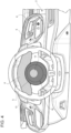
figure 4 is a front view of the passenger compartment with the steering wheel in the lit condition offigure 3 , and -
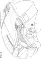
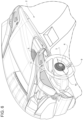
figures 5 - 11 show variants of the passenger compartment of the motor vehicle. - In
figure 1 , reference number 1 is used to indicate, as a whole, a motor vehicle. - The motor vehicle 1 has a
passenger compartment 2 shown infigure 2 . Thepassenger compartment 2 is provided with asteering wheel 3 and with acontrol panel 4, both part of the motor vehicle 1. - Furthermore, the motor vehicle 1 comprises a start or activation device 5 (schematically shown as a logic block in the drawings) operable to cause the motor vehicle 1 to switch to an activation state.
- In the activation state, the motor vehicle 1 becomes responsive to one or more specific commands of a driver, such as, for example, a start command for a powertrain of the motor vehicle 1.
- The powertrain specifically comprises an electric motor. As a matter of fact, in particular, the motor vehicle 1 is a full electric vehicle, even though this is not necessarily the case.
- Other possible specific commands could be, for example, a command for turning on the lights, a command for moving the rear-view mirrors, a command for unlocking the
steering wheel 3 and the like, without losing generality. Generally speaking, the actual type of commands to which the motor vehicle 1 becomes responsive in the activation state is not strictly essential. - The activation state preferably corresponds to a state of authorization to the starting of the motor vehicle 1. In other words, without the authorization state imparted by means of the
activation device 5, the motor vehicle 1 cannot start. Namely, the authorization state is an essential condition, even though not the only essential condition, to allow the motor vehicle 1 to start. - When the motor vehicle 1 is not in the activation state, the motor vehicle 1 is in a deactivation state, in which the motor vehicle 1 does not respond to the specific commands mentioned above. However, this does not mean that the motor vehicle 1 necessarily is not responsive to any type of command. On the contrary, in the deactivation state, the motor vehicle 1 could optionally respond to other commands, such as a command for activating the emergency brake, a command for opening a hood, a command for moving the windows, a command for turning on an anti-theft system and the like, without losing generality.
- More in detail, the
activation device 5 is operable by the driver by means of asuitable control 6, for example comprising a button, in particular located at a dashboard of the motor vehicle 1. Thecontrol 6 could comprise, as an alternative or in addition, a vocal or tactile control (for instance, a fingerprint recognizer) or an optical control (for example, a face recognizer). Alternatively or in addition, thecontrol 6 could further comprise a lever, a knob and the like. - The
control 6 preferably works, i.e. operates theactivation device 5 in order to cause the motor vehicle 1 to switch to the activation state, subject to a condition, for example defined by a detection of a key or of the presence thereof inside thepassenger compartment 2 by means of a key detector device of the motor vehicle 1. - The
control 6 could even be absent, whereby thedevice 5 would automatically work so as to cause the motor vehicle 1 to switch to the activation state, for example when the condition occurs or when the presence of the driver in thepassenger compartment 2 is detected by a suitable detector or when a door of the motor vehicle 1 is opened to allow the driver to access thepassenger compartment 2. - The key, when present, could be any kind of key, if necessary even a non-physical, namely virtual key. For instance, the key could be replaced by a password or by a vocal command or by a fingerprint or the like.
- The key could comprise a traditional key, i.e. a key with a physical member than can be inserted into a suitable seat or ignition switch and then rotated in a clockwise or counterclockwise direction in the ignition key in order to fulfil the aforesaid condition.
- Alternatively, the key could comprise a computerreadable means, for instance a USB flash drive.
- In other words, the
control 6 can be used to cause the motor vehicle 1 to switch to the activation state, like it usually happens, in general, in some known motor vehicles. - Alternatively, the
control 6 can be replaced by the key or comprise the key. In this case, the key is inserted into the ignition switch or, more in general, into a seat thereof and possibly, though not necessarily, rotated or moved in the seat in order to cause the motor vehicle 1 to switch to the activation state. - Therefore, the activation state is the state commonly known as key-on state.
- For example, according to the variant of
figures 5 ,6 , thecontrol 6 is replaced by the key, in particular having a physical member. In this variant, thedevice 5 comprises aseat 7 for thekey 6. Theseat 7 is obtained, in particular, on thesteering wheel 3, even though this is not necessary. As a matter of fact, theseat 7 could also be obtained in the tunnel, on the dashboard or somewhere else. - Furthermore, in this variant, the
activation device 5 causes the motor vehicle 1 to switch to the activation state when theseat 7 receives the physical member of thekey 6. - More in detail, the
activation device 5 comprises a detector of the presence of the physical member of thekey 6 in theseat 7. In this way, theactivation device 5 causes the motor vehicle 1 to switch to the activation state when the detector detects the presence of the physical member of thekey 6 in theseat 7. - The detector can work in different ways; the actual way in which the presence of the physical member is detected is not essential. For example, the detector can have a magnetic or optical operation or it can recognize the physical member through RFID devices or other known devices for key identification.
- On the other hand, in the other variants, the
device 5 causes the motor vehicle 1 to switch to the activation state when thecontrol 6 is operated, specifically pressed, and preferably when the aforesaid condition is fulfilled, i.e. subject to the fulfilment of the condition. - According to the invention, the
steering wheel 3 comprises atransparent portion 10 and alight emission device 11 configured to light thetransparent portion 10 when the motor vehicle switches to the activation state by means of theactivation device 5. - In this way, the light emitted by the
light emission device 11 is transmitted through thetransparent portion 10, so as to be visible to the driver. - Hence, the driver perceives that the
transparent portion 10 is lit during the activation state of the motor vehicle 1. - The
light emission device 11 is configured to light thetransparent portion 10 as soon as (or in the moment in which) the activation state occurs (figure 3 ). - Therefore, the
transparent portion 10 is lit by thelight emission device 11 only when the activation state occurs. In other words, thelight emission device 11 is configured to light the transparent portion only when the activation state occurs. - The
light emission device 11 can be of a known kind and, therefore, is only schematically shown. Thelight emission device 11 can be located behind thetransport portion 10, for example so that thetransparent portion 10 serves as a screen of thelight emission device 11. - For instance, the
light emission device 11 could comprise a LED matrix behind thetransparent portion 10. Furthermore, thelight emission device 11 could comprise one or more light filters, possibly coloured ones, between the LED matrix and thetransparent portion 10. - Based on the above, the
transparent portion 10 could be considered as an integral part of thelight emission device 11. - In particular, the
transparent portion 10 and/or thelight emission device 11 are designed to break in a controlled manner in response to a predetermined load, for example a load corresponding to the activation of the airbag module. Furthermore, thetransparent portion 10 and/or thelight emission device 11 are designed, for example thanks to a suitable selection of the materials, shapes and dimensions, so as not to be harmful to the user in front of thesteering wheel 3. - Preferably, as shown in
figure 3 , thecontrol panel 4 also lights up when or as soon as the activation state occurs. - To be clear, the term "transparent" should be understood as having a certain degree of transparency, which can be equal to or smaller than 1000, though not zero. In other words, the
portion 10 is not completely opaque or reflecting, i.e. it allows light to be transmitted through it. - The
portion 10 preferably is translucent, namely it allows light to be transmitted through it, but it does not allow the driver to clearly see what is behind theportion 10, in particular when thelight emission device 11 is turned off, i.e. does not emit light or does not light theportion 10. - The
portion 10 conveniently is part of an outer cover of an airbag module or consists of the outer cover. - The airbag module for the
steering wheel 3 has a commonly known function and consists of known components except for the outer cover, since the latter comprises thetransparent portion 10 and, for this reason, is novel relative to the state of the art. Therefore, the soletransparent portion 10 will be described in detail below. - Specifically, the
portion 10 is centrally arranged on thesteering wheel 3, namely it is arranged at the centre of thesteering wheel 3. - The
portion 10 comprises acap 9 with a spheroidal shape. In other words, theportion 10 comprises a ball- or globeshaped element, basically similar to an eyeball. - The
cap 9 has, in particular, a pole at the centre of thesteering wheel 3. For example, the pole could be part of a flattened surface relative to the rest of thecap 9 or even of a flat surface of thecap 9. - In the embodiment of
figure 3 , thecap 9 has twodistinct zones light emission device 11. - In particular, the light transmitted by the
zones - More in particular, the colour of the lit
zone 12 is lighter than the one of the litzone 13. - Alternatively or in addition, the lit
zone 12 has a greater brightness or brilliance than the litzone 13. - However, this is not necessarily the case, since the contrary can also apply to the
zones - The effect perceived by the driver can be obtained in other ways.
- For example, the
zones light emission device 11. - Alternatively, according to another example, the
light emission device 11 could be directly configured to light thezones zones - These last two examples could even be combined with one another.
- In other words, the
light emission device 11 and/or thezones zones zones - For example, as mentioned above, the driver could perceive the
zones zones light emission device 11 lights theportion 10 and, consequently, thecap 9 with itszones - In the embodiment shown herein, the
zone 12 is polar, namely it includes the pole of thecap 9 and is a spheroidal cap itself. - The
zone 13 can be obtained as a subtraction of thezone 12 from thecap 9; hence, thezone 13 defines, in particular, a spheroid segment between two planes that are secant, more in particular orthogonal to an axis of thecap 9 going through the pole. - Furthermore, the spheroid segment defined by the
zone 13 constitutes a base for the spheroid segment defined by thezone 12. Thezones cap 9 going through the pole. - In practical terms, following an analogy with an eyeball, the
zone 12 would be the iris, whereas thezone 13 would be pupil. - According to the variant of
figures 9 - 11 , thezone 12 comprises an indicator, specifically a speedometer, to provide the driver with driving information. In particular, the indicator is illuminable and provides the driving information only when it is illuminated. Since thearea 12 is lit when the motor vehicle 1 is caused to switch to the activation state through theactivation device 5, the indicator provides the information only when the motor vehicle 1 is in the activation state. - According to the variant of
figures 7 ,8 , thezone 12 can rotate around a rotation axis of thesteering wheel 3 or around the axis of thecap 9 relative to thezone 13. In this variant, the motor vehicle 1 comprises an actuator device not shown herein and configured to rotate thezone 13 from a first position to a second position, when the motor vehicle is caused to switch to the activation state through theactivation device 5. Thezone 12 preferably includes an indicator, for example a pointer, which cooperates with another indicator of thezone 13, when thezone 12 is in the second position, to indicate the activation state to the driver. - Owing to the above, the advantages of the motor vehicle 1 according to the invention are evident.
- The driver has an ideal perception of the activation state, since the
steering wheel 3 lights up through thetransparent portion 10 and thelight emission device 11. - In particular, the light emitted by the
light emission device 11 and transmitted through thetransparent portion 10 directly enters the primary visibility cone of the driver, thus stimulating his/her attention in an improved manner compared to the prior art. - The shape and the arrangement of the
transparent portion 10 further help improve the driver's perception of the activation state of the motor vehicle 1. - Finally, the motor vehicle 1 according to the invention can be subjected to changes and variants, which, though, do not go beyond the scope of protection set forth in the appended claims.
Claims (10)
- A motor vehicle (1) comprising a steering wheel (3) and an activation device (5) operable to cause the motor vehicle (1) to switch to an activation state, in which the motor vehicle (1) becomes responsive to one or more specific commands of a driver,
characterized in that the steering wheel (3) comprises a transparent portion (10) and a light emission device (11) configured to light the transparent portion (10) when the motor vehicle switches to the activation state by means of the activation device (5). - The motor vehicle according to claim 1, wherein the steering wheel (3) comprises an airbag module having an outer cover comprising said transparent portion (10).
- The motor vehicle according to claim 1 or 2, wherein the transparent portion (10) is arranged at the centre of the steering wheel (3).
- The motor vehicle according to any one of the preceding claims, wherein the transparent portion (10) comprises a spheroidal cap (9).
- The motor vehicle according to claim 4, wherein the spheroidal cap (9) has a pole at the centre of the steering wheel (3).
- The motor vehicle according to claim 4 or 5, wherein the spheroidal cap (9) comprises a first zone (12) and a second zone (13) respectively transmitting light with distinct properties, for example with distinct colours, when they are lit by means of the light emission device (11).
- The motor vehicle according to claim 6, wherein the first zone (12) is polar and, in turn, is defined by a further spheroidal cap.
- The motor vehicle according to claim 6 or 7, wherein the first zone (12) has a greater brightness than the second zone (13), when the first and the second zone (12, 13) are lit by means of the light emission device (11).
- The motor vehicle according to any one of the preceding claims, wherein said one or more specific commands include a command to turn on a motor of the motor vehicle (1) .
- The motor vehicle according to any one of the preceding claims, wherein the activation device (5) is operable by the driver by means of a command (6).
Applications Claiming Priority (1)
| Application Number | Priority Date | Filing Date | Title |
|---|---|---|---|
| IT102022000022698A IT202200022698A1 (en) | 2022-11-04 | 2022-11-04 | MOTOR VEHICLE WITH A STEERING WHEEL EQUIPPED WITH AN ILLUMINABLE PORTION |
Publications (1)
| Publication Number | Publication Date |
|---|---|
| EP4364999A1 true EP4364999A1 (en) | 2024-05-08 |
Family
ID=84943065
Family Applications (1)
| Application Number | Title | Priority Date | Filing Date |
|---|---|---|---|
| EP23206049.1A Pending EP4364999A1 (en) | 2022-11-04 | 2023-10-26 | Motor vehicle with steering wheel provided with an illuminable portion |
Country Status (3)
| Country | Link |
|---|---|
| US (1) | US12337753B2 (en) |
| EP (1) | EP4364999A1 (en) |
| IT (1) | IT202200022698A1 (en) |
Families Citing this family (1)
| Publication number | Priority date | Publication date | Assignee | Title |
|---|---|---|---|---|
| JP1764099S (en) * | 2023-06-05 | 2024-02-21 | vehicle dashboard |
Citations (3)
| Publication number | Priority date | Publication date | Assignee | Title |
|---|---|---|---|---|
| US20090121459A1 (en) * | 2007-11-09 | 2009-05-14 | Tk Holdings Inc. | Lighted airbag module |
| US20150375678A1 (en) * | 2013-11-21 | 2015-12-31 | Ford Global Technologies, Llc | Illuminated steering assembly |
| DE102019103752A1 (en) * | 2019-02-14 | 2020-08-20 | Trw Automotive Safety Systems Gmbh | Steering device, gas bag module for this steering device and method for triggering a horn signal in such a steering device |
Family Cites Families (7)
| Publication number | Priority date | Publication date | Assignee | Title |
|---|---|---|---|---|
| WO2013183144A1 (en) * | 2012-06-07 | 2013-12-12 | パイオニア株式会社 | Light emitting unit for vehicle |
| US9481297B2 (en) * | 2013-11-21 | 2016-11-01 | Ford Global Technologies, Llc | Illuminated steering assembly |
| US9873446B2 (en) * | 2014-07-23 | 2018-01-23 | Tk Holdings, Inc. | Steering grip light bar systems |
| DE102017100005A1 (en) * | 2017-01-02 | 2018-07-05 | Volkswagen Aktiengesellschaft | METHOD FOR STEERING A VEHICLE WITH AN AUTOMATIC OPERATION MODE AND VEHICLE WITH AN AUTOMATIC OPERATION MODE |
| EP4191204A4 (en) * | 2020-07-30 | 2024-11-06 | LG Electronics Inc. | Route guidance device and route guidance method thereof |
| IT202200022626A1 (en) * | 2022-11-04 | 2024-05-04 | Ferrari Spa | LIGHTED GEAR LEVER FOR STARTING A ROAD VEHICLE AND RELATED ROAD VEHICLE |
| WO2024233840A1 (en) * | 2023-05-10 | 2024-11-14 | Apple Inc. | User interfaces with dynamic display of map information |
-
2022
- 2022-11-04 IT IT102022000022698A patent/IT202200022698A1/en unknown
-
2023
- 2023-10-26 EP EP23206049.1A patent/EP4364999A1/en active Pending
- 2023-10-31 US US18/498,569 patent/US12337753B2/en active Active
Patent Citations (3)
| Publication number | Priority date | Publication date | Assignee | Title |
|---|---|---|---|---|
| US20090121459A1 (en) * | 2007-11-09 | 2009-05-14 | Tk Holdings Inc. | Lighted airbag module |
| US20150375678A1 (en) * | 2013-11-21 | 2015-12-31 | Ford Global Technologies, Llc | Illuminated steering assembly |
| DE102019103752A1 (en) * | 2019-02-14 | 2020-08-20 | Trw Automotive Safety Systems Gmbh | Steering device, gas bag module for this steering device and method for triggering a horn signal in such a steering device |
Also Published As
| Publication number | Publication date |
|---|---|
| US20240149786A1 (en) | 2024-05-09 |
| US12337753B2 (en) | 2025-06-24 |
| IT202200022698A1 (en) | 2024-05-04 |
Similar Documents
| Publication | Publication Date | Title |
|---|---|---|
| US11794579B2 (en) | Driving system for automated driving with a steering wheel display | |
| JP6750523B2 (en) | In-vehicle device | |
| US9087417B2 (en) | Window device with lighting for a motor vehicle | |
| US20180143754A1 (en) | Vehicle steering and control device (vscd) | |
| US9751461B2 (en) | Device for displaying at least one pictogram inside a vehicle passenger compartment | |
| KR101351656B1 (en) | Vehicular glance lighting apparatus | |
| WO2009027565A1 (en) | System of early warning of the opening of an automobile vehicle door | |
| US20200055397A1 (en) | User interface and method for the input and output of information in a vehicle | |
| EP4364999A1 (en) | Motor vehicle with steering wheel provided with an illuminable portion | |
| JP5588764B2 (en) | In-vehicle device operation device | |
| EP4385820B1 (en) | Lighting device and method for vehicle | |
| US12280714B2 (en) | Input device | |
| JPH05221263A (en) | Display device for vehicle | |
| JP2005119651A (en) | Device for status information on vehicle components | |
| JP2021066228A (en) | Vehicle body behavior notifying device | |
| JP4498112B2 (en) | Vehicle switch | |
| JP3203807U (en) | Device for preventing mistakes in pedaling for automobiles | |
| IT202200022704A1 (en) | MOTOR VEHICLE WITH A STEERING WHEEL EQUIPPED WITH A DISPLAY | |
| US20240149831A1 (en) | Biometrical device for turning on a road vehicle and relative road vehicle | |
| US20240149897A1 (en) | Gesture device for turning on a road vehicle and relative road vehicle | |
| US12559122B2 (en) | Steering input with light source | |
| GB2330435A (en) | Drivers safety alarm | |
| JP4526353B2 (en) | Starter switch | |
| JP4074125B2 (en) | Vehicle start switch display control device | |
| IT202200022710A1 (en) | MOTOR VEHICLE WITH A STEERING WHEEL PROVIDED WITH A PORTION THAT ROTATES WITH RESPECT TO THE REST OF THE STEERING WHEEL |
Legal Events
| Date | Code | Title | Description |
|---|---|---|---|
| PUAI | Public reference made under article 153(3) epc to a published international application that has entered the european phase |
Free format text: ORIGINAL CODE: 0009012 |
|
| STAA | Information on the status of an ep patent application or granted ep patent |
Free format text: STATUS: THE APPLICATION HAS BEEN PUBLISHED |
|
| AK | Designated contracting states |
Kind code of ref document: A1 Designated state(s): AL AT BE BG CH CY CZ DE DK EE ES FI FR GB GR HR HU IE IS IT LI LT LU LV MC ME MK MT NL NO PL PT RO RS SE SI SK SM TR |
|
| STAA | Information on the status of an ep patent application or granted ep patent |
Free format text: STATUS: REQUEST FOR EXAMINATION WAS MADE |
|
| 17P | Request for examination filed |
Effective date: 20241106 |
|
| RBV | Designated contracting states (corrected) |
Designated state(s): AL AT BE BG CH CY CZ DE DK EE ES FI FR GB GR HR HU IE IS IT LI LT LU LV MC ME MK MT NL NO PL PT RO RS SE SI SK SM TR |