EP4364993A1 - Display for vehicle including a plastic cover lens - Google Patents
Display for vehicle including a plastic cover lens Download PDFInfo
- Publication number
- EP4364993A1 EP4364993A1 EP23170394.3A EP23170394A EP4364993A1 EP 4364993 A1 EP4364993 A1 EP 4364993A1 EP 23170394 A EP23170394 A EP 23170394A EP 4364993 A1 EP4364993 A1 EP 4364993A1
- Authority
- EP
- European Patent Office
- Prior art keywords
- plastic cover
- cover lens
- lens
- display
- curvature
- Prior art date
- Legal status (The legal status is an assumption and is not a legal conclusion. Google has not performed a legal analysis and makes no representation as to the accuracy of the status listed.)
- Granted
Links
Images

Classifications
-
- G—PHYSICS
- G02—OPTICS
- G02F—OPTICAL DEVICES OR ARRANGEMENTS FOR THE CONTROL OF LIGHT BY MODIFICATION OF THE OPTICAL PROPERTIES OF THE MEDIA OF THE ELEMENTS INVOLVED THEREIN; NON-LINEAR OPTICS; FREQUENCY-CHANGING OF LIGHT; OPTICAL LOGIC ELEMENTS; OPTICAL ANALOGUE/DIGITAL CONVERTERS
- G02F1/00—Devices or arrangements for the control of the intensity, colour, phase, polarisation or direction of light arriving from an independent light source, e.g. switching, gating or modulating; Non-linear optics
- G02F1/01—Devices or arrangements for the control of the intensity, colour, phase, polarisation or direction of light arriving from an independent light source, e.g. switching, gating or modulating; Non-linear optics for the control of the intensity, phase, polarisation or colour
- G02F1/13—Devices or arrangements for the control of the intensity, colour, phase, polarisation or direction of light arriving from an independent light source, e.g. switching, gating or modulating; Non-linear optics for the control of the intensity, phase, polarisation or colour based on liquid crystals, e.g. single liquid crystal display cells
- G02F1/133—Constructional arrangements; Operation of liquid crystal cells; Circuit arrangements
- G02F1/1333—Constructional arrangements; Manufacturing methods
- G02F1/1335—Structural association of cells with optical devices, e.g. polarisers or reflectors
- G02F1/133509—Filters, e.g. light shielding masks
- G02F1/133512—Light shielding layers, e.g. black matrix
-
- B—PERFORMING OPERATIONS; TRANSPORTING
- B60—VEHICLES IN GENERAL
- B60K—ARRANGEMENT OR MOUNTING OF PROPULSION UNITS OR OF TRANSMISSIONS IN VEHICLES; ARRANGEMENT OR MOUNTING OF PLURAL DIVERSE PRIME-MOVERS IN VEHICLES; AUXILIARY DRIVES FOR VEHICLES; INSTRUMENTATION OR DASHBOARDS FOR VEHICLES; ARRANGEMENTS IN CONNECTION WITH COOLING, AIR INTAKE, GAS EXHAUST OR FUEL SUPPLY OF PROPULSION UNITS IN VEHICLES
- B60K35/00—Instruments specially adapted for vehicles; Arrangement of instruments in or on vehicles
-
- B—PERFORMING OPERATIONS; TRANSPORTING
- B60—VEHICLES IN GENERAL
- B60K—ARRANGEMENT OR MOUNTING OF PROPULSION UNITS OR OF TRANSMISSIONS IN VEHICLES; ARRANGEMENT OR MOUNTING OF PLURAL DIVERSE PRIME-MOVERS IN VEHICLES; AUXILIARY DRIVES FOR VEHICLES; INSTRUMENTATION OR DASHBOARDS FOR VEHICLES; ARRANGEMENTS IN CONNECTION WITH COOLING, AIR INTAKE, GAS EXHAUST OR FUEL SUPPLY OF PROPULSION UNITS IN VEHICLES
- B60K35/00—Instruments specially adapted for vehicles; Arrangement of instruments in or on vehicles
- B60K35/50—Instruments characterised by their means of attachment to or integration in the vehicle
-
- B—PERFORMING OPERATIONS; TRANSPORTING
- B29—WORKING OF PLASTICS; WORKING OF SUBSTANCES IN A PLASTIC STATE IN GENERAL
- B29C—SHAPING OR JOINING OF PLASTICS; SHAPING OF MATERIAL IN A PLASTIC STATE, NOT OTHERWISE PROVIDED FOR; AFTER-TREATMENT OF THE SHAPED PRODUCTS, e.g. REPAIRING
- B29C45/00—Injection moulding, i.e. forcing the required volume of moulding material through a nozzle into a closed mould; Apparatus therefor
- B29C45/14—Injection moulding, i.e. forcing the required volume of moulding material through a nozzle into a closed mould; Apparatus therefor incorporating preformed parts or layers, e.g. injection moulding around inserts or for coating articles
- B29C45/14467—Joining articles or parts of a single article
-
- B—PERFORMING OPERATIONS; TRANSPORTING
- B60—VEHICLES IN GENERAL
- B60K—ARRANGEMENT OR MOUNTING OF PROPULSION UNITS OR OF TRANSMISSIONS IN VEHICLES; ARRANGEMENT OR MOUNTING OF PLURAL DIVERSE PRIME-MOVERS IN VEHICLES; AUXILIARY DRIVES FOR VEHICLES; INSTRUMENTATION OR DASHBOARDS FOR VEHICLES; ARRANGEMENTS IN CONNECTION WITH COOLING, AIR INTAKE, GAS EXHAUST OR FUEL SUPPLY OF PROPULSION UNITS IN VEHICLES
- B60K35/00—Instruments specially adapted for vehicles; Arrangement of instruments in or on vehicles
- B60K35/20—Output arrangements, i.e. from vehicle to user, associated with vehicle functions or specially adapted therefor
- B60K35/21—Output arrangements, i.e. from vehicle to user, associated with vehicle functions or specially adapted therefor using visual output, e.g. blinking lights or matrix displays
- B60K35/22—Display screens
-
- B—PERFORMING OPERATIONS; TRANSPORTING
- B60—VEHICLES IN GENERAL
- B60K—ARRANGEMENT OR MOUNTING OF PROPULSION UNITS OR OF TRANSMISSIONS IN VEHICLES; ARRANGEMENT OR MOUNTING OF PLURAL DIVERSE PRIME-MOVERS IN VEHICLES; AUXILIARY DRIVES FOR VEHICLES; INSTRUMENTATION OR DASHBOARDS FOR VEHICLES; ARRANGEMENTS IN CONNECTION WITH COOLING, AIR INTAKE, GAS EXHAUST OR FUEL SUPPLY OF PROPULSION UNITS IN VEHICLES
- B60K35/00—Instruments specially adapted for vehicles; Arrangement of instruments in or on vehicles
- B60K35/40—Instruments specially adapted for improving the visibility thereof to the user, e.g. fogging prevention or anti-reflection arrangements
- B60K35/425—Anti-reflection arrangements
-
- G—PHYSICS
- G02—OPTICS
- G02B—OPTICAL ELEMENTS, SYSTEMS OR APPARATUS
- G02B1/00—Optical elements characterised by the material of which they are made; Optical coatings for optical elements
- G02B1/10—Optical coatings produced by application to, or surface treatment of, optical elements
- G02B1/14—Protective coatings, e.g. hard coatings
-
- G—PHYSICS
- G02—OPTICS
- G02B—OPTICAL ELEMENTS, SYSTEMS OR APPARATUS
- G02B3/00—Simple or compound lenses
-
- G—PHYSICS
- G02—OPTICS
- G02F—OPTICAL DEVICES OR ARRANGEMENTS FOR THE CONTROL OF LIGHT BY MODIFICATION OF THE OPTICAL PROPERTIES OF THE MEDIA OF THE ELEMENTS INVOLVED THEREIN; NON-LINEAR OPTICS; FREQUENCY-CHANGING OF LIGHT; OPTICAL LOGIC ELEMENTS; OPTICAL ANALOGUE/DIGITAL CONVERTERS
- G02F1/00—Devices or arrangements for the control of the intensity, colour, phase, polarisation or direction of light arriving from an independent light source, e.g. switching, gating or modulating; Non-linear optics
- G02F1/01—Devices or arrangements for the control of the intensity, colour, phase, polarisation or direction of light arriving from an independent light source, e.g. switching, gating or modulating; Non-linear optics for the control of the intensity, phase, polarisation or colour
- G02F1/13—Devices or arrangements for the control of the intensity, colour, phase, polarisation or direction of light arriving from an independent light source, e.g. switching, gating or modulating; Non-linear optics for the control of the intensity, phase, polarisation or colour based on liquid crystals, e.g. single liquid crystal display cells
- G02F1/133—Constructional arrangements; Operation of liquid crystal cells; Circuit arrangements
- G02F1/1333—Constructional arrangements; Manufacturing methods
- G02F1/133308—Support structures for LCD panels, e.g. frames or bezels
- G02F1/133331—Cover glasses
-
- G—PHYSICS
- G02—OPTICS
- G02F—OPTICAL DEVICES OR ARRANGEMENTS FOR THE CONTROL OF LIGHT BY MODIFICATION OF THE OPTICAL PROPERTIES OF THE MEDIA OF THE ELEMENTS INVOLVED THEREIN; NON-LINEAR OPTICS; FREQUENCY-CHANGING OF LIGHT; OPTICAL LOGIC ELEMENTS; OPTICAL ANALOGUE/DIGITAL CONVERTERS
- G02F1/00—Devices or arrangements for the control of the intensity, colour, phase, polarisation or direction of light arriving from an independent light source, e.g. switching, gating or modulating; Non-linear optics
- G02F1/01—Devices or arrangements for the control of the intensity, colour, phase, polarisation or direction of light arriving from an independent light source, e.g. switching, gating or modulating; Non-linear optics for the control of the intensity, phase, polarisation or colour
- G02F1/13—Devices or arrangements for the control of the intensity, colour, phase, polarisation or direction of light arriving from an independent light source, e.g. switching, gating or modulating; Non-linear optics for the control of the intensity, phase, polarisation or colour based on liquid crystals, e.g. single liquid crystal display cells
- G02F1/133—Constructional arrangements; Operation of liquid crystal cells; Circuit arrangements
- G02F1/1333—Constructional arrangements; Manufacturing methods
- G02F1/1335—Structural association of cells with optical devices, e.g. polarisers or reflectors
-
- G—PHYSICS
- G02—OPTICS
- G02F—OPTICAL DEVICES OR ARRANGEMENTS FOR THE CONTROL OF LIGHT BY MODIFICATION OF THE OPTICAL PROPERTIES OF THE MEDIA OF THE ELEMENTS INVOLVED THEREIN; NON-LINEAR OPTICS; FREQUENCY-CHANGING OF LIGHT; OPTICAL LOGIC ELEMENTS; OPTICAL ANALOGUE/DIGITAL CONVERTERS
- G02F1/00—Devices or arrangements for the control of the intensity, colour, phase, polarisation or direction of light arriving from an independent light source, e.g. switching, gating or modulating; Non-linear optics
- G02F1/01—Devices or arrangements for the control of the intensity, colour, phase, polarisation or direction of light arriving from an independent light source, e.g. switching, gating or modulating; Non-linear optics for the control of the intensity, phase, polarisation or colour
- G02F1/13—Devices or arrangements for the control of the intensity, colour, phase, polarisation or direction of light arriving from an independent light source, e.g. switching, gating or modulating; Non-linear optics for the control of the intensity, phase, polarisation or colour based on liquid crystals, e.g. single liquid crystal display cells
- G02F1/133—Constructional arrangements; Operation of liquid crystal cells; Circuit arrangements
- G02F1/1333—Constructional arrangements; Manufacturing methods
- G02F1/1335—Structural association of cells with optical devices, e.g. polarisers or reflectors
- G02F1/133526—Lenses, e.g. microlenses or Fresnel lenses
-
- G—PHYSICS
- G09—EDUCATION; CRYPTOGRAPHY; DISPLAY; ADVERTISING; SEALS
- G09F—DISPLAYING; ADVERTISING; SIGNS; LABELS OR NAME-PLATES; SEALS
- G09F9/00—Indicating arrangements for variable information in which the information is built-up on a support by selection or combination of individual elements
- G09F9/30—Indicating arrangements for variable information in which the information is built-up on a support by selection or combination of individual elements in which the desired character or characters are formed by combining individual elements
- G09F9/35—Indicating arrangements for variable information in which the information is built-up on a support by selection or combination of individual elements in which the desired character or characters are formed by combining individual elements being liquid crystals
-
- B—PERFORMING OPERATIONS; TRANSPORTING
- B29—WORKING OF PLASTICS; WORKING OF SUBSTANCES IN A PLASTIC STATE IN GENERAL
- B29C—SHAPING OR JOINING OF PLASTICS; SHAPING OF MATERIAL IN A PLASTIC STATE, NOT OTHERWISE PROVIDED FOR; AFTER-TREATMENT OF THE SHAPED PRODUCTS, e.g. REPAIRING
- B29C45/00—Injection moulding, i.e. forcing the required volume of moulding material through a nozzle into a closed mould; Apparatus therefor
- B29C45/14—Injection moulding, i.e. forcing the required volume of moulding material through a nozzle into a closed mould; Apparatus therefor incorporating preformed parts or layers, e.g. injection moulding around inserts or for coating articles
- B29C45/14467—Joining articles or parts of a single article
- B29C2045/14532—Joining articles or parts of a single article injecting between two sheets
-
- B—PERFORMING OPERATIONS; TRANSPORTING
- B29—WORKING OF PLASTICS; WORKING OF SUBSTANCES IN A PLASTIC STATE IN GENERAL
- B29C—SHAPING OR JOINING OF PLASTICS; SHAPING OF MATERIAL IN A PLASTIC STATE, NOT OTHERWISE PROVIDED FOR; AFTER-TREATMENT OF THE SHAPED PRODUCTS, e.g. REPAIRING
- B29C45/00—Injection moulding, i.e. forcing the required volume of moulding material through a nozzle into a closed mould; Apparatus therefor
- B29C45/14—Injection moulding, i.e. forcing the required volume of moulding material through a nozzle into a closed mould; Apparatus therefor incorporating preformed parts or layers, e.g. injection moulding around inserts or for coating articles
- B29C2045/1486—Details, accessories and auxiliary operations
- B29C2045/14901—Coating a sheet-like insert smaller than the dimensions of the adjacent mould wall
- B29C2045/14918—Coating a sheet-like insert smaller than the dimensions of the adjacent mould wall in-mould-labelling
-
- B—PERFORMING OPERATIONS; TRANSPORTING
- B29—WORKING OF PLASTICS; WORKING OF SUBSTANCES IN A PLASTIC STATE IN GENERAL
- B29C—SHAPING OR JOINING OF PLASTICS; SHAPING OF MATERIAL IN A PLASTIC STATE, NOT OTHERWISE PROVIDED FOR; AFTER-TREATMENT OF THE SHAPED PRODUCTS, e.g. REPAIRING
- B29C45/00—Injection moulding, i.e. forcing the required volume of moulding material through a nozzle into a closed mould; Apparatus therefor
- B29C45/14—Injection moulding, i.e. forcing the required volume of moulding material through a nozzle into a closed mould; Apparatus therefor incorporating preformed parts or layers, e.g. injection moulding around inserts or for coating articles
- B29C2045/1486—Details, accessories and auxiliary operations
- B29C2045/14901—Coating a sheet-like insert smaller than the dimensions of the adjacent mould wall
- B29C2045/14918—Coating a sheet-like insert smaller than the dimensions of the adjacent mould wall in-mould-labelling
- B29C2045/14926—Coating a sheet-like insert smaller than the dimensions of the adjacent mould wall in-mould-labelling multiple labels in the same cavity
-
- B—PERFORMING OPERATIONS; TRANSPORTING
- B29—WORKING OF PLASTICS; WORKING OF SUBSTANCES IN A PLASTIC STATE IN GENERAL
- B29C—SHAPING OR JOINING OF PLASTICS; SHAPING OF MATERIAL IN A PLASTIC STATE, NOT OTHERWISE PROVIDED FOR; AFTER-TREATMENT OF THE SHAPED PRODUCTS, e.g. REPAIRING
- B29C45/00—Injection moulding, i.e. forcing the required volume of moulding material through a nozzle into a closed mould; Apparatus therefor
- B29C45/17—Component parts, details or accessories; Auxiliary operations
- B29C45/46—Means for plasticising or homogenising the moulding material or forcing it into the mould
- B29C45/56—Means for plasticising or homogenising the moulding material or forcing it into the mould using mould parts movable during or after injection, e.g. injection-compression moulding
- B29C45/561—Injection-compression moulding
-
- B—PERFORMING OPERATIONS; TRANSPORTING
- B60—VEHICLES IN GENERAL
- B60K—ARRANGEMENT OR MOUNTING OF PROPULSION UNITS OR OF TRANSMISSIONS IN VEHICLES; ARRANGEMENT OR MOUNTING OF PLURAL DIVERSE PRIME-MOVERS IN VEHICLES; AUXILIARY DRIVES FOR VEHICLES; INSTRUMENTATION OR DASHBOARDS FOR VEHICLES; ARRANGEMENTS IN CONNECTION WITH COOLING, AIR INTAKE, GAS EXHAUST OR FUEL SUPPLY OF PROPULSION UNITS IN VEHICLES
- B60K2360/00—Indexing scheme associated with groups B60K35/00 or B60K37/00 relating to details of instruments or dashboards
- B60K2360/60—Structural details of dashboards or instruments
- B60K2360/68—Features of instruments
- B60K2360/688—Frames or decorative parts
-
- B—PERFORMING OPERATIONS; TRANSPORTING
- B60—VEHICLES IN GENERAL
- B60K—ARRANGEMENT OR MOUNTING OF PROPULSION UNITS OR OF TRANSMISSIONS IN VEHICLES; ARRANGEMENT OR MOUNTING OF PLURAL DIVERSE PRIME-MOVERS IN VEHICLES; AUXILIARY DRIVES FOR VEHICLES; INSTRUMENTATION OR DASHBOARDS FOR VEHICLES; ARRANGEMENTS IN CONNECTION WITH COOLING, AIR INTAKE, GAS EXHAUST OR FUEL SUPPLY OF PROPULSION UNITS IN VEHICLES
- B60K2360/00—Indexing scheme associated with groups B60K35/00 or B60K37/00 relating to details of instruments or dashboards
- B60K2360/60—Structural details of dashboards or instruments
- B60K2360/68—Features of instruments
- B60K2360/693—Cover plate features
-
- B—PERFORMING OPERATIONS; TRANSPORTING
- B60—VEHICLES IN GENERAL
- B60K—ARRANGEMENT OR MOUNTING OF PROPULSION UNITS OR OF TRANSMISSIONS IN VEHICLES; ARRANGEMENT OR MOUNTING OF PLURAL DIVERSE PRIME-MOVERS IN VEHICLES; AUXILIARY DRIVES FOR VEHICLES; INSTRUMENTATION OR DASHBOARDS FOR VEHICLES; ARRANGEMENTS IN CONNECTION WITH COOLING, AIR INTAKE, GAS EXHAUST OR FUEL SUPPLY OF PROPULSION UNITS IN VEHICLES
- B60K2360/00—Indexing scheme associated with groups B60K35/00 or B60K37/00 relating to details of instruments or dashboards
- B60K2360/92—Manufacturing of instruments
-
- B—PERFORMING OPERATIONS; TRANSPORTING
- B60—VEHICLES IN GENERAL
- B60K—ARRANGEMENT OR MOUNTING OF PROPULSION UNITS OR OF TRANSMISSIONS IN VEHICLES; ARRANGEMENT OR MOUNTING OF PLURAL DIVERSE PRIME-MOVERS IN VEHICLES; AUXILIARY DRIVES FOR VEHICLES; INSTRUMENTATION OR DASHBOARDS FOR VEHICLES; ARRANGEMENTS IN CONNECTION WITH COOLING, AIR INTAKE, GAS EXHAUST OR FUEL SUPPLY OF PROPULSION UNITS IN VEHICLES
- B60K2360/00—Indexing scheme associated with groups B60K35/00 or B60K37/00 relating to details of instruments or dashboards
- B60K2360/92—Manufacturing of instruments
- B60K2360/96—Manufacturing of instruments by assembling
-
- B—PERFORMING OPERATIONS; TRANSPORTING
- B60—VEHICLES IN GENERAL
- B60Y—INDEXING SCHEME RELATING TO ASPECTS CROSS-CUTTING VEHICLE TECHNOLOGY
- B60Y2400/00—Special features of vehicle units
- B60Y2400/92—Driver displays
-
- G—PHYSICS
- G02—OPTICS
- G02B—OPTICAL ELEMENTS, SYSTEMS OR APPARATUS
- G02B1/00—Optical elements characterised by the material of which they are made; Optical coatings for optical elements
- G02B1/10—Optical coatings produced by application to, or surface treatment of, optical elements
- G02B1/11—Anti-reflection coatings
-
- G—PHYSICS
- G02—OPTICS
- G02B—OPTICAL ELEMENTS, SYSTEMS OR APPARATUS
- G02B1/00—Optical elements characterised by the material of which they are made; Optical coatings for optical elements
- G02B1/10—Optical coatings produced by application to, or surface treatment of, optical elements
- G02B1/18—Coatings for keeping optical surfaces clean, e.g. hydrophobic or photo-catalytic films
-
- G—PHYSICS
- G02—OPTICS
- G02F—OPTICAL DEVICES OR ARRANGEMENTS FOR THE CONTROL OF LIGHT BY MODIFICATION OF THE OPTICAL PROPERTIES OF THE MEDIA OF THE ELEMENTS INVOLVED THEREIN; NON-LINEAR OPTICS; FREQUENCY-CHANGING OF LIGHT; OPTICAL LOGIC ELEMENTS; OPTICAL ANALOGUE/DIGITAL CONVERTERS
- G02F1/00—Devices or arrangements for the control of the intensity, colour, phase, polarisation or direction of light arriving from an independent light source, e.g. switching, gating or modulating; Non-linear optics
- G02F1/01—Devices or arrangements for the control of the intensity, colour, phase, polarisation or direction of light arriving from an independent light source, e.g. switching, gating or modulating; Non-linear optics for the control of the intensity, phase, polarisation or colour
- G02F1/13—Devices or arrangements for the control of the intensity, colour, phase, polarisation or direction of light arriving from an independent light source, e.g. switching, gating or modulating; Non-linear optics for the control of the intensity, phase, polarisation or colour based on liquid crystals, e.g. single liquid crystal display cells
- G02F1/133—Constructional arrangements; Operation of liquid crystal cells; Circuit arrangements
- G02F1/1333—Constructional arrangements; Manufacturing methods
- G02F1/1335—Structural association of cells with optical devices, e.g. polarisers or reflectors
- G02F1/133502—Antiglare, refractive index matching layers
-
- G—PHYSICS
- G02—OPTICS
- G02F—OPTICAL DEVICES OR ARRANGEMENTS FOR THE CONTROL OF LIGHT BY MODIFICATION OF THE OPTICAL PROPERTIES OF THE MEDIA OF THE ELEMENTS INVOLVED THEREIN; NON-LINEAR OPTICS; FREQUENCY-CHANGING OF LIGHT; OPTICAL LOGIC ELEMENTS; OPTICAL ANALOGUE/DIGITAL CONVERTERS
- G02F1/00—Devices or arrangements for the control of the intensity, colour, phase, polarisation or direction of light arriving from an independent light source, e.g. switching, gating or modulating; Non-linear optics
- G02F1/01—Devices or arrangements for the control of the intensity, colour, phase, polarisation or direction of light arriving from an independent light source, e.g. switching, gating or modulating; Non-linear optics for the control of the intensity, phase, polarisation or colour
- G02F1/13—Devices or arrangements for the control of the intensity, colour, phase, polarisation or direction of light arriving from an independent light source, e.g. switching, gating or modulating; Non-linear optics for the control of the intensity, phase, polarisation or colour based on liquid crystals, e.g. single liquid crystal display cells
- G02F1/133—Constructional arrangements; Operation of liquid crystal cells; Circuit arrangements
- G02F1/1333—Constructional arrangements; Manufacturing methods
- G02F1/1337—Surface-induced orientation of the liquid crystal molecules, e.g. by alignment layers
-
- G—PHYSICS
- G02—OPTICS
- G02F—OPTICAL DEVICES OR ARRANGEMENTS FOR THE CONTROL OF LIGHT BY MODIFICATION OF THE OPTICAL PROPERTIES OF THE MEDIA OF THE ELEMENTS INVOLVED THEREIN; NON-LINEAR OPTICS; FREQUENCY-CHANGING OF LIGHT; OPTICAL LOGIC ELEMENTS; OPTICAL ANALOGUE/DIGITAL CONVERTERS
- G02F2202/00—Materials and properties
- G02F2202/28—Adhesive materials or arrangements
Definitions
- the present disclosure relates to a display for a vehicle including a plastic cover lens disposed in a cluster and a center fascia of the vehicle.
- a cluster provides various types of information related to a travel state of a vehicle to a driver as visual information.
- a speed of the vehicle, an engine RPM, a fuel amount, a thermometer, and various warnings are displayed.
- a display installed in a center fascia provides various additional convenient information including a navigation to the driver. As the vehicle becomes smarter, an amount of information provided by the cluster increases.
- one embodiment of the present disclosure is to provide a display for a vehicle that reduces manufacturing costs, provides sufficient durability and optical performance required for the display for the vehicle, and is advantageous for enlargement by applying a plastic cover lens instead of a glass lens as a lens of the display for the vehicle having a three-dimensional shape.
- a display for a vehicle includes a plastic cover lens including a lens, a front film disposed on a front surface of the lens, and a rear film disposed on a rear surface of the lens, a super retardation film (SRF) adhered to a rear surface of the plastic cover lens using an optically clear adhesive (OCA), a liquid crystal display module adhered to a rear surface of the super retardation film using the optically clear adhesive, a panel-front assembled at the rear of the plastic cover lens, in close contact with and supporting the liquid crystal display module, and preventing deformation of the plastic cover lens, and a rear cover assembled at the rear of the panel-front.
- SRF super retardation film
- OCA optically clear adhesive
- the front film includes an anti-reflection (AR) coating layer and an anti-fingerprint (AF) coating layer formed at a front surface of the plastic cover lens via vacuum deposition.
- AR anti-reflection
- AF anti-fingerprint
- the rear film includes a black masking layer printed on the rear surface of the lens excluding a window area corresponding to a position of the liquid crystal display module.
- the plastic cover lens includes the front film and the rear film pre-molded in a shape of the plastic cover lens and is formed via insert mold labeling (IML).
- IML insert mold labeling
- the plastic cover lens is formed such that a residual stress resulted from injection is minimized as the front film is disposed in an upper core of a mold and the rear film is disposed in a lower core of the mold and are pressurized to simultaneously perform injection-compression molding (ICM) during in-mold molding.
- ICM injection-compression molding
- the plastic cover lens includes a first area disposed on a side of a driver, a second area disposed on an opposite side of the first area, and a bent portion disposed between the first area and the second area.
- a first radius of curvature of the plastic cover lens is applied such that a radius of curvature of the bent portion is greater than a radius of curvature of the first area and a radius of curvature of the second area is greater than the radius of curvature of the bent portion.
- the plastic cover lens is formed in a shape having a 3D curvature as the first radius of curvature is applied to the plastic cover lens in a horizontal direction, a second radius of curvature is applied to the plastic cover lens in a vertical direction for the plastic cover lens to become a concave lens, and a third radius of curvature is applied to a corner of the plastic cover lens.
- the corner of the plastic cover lens is formed to be rounded with a radius in a range from 2 mm to 3 mm.
- the display further includes a carrier-bezel mechanically coupled to an edge of the plastic cover lens to firmly maintain a shape of the plastic cover lens.
- the display further includes an adhesive tape adhered to at least a portion of the rear surface of the plastic cover lens to couple the plastic cover lens and the carrier-bezel to each other.
- the three-dimensional shape may be easily implemented by applying the plastic cover lens as the lens for the display for the vehicle.
- the manufacturing costs may be significantly reduced by reducing the gate wash-out caused by the insert mold labeling (IML) scheme via the placement of the black masking layer on the rear surface of the plastic cover lens of the display for the vehicle.
- IML insert mold labeling
- FIG. 1 is an exploded perspective view of a display for a vehicle including a plastic cover lens according to one embodiment of the present disclosure.
- a display 100 for a vehicle including a plastic cover lens may include a plastic cover lens 10, an optical bonding layer 20, a liquid crystal display module 30, a panel-front 40, brackets 51 and 52, and a rear cover 60.
- a console display that displays various convenient information such as a navigation is disposed in a cluster and a center fascia that display a basic state of the vehicle.
- the display 100 for the vehicle includes the plastic cover lens 10 and is disposed across the cluster and the center fascia in front of a driver will be exemplified.
- the plastic cover lens 10 having a plurality of curvatures is disposed on an outermost surface of the display 100 for the vehicle toward the driver, that is, at a front portion of the display 100 for the vehicle.
- the plastic cover lens 10 may include a lens 11, a front film 12 disposed on a front surface of the lens, which is the outermost surface toward the driver, and a rear film 13 disposed on a rear surface of the lens.
- the lens 11 may be manufactured by high fluidity PC clear injection molding.
- the front film 12 including anti-reflection (AR) and anti-fingerprint (AF) coating layers may be disposed on the front surface of the lens 110 by vacuum deposition.
- the front film 12 may be formed to realize hardness and transparency of the plastic cover lens 10.
- the rear film 13 may be disposed on the rear surface of the lens 11, and the rear film may include a black masking layer.
- the black masking layer may be printed except for a window area corresponding to a position of the liquid crystal display (LCD) module.
- the plastic cover lens 10 exhibits an excellent optical property by molding the front film and a second film in a predetermined shape, inserting a first film into an upper core of a mold and inserting the rear film into a lower core of the mold, and performing compression molding during injection.
- the plastic cover lens 10 has an effect of reducing reflection of stray light by applying compression injection to minimize birefringence.
- the plastic cover lens 10 may be formed in an insert mold labeling (IML) scheme.
- IML insert mold labeling
- the front film and the rear film 12 and 13 are molded into a shape of the lens 11 beforehand, then inserted into the mold, and then finally molded with plastic inserted from the rear.
- a hard coated film material may be used, so that a considerable level of abrasion resistance may be secured.
- the different films may be manufactured using the same plastic cover lens mold, a variety of products may be manufactured in small quantities.
- the plastic cover lens 10 may be formed in an injection-compression molding (ICM) scheme.
- ICM injection-compression molding
- the injection-compression molding may be performed along with the insert mold labeling. Therefore, after the molding of the plastic cover lens 10, a density of the plastic cover lens 10 may be maintained more uniformly throughout a body and a residual stress of the injection-molded product resulted from a difference in a cooling speed depending on a shape of the lens and a structure of the mold may be minimized.
- the optical bonding layer 20 may include an optically clear adhesive (OCA) 21 and a super retardation film (SRF) 22.
- OCA optically clear adhesive
- SRF super retardation film
- the optically clear adhesive 21 may be disposed on a rear surface of the plastic cover lens 10 to be optically in contact with a liquid crystal display (LCD).
- the super retardation film 22 may be disposed between the optically clear adhesive 21 and the liquid crystal display (LCD).
- polarization On a front surface of the liquid crystal display, polarization may be applied and utilized in a complex manner to enhance a clarity, a viewing angle, and the like.
- a rainbow-shaped distortion may occur in an image displayed on the liquid crystal display because of the complex polarization states.
- Internal stress in the plastic cover lens 10 causes a phase shift in transmitted light, resulting in increased birefringence and making such distortion more pronounced.
- the super retardation film 22 may be bonded to the rear surface of the plastic cover lens 10 via direct bonding using the optically clear adhesive (OCA) 21. In such manner, the plastic cover lens 10 and the super retardation film 22 may act as one optical element.
- OCA optically clear adhesive
- the liquid crystal display 10 may be bonded a rear surface of the super retardation film 22 using the optically clear adhesive (OCA) such that the liquid crystal display to the plastic cover lens 10 act as one optical element and reflection at a bonding surface is minimized.
- OCA optically clear adhesive
- the optically clear adhesive 21 may be disposed on the rear surface of the super retardation film 22 or on a front surface of the liquid crystal display and the liquid crystal display may be attached to the rear surface of the super retardation film 22 to bond the liquid crystal display to the super retardation film 22.
- the liquid crystal display module 30 may include the liquid crystal display (LCD) and a back light unit (BLU).
- LCD liquid crystal display
- BLU back light unit
- the panel-front 40 is formed to have high structural rigidity and is coupled to the plastic cover lens 10 to maintain a design shape of the plastic cover lens 10. A remaining area of the rear surface of the panel-front 40 except for a pocket area formed to accommodate the liquid crystal display therein may be formed such that the panel-front 40 may have sufficiently high rigidity against bending while seeking weight reduction.
- the bracket 50 may be disposed on a rear surface of the panel-front to strengthen structural integrity and reinforce rigidity against head-impact.
- the bracket 50 may be made of a steel material.
- the rear cover 60 may be formed to expose rear surfaces of upper ends of an installed structure and the display 100 for the vehicle.
- FIG. 2 is a diagram illustrating a cross-sectional configuration of a display for a vehicle including a plastic cover lens according to an embodiment of the present disclosure.
- the front film 12 including a hard coating layer and a clear layer may be disposed on the front surface of the molded plastic cover lens 10.
- any coating composition capable of improving a surface hardness of the plastic cover lens 10 may be used as the hard coating layer, but it is preferable to use an ultraviolet curable coating composition that does not require high-temperature treatment.
- the hard coating layer may contain an acrylate-based monomer or an inorganic compound. The hard coating layer serves to improve the surface hardness and at the same time increase chemical resistance of the plastic cover lens 10.
- a protective layer may be disposed on the hard coating layer.
- the protective layer may be a functional coating layer including the anti-fingerprint coating layer (AF), the anti-reflection (AR) coating layer, and the like.
- the AR coating layer may be formed to secure light transmittance of the plastic cover lens 10 and reduce reflectance of the plastic cover lens 10 (e.g., to be lower than 1.5 %).
- the AR coating layer may have a structure in which a plurality of media having different densities are stacked. Incident light may be reflected at each interface between two media, superposed each other in different phases, and then cancelled, thereby reducing a final reflected amount of light.
- the AF coating layer prevents contamination of a surface of the plastic cover lens 10 based n use of the user, so that visibility is not deteriorated.
- the rear film 13 including the black masking layer and an active area corresponding to the liquid crystal display may be disposed on the rear surface of the plastic cover lens 10.
- Such plastic cover lens 10 may be formed using the insert mold labeling scheme to include the front film 12 and the rear film 13.
- the plastic cover lens 10 may be formed by printing or pattern-forming the front film 12 and the rear film 13 in advance to partially have a pattern on the front surface of the plastic cover lens 10 molded via the insert mold labeling.
- an area where the liquid crystal display is disposed may be made transparent so as to have excellent light transmittance, while the remaining area may be treated to be opaque or translucent.
- the optical bonding layer 20 disposed on the active area of the rear surface of the plastic cover lens 10 may be composed of the front optically clear adhesive 21 in direct contact with the rear film 12, the super retardation film 22 disposed on a rear surface of the front optically clear adhesive, and the rear optically clear adhesive 23 disposed on a rear surface of the super retardation film 22.
- the liquid crystal display module 30 bonded to the plastic cover lens 10 and the optical bonding layer 20 may include the liquid crystal display and the backlight unit.
- an area of a LCD panel may partially overlap an area of the optical bonding layer 20.
- the display for the vehicle may include a carrier-bezel 80 disposed on the rear surface of the black masking layer of the rear surface of the plastic cover lens 10 and mechanically coupled to an edge of the plastic cover lens 10 to firmly maintain the shape of the plastic cover lens 10.
- the carrier-bezel 80 may be bonded by disposing an adhesive tape 90 on an area of the plastic cover lens 10 excluding the area where the liquid crystal display is disposed.
- the adhesive tape 90 may be adhered to at least a portion of the rear surface of the plastic cover lens to couple the plastic cover lens 10 and the carrier-bezel 80 to each other.
- the black masking layer is located on a front side compared to that in a glass lens and a gap between the black masking layer and the LCD panel is reduced during operation of the liquid crystal display, thereby reducing a depth of the LCD.
- the plastic cover lens 10 needs a gap for assembly in a front surface of the panel-front 40 to prevent exposure of a corner thereof, and a significant increase in processing cost is required to realize such a corner.
- a shape may be implemented relatively inexpensively.
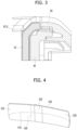
- FIG. 3 is a diagram for illustrating coupling of a display including a plastic cover lens having a plurality of curvatures according to one embodiment of the present disclosure.
- the corner of the plastic cover lens 10 may be formed to have a curvature. Therefore, the plastic cover lens 10 may be assembled in the display 100 for the vehicle integrally up to the corners thereof without any gaps. Such corners may contribute to preventing the display 100 for the vehicle from being easily damaged by the head-impact applied to the display 100 for the vehicle when the vehicle collides.
- the illustrated example shows a case in which the corner of the plastic cover lens 10 has a curvature of R2.5.
- the curvature may have a value within a range from R2 to R3 when necessary, but may not be necessarily limited to such range. That is, the corner of the plastic cover lens may be rounded with a radius in a range from 2 mm to 3 mm.
- the gap for the assembly is required in the front surface of the panel-front 40 to prevent the exposure of the corner thereof and the significant increase in the processing cost is required to realize such a corner.
- the plastic cover lens 10 such a shape may be implemented relatively inexpensively.
- FIG. 4 is a diagram illustrating a plastic cover lens having a plurality of curvatures according to an embodiment of the present disclosure.
- the plastic cover lens 10 having the plurality of curvatures may be disposed on the outermost surface of the display for the vehicle toward the driver.
- the display 100 for the vehicle may include a first area located at a left side and a second area located at a right side when viewed by the driver. Because the display 100 for the vehicle is located on a right side when viewed by the driver, the display 100 may have a slightly more curved shape toward the driver. That is, the second area of the plastic cover lens 10 may have the slightly more curved shape toward the driver based on the first area. A bent portion 330 having a relatively small radius of curvature is formed between the first and second areas 310 and 320, so that the second area 220 faces the driver.
- a first radius of curvature may be applied such that a radius of curvature of the bent portion is greater than a radius of curvature of the first area, and a radius of curvature of the second area is greater than the radius of curvature of the bent portion.
- the plastic cover lens 10 may be formed to be gently bent with a first radius of curvature 410 (e.g., R9000 or R12000) in a horizontal direction, and the plastic cover lens 10 may be formed such that a second radius of curvature 420 (e.g., R1800) is also applied in a vertical direction of the plastic cover lens 10 so as to become a concave lens and a third radius of curvature 430 is also applied to the corner of the plastic cover lens 10.
- a first radius of curvature 410 e.g., R9000 or R12000
- a second radius of curvature 420 e.g., R1800
- the plastic cover lens 10 may be formed in a shape having a 3D curvature via the plurality of curvatures on the front surface thereof, so that light incident on the front surface of the lens and reflected toward the driver is minimized.
Landscapes
- Physics & Mathematics (AREA)
- Engineering & Computer Science (AREA)
- Chemical & Material Sciences (AREA)
- Nonlinear Science (AREA)
- General Physics & Mathematics (AREA)
- Optics & Photonics (AREA)
- Mechanical Engineering (AREA)
- Transportation (AREA)
- Combustion & Propulsion (AREA)
- Crystallography & Structural Chemistry (AREA)
- Mathematical Physics (AREA)
- Theoretical Computer Science (AREA)
- Manufacturing & Machinery (AREA)
- Devices For Indicating Variable Information By Combining Individual Elements (AREA)
- Liquid Crystal (AREA)
- Fittings On The Vehicle Exterior For Carrying Loads, And Devices For Holding Or Mounting Articles (AREA)
- Instrument Panels (AREA)
Abstract
Description
- This application claims the benefit of
Korean Patent Application No. 10-2022-0146255, filed on November 4, 2022 - The present disclosure relates to a display for a vehicle including a plastic cover lens disposed in a cluster and a center fascia of the vehicle.
- Contents described in this section simply provide background information for the present embodiment and do not constitute prior art.
- A cluster provides various types of information related to a travel state of a vehicle to a driver as visual information. A speed of the vehicle, an engine RPM, a fuel amount, a thermometer, and various warnings are displayed. In addition, a display installed in a center fascia provides various additional convenient information including a navigation to the driver. As the vehicle becomes smarter, an amount of information provided by the cluster increases.
- On the other hand, light is introduced into the cluster of the traveling vehicle from various angles and the light is reflected toward a line of sight of the driver, making it difficult to grasp instrument panel information. In general, a shielding wall surrounding the cluster and protruding in a direction of the driver significantly reduces an amount of light entering the instrument panel. However, compared to a conventional analog-type cluster, the display for the vehicle is more likely to reflect stray light that hinders driver's identification of the instrument panel because a liquid crystal display module thereof is disposed over a large area.
- Most of popular displays for the vehicle are still in a flat shape, but starting with high-end vehicles, large glass lenses that reduce the effect of the reflected light and improve visibility because of a three-dimensional curved front lens are being applied. The glass lens is easy to secure an optical performance in harsh vehicle environments such as temperature, humidity, and vibration, but a high manufacturing cost for three-dimensional molding is pointed out as an obstacle to popularization.
- In order to solve the above problems, one embodiment of the present disclosure is to provide a display for a vehicle that reduces manufacturing costs, provides sufficient durability and optical performance required for the display for the vehicle, and is advantageous for enlargement by applying a plastic cover lens instead of a glass lens as a lens of the display for the vehicle having a three-dimensional shape.
- The problems to be solved in the present disclosure are not limited to the technical problems mentioned above, and other technical problems not mentioned will be clearly understood by those skilled in the art to which the present disclosure belongs from the description below.
- A display for a vehicle according to one of the embodiments of the present disclosure to solve the above-described problem includes a plastic cover lens including a lens, a front film disposed on a front surface of the lens, and a rear film disposed on a rear surface of the lens, a super retardation film (SRF) adhered to a rear surface of the plastic cover lens using an optically clear adhesive (OCA), a liquid crystal display module adhered to a rear surface of the super retardation film using the optically clear adhesive, a panel-front assembled at the rear of the plastic cover lens, in close contact with and supporting the liquid crystal display module, and preventing deformation of the plastic cover lens, and a rear cover assembled at the rear of the panel-front.
- In one implementation, the front film includes an anti-reflection (AR) coating layer and an anti-fingerprint (AF) coating layer formed at a front surface of the plastic cover lens via vacuum deposition.
- In one implementation, the rear film includes a black masking layer printed on the rear surface of the lens excluding a window area corresponding to a position of the liquid crystal display module.
- In one implementation, the plastic cover lens includes the front film and the rear film pre-molded in a shape of the plastic cover lens and is formed via insert mold labeling (IML).
- In one implementation, the plastic cover lens is formed such that a residual stress resulted from injection is minimized as the front film is disposed in an upper core of a mold and the rear film is disposed in a lower core of the mold and are pressurized to simultaneously perform injection-compression molding (ICM) during in-mold molding.
- In one implementation, the plastic cover lens includes a first area disposed on a side of a driver, a second area disposed on an opposite side of the first area, and a bent portion disposed between the first area and the second area.
- In one implementation, a first radius of curvature of the plastic cover lens is applied such that a radius of curvature of the bent portion is greater than a radius of curvature of the first area and a radius of curvature of the second area is greater than the radius of curvature of the bent portion.
- In one implementation, the plastic cover lens is formed in a shape having a 3D curvature as the first radius of curvature is applied to the plastic cover lens in a horizontal direction, a second radius of curvature is applied to the plastic cover lens in a vertical direction for the plastic cover lens to become a concave lens, and a third radius of curvature is applied to a corner of the plastic cover lens.
- In one implementation, the corner of the plastic cover lens is formed to be rounded with a radius in a range from 2 mm to 3 mm.
- In one implementation, the display further includes a carrier-bezel mechanically coupled to an edge of the plastic cover lens to firmly maintain a shape of the plastic cover lens.
- In one implementation, the display further includes an adhesive tape adhered to at least a portion of the rear surface of the plastic cover lens to couple the plastic cover lens and the carrier-bezel to each other.
- According to one of the embodiments of the present disclosure, the three-dimensional shape may be easily implemented by applying the plastic cover lens as the lens for the display for the vehicle.
- According to one of the embodiments of the present disclosure, the manufacturing costs may be significantly reduced by reducing the gate wash-out caused by the insert mold labeling (IML) scheme via the placement of the black masking layer on the rear surface of the plastic cover lens of the display for the vehicle.
- The effects obtainable from the present disclosure are not limited to the effects mentioned above, and other effects not mentioned will be clearly understood by those skilled in the art from the description below.
-
-
FIG. 1 is an exploded perspective view of a display for a vehicle including a plastic cover lens according to one embodiment of the present disclosure. -
FIG. 2 is a diagram illustrating a cross-sectional configuration of a display for a vehicle including a plastic cover lens according to an embodiment of the present disclosure. -
FIG. 3 is a diagram for illustrating coupling of a display including a plastic cover lens having a plurality of curvatures according to one embodiment of the present disclosure. -
FIG. 4 is a diagram illustrating a plastic cover lens having a plurality of curvatures according to an embodiment of the present disclosure. - Hereinafter, with reference to the accompanying drawings, the embodiment of the present disclosure will be described in detail such that a person having ordinary knowledge in the technical field to which the present disclosure belongs may easily practice the same. However, the present disclosure is able to be implemented in many different forms and is not limited to the embodiment described herein. In addition, in order to clearly illustrate the present disclosure in the drawings, components irrelevant to the description are omitted and similar reference numerals are assigned to similar components throughout the present document.
- Throughout the present document, when a component is referred to as "including" another component, it implies a presence of the latter component, along with a possibility of additional components, unless otherwise stated.
-
FIG. 1 is an exploded perspective view of a display for a vehicle including a plastic cover lens according to one embodiment of the present disclosure. - Referring to
FIG. 1 , adisplay 100 for a vehicle including a plastic cover lens according to one embodiment may include aplastic cover lens 10, anoptical bonding layer 20, a liquidcrystal display module 30, a panel-front 40, brackets 51 and 52, and arear cover 60. - As the
display 100 for the vehicle, a console display that displays various convenient information such as a navigation is disposed in a cluster and a center fascia that display a basic state of the vehicle. A case in which thedisplay 100 for the vehicle includes theplastic cover lens 10 and is disposed across the cluster and the center fascia in front of a driver will be exemplified. Theplastic cover lens 10 having a plurality of curvatures is disposed on an outermost surface of thedisplay 100 for the vehicle toward the driver, that is, at a front portion of thedisplay 100 for the vehicle. - The
plastic cover lens 10 may include alens 11, afront film 12 disposed on a front surface of the lens, which is the outermost surface toward the driver, and arear film 13 disposed on a rear surface of the lens. - The
lens 11 may be manufactured by high fluidity PC clear injection molding. Thefront film 12 including anti-reflection (AR) and anti-fingerprint (AF) coating layers may be disposed on the front surface of the lens 110 by vacuum deposition. Thefront film 12 may be formed to realize hardness and transparency of theplastic cover lens 10. - The
rear film 13 may be disposed on the rear surface of thelens 11, and the rear film may include a black masking layer. In this regard, the black masking layer may be printed except for a window area corresponding to a position of the liquid crystal display (LCD) module. - The
plastic cover lens 10 exhibits an excellent optical property by molding the front film and a second film in a predetermined shape, inserting a first film into an upper core of a mold and inserting the rear film into a lower core of the mold, and performing compression molding during injection. Theplastic cover lens 10 has an effect of reducing reflection of stray light by applying compression injection to minimize birefringence. - For example, the
plastic cover lens 10 may be formed in an insert mold labeling (IML) scheme. In this scheme, the front film and therear film lens 11 beforehand, then inserted into the mold, and then finally molded with plastic inserted from the rear. In such manner, a hard coated film material may be used, so that a considerable level of abrasion resistance may be secured. In addition, because the different films may be manufactured using the same plastic cover lens mold, a variety of products may be manufactured in small quantities. - For example, the
plastic cover lens 10 may be formed in an injection-compression molding (ICM) scheme. The injection-compression molding may be performed along with the insert mold labeling. Therefore, after the molding of theplastic cover lens 10, a density of theplastic cover lens 10 may be maintained more uniformly throughout a body and a residual stress of the injection-molded product resulted from a difference in a cooling speed depending on a shape of the lens and a structure of the mold may be minimized. - Because the black masking layer of the
plastic cover lens 10 is located on therear film 12, a gate wash-out problem caused by the insert mold labeling scheme may be prevented from occurring. - The
optical bonding layer 20 may include an optically clear adhesive (OCA) 21 and a super retardation film (SRF) 22. - The optically
clear adhesive 21 may be disposed on a rear surface of theplastic cover lens 10 to be optically in contact with a liquid crystal display (LCD). Thesuper retardation film 22 may be disposed between the opticallyclear adhesive 21 and the liquid crystal display (LCD). - On a front surface of the liquid crystal display, polarization may be applied and utilized in a complex manner to enhance a clarity, a viewing angle, and the like. When the driver wears sunglasses with a polarization function and looks at the liquid crystal display, a rainbow-shaped distortion may occur in an image displayed on the liquid crystal display because of the complex polarization states. Internal stress in the
plastic cover lens 10 causes a phase shift in transmitted light, resulting in increased birefringence and making such distortion more pronounced. In the present embodiment, to reduce such phenomenon, thesuper retardation film 22 may be bonded to the rear surface of theplastic cover lens 10 via direct bonding using the optically clear adhesive (OCA) 21. In such manner, theplastic cover lens 10 and thesuper retardation film 22 may act as one optical element. - Therefore, the
liquid crystal display 10 may be bonded a rear surface of thesuper retardation film 22 using the optically clear adhesive (OCA) such that the liquid crystal display to theplastic cover lens 10 act as one optical element and reflection at a bonding surface is minimized. The opticallyclear adhesive 21 may be disposed on the rear surface of thesuper retardation film 22 or on a front surface of the liquid crystal display and the liquid crystal display may be attached to the rear surface of thesuper retardation film 22 to bond the liquid crystal display to thesuper retardation film 22. - The liquid
crystal display module 30 may include the liquid crystal display (LCD) and a back light unit (BLU). - Because a front surface of the
plastic cover lens 10 and the injection-molded product are transparent, an assembly cannot be placed on the rear surface of theplastic cover lens 10, so that the panel-front 40 and the rear surface of theplastic cover lens 10 may be bonded together using an adhesive 70. - The panel-
front 40 is formed to have high structural rigidity and is coupled to theplastic cover lens 10 to maintain a design shape of theplastic cover lens 10. A remaining area of the rear surface of the panel-front 40 except for a pocket area formed to accommodate the liquid crystal display therein may be formed such that the panel-front 40 may have sufficiently high rigidity against bending while seeking weight reduction. - The
bracket 50 may be disposed on a rear surface of the panel-front to strengthen structural integrity and reinforce rigidity against head-impact. For example, thebracket 50 may be made of a steel material. - The
rear cover 60 may be formed to expose rear surfaces of upper ends of an installed structure and thedisplay 100 for the vehicle. -
FIG. 2 is a diagram illustrating a cross-sectional configuration of a display for a vehicle including a plastic cover lens according to an embodiment of the present disclosure. - Referring to
FIG. 2 , thefront film 12 including a hard coating layer and a clear layer may be disposed on the front surface of the moldedplastic cover lens 10. - Any coating composition capable of improving a surface hardness of the
plastic cover lens 10 may be used as the hard coating layer, but it is preferable to use an ultraviolet curable coating composition that does not require high-temperature treatment. The hard coating layer may contain an acrylate-based monomer or an inorganic compound. The hard coating layer serves to improve the surface hardness and at the same time increase chemical resistance of theplastic cover lens 10. - A protective layer may be disposed on the hard coating layer. The protective layer may be a functional coating layer including the anti-fingerprint coating layer (AF), the anti-reflection (AR) coating layer, and the like.
- The AR coating layer may be formed to secure light transmittance of the
plastic cover lens 10 and reduce reflectance of the plastic cover lens 10 (e.g., to be lower than 1.5 %). The AR coating layer may have a structure in which a plurality of media having different densities are stacked. Incident light may be reflected at each interface between two media, superposed each other in different phases, and then cancelled, thereby reducing a final reflected amount of light. - The AF coating layer prevents contamination of a surface of the
plastic cover lens 10 based n use of the user, so that visibility is not deteriorated. - The
rear film 13 including the black masking layer and an active area corresponding to the liquid crystal display may be disposed on the rear surface of theplastic cover lens 10. - Such
plastic cover lens 10 may be formed using the insert mold labeling scheme to include thefront film 12 and therear film 13. - The
plastic cover lens 10 according to one embodiment may be formed by printing or pattern-forming thefront film 12 and therear film 13 in advance to partially have a pattern on the front surface of theplastic cover lens 10 molded via the insert mold labeling. For example, an area where the liquid crystal display is disposed may be made transparent so as to have excellent light transmittance, while the remaining area may be treated to be opaque or translucent. - The
optical bonding layer 20 disposed on the active area of the rear surface of theplastic cover lens 10 may be composed of the front opticallyclear adhesive 21 in direct contact with therear film 12, thesuper retardation film 22 disposed on a rear surface of the front optically clear adhesive, and the rear opticallyclear adhesive 23 disposed on a rear surface of thesuper retardation film 22. - The liquid
crystal display module 30 bonded to theplastic cover lens 10 and theoptical bonding layer 20 may include the liquid crystal display and the backlight unit. In this regard, an area of a LCD panel may partially overlap an area of theoptical bonding layer 20. - In addition, the display for the vehicle may include a carrier-
bezel 80 disposed on the rear surface of the black masking layer of the rear surface of theplastic cover lens 10 and mechanically coupled to an edge of theplastic cover lens 10 to firmly maintain the shape of theplastic cover lens 10. - The carrier-
bezel 80 may be bonded by disposing anadhesive tape 90 on an area of theplastic cover lens 10 excluding the area where the liquid crystal display is disposed. Theadhesive tape 90 may be adhered to at least a portion of the rear surface of the plastic cover lens to couple theplastic cover lens 10 and the carrier-bezel 80 to each other. - For example, in the
plastic cover lens 10, the black masking layer is located on a front side compared to that in a glass lens and a gap between the black masking layer and the LCD panel is reduced during operation of the liquid crystal display, thereby reducing a depth of the LCD. - For example, the
plastic cover lens 10 needs a gap for assembly in a front surface of the panel-front 40 to prevent exposure of a corner thereof, and a significant increase in processing cost is required to realize such a corner. However, in theplastic cover lens 10, such a shape may be implemented relatively inexpensively. -
FIG. 3 is a diagram for illustrating coupling of a display including a plastic cover lens having a plurality of curvatures according to one embodiment of the present disclosure. - Referring to
FIG. 3 , the corner of theplastic cover lens 10 may be formed to have a curvature. Therefore, theplastic cover lens 10 may be assembled in thedisplay 100 for the vehicle integrally up to the corners thereof without any gaps. Such corners may contribute to preventing thedisplay 100 for the vehicle from being easily damaged by the head-impact applied to thedisplay 100 for the vehicle when the vehicle collides. - The illustrated example shows a case in which the corner of the
plastic cover lens 10 has a curvature of R2.5. The curvature may have a value within a range from R2 to R3 when necessary, but may not be necessarily limited to such range. That is, the corner of the plastic cover lens may be rounded with a radius in a range from 2 mm to 3 mm. - In the case of the glass lens, the gap for the assembly is required in the front surface of the panel-
front 40 to prevent the exposure of the corner thereof and the significant increase in the processing cost is required to realize such a corner. However, in theplastic cover lens 10, such a shape may be implemented relatively inexpensively. -
FIG. 4 is a diagram illustrating a plastic cover lens having a plurality of curvatures according to an embodiment of the present disclosure. - Referring to
FIG. 4 , theplastic cover lens 10 having the plurality of curvatures may be disposed on the outermost surface of the display for the vehicle toward the driver. - The
display 100 for the vehicle may include a first area located at a left side and a second area located at a right side when viewed by the driver. Because thedisplay 100 for the vehicle is located on a right side when viewed by the driver, thedisplay 100 may have a slightly more curved shape toward the driver. That is, the second area of theplastic cover lens 10 may have the slightly more curved shape toward the driver based on the first area. Abent portion 330 having a relatively small radius of curvature is formed between the first andsecond areas - Therefore, in the
plastic cover lens 10, a first radius of curvature may be applied such that a radius of curvature of the bent portion is greater than a radius of curvature of the first area, and a radius of curvature of the second area is greater than the radius of curvature of the bent portion. - The
plastic cover lens 10 may be formed to be gently bent with a first radius of curvature 410 (e.g., R9000 or R12000) in a horizontal direction, and theplastic cover lens 10 may be formed such that a second radius of curvature 420 (e.g., R1800) is also applied in a vertical direction of theplastic cover lens 10 so as to become a concave lens and a third radius ofcurvature 430 is also applied to the corner of theplastic cover lens 10. - The
plastic cover lens 10 may be formed in a shape having a 3D curvature via the plurality of curvatures on the front surface thereof, so that light incident on the front surface of the lens and reflected toward the driver is minimized. - A detailed description of the preferred embodiments of the present disclosure disclosed as described above is provided such that those skilled in the art may implement and practice the present disclosure. Although the description has been made with reference to the preferred embodiments of the present disclosure, those skilled in the art will be able to understand that the present disclosure may be variously modified and changed within a range that does not deviate from the scope of the present disclosure. For example, those skilled in the art may use respective components described in the above-described embodiments in a way of combining them with each other.
- Thus, the present disclosure is not intended to be limited to the embodiments illustrated herein but is to be accorded the widest scope consistent with the principles and novel features disclosed herein.
Claims (11)
- A display for a vehicle, comprising:a plastic cover lens including a lens, a front film disposed on a front surface of the lens, and a rear film disposed on a rear surface of the lens;a super retardation film (SRF) adhered to a rear surface of the plastic cover lens using an optically clear adhesive (OCA);a liquid crystal display module adhered to a rear surface of the super retardation film using the optically clear adhesive;a panel-front assembled at the rear of the plastic cover lens, in close contact with and supporting the liquid crystal display module, and preventing deformation of the plastic cover lens; anda rear cover assembled at the rear of the panel-front.
- The display of claim 1, wherein the front film includes an anti-reflection (AR) coating layer and an anti-fingerprint (AF) coating layer formed at a front surface of the plastic cover lens via vacuum deposition.
- The display of claim 1 or 2, wherein the rear film includes a black masking layer printed on the rear surface of the lens excluding a window area corresponding to a position of the liquid crystal display module.
- The display of any one of claims 1 to 3, wherein the plastic cover lens includes the front film and the rear film pre-molded in a shape of the plastic cover lens and is formed via insert mold labeling (IML).
- The display of any one of claims 1 to 4, wherein the plastic cover lens is formed such that a residual stress resulted from injection is minimized as the front film is disposed in an upper core of a mold and the rear film is disposed in a lower core of the mold and are pressurized to simultaneously perform injection-compression molding (ICM) during in-mold molding.
- The display of any one of claims 1 to 5, wherein the plastic cover lens includes a first area disposed on a side of a driver, a second area disposed on an opposite side of the first area, and a bent portion disposed between the first area and the second area.
- The display of claim 6, wherein a first radius of curvature of the plastic cover lens is applied such that a radius of curvature of the bent portion is greater than a radius of curvature of the first area and a radius of curvature of the second area is greater than the radius of curvature of the bent portion.
- The display of claim 7, wherein the plastic cover lens is formed in a shape having a 3D curvature as the first radius of curvature is applied to the plastic cover lens in a horizontal direction, a second radius of curvature is applied to the plastic cover lens in a vertical direction for the plastic cover lens to become a concave lens, and a third radius of curvature is applied to a corner of the plastic cover lens.
- The display of claim 8, wherein the corner of the plastic cover lens is formed to be rounded with a radius in a range from 2 mm to 3 mm.
- The display of any one of claims 1 to 9, further comprising a carrier-bezel mechanically coupled to an edge of the plastic cover lens to firmly maintain a shape of the plastic cover lens.
- The display of claim 10, further comprising an adhesive tape adhered to at least a portion of the rear surface of the plastic cover lens to couple the plastic cover lens and the carrier-bezel to each other.
Applications Claiming Priority (1)
| Application Number | Priority Date | Filing Date | Title |
|---|---|---|---|
| KR1020220146255A KR102763952B1 (en) | 2022-11-04 | 2022-11-04 | Plastic cover lens and vehicle display including same |
Publications (2)
| Publication Number | Publication Date |
|---|---|
| EP4364993A1 true EP4364993A1 (en) | 2024-05-08 |
| EP4364993B1 EP4364993B1 (en) | 2025-07-23 |
Family
ID=86282487
Family Applications (1)
| Application Number | Title | Priority Date | Filing Date |
|---|---|---|---|
| EP23170394.3A Active EP4364993B1 (en) | 2022-11-04 | 2023-04-27 | Display for vehicle including a plastic cover lens |
Country Status (5)
| Country | Link |
|---|---|
| US (1) | US20240149683A1 (en) |
| EP (1) | EP4364993B1 (en) |
| JP (1) | JP2024068071A (en) |
| KR (1) | KR102763952B1 (en) |
| CN (1) | CN117991540A (en) |
Citations (3)
| Publication number | Priority date | Publication date | Assignee | Title |
|---|---|---|---|---|
| US9465472B1 (en) * | 2014-08-29 | 2016-10-11 | Amazon Technologies, Inc. | Metal mesh touch sensor with low birefringence substrate and ultraviolet cut |
| FR3097478A1 (en) * | 2019-06-24 | 2020-12-25 | Novares France | Dashboard of a motor vehicle |
| US20210109396A1 (en) * | 2019-10-15 | 2021-04-15 | Hyundai Mobis Co., Ltd. | Digital instrument cluster comprising dual display plastic lens |
Family Cites Families (2)
| Publication number | Priority date | Publication date | Assignee | Title |
|---|---|---|---|---|
| EP3681847B1 (en) * | 2017-09-12 | 2025-01-29 | Corning Incorporated | Tactile elements for deadfronted glass and methods of making the same |
| CN112867625B (en) * | 2018-08-20 | 2025-03-28 | 康宁公司 | Strengthened cover glass for display or touch panel |
-
2022
- 2022-11-04 KR KR1020220146255A patent/KR102763952B1/en active Active
-
2023
- 2023-03-30 US US18/192,782 patent/US20240149683A1/en active Pending
- 2023-04-10 JP JP2023063570A patent/JP2024068071A/en active Pending
- 2023-04-25 CN CN202310458455.7A patent/CN117991540A/en active Pending
- 2023-04-27 EP EP23170394.3A patent/EP4364993B1/en active Active
Patent Citations (3)
| Publication number | Priority date | Publication date | Assignee | Title |
|---|---|---|---|---|
| US9465472B1 (en) * | 2014-08-29 | 2016-10-11 | Amazon Technologies, Inc. | Metal mesh touch sensor with low birefringence substrate and ultraviolet cut |
| FR3097478A1 (en) * | 2019-06-24 | 2020-12-25 | Novares France | Dashboard of a motor vehicle |
| US20210109396A1 (en) * | 2019-10-15 | 2021-04-15 | Hyundai Mobis Co., Ltd. | Digital instrument cluster comprising dual display plastic lens |
Also Published As
| Publication number | Publication date |
|---|---|
| KR102763952B1 (en) | 2025-02-07 |
| CN117991540A (en) | 2024-05-07 |
| US20240149683A1 (en) | 2024-05-09 |
| JP2024068071A (en) | 2024-05-17 |
| KR20240064350A (en) | 2024-05-13 |
| EP4364993B1 (en) | 2025-07-23 |
Similar Documents
| Publication | Publication Date | Title |
|---|---|---|
| US11409146B2 (en) | Digital instrument cluster comprising dual display plastic lens | |
| US20200192148A1 (en) | Display Device | |
| US10586944B2 (en) | Display device having window member and method of manufacturing window member | |
| CN111028670A (en) | Cover window of display device | |
| JP6457270B2 (en) | Control display module for automobile | |
| US20210202622A1 (en) | Display apparatus | |
| CN113126343A (en) | Display device | |
| CN101470217A (en) | display device | |
| TWI534501B (en) | Liquid crystal display device and manufacturing method thereof | |
| EP4364993A1 (en) | Display for vehicle including a plastic cover lens | |
| US20220326517A1 (en) | Head-up display screen, head-up display assembly, and vehicle | |
| WO2026082029A1 (en) | Laminated glass, projection system and vehicle | |
| JPH10119163A (en) | Hologram laminate and manufacturing method thereof | |
| JP2003005662A (en) | Display device with protective plate and protective plate suitable for it | |
| JPH0511239A (en) | Lcd display | |
| US12128653B2 (en) | Display device and method for manufacturing same | |
| JP2019150952A (en) | Cover panel and its manufacturing method | |
| CN214775616U (en) | A kind of bias mirror | |
| CN113035061A (en) | Cover plate assembly, preparation method thereof and display device | |
| WO2021049474A1 (en) | Display device | |
| JP2017004474A (en) | Low reflection type capacitance type display device with touch panel function | |
| KR102828882B1 (en) | Improved electronic paper display module bonding structure | |
| US20240210746A1 (en) | Display device | |
| TWI861749B (en) | Composite-type high scratch-resistant optical lens device and manufacturing method thereof | |
| JPH1110674A (en) | Method for producing hologram laminate |
Legal Events
| Date | Code | Title | Description |
|---|---|---|---|
| PUAI | Public reference made under article 153(3) epc to a published international application that has entered the european phase |
Free format text: ORIGINAL CODE: 0009012 |
|
| STAA | Information on the status of an ep patent application or granted ep patent |
Free format text: STATUS: THE APPLICATION HAS BEEN PUBLISHED |
|
| AK | Designated contracting states |
Kind code of ref document: A1 Designated state(s): AL AT BE BG CH CY CZ DE DK EE ES FI FR GB GR HR HU IE IS IT LI LT LU LV MC ME MK MT NL NO PL PT RO RS SE SI SK SM TR |
|
| STAA | Information on the status of an ep patent application or granted ep patent |
Free format text: STATUS: REQUEST FOR EXAMINATION WAS MADE |
|
| 17P | Request for examination filed |
Effective date: 20241021 |
|
| REG | Reference to a national code |
Ref country code: DE Ref legal event code: R079 Free format text: PREVIOUS MAIN CLASS: B60K0035000000 Ipc: B29C0045000000 Ref document number: 602023004950 Country of ref document: DE |
|
| RIC1 | Information provided on ipc code assigned before grant |
Ipc: G02F 1/1337 20060101ALI20250116BHEP Ipc: G02F 1/1335 20060101ALI20250116BHEP Ipc: G02F 1/1333 20060101ALI20250116BHEP Ipc: G02B 1/18 20150101ALI20250116BHEP Ipc: G02B 1/11 20150101ALI20250116BHEP Ipc: B60K 35/40 20240101ALI20250116BHEP Ipc: B60K 35/22 20240101ALI20250116BHEP Ipc: B29C 45/56 20060101ALI20250116BHEP Ipc: B29C 45/16 20060101ALI20250116BHEP Ipc: B29C 45/14 20060101ALI20250116BHEP Ipc: B29C 45/00 20060101AFI20250116BHEP |
|
| GRAP | Despatch of communication of intention to grant a patent |
Free format text: ORIGINAL CODE: EPIDOSNIGR1 |
|
| STAA | Information on the status of an ep patent application or granted ep patent |
Free format text: STATUS: GRANT OF PATENT IS INTENDED |
|
| INTG | Intention to grant announced |
Effective date: 20250307 |
|
| P01 | Opt-out of the competence of the unified patent court (upc) registered |
Free format text: CASE NUMBER: APP_21683/2025 Effective date: 20250507 |
|
| GRAS | Grant fee paid |
Free format text: ORIGINAL CODE: EPIDOSNIGR3 |
|
| GRAA | (expected) grant |
Free format text: ORIGINAL CODE: 0009210 |
|
| STAA | Information on the status of an ep patent application or granted ep patent |
Free format text: STATUS: THE PATENT HAS BEEN GRANTED |
|
| AK | Designated contracting states |
Kind code of ref document: B1 Designated state(s): AL AT BE BG CH CY CZ DE DK EE ES FI FR GB GR HR HU IE IS IT LI LT LU LV MC ME MK MT NL NO PL PT RO RS SE SI SK SM TR |
|
| REG | Reference to a national code |
Ref country code: GB Ref legal event code: FG4D |
|
| REG | Reference to a national code |
Ref country code: CH Ref legal event code: EP |
|
| REG | Reference to a national code |
Ref country code: DE Ref legal event code: R096 Ref document number: 602023004950 Country of ref document: DE |
|
| REG | Reference to a national code |
Ref country code: IE Ref legal event code: FG4D |
|
| REG | Reference to a national code |
Ref country code: NL Ref legal event code: MP Effective date: 20250723 |
|
| PG25 | Lapsed in a contracting state [announced via postgrant information from national office to epo] |
Ref country code: PT Free format text: LAPSE BECAUSE OF FAILURE TO SUBMIT A TRANSLATION OF THE DESCRIPTION OR TO PAY THE FEE WITHIN THE PRESCRIBED TIME-LIMIT Effective date: 20251124 |
|
| PG25 | Lapsed in a contracting state [announced via postgrant information from national office to epo] |
Ref country code: NL Free format text: LAPSE BECAUSE OF FAILURE TO SUBMIT A TRANSLATION OF THE DESCRIPTION OR TO PAY THE FEE WITHIN THE PRESCRIBED TIME-LIMIT Effective date: 20250723 |
|
| REG | Reference to a national code |
Ref country code: AT Ref legal event code: MK05 Ref document number: 1816003 Country of ref document: AT Kind code of ref document: T Effective date: 20250723 |
|
| PG25 | Lapsed in a contracting state [announced via postgrant information from national office to epo] |
Ref country code: IS Free format text: LAPSE BECAUSE OF FAILURE TO SUBMIT A TRANSLATION OF THE DESCRIPTION OR TO PAY THE FEE WITHIN THE PRESCRIBED TIME-LIMIT Effective date: 20251123 |
|
| PG25 | Lapsed in a contracting state [announced via postgrant information from national office to epo] |
Ref country code: NO Free format text: LAPSE BECAUSE OF FAILURE TO SUBMIT A TRANSLATION OF THE DESCRIPTION OR TO PAY THE FEE WITHIN THE PRESCRIBED TIME-LIMIT Effective date: 20251023 |
|
| REG | Reference to a national code |
Ref country code: LT Ref legal event code: MG9D |
|
| PG25 | Lapsed in a contracting state [announced via postgrant information from national office to epo] |
Ref country code: AT Free format text: LAPSE BECAUSE OF FAILURE TO SUBMIT A TRANSLATION OF THE DESCRIPTION OR TO PAY THE FEE WITHIN THE PRESCRIBED TIME-LIMIT Effective date: 20250723 |
|
| PG25 | Lapsed in a contracting state [announced via postgrant information from national office to epo] |
Ref country code: FI Free format text: LAPSE BECAUSE OF FAILURE TO SUBMIT A TRANSLATION OF THE DESCRIPTION OR TO PAY THE FEE WITHIN THE PRESCRIBED TIME-LIMIT Effective date: 20250723 |
|
| PG25 | Lapsed in a contracting state [announced via postgrant information from national office to epo] |
Ref country code: HR Free format text: LAPSE BECAUSE OF FAILURE TO SUBMIT A TRANSLATION OF THE DESCRIPTION OR TO PAY THE FEE WITHIN THE PRESCRIBED TIME-LIMIT Effective date: 20250723 |
|
| PG25 | Lapsed in a contracting state [announced via postgrant information from national office to epo] |
Ref country code: GR Free format text: LAPSE BECAUSE OF FAILURE TO SUBMIT A TRANSLATION OF THE DESCRIPTION OR TO PAY THE FEE WITHIN THE PRESCRIBED TIME-LIMIT Effective date: 20251024 |
|
| PG25 | Lapsed in a contracting state [announced via postgrant information from national office to epo] |
Ref country code: SE Free format text: LAPSE BECAUSE OF FAILURE TO SUBMIT A TRANSLATION OF THE DESCRIPTION OR TO PAY THE FEE WITHIN THE PRESCRIBED TIME-LIMIT Effective date: 20250723 |
|
| PG25 | Lapsed in a contracting state [announced via postgrant information from national office to epo] |
Ref country code: LV Free format text: LAPSE BECAUSE OF FAILURE TO SUBMIT A TRANSLATION OF THE DESCRIPTION OR TO PAY THE FEE WITHIN THE PRESCRIBED TIME-LIMIT Effective date: 20250723 |
|
| PG25 | Lapsed in a contracting state [announced via postgrant information from national office to epo] |
Ref country code: BG Free format text: LAPSE BECAUSE OF FAILURE TO SUBMIT A TRANSLATION OF THE DESCRIPTION OR TO PAY THE FEE WITHIN THE PRESCRIBED TIME-LIMIT Effective date: 20250723 Ref country code: PL Free format text: LAPSE BECAUSE OF FAILURE TO SUBMIT A TRANSLATION OF THE DESCRIPTION OR TO PAY THE FEE WITHIN THE PRESCRIBED TIME-LIMIT Effective date: 20250723 |
|
| PG25 | Lapsed in a contracting state [announced via postgrant information from national office to epo] |
Ref country code: RS Free format text: LAPSE BECAUSE OF FAILURE TO SUBMIT A TRANSLATION OF THE DESCRIPTION OR TO PAY THE FEE WITHIN THE PRESCRIBED TIME-LIMIT Effective date: 20251023 |
|
| PG25 | Lapsed in a contracting state [announced via postgrant information from national office to epo] |
Ref country code: ES Free format text: LAPSE BECAUSE OF FAILURE TO SUBMIT A TRANSLATION OF THE DESCRIPTION OR TO PAY THE FEE WITHIN THE PRESCRIBED TIME-LIMIT Effective date: 20250723 |
|
| PG25 | Lapsed in a contracting state [announced via postgrant information from national office to epo] |
Ref country code: SM Free format text: LAPSE BECAUSE OF FAILURE TO SUBMIT A TRANSLATION OF THE DESCRIPTION OR TO PAY THE FEE WITHIN THE PRESCRIBED TIME-LIMIT Effective date: 20250723 |
|
| PG25 | Lapsed in a contracting state [announced via postgrant information from national office to epo] |
Ref country code: DK Free format text: LAPSE BECAUSE OF FAILURE TO SUBMIT A TRANSLATION OF THE DESCRIPTION OR TO PAY THE FEE WITHIN THE PRESCRIBED TIME-LIMIT Effective date: 20250723 |
|
| PG25 | Lapsed in a contracting state [announced via postgrant information from national office to epo] |
Ref country code: IT Free format text: LAPSE BECAUSE OF FAILURE TO SUBMIT A TRANSLATION OF THE DESCRIPTION OR TO PAY THE FEE WITHIN THE PRESCRIBED TIME-LIMIT Effective date: 20250723 |
|
| PGFP | Annual fee paid to national office [announced via postgrant information from national office to epo] |
Ref country code: FR Payment date: 20260224 Year of fee payment: 4 |
|
| PG25 | Lapsed in a contracting state [announced via postgrant information from national office to epo] |
Ref country code: CZ Free format text: LAPSE BECAUSE OF FAILURE TO SUBMIT A TRANSLATION OF THE DESCRIPTION OR TO PAY THE FEE WITHIN THE PRESCRIBED TIME-LIMIT Effective date: 20250723 |
|
| PG25 | Lapsed in a contracting state [announced via postgrant information from national office to epo] |
Ref country code: EE Free format text: LAPSE BECAUSE OF FAILURE TO SUBMIT A TRANSLATION OF THE DESCRIPTION OR TO PAY THE FEE WITHIN THE PRESCRIBED TIME-LIMIT Effective date: 20250723 Ref country code: SK Free format text: LAPSE BECAUSE OF FAILURE TO SUBMIT A TRANSLATION OF THE DESCRIPTION OR TO PAY THE FEE WITHIN THE PRESCRIBED TIME-LIMIT Effective date: 20250723 |