EP4364984A1 - Insulation, evaporator structure, cutting die, and method for producing insulation - Google Patents
Insulation, evaporator structure, cutting die, and method for producing insulation Download PDFInfo
- Publication number
- EP4364984A1 EP4364984A1 EP22852648.9A EP22852648A EP4364984A1 EP 4364984 A1 EP4364984 A1 EP 4364984A1 EP 22852648 A EP22852648 A EP 22852648A EP 4364984 A1 EP4364984 A1 EP 4364984A1
- Authority
- EP
- European Patent Office
- Prior art keywords
- pair
- wing portions
- portions
- cutting teeth
- strip portion
- Prior art date
- Legal status (The legal status is an assumption and is not a legal conclusion. Google has not performed a legal analysis and makes no representation as to the accuracy of the status listed.)
- Withdrawn
Links
Images




Classifications
-
- F—MECHANICAL ENGINEERING; LIGHTING; HEATING; WEAPONS; BLASTING
- F28—HEAT EXCHANGE IN GENERAL
- F28D—HEAT-EXCHANGE APPARATUS, NOT PROVIDED FOR IN ANOTHER SUBCLASS, IN WHICH THE HEAT-EXCHANGE MEDIA DO NOT COME INTO DIRECT CONTACT
- F28D1/00—Heat-exchange apparatus having stationary conduit assemblies for one heat-exchange medium only, the media being in contact with different sides of the conduit wall, in which the other heat-exchange medium is a large body of fluid, e.g. domestic or motor car radiators
- F28D1/02—Heat-exchange apparatus having stationary conduit assemblies for one heat-exchange medium only, the media being in contact with different sides of the conduit wall, in which the other heat-exchange medium is a large body of fluid, e.g. domestic or motor car radiators with heat-exchange conduits immersed in the body of fluid
- F28D1/04—Heat-exchange apparatus having stationary conduit assemblies for one heat-exchange medium only, the media being in contact with different sides of the conduit wall, in which the other heat-exchange medium is a large body of fluid, e.g. domestic or motor car radiators with heat-exchange conduits immersed in the body of fluid with tubular conduits
- F28D1/053—Heat-exchange apparatus having stationary conduit assemblies for one heat-exchange medium only, the media being in contact with different sides of the conduit wall, in which the other heat-exchange medium is a large body of fluid, e.g. domestic or motor car radiators with heat-exchange conduits immersed in the body of fluid with tubular conduits the conduits being straight
- F28D1/0535—Heat-exchange apparatus having stationary conduit assemblies for one heat-exchange medium only, the media being in contact with different sides of the conduit wall, in which the other heat-exchange medium is a large body of fluid, e.g. domestic or motor car radiators with heat-exchange conduits immersed in the body of fluid with tubular conduits the conduits being straight the conduits having a non-circular cross-section
- F28D1/05366—Assemblies of conduits connected to common headers, e.g. core type radiators
- F28D1/05383—Assemblies of conduits connected to common headers, e.g. core type radiators with multiple rows of conduits or with multi-channel conduits
-
- B—PERFORMING OPERATIONS; TRANSPORTING
- B60—VEHICLES IN GENERAL
- B60H—ARRANGEMENTS OF HEATING, COOLING, VENTILATING OR OTHER AIR-TREATING DEVICES SPECIALLY ADAPTED FOR PASSENGER OR GOODS SPACES OF VEHICLES
- B60H1/00—Heating, cooling or ventilating devices
- B60H1/00321—Heat exchangers for air-conditioning devices
-
- B—PERFORMING OPERATIONS; TRANSPORTING
- B60—VEHICLES IN GENERAL
- B60H—ARRANGEMENTS OF HEATING, COOLING, VENTILATING OR OTHER AIR-TREATING DEVICES SPECIALLY ADAPTED FOR PASSENGER OR GOODS SPACES OF VEHICLES
- B60H1/00—Heating, cooling or ventilating devices
- B60H1/00507—Details, e.g. mounting arrangements, desaeration devices
- B60H2001/00635—Air-tight sealing devices
-
- F—MECHANICAL ENGINEERING; LIGHTING; HEATING; WEAPONS; BLASTING
- F28—HEAT EXCHANGE IN GENERAL
- F28D—HEAT-EXCHANGE APPARATUS, NOT PROVIDED FOR IN ANOTHER SUBCLASS, IN WHICH THE HEAT-EXCHANGE MEDIA DO NOT COME INTO DIRECT CONTACT
- F28D21/00—Heat-exchange apparatus not covered by any of the groups F28D1/00 - F28D20/00
- F28D2021/0019—Other heat exchangers for particular applications; Heat exchange systems not otherwise provided for
- F28D2021/008—Other heat exchangers for particular applications; Heat exchange systems not otherwise provided for for vehicles
- F28D2021/0085—Evaporators
-
- F—MECHANICAL ENGINEERING; LIGHTING; HEATING; WEAPONS; BLASTING
- F28—HEAT EXCHANGE IN GENERAL
- F28F—DETAILS OF HEAT-EXCHANGE AND HEAT-TRANSFER APPARATUS, OF GENERAL APPLICATION
- F28F2270/00—Thermal insulation; Thermal decoupling
Definitions
- the present disclosure relates to an insulation, an evaporator structure and a cutting die, and a method for producing the insulation.
- front, rear, left, and right portions of the evaporator need to be firmly fixed to the casing so that the evaporator does not vibrate.
- Patent Document 1 WO 2015/079958
- integrating the insulations can reduce the number of components but may complicate the shape.
- the shape is complicated, the number of pieces obtained with a cutting die tends to decrease (in other words, a portion to be removed as waste increases), which can increase material cost.
- the present disclosure has been made in view of such circumstances, and an object of the present disclosure is to provide an insulation that has a simple shape and is produced without waste of material, an evaporator structure, a cutting die, and a method for producing the insulation.
- an insulation, an evaporator structure, a cutting die, and a method for producing the insulation according to the present disclosure employ the following means.
- An insulation according to an aspect of the present disclosure is an insulation provided at an evaporator of a vehicular air conditioning device, the insulation including a strip portion having a rectangular shape and extending in a predetermined direction, a pair of first wing portions, each of the pair of first wing portions having a rectangular shape and protruding in an intersecting direction orthogonal to the predetermined direction from a corresponding one of long sides of the strip portion at one end of the strip portion, and a pair of second wing portions, each of the pair of second wing portions having a rectangular shape and protruding in the intersecting direction orthogonal to the predetermined direction from the corresponding one of the long sides of the strip portion at a position closer to another end of the strip portion than to the one end.
- An evaporator structure includes an evaporator including a top surface and a side surface adjacent to and orthogonal to the top surface, and the above insulation, in which the pair of first wing portions, the pair of second wing portions, and a portion of the strip portion from the pair of first wing portions to the pair of second wing portions are disposed at the top surface of the evaporator, and a portion of the strip portion closer to the other end than the pair of second wing portions are to the other end is disposed at the side surface of the evaporator.
- a cutting die includes a plurality of first cutting teeth, each of the plurality of first cutting teeth following a contour of a shape obtained by integrating a strip portion, a pair of first wing portions, and a pair of second wing portions, the strip portion having a rectangular shape and extending in a predetermined direction, each of the pair of first wing portions having a rectangular shape and protruding in an intersecting direction orthogonal to the predetermined direction from a corresponding one of long sides of the strip portion at one end of the strip portion, each of the pair of second wing portions having a rectangular shape and protruding in the intersecting direction orthogonal to the predetermined direction from the corresponding one of the long sides of the rectangular shape at a position closer to another end of the strip portion than to the one end, and a plurality of second cutting teeth, each of the plurality of second cutting teeth following a rectangular contour extending in the predetermined direction between a corresponding one of the pair of first wing portion and a corresponding one of the pair
- a method for producing an insulation according to still another aspect of the present disclosure includes pressing the above cutting die against a sheet-like insulation material.
- the vehicular air conditioning device 1 includes a casing 10 that accommodates equipment such as a fan (not illustrated) and an evaporator 20.
- the casing 10 is partially omitted and the evaporator 20 is exposed for the sake of description.
- the casing 10 includes an air intake port 11 and an air discharge port 12.
- the air intake port 11 is an opening through which air is taken into the casing 10 from the outside of the casing 10.
- the air discharge port 12 is an opening for discharging air heat-exchanged by the evaporator 20 to the outside of the casing 10.
- the flow of air from the air intake port 11 to the air discharge port 12 is formed by the fan (not illustrated).
- the evaporator 20 is a device (heat exchanger) for exchanging heat between a refrigerant and air, as is known.
- a pipe 22 is coupled to the evaporator 20, and the evaporator 20 is configured such that a refrigerant supplied through the pipe 22 exchanges heat with air.
- the evaporator 20 has a cuboid outer shape having a rectangular shape in a front view and a predetermined depth dimension.
- a surface to which the pipe 22 is coupled is referred to as a top surface 21a
- respective surfaces adjacent to and orthogonal to the top surface 21a are referred to as side surfaces 21b and 21c.
- the side surface 21b and the side surface 21c face each other.
- Sheet-like members called insulations are provided at the top surface 21a, the side surface 21b, and the side surface 21c. Specifically, the insulations are bonded to the top surface 21a, the side surface 21b, and the side surface 21c with, for example, glue or double-sided tapes.
- the insulations are produced by performing die cutting of a sheet (insulation material 70) having wind blocking properties and made of, for example, polyethylene, polyurethane, or ethylene propylene diene rubber (EPDM). Details thereof will be described below.
- a gap formed between the evaporator 20 and the casing 10 is filled with the insulations and thus the insulations exert a function of blocking wind (suppressing air leakage) and firmly fixing the evaporator 20 to the casing 10 to suppress vibration.
- the insulations include a first insulation 30 and a second insulation 40.
- the first insulation 30 includes a strip portion 31, first wing portions 32, and second wing portions 33.
- the strip portion 31 is a rectangular portion including one end 31a and another end 31b and extending in a predetermined direction.
- Each of the first wing portions 32 is a rectangular portion that protrudes from a corresponding one of long sides 31c and 31d of the strip portion 31 in a direction orthogonal to the predetermined direction (hereinafter, simply referred to as an "intersecting direction") at the one end 31a of the strip portion 31.
- the first wing portions 32 on the long side 31c and the long side 31d of the strip portion 31 are paired and preferably have shapes symmetrical with respect to the strip portion 31.
- Each of the second wing portions 33 is a rectangular portion that protrudes from the corresponding one of the long sides 31c and 31d of the strip portion 31 in the intersecting direction at a position closer to the other end 31b of the strip portion 31 than to the one end 31a (for example, a central portion of the strip portion 31).
- the second wing portions 33 on the long side 31c and the long side 31d of the strip portion 31 are paired and preferably have shapes symmetrical with respect to the strip portion 31.
- each first wing portion 32 and each second wing portion 33 are compared with each other, the protruding lengths from the long side 31c and the long side 31d of the strip portion 31 are equal to each other, and the dimension of the first wing portion 32 in the predetermined direction is longer than that of the second wing portion 33 in the predetermined direction.
- the dimensions in the intersecting direction are equal to each other. That is, the protruding length of one of the first wing portions 32, the width dimension of the strip portion 31, and the protruding length of another of the first wing portions 32 have a relationship of 1:1:1.
- the second insulation 40 is a rectangular portion extending in the predetermined direction and including one end 41a and another end 41b.
- the respective long sides of the second insulation 40 are referred to as long sides 41c and 41d.
- the dimension (width dimension) of the second insulation 40 in the intersecting direction is equal to the protruding length of the first wing portion 32 and the protruding length of the second wing portion 33.
- the first insulation 30 and the second insulation 40 configured as described above are disposed at the evaporator 20 as follows.
- the first insulation 30 is disposed at the top surface 21a and the side surface 21b of the evaporator 20.
- first wing portions 32, the second wing portions 33, and a portion of the strip portion 31 from the first wing portions 32 to the second wing portions 33 are disposed at the top surface 21a of the evaporator 20.
- a portion of the strip portion 31 closer to the other end 31b than the second wing portions 33 are to the other end 31b is disposed at the side surface 21b of the evaporator 20 so as to be bent with respect to the top surface 21a.
- the first wing portions 32 and a portion of the strip portion 31 in the vicinity of the first wing portions 32 are disposed so as to wrap an end portion of the pipe 22.
- the second insulation 40 is disposed at the side surface 21c of the evaporator 20.
- the evaporator structure including the evaporator 20 and the insulations (the first insulation 30 and the second insulation 40) is configured.
- the first insulation 30 and the second insulation 40 are produced by being cut out from the insulation material 70 with a cutting die.
- the Thomson die includes a first cutting tooth 50 following the contour of the shape of the first insulation 30 as illustrated in FIG. 5 .
- the Thomson die also includes a second cutting tooth 60 following the contour of the shape of the second insulation 40 as illustrated in FIG. 6 .
- Each of the first cutting tooth 50 and the second cutting tooth 60 forms a closed region.
- the contour of the region corresponds to the contour of the shape of each of the insulations 30 and 40.
- the shapes of the first insulation 30 and the second insulation 40 and the arrangements of the first cutting tooth 50 and the second cutting tooth 60 are devised so that the two types of insulations can be produced without waste of material.
- the second cutting tooth 60 is disposed between one of portions corresponding to the first wing portions 32 and a corresponding one of portions corresponding to the second wing portions 33 in the first cutting tooth 50, as illustrated in FIG. 7 .
- the width dimension of the second insulation 40 is equal to the protruding length of each first wing portion 32 and the protruding length of each second wing portion 33.
- the side corresponding to the other end 41b of the second cutting tooth 60 and the side corresponding to the one of the second wing portions 33 of the first cutting tooth 50 are shared, and thus it is possible to more efficiently dispose the cutter.
- the two types of insulations can be produced in large quantities at a time without waste of material.
- FIGS. 8 to 10 illustrate mere examples, and adoption of other forms is not prevented.
- one of portions corresponding to the first wing portions 32 in one first cutting tooth 50 is disposed between a corresponding one of portions corresponding to the first wing portions 32 and a corresponding one of portions corresponding to the second wing portions 33 in another first cutting tooth 50.
- the one of the portions corresponding to the first wing portions 32 in the one first cutting tooth 50 is disposed so as to share sides with the corresponding one of the portions corresponding to the first wing portions 32 and a portion corresponding to the strip portion 31 in the other first cutting tooth 50.
- the second cutting tooth 60 is disposed between the one of the portions corresponding to the first wing portions 32 in the one first cutting tooth 50 and the corresponding one of the portions corresponding to the second wing portions 33 in the other first cutting tooth 50.
- the second cutting tooth 60 is disposed so as to share sides with a portion corresponding to the strip portion 31 in the one first cutting tooth 50 and the portion corresponding to the strip portion 31 in the other first cutting tooth 50.
- the dimensions of the second cutting tooth 60 are set such that the second cutting tooth 60 shares sides with the one of the portions corresponding to the first wing portions 32 in the one first cutting tooth 50 and the corresponding one of the portions corresponding to the second wing portions 33 in the other first cutting tooth 50.
- the entire region between the one of the portions corresponding to the first wing portions 32 in the one first cutting tooth 50 and the corresponding one of the portions corresponding to the second wing portions 33 in the other first cutting tooth 50 can be used for the second insulation 40. That is, the second cutting tooth 60 is naturally formed by the arrangement of the two first cutting teeth 50.
- the plurality of first cutting teeth 50 are disposed in parallel in the intersecting direction according to the same rule, and furthermore, the plurality of first cutting teeth 50 are symmetrically disposed in the predetermined direction such that portions corresponding to the second wing portions 33 in the first cutting teeth 50 face each other in a staggered manner and such that portions corresponding to the strip portions 31 closer to the other ends 31b than the second wing portions 33 are to the other ends 31b are engaged with each other.
- FIG. 8 is obtained.
- the plurality of first cutting teeth 50 are disposed in parallel in the intersecting direction.
- portions corresponding to the first wing portions 32 in one first cutting tooth 50 and portions corresponding to the first wing portions 32 in another first cutting tooth 50 are disposed so as to be separated from each other by a distance equal to the width dimension of the strip portion 31 in the intersecting direction.
- portions corresponding to the second wing portions 33 in the one first cutting tooth 50 and portions corresponding to the second wing portions 33 in the other first cutting tooth 50 are disposed so as to be separated from each other by a distance equal to the width dimension of the strip portion 31 in the intersecting direction.
- the plurality of first cutting teeth 50 are disposed in parallel in the intersecting direction according to the same rule, and furthermore, the plurality of first cutting teeth 50 are symmetrically disposed in the predetermined direction such that portions corresponding to the second wing portions 33 in the first cutting teeth 50 face each other in a staggered manner so as to share sides.
- the form illustrated in FIG. 9 is obtained.
- the plurality of first cutting teeth 50 are disposed in parallel in the intersecting direction.
- portions corresponding to the first wing portions 32 in one of the first cutting teeth 50 and portions corresponding to the first wing portions 32 in another of the first cutting teeth 50 are disposed so as to share a side.
- portions corresponding to the second wing portions 33 in the one first cutting tooth 50 and portions corresponding to the second wing portions 33 in the other first cutting tooth 50 are disposed so as to share a side.
- the plurality of first cutting teeth 50 are disposed in parallel in the intersecting direction according to the same rule, and furthermore, the plurality of first cutting teeth 50 are symmetrically disposed in the predetermined direction such that portions corresponding to the second wing portions 33 in the first cutting teeth 50 face each other in a staggered manner and such that portions corresponding to the strip portions 31 closer to the other ends 31b than the second wing portions 33 are to the other ends 31b are engaged with each other.
- the form illustrated in FIG. 10 is obtained.
- the first insulation 30 includes the rectangular strip portion 31 extending in the predetermined direction, the pair of rectangular first wing portions 32 each protruding in the intersecting direction from a corresponding one of the long sides of the strip portion 31 at the one end 31a of the strip portion 31, and the pair of rectangular second wing portions 33 each protruding in the intersecting direction from the corresponding one of the long sides of the strip portion 31 at a position closer to the other end 31b of the strip portion 31 than to the one end 31a.
- first wing portions 32, the second wing portions 33, and the portion of the strip portion 31 from the first wing portions 32 to the second wing portions 33 can be disposed at the top surface 21a of the evaporator 20, and the portion of the strip portion 31 closer to the other end 31b than the second wing portions 33 are to the other end 31b can be disposed at the side surface 21b of the evaporator 20. That is, the two surfaces 21a and 21b of the evaporator 20 can be covered with the first insulation 30.
- the second insulation 40 can be produced by using a region between a corresponding one of the first wing portions 32 and a corresponding one of the second wing portions 33.
- the two types of insulations having simple shapes can be produced without waste of material.
- first wing portions 32 and the second wing portions 33 are provided symmetrically with respect to the strip portion 31.
- each first wing portion 32 and the protruding length of each second wing portion 33 are set to be equal to the width dimension of the strip portion 31.
- the width dimension of the strip portion 31 of the first insulation 30 and the width dimension of the second insulation 40 can be made equal to each other. This can improve yield in producing the first insulation 30 and the second insulation 40.
- first insulation 30 can be produced with the first cutting tooth 50
- second insulation 40 can produced with the second cutting tooth 60
- Examples of the cutting die include a Thomson die.
- the second cutting tooth 60 is disposed between the corresponding one of portions corresponding to the first wing portions 32 and the corresponding one of portions corresponding to the second wing portions 33 in the first cutting tooth 50, and the second cutting tooth 60 shares a side with a portion corresponding to the strip portion 31 in the first cutting tooth 50.
- the second cutting tooth 60 can be efficiently disposed using the region between the corresponding one of the first wing portions 32 and the corresponding one of the second wing portions 33.
- the two types of insulations can be produced without waste of material.
- the two types of insulations can be produced without waste of material.
- the first insulation 30 and the second insulation 40 can be produced by a simple method.
- An insulation (30) is an insulation provided at an evaporator (20) of a vehicular air conditioning device (1), the insulation including a strip portion (31) having a rectangular shape and extending in a predetermined direction, a pair of first wing portions (32), each of the pair of first wing portions having a rectangular shape and protruding in an intersecting direction orthogonal to the predetermined direction from a corresponding one of long sides of the strip portion at one end (31a) of the strip portion, and a pair of second wing portions (33), each of the pair of second wing portions having a rectangular shape and protruding in the intersecting direction orthogonal to the predetermined direction from the corresponding one of the long sides of the strip portion at a position closer to another end (31b) of the strip portion than to the one end.
- the insulation according to the present aspect includes the strip portion having a rectangular shape and extending in the predetermined direction, the pair of first wing portions, each of the pair of first wing portions having a rectangular shape and protruding in the intersecting direction orthogonal to the predetermined direction from the corresponding one of the long sides of the strip portion at the one end of the strip portion, and the pair of second wing portions, each of the pair of second wing portions having a rectangular shape and protruding in the intersecting direction orthogonal to the predetermined direction from the corresponding one of the long sides of the strip portion at the position closer to the other end of the strip portion than to the one end.
- the pair of first wing portions, the pair of second wing portions, and a portion of the strip portion from the pair of first wing portions to the pair of second wing portions can be disposed at a top surface (21a) of the evaporator, and a portion of the strip portion closer to the other end than the pair of second wing portions are to the other end can be disposed at a side surface (21b) of the evaporator.
- the two surfaces of the evaporator can be covered with this insulation.
- another insulation (40) to be disposed at another side surface of the evaporator can be produced using a region between a corresponding one of the pair of first wing portions and a corresponding one of the pair of second wing portions.
- the two types of insulations having simple shapes can be produced without waste of material.
- a protruding length of one of the pair of first wing portions in the intersecting direction is set to be equal to a protruding length of another of the pair of first wing portions in the intersecting direction
- a protruding length of one of the pair of second wing portions in the intersecting direction is set to be equal to a protruding length of another of the pair of second wing portions in the intersecting direction
- the protruding length of the one of the pair of first wing portions in the intersecting direction is set to be equal to the protruding length of the other of the pair of first wing portions in the intersecting direction
- the protruding length of the one of the pair of second wing portions in the intersecting direction is set to be equal to the protruding length of the other of the pair of second wing portions in the intersecting direction.
- a protruding length of each of the pair of first wing portions from the strip portion and a protruding length of each of the pair of second wing portions from the strip portion are set to be equal to a width dimension of the strip portion in the intersecting direction.
- the protruding length of each of the pair of first wing portions from the strip portion and the protruding length of each of the pair of second wing portions from the strip portion are set to be equal to the width dimension of the strip portion in the intersecting direction.
- An evaporator structure includes an evaporator including a top surface and a side surface adjacent to and orthogonal to the top surface, and the insulation according to any of the above, in which the pair of first wing portions, the pair of second wing portions, and a portion of the strip portion from the pair of first wing portions to the pair of second wing portions are disposed at the top surface of the evaporator, and a portion of the strip portion closer to the other end than the pair of second wing portions are to the other end is disposed at the side surface of the evaporator.
- the evaporator structure according to the present aspect includes the evaporator including the top surface and the side surface adjacent to and orthogonal to the top surface, and the insulation according to any of the above, in which the pair of first wing portions, the pair of second wing portions, and the portion of the strip portion from the pair of first wing portions to the pair of second wing portions are disposed at the top surface of the evaporator, and the portion of the strip portion closer to the other end than the pair of second wing portions are to the other end is disposed at the side surface of the evaporator.
- a predetermined two surfaces of the evaporator can be covered with the insulation having a simple shape.
- a cutting die includes a plurality of first cutting teeth (50), each of the plurality of first cutting teeth following a contour of a shape obtained by integrating a strip portion, a pair of first wing portions, and a pair of second wing portions, the strip portion having a rectangular shape and extending in a predetermined direction, each of the pair of first wing portions having a rectangular shape and protruding in an intersecting direction orthogonal to the predetermined direction from a corresponding one of long sides of the strip portion at one end of the strip portion, each of the pair of second wing portions having a rectangular shape and protruding in the intersecting direction orthogonal to the predetermined direction from the corresponding one of the long sides of the rectangular shape at a position closer to another end of the strip portion than to the one end, and a plurality of second cutting teeth (60), each of the plurality of second cutting teeth following a rectangular contour extending in the predetermined direction between a corresponding one of the pair of first wing portion and a corresponding
- the cutting die includes the plurality of first cutting teeth, each of the plurality of first cutting teeth following the contour of the shape obtained by integrating the strip portion, the pair of first wing portions, and the pair of second wing portions, the strip portion having a rectangular shape and extending in the predetermined direction, each of the pair of first wing portions having a rectangular shape and protruding in the intersecting direction orthogonal to the predetermined direction from the corresponding one of long sides of the strip portion at the one end of the strip portion, each of the pair of second wing portions having a rectangular shape and protruding in the intersecting direction orthogonal to the predetermined direction from the corresponding one of the long sides of the rectangular shape at the position closer to the other end of the strip portion than to the one end, and the plurality of second cutting teeth, each of the plurality of second cutting teeth following a rectangular contour extending in the predetermined direction between the corresponding one of the pair of first wing portion and the corresponding one of the pair of the second wing portion.
- Examples of the cutting die include a Thomson die.
- each of the plurality of second cutting teeth is disposed between a corresponding one of portions corresponding to the pair of first wing portions and a corresponding one of portions corresponding to the pair of second wing portions in a corresponding one of the plurality of first cutting teeth, and each of the plurality of second cutting teeth shares a side with a portion corresponding to the strip portion in the corresponding one of the plurality of first cutting teeth.
- each of the plurality of second cutting teeth is disposed between the corresponding one of the portions corresponding to the pair of first wing portions and the corresponding one of the portions corresponding to the pair of second wing portions in the corresponding one of the plurality of first cutting teeth, and each of the plurality of second cutting teeth shares the side with the portion corresponding to the strip portion in the corresponding one of the plurality of first cutting teeth.
- each of the plurality of second cutting teeth can be efficiently disposed using a region between the corresponding one of the pair of first wing portions and the corresponding one of the pair of second wing portions.
- the two types of insulations can be produced without waste of material.
- one of portions corresponding to the pair of first wing portions in one of the plurality of first cutting teeth is disposed between a corresponding one of portions corresponding to the pair of first wing portions and a corresponding one of portions corresponding to the pair of second wing portions in another of the plurality of first cutting teeth, and the one of the portions corresponding to the pair of first wing portions in the one of the plurality of first cutting teeth shares sides with the corresponding one of the portions corresponding to the pair of first wing portions and a portion corresponding to the strip portion in the other of the plurality of first cutting teeth, and one of the plurality of second cutting teeth is disposed between the one of the portions corresponding to the pair of first wing portions in the one of the plurality of first cutting teeth and the corresponding one of the portions corresponding to the pair of second wing portions in the other of the plurality of first cutting teeth, and the one of the plurality of second cutting teeth shares sides with a portion corresponding to the strip portion in the one of the
- the plurality of first cutting teeth and the plurality of second cutting teeth can be efficiently disposed.
- the two types of insulations can be produced without waste of material.
- one of the plurality of first cutting teeth and another of the plurality of first cutting teeth are disposed in parallel in the intersecting direction
- one of the plurality of second cutting teeth is disposed between a corresponding one of portions corresponding to the pair of first wing portions and a corresponding one of portions corresponding to the pair of second wing portions in the one of the plurality of first cutting teeth or the other of the plurality of first cutting teeth
- the one of the plurality of second cutting teeth shares a side with the portion corresponding to the strip portion in the one of the plurality of first cutting teeth or the other of the plurality of first cutting teeth.
- the plurality of first cutting teeth and the plurality of second cutting teeth can be efficiently disposed.
- the two types of insulations can be produced without waste of material.
- the portions corresponding to the pair of first wing portions in the one of the plurality of first cutting teeth and the portions corresponding to the pair of first wing portions in the other of the plurality of first cutting teeth are separated from each other by a distance equal to a width dimension of the strip portion in the intersecting direction, and the portions corresponding to the pair of second wing portions in the one of the plurality of first cutting teeth and the portions corresponding to the pair of second wing portions in the other of the plurality of first cutting teeth are separated from each other by the distance equal to the width dimension of the strip portion in the intersecting direction.
- the plurality of first cutting teeth and the plurality of second cutting teeth can be efficiently disposed.
- the two types of insulations can be produced without waste of material.
- the portions corresponding to the pair of first wing portions in the one of the plurality of first cutting teeth share a side with the portions corresponding to the pair of first wing portions in the other of the plurality of first cutting teeth
- the portions corresponding to the pair of second wing portions in the one of the plurality of first cutting teeth share a side with the portions corresponding to the pair of second wing portions in the other of the plurality of first cutting teeth.
- the plurality of first cutting teeth and the plurality of second cutting teeth can be efficiently disposed.
- the two types of insulations can be produced without waste of material.
- a method for producing an insulation according to still another aspect of the present disclosure includes pressing the cutting die according to any of the above against a sheet-like insulation material (70).
- the method for producing the insulation of the present aspect includes pressing the cutting die according to any of the above against the sheet-like insulation material.
- the insulation can be produced by a simple method.
Landscapes
- Engineering & Computer Science (AREA)
- Physics & Mathematics (AREA)
- Thermal Sciences (AREA)
- Mechanical Engineering (AREA)
- General Engineering & Computer Science (AREA)
- Air-Conditioning For Vehicles (AREA)
Abstract
Description
- The present disclosure relates to an insulation, an evaporator structure and a cutting die, and a method for producing the insulation.
- In an evaporator mounted at a vehicular air conditioning device (heating ventilation and air conditioning unit (HVAC)), wind needs to be blocked by filling a gap formed between the evaporator and a casing with an insulation for improvement in heat exchange efficiency (for example, Patent Document 1).
- In addition, front, rear, left, and right portions of the evaporator need to be firmly fixed to the casing so that the evaporator does not vibrate.
- Patent Document 1:
WO 2015/079958 - When different insulations block wind at the peripheral surfaces (surfaces other than the front surface and the rear surface) of the evaporator, a lot of time and effort are taken for removal of release paper of the insulations, pasting of the insulations, removal of waste, and the like, which can increase working cost.
- On the other hand, integrating the insulations can reduce the number of components but may complicate the shape. When the shape is complicated, the number of pieces obtained with a cutting die tends to decrease (in other words, a portion to be removed as waste increases), which can increase material cost.
- The present disclosure has been made in view of such circumstances, and an object of the present disclosure is to provide an insulation that has a simple shape and is produced without waste of material, an evaporator structure, a cutting die, and a method for producing the insulation.
- In order to solve the above problem, an insulation, an evaporator structure, a cutting die, and a method for producing the insulation according to the present disclosure employ the following means.
- An insulation according to an aspect of the present disclosure is an insulation provided at an evaporator of a vehicular air conditioning device, the insulation including a strip portion having a rectangular shape and extending in a predetermined direction, a pair of first wing portions, each of the pair of first wing portions having a rectangular shape and protruding in an intersecting direction orthogonal to the predetermined direction from a corresponding one of long sides of the strip portion at one end of the strip portion, and a pair of second wing portions, each of the pair of second wing portions having a rectangular shape and protruding in the intersecting direction orthogonal to the predetermined direction from the corresponding one of the long sides of the strip portion at a position closer to another end of the strip portion than to the one end.
- An evaporator structure according to another aspect of the present disclosure includes an evaporator including a top surface and a side surface adjacent to and orthogonal to the top surface, and the above insulation, in which the pair of first wing portions, the pair of second wing portions, and a portion of the strip portion from the pair of first wing portions to the pair of second wing portions are disposed at the top surface of the evaporator, and a portion of the strip portion closer to the other end than the pair of second wing portions are to the other end is disposed at the side surface of the evaporator.
- A cutting die according to still another aspect of the present disclosure includes a plurality of first cutting teeth, each of the plurality of first cutting teeth following a contour of a shape obtained by integrating a strip portion, a pair of first wing portions, and a pair of second wing portions, the strip portion having a rectangular shape and extending in a predetermined direction, each of the pair of first wing portions having a rectangular shape and protruding in an intersecting direction orthogonal to the predetermined direction from a corresponding one of long sides of the strip portion at one end of the strip portion, each of the pair of second wing portions having a rectangular shape and protruding in the intersecting direction orthogonal to the predetermined direction from the corresponding one of the long sides of the rectangular shape at a position closer to another end of the strip portion than to the one end, and a plurality of second cutting teeth, each of the plurality of second cutting teeth following a rectangular contour extending in the predetermined direction between a corresponding one of the pair of first wing portion and a corresponding one of the pair of the second wing portion.
- A method for producing an insulation according to still another aspect of the present disclosure includes pressing the above cutting die against a sheet-like insulation material.
- According to the present disclosure, it is possible to provide an insulation that has a simple shape and is produced without waste of material.
-
-
FIG. 1 is a perspective view of a vehicular air conditioning device including an evaporator structure according to an embodiment of the present disclosure. -
FIG. 2 is a perspective view of a front surface of the evaporator structure according to the embodiment of the present disclosure. -
FIG. 3 is a perspective view of a rear surface of the evaporator structure according to the embodiment of the present disclosure. -
FIG. 4 is a front view of the evaporator structure according to the embodiment of the present disclosure. -
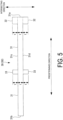
FIG. 5 is an exploded plan view of a first insulation according to the embodiment of the present disclosure. -
FIG. 6 is an exploded plan view of a second insulation according to the embodiment of the present disclosure. -
FIG. 7 is a view illustrating a combination of a first cutting tooth and a second cutting tooth included in a cutting die according to the embodiment of the present disclosure. -
FIG. 8 is a view illustrating Arrangement Example 1 of the combination of the first cutting tooth and the second cutting tooth. -
FIG. 9 is a view illustrating Arrangement Example 2 of the combination of the first cutting tooth and the second cutting tooth. -
FIG. 10 is a view illustrating Arrangement Example 3 of the combination of the first cutting tooth and the second cutting tooth. - Hereinafter, an insulation, an evaporator structure, a cutting die, and a method for producing the insulation according to an embodiment of the present disclosure will be described with reference to the drawings.
- The configuration of a vehicular air conditioning device 1 will be described first.
- As illustrated in
FIG. 1 , the vehicular air conditioning device 1 includes acasing 10 that accommodates equipment such as a fan (not illustrated) and anevaporator 20. - Note that, in the vehicular air conditioning device 1 illustrated in
FIG. 1 , thecasing 10 is partially omitted and theevaporator 20 is exposed for the sake of description. - The
casing 10 includes anair intake port 11 and anair discharge port 12. - The
air intake port 11 is an opening through which air is taken into thecasing 10 from the outside of thecasing 10. - The
air discharge port 12 is an opening for discharging air heat-exchanged by theevaporator 20 to the outside of thecasing 10. - The flow of air from the
air intake port 11 to theair discharge port 12 is formed by the fan (not illustrated). - Next, an evaporator structure including the
evaporator 20 and insulations (afirst insulation 30 and a second insulation 40) will be described. - As illustrated in
FIGS. 1 and2 , theevaporator 20 is a device (heat exchanger) for exchanging heat between a refrigerant and air, as is known. - A
pipe 22 is coupled to theevaporator 20, and theevaporator 20 is configured such that a refrigerant supplied through thepipe 22 exchanges heat with air. - As illustrated in
FIGS. 2 to 4 , theevaporator 20 according to the present embodiment has a cuboid outer shape having a rectangular shape in a front view and a predetermined depth dimension. In this case, a surface to which thepipe 22 is coupled is referred to as atop surface 21a, and respective surfaces adjacent to and orthogonal to thetop surface 21a are referred to asside surfaces side surface 21b and theside surface 21c face each other. - Sheet-like members called insulations are provided at the
top surface 21a, theside surface 21b, and theside surface 21c. Specifically, the insulations are bonded to thetop surface 21a, theside surface 21b, and theside surface 21c with, for example, glue or double-sided tapes. - The insulations are produced by performing die cutting of a sheet (insulation material 70) having wind blocking properties and made of, for example, polyethylene, polyurethane, or ethylene propylene diene rubber (EPDM). Details thereof will be described below.
- A gap formed between the
evaporator 20 and thecasing 10 is filled with the insulations and thus the insulations exert a function of blocking wind (suppressing air leakage) and firmly fixing theevaporator 20 to thecasing 10 to suppress vibration. - In the present embodiment, the insulations include a
first insulation 30 and asecond insulation 40. - As illustrated in
FIG. 5 , thefirst insulation 30 includes astrip portion 31,first wing portions 32, andsecond wing portions 33. - The
strip portion 31 is a rectangular portion including oneend 31a and anotherend 31b and extending in a predetermined direction. - Each of the
first wing portions 32 is a rectangular portion that protrudes from a corresponding one oflong sides strip portion 31 in a direction orthogonal to the predetermined direction (hereinafter, simply referred to as an "intersecting direction") at the oneend 31a of thestrip portion 31. - The
first wing portions 32 on thelong side 31c and thelong side 31d of thestrip portion 31 are paired and preferably have shapes symmetrical with respect to thestrip portion 31. - Each of the
second wing portions 33 is a rectangular portion that protrudes from the corresponding one of thelong sides strip portion 31 in the intersecting direction at a position closer to theother end 31b of thestrip portion 31 than to the oneend 31a (for example, a central portion of the strip portion 31). - The
second wing portions 33 on thelong side 31c and thelong side 31d of thestrip portion 31 are paired and preferably have shapes symmetrical with respect to thestrip portion 31. - When each
first wing portion 32 and eachsecond wing portion 33 are compared with each other, the protruding lengths from thelong side 31c and thelong side 31d of thestrip portion 31 are equal to each other, and the dimension of thefirst wing portion 32 in the predetermined direction is longer than that of thesecond wing portion 33 in the predetermined direction. - In addition, when the
strip portion 31 and eachfirst wing portion 32 are compared with each other, the dimensions in the intersecting direction (the width dimension of thestrip portion 31 and the protruding length of the first wing portion 32) are equal to each other. That is, the protruding length of one of thefirst wing portions 32, the width dimension of thestrip portion 31, and the protruding length of another of thefirst wing portions 32 have a relationship of 1:1:1. - The same also applies to the relationship between the
strip portion 31 and thesecond wing portions 33. - As illustrated in
FIG. 6 , thesecond insulation 40 is a rectangular portion extending in the predetermined direction and including oneend 41a and anotherend 41b. The respective long sides of thesecond insulation 40 are referred to aslong sides - The dimension (width dimension) of the
second insulation 40 in the intersecting direction is equal to the protruding length of thefirst wing portion 32 and the protruding length of thesecond wing portion 33. - The
first insulation 30 and thesecond insulation 40 configured as described above are disposed at theevaporator 20 as follows. - As illustrated in
FIGS. 2 to 4 , thefirst insulation 30 is disposed at thetop surface 21a and theside surface 21b of theevaporator 20. - Specifically, the
first wing portions 32, thesecond wing portions 33, and a portion of thestrip portion 31 from thefirst wing portions 32 to thesecond wing portions 33 are disposed at thetop surface 21a of theevaporator 20. In addition, a portion of thestrip portion 31 closer to theother end 31b than thesecond wing portions 33 are to theother end 31b is disposed at theside surface 21b of theevaporator 20 so as to be bent with respect to thetop surface 21a. - At this time, as illustrated in
FIG. 2 , thefirst wing portions 32 and a portion of thestrip portion 31 in the vicinity of thefirst wing portions 32 are disposed so as to wrap an end portion of thepipe 22. - As illustrated in
FIGS. 2 to 4 , thesecond insulation 40 is disposed at theside surface 21c of theevaporator 20. - In the above manner, the evaporator structure including the
evaporator 20 and the insulations (thefirst insulation 30 and the second insulation 40) is configured. - The
first insulation 30 and thesecond insulation 40 are produced by being cut out from theinsulation material 70 with a cutting die. - Specifically, by pressing a cutting tooth of the cutting die called a Thomson die against the sheet-
like insulation material 70, an insulation having a shape corresponding to the contour of the cutting tooth is punched out and produced. - The Thomson die includes a
first cutting tooth 50 following the contour of the shape of thefirst insulation 30 as illustrated inFIG. 5 . The Thomson die also includes asecond cutting tooth 60 following the contour of the shape of thesecond insulation 40 as illustrated inFIG. 6 . - Each of the
first cutting tooth 50 and thesecond cutting tooth 60 forms a closed region. The contour of the region corresponds to the contour of the shape of each of theinsulations - In the present embodiment, the shapes of the
first insulation 30 and thesecond insulation 40 and the arrangements of thefirst cutting tooth 50 and thesecond cutting tooth 60 are devised so that the two types of insulations can be produced without waste of material. - First, as a premise, the
second cutting tooth 60 is disposed between one of portions corresponding to thefirst wing portions 32 and a corresponding one of portions corresponding to thesecond wing portions 33 in thefirst cutting tooth 50, as illustrated inFIG. 7 . - At this time, one of the long sides (here, the
long side 31d) of thefirst cutting tooth 50 and one of the long sides (here, thelong side 41c) of thesecond cutting tooth 60 are shared (in other words, the cutter is shared). Moreover, as described above, the width dimension of thesecond insulation 40 is equal to the protruding length of eachfirst wing portion 32 and the protruding length of eachsecond wing portion 33. - Thus, it is possible to efficiently dispose the
second cutting tooth 60 using a region between the one of the portions corresponding to thefirst wing portions 32 and the corresponding one of the portions corresponding to thesecond wing portions 33 in thefirst cutting tooth 50. - In addition, the side corresponding to the
other end 41b of thesecond cutting tooth 60 and the side corresponding to the one of thesecond wing portions 33 of thefirst cutting tooth 50 are shared, and thus it is possible to more efficiently dispose the cutter. - Further, by devising the arrangement of the set of the
first cutting tooth 50 and thesecond cutting tooth 60 combined as described above, the two types of insulations can be produced in large quantities at a time without waste of material. - Arrangement examples thereof will be described below with reference to
FIGS. 8 to 10 . - Note that cross-hatched regions illustrated in
FIGS. 8 to 10 are remaining portions of the insulation material 70 (in other words, portions to be wasted).FIGS. 8 to 10 illustrate mere examples, and adoption of other forms is not prevented. - As illustrated in
FIG. 8 , one of portions corresponding to thefirst wing portions 32 in onefirst cutting tooth 50 is disposed between a corresponding one of portions corresponding to thefirst wing portions 32 and a corresponding one of portions corresponding to thesecond wing portions 33 in anotherfirst cutting tooth 50. - At this time, the one of the portions corresponding to the
first wing portions 32 in the onefirst cutting tooth 50 is disposed so as to share sides with the corresponding one of the portions corresponding to thefirst wing portions 32 and a portion corresponding to thestrip portion 31 in the other first cuttingtooth 50. - In addition, the
second cutting tooth 60 is disposed between the one of the portions corresponding to thefirst wing portions 32 in the onefirst cutting tooth 50 and the corresponding one of the portions corresponding to thesecond wing portions 33 in the other first cuttingtooth 50. - At this time, the
second cutting tooth 60 is disposed so as to share sides with a portion corresponding to thestrip portion 31 in the onefirst cutting tooth 50 and the portion corresponding to thestrip portion 31 in the other first cuttingtooth 50. - Furthermore, the dimensions of the
second cutting tooth 60 are set such that thesecond cutting tooth 60 shares sides with the one of the portions corresponding to thefirst wing portions 32 in the onefirst cutting tooth 50 and the corresponding one of the portions corresponding to thesecond wing portions 33 in the other first cuttingtooth 50. Thus, the entire region between the one of the portions corresponding to thefirst wing portions 32 in the onefirst cutting tooth 50 and the corresponding one of the portions corresponding to thesecond wing portions 33 in the other first cuttingtooth 50 can be used for thesecond insulation 40. That is, thesecond cutting tooth 60 is naturally formed by the arrangement of the twofirst cutting teeth 50. - The plurality of first cutting
teeth 50 are disposed in parallel in the intersecting direction according to the same rule, and furthermore, the plurality of first cuttingteeth 50 are symmetrically disposed in the predetermined direction such that portions corresponding to thesecond wing portions 33 in thefirst cutting teeth 50 face each other in a staggered manner and such that portions corresponding to thestrip portions 31 closer to the other ends 31b than thesecond wing portions 33 are to the other ends 31b are engaged with each other. Thus, the form illustrated inFIG. 8 is obtained. - As illustrated in
FIG. 9 , the plurality of first cuttingteeth 50 are disposed in parallel in the intersecting direction. - At this time, portions corresponding to the
first wing portions 32 in onefirst cutting tooth 50 and portions corresponding to thefirst wing portions 32 in anotherfirst cutting tooth 50 are disposed so as to be separated from each other by a distance equal to the width dimension of thestrip portion 31 in the intersecting direction. In addition, portions corresponding to thesecond wing portions 33 in the onefirst cutting tooth 50 and portions corresponding to thesecond wing portions 33 in the other first cuttingtooth 50 are disposed so as to be separated from each other by a distance equal to the width dimension of thestrip portion 31 in the intersecting direction. - In addition, the plurality of first cutting
teeth 50 are disposed in parallel in the intersecting direction according to the same rule, and furthermore, the plurality of first cuttingteeth 50 are symmetrically disposed in the predetermined direction such that portions corresponding to thesecond wing portions 33 in thefirst cutting teeth 50 face each other in a staggered manner so as to share sides. Thus, the form illustrated inFIG. 9 is obtained. - As illustrated in
FIG. 10 , the plurality of first cuttingteeth 50 are disposed in parallel in the intersecting direction. - At this time, portions corresponding to the
first wing portions 32 in one of the first cuttingteeth 50 and portions corresponding to thefirst wing portions 32 in another of the first cuttingteeth 50 are disposed so as to share a side. In addition, portions corresponding to thesecond wing portions 33 in the onefirst cutting tooth 50 and portions corresponding to thesecond wing portions 33 in the other first cuttingtooth 50 are disposed so as to share a side. - In addition, the plurality of first cutting
teeth 50 are disposed in parallel in the intersecting direction according to the same rule, and furthermore, the plurality of first cuttingteeth 50 are symmetrically disposed in the predetermined direction such that portions corresponding to thesecond wing portions 33 in thefirst cutting teeth 50 face each other in a staggered manner and such that portions corresponding to thestrip portions 31 closer to the other ends 31b than thesecond wing portions 33 are to the other ends 31b are engaged with each other. Thus, the form illustrated inFIG. 10 is obtained. - According to the present embodiment, the following effects are obtained.
- The
first insulation 30 includes therectangular strip portion 31 extending in the predetermined direction, the pair of rectangularfirst wing portions 32 each protruding in the intersecting direction from a corresponding one of the long sides of thestrip portion 31 at the oneend 31a of thestrip portion 31, and the pair of rectangularsecond wing portions 33 each protruding in the intersecting direction from the corresponding one of the long sides of thestrip portion 31 at a position closer to theother end 31b of thestrip portion 31 than to the oneend 31a. Thus, thefirst wing portions 32, thesecond wing portions 33, and the portion of thestrip portion 31 from thefirst wing portions 32 to thesecond wing portions 33 can be disposed at thetop surface 21a of theevaporator 20, and the portion of thestrip portion 31 closer to theother end 31b than thesecond wing portions 33 are to theother end 31b can be disposed at theside surface 21b of theevaporator 20. That is, the twosurfaces evaporator 20 can be covered with thefirst insulation 30. - When the
first insulation 30 is produced by die cutting, thesecond insulation 40 can be produced by using a region between a corresponding one of thefirst wing portions 32 and a corresponding one of thesecond wing portions 33. Thus, the two types of insulations having simple shapes can be produced without waste of material. - Further, the
first wing portions 32 and thesecond wing portions 33 are provided symmetrically with respect to thestrip portion 31. - Further, the protruding length of each
first wing portion 32 and the protruding length of eachsecond wing portion 33 are set to be equal to the width dimension of thestrip portion 31. Thus, when thesecond insulation 40 is produced using the region between the corresponding one of thefirst wing portions 32 and the corresponding one of thesecond wing portions 33, the width dimension of thestrip portion 31 of thefirst insulation 30 and the width dimension of thesecond insulation 40 can be made equal to each other. This can improve yield in producing thefirst insulation 30 and thesecond insulation 40. - In addition, the
first insulation 30 can be produced with thefirst cutting tooth 50, and thesecond insulation 40 can produced with thesecond cutting tooth 60. - Examples of the cutting die include a Thomson die.
- In addition, the
second cutting tooth 60 is disposed between the corresponding one of portions corresponding to thefirst wing portions 32 and the corresponding one of portions corresponding to thesecond wing portions 33 in thefirst cutting tooth 50, and thesecond cutting tooth 60 shares a side with a portion corresponding to thestrip portion 31 in thefirst cutting tooth 50. Thus, thesecond cutting tooth 60 can be efficiently disposed using the region between the corresponding one of thefirst wing portions 32 and the corresponding one of thesecond wing portions 33. Thus, the two types of insulations can be produced without waste of material. - In addition, by appropriately disposing the set of the
first cutting tooth 50 and thesecond cutting tooth 60, the two types of insulations can be produced without waste of material. - In addition, since a step of pressing the cutting die against the sheet-
like insulation material 70 is included, thefirst insulation 30 and thesecond insulation 40 can be produced by a simple method. - The present embodiment described above is understood as follows, for example.
- An insulation (30) according to an aspect of the present disclosure is an insulation provided at an evaporator (20) of a vehicular air conditioning device (1), the insulation including a strip portion (31) having a rectangular shape and extending in a predetermined direction, a pair of first wing portions (32), each of the pair of first wing portions having a rectangular shape and protruding in an intersecting direction orthogonal to the predetermined direction from a corresponding one of long sides of the strip portion at one end (31a) of the strip portion, and a pair of second wing portions (33), each of the pair of second wing portions having a rectangular shape and protruding in the intersecting direction orthogonal to the predetermined direction from the corresponding one of the long sides of the strip portion at a position closer to another end (31b) of the strip portion than to the one end.
- The insulation according to the present aspect includes the strip portion having a rectangular shape and extending in the predetermined direction, the pair of first wing portions, each of the pair of first wing portions having a rectangular shape and protruding in the intersecting direction orthogonal to the predetermined direction from the corresponding one of the long sides of the strip portion at the one end of the strip portion, and the pair of second wing portions, each of the pair of second wing portions having a rectangular shape and protruding in the intersecting direction orthogonal to the predetermined direction from the corresponding one of the long sides of the strip portion at the position closer to the other end of the strip portion than to the one end. Thus, the pair of first wing portions, the pair of second wing portions, and a portion of the strip portion from the pair of first wing portions to the pair of second wing portions can be disposed at a top surface (21a) of the evaporator, and a portion of the strip portion closer to the other end than the pair of second wing portions are to the other end can be disposed at a side surface (21b) of the evaporator. Thus, the two surfaces of the evaporator can be covered with this insulation.
- When the insulation is produced by die cutting, another insulation (40) to be disposed at another side surface of the evaporator can be produced using a region between a corresponding one of the pair of first wing portions and a corresponding one of the pair of second wing portions. Thus, the two types of insulations having simple shapes can be produced without waste of material.
- In an insulation according to another aspect of the present disclosure, a protruding length of one of the pair of first wing portions in the intersecting direction is set to be equal to a protruding length of another of the pair of first wing portions in the intersecting direction, and a protruding length of one of the pair of second wing portions in the intersecting direction is set to be equal to a protruding length of another of the pair of second wing portions in the intersecting direction.
- According to the insulation of the present aspect, the protruding length of the one of the pair of first wing portions in the intersecting direction is set to be equal to the protruding length of the other of the pair of first wing portions in the intersecting direction, and the protruding length of the one of the pair of second wing portions in the intersecting direction is set to be equal to the protruding length of the other of the pair of second wing portions in the intersecting direction. Thus, the pair of first wing portions and the pair of second wing portions can be provided symmetrically with respect to the strip portion.
- In an insulation according to still another aspect of the present disclosure, a protruding length of each of the pair of first wing portions from the strip portion and a protruding length of each of the pair of second wing portions from the strip portion are set to be equal to a width dimension of the strip portion in the intersecting direction.
- According to the insulation of the present aspect, the protruding length of each of the pair of first wing portions from the strip portion and the protruding length of each of the pair of second wing portions from the strip portion are set to be equal to the width dimension of the strip portion in the intersecting direction. Thus, when another insulation to be disposed at another side surface of the evaporator is produced using a region between a corresponding one of the pair of first wing portions and a corresponding one of pair of the second wing portions, the width dimension of the strip portion of the insulation can be made equal to the width dimension of the other insulation. This can improve yield in producing the insulation and the other insulation.
- An evaporator structure according to still another aspect of the present disclosure includes an evaporator including a top surface and a side surface adjacent to and orthogonal to the top surface, and the insulation according to any of the above, in which the pair of first wing portions, the pair of second wing portions, and a portion of the strip portion from the pair of first wing portions to the pair of second wing portions are disposed at the top surface of the evaporator, and a portion of the strip portion closer to the other end than the pair of second wing portions are to the other end is disposed at the side surface of the evaporator.
- The evaporator structure according to the present aspect includes the evaporator including the top surface and the side surface adjacent to and orthogonal to the top surface, and the insulation according to any of the above, in which the pair of first wing portions, the pair of second wing portions, and the portion of the strip portion from the pair of first wing portions to the pair of second wing portions are disposed at the top surface of the evaporator, and the portion of the strip portion closer to the other end than the pair of second wing portions are to the other end is disposed at the side surface of the evaporator. Thus, a predetermined two surfaces of the evaporator can be covered with the insulation having a simple shape.
- A cutting die according to still another aspect of the present disclosure includes a plurality of first cutting teeth (50), each of the plurality of first cutting teeth following a contour of a shape obtained by integrating a strip portion, a pair of first wing portions, and a pair of second wing portions, the strip portion having a rectangular shape and extending in a predetermined direction, each of the pair of first wing portions having a rectangular shape and protruding in an intersecting direction orthogonal to the predetermined direction from a corresponding one of long sides of the strip portion at one end of the strip portion, each of the pair of second wing portions having a rectangular shape and protruding in the intersecting direction orthogonal to the predetermined direction from the corresponding one of the long sides of the rectangular shape at a position closer to another end of the strip portion than to the one end, and a plurality of second cutting teeth (60), each of the plurality of second cutting teeth following a rectangular contour extending in the predetermined direction between a corresponding one of the pair of first wing portion and a corresponding one of the pair of the second wing portion.
- The cutting die according to the present aspect includes the plurality of first cutting teeth, each of the plurality of first cutting teeth following the contour of the shape obtained by integrating the strip portion, the pair of first wing portions, and the pair of second wing portions, the strip portion having a rectangular shape and extending in the predetermined direction, each of the pair of first wing portions having a rectangular shape and protruding in the intersecting direction orthogonal to the predetermined direction from the corresponding one of long sides of the strip portion at the one end of the strip portion, each of the pair of second wing portions having a rectangular shape and protruding in the intersecting direction orthogonal to the predetermined direction from the corresponding one of the long sides of the rectangular shape at the position closer to the other end of the strip portion than to the one end, and the plurality of second cutting teeth, each of the plurality of second cutting teeth following a rectangular contour extending in the predetermined direction between the corresponding one of the pair of first wing portion and the corresponding one of the pair of the second wing portion. Thus, the insulation for covering the top surface and one side surface of the evaporator can be produced with each first cutting tooth, and another insulation for covering another side surface of the evaporator can be produced with each second cutting tooth.
- Examples of the cutting die include a Thomson die.
- In addition, in a cutting die according to still another aspect of the present disclosure, each of the plurality of second cutting teeth is disposed between a corresponding one of portions corresponding to the pair of first wing portions and a corresponding one of portions corresponding to the pair of second wing portions in a corresponding one of the plurality of first cutting teeth, and each of the plurality of second cutting teeth shares a side with a portion corresponding to the strip portion in the corresponding one of the plurality of first cutting teeth.
- In the cutting die according to the present aspect, each of the plurality of second cutting teeth is disposed between the corresponding one of the portions corresponding to the pair of first wing portions and the corresponding one of the portions corresponding to the pair of second wing portions in the corresponding one of the plurality of first cutting teeth, and each of the plurality of second cutting teeth shares the side with the portion corresponding to the strip portion in the corresponding one of the plurality of first cutting teeth. Thus, each of the plurality of second cutting teeth can be efficiently disposed using a region between the corresponding one of the pair of first wing portions and the corresponding one of the pair of second wing portions. Thus, the two types of insulations can be produced without waste of material.
- In a cutting die according to still another aspect of the present disclosure, one of portions corresponding to the pair of first wing portions in one of the plurality of first cutting teeth is disposed between a corresponding one of portions corresponding to the pair of first wing portions and a corresponding one of portions corresponding to the pair of second wing portions in another of the plurality of first cutting teeth, and the one of the portions corresponding to the pair of first wing portions in the one of the plurality of first cutting teeth shares sides with the corresponding one of the portions corresponding to the pair of first wing portions and a portion corresponding to the strip portion in the other of the plurality of first cutting teeth, and one of the plurality of second cutting teeth is disposed between the one of the portions corresponding to the pair of first wing portions in the one of the plurality of first cutting teeth and the corresponding one of the portions corresponding to the pair of second wing portions in the other of the plurality of first cutting teeth, and the one of the plurality of second cutting teeth shares sides with a portion corresponding to the strip portion in the one of the plurality of first cutting teeth and the portion corresponding to the strip portion in the other of the plurality of first cutting teeth.
- According to the cutting die of the present aspect, the plurality of first cutting teeth and the plurality of second cutting teeth can be efficiently disposed. Thus, the two types of insulations can be produced without waste of material.
- In a cutting die according to still another aspect of the present disclosure, one of the plurality of first cutting teeth and another of the plurality of first cutting teeth are disposed in parallel in the intersecting direction, and one of the plurality of second cutting teeth is disposed between a corresponding one of portions corresponding to the pair of first wing portions and a corresponding one of portions corresponding to the pair of second wing portions in the one of the plurality of first cutting teeth or the other of the plurality of first cutting teeth, and the one of the plurality of second cutting teeth shares a side with the portion corresponding to the strip portion in the one of the plurality of first cutting teeth or the other of the plurality of first cutting teeth.
- According to the cutting die of the present aspect, the plurality of first cutting teeth and the plurality of second cutting teeth can be efficiently disposed. Thus, the two types of insulations can be produced without waste of material.
- In a cutting die according to still another aspect of the present disclosure, the portions corresponding to the pair of first wing portions in the one of the plurality of first cutting teeth and the portions corresponding to the pair of first wing portions in the other of the plurality of first cutting teeth are separated from each other by a distance equal to a width dimension of the strip portion in the intersecting direction, and the portions corresponding to the pair of second wing portions in the one of the plurality of first cutting teeth and the portions corresponding to the pair of second wing portions in the other of the plurality of first cutting teeth are separated from each other by the distance equal to the width dimension of the strip portion in the intersecting direction.
- According to the cutting die of the present aspect, the plurality of first cutting teeth and the plurality of second cutting teeth can be efficiently disposed. Thus, the two types of insulations can be produced without waste of material.
- In a cutting die according to still another aspect of the present disclosure, the portions corresponding to the pair of first wing portions in the one of the plurality of first cutting teeth share a side with the portions corresponding to the pair of first wing portions in the other of the plurality of first cutting teeth, and the portions corresponding to the pair of second wing portions in the one of the plurality of first cutting teeth share a side with the portions corresponding to the pair of second wing portions in the other of the plurality of first cutting teeth.
- According to the cutting die of the present aspect, the plurality of first cutting teeth and the plurality of second cutting teeth can be efficiently disposed. Thus, the two types of insulations can be produced without waste of material.
- A method for producing an insulation according to still another aspect of the present disclosure includes pressing the cutting die according to any of the above against a sheet-like insulation material (70).
- The method for producing the insulation of the present aspect includes pressing the cutting die according to any of the above against the sheet-like insulation material. Thus, the insulation can be produced by a simple method.
-
- 1 Vehicular air conditioning device
- 10 Casing
- 11 Air intake port
- 12 Air discharge port
- 20 Evaporator
- 21a Top surface
- 21b Side surface
- 21c Side surface
- 22 Pipe
- 30 First insulation (insulation)
- 31 Strip portion
- 31a One end
- 31b Another end
- 31c, 31d Long side
- 32 First wing portion
- 33 Second wing portion
- 40 Second insulation (another insulation)
- 41a One end
- 41b Another end
- 41c, 41d Long side
- 50 First cutting tooth
- 60 Second cutting tooth
- 70 Insulation material
Claims (11)
- An insulation provided at an evaporator of a vehicular air conditioning device, the insulation comprising:a strip portion having a rectangular shape and extending in a predetermined direction;a pair of first wing portions, each of the pair of first wing portions having a rectangular shape and protruding in an intersecting direction orthogonal to the predetermined direction from a corresponding one of long sides of the strip portion at one end of the strip portion; anda pair of second wing portions, each of the pair of second wing portions having a rectangular shape and protruding in the intersecting direction orthogonal to the predetermined direction from the corresponding one of the long sides of the strip portion at a position closer to another end of the strip portion than to the one end.
- The insulation according to claim 1, whereina protruding length of one of the pair of first wing portions in the intersecting direction is set to be equal to a protruding length of another of the pair of first wing portions in the intersecting direction, anda protruding length of one of the pair of second wing portions in the intersecting direction is set to be equal to a protruding length of another of the pair of second wing portions in the intersecting direction.
- The insulation according to claim 2, wherein
a protruding length of each of the pair of first wing portions from the strip portion and a protruding length of each of the pair of second wing portions from the strip portion are set to be equal to a width dimension of the strip portion in the intersecting direction. - An evaporator structure comprising:an evaporator including a top surface and a side surface adjacent to and orthogonal to the top surface; andthe insulation according to any of claims 1 to 3, whereinthe pair of first wing portions, the pair of second wing portions, and a portion of the strip portion from the pair of first wing portions to the pair of second wing portions are disposed at the top surface of the evaporator, anda portion of the strip portion closer to the other end than the pair of second wing portions are to the other end is disposed at the side surface of the evaporator.
- A cutting die comprising:a plurality of first cutting teeth, each of the plurality of first cutting teeth following a contour of a shape obtained by integrating a strip portion, a pair of first wing portions, and a pair of second wing portions, the strip portion having a rectangular shape and extending in a predetermined direction, each of the pair of first wing portions having a rectangular shape and protruding in an intersecting direction orthogonal to the predetermined direction from a corresponding one of long sides of the strip portion at one end of the strip portion, each of the pair of second wing portions having a rectangular shape and protruding in the intersecting direction orthogonal to the predetermined direction from the corresponding one of the long sides of the rectangular shape at a position closer to another end of the strip portion than to the one end; anda plurality of second cutting teeth, each of the plurality of second cutting teeth following a rectangular contour extending in the predetermined direction between a corresponding one of the pair of first wing portion and a corresponding one of the pair of the second wing portion.
- The cutting die according to claim 5, whereineach of the plurality of second cutting teeth is disposed between a corresponding one of portions corresponding to the pair of first wing portions and a corresponding one of portions corresponding to the pair of second wing portions in a corresponding one of the plurality of first cutting teeth, andeach of the plurality of second cutting teeth shares a side with a portion corresponding to the strip portion in the corresponding one of the plurality of first cutting teeth.
- The cutting die according to claim 6, whereinone of portions corresponding to the pair of first wing portions in one of the plurality of first cutting teeth is disposed between a corresponding one of portions corresponding to the pair of first wing portions and a corresponding one of portions corresponding to the pair of second wing portions in another of the plurality of first cutting teeth,the one of the portions corresponding to the pair of first wing portions in the one of the plurality of first cutting teeth shares sides with the corresponding one of the portions corresponding to the pair of first wing portions and a portion corresponding to the strip portion in the other of the plurality of first cutting teeth,one of the plurality of second cutting teeth is disposed between the one of the portions corresponding to the pair of first wing portions in the one of the plurality of first cutting teeth and the corresponding one of the portions corresponding to the pair of second wing portions in the other of the plurality of first cutting teeth, andthe one of the plurality of second cutting teeth shares sides with a portion corresponding to the strip portion in the one of the plurality of first cutting teeth and the portion corresponding to the strip portion in the other of the plurality of first cutting teeth.
- The cutting die according to claim 6, whereinone of the plurality of first cutting teeth and another of the plurality of first cutting teeth are disposed in parallel in the intersecting direction,one of the plurality of second cutting teeth is disposed between a corresponding one of portions corresponding to the pair of first wing portions and a corresponding one of portions corresponding to the pair of second wing portions in the one of the plurality of first cutting teeth or the other of the plurality of first cutting teeth, andthe one of the plurality of second cutting teeth shares a side with the portion corresponding to the strip portion in the one of the plurality of first cutting teeth or the other of the plurality of first cutting teeth.
- The cutting die according to claim 8, whereinthe portions corresponding to the pair of first wing portions in the one of the plurality of first cutting teeth and the portions corresponding to the pair of first wing portions in the other of the plurality of first cutting teeth are separated from each other by a distance equal to a width dimension of the strip portion in the intersecting direction, andthe portions corresponding to the pair of second wing portions in the one of the plurality of first cutting teeth and the portions corresponding to the pair of second wing portions in the other of the plurality of first cutting teeth are separated from each other by the distance equal to the width dimension of the strip portion in the intersecting direction.
- The cutting die according to claim 8, whereinthe portions corresponding to the pair of first wing portions in the one of the plurality of first cutting teeth share a side with the portions corresponding to the pair of first wing portions in the other of the plurality of first cutting teeth, andthe portions corresponding to the pair of second wing portions in the one of the plurality of first cutting teeth share a side with the portions corresponding to the pair of second wing portions in the other of the plurality of first cutting teeth.
- A method for producing an insulation, the method comprising:
pressing the cutting die according to any of claims 5 to 10 against a sheet-like insulation material.
Applications Claiming Priority (2)
| Application Number | Priority Date | Filing Date | Title |
|---|---|---|---|
| JP2021126439A JP2023021525A (en) | 2021-08-02 | 2021-08-02 | Insulation, evaporator structure and trimming die, and manufacturing method of insulation |
| PCT/JP2022/021970 WO2023013220A1 (en) | 2021-08-02 | 2022-05-30 | Insulation, evaporator structure, cutting die, and method for producing insulation |
Publications (2)
| Publication Number | Publication Date |
|---|---|
| EP4364984A1 true EP4364984A1 (en) | 2024-05-08 |
| EP4364984A4 EP4364984A4 (en) | 2024-11-13 |
Family
ID=85155705
Family Applications (1)
| Application Number | Title | Priority Date | Filing Date |
|---|---|---|---|
| EP22852648.9A Withdrawn EP4364984A4 (en) | 2021-08-02 | 2022-05-30 | INSULATION, EVAPORATOR STRUCTURE, CUTTING PLATE AND METHOD FOR PRODUCING THE INSULATION |
Country Status (3)
| Country | Link |
|---|---|
| EP (1) | EP4364984A4 (en) |
| JP (1) | JP2023021525A (en) |
| WO (1) | WO2023013220A1 (en) |
Families Citing this family (1)
| Publication number | Priority date | Publication date | Assignee | Title |
|---|---|---|---|---|
| CN119682483B (en) * | 2025-01-08 | 2025-12-16 | 上汽通用五菱汽车股份有限公司 | Heat exchanger for air conditioner, thermal management system and vehicle |
Family Cites Families (9)
| Publication number | Priority date | Publication date | Assignee | Title |
|---|---|---|---|---|
| JP3489526B2 (en) * | 2000-02-23 | 2004-01-19 | 株式会社デンソー | Seal structure of heat exchanger |
| JP4779858B2 (en) * | 2006-07-27 | 2011-09-28 | 株式会社デンソー | Heat exchanger |
| KR101380709B1 (en) * | 2007-09-05 | 2014-04-02 | 한라비스테온공조 주식회사 | Manufacturing method of heat exchanger |
| JP5075619B2 (en) * | 2007-12-27 | 2012-11-21 | 花王株式会社 | Absorbent articles |
| US10202017B2 (en) * | 2013-11-26 | 2019-02-12 | Keihin Corporation | Vehicular air-conditioning device |
| DE102015208662A1 (en) * | 2014-05-14 | 2015-11-19 | Denso Thermal Systems S.P.A. | Vibration damping system for a heat exchanger of a vehicle |
| JP6350373B2 (en) * | 2015-04-17 | 2018-07-04 | 株式会社デンソー | Evaporator |
| JP6804269B2 (en) * | 2016-11-18 | 2020-12-23 | 三菱重工サーマルシステムズ株式会社 | Heat exchanger |
| DE102017128394B4 (en) * | 2017-11-30 | 2019-10-17 | Held-Systems Gmbh | Method for cutting cut parts and device for cutting |
-
2021
- 2021-08-02 JP JP2021126439A patent/JP2023021525A/en active Pending
-
2022
- 2022-05-30 WO PCT/JP2022/021970 patent/WO2023013220A1/en not_active Ceased
- 2022-05-30 EP EP22852648.9A patent/EP4364984A4/en not_active Withdrawn
Also Published As
| Publication number | Publication date |
|---|---|
| WO2023013220A1 (en) | 2023-02-09 |
| EP4364984A4 (en) | 2024-11-13 |
| JP2023021525A (en) | 2023-02-14 |
Similar Documents
| Publication | Publication Date | Title |
|---|---|---|
| US10247482B2 (en) | Bent heat exchanger and method for bending the heat exchanger | |
| CN101772851B (en) | Battery housing having an attached fluid flow guiding unit | |
| EP2131133A1 (en) | Heat exchange element | |
| EP2945216A1 (en) | Assembled battery restraint, assembled battery restraining member, and battery | |
| AU2003275690B2 (en) | Outdoor unit of refrigerator, and electrical equipment box of outdoor unit | |
| JP3100287B2 (en) | Air conditioner | |
| JP6180262B2 (en) | Air conditioner indoor unit | |
| WO2023013220A1 (en) | Insulation, evaporator structure, cutting die, and method for producing insulation | |
| JP5586571B2 (en) | Air conditioner outdoor unit | |
| CN213599858U (en) | Heat exchange core and heat exchanger | |
| CN100470172C (en) | Air conditioner heat exchanger | |
| JP2017120134A (en) | Heat exchanger | |
| CN103776151B (en) | Air conditioner | |
| JP3382770B2 (en) | Heat exchanger | |
| CN203083026U (en) | Indoor unit | |
| US20140367076A1 (en) | Heat exchanger for vehicle air-conditioner and vehicle air-conditioner | |
| CN209320233U (en) | The rectangle box-frame of hot runner system temperature control box | |
| JP6678745B2 (en) | Air conditioner indoor unit | |
| WO2024157344A1 (en) | Outdoor unit of refrigeration cycle device and heat exchanger protection panel | |
| CN119921039B (en) | Battery assembly, battery pack and power utilization system | |
| CN113883713B (en) | Condenser components and heat exchange equipment | |
| CN204313410U (en) | The off-premises station of air conditioner | |
| JP5206815B2 (en) | Heat exchanger | |
| CN109203378A (en) | The rectangle box-frame of hot runner system temperature control box | |
| CN203893391U (en) | Air conditioner |
Legal Events
| Date | Code | Title | Description |
|---|---|---|---|
| STAA | Information on the status of an ep patent application or granted ep patent |
Free format text: STATUS: THE INTERNATIONAL PUBLICATION HAS BEEN MADE |
|
| PUAI | Public reference made under article 153(3) epc to a published international application that has entered the european phase |
Free format text: ORIGINAL CODE: 0009012 |
|
| STAA | Information on the status of an ep patent application or granted ep patent |
Free format text: STATUS: REQUEST FOR EXAMINATION WAS MADE |
|
| 17P | Request for examination filed |
Effective date: 20240202 |
|
| AK | Designated contracting states |
Kind code of ref document: A1 Designated state(s): AL AT BE BG CH CY CZ DE DK EE ES FI FR GB GR HR HU IE IS IT LI LT LU LV MC MK MT NL NO PL PT RO RS SE SI SK SM TR |
|
| DAV | Request for validation of the european patent (deleted) | ||
| DAX | Request for extension of the european patent (deleted) | ||
| A4 | Supplementary search report drawn up and despatched |
Effective date: 20241014 |
|
| RIC1 | Information provided on ipc code assigned before grant |
Ipc: B60H 1/32 20060101ALI20241008BHEP Ipc: B60H 1/00 20060101AFI20241008BHEP |
|
| STAA | Information on the status of an ep patent application or granted ep patent |
Free format text: STATUS: THE APPLICATION HAS BEEN WITHDRAWN |
|
| 18W | Application withdrawn |
Effective date: 20250410 |