EP4364976A1 - Tire - Google Patents
Tire Download PDFInfo
- Publication number
- EP4364976A1 EP4364976A1 EP21948486.2A EP21948486A EP4364976A1 EP 4364976 A1 EP4364976 A1 EP 4364976A1 EP 21948486 A EP21948486 A EP 21948486A EP 4364976 A1 EP4364976 A1 EP 4364976A1
- Authority
- EP
- European Patent Office
- Prior art keywords
- tire
- projecting portion
- communication device
- rubber
- width direction
- Prior art date
- Legal status (The legal status is an assumption and is not a legal conclusion. Google has not performed a legal analysis and makes no representation as to the accuracy of the status listed.)
- Granted
Links
Images

Classifications
-
- B—PERFORMING OPERATIONS; TRANSPORTING
- B60—VEHICLES IN GENERAL
- B60C—VEHICLE TYRES; TYRE INFLATION; TYRE CHANGING; CONNECTING VALVES TO INFLATABLE ELASTIC BODIES IN GENERAL; DEVICES OR ARRANGEMENTS RELATED TO TYRES
- B60C13/00—Tyre sidewalls; Protecting, decorating, marking, or the like, thereof
- B60C13/02—Arrangement of grooves or ribs
-
- B—PERFORMING OPERATIONS; TRANSPORTING
- B60—VEHICLES IN GENERAL
- B60C—VEHICLE TYRES; TYRE INFLATION; TYRE CHANGING; CONNECTING VALVES TO INFLATABLE ELASTIC BODIES IN GENERAL; DEVICES OR ARRANGEMENTS RELATED TO TYRES
- B60C19/00—Tyre parts or constructions not otherwise provided for
-
- B—PERFORMING OPERATIONS; TRANSPORTING
- B60—VEHICLES IN GENERAL
- B60C—VEHICLE TYRES; TYRE INFLATION; TYRE CHANGING; CONNECTING VALVES TO INFLATABLE ELASTIC BODIES IN GENERAL; DEVICES OR ARRANGEMENTS RELATED TO TYRES
- B60C15/00—Tyre beads, e.g. ply turn-up or overlap
- B60C15/06—Flipper strips, fillers, or chafing strips and reinforcing layers for the construction of the bead
- B60C2015/0614—Flipper strips, fillers, or chafing strips and reinforcing layers for the construction of the bead characterised by features of the chafer or clinch portion, i.e. the part of the bead contacting the rim
-
- B—PERFORMING OPERATIONS; TRANSPORTING
- B60—VEHICLES IN GENERAL
- B60C—VEHICLE TYRES; TYRE INFLATION; TYRE CHANGING; CONNECTING VALVES TO INFLATABLE ELASTIC BODIES IN GENERAL; DEVICES OR ARRANGEMENTS RELATED TO TYRES
- B60C19/00—Tyre parts or constructions not otherwise provided for
- B60C2019/004—Tyre sensors other than for detecting tyre pressure
Definitions
- the present disclosure relates to a tire.
- JP 2020-179827 A discloses a tire in which an RF tag is provided between the rim strip rubber and sidewall rubber of the tire.
- a tire according to the present disclosure comprises: a projecting portion that projects outward in a tire width direction on a tire outer circumferential surface of a sidewall portion; and a communication device embedded in the projecting portion.
- the “tire radial inner side” denotes the side closer to the rotation axis of the tire in the tire radial direction
- the “tire radial outer side” denotes the side farther from the rotation axis of the tire in the tire radial direction
- the “tire widthwise inner side” denotes the side closer to the tire equatorial plane CL in the tire width direction
- the “tire widthwise outer side” denotes the side farther from the tire equatorial plane CL in the tire width direction.
- the "reference state” is a state in which the tire is attached to a rim of a wheel, which is an applicable rim, filled to a prescribed internal pressure, and placed under no load. Both ends in the tire width direction of the contact patch that is in contact with the road surface in a state in which the tire is attached to a rim of a wheel, which is an applicable rim, filled to a prescribed internal pressure, and placed under a prescribed load are referred to as ground contact edges E.
- ground contact edges E ground contact edges
- the "applicable rim” is an approved rim ("measuring rim” in ETRTO (European Tyre and Rim Technical Organization) Standards Manual, "design rim” in TRA (Tire and Rim Association, Inc.) Year Book) in applicable size that is described or will be described in the future in an effective industrial standard in areas where tires are produced and used, such as JATMA (Japan Automobile Tyre Manufacturers Association) Year Book in Japan, ETRTO Standards Manual in Europe, or TRA Year Book in the United States.
- the "applicable rim” denotes a rim whose width corresponds to the bead width of the tire.
- the “applicable rim” includes not only current size but also a size that may be included in the industrial standard in the future.
- An example of the "size that will be described in the future” is the size described as "future developments" in ETRTO Standards Manual 2013.
- the "prescribed internal pressure” denotes the air pressure (maximum air pressure) corresponding to the maximum load capability of a single wheel in applicable size and ply rating described in the industrial standard such as JATMA Year Book.
- the "prescribed internal pressure” denotes the air pressure (maximum air pressure) corresponding to the maximum load capability defined for each vehicle on which the tire is mounted.
- the "prescribed load” denotes the load corresponding to the maximum load capability of a single wheel in applicable size and ply rating described in the industrial standard.
- the "prescribed load” denotes the load corresponding to the maximum load capability defined for each vehicle on which the tire is mounted.
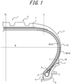
- a tire 1 according to Embodiment 1 of the present disclosure will be described below with reference to FIG. 1 .
- FIG. 1 is a partial cross-sectional view of the tire 1 according to Embodiment 1 of the present disclosure, taken along the tire width direction.
- FIG. 1 illustrates the tire 1 in the reference state in which the tire 1 is attached to a rim R of a wheel, which is the applicable rim, filled to the prescribed internal pressure, and placed under no load.
- the tire 1 includes a pair of bead portions 2, a pair of sidewall portions 3, and a tread portion 4. Each sidewall portion 3 extends between the tread portion 4 and the corresponding bead portion 2.
- the sidewall portion 3 may be, for example, a portion between the tire radial outer end of the bead core 5 and the ground contact edge E.
- the sidewall portion 3 may be a portion between the tire radial outer end of the bead filler 8 and the ground contact edge E.
- the sidewall portion 3 of the tire 1 has a projecting portion 3A that projects outward in the tire width direction from the tire outer circumferential surface.
- a communication device 11 is embedded in the projecting portion 3A, which will be described in detail later.
- the projecting portion 3A has an annular shape extending in the tire circumferential direction on the tire outer circumferential surface.
- the size of the projecting portion 3A may be set to any size depending on, for example, the size or intended use of the tire 1 or the communication device 11.
- the length of a virtual line L connecting the tire radial inner end and tire radial outer end of the projecting portion 3A may be 10 mm to 60 mm.
- the length of the virtual line L may be 15 mm to 45 mm.
- the maximum length of the projecting portion 3A in the projecting direction may be, for example, 15 mm to 40 mm.
- the projecting direction of the projecting portion 3A denotes a direction perpendicular to the virtual line L connecting the tire radial inner end and tire radial outer end of the projecting portion 3A in a cross-sectional view in the tire width direction as indicated by the broken line in FIG. 1 .
- the tire widthwise inner side in the projecting direction of the projecting portion 3A is referred to as the “inner side in the projecting direction”
- the tire widthwise outer side in the projecting direction of the projecting portion 3A is referred to as the “outer side in the projecting direction”.
- the width of the projecting portion 3A decreases toward the outer side in the projecting direction of the projecting portion 3A, in a cross-sectional view in the tire width direction.
- the cross-sectional shape of the projecting portion 3A in the tire width direction is approximately triangular.
- the cross-sectional shape of the projecting portion 3A in the tire width direction is, however, not limited to a triangle, and may be a trapezoid, a shape with a rounded tip, or the like. In this way, the amount of rubber material used to form the projecting portion 3A can be reduced to thus reduce the weight and production cost of the tire 1.
- the tire 1 may be asymmetrical with respect to the tire equatorial plane CL.
- the tire 1 may be asymmetrical with respect to the tire equatorial plane CL.
- only one of the pair of sidewall portions 3 may have the projecting portion 3A.
- the tire 1 includes a pair of bead cores 5 located in the bead portions 2, a carcass 6 composed of one or more plies toroidally extending between the pair of bead cores 5, and a belt 7 composed of one or more belt layers located on the tire radial outer side of the crown region of the carcass 6.
- Each bead core 5 is composed of an annular cable bead extending in the tire circumferential direction.
- the cross-sectional shape of the bead core 5 in a plane orthogonal to its extending direction (cross-sectional shape in the tire width direction) is circular or approximately circular.
- the cross-sectional shape of the bead core 5 in the tire width direction may be, however, any shape such as a quadrangle or a hexagon.
- the cable bead is formed by coating a high carbon steel wire with rubber, for example.
- a bead filler 8 made of a rubber material or the like is provided on the tire radial outer side of the bead core 5. Alternatively, the bead filler 8 in the tire 1 may be omitted.
- the carcass 6 is composed of one or more plies (one ply in this embodiment) toroidally extending between the pair of bead cores 5.
- the ply is formed by coating an organic fiber cord such as a nylon cord with rubber, for example.
- the ends of the carcass 6 are locked by the bead cores 5.
- the carcass 6 includes a carcass body portion 6A located between the bead cores 5, and carcass folded portions 6B each folded back from inside to outside in the tire width direction around the corresponding bead core 5.
- the carcass folded portion 6B terminates near the position of the tire maximum width W in the reference state.
- the "position of the tire maximum width W" is the position at which the widthwise length of the tire 1 in a cross section in the tire width direction is longest.
- the carcass folded portion 6B may, however, have any length.
- the carcass 6 may have a structure in which the carcass folded portion 6B is folded back from outside to inside in the tire width direction around the bead core 5 or a structure in which the carcass folded portion 6B is wound around the bead core 5, or may include no carcass folded portion 6B.
- the belt 7 is located on the tire radial outer side of the crown region of the carcass 6.
- the belt 7 is composed of one or more belt layers (two belt layers in this embodiment) laminated in the tire radial direction in the tire equatorial plane CL.
- the belt 7 is provided so as to cover the carcass 6 from the tire radial outer side in the tread portion 4.
- the belt 7 extends to a position that is outward in the tire width direction from the ground contact edge E, centering on the tire equatorial plane CL.
- the belt 7 may extend to a position that is inward in the tire width direction from the ground contact edge E.
- the tire 1 further includes rubber chafers 9.
- Each rubber chafer 9 is provided so as to cover the bead core 5 and the carcass 6 from the tire radial inner side and the tire widthwise outer side.
- the rubber chafer 9 terminates at a position between the tire radial outer end of the bead filler 8 and the tire radial outer end of the carcass folded portion 6B.
- the rubber chafer 9 may, however, have any length.
- a side rubber 10 is located on the tire radial outer side of the rubber chafer 9 so as to cover the tire widthwise outer side of the carcass 6.
- the tire radial inner end of the side rubber 10 is located between the carcass 6 and the rubber chafer 9 in the tire width direction.
- the tire radial inner end of the side rubber 10 may be located outward in the tire radial direction from the rubber chafer 9, or located outward in the tire width direction from the rubber chafer 9.
- the rubber chafer 9 may be made of a rubber material higher in strength than the side rubber 10.
- the rubber chafer 9 may be made of a rubber material higher in carbon content than the side rubber 10.
- the tire 1 is provided with the communication device 11.
- the communication device 11 performs wireless communication.
- the communication device 11 is a radio frequency (RF) tag.
- the RF tag is also referred to as a radio frequency identification (RFID) tag.
- the communication device 11 includes an integrated circuit (IC) chip including a controller and a storage, and one or more antennas connected to the IC chip.
- the IC chip may store any information about the tire 1, such as the identification information and manufacturing date of the tire 1.
- the communication device 11 may have a long shape as a whole, with two linearly, wavily, or spirally extending antennas extending in opposite directions from the IC chip. Each antenna, however, may have any shape and may be located within the IC chip.
- the IC chip may be operated by induced electromotive force generated by electromagnetic waves received by the one or more antennas. That is, the communication device 11 may be a passive type communication device. Alternatively, the communication device 11 may further include a battery and be capable of communication by generating electromagnetic waves using its own power. That is, the communication device 11 may be an active type communication device.
- the communication device 11 is embedded in the projecting portion 3A. Since the projecting portion 3A projects outward in the tire width direction from the tire outer circumferential surface, when a load is applied to the tire 1, the projecting portion 3Ais less likely to be subjected to the load and deformed. Providing the communication device 11 in such a projecting portion 3A makes the communication device 11 more failure-resistant. Moreover, as a result of the communication device 11 being provided in the projecting portion 3A, when the communication device 11 communicates with an electronic device located outward in the tire width direction from the tire 1, the other parts of the tire 1 are less likely to interfere with the communication by the communication device 11. This improves the usefulness of the communication device 11 provided in the tire 1.
- the communication device 11 may be embedded in the projecting portion 3A so that the longitudinal direction of the communication device 11 will be approximately parallel to the circumferential direction of the tire 1.
- the projecting portion 3A includes at least part of the rubber chafer 9 and at least part of the side rubber 10.
- the communication device 11 is embedded at the boundary between the at least part of the rubber chafer 9 and the at least part of the side rubber 10.
- the rubber chafer 9 is in contact with the communication device 11 from at least one of the tire radial inner side and tire widthwise inner side of the communication device 11, and the side rubber 10 is in contact with the communication device 11 from at least one of the tire radial outer side and tire widthwise outer side of the communication device 11.
- the durability of the communication device 11 embedded in the tire 1 is improved as a result of the communication device 11 being supported by the rubber chafer 9 higher in strength than the side rubber 10, and the communicability of the communication device 11 embedded in the tire 1 is improved as a result of the communication device 11 being covered with the side rubber 10 higher in conductivity than the rubber chafer 9.
- the projecting portion 3A In the reference state, the projecting portion 3A is located inward in the tire radial direction from the position of the tire maximum width W. The projecting portion 3A is therefore less likely to hit obstacles such as curbstones or pebbles. The probability of a failure of the communication device 11 embedded in the projecting portion 3A can thus be reduced.
- the projecting portion 3A projects to a position that is outward in the tire width direction from the tire widthwise outer end of the rim R which is the applicable rim.
- the projecting portion 3A prevents the rim R on which the tire 1 is mounted from coming into contact with a rim on which another tire is mounted.
- the projecting portion 3A also keeps the rim R from hitting obstacles such as curbstones or pebbles.
- the projecting portion 3A can thus function as a rim guard to prevent the rim R from being damaged.
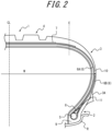
- FIG. 2 is a partial cross-sectional view of the tire 1 according to Embodiment 2 of the present disclosure taken along the tire width direction.
- FIG. 2 illustrates the tire 1 in the reference state in which the tire 1 is attached to a rim R of a wheel, which is the applicable rim, filled to the prescribed internal pressure, and placed under no load.
- Embodiment 2 differs from Embodiment 1 in that the projecting portion 3A provided in the sidewall portion 3 is made of a different rubber material from the other portions adjacent to the projecting portion 3A in the sidewall portion 3.
- Embodiment 2 will be described below, focusing on the differences from Embodiment 1.
- the parts having the same structures as those in Embodiment 1 are given the same reference signs.
- the sidewall portion 3 of the tire 1 has the projecting portion 3A that projects outward in the tire width direction from the tire outer circumferential surface, as in Embodiment 1.
- the communication device 11 is embedded in the projecting portion 3A.
- the projecting portion 3A is made of a different rubber material from the other portions adjacent to the projecting portion 3A in the sidewall portion 3.
- the rubber material forming the projecting portion 3A can be selected depending on the intended use of the tire 1 and the communication device 11.
- the projecting portion 3A is made of a different rubber material from the rubber chafer 9 extending from the bead portion 2 to the sidewall portion 3 and the side rubber 10 mainly forming the sidewall portion 3.
- the projecting portion 3A may be made of a rubber material having high strength as a result of having higher carbon content than the other portions, in order to strengthen the projecting portion 3A against contact with obstacles, cutting, etc.
- the durability of the communication device 11 embedded in the tire 1 can thus be improved. This is useful when the tire 1 is mounted on a vehicle that is intended to run on rough roads.
- the projecting portion 3A may be made of a rubber material having high conductivity as a result of having lower carbon content than the other portions. The communicability of the communication device 11 embedded in the tire 1 can thus be improved.
- the communication device 11 is embedded at the interface with the rubber material forming the other portions.
- the communication device 11 can be stably installed in the tire 1, with it being possible to improve the productivity of the tire 1.
- FIG. 3 is a partial cross-sectional view of the tire 1 according to Embodiment 3 of the present disclosure taken along the tire width direction.
- FIG. 3 illustrates the tire 1 in the reference state in which the tire 1 is attached to a rim R of a wheel, which is the applicable rim, filled to the prescribed internal pressure, and placed under no load.
- Embodiment 3 differs from Embodiments 1 and 2 in that the projecting portion 3A is located outward in the tire radial direction from the position of the tire maximum width W in the sidewall portion 3.
- Embodiment 3 will be described below, focusing on the differences from Embodiments 1 and 2.
- the parts having the same structures as those in Embodiments 1 and 2 are given the same reference signs.
- the sidewall portion 3 of the tire 1 has the projecting portion 3A that projects outward in the tire width direction from the tire outer circumferential surface, as in Embodiments 1 and 2.
- the communication device 11 is embedded in the projecting portion 3A.
- the projecting portion 3A may be made of the same rubber material as the other portions adjacent to the projecting portion 3A in the sidewall portion 3.
- the projecting portion 3A may be made of the same rubber material as the side rubber 10 that mainly forms the sidewall portion 3.
- the projecting portion 3A may be made of a different rubber material from the other portions adjacent to the projecting portion 3A in the sidewall portion 3, as in Embodiment 2.
- the projecting portion 3A may be made of a different rubber material from the side rubber 10 that mainly forms the sidewall portion 3.
- the projecting portion 3A is located outward in the tire radial direction from the position of the tire maximum width W.
- the communication device 11 communicates with an electronic device located outward in the tire radial direction from the tire 1, such as a road surface, the other parts of the tire 1 are less likely to interfere with the communication by the communication device 11. This improves the usefulness of the communication device 11 provided in the tire 1.
- the tire 1 comprises: the projecting portion 3A that projects outward in the tire width direction on the tire outer circumferential surface of the sidewall portion 3; and the communication device 11 embedded in the projecting portion 3A.
- the communication device 11 is embedded in the projecting portion 3A that is less likely to be deformed when a load is applied to the tire 1, the communication device 11 is more failure-resistant.
- the communication device 11 being provided in the projecting portion 3A, when the communication device 11 communicates with an electronic device located outside the tire 1, the other parts of the tire 1 are less likely to interfere with the communication by the communication device 11. This improves the usefulness of the communication device 11 provided in the tire 1.
- the projecting portion 3A includes at least part of the rubber chafer 9 and at least part of the side rubber 10, and the communication device 11 is embedded at the boundary between the at least part of the rubber chafer 9 and the at least part of the side rubber 10.
- the communication device 11 can be stably installed in the tire 1, with it being possible to improve the productivity of the tire 1.
- the projecting portion 3A is made of a different rubber material from any other portion adjacent to the projecting portion 3A in the sidewall portion 3.
- the rubber material forming the projecting portion 3A can be selected depending on the intended use of the tire 1 and the communication device 11. This further improves the usefulness of the communication device 11 provided in the tire 1.
- the width of the projecting portion 3A decreases toward the outer side in the projecting direction of the projecting portion 3A in a cross-sectional view in the tire width direction.
- the amount of rubber material used to form the projecting portion 3A can be reduced to thus reduce the weight and production cost of the tire 1.
- the projecting portion 3A is located inward in the tire radial direction from the position of the tire maximum width W.
- the projecting portion 3A is less likely to hit obstacles such as curbstones or pebbles. The probability of a failure of the communication device 11 can thus be reduced.
- the projecting portion 3A projects to a position that is outward in the tire width direction from the tire widthwise outer end of the applicable rim.
- the projecting portion 3A can function as a rim guard to prevent the rim R from being damaged.
- the projecting portion 3A is located outward in the tire radial direction from the position of the tire maximum width W.
- the communication device 11 communicates with an electronic device located outward in the tire radial direction from the tire 1, such as a road surface, the other parts of the tire 1 are less likely to interfere with the communication by the communication device 11. This further improves the usefulness of the communication device 11 provided in the tire 1.
- the structures, functions, etc. included in each embodiment may be rearranged without logical inconsistency.
- the structures, functions, etc. included in each embodiment may be used in combination with any other embodiment, and a plurality of structures, functions, etc. may be combined into one structure, function, etc., one structure, function, etc. may be divided into a plurality of structures, functions, etc., or part of the structures, functions, etc. may be omitted.
Landscapes
- Engineering & Computer Science (AREA)
- Mechanical Engineering (AREA)
- Tires In General (AREA)
Abstract
Description
- The present disclosure relates to a tire.
- A structure in which a communication device such as an RF tag is embedded in a tire is known. For example,
JP 2020-179827 A - PTL 1:
JP 2020-179827 A - There is still a need for further improvement in the usefulness of a communication device provided in a tire, such as improvement in the durability or communicability of the communication device.
- It could therefore be helpful to provide a tire provided with a communication device with improved usefulness.
- A tire according to the present disclosure comprises: a projecting portion that projects outward in a tire width direction on a tire outer circumferential surface of a sidewall portion; and a communication device embedded in the projecting portion.
- It is thus possible to provide a tire provided with a communication device with improved usefulness.
- In the accompanying drawings:
-
FIG. 1 is a partial cross-sectional view in the tire width direction of a tire according to Embodiment 1 the present disclosure; -
FIG. 2 is a partial cross-sectional view in the tire width direction of a tire according toEmbodiment 2 of the present disclosure; and -
FIG. 3 is a partial cross-sectional view in the tire width direction of a tire according toEmbodiment 3 of the present disclosure. - Embodiments of a tire according to the present disclosure will be described below with reference to the drawings. Common members and parts in the drawings are given the same reference signs. The drawings are schematic and the ratios of dimensions and the like may differ from the actual ones. In this specification, the "tire width direction" denotes a direction parallel to the rotation axis of the tire, the "tire radial direction" denotes a direction orthogonal to the rotation axis of the tire, and the "tire circumferential direction" denotes a direction in which the tire rotates around the rotation axis of the tire.
- In this specification, the "tire radial inner side" denotes the side closer to the rotation axis of the tire in the tire radial direction, and the "tire radial outer side" denotes the side farther from the rotation axis of the tire in the tire radial direction. Moreover, the "tire widthwise inner side" denotes the side closer to the tire equatorial plane CL in the tire width direction, and the "tire widthwise outer side" denotes the side farther from the tire equatorial plane CL in the tire width direction.
- In this specification, the positional relationship between the elements of the tire is measured in a reference state, unless otherwise specified. The "reference state" is a state in which the tire is attached to a rim of a wheel, which is an applicable rim, filled to a prescribed internal pressure, and placed under no load. Both ends in the tire width direction of the contact patch that is in contact with the road surface in a state in which the tire is attached to a rim of a wheel, which is an applicable rim, filled to a prescribed internal pressure, and placed under a prescribed load are referred to as ground contact edges E. In the following description, it is assumed that the tire has its inner cavity filled with air and is mounted on a vehicle such as a passenger vehicle. However, the inner cavity of the tire may be filled with a fluid other than air, and the tire may be mounted on a vehicle other than a passenger vehicle.
- In this specification, the "applicable rim" is an approved rim ("measuring rim" in ETRTO (European Tyre and Rim Technical Organization) Standards Manual, "design rim" in TRA (Tire and Rim Association, Inc.) Year Book) in applicable size that is described or will be described in the future in an effective industrial standard in areas where tires are produced and used, such as JATMA (Japan Automobile Tyre Manufacturers Association) Year Book in Japan, ETRTO Standards Manual in Europe, or TRA Year Book in the United States. In the case of a size not described in the industrial standard, the "applicable rim" denotes a rim whose width corresponds to the bead width of the tire. The "applicable rim" includes not only current size but also a size that may be included in the industrial standard in the future. An example of the "size that will be described in the future" is the size described as "future developments" in ETRTO Standards Manual 2013.
- In this specification, the "prescribed internal pressure" denotes the air pressure (maximum air pressure) corresponding to the maximum load capability of a single wheel in applicable size and ply rating described in the industrial standard such as JATMA Year Book. In the case of a size not described in the industrial standard, the "prescribed internal pressure" denotes the air pressure (maximum air pressure) corresponding to the maximum load capability defined for each vehicle on which the tire is mounted. In this specification, the "prescribed load" denotes the load corresponding to the maximum load capability of a single wheel in applicable size and ply rating described in the industrial standard. In the case of a size not described in the industrial standard, the "prescribed load" denotes the load corresponding to the maximum load capability defined for each vehicle on which the tire is mounted.
- A tire 1 according to Embodiment 1 of the present disclosure will be described below with reference to
FIG. 1 . -
FIG. 1 is a partial cross-sectional view of the tire 1 according to Embodiment 1 of the present disclosure, taken along the tire width direction.FIG. 1 illustrates the tire 1 in the reference state in which the tire 1 is attached to a rim R of a wheel, which is the applicable rim, filled to the prescribed internal pressure, and placed under no load. - The tire 1 includes a pair of
bead portions 2, a pair ofsidewall portions 3, and a tread portion 4. Eachsidewall portion 3 extends between the tread portion 4 and thecorresponding bead portion 2. Thesidewall portion 3 may be, for example, a portion between the tire radial outer end of thebead core 5 and the ground contact edge E. Preferably, thesidewall portion 3 may be a portion between the tire radial outer end of thebead filler 8 and the ground contact edge E. Thesidewall portion 3 of the tire 1 has a projectingportion 3A that projects outward in the tire width direction from the tire outer circumferential surface. Acommunication device 11 is embedded in the projectingportion 3A, which will be described in detail later. The projectingportion 3A has an annular shape extending in the tire circumferential direction on the tire outer circumferential surface. - The size of the projecting
portion 3A may be set to any size depending on, for example, the size or intended use of the tire 1 or thecommunication device 11. For example, the length of a virtual line L connecting the tire radial inner end and tire radial outer end of the projectingportion 3A may be 10 mm to 60 mm. Thus, sufficient space for embedding thecommunication device 11 in the projectingportion 3A is secured, and the projectingportion 3A is less noticeable and less likely to spoil the appearance of the tire 1. More preferably, the length of the virtual line L may be 15 mm to 45 mm. The maximum length of the projectingportion 3A in the projecting direction may be, for example, 15 mm to 40 mm. Thus, sufficient space for embedding thecommunication device 11 in the projectingportion 3A is secured, and the projectingportion 3A is less noticeable and less likely to spoil the appearance of the tire 1. More preferably, the maximum length may be 15 mm to 35 mm. In this specification, the "projecting direction" of the projectingportion 3A denotes a direction perpendicular to the virtual line L connecting the tire radial inner end and tire radial outer end of the projectingportion 3A in a cross-sectional view in the tire width direction as indicated by the broken line inFIG. 1 . In this specification, the tire widthwise inner side in the projecting direction of the projectingportion 3A is referred to as the "inner side in the projecting direction", and the tire widthwise outer side in the projecting direction of theprojecting portion 3A is referred to as the "outer side in the projecting direction". - The width of the projecting
portion 3A decreases toward the outer side in the projecting direction of the projectingportion 3A, in a cross-sectional view in the tire width direction. In this embodiment, the cross-sectional shape of the projectingportion 3A in the tire width direction is approximately triangular. The cross-sectional shape of the projectingportion 3A in the tire width direction is, however, not limited to a triangle, and may be a trapezoid, a shape with a rounded tip, or the like. In this way, the amount of rubber material used to form the projectingportion 3A can be reduced to thus reduce the weight and production cost of the tire 1. - Although this embodiment describes the case where the tire 1 is symmetrical with respect to the tire equatorial plane CL, the tire 1 may be asymmetrical with respect to the tire equatorial plane CL. For example, only one of the pair of
sidewall portions 3 may have the projectingportion 3A. - The tire 1 includes a pair of
bead cores 5 located in thebead portions 2, acarcass 6 composed of one or more plies toroidally extending between the pair ofbead cores 5, and abelt 7 composed of one or more belt layers located on the tire radial outer side of the crown region of thecarcass 6. - Each
bead core 5 is composed of an annular cable bead extending in the tire circumferential direction. The cross-sectional shape of thebead core 5 in a plane orthogonal to its extending direction (cross-sectional shape in the tire width direction) is circular or approximately circular. The cross-sectional shape of thebead core 5 in the tire width direction may be, however, any shape such as a quadrangle or a hexagon. The cable bead is formed by coating a high carbon steel wire with rubber, for example. Abead filler 8 made of a rubber material or the like is provided on the tire radial outer side of thebead core 5. Alternatively, thebead filler 8 in the tire 1 may be omitted. - The
carcass 6 is composed of one or more plies (one ply in this embodiment) toroidally extending between the pair ofbead cores 5. The ply is formed by coating an organic fiber cord such as a nylon cord with rubber, for example. The ends of thecarcass 6 are locked by thebead cores 5. Specifically, thecarcass 6 includes acarcass body portion 6A located between thebead cores 5, and carcass foldedportions 6B each folded back from inside to outside in the tire width direction around the correspondingbead core 5. The carcass foldedportion 6B terminates near the position of the tire maximum width W in the reference state. Herein, the "position of the tire maximum width W" is the position at which the widthwise length of the tire 1 in a cross section in the tire width direction is longest. The carcass foldedportion 6B may, however, have any length. Thecarcass 6 may have a structure in which the carcass foldedportion 6B is folded back from outside to inside in the tire width direction around thebead core 5 or a structure in which the carcass foldedportion 6B is wound around thebead core 5, or may include no carcass foldedportion 6B. - The
belt 7 is located on the tire radial outer side of the crown region of thecarcass 6. Thebelt 7 is composed of one or more belt layers (two belt layers in this embodiment) laminated in the tire radial direction in the tire equatorial plane CL. Thebelt 7 is provided so as to cover thecarcass 6 from the tire radial outer side in the tread portion 4. In the illustrated example, thebelt 7 extends to a position that is outward in the tire width direction from the ground contact edge E, centering on the tire equatorial plane CL. Alternatively, thebelt 7 may extend to a position that is inward in the tire width direction from the ground contact edge E. - The tire 1 further includes
rubber chafers 9. Eachrubber chafer 9 is provided so as to cover thebead core 5 and thecarcass 6 from the tire radial inner side and the tire widthwise outer side. Therubber chafer 9 terminates at a position between the tire radial outer end of thebead filler 8 and the tire radial outer end of the carcass foldedportion 6B. Therubber chafer 9 may, however, have any length. - A
side rubber 10 is located on the tire radial outer side of therubber chafer 9 so as to cover the tire widthwise outer side of thecarcass 6. In this embodiment, the tire radial inner end of theside rubber 10 is located between thecarcass 6 and therubber chafer 9 in the tire width direction. Alternatively, the tire radial inner end of theside rubber 10 may be located outward in the tire radial direction from therubber chafer 9, or located outward in the tire width direction from therubber chafer 9. - The
rubber chafer 9 may be made of a rubber material higher in strength than theside rubber 10. For example, therubber chafer 9 may be made of a rubber material higher in carbon content than theside rubber 10. - The tire 1 is provided with the
communication device 11. - The
communication device 11 performs wireless communication. For example, thecommunication device 11 is a radio frequency (RF) tag. The RF tag is also referred to as a radio frequency identification (RFID) tag. Thecommunication device 11 includes an integrated circuit (IC) chip including a controller and a storage, and one or more antennas connected to the IC chip. The IC chip may store any information about the tire 1, such as the identification information and manufacturing date of the tire 1. For example, thecommunication device 11 may have a long shape as a whole, with two linearly, wavily, or spirally extending antennas extending in opposite directions from the IC chip. Each antenna, however, may have any shape and may be located within the IC chip. - The IC chip may be operated by induced electromotive force generated by electromagnetic waves received by the one or more antennas. That is, the
communication device 11 may be a passive type communication device. Alternatively, thecommunication device 11 may further include a battery and be capable of communication by generating electromagnetic waves using its own power. That is, thecommunication device 11 may be an active type communication device. - The
communication device 11 is embedded in the projectingportion 3A. Since the projectingportion 3A projects outward in the tire width direction from the tire outer circumferential surface, when a load is applied to the tire 1, the projecting portion 3Ais less likely to be subjected to the load and deformed. Providing thecommunication device 11 in such a projectingportion 3A makes thecommunication device 11 more failure-resistant. Moreover, as a result of thecommunication device 11 being provided in the projectingportion 3A, when thecommunication device 11 communicates with an electronic device located outward in the tire width direction from the tire 1, the other parts of the tire 1 are less likely to interfere with the communication by thecommunication device 11. This improves the usefulness of thecommunication device 11 provided in the tire 1. Thecommunication device 11 may be embedded in the projectingportion 3A so that the longitudinal direction of thecommunication device 11 will be approximately parallel to the circumferential direction of the tire 1. - The projecting
portion 3A includes at least part of therubber chafer 9 and at least part of theside rubber 10. Thecommunication device 11 is embedded at the boundary between the at least part of therubber chafer 9 and the at least part of theside rubber 10. Thus, when manufacturing the tire 1, thecommunication device 11 can be stably installed in the tire 1, with it being possible to improve the productivity of the tire 1. More specifically, in the projectingportion 3A, therubber chafer 9 is in contact with thecommunication device 11 from at least one of the tire radial inner side and tire widthwise inner side of thecommunication device 11, and theside rubber 10 is in contact with thecommunication device 11 from at least one of the tire radial outer side and tire widthwise outer side of thecommunication device 11. Accordingly, the durability of thecommunication device 11 embedded in the tire 1 is improved as a result of thecommunication device 11 being supported by therubber chafer 9 higher in strength than theside rubber 10, and the communicability of thecommunication device 11 embedded in the tire 1 is improved as a result of thecommunication device 11 being covered with theside rubber 10 higher in conductivity than therubber chafer 9. - In the reference state, the projecting
portion 3A is located inward in the tire radial direction from the position of the tire maximum width W. The projectingportion 3A is therefore less likely to hit obstacles such as curbstones or pebbles. The probability of a failure of thecommunication device 11 embedded in the projectingportion 3A can thus be reduced. - In the reference state, the projecting
portion 3A projects to a position that is outward in the tire width direction from the tire widthwise outer end of the rim R which is the applicable rim. Hence, for example during transportation of the tire 1, the projectingportion 3A prevents the rim R on which the tire 1 is mounted from coming into contact with a rim on which another tire is mounted. The projectingportion 3A also keeps the rim R from hitting obstacles such as curbstones or pebbles. The projectingportion 3A can thus function as a rim guard to prevent the rim R from being damaged. - A tire 1 according to
Embodiment 2 of the present disclosure will be described below with reference toFIG. 2. FIG. 2 is a partial cross-sectional view of the tire 1 according toEmbodiment 2 of the present disclosure taken along the tire width direction.FIG. 2 illustrates the tire 1 in the reference state in which the tire 1 is attached to a rim R of a wheel, which is the applicable rim, filled to the prescribed internal pressure, and placed under no load. -
Embodiment 2 differs from Embodiment 1 in that the projectingportion 3A provided in thesidewall portion 3 is made of a different rubber material from the other portions adjacent to the projectingportion 3A in thesidewall portion 3.Embodiment 2 will be described below, focusing on the differences from Embodiment 1. The parts having the same structures as those in Embodiment 1 are given the same reference signs. - The
sidewall portion 3 of the tire 1 has the projectingportion 3A that projects outward in the tire width direction from the tire outer circumferential surface, as in Embodiment 1. Thecommunication device 11 is embedded in the projectingportion 3A. - The projecting
portion 3A is made of a different rubber material from the other portions adjacent to the projectingportion 3A in thesidewall portion 3. Hence, the rubber material forming the projectingportion 3A can be selected depending on the intended use of the tire 1 and thecommunication device 11. In this embodiment, the projectingportion 3A is made of a different rubber material from therubber chafer 9 extending from thebead portion 2 to thesidewall portion 3 and theside rubber 10 mainly forming thesidewall portion 3. - For example, the projecting
portion 3A may be made of a rubber material having high strength as a result of having higher carbon content than the other portions, in order to strengthen the projectingportion 3A against contact with obstacles, cutting, etc. The durability of thecommunication device 11 embedded in the tire 1 can thus be improved. This is useful when the tire 1 is mounted on a vehicle that is intended to run on rough roads. Alternatively, the projectingportion 3A may be made of a rubber material having high conductivity as a result of having lower carbon content than the other portions. The communicability of thecommunication device 11 embedded in the tire 1 can thus be improved. - In the projecting
portion 3A, thecommunication device 11 is embedded at the interface with the rubber material forming the other portions. Thus, when manufacturing the tire 1, thecommunication device 11 can be stably installed in the tire 1, with it being possible to improve the productivity of the tire 1. - A tire 1 according to
Embodiment 3 of the present disclosure will be described below with reference toFIG. 3. FIG. 3 is a partial cross-sectional view of the tire 1 according toEmbodiment 3 of the present disclosure taken along the tire width direction.FIG. 3 illustrates the tire 1 in the reference state in which the tire 1 is attached to a rim R of a wheel, which is the applicable rim, filled to the prescribed internal pressure, and placed under no load. -
Embodiment 3 differs fromEmbodiments 1 and 2 in that the projectingportion 3A is located outward in the tire radial direction from the position of the tire maximum width W in thesidewall portion 3.Embodiment 3 will be described below, focusing on the differences fromEmbodiments 1 and 2. The parts having the same structures as those inEmbodiments 1 and 2 are given the same reference signs. - The
sidewall portion 3 of the tire 1 has the projectingportion 3A that projects outward in the tire width direction from the tire outer circumferential surface, as inEmbodiments 1 and 2. Thecommunication device 11 is embedded in the projectingportion 3A. - The projecting
portion 3A may be made of the same rubber material as the other portions adjacent to the projectingportion 3A in thesidewall portion 3. For example, the projectingportion 3A may be made of the same rubber material as theside rubber 10 that mainly forms thesidewall portion 3. Alternatively, the projectingportion 3A may be made of a different rubber material from the other portions adjacent to the projectingportion 3A in thesidewall portion 3, as inEmbodiment 2. For example, the projectingportion 3A may be made of a different rubber material from theside rubber 10 that mainly forms thesidewall portion 3. - In the reference state, the projecting
portion 3A is located outward in the tire radial direction from the position of the tire maximum width W. Hence, when thecommunication device 11 communicates with an electronic device located outward in the tire radial direction from the tire 1, such as a road surface, the other parts of the tire 1 are less likely to interfere with the communication by thecommunication device 11. This improves the usefulness of thecommunication device 11 provided in the tire 1. - As described above, the tire 1 according to each embodiment of the present disclosure comprises: the projecting
portion 3A that projects outward in the tire width direction on the tire outer circumferential surface of thesidewall portion 3; and thecommunication device 11 embedded in the projectingportion 3A. With such a structure, since thecommunication device 11 is embedded in the projectingportion 3A that is less likely to be deformed when a load is applied to the tire 1, thecommunication device 11 is more failure-resistant. Moreover, as a result of thecommunication device 11 being provided in the projectingportion 3A, when thecommunication device 11 communicates with an electronic device located outside the tire 1, the other parts of the tire 1 are less likely to interfere with the communication by thecommunication device 11. This improves the usefulness of thecommunication device 11 provided in the tire 1. - In the tire 1 according to Embodiment 1 of the present disclosure, preferably, the projecting
portion 3A includes at least part of therubber chafer 9 and at least part of theside rubber 10, and thecommunication device 11 is embedded at the boundary between the at least part of therubber chafer 9 and the at least part of theside rubber 10. With such a structure, when manufacturing the tire 1, thecommunication device 11 can be stably installed in the tire 1, with it being possible to improve the productivity of the tire 1. - In the tire 1 according to Embodiment 1 of the present disclosure, preferably, the projecting
portion 3A is made of a different rubber material from any other portion adjacent to the projectingportion 3A in thesidewall portion 3. With such a structure, the rubber material forming the projectingportion 3A can be selected depending on the intended use of the tire 1 and thecommunication device 11. This further improves the usefulness of thecommunication device 11 provided in the tire 1. - In the tire 1 according to each embodiment of the present disclosure, preferably, the width of the projecting
portion 3A decreases toward the outer side in the projecting direction of the projectingportion 3A in a cross-sectional view in the tire width direction. With such a structure, the amount of rubber material used to form the projectingportion 3A can be reduced to thus reduce the weight and production cost of the tire 1. - In the tire 1 according to each of
Embodiments 1 and 2 of the present disclosure, preferably, in the reference state in which the tire 1 is attached to a rim R which is the applicable rim, filled to the prescribed internal pressure, and placed under no load, the projectingportion 3A is located inward in the tire radial direction from the position of the tire maximum width W. With such a structure, the projectingportion 3A is less likely to hit obstacles such as curbstones or pebbles. The probability of a failure of thecommunication device 11 can thus be reduced. - In the tire 1 according to each of
Embodiments 1 and 2 of the present disclosure, preferably, in the reference state in which the tire 1 is attached to a rim R which is the applicable rim, filled to the prescribed internal pressure, and placed under no load, the projectingportion 3A projects to a position that is outward in the tire width direction from the tire widthwise outer end of the applicable rim. With such a structure, the projectingportion 3A can function as a rim guard to prevent the rim R from being damaged. - In the tire 1 according to
Embodiment 3 of the present disclosure, preferably, in the reference state in which the tire 1 is attached to a rim R which is the applicable rim, filled to the prescribed internal pressure, and placed under no load, the projectingportion 3A is located outward in the tire radial direction from the position of the tire maximum width W. With such a structure, when thecommunication device 11 communicates with an electronic device located outward in the tire radial direction from the tire 1, such as a road surface, the other parts of the tire 1 are less likely to interfere with the communication by thecommunication device 11. This further improves the usefulness of thecommunication device 11 provided in the tire 1. - While the presently disclosed techniques have been described above by way of embodiments and drawings, various changes and modifications can be made by those of ordinary skill in the art based on the present disclosure. Such changes and modifications are therefore included in the scope of the present disclosure. For example, the structures, functions, etc. included in each embodiment may be rearranged without logical inconsistency. The structures, functions, etc. included in each embodiment may be used in combination with any other embodiment, and a plurality of structures, functions, etc. may be combined into one structure, function, etc., one structure, function, etc. may be divided into a plurality of structures, functions, etc., or part of the structures, functions, etc. may be omitted.
-
- 1
- tire
- 2
- bead portion
- 3
- sidewall portion
- 3A
- projecting portion
- 4
- tread portion
- 5
- bead core
- 6
- carcass
- 6A
- carcass body portion
- 6B
- carcass folded portion
- 7
- belt
- 8
- bead filler
- 9
- rubber chafer
- 10
- side rubber
- 11
- communication device
- R
- rim
- CL
- tire equatorial plane
- W
- tire maximum width
- E
- ground contact edge
- L
- virtual line
Claims (7)
- A tire comprising:a projecting portion that projects outward in a tire width direction on a tire outer circumferential surface of a sidewall portion; anda communication device embedded in the projecting portion.
- The tire according to claim 1, wherein the projecting portion includes at least part of a rubber chafer and at least part of a side rubber, and
the communication device is embedded at a boundary between the at least part of the rubber chafer and the at least part of the side rubber. - The tire according to claim 1, wherein the projecting portion is made of a different rubber material from an other portion adjacent to the projecting portion in the sidewall portion.
- The tire according to any one of claims 1 to 3, wherein a width of the projecting portion decreases toward an outer side in a projecting direction of the projecting portion in a cross-sectional view in the tire width direction.
- The tire according to any one of claims 1 to 4, wherein in a reference state in which the tire is attached to an applicable rim, filled to a prescribed internal pressure, and placed under no load, the projecting portion is located inward in a tire radial direction from a position of a tire maximum width.
- The tire according to any one of claims 1 to 5, wherein in a reference state in which the tire is attached to an applicable rim, filled to a prescribed internal pressure, and placed under no load, the projecting portion projects to a position that is outward in the tire width direction from a tire widthwise outer end of the applicable rim.
- The tire according to any one of claims 1 to 4, wherein in a reference state in which the tire is attached to an applicable rim, filled to a prescribed internal pressure, and placed under no load, the projecting portion is located outward in a tire radial direction from a position of a tire maximum width.
Applications Claiming Priority (2)
| Application Number | Priority Date | Filing Date | Title |
|---|---|---|---|
| JP2021109736A JP7591986B2 (en) | 2021-06-30 | 2021-06-30 | tire |
| PCT/JP2021/042334 WO2023276183A1 (en) | 2021-06-30 | 2021-11-17 | Tire |
Publications (3)
| Publication Number | Publication Date |
|---|---|
| EP4364976A1 true EP4364976A1 (en) | 2024-05-08 |
| EP4364976A4 EP4364976A4 (en) | 2024-11-13 |
| EP4364976B1 EP4364976B1 (en) | 2025-12-31 |
Family
ID=84691091
Family Applications (1)
| Application Number | Title | Priority Date | Filing Date |
|---|---|---|---|
| EP21948486.2A Active EP4364976B1 (en) | 2021-06-30 | 2021-11-17 | TIRES |
Country Status (5)
| Country | Link |
|---|---|
| US (1) | US20240300268A1 (en) |
| EP (1) | EP4364976B1 (en) |
| JP (1) | JP7591986B2 (en) |
| CN (1) | CN117500675B (en) |
| WO (1) | WO2023276183A1 (en) |
Families Citing this family (1)
| Publication number | Priority date | Publication date | Assignee | Title |
|---|---|---|---|---|
| JP7354364B1 (en) * | 2022-06-24 | 2023-10-02 | 住友ゴム工業株式会社 | Heavy load tires |
Family Cites Families (17)
| Publication number | Priority date | Publication date | Assignee | Title |
|---|---|---|---|---|
| JP4505991B2 (en) | 2001-01-09 | 2010-07-21 | 横浜ゴム株式会社 | Pneumatic tire with transponder |
| US7493807B2 (en) | 2004-04-09 | 2009-02-24 | Michelin Recherche Et Technique S.A. | Tire having a deformation sensor, and method of evaluation of the deflection of a tire |
| JP2006188143A (en) | 2005-01-06 | 2006-07-20 | Bridgestone Corp | Pneumatic tire provided with electronic device, and pneumatic tire manufacturing method |
| JP4939210B2 (en) | 2006-12-28 | 2012-05-23 | 住友ゴム工業株式会社 | Tire longitudinal force detection method and pneumatic tire used therefor |
| JP5027549B2 (en) | 2007-04-06 | 2012-09-19 | 住友ゴム工業株式会社 | Pneumatic tire and method for detecting force acting on it |
| JP5643209B2 (en) * | 2009-09-16 | 2014-12-17 | 株式会社ブリヂストン | Pneumatic radial tire |
| JP5750156B2 (en) * | 2011-04-26 | 2015-07-15 | 株式会社ブリヂストン | Pneumatic tire |
| JP2015209040A (en) * | 2014-04-24 | 2015-11-24 | 株式会社ブリヂストン | Pneumatic tire |
| JP6410671B2 (en) * | 2015-06-19 | 2018-10-24 | 株式会社ブリヂストン | Pneumatic tire |
| JP6772766B2 (en) * | 2016-11-09 | 2020-10-21 | 住友ゴム工業株式会社 | Pneumatic tires |
| JP6845687B2 (en) * | 2016-12-28 | 2021-03-24 | Toyo Tire株式会社 | Pneumatic tires |
| KR20190115627A (en) * | 2018-04-03 | 2019-10-14 | 한국타이어앤테크놀로지 주식회사 | Tire comprising radio freqeuncy indentification system |
| WO2019208230A1 (en) * | 2018-04-25 | 2019-10-31 | 横浜ゴム株式会社 | Pneumatic tire |
| IT201800004917A1 (en) * | 2018-04-27 | 2019-10-27 | TIRE FITTED WITH A TRANSPONDER | |
| JP7238231B2 (en) * | 2018-12-18 | 2023-03-14 | Toyo Tire株式会社 | pneumatic tire |
| JP7299745B2 (en) | 2019-04-26 | 2023-06-28 | Toyo Tire株式会社 | tire |
| KR20210034327A (en) * | 2019-09-20 | 2021-03-30 | 한국타이어앤테크놀로지 주식회사 | Tire having side wall patch fastening and coupling parts and method of manufacturing the tire |
-
2021
- 2021-06-30 JP JP2021109736A patent/JP7591986B2/en active Active
- 2021-11-17 WO PCT/JP2021/042334 patent/WO2023276183A1/en not_active Ceased
- 2021-11-17 US US18/564,026 patent/US20240300268A1/en not_active Abandoned
- 2021-11-17 EP EP21948486.2A patent/EP4364976B1/en active Active
- 2021-11-17 CN CN202180099594.4A patent/CN117500675B/en active Active
Also Published As
| Publication number | Publication date |
|---|---|
| WO2023276183A1 (en) | 2023-01-05 |
| CN117500675B (en) | 2025-11-18 |
| CN117500675A (en) | 2024-02-02 |
| JP2023006889A (en) | 2023-01-18 |
| EP4364976A4 (en) | 2024-11-13 |
| JP7591986B2 (en) | 2024-11-29 |
| EP4364976B1 (en) | 2025-12-31 |
| US20240300268A1 (en) | 2024-09-12 |
Similar Documents
| Publication | Publication Date | Title |
|---|---|---|
| US20240253399A1 (en) | Tire | |
| CN115884885A (en) | Pneumatic tire | |
| EP4364976B1 (en) | TIRES | |
| US20250353334A1 (en) | Tire | |
| US12420597B2 (en) | Tire, retreaded tire, and retreaded tire production method | |
| US20240253404A1 (en) | Tire | |
| US20190016181A1 (en) | Pneumatic Tire | |
| EP4364965B1 (en) | Tire | |
| EP4438347A1 (en) | Pneumatic radial tire for passenger vehicle | |
| US20250353333A1 (en) | Tire | |
| US20240246363A1 (en) | Tire | |
| US20240399795A1 (en) | Pneumatic radial tire for passenger vehicles | |
| JP7742291B2 (en) | tire |
Legal Events
| Date | Code | Title | Description |
|---|---|---|---|
| STAA | Information on the status of an ep patent application or granted ep patent |
Free format text: STATUS: THE INTERNATIONAL PUBLICATION HAS BEEN MADE |
|
| PUAI | Public reference made under article 153(3) epc to a published international application that has entered the european phase |
Free format text: ORIGINAL CODE: 0009012 |
|
| STAA | Information on the status of an ep patent application or granted ep patent |
Free format text: STATUS: REQUEST FOR EXAMINATION WAS MADE |
|
| 17P | Request for examination filed |
Effective date: 20231125 |
|
| AK | Designated contracting states |
Kind code of ref document: A1 Designated state(s): AL AT BE BG CH CY CZ DE DK EE ES FI FR GB GR HR HU IE IS IT LI LT LU LV MC MK MT NL NO PL PT RO RS SE SI SK SM TR |
|
| REG | Reference to a national code |
Ref country code: DE Ref legal event code: R079 Free format text: PREVIOUS MAIN CLASS: B60C0013000000 Ipc: B60C0013020000 Ref country code: DE Ref legal event code: R079 Ref document number: 602021045825 Country of ref document: DE Free format text: PREVIOUS MAIN CLASS: B60C0013000000 Ipc: B60C0013020000 |
|
| DAV | Request for validation of the european patent (deleted) | ||
| DAX | Request for extension of the european patent (deleted) | ||
| A4 | Supplementary search report drawn up and despatched |
Effective date: 20241011 |
|
| RIC1 | Information provided on ipc code assigned before grant |
Ipc: B60C 15/06 20060101ALN20241007BHEP Ipc: B60C 19/00 20060101ALI20241007BHEP Ipc: B60C 13/02 20060101AFI20241007BHEP |
|
| GRAP | Despatch of communication of intention to grant a patent |
Free format text: ORIGINAL CODE: EPIDOSNIGR1 |
|
| STAA | Information on the status of an ep patent application or granted ep patent |
Free format text: STATUS: GRANT OF PATENT IS INTENDED |
|
| RIC1 | Information provided on ipc code assigned before grant |
Ipc: B60C 15/06 20060101ALN20250522BHEP Ipc: B60C 19/00 20060101ALI20250522BHEP Ipc: B60C 13/02 20060101AFI20250522BHEP |
|
| INTG | Intention to grant announced |
Effective date: 20250617 |
|
| P01 | Opt-out of the competence of the unified patent court (upc) registered |
Free format text: CASE NUMBER: APP_32002/2025 Effective date: 20250702 |
|
| GRAS | Grant fee paid |
Free format text: ORIGINAL CODE: EPIDOSNIGR3 |
|
| GRAA | (expected) grant |
Free format text: ORIGINAL CODE: 0009210 |
|
| STAA | Information on the status of an ep patent application or granted ep patent |
Free format text: STATUS: THE PATENT HAS BEEN GRANTED |
|
| AK | Designated contracting states |
Kind code of ref document: B1 Designated state(s): AL AT BE BG CH CY CZ DE DK EE ES FI FR GB GR HR HU IE IS IT LI LT LU LV MC MK MT NL NO PL PT RO RS SE SI SK SM TR |
|
| REG | Reference to a national code |
Ref country code: CH Ref legal event code: F10 Free format text: ST27 STATUS EVENT CODE: U-0-0-F10-F00 (AS PROVIDED BY THE NATIONAL OFFICE) Effective date: 20251231 Ref country code: GB Ref legal event code: FG4D |
|
| REG | Reference to a national code |
Ref country code: DE Ref legal event code: R096 Ref document number: 602021045825 Country of ref document: DE |
|
| REG | Reference to a national code |
Ref country code: IE Ref legal event code: FG4D |
|
| REG | Reference to a national code |
Ref country code: LT Ref legal event code: MG9D |
|
| PG25 | Lapsed in a contracting state [announced via postgrant information from national office to epo] |
Ref country code: NO Free format text: LAPSE BECAUSE OF FAILURE TO SUBMIT A TRANSLATION OF THE DESCRIPTION OR TO PAY THE FEE WITHIN THE PRESCRIBED TIME-LIMIT Effective date: 20260331 |
|
| PG25 | Lapsed in a contracting state [announced via postgrant information from national office to epo] |
Ref country code: HR Free format text: LAPSE BECAUSE OF FAILURE TO SUBMIT A TRANSLATION OF THE DESCRIPTION OR TO PAY THE FEE WITHIN THE PRESCRIBED TIME-LIMIT Effective date: 20251231 Ref country code: FI Free format text: LAPSE BECAUSE OF FAILURE TO SUBMIT A TRANSLATION OF THE DESCRIPTION OR TO PAY THE FEE WITHIN THE PRESCRIBED TIME-LIMIT Effective date: 20251231 |
|
| PG25 | Lapsed in a contracting state [announced via postgrant information from national office to epo] |
Ref country code: RS Free format text: LAPSE BECAUSE OF FAILURE TO SUBMIT A TRANSLATION OF THE DESCRIPTION OR TO PAY THE FEE WITHIN THE PRESCRIBED TIME-LIMIT Effective date: 20260331 |
|
| PG25 | Lapsed in a contracting state [announced via postgrant information from national office to epo] |
Ref country code: LV Free format text: LAPSE BECAUSE OF FAILURE TO SUBMIT A TRANSLATION OF THE DESCRIPTION OR TO PAY THE FEE WITHIN THE PRESCRIBED TIME-LIMIT Effective date: 20251231 |
|
| PG25 | Lapsed in a contracting state [announced via postgrant information from national office to epo] |
Ref country code: BG Free format text: LAPSE BECAUSE OF FAILURE TO SUBMIT A TRANSLATION OF THE DESCRIPTION OR TO PAY THE FEE WITHIN THE PRESCRIBED TIME-LIMIT Effective date: 20251231 |
|
| REG | Reference to a national code |
Ref country code: NL Ref legal event code: MP Effective date: 20251231 |
|
| REG | Reference to a national code |
Ref country code: AT Ref legal event code: MK05 Ref document number: 1872845 Country of ref document: AT Kind code of ref document: T Effective date: 20251231 |
|
| PG25 | Lapsed in a contracting state [announced via postgrant information from national office to epo] |
Ref country code: NL Free format text: LAPSE BECAUSE OF FAILURE TO SUBMIT A TRANSLATION OF THE DESCRIPTION OR TO PAY THE FEE WITHIN THE PRESCRIBED TIME-LIMIT Effective date: 20251231 |
|
| PG25 | Lapsed in a contracting state [announced via postgrant information from national office to epo] |
Ref country code: LT Free format text: LAPSE BECAUSE OF FAILURE TO SUBMIT A TRANSLATION OF THE DESCRIPTION OR TO PAY THE FEE WITHIN THE PRESCRIBED TIME-LIMIT Effective date: 20251231 |
|
| PG25 | Lapsed in a contracting state [announced via postgrant information from national office to epo] |
Ref country code: SM Free format text: LAPSE BECAUSE OF FAILURE TO SUBMIT A TRANSLATION OF THE DESCRIPTION OR TO PAY THE FEE WITHIN THE PRESCRIBED TIME-LIMIT Effective date: 20251231 |
|
| PG25 | Lapsed in a contracting state [announced via postgrant information from national office to epo] |
Ref country code: ES Free format text: LAPSE BECAUSE OF FAILURE TO SUBMIT A TRANSLATION OF THE DESCRIPTION OR TO PAY THE FEE WITHIN THE PRESCRIBED TIME-LIMIT Effective date: 20251231 |
|
| PG25 | Lapsed in a contracting state [announced via postgrant information from national office to epo] |
Ref country code: PL Free format text: LAPSE BECAUSE OF FAILURE TO SUBMIT A TRANSLATION OF THE DESCRIPTION OR TO PAY THE FEE WITHIN THE PRESCRIBED TIME-LIMIT Effective date: 20251231 |
|
| PG25 | Lapsed in a contracting state [announced via postgrant information from national office to epo] |
Ref country code: IT Free format text: LAPSE BECAUSE OF FAILURE TO SUBMIT A TRANSLATION OF THE DESCRIPTION OR TO PAY THE FEE WITHIN THE PRESCRIBED TIME-LIMIT Effective date: 20251231 |
|
| PG25 | Lapsed in a contracting state [announced via postgrant information from national office to epo] |
Ref country code: AT Free format text: LAPSE BECAUSE OF FAILURE TO SUBMIT A TRANSLATION OF THE DESCRIPTION OR TO PAY THE FEE WITHIN THE PRESCRIBED TIME-LIMIT Effective date: 20251231 |
|
| PG25 | Lapsed in a contracting state [announced via postgrant information from national office to epo] |
Ref country code: EE Free format text: LAPSE BECAUSE OF FAILURE TO SUBMIT A TRANSLATION OF THE DESCRIPTION OR TO PAY THE FEE WITHIN THE PRESCRIBED TIME-LIMIT Effective date: 20251231 |
|
| PG25 | Lapsed in a contracting state [announced via postgrant information from national office to epo] |
Ref country code: IS Free format text: LAPSE BECAUSE OF FAILURE TO SUBMIT A TRANSLATION OF THE DESCRIPTION OR TO PAY THE FEE WITHIN THE PRESCRIBED TIME-LIMIT Effective date: 20260430 Ref country code: PT Free format text: LAPSE BECAUSE OF FAILURE TO SUBMIT A TRANSLATION OF THE DESCRIPTION OR TO PAY THE FEE WITHIN THE PRESCRIBED TIME-LIMIT Effective date: 20260430 |
|
| PG25 | Lapsed in a contracting state [announced via postgrant information from national office to epo] |
Ref country code: CZ Free format text: LAPSE BECAUSE OF FAILURE TO SUBMIT A TRANSLATION OF THE DESCRIPTION OR TO PAY THE FEE WITHIN THE PRESCRIBED TIME-LIMIT Effective date: 20251231 |
|
| PG25 | Lapsed in a contracting state [announced via postgrant information from national office to epo] |
Ref country code: SK Free format text: LAPSE BECAUSE OF FAILURE TO SUBMIT A TRANSLATION OF THE DESCRIPTION OR TO PAY THE FEE WITHIN THE PRESCRIBED TIME-LIMIT Effective date: 20251231 |
|
| PG25 | Lapsed in a contracting state [announced via postgrant information from national office to epo] |
Ref country code: SE Free format text: LAPSE BECAUSE OF FAILURE TO SUBMIT A TRANSLATION OF THE DESCRIPTION OR TO PAY THE FEE WITHIN THE PRESCRIBED TIME-LIMIT Effective date: 20251231 |