EP4364847A1 - Ionic liquid-impregnated catalyst particles, membrane electrode assembly for fuel cells, and fuel cell - Google Patents
Ionic liquid-impregnated catalyst particles, membrane electrode assembly for fuel cells, and fuel cell Download PDFInfo
- Publication number
- EP4364847A1 EP4364847A1 EP22833294.6A EP22833294A EP4364847A1 EP 4364847 A1 EP4364847 A1 EP 4364847A1 EP 22833294 A EP22833294 A EP 22833294A EP 4364847 A1 EP4364847 A1 EP 4364847A1
- Authority
- EP
- European Patent Office
- Prior art keywords
- ionic
- catalyst particles
- liquid
- inorganic material
- impregnated
- Prior art date
- Legal status (The legal status is an assumption and is not a legal conclusion. Google has not performed a legal analysis and makes no representation as to the accuracy of the status listed.)
- Pending
Links
Images
Classifications
-
- H—ELECTRICITY
- H01—ELECTRIC ELEMENTS
- H01M—PROCESSES OR MEANS, e.g. BATTERIES, FOR THE DIRECT CONVERSION OF CHEMICAL ENERGY INTO ELECTRICAL ENERGY
- H01M4/00—Electrodes
- H01M4/86—Inert electrodes with catalytic activity, e.g. for fuel cells
- H01M4/90—Selection of catalytic material
- H01M4/9075—Catalytic material supported on carriers, e.g. powder carriers
-
- H—ELECTRICITY
- H01—ELECTRIC ELEMENTS
- H01M—PROCESSES OR MEANS, e.g. BATTERIES, FOR THE DIRECT CONVERSION OF CHEMICAL ENERGY INTO ELECTRICAL ENERGY
- H01M4/00—Electrodes
- H01M4/86—Inert electrodes with catalytic activity, e.g. for fuel cells
- H01M4/90—Selection of catalytic material
-
- B—PERFORMING OPERATIONS; TRANSPORTING
- B01—PHYSICAL OR CHEMICAL PROCESSES OR APPARATUS IN GENERAL
- B01J—CHEMICAL OR PHYSICAL PROCESSES, e.g. CATALYSIS OR COLLOID CHEMISTRY; THEIR RELEVANT APPARATUS
- B01J21/00—Catalysts comprising the elements, oxides, or hydroxides of magnesium, boron, aluminium, carbon, silicon, titanium, zirconium, or hafnium
- B01J21/06—Silicon, titanium, zirconium or hafnium; Oxides or hydroxides thereof
- B01J21/08—Silica
-
- B—PERFORMING OPERATIONS; TRANSPORTING
- B01—PHYSICAL OR CHEMICAL PROCESSES OR APPARATUS IN GENERAL
- B01J—CHEMICAL OR PHYSICAL PROCESSES, e.g. CATALYSIS OR COLLOID CHEMISTRY; THEIR RELEVANT APPARATUS
- B01J23/00—Catalysts comprising metals or metal oxides or hydroxides, not provided for in group B01J21/00
- B01J23/38—Catalysts comprising metals or metal oxides or hydroxides, not provided for in group B01J21/00 of noble metals
- B01J23/40—Catalysts comprising metals or metal oxides or hydroxides, not provided for in group B01J21/00 of noble metals of the platinum group metals
- B01J23/42—Platinum
-
- B—PERFORMING OPERATIONS; TRANSPORTING
- B01—PHYSICAL OR CHEMICAL PROCESSES OR APPARATUS IN GENERAL
- B01J—CHEMICAL OR PHYSICAL PROCESSES, e.g. CATALYSIS OR COLLOID CHEMISTRY; THEIR RELEVANT APPARATUS
- B01J31/00—Catalysts comprising hydrides, coordination complexes or organic compounds
- B01J31/02—Catalysts comprising hydrides, coordination complexes or organic compounds containing organic compounds or metal hydrides
- B01J31/0215—Sulfur-containing compounds
- B01J31/0222—Sulfur-containing compounds comprising sulfonyl groups
- B01J31/0224—Sulfur-containing compounds comprising sulfonyl groups being perfluorinated, i.e. comprising at least one perfluorinated moiety as substructure in case of polyfunctional compounds
-
- B—PERFORMING OPERATIONS; TRANSPORTING
- B01—PHYSICAL OR CHEMICAL PROCESSES OR APPARATUS IN GENERAL
- B01J—CHEMICAL OR PHYSICAL PROCESSES, e.g. CATALYSIS OR COLLOID CHEMISTRY; THEIR RELEVANT APPARATUS
- B01J31/00—Catalysts comprising hydrides, coordination complexes or organic compounds
- B01J31/02—Catalysts comprising hydrides, coordination complexes or organic compounds containing organic compounds or metal hydrides
- B01J31/0234—Nitrogen-, phosphorus-, arsenic- or antimony-containing compounds
- B01J31/0235—Nitrogen containing compounds
-
- B—PERFORMING OPERATIONS; TRANSPORTING
- B01—PHYSICAL OR CHEMICAL PROCESSES OR APPARATUS IN GENERAL
- B01J—CHEMICAL OR PHYSICAL PROCESSES, e.g. CATALYSIS OR COLLOID CHEMISTRY; THEIR RELEVANT APPARATUS
- B01J31/00—Catalysts comprising hydrides, coordination complexes or organic compounds
- B01J31/02—Catalysts comprising hydrides, coordination complexes or organic compounds containing organic compounds or metal hydrides
- B01J31/0234—Nitrogen-, phosphorus-, arsenic- or antimony-containing compounds
- B01J31/0271—Nitrogen-, phosphorus-, arsenic- or antimony-containing compounds also containing elements or functional groups covered by B01J31/0201 - B01J31/0231
-
- B—PERFORMING OPERATIONS; TRANSPORTING
- B01—PHYSICAL OR CHEMICAL PROCESSES OR APPARATUS IN GENERAL
- B01J—CHEMICAL OR PHYSICAL PROCESSES, e.g. CATALYSIS OR COLLOID CHEMISTRY; THEIR RELEVANT APPARATUS
- B01J31/00—Catalysts comprising hydrides, coordination complexes or organic compounds
- B01J31/02—Catalysts comprising hydrides, coordination complexes or organic compounds containing organic compounds or metal hydrides
- B01J31/0277—Catalysts comprising hydrides, coordination complexes or organic compounds containing organic compounds or metal hydrides comprising ionic liquids, as components in catalyst systems or catalysts per se, the ionic liquid compounds being used in the molten state at the respective reaction temperature
- B01J31/0278—Catalysts comprising hydrides, coordination complexes or organic compounds containing organic compounds or metal hydrides comprising ionic liquids, as components in catalyst systems or catalysts per se, the ionic liquid compounds being used in the molten state at the respective reaction temperature containing nitrogen as cationic centre
- B01J31/0281—Catalysts comprising hydrides, coordination complexes or organic compounds containing organic compounds or metal hydrides comprising ionic liquids, as components in catalyst systems or catalysts per se, the ionic liquid compounds being used in the molten state at the respective reaction temperature containing nitrogen as cationic centre the nitrogen being a ring member
- B01J31/0284—Catalysts comprising hydrides, coordination complexes or organic compounds containing organic compounds or metal hydrides comprising ionic liquids, as components in catalyst systems or catalysts per se, the ionic liquid compounds being used in the molten state at the respective reaction temperature containing nitrogen as cationic centre the nitrogen being a ring member of an aromatic ring, e.g. pyridinium
-
- B—PERFORMING OPERATIONS; TRANSPORTING
- B01—PHYSICAL OR CHEMICAL PROCESSES OR APPARATUS IN GENERAL
- B01J—CHEMICAL OR PHYSICAL PROCESSES, e.g. CATALYSIS OR COLLOID CHEMISTRY; THEIR RELEVANT APPARATUS
- B01J31/00—Catalysts comprising hydrides, coordination complexes or organic compounds
- B01J31/02—Catalysts comprising hydrides, coordination complexes or organic compounds containing organic compounds or metal hydrides
- B01J31/0277—Catalysts comprising hydrides, coordination complexes or organic compounds containing organic compounds or metal hydrides comprising ionic liquids, as components in catalyst systems or catalysts per se, the ionic liquid compounds being used in the molten state at the respective reaction temperature
- B01J31/0298—Catalysts comprising hydrides, coordination complexes or organic compounds containing organic compounds or metal hydrides comprising ionic liquids, as components in catalyst systems or catalysts per se, the ionic liquid compounds being used in the molten state at the respective reaction temperature the ionic liquids being characterised by the counter-anions
-
- B—PERFORMING OPERATIONS; TRANSPORTING
- B01—PHYSICAL OR CHEMICAL PROCESSES OR APPARATUS IN GENERAL
- B01J—CHEMICAL OR PHYSICAL PROCESSES, e.g. CATALYSIS OR COLLOID CHEMISTRY; THEIR RELEVANT APPARATUS
- B01J37/00—Processes, in general, for preparing catalysts; Processes, in general, for activation of catalysts
- B01J37/02—Impregnation, coating or precipitation
- B01J37/0201—Impregnation
- B01J37/0203—Impregnation the impregnation liquid containing organic compounds
-
- B—PERFORMING OPERATIONS; TRANSPORTING
- B01—PHYSICAL OR CHEMICAL PROCESSES OR APPARATUS IN GENERAL
- B01J—CHEMICAL OR PHYSICAL PROCESSES, e.g. CATALYSIS OR COLLOID CHEMISTRY; THEIR RELEVANT APPARATUS
- B01J37/00—Processes, in general, for preparing catalysts; Processes, in general, for activation of catalysts
- B01J37/02—Impregnation, coating or precipitation
- B01J37/0201—Impregnation
- B01J37/0207—Pretreatment of the support
-
- B—PERFORMING OPERATIONS; TRANSPORTING
- B01—PHYSICAL OR CHEMICAL PROCESSES OR APPARATUS IN GENERAL
- B01J—CHEMICAL OR PHYSICAL PROCESSES, e.g. CATALYSIS OR COLLOID CHEMISTRY; THEIR RELEVANT APPARATUS
- B01J37/00—Processes, in general, for preparing catalysts; Processes, in general, for activation of catalysts
- B01J37/02—Impregnation, coating or precipitation
- B01J37/0215—Coating
- B01J37/0219—Coating the coating containing organic compounds
-
- B—PERFORMING OPERATIONS; TRANSPORTING
- B01—PHYSICAL OR CHEMICAL PROCESSES OR APPARATUS IN GENERAL
- B01J—CHEMICAL OR PHYSICAL PROCESSES, e.g. CATALYSIS OR COLLOID CHEMISTRY; THEIR RELEVANT APPARATUS
- B01J37/00—Processes, in general, for preparing catalysts; Processes, in general, for activation of catalysts
- B01J37/02—Impregnation, coating or precipitation
- B01J37/0215—Coating
- B01J37/0221—Coating of particles
-
- B—PERFORMING OPERATIONS; TRANSPORTING
- B01—PHYSICAL OR CHEMICAL PROCESSES OR APPARATUS IN GENERAL
- B01J—CHEMICAL OR PHYSICAL PROCESSES, e.g. CATALYSIS OR COLLOID CHEMISTRY; THEIR RELEVANT APPARATUS
- B01J37/00—Processes, in general, for preparing catalysts; Processes, in general, for activation of catalysts
- B01J37/02—Impregnation, coating or precipitation
- B01J37/024—Multiple impregnation or coating
- B01J37/0242—Coating followed by impregnation
-
- B—PERFORMING OPERATIONS; TRANSPORTING
- B01—PHYSICAL OR CHEMICAL PROCESSES OR APPARATUS IN GENERAL
- B01J—CHEMICAL OR PHYSICAL PROCESSES, e.g. CATALYSIS OR COLLOID CHEMISTRY; THEIR RELEVANT APPARATUS
- B01J37/00—Processes, in general, for preparing catalysts; Processes, in general, for activation of catalysts
- B01J37/02—Impregnation, coating or precipitation
- B01J37/024—Multiple impregnation or coating
- B01J37/0248—Coatings comprising impregnated particles
-
- H—ELECTRICITY
- H01—ELECTRIC ELEMENTS
- H01M—PROCESSES OR MEANS, e.g. BATTERIES, FOR THE DIRECT CONVERSION OF CHEMICAL ENERGY INTO ELECTRICAL ENERGY
- H01M4/00—Electrodes
- H01M4/86—Inert electrodes with catalytic activity, e.g. for fuel cells
-
- H—ELECTRICITY
- H01—ELECTRIC ELEMENTS
- H01M—PROCESSES OR MEANS, e.g. BATTERIES, FOR THE DIRECT CONVERSION OF CHEMICAL ENERGY INTO ELECTRICAL ENERGY
- H01M4/00—Electrodes
- H01M4/86—Inert electrodes with catalytic activity, e.g. for fuel cells
- H01M4/8605—Porous electrodes
-
- H—ELECTRICITY
- H01—ELECTRIC ELEMENTS
- H01M—PROCESSES OR MEANS, e.g. BATTERIES, FOR THE DIRECT CONVERSION OF CHEMICAL ENERGY INTO ELECTRICAL ENERGY
- H01M4/00—Electrodes
- H01M4/86—Inert electrodes with catalytic activity, e.g. for fuel cells
- H01M4/8663—Selection of inactive substances as ingredients for catalytic active masses, e.g. binders, fillers
-
- H—ELECTRICITY
- H01—ELECTRIC ELEMENTS
- H01M—PROCESSES OR MEANS, e.g. BATTERIES, FOR THE DIRECT CONVERSION OF CHEMICAL ENERGY INTO ELECTRICAL ENERGY
- H01M8/00—Fuel cells; Manufacture thereof
- H01M8/10—Fuel cells with solid electrolytes
-
- H—ELECTRICITY
- H01—ELECTRIC ELEMENTS
- H01M—PROCESSES OR MEANS, e.g. BATTERIES, FOR THE DIRECT CONVERSION OF CHEMICAL ENERGY INTO ELECTRICAL ENERGY
- H01M8/00—Fuel cells; Manufacture thereof
- H01M8/10—Fuel cells with solid electrolytes
- H01M8/1004—Fuel cells with solid electrolytes characterised by membrane-electrode assemblies [MEA]
-
- B—PERFORMING OPERATIONS; TRANSPORTING
- B01—PHYSICAL OR CHEMICAL PROCESSES OR APPARATUS IN GENERAL
- B01J—CHEMICAL OR PHYSICAL PROCESSES, e.g. CATALYSIS OR COLLOID CHEMISTRY; THEIR RELEVANT APPARATUS
- B01J21/00—Catalysts comprising the elements, oxides, or hydroxides of magnesium, boron, aluminium, carbon, silicon, titanium, zirconium, or hafnium
- B01J21/18—Carbon
-
- H—ELECTRICITY
- H01—ELECTRIC ELEMENTS
- H01M—PROCESSES OR MEANS, e.g. BATTERIES, FOR THE DIRECT CONVERSION OF CHEMICAL ENERGY INTO ELECTRICAL ENERGY
- H01M8/00—Fuel cells; Manufacture thereof
- H01M8/10—Fuel cells with solid electrolytes
- H01M2008/1095—Fuel cells with polymeric electrolytes
-
- Y—GENERAL TAGGING OF NEW TECHNOLOGICAL DEVELOPMENTS; GENERAL TAGGING OF CROSS-SECTIONAL TECHNOLOGIES SPANNING OVER SEVERAL SECTIONS OF THE IPC; TECHNICAL SUBJECTS COVERED BY FORMER USPC CROSS-REFERENCE ART COLLECTIONS [XRACs] AND DIGESTS
- Y02—TECHNOLOGIES OR APPLICATIONS FOR MITIGATION OR ADAPTATION AGAINST CLIMATE CHANGE
- Y02E—REDUCTION OF GREENHOUSE GAS [GHG] EMISSIONS, RELATED TO ENERGY GENERATION, TRANSMISSION OR DISTRIBUTION
- Y02E60/00—Enabling technologies; Technologies with a potential or indirect contribution to GHG emissions mitigation
- Y02E60/30—Hydrogen technology
- Y02E60/50—Fuel cells
Definitions
- the present invention relates to ionic-liquid-impregnated catalyst particles, a membrane electrode assembly formed with the ionic-liquid-impregnated catalyst particles, and a fuel cell provided with the membrane electrode assembly.
- polymer electrolyte fuel cells that have a fuel cell provided with an electrolyte layer formed from ion exchange resin, a fuel-side electrode (anode) to which fuel is supplied, and an oxygen-side electrode (cathode) to which oxygen is supplied.
- fuel is supplied to an anode while air is supplied to a cathode, which causes occurrence of an electromotive force and generates power.
- a platinum-supporting carbon catalyst in which carbon supports platinum is proposed as the cathode catalyst.
- the platinum-supporting carbon catalyst has a problem in durability, and the supported platinum particles elute into the electrolyte layer, leading to a decrease in performance of the fuel cell.
- PTL 1 described below proposes an electrode material in which an electrically conductive carrier and metal particles arranged on the electrically conductive carrier are embedded in a porous inorganic material to prevent the elution of the metal particles and suppress a decrease in performance of a fuel cell. Further, NPL 1 described below reports that oxygen reduction activity can be improved by applying an ionic liquid around Pt catalyst particles for suppressing a reaction between Pt catalyst particles and water.
- NPL 1 ACS Catalysis, 2018, 8, 8244-8254
- the electrode material described in PTL 1 has the effect of suppressing the elution of metal particles but had a problem in that since the porous inorganic material covers the metal particles, a contact with an ionomer deteriorates, which increases resistance and causes a reduction in voltage.
- an ionic liquid is mainly held in pores of a carrier of Pt catalyst particles. Therefore, when the carrier is highly crystalline carbon, an ionic liquid is unlikely to be sufficiently held because of the low porosity of the carrier, and the coating effect produced by the ionic liquid was not sufficiently obtained. Further, in the case of highly loaded Pt catalyst particles that are mainly loaded on the surface of the carrier, the coating effect produced by the ionic liquid was not sufficiently obtained either.
- the present invention focuses on the above-described points and has as its object to provide ionic-liquid-impregnated catalyst particles, a membrane electrode assembly for fuel cells, and a fuel cell, which are excellent in oxygen reduction activity and suppress the elution of metal particles from the catalyst particles.
- the present inventor intensively conducted studies and found that, in a highly crystalline carbon carrier and catalyst particles in which metal particles are highly supported, embedding the metal particles in a porous inorganic material and impregnating the catalyst particles with an ionic liquid can improve oxygen reduction activity and suppress elution of metal particles, compared with catalyst particles containing a porous inorganic material and catalyst particles coated with an ionic liquid.
- the present invention has been accomplished.
- Ionic-liquid-impregnated catalyst particles for solving the previously described problem are catalyst particles including an electrically conductive carrier and metal particles supported by the electrically conductive carrier, wherein the metal particles are embedded in a porous inorganic material, and the catalyst particles containing the porous inorganic material are impregnated with an ionic liquid.
- the porous inorganic material preferably has a weight ratio (porous inorganic material)/(porous inorganic material + catalyst particles) of 0.01 or more and 0.2 or less.
- An impregnation amount of the ionic liquid is preferably 50% by volume or more and 100% by volume or less of a mesopore volume of the catalyst particles containing the porous inorganic material.
- the ionic liquid preferably contains a 1-alkyl-3-methylimidazolium bis(trifluoromethanesulfonyl)imide (where, alkyl is any one of methyl, ethyl, propyl, butyl, pentyl, hexyl, and heptyl).
- a membrane electrode assembly for fuel cells according to the present invention for solving the previously described problem includes a catalyst layer formed with the above-described ionic-liquid-impregnated catalyst particles according to the present invention.
- a fuel cell according to the present invention for solving the previously described problem includes the above-described ionic-liquid-impregnated catalyst particles according to the present invention.
- the fuel cell may be provided with the above-described membrane electrode assembly provided with a catalyst layer formed with the ionic-liquid-impregnated catalyst particles according to the present invention.
- the porous inorganic material allows for suppression of the elution of the metal particles and stable retention of the ionic liquid on the surface of the metal particles. Therefore, there can be provided ionic-liquid-impregnated catalyst particles, a membrane electrode assembly for fuel cells, and a fuel cell having good oxygen reduction properties and excellent in durability.
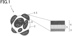
- Fig. 1 is a schematic illustrative view of a cross section of a main part of a preferred embodiment of an ionic-liquid-impregnated catalyst particle according to the present invention.
- ionic-liquid-impregnated catalyst particles contain a catalyst particle 1 having an electrically conductive carrier 2 and metal particles 3 supported by the electrically conductive carrier 2.
- the metal particles 3 are embedded in a porous inorganic material 4.
- a space between the porous inorganic material 4 and the metal particles 3 is impregnated with an ionic liquid 5. That is, the inside of the porous inorganic material 4, including its pores, are filled with the ionic liquid 5.
- the metal particles 3 are mainly embedded in the porous inorganic material 4, and electronic conduction can be ensured.
- the inside of the pores of the porous inorganic material 4 is filled with the ionic liquid 5, and contact between water and the metal particles 3 can be suppressed.
- Filling the inside of the porous inorganic material 4 with the ionic liquid 5 allows for the stable retention of the ionic liquid 5 and suppresses the elution of the metal particles 3. Through the ionic liquid 5, protons can smoothly migrate to the metal particles 3, and resistance overvoltage can be suppressed.
- the filling amount of the ionic liquid 5 (impregnation amount of the ionic liquid 5) has a volume equivalent of 50% by volume or more and 100% by volume or less of the mesopore volume of the catalyst particles 1.
- the mesopore volume can be calculated by, for example, a low-temperature nitrogen adsorption method.
- the used mesopore volume was the total pore volume of pores in the range of 1 nm to 100 nm.
- the filling amount of the ionic liquid 5 is less than 50% by volume, sufficient effects cannot be obtained.
- the ionic liquid 5 flows out during power generation by a fuel cell having an electrode formed with the catalyst particles 1.
- the metal particles 3 used in the catalyst particles 1 contain one or more of Pt, Rh, Pd, Au, and Ir. Examples thereof include Pt alone, alloy particles of Pt and Co, and core-shell particles in which a Pd core is coated with Pt particles.
- the porous inorganic material 4 contains one or more of silica (SiO 2 ), zirconia (ZrO 2 ), and titania (TiO 2 ). As the porous inorganic material 4, silica is preferably used.
- the coating amount of the porous inorganic material 4 is such that the weight ratio (porous inorganic material)/(porous inorganic material + catalyst particles) is in a range of 0.01 or more and 0.2 or less, wherein the weight of the catalyst particles is the total weight of the metal particles and the electrically conductive carrier.
- the coating amount of the porous inorganic material 4 can be calculated by, for example, X-ray photoelectron spectroscopy (XPS).
- XPS X-ray photoelectron spectroscopy
- the ionic liquid 5 contains a 1-alkyl-3-methylimidazolium bis(trifluoromethanesulfonyl)imide, wherein the alkyl portion is any one of methyl, ethyl, propyl, butyl, pentyl, hexyl, and heptyl.
- the alkyl portion is particularly preferably a butyl group.
- a membrane electrode assembly for fuel cells according to the present embodiment includes a catalyst layer formed with the above-described ionic-liquid-impregnated catalyst particles according to the present embodiment.
- Such a membrane electrode assembly for fuel cells is provided with, for example, a polymer electrolyte membrane and a pair of electrode catalyst layers that are formed with the above-described ionic-liquid-impregnated catalyst particles according to the present embodiment and vertically sandwich the polymer electrolyte membrane.
- the ionic-liquid-impregnated catalyst particles on the anode side may be omitted, and the ionic-liquid-impregnated catalyst particles may be used only on the cathode side.
- a fuel cell according to the present embodiment includes the above-described ionic-liquid-impregnated catalyst particles according to the present embodiment.
- Such a fuel cell is provided with, for example, a pair of gas diffusion layers.
- the gas diffusion layers face their corresponding electrode catalyst layers of the above-described membrane electrode assembly according to the present embodiment.
- the gas diffusion layers and their corresponding electrode catalyst layers form a cathode (positive electrode) and an anode (negative electrode).
- the invention according to the present embodiment exerts the following effects.
- the porous inorganic material 4 does not cover the entirety of the catalyst particle 1 and mainly embeds the metal particles 3 therein, and thus, electronic conduction can be ensured by the electrically conductive carrier 2.
- the insides of the pores of the porous inorganic material 4 are filled with the ionic liquid 5, and thus, contact between water and the metal particles 3 can be suppressed, and oxygen reduction properties can be improved.
- the inside of the porous inorganic material 4 is filled with the ionic liquid 5, the ionic liquid 5 can be stably retained by electrostatic interaction even during operation of the fuel cell, and durability can be improved.
- the ionic-liquid-impregnated catalyst particles according to the present embodiment are constituted by the ionic liquid 5, the porous inorganic material 4, and the catalyst particles 1, wherein the content of the ionic liquid 5 is a volume equivalent of 50% by volume or more and 100% by volume or less of the mesopore volume of the catalyst particles 1 containing the porous inorganic material 4.
- the ionic liquid 5 can be stably retained in the porous inorganic material 4, protons can smoothly migrate onto the metal particles 3 through the ionic liquid 5, and resistance overvoltage can be suppressed.
- the metal particles 3 of the catalyst particles 1 used in the ionic-liquid-impregnated catalyst particles according to the present embodiment contain one or more of Pt, Rh, Pd, Au, and Ir. Examples thereof include Pt alone, alloy particles of Pt and Co, and core-shell particles in which a Pd core is coated with Pt particles.
- the porous inorganic material 4 contains one or more of silica (SiO 2 ), zirconia (ZrO 2 ), and titania (TiO 2 ), and silica is preferably used.
- the ionic-liquid-impregnated catalyst particles exhibit high oxygen reduction activity and particularly can be used as a cathode catalyst for fuel cells.
- the weight ratio (porous inorganic material)/(porous inorganic material + catalyst particles) is 0.01 or more and 0.2 or less.
- the catalyst particle 1 is composed of the electrically conductive carrier 2 and the metal particles 3.
- the ionic-liquid-impregnated catalyst particles can retain the ionic liquid 5 by the porous inorganic material 4 while suppressing the influence of the porous inorganic material 4 which is a resistance component.
- the ionic liquid 5 has a chemical structure that contains a 1-alkyl-3-methylimidazolium bis(trifluoromethanesulfonyl)imide in which the alkyl portion is at least one of methyl, ethyl, propyl, butyl, pentyl, hexyl, and heptyl.
- the carbon carrier used had a G band/D band ratio of 1.3 or more by Raman spectroscopy.
- the Pt-supporting carbon was added to and dispersed in a tetradecyltrimethylammonium bromide (TTAB) aqueous solution. Subsequently, a mixed solution of tetraethoxysilane (TEOS) and ethanol was added. Sodium hydroxide was added and the mixture was stirred for 2 hours. Thereafter, the treated Pt-supporting carbon was separated using a centrifugal separator and dried at 80°C for 6 hours. Finally, the adhered TTAB was removed through heat treatment at 350°C under an air atmosphere to obtain silica-coated Pt-supporting carbon. The silica coating amount in the synthesized silica-coated Pt-supporting carbon was adjusted by the amount of TEOS used. The silica coating amount was calculated by XPS.
- the synthesized silica-coated Pt-supporting carbon was added to acetonitrile, and an ionic liquid was added depending on the mesopore volume of the silica-coated Pt-supporting carbon. Ultrasonic dispersion was performed for 30 minutes, and thereafter the acetonitrile was removed using an evaporator to obtain ionic-liquid-impregnated silica-coated Pt-supporting carbon. The added amount of the ionic liquid was calculated based on the mesopore volume in the range of 1 nm to 100 nm by a low-temperature nitrogen adsorption method.
- a mixed solution of water, normal propyl alcohol (NPA), and ethanol (7:2:1), the catalyst particles of each of Examples 1 to 6 and Comparative Examples 1 to 8, and a dispersion liquid of perfluorocarbon ("Nafion (registered trademark)" manufactured by Sigma-Aldrich, Inc. (United States)) were mixed and dispersed using a ball mill to prepare a catalyst ink of each of Examples 1 to 6 and Comparative Examples 1 to 8.
- the I (ionomer)/C (carrier carbon) ratio was 0.8, and the solid content was 14.5% by mass.
- the catalyst ink formed with the catalyst particles according to each of Examples 1 to 6 and Comparative Examples 1 to 8 was applied on a membrane of perfluorocarbon ("Nafion (registered trademark)" manufactured by Sigma-Aldrich, Inc. (United States)) such that the Pt basis weight was 0.44 mg/cm 2 . Subsequently, drying at 80°C for 5 minutes was performed to obtain a cathode-side catalyst layer.
- a gas diffusion layer and a gas seal were laminated to each side of the obtained membrane electrode assembly.
- the product was set in a standard Japan Automobile Research Institute (JARI) cell (electrode area 5 ⁇ 5 cm 2 ), and I-V measurement was performed in accordance with the cell evaluation analysis protocol of the New Energy and Industrial Technology Development Organization (NEDO).
- JARI Japan Automobile Research Institute
- NEDO New Energy and Industrial Technology Development Organization
- the current density was shifted from low current density to high current density while maintaining the measurement current density for 5 minutes.
- the measurement current densities were 0, 0.025, 0.050, 0.075, 0.1, 0.2, 0.4, 0.6, 0.8, 1.0, 1.2, 1.4, 1.5, and 1.6 A/cm 2 .
- the durability test was also performed in accordance with the NEDO cell evaluation analysis protocol. In a potential cycle test of load response simulation, 30,000 cycles were performed.
- Table 1 shows the evaluation results for the fuel cells including the catalysts of Examples 1 to 6 and Comparative Examples 1 to 8 when I-V measurement was performed before and after the durability test. Specifically, with Comparative Example 1 (Pt-supporting carbon) as a reference, “Poor” is assigned when the voltage difference at 1.5 A/cm 2 during I-V measurement is less than 0 mV, “Good” when 0 to 10 mV, and “Excellent” when more than 10 mV.
- Comparative Example 6 using Pt-supporting carbon coated with only silica, the voltage after the durability test was higher than that in Comparative Example 1, and durability was high.
- Comparative Example 7 using a catalyst filled with only an ionic liquid, the voltage was higher than that in Comparative Example 1 both before and after the durability test, but the difference was small.
- Examples 1, 2, and 3 and Comparative Examples 2 and 3 are evaluations of ionic-liquid-impregnated silica-coated Pt-supporting carbon adjusted to have different silica coating amounts, and the voltage after the durability test was higher than that in Comparative Example 1 when the silica coating amount was 1% by mass or more and 20% by mass or less.
- Examples 1, 4, and 5 and Comparative Examples 4 and 5 are evaluations of ionic-liquid-impregnated silica-coated Pt-supporting carbon adjusted to have different ionic-liquid filling amounts, and the voltage before the durability test was higher than that in Comparative Example 1 when the ionic-liquid filling amount was 50% by mass or more and 100% by mass or less.
- Example 6 the ionic liquid was changed from 1-butyl-3-methylimidazolium bis(trifluoromethanesulfonyl)imide to 1-ethyl-3-methylimidazolium bis(trifluoromethanesulfonyl)imide.
- Comparative Example 8 the ionic liquid was changed from 1-butyl-3-methylimidazolium bis(trifluoromethanesulfonyl)imide to 1-octyl-3-methylimidazolium bis(trifluoromethanesulfonyl)imide.
- the ionic liquid has the effect of suppressing adsorbed species that inhibit oxygen reduction of the Pt surface but cannot sufficiently coat low-coordinated Pt sites.
- a silica coating can selectively coat and protect low-coordinated Pt sites but is hydrophilic and thus has less effect of suppressing water-derived adsorbed species that inhibit oxygen reduction than the ionic liquid does. Therefore, it is considered that combining a silica coating and the ionic liquid provided high oxygen reduction properties while also improving the electrochemical stability of Pt.
- the ionic-liquid-impregnated catalyst particles, the membrane electrode assembly for fuel cells, and the fuel cell according to the present invention have good oxygen reduction properties and are excellent in durability and thus can be significantly effectively utilized industrially.
Landscapes
- Chemical & Material Sciences (AREA)
- Chemical Kinetics & Catalysis (AREA)
- Engineering & Computer Science (AREA)
- Materials Engineering (AREA)
- Organic Chemistry (AREA)
- General Chemical & Material Sciences (AREA)
- Electrochemistry (AREA)
- Life Sciences & Earth Sciences (AREA)
- Manufacturing & Machinery (AREA)
- Sustainable Development (AREA)
- Sustainable Energy (AREA)
- Catalysts (AREA)
- Inert Electrodes (AREA)
- Fuel Cell (AREA)
Abstract
Description
- The present invention relates to ionic-liquid-impregnated catalyst particles, a membrane electrode assembly formed with the ionic-liquid-impregnated catalyst particles, and a fuel cell provided with the membrane electrode assembly.
- There are known polymer electrolyte fuel cells that have a fuel cell provided with an electrolyte layer formed from ion exchange resin, a fuel-side electrode (anode) to which fuel is supplied, and an oxygen-side electrode (cathode) to which oxygen is supplied. In such a fuel cell, fuel is supplied to an anode while air is supplied to a cathode, which causes occurrence of an electromotive force and generates power. For example, a platinum-supporting carbon catalyst in which carbon supports platinum is proposed as the cathode catalyst. However, the platinum-supporting carbon catalyst has a problem in durability, and the supported platinum particles elute into the electrolyte layer, leading to a decrease in performance of the fuel cell.
- Therefore, for example, PTL 1 described below proposes an electrode material in which an electrically conductive carrier and metal particles arranged on the electrically conductive carrier are embedded in a porous inorganic material to prevent the elution of the metal particles and suppress a decrease in performance of a fuel cell. Further, NPL 1 described below reports that oxygen reduction activity can be improved by applying an ionic liquid around Pt catalyst particles for suppressing a reaction between Pt catalyst particles and water.
- PTL 1:
JP 2008-4541 A - NPL 1: ACS Catalysis, 2018, 8, 8244-8254
- However, the electrode material described in PTL 1 has the effect of suppressing the elution of metal particles but had a problem in that since the porous inorganic material covers the metal particles, a contact with an ionomer deteriorates, which increases resistance and causes a reduction in voltage. In the technology described in NPL 1, an ionic liquid is mainly held in pores of a carrier of Pt catalyst particles. Therefore, when the carrier is highly crystalline carbon, an ionic liquid is unlikely to be sufficiently held because of the low porosity of the carrier, and the coating effect produced by the ionic liquid was not sufficiently obtained. Further, in the case of highly loaded Pt catalyst particles that are mainly loaded on the surface of the carrier, the coating effect produced by the ionic liquid was not sufficiently obtained either.
- The present invention focuses on the above-described points and has as its object to provide ionic-liquid-impregnated catalyst particles, a membrane electrode assembly for fuel cells, and a fuel cell, which are excellent in oxygen reduction activity and suppress the elution of metal particles from the catalyst particles.
- The present inventor intensively conducted studies and found that, in a highly crystalline carbon carrier and catalyst particles in which metal particles are highly supported, embedding the metal particles in a porous inorganic material and impregnating the catalyst particles with an ionic liquid can improve oxygen reduction activity and suppress elution of metal particles, compared with catalyst particles containing a porous inorganic material and catalyst particles coated with an ionic liquid. Thus, the present invention has been accomplished.
- Ionic-liquid-impregnated catalyst particles according to the present invention for solving the previously described problem are catalyst particles including an electrically conductive carrier and metal particles supported by the electrically conductive carrier, wherein the metal particles are embedded in a porous inorganic material, and the catalyst particles containing the porous inorganic material are impregnated with an ionic liquid.
- The porous inorganic material preferably has a weight ratio (porous inorganic material)/(porous inorganic material + catalyst particles) of 0.01 or more and 0.2 or less.
- An impregnation amount of the ionic liquid is preferably 50% by volume or more and 100% by volume or less of a mesopore volume of the catalyst particles containing the porous inorganic material.
- The ionic liquid preferably contains a 1-alkyl-3-methylimidazolium bis(trifluoromethanesulfonyl)imide (where, alkyl is any one of methyl, ethyl, propyl, butyl, pentyl, hexyl, and heptyl).
- A membrane electrode assembly for fuel cells according to the present invention for solving the previously described problem includes a catalyst layer formed with the above-described ionic-liquid-impregnated catalyst particles according to the present invention.
- A fuel cell according to the present invention for solving the previously described problem includes the above-described ionic-liquid-impregnated catalyst particles according to the present invention. For example, the fuel cell may be provided with the above-described membrane electrode assembly provided with a catalyst layer formed with the ionic-liquid-impregnated catalyst particles according to the present invention.
- According to the present invention, the porous inorganic material allows for suppression of the elution of the metal particles and stable retention of the ionic liquid on the surface of the metal particles. Therefore, there can be provided ionic-liquid-impregnated catalyst particles, a membrane electrode assembly for fuel cells, and a fuel cell having good oxygen reduction properties and excellent in durability.
-
Fig. 1 is a schematic illustrative view of a cross section of a main part of a preferred embodiment of an ionic-liquid-impregnated catalyst particle according to the present invention. - Embodiments of ionic-liquid-impregnated catalyst particles, a membrane electrode assembly for fuel cells, and a fuel cell according to the present invention will be described below with reference to the drawing. It should be noted that the present invention is not limited to only embodiments described below with reference to the drawing, and technical matters described in the embodiments can be appropriately combined as necessary.
- A preferred embodiment of ionic-liquid-impregnated catalyst particles, a membrane electrode assembly for fuel cells, and a fuel cell according to the present invention will be described below with reference to
Fig. 1 . - As illustrated in
Fig. 1 , ionic-liquid-impregnated catalyst particles according to the present embodiment contain a catalyst particle 1 having an electrically conductive carrier 2 andmetal particles 3 supported by the electrically conductive carrier 2. Themetal particles 3 are embedded in a porous inorganic material 4. A space between the porous inorganic material 4 and themetal particles 3 is impregnated with anionic liquid 5. That is, the inside of the porous inorganic material 4, including its pores, are filled with theionic liquid 5. - The
metal particles 3 are mainly embedded in the porous inorganic material 4, and electronic conduction can be ensured. The inside of the pores of the porous inorganic material 4 is filled with theionic liquid 5, and contact between water and themetal particles 3 can be suppressed. Filling the inside of the porous inorganic material 4 with theionic liquid 5 allows for the stable retention of theionic liquid 5 and suppresses the elution of themetal particles 3. Through theionic liquid 5, protons can smoothly migrate to themetal particles 3, and resistance overvoltage can be suppressed. - The filling amount of the ionic liquid 5 (impregnation amount of the ionic liquid 5) has a volume equivalent of 50% by volume or more and 100% by volume or less of the mesopore volume of the catalyst particles 1. The mesopore volume can be calculated by, for example, a low-temperature nitrogen adsorption method. The used mesopore volume was the total pore volume of pores in the range of 1 nm to 100 nm. When the filling amount of the
ionic liquid 5 is less than 50% by volume, sufficient effects cannot be obtained. When more than 100% by volume, theionic liquid 5 flows out during power generation by a fuel cell having an electrode formed with the catalyst particles 1. - The
metal particles 3 used in the catalyst particles 1 contain one or more of Pt, Rh, Pd, Au, and Ir. Examples thereof include Pt alone, alloy particles of Pt and Co, and core-shell particles in which a Pd core is coated with Pt particles. The porous inorganic material 4 contains one or more of silica (SiO2), zirconia (ZrO2), and titania (TiO2). As the porous inorganic material 4, silica is preferably used. - The coating amount of the porous inorganic material 4 is such that the weight ratio (porous inorganic material)/(porous inorganic material + catalyst particles) is in a range of 0.01 or more and 0.2 or less, wherein the weight of the catalyst particles is the total weight of the metal particles and the electrically conductive carrier.
- The coating amount of the porous inorganic material 4 can be calculated by, for example, X-ray photoelectron spectroscopy (XPS). When the coating amount of the porous inorganic material 4 is less than 1% by mass, it is difficult to sufficiently retain the
ionic liquid 5 inside the porous inorganic material 4, and when more than 20% by mass, it is difficult to sufficiently ensure the electrical conductivity of the catalyst particles 1. - The
ionic liquid 5 contains a 1-alkyl-3-methylimidazolium bis(trifluoromethanesulfonyl)imide, wherein the alkyl portion is any one of methyl, ethyl, propyl, butyl, pentyl, hexyl, and heptyl. The alkyl portion is particularly preferably a butyl group. - A membrane electrode assembly for fuel cells according to the present embodiment includes a catalyst layer formed with the above-described ionic-liquid-impregnated catalyst particles according to the present embodiment. Such a membrane electrode assembly for fuel cells is provided with, for example, a polymer electrolyte membrane and a pair of electrode catalyst layers that are formed with the above-described ionic-liquid-impregnated catalyst particles according to the present embodiment and vertically sandwich the polymer electrolyte membrane. It should be noted that in the membrane electrode assembly for fuel cells, the ionic-liquid-impregnated catalyst particles on the anode side may be omitted, and the ionic-liquid-impregnated catalyst particles may be used only on the cathode side.
- A fuel cell according to the present embodiment includes the above-described ionic-liquid-impregnated catalyst particles according to the present embodiment. Such a fuel cell is provided with, for example, a pair of gas diffusion layers. The gas diffusion layers face their corresponding electrode catalyst layers of the above-described membrane electrode assembly according to the present embodiment. The gas diffusion layers and their corresponding electrode catalyst layers form a cathode (positive electrode) and an anode (negative electrode).
- The invention according to the present embodiment exerts the following effects.
-
- (1) In the ionic-liquid-impregnated catalyst particles according to the present embodiment, the catalyst particles 1 include the electrically conductive carrier 2 and the
metal particles 3 supported by the electrically conductive carrier 2, wherein at least themetal particles 3 are embedded in the porous inorganic material 4, and the inside of the porous inorganic material 4 is filled with anionic liquid 5. - With this configuration, the porous inorganic material 4 does not cover the entirety of the catalyst particle 1 and mainly embeds the
metal particles 3 therein, and thus, electronic conduction can be ensured by the electrically conductive carrier 2. The insides of the pores of the porous inorganic material 4 are filled with theionic liquid 5, and thus, contact between water and themetal particles 3 can be suppressed, and oxygen reduction properties can be improved. When the inside of the porous inorganic material 4 is filled with theionic liquid 5, theionic liquid 5 can be stably retained by electrostatic interaction even during operation of the fuel cell, and durability can be improved. - (2) The ionic-liquid-impregnated catalyst particles according to the present embodiment are constituted by the
ionic liquid 5, the porous inorganic material 4, and the catalyst particles 1, wherein the content of theionic liquid 5 is a volume equivalent of 50% by volume or more and 100% by volume or less of the mesopore volume of the catalyst particles 1 containing the porous inorganic material 4. - With this configuration, the
ionic liquid 5 can be stably retained in the porous inorganic material 4, protons can smoothly migrate onto themetal particles 3 through theionic liquid 5, and resistance overvoltage can be suppressed. - (3) The
metal particles 3 of the catalyst particles 1 used in the ionic-liquid-impregnated catalyst particles according to the present embodiment contain one or more of Pt, Rh, Pd, Au, and Ir. Examples thereof include Pt alone, alloy particles of Pt and Co, and core-shell particles in which a Pd core is coated with Pt particles. The porous inorganic material 4 contains one or more of silica (SiO2), zirconia (ZrO2), and titania (TiO2), and silica is preferably used. - With this configuration, the ionic-liquid-impregnated catalyst particles exhibit high oxygen reduction activity and particularly can be used as a cathode catalyst for fuel cells.
- (4) In the porous inorganic material 4 of the ionic-liquid-impregnated catalyst particles according to the present embodiment, the weight ratio (porous inorganic material)/(porous inorganic material + catalyst particles) is 0.01 or more and 0.2 or less. The catalyst particle 1 is composed of the electrically conductive carrier 2 and the
metal particles 3. - With this configuration, the ionic-liquid-impregnated catalyst particles can retain the
ionic liquid 5 by the porous inorganic material 4 while suppressing the influence of the porous inorganic material 4 which is a resistance component. - (5) In the ionic-liquid-impregnated catalyst particles according to the present embodiment, the
ionic liquid 5 has a chemical structure that contains a 1-alkyl-3-methylimidazolium bis(trifluoromethanesulfonyl)imide in which the alkyl portion is at least one of methyl, ethyl, propyl, butyl, pentyl, hexyl, and heptyl. - With such an
ionic liquid 5, protons and oxygen can smoothly migrate to themetal particles 3 even when themetal particles 3 of the catalyst particles 1 are coated, and good oxygen reduction activity can be exhibited. - Examples of the ionic-liquid-impregnated catalyst particles, the membrane electrode assembly for fuel cells, and the fuel cell according to the present invention will be specifically described. It should be noted that the present invention is not limited to only examples specifically described below, and technical matters of the examples can be appropriately combined as necessary.
- Pt-supporting carbon is synthesized according to a known method, and the amount of Pt supported was given by the ratio Pt/C = 70/30 (mass ratio). The carbon carrier used had a G band/D band ratio of 1.3 or more by Raman spectroscopy.
- The Pt-supporting carbon was added to and dispersed in a tetradecyltrimethylammonium bromide (TTAB) aqueous solution. Subsequently, a mixed solution of tetraethoxysilane (TEOS) and ethanol was added. Sodium hydroxide was added and the mixture was stirred for 2 hours. Thereafter, the treated Pt-supporting carbon was separated using a centrifugal separator and dried at 80°C for 6 hours. Finally, the adhered TTAB was removed through heat treatment at 350°C under an air atmosphere to obtain silica-coated Pt-supporting carbon. The silica coating amount in the synthesized silica-coated Pt-supporting carbon was adjusted by the amount of TEOS used. The silica coating amount was calculated by XPS.
- The synthesized silica-coated Pt-supporting carbon was added to acetonitrile, and an ionic liquid was added depending on the mesopore volume of the silica-coated Pt-supporting carbon. Ultrasonic dispersion was performed for 30 minutes, and thereafter the acetonitrile was removed using an evaporator to obtain ionic-liquid-impregnated silica-coated Pt-supporting carbon. The added amount of the ionic liquid was calculated based on the mesopore volume in the range of 1 nm to 100 nm by a low-temperature nitrogen adsorption method.
- According to the previously described process, silica-coated Pt-supporting carbon having a silica coating amount of 10% by mass was synthesized with Pt-supporting carbon (Pt/C = 70/30 (mass ratio)), and 1-butyl-3-methylimidazolium bis(trifluoromethanesulfonyl)imide having a volume that is 80% by volume of the mesopore volume was used to obtain catalyst particles (ionic-liquid-impregnated silica-coated Pt-supporting carbon) of Example 1.
- According to the previously described process, silica-coated Pt-supporting carbon having a silica coating amount of 1% by mass was synthesized with Pt-supporting carbon (Pt/C = 70/30 (mass ratio)), and 1-butyl-3-methylimidazolium bis(trifluoromethanesulfonyl)imide having a volume that is 80% by volume of the mesopore volume was used to obtain catalyst particles (ionic-liquid-impregnated silica-coated Pt-supporting carbon) of Example 2.
- According to the previously described process, silica-coated Pt-supporting carbon having a silica coating amount of 20% by mass was synthesized with Pt-supporting carbon (Pt/C = 70/30 (mass ratio)), and 1-butyl-3-methylimidazolium bis(trifluoromethanesulfonyl)imide having a volume that is 80% by volume of the mesopore volume was used to obtain catalyst particles (ionic-liquid-impregnated silica-coated Pt-supporting carbon) of Example 3.
- According to the previously described process, silica-coated Pt-supporting carbon having a silica coating amount of 10% by mass was synthesized with Pt-supporting carbon (Pt/C = 70/30 (mass ratio)), and 1-butyl-3-methylimidazolium bis(trifluoromethanesulfonyl)imide having a volume that is 50% by volume of the mesopore volume was used to obtain catalyst particles (ionic-liquid-impregnated silica-coated Pt-supporting carbon) of Example 4.
- According to the previously described process, silica-coated Pt-supporting carbon having a silica coating amount of 10% by mass was synthesized with Pt-supporting carbon (Pt/C = 70/30 (mass ratio)), and 1-butyl-3-methylimidazolium bis(trifluoromethanesulfonyl)imide having a volume that is 100% by volume of the mesopore volume was used to obtain catalyst particles (ionic-liquid-impregnated silica-coated Pt-supporting carbon) of Example 5.
- According to the previously described process, silica-coated Pt-supporting carbon having a silica coating amount of 10% by mass was synthesized with Pt-supporting carbon (Pt/C = 70/30 (mass ratio)), and 1-ethyl-3-methylimidazolium bis(trifluoromethanesulfonyl)imide having a volume that is 80% by volume of the mesopore volume was used to obtain catalyst particles (ionic-liquid-impregnated silica-coated Pt-supporting carbon) of Example 6.
- Pt-supporting carbon (Pt/C = 70/30 (mass ratio)) was used as catalyst particles (Pt-supporting carbon) of Comparative Example 1.
- According to the previously described process, silica-coated Pt-supporting carbon having a silica coating amount of 0.1% by mass was synthesized with Pt-supporting carbon (Pt/C = 70/30 (mass ratio)), and 1-butyl-3-methylimidazolium bis(trifluoromethanesulfonyl)imide having a volume that is 80% by volume of the mesopore volume was used to obtain catalyst particles (ionic-liquid-impregnated silica-coated Pt-supporting carbon) of Comparative Example 2.
- According to the previously described process, silica-coated Pt-supporting carbon having a silica coating amount of 30% by mass was synthesized with Pt-supporting carbon (Pt/C = 70/30 (mass ratio)), and 1-butyl-3-methylimidazolium bis(trifluoromethanesulfonyl)imide having a volume that is 50% by volume of the mesopore volume was used to obtain catalyst particles (ionic-liquid-impregnated silica-coated Pt-supporting carbon) of Comparative Example 3.
- According to the previously described process, silica-coated Pt-supporting carbon having a silica coating amount of 10% by mass was synthesized with Pt-supporting carbon (Pt/C = 70/30 (mass ratio)), and 1-butyl-3-methylimidazolium bis(trifluoromethanesulfonyl)imide having a volume that is 40% by volume of the mesopore volume was used to obtain catalyst particles (ionic-liquid-impregnated silica-coated Pt-supporting carbon) of Comparative Example 4.
- According to the previously described process, silica-coated Pt-supporting carbon having a silica coating amount of 10% by mass was synthesized with Pt-supporting carbon (Pt/C = 70/30 (mass ratio)), and 1-butyl-3-methylimidazolium bis(trifluoromethanesulfonyl)imide having a volume that is 110% by volume of the mesopore volume was used to obtain catalyst particles (ionic-liquid-impregnated silica-coated Pt-supporting carbon) of Comparative Example 5.
- According to the previously described process, silica-coated Pt-supporting carbon having a silica coating amount of 10% by mass was synthesized with Pt-supporting carbon (Pt/C = 70/30 (mass ratio)) to obtain catalyst particles (silica-coated Pt-supporting carbon) of Comparative Example 6.
- According to the previously described process, 1-butyl-3-methylimidazolium bis(trifluoromethanesulfonyl)imide having a volume that is 80% by volume of the mesopore volume was used with Pt-supporting carbon (Pt/C = 70/30 (mass ratio)) to obtain catalyst particles (ionic-liquid-impregnated Pt-supporting carbon) of Comparative Example 7.
- According to the previously described process, silica-coated Pt-supporting carbon having a silica coating amount of 10% by mass was synthesized with Pt-supporting carbon (Pt/C = 70/30 (mass ratio)), and 1-octyl-3-methylimidazolium bis(trifluoromethanesulfonyl)imide having a volume that is 80% by mass of the mesopore volume was used to obtain catalyst particles (ionic-liquid-impregnated silica-coated Pt-supporting carbon) of Comparative Example 8.
- A mixed solution of water, normal propyl alcohol (NPA), and ethanol (7:2:1), the catalyst particles of each of Examples 1 to 6 and Comparative Examples 1 to 8, and a dispersion liquid of perfluorocarbon ("Nafion (registered trademark)" manufactured by Sigma-Aldrich, Inc. (United States)) were mixed and dispersed using a ball mill to prepare a catalyst ink of each of Examples 1 to 6 and Comparative Examples 1 to 8. The I (ionomer)/C (carrier carbon) ratio was 0.8, and the solid content was 14.5% by mass.
- The catalyst ink formed with the catalyst particles according to each of Examples 1 to 6 and Comparative Examples 1 to 8 was applied on a membrane of perfluorocarbon ("Nafion (registered trademark)" manufactured by Sigma-Aldrich, Inc. (United States)) such that the Pt basis weight was 0.44 mg/cm2. Subsequently, drying at 80°C for 5 minutes was performed to obtain a cathode-side catalyst layer. Pt-supporting carbon (Pt/C = 30/70 (mass ratio)) was used to prepare a catalyst ink in the same manner as described above, and this catalyst ink was applied on the perfluorocarbon membrane opposite the cathode-side catalyst layer such that the Pt basis weight was 0.1 mg/cm2. Subsequently, drying at 80°C for 5 minutes was performed to obtain an anode-side catalyst layer. Thus, a membrane electrode assembly of each of Examples 1 to 6 and Comparative Examples 1 to 8 was prepared.
- A gas diffusion layer and a gas seal were laminated to each side of the obtained membrane electrode assembly. The product was set in a standard Japan Automobile Research Institute (JARI) cell (
electrode area 5 × 5 cm2), and I-V measurement was performed in accordance with the cell evaluation analysis protocol of the New Energy and Industrial Technology Development Organization (NEDO). The current density was shifted from low current density to high current density while maintaining the measurement current density for 5 minutes. The measurement current densities were 0, 0.025, 0.050, 0.075, 0.1, 0.2, 0.4, 0.6, 0.8, 1.0, 1.2, 1.4, 1.5, and 1.6 A/cm2. - The durability test was also performed in accordance with the NEDO cell evaluation analysis protocol. In a potential cycle test of load response simulation, 30,000 cycles were performed.
- Table 1 shows the evaluation results for the fuel cells including the catalysts of Examples 1 to 6 and Comparative Examples 1 to 8 when I-V measurement was performed before and after the durability test. Specifically, with Comparative Example 1 (Pt-supporting carbon) as a reference, "Poor" is assigned when the voltage difference at 1.5 A/cm2 during I-V measurement is less than 0 mV, "Good" when 0 to 10 mV, and "Excellent" when more than 10 mV.
[Table 1] Silica coating amount (wt%) Impregnation amount of ionic liquid (vol%) Voltage before durability test (V@1.5 A/cm2) Voltage after durability test (V@1.5 A/cm2) Example 1 10 80 Excellent Excellent Example 2 1 80 Good Excellent Example 3 20 80 Good Excellent Example 4 10 50 Excellent Excellent Example 5 10 100 Excellent Good Example 6 10 80 Excellent Excellent Comparative Example 1 0 0 - - Comparative Example 2 0.1 80 Poor Good Comparative Example 3 30 80 Poor Excellent Comparative Example 4 10 40 Poor Good Comparative Example 5 10 110 Poor Good Comparative Example 6 10 0 Poor Excellent Comparative Example 7 0 80 Good Good Comparative Example 8 10 80 Poor Poor - As shown in Table 1, in Comparative Example 6 using Pt-supporting carbon coated with only silica, the voltage after the durability test was higher than that in Comparative Example 1, and durability was high. In Comparative Example 7 using a catalyst filled with only an ionic liquid, the voltage was higher than that in Comparative Example 1 both before and after the durability test, but the difference was small.
- Examples 1, 2, and 3 and Comparative Examples 2 and 3 are evaluations of ionic-liquid-impregnated silica-coated Pt-supporting carbon adjusted to have different silica coating amounts, and the voltage after the durability test was higher than that in Comparative Example 1 when the silica coating amount was 1% by mass or more and 20% by mass or less.
- Examples 1, 4, and 5 and Comparative Examples 4 and 5 are evaluations of ionic-liquid-impregnated silica-coated Pt-supporting carbon adjusted to have different ionic-liquid filling amounts, and the voltage before the durability test was higher than that in Comparative Example 1 when the ionic-liquid filling amount was 50% by mass or more and 100% by mass or less.
- In Example 6, the ionic liquid was changed from 1-butyl-3-methylimidazolium bis(trifluoromethanesulfonyl)imide to 1-ethyl-3-methylimidazolium bis(trifluoromethanesulfonyl)imide. In Comparative Example 8, the ionic liquid was changed from 1-butyl-3-methylimidazolium bis(trifluoromethanesulfonyl)imide to 1-octyl-3-methylimidazolium bis(trifluoromethanesulfonyl)imide. With a shorter carbon chain in the alkyl portion of 1-alkyl-3-methylimidazolium bis(trifluoromethanesulfonyl)imide, the voltages both before and after the durability test were higher than those in Comparative Example 1. On the other hand, with a longer carbon chain, the voltages both before and after the durability test were lower than those in Comparative Example 1.
- These demonstrated that the voltages before and after the durability test can be significantly increased by filling the pores of silica with the ionic liquid. It is considered that this is due to the following reason. The ionic liquid has the effect of suppressing adsorbed species that inhibit oxygen reduction of the Pt surface but cannot sufficiently coat low-coordinated Pt sites. On the other hand, a silica coating can selectively coat and protect low-coordinated Pt sites but is hydrophilic and thus has less effect of suppressing water-derived adsorbed species that inhibit oxygen reduction than the ionic liquid does. Therefore, it is considered that combining a silica coating and the ionic liquid provided high oxygen reduction properties while also improving the electrochemical stability of Pt.
- The ionic-liquid-impregnated catalyst particles, the membrane electrode assembly for fuel cells, and the fuel cell according to the present invention have good oxygen reduction properties and are excellent in durability and thus can be significantly effectively utilized industrially.
-
- 1
- Catalyst particle
- 2
- Electrically conductive carrier
- 3
- Metal particles
- 4
- Porous inorganic material
- 5
- Ionic liquid
Claims (6)
- Ionic-liquid-impregnated catalyst particles comprising:an electrically conductive carrier; andmetal particles supported by the electrically conductive carrier, whereinthe metal particles are embedded in a porous inorganic material, andthe catalyst particles containing the porous inorganic material are impregnated with an ionic liquid.
- The ionic-liquid-impregnated catalyst particles according to claim 1, wherein
the porous inorganic material has a weight ratio (porous inorganic material)/(porous inorganic material + catalyst particles) of 0.01 or more and 0.2 or less. - The ionic-liquid-impregnated catalyst particles according to claim 1, wherein
an impregnation amount of the ionic liquid is 50% by volume or more and 100% by volume or less of a mesopore volume of the catalyst particles containing the porous inorganic material. - The ionic-liquid-impregnated catalyst particles according to claim 1, wherein
the ionic liquid contains a 1-alkyl-3-methylimidazolium bis(trifluoromethanesulfonyl)imide (where, alkyl is any one of methyl, ethyl, propyl, butyl, pentyl, hexyl, and heptyl). - A membrane electrode assembly for fuel cells, the membrane electrode assembly comprising a catalyst layer formed with the ionic-liquid-impregnated catalyst particles according to any one of claims 1 to 4.
- A fuel cell comprising the ionic-liquid-impregnated catalyst particles according to any one of claims 1 to 4.
Applications Claiming Priority (2)
| Application Number | Priority Date | Filing Date | Title |
|---|---|---|---|
| JP2021110203 | 2021-07-01 | ||
| PCT/JP2022/026308 WO2023277148A1 (en) | 2021-07-01 | 2022-06-30 | Ionic liquid-impregnated catalyst particles, membrane electrode assembly for fuel cells, and fuel cell |
Publications (2)
| Publication Number | Publication Date |
|---|---|
| EP4364847A1 true EP4364847A1 (en) | 2024-05-08 |
| EP4364847A4 EP4364847A4 (en) | 2025-08-06 |
Family
ID=84692748
Family Applications (1)
| Application Number | Title | Priority Date | Filing Date |
|---|---|---|---|
| EP22833294.6A Pending EP4364847A4 (en) | 2021-07-01 | 2022-06-30 | Ionic liquid-impregnated catalyst particles, membrane electrode assembly for fuel cells, and fuel cell |
Country Status (5)
| Country | Link |
|---|---|
| US (1) | US20240128473A1 (en) |
| EP (1) | EP4364847A4 (en) |
| JP (1) | JP7396539B2 (en) |
| CN (1) | CN117500593A (en) |
| WO (1) | WO2023277148A1 (en) |
Cited By (1)
| Publication number | Priority date | Publication date | Assignee | Title |
|---|---|---|---|---|
| EP4451393A4 (en) * | 2021-12-15 | 2025-07-30 | Toppan Holdings Inc | IONIC LIQUID IMPREGNATED CATALYST PARTICLES WITH INORGANIC COATED MATERIAL, MEMBRANE-ELECTRODE ASSEMBLY FOR FUEL CELL AND FUEL CELL |
Family Cites Families (5)
| Publication number | Priority date | Publication date | Assignee | Title |
|---|---|---|---|---|
| JP2008177134A (en) | 2007-01-22 | 2008-07-31 | Shinshu Univ | Catalyst electrode for fuel cell and production method thereof |
| JP2008282635A (en) | 2007-05-09 | 2008-11-20 | Nissan Motor Co Ltd | Electrocatalyst, fuel cell using the same, and production method thereof |
| JP6675705B2 (en) | 2014-02-07 | 2020-04-01 | 日産自動車株式会社 | Anode electrode catalyst, electrode catalyst layer using the catalyst, membrane electrode assembly, and fuel cell |
| US11121379B2 (en) * | 2015-01-15 | 2021-09-14 | GM Global Technology Operations LLC | Caged nanoparticle electrocatalyst with high stability and gas transport property |
| WO2019208310A1 (en) | 2018-04-25 | 2019-10-31 | ステラケミファ株式会社 | Fuel cell catalyst, membrane electrode assembly for fuel cell, and fuel cell provided therewith |
-
2022
- 2022-06-30 CN CN202280043640.3A patent/CN117500593A/en active Pending
- 2022-06-30 WO PCT/JP2022/026308 patent/WO2023277148A1/en not_active Ceased
- 2022-06-30 EP EP22833294.6A patent/EP4364847A4/en active Pending
- 2022-06-30 JP JP2023532065A patent/JP7396539B2/en active Active
-
2023
- 2023-12-27 US US18/397,884 patent/US20240128473A1/en active Pending
Cited By (1)
| Publication number | Priority date | Publication date | Assignee | Title |
|---|---|---|---|---|
| EP4451393A4 (en) * | 2021-12-15 | 2025-07-30 | Toppan Holdings Inc | IONIC LIQUID IMPREGNATED CATALYST PARTICLES WITH INORGANIC COATED MATERIAL, MEMBRANE-ELECTRODE ASSEMBLY FOR FUEL CELL AND FUEL CELL |
Also Published As
| Publication number | Publication date |
|---|---|
| CN117500593A (en) | 2024-02-02 |
| WO2023277148A1 (en) | 2023-01-05 |
| JP7396539B2 (en) | 2023-12-12 |
| JPWO2023277148A1 (en) | 2023-01-05 |
| EP4364847A4 (en) | 2025-08-06 |
| US20240128473A1 (en) | 2024-04-18 |
Similar Documents
| Publication | Publication Date | Title |
|---|---|---|
| US6074773A (en) | Impregnation of microporous electrocatalyst particles for improving performance in an electrochemical fuel cell | |
| EP1427048B1 (en) | Membrane electrode assembly for polymer electrolyte fuel cell | |
| US10950869B2 (en) | Fuel cell electrode catalyst and method for producing the same | |
| US5922488A (en) | Co-tolerant fuel cell electrode | |
| EP3641035A1 (en) | Electrode catalyst of electrochemical device, electrode catalyst layer of electrochemical device, membrane electrode assembly of electrochemical device, electrochemical device, method for manufacturing electrode catalyst of electrochemical device, and method for manufacturing membrane electrode assembly of electrochemical device | |
| KR100575099B1 (en) | Catalyst for anode of polymer solid electrolyte fuel cell | |
| EP4451393A1 (en) | Ionic liquid-impregnated inorganic material-coated catalyst particles, membrane electrode assembly for fuel cells, and fuel cell | |
| US20140199609A1 (en) | Electrocatalyst for Solid Polymer Fuel Cell | |
| KR102288596B1 (en) | Catalyst electrode for fuel cell, manufacturing method thereof and a fuel cell comprising the catalyst electrode for fuel cell | |
| EP3855543A1 (en) | Anode catalyst layer for fuel cell and fuel cell using same | |
| EP3855542A1 (en) | Anode catalyst layer for fuel cell and fuel cell using same | |
| JP7399582B2 (en) | Cathode catalyst layer, membrane electrode assembly and fuel cell | |
| US20100068591A1 (en) | Fuel cell catalyst, fuel cell cathode and polymer electrolyte fuel cell including the same | |
| US20240128473A1 (en) | Ionic-liquid-impregnated catalyst particles, membrane electrode assembly for fuel cells, and fuel cell | |
| EP4074418B1 (en) | Electrode catalyst for fuel cell, electrode catalyst layer for fuel cell, membrane/electrode assembly, and fuel cell | |
| EP2690692A2 (en) | Fuel cell anode catalyst and manufacturing method therefor | |
| EP2003717A2 (en) | Electrode catalyst for electrochemical cell, method for manufacturing the same, electrochemical cell, unit cell for fuel battery, and fuel battery | |
| EP4299177A1 (en) | Electrode catalyst, manufacturing method therefor, and fuel cell | |
| EP3855544A1 (en) | Anode catalyst layer for fuel cell and fuel cell using same | |
| KR102299218B1 (en) | Ionomer-ionomer support composite, method for preparing the same, and catalyst electrode for fuel cell comprising the ionomer-ionomer support composite | |
| JP2017188335A (en) | Manufacturing method of membrane electrode assembly | |
| Miyamoto et al. | Pt-Ta-Co electrocatalysts for polymer electrolyte fuel cells | |
| JP2024057940A (en) | Ionic liquid-impregnated silica-coated catalyst particles, membrane electrode assembly, and fuel cell | |
| EP4035769B1 (en) | Catalyst, catalyst layer, membrane electrode assembly, electrochemical device, and method for producing catalyst | |
| EP4697416A1 (en) | Catalyst particles, membrane electrode assembly, and fuel cell |
Legal Events
| Date | Code | Title | Description |
|---|---|---|---|
| STAA | Information on the status of an ep patent application or granted ep patent |
Free format text: STATUS: THE INTERNATIONAL PUBLICATION HAS BEEN MADE |
|
| PUAI | Public reference made under article 153(3) epc to a published international application that has entered the european phase |
Free format text: ORIGINAL CODE: 0009012 |
|
| STAA | Information on the status of an ep patent application or granted ep patent |
Free format text: STATUS: REQUEST FOR EXAMINATION WAS MADE |
|
| 17P | Request for examination filed |
Effective date: 20231219 |
|
| AK | Designated contracting states |
Kind code of ref document: A1 Designated state(s): AL AT BE BG CH CY CZ DE DK EE ES FI FR GB GR HR HU IE IS IT LI LT LU LV MC MK MT NL NO PL PT RO RS SE SI SK SM TR |
|
| DAV | Request for validation of the european patent (deleted) | ||
| DAX | Request for extension of the european patent (deleted) | ||
| A4 | Supplementary search report drawn up and despatched |
Effective date: 20250708 |
|
| RIC1 | Information provided on ipc code assigned before grant |
Ipc: B01J 31/28 20060101AFI20250702BHEP Ipc: H01M 4/86 20060101ALI20250702BHEP Ipc: H01M 4/90 20060101ALI20250702BHEP Ipc: H01M 8/10 20160101ALI20250702BHEP Ipc: B01J 31/02 20060101ALI20250702BHEP Ipc: B01J 23/42 20060101ALI20250702BHEP Ipc: B01J 21/08 20060101ALI20250702BHEP Ipc: B01J 37/02 20060101ALI20250702BHEP Ipc: H01M 8/1004 20160101ALI20250702BHEP Ipc: B01J 21/18 20060101ALN20250702BHEP |