EP4364631A2 - A wheel support assembly for a floor surfacing machine - Google Patents
A wheel support assembly for a floor surfacing machine Download PDFInfo
- Publication number
- EP4364631A2 EP4364631A2 EP24165148.8A EP24165148A EP4364631A2 EP 4364631 A2 EP4364631 A2 EP 4364631A2 EP 24165148 A EP24165148 A EP 24165148A EP 4364631 A2 EP4364631 A2 EP 4364631A2
- Authority
- EP
- European Patent Office
- Prior art keywords
- wheel
- drive
- support assembly
- motor
- wheel support
- Prior art date
- Legal status (The legal status is an assumption and is not a legal conclusion. Google has not performed a legal analysis and makes no representation as to the accuracy of the status listed.)
- Pending
Links
Images


Classifications
-
- B—PERFORMING OPERATIONS; TRANSPORTING
- B24—GRINDING; POLISHING
- B24B—MACHINES, DEVICES, OR PROCESSES FOR GRINDING OR POLISHING; DRESSING OR CONDITIONING OF ABRADING SURFACES; FEEDING OF GRINDING, POLISHING, OR LAPPING AGENTS
- B24B7/00—Machines or devices designed for grinding plane surfaces on work, including polishing plane glass surfaces; Accessories therefor
- B24B7/10—Single-purpose machines or devices
- B24B7/18—Single-purpose machines or devices for grinding floorings, walls, ceilings or the like
-
- B—PERFORMING OPERATIONS; TRANSPORTING
- B24—GRINDING; POLISHING
- B24B—MACHINES, DEVICES, OR PROCESSES FOR GRINDING OR POLISHING; DRESSING OR CONDITIONING OF ABRADING SURFACES; FEEDING OF GRINDING, POLISHING, OR LAPPING AGENTS
- B24B7/00—Machines or devices designed for grinding plane surfaces on work, including polishing plane glass surfaces; Accessories therefor
- B24B7/10—Single-purpose machines or devices
- B24B7/18—Single-purpose machines or devices for grinding floorings, walls, ceilings or the like
- B24B7/186—Single-purpose machines or devices for grinding floorings, walls, ceilings or the like with disc-type tools
-
- B—PERFORMING OPERATIONS; TRANSPORTING
- B24—GRINDING; POLISHING
- B24B—MACHINES, DEVICES, OR PROCESSES FOR GRINDING OR POLISHING; DRESSING OR CONDITIONING OF ABRADING SURFACES; FEEDING OF GRINDING, POLISHING, OR LAPPING AGENTS
- B24B27/00—Other grinding machines or devices
- B24B27/0007—Movable machines
-
- B—PERFORMING OPERATIONS; TRANSPORTING
- B24—GRINDING; POLISHING
- B24B—MACHINES, DEVICES, OR PROCESSES FOR GRINDING OR POLISHING; DRESSING OR CONDITIONING OF ABRADING SURFACES; FEEDING OF GRINDING, POLISHING, OR LAPPING AGENTS
- B24B27/00—Other grinding machines or devices
- B24B27/0076—Other grinding machines or devices grinding machines comprising two or more grinding tools
-
- B—PERFORMING OPERATIONS; TRANSPORTING
- B24—GRINDING; POLISHING
- B24B—MACHINES, DEVICES, OR PROCESSES FOR GRINDING OR POLISHING; DRESSING OR CONDITIONING OF ABRADING SURFACES; FEEDING OF GRINDING, POLISHING, OR LAPPING AGENTS
- B24B41/00—Component parts such as frames, beds, carriages, headstocks
- B24B41/02—Frames; Beds; Carriages
-
- B—PERFORMING OPERATIONS; TRANSPORTING
- B24—GRINDING; POLISHING
- B24B—MACHINES, DEVICES, OR PROCESSES FOR GRINDING OR POLISHING; DRESSING OR CONDITIONING OF ABRADING SURFACES; FEEDING OF GRINDING, POLISHING, OR LAPPING AGENTS
- B24B41/00—Component parts such as frames, beds, carriages, headstocks
- B24B41/04—Headstocks; Working-spindles; Features relating thereto
- B24B41/047—Grinding heads for working on plane surfaces
-
- B—PERFORMING OPERATIONS; TRANSPORTING
- B24—GRINDING; POLISHING
- B24B—MACHINES, DEVICES, OR PROCESSES FOR GRINDING OR POLISHING; DRESSING OR CONDITIONING OF ABRADING SURFACES; FEEDING OF GRINDING, POLISHING, OR LAPPING AGENTS
- B24B47/00—Drives or gearings; Equipment therefor
- B24B47/10—Drives or gearings; Equipment therefor for rotating or reciprocating working-spindles carrying grinding wheels or workpieces
- B24B47/12—Drives or gearings; Equipment therefor for rotating or reciprocating working-spindles carrying grinding wheels or workpieces by mechanical gearing or electric power
-
- B—PERFORMING OPERATIONS; TRANSPORTING
- B24—GRINDING; POLISHING
- B24B—MACHINES, DEVICES, OR PROCESSES FOR GRINDING OR POLISHING; DRESSING OR CONDITIONING OF ABRADING SURFACES; FEEDING OF GRINDING, POLISHING, OR LAPPING AGENTS
- B24B51/00—Arrangements for automatic control of a series of individual steps in grinding a workpiece
-
- B—PERFORMING OPERATIONS; TRANSPORTING
- B24—GRINDING; POLISHING
- B24B—MACHINES, DEVICES, OR PROCESSES FOR GRINDING OR POLISHING; DRESSING OR CONDITIONING OF ABRADING SURFACES; FEEDING OF GRINDING, POLISHING, OR LAPPING AGENTS
- B24B55/00—Safety devices for grinding or polishing machines; Accessories fitted to grinding or polishing machines for keeping tools or parts of the machine in good working condition
-
- F—MECHANICAL ENGINEERING; LIGHTING; HEATING; WEAPONS; BLASTING
- F16—ENGINEERING ELEMENTS AND UNITS; GENERAL MEASURES FOR PRODUCING AND MAINTAINING EFFECTIVE FUNCTIONING OF MACHINES OR INSTALLATIONS; THERMAL INSULATION IN GENERAL
- F16H—GEARING
- F16H57/00—General details of gearing
- F16H57/04—Features relating to lubrication or cooling or heating
-
- F—MECHANICAL ENGINEERING; LIGHTING; HEATING; WEAPONS; BLASTING
- F16—ENGINEERING ELEMENTS AND UNITS; GENERAL MEASURES FOR PRODUCING AND MAINTAINING EFFECTIVE FUNCTIONING OF MACHINES OR INSTALLATIONS; THERMAL INSULATION IN GENERAL
- F16H—GEARING
- F16H57/00—General details of gearing
- F16H57/04—Features relating to lubrication or cooling or heating
- F16H57/05—Features relating to lubrication or cooling or heating of chains
-
- A—HUMAN NECESSITIES
- A47—FURNITURE; DOMESTIC ARTICLES OR APPLIANCES; COFFEE MILLS; SPICE MILLS; SUCTION CLEANERS IN GENERAL
- A47L—DOMESTIC WASHING OR CLEANING; SUCTION CLEANERS IN GENERAL
- A47L11/00—Machines for cleaning floors, carpets, furniture, walls, or wall coverings
- A47L11/40—Parts or details of machines not provided for in groups A47L11/02 - A47L11/38, or not restricted to one of these groups, e.g. handles, arrangements of switches, skirts, buffers, levers
- A47L11/4063—Driving means; Transmission means therefor
Definitions
- a floor surfacing or grinding machine is commonly used to strip or smooth flooring by grinding away undesired material.
- Floor surfacing machines provide clean, smooth and essentially flat surfaces to which new coverings or coatings can be applied.
- Floor surfacing machines are also commonly used to smooth rough flooring surfaces or to remove surface levelling compounds to create a floor which has a smooth, level surface.
- Certain surfaces, including some types of concrete, are also suitable for polishing using a floor surfacing machine.
- One common type of a floor surfacing machine is the planetary-type machine. This type of machine normally comprises two to four, or even more, satellite grinding heads mounted within a larger planetary head, where the satellite grinding heads may be driven in one direction and the planetary head in another direction.
- a motor normally an electrical motor, drives both the satellite grinding heads and the planetary head, where transmission is accomplished by means of transmission belts and belt pulleys.
- Some floor grinding machines comprise a first motor arranged to drive the planetary head, and a second motor arranged to drive the satellite grinding heads.
- EP 1 941 823 A2 discloses a surfacing machine with one motor to drive the planetary head and a plurality of separate motors arranged to drive the satellite grinding heads.
- the wheel support assembly comprises an integrally formed support member configured with a weight to weigh down an attachable wheel against a ground plane.
- the support member has a weight in the range of 15-60 kg, preferably 20-40 kg, and more preferably 23-30 kg, and even more preferably 24-27 kg.
- the support member configuration spares the drive wheel axle from supporting the full weight of the floor surfacing machine, which weight is now instead mostly handled via the supporting member.
- the support member may, e.g., be integrally formed in cast iron or molded steel.
- the wheel support assembly is arranged displaceable along a lateral displacement direction L with respect to a longitudinal direction P of the attachable wheel.
- the support member is arranged to be fixed at two or more different lateral displacements. This way the wheel support assembly may accommodate planetary heads of different diameters, providing for a versatile wheel support assembly.
- the wheel support assembly comprises an integrated drive arrangement arranged to drive the attached wheel by a drive unit via a connecting member.
- An axle of the drive unit may be parallelly displaced from an axle of the attachable wheel. By moving the drive unit away from the wheel axle, the drive unit can be positioned further from the ground plane where it is more protected.
- the drive unit is arranged at an angle from an axle of the attachable wheel with respect to a ground plane normal.
- the wheel support assembly is a left wheel support assembly
- the angle can be made different compared to the angle for a right wheel support assembly.
- the drive units become displaced in relation to each other, which allows them to coexist in a small volume.
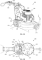
- Figures 1A-1D illustrate views of a floor surfacing machine, such as a floor grinding machine, comprising two drive motors 110, 130.
- a first drive motor 110 is arranged to drive a planetary head 140.
- a second drive motor 130 is arranged to drive a plurality of satellite grinding heads 120.
- a cover 150 protects the planetary head 140 and the satellite grinding heads 120 and allows for dust and debris to be sucked up via an outlet opening 160.
- a forward direction F of the machine 100 is defined as extending away from the handle part 105 which comprises user controls 106 for operating the machine.
- the forward direction F can also be said to be away from the drive wheels 170 of the floor surfacing machine 100.
- a lateral direction extends orthogonal to the forward direction, i.e., orthogonal to an extension plane P of the drive wheels 170, shown in Figure 1B .
- Each wheel support assembly comprises an integrally formed support member 180 configured with a weight to weigh down its wheel 170 against the ground, thereby providing traction to power the machine 100 in the forward direction during floor surfacing.
- the support member 180 has a weight in the range of 15-60 kg, preferably 20-40 kg, and more preferably 23-30 kg, and even more preferably 24-27 kg. In an embodiment the weight is about 26 kg.
- the floor surfacing machine 100 also comprises a support wheel 173 arranged in front of the drive wheels 170.
- Each wheel support assembly 106 also comprises an integrated drive arrangement 190 configured to propel the drive wheels 170.
- the drive arrangement 190 may, e.g., be based on electric motors connected to respective drive wheels 170.
- the floor surfacing machine 100 may be operated by controls on the machine, or remotely via remote control.
- the remote control may be arranged to generate a warning signal in response to an overload condition at a drive motor, as will be further discussed below.
- the wheel support assemblies 106 i.e., the wheel support assembly for the left 171 and the right 172 drive wheel, will be discussed in more detail below in connection to Figures 7-10 .
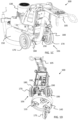
- FIGS 2A and 2B illustrate details of the drive arrangement for driving the satellite grinding heads 120.
- Each satellite grinding head 120 is fixedly attached to a belt pulley 210, which is driven by a belt 220 from a central pulley 260 driven by a motor axle 135 of the second drive motor 130.
- the floor surfacing machine 100 normally comprises three satellite grinding heads 120, but any number of grinding heads can be provided.
- the planetary head 140 is rotated about the motor axle 135 of the second drive motor 130 by the first drive motor 110.
- the direction of rotation R1 of the planetary head 140 and the direction of rotation R2 of the satellite grinding heads are controlled independently from each other, which is an advantage.
- Floor surfacing machines such as the floor surfacing machine 100 with independently operable first and second drive motors were described in US 6,540,596 B1 , and also in SE 539 542 C2 , and will therefore not be discussed in more detail herein.
- the drive arrangements for driving the planetary heads 140 in the type of dual drive arrangements disclosed in US 6,540,596 B1 , and also in SE 539 542 C2 requires maintenance in order to prevent build-up of particles, such as dust, debris, and slurry generated during floor surfacing.
- the drive arrangement for driving the planetary head shown, e.g., in Figure 2B is maintenance free or at least almost maintenance free. This is enabled by way of a protective casing 240 or even a sealed casing arranged to enclose parts of the drive arrangement for driving the planetary head, thereby protecting the drive arrangement from dust, debris, and slurry.
- the protective casing 240 is sealed at its top side against a motor mounting plate 230 to which the first motor 110 is attached.
- the protective casing is also sealed against the floor surfacing machine rotating part 420 by a radial seal which will be discussed in connection to Figures 3 and 4 below.
- the protective casing is a sealed casing with no conduit to an exterior of the casing.
- the casing does not have to be entirely sealed.
- one or more small air-holes may be drilled in the upper part of the casing.
- the protective casing is preferably able to withstand, e.g., high power pressure washing and the like without water penetrating into the interior of the protective casing.
- the first drive motor 110 is arranged to the rear of the floor surfacing machine 100, i.e., between the second drive motor 130 arranged to drive the plurality of satellite grinding heads 120 and the handle part 105 comprising the user controls for operating the machine.
- This location is out of the way and offers some protection for the first drive motor, which is an advantage.
- the protective casing 240 extends from the second drive motor to the rear of the floor surfacing machine 100. The protective casing 240 protects both axles of the first and the second drive motor.
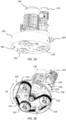
- FIG. 3 shows a cross-sectional view of an example floor surfacing machine drive part comprising the protective casing 240.
- an example drive arrangement 300 for driving a planetary head 140 of a floor surfacing machine 100 comprises a first drive wheel 310 arranged to be driven by the first motor 110.
- a second drive wheel 330 is fixedly attached to the planetary head 140 and arranged to be driven by the first drive wheel via a connecting member 320, such as a chain or a belt.
- the second drive wheel 330 is arranged radially inwards from a motor axle 111 of the first drive motor 110 on the planetary head 140.
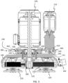
- Figure 4 is a close-up view of the motor axle 135 of the second drive motor 130.
- the second drive wheel 330 is journaled about the motor axle 135 of the second drive motor 130 and bolted 410 to the planetary head, i.e., fixedly attached to the planetary head 140.
- the second drive wheel 330 may of course be fixedly attached to the planetary head 140 in other ways, e.g., by welding.
- the second drive wheel may form part of a direct or indirect gear transmission, or part of a belt drive arrangement, just to name a few examples.
- the rotatable planetary head 140 assembly bears against the non-rotating parts of the floor surfacing machine 100, e.g., by ball-bearings 430.
- the protective casing 240 here comprises a sheet material enclosure arranged to be sealed against a rotating part 420 of the floor surfacing machine 100 by a radial seal 350 arranged around a motor axle 135 of a second drive motor 130 arranged to drive at least one satellite grinding head 120.
- the rotating part 420 comprises the planetary head 140 and the satellite grinding heads 120.
- the protective casing 240 on the other hand is part of a stationary part 440 of the floor surfacing machine, i.e., a part that does not rotate along with the planetary head 140 during operation.
- the stationary part 440 also comprises, e.g., the drive motors 110, 130, the mounting plate 230, and the handle part 105.
- the rotating part 420 bears against the stationary part 440.
- the rotating part 420 rotates relative to the stationary part.
- the rotating part 420 comprises the satellite grinding heads 120 which bear against the rotating part.
- Figure 5 shows a schematic top view of a drive arrangement 300.
- the first drive wheel 310 may be about 100mm in diameter, while the second drive wheel 330 may be about 300mm in diameter.
- the diameter D1 of the first drive wheel 310 is smaller than the diameter D2 of the second drive wheel 330. This way a power ratio is provided by the drive arrangement.
- the first 310 and second 330 drive wheels are sprockets configured to engage the drive chain to bring the planetary head into the rotation R1.
- the drive chain is a self-lubricating chain. This further reduces the maintenance need of the drive arrangement, since the self-lubricating drive chain can be designed to last the entire excepted lifetime of the floor surfacing machine 100.
- the protective casing 240 can be designed to hold an amount of lubricating agent, e.g., lubricating oil.
- the drive chain is a double chain.
- a double chain may be required in order to withstand the requirements on torque imposed on the drive arrangements.
- a double chain may prolong lifetime of the floor surfacing machine.
- the first 310 and second 330 drive wheels are belt pulleys configured to engage the drive belt to bring the planetary head into the rotation R1.
- Figures 6A and 6B show schematic top views of aspects of another drive arrangement 300'.
- the connecting member 320 is a geared connection, i.e., a direct gear connection between the first 310 and second 330 drive wheels or a gear train comprising one or more gears 610, 620.
- the geared connection may be part of a gear transmission arrangement.
- the geared connecting member also provides a power ratio.
- the connecting member 320 comprises a gear train 610, 620 arranged to transfer power from the first motor 110 to the second drive wheel 330.
- the gear train may be part of a gear transmission system, i.e., can be configured with a given gear ratio.
- the floor surfacing machine 100 optionally comprises a first geared drive wheel 310 arranged to be driven by the first drive motor 110 and a second geared drive wheel 330 fixedly attached to the planetary head 140.
- the first drive wheel directly or indirectly engages with the second drive wheel to form the connecting member 320.
- the geared connection may be lubricated by the agent, thus providing extended service interval, since the lubricating agent is protected from outside contamination.
- lubricating agent e.g., lubricating oil
- the drive arrangements 300, 300' also comprise the protective casing 240 which is arranged to enclose the first drive wheel and the second drive wheel 330, and also the connecting member 320, thereby protecting the drive arrangement 300 from dust, debris, and slurry.
- the protective casing is a sealed casing without access from the outside. Since the drive arrangement is protected from the outside, there will be no build-up of particles inside the drive arrangement, and corrosion will be reduced, which is an advantage.
- the protective casing 240 comprises a sheet material enclosure arranged to be sealed against a rotating part of the floor surfacing machine 100 by a radial seal 350.
- the sheet material may be, e.g., sheet metal which is both durable and provides a cost effective seal against outside debris.
- the protective casing 240 may comprise a sheet material enclosure arranged to be sealed against a motor mounting plate 230 to which the first motor 110 is attached.
- the protective casing 240 may be attached to the motor mounting plate 230 by at least one sealing screw 250, thereby providing an improved seal with extended lifetime.
- a seal between the protective casing 240 and the motor mounting plate 230 comprises a foam seal 360 arranged circumferentially along a rim of the protective casing 240.
- Figure 4 shows details of the drive arrangement, i.e., is a zoomed in view of details in Figure 3 .
- the radial seal 350 is illustrated.
- bolts 410 used to attach the second drive wheel to the planetary head are shown in detail.
- the disclosed drive arrangements provide reduced problems with dust intrusion, misalignment of sprocket to welded chain ring and adjustment/mounting difficulties.
- the new drive arrangements disclosed herein may comprise machined components with good control over alignment, and a protective casing (using a radial seal and gasket) which eliminates dust intrusion.
- the new design provides for a simplified tensioning and mounting of a drive chain.
- the first motor may be configured for generating a power in the range 2-2,5 kW, at about 1400 rpm, based on an inverter controlled 3-phase motor.
- the first motor may be attached to a gearbox providing a gear ratio of between 1:10 and 1:25, depending on the transmission ratio in the drive arrangement.
- the transmission ratio between the first drive wheel 310 and the second drive wheel 330 may be in the range 3:1 to 5:1, where the first drive wheel is the smaller wheel of the two.
- the first motor 110 may be a 2,2 kW, 1430 rpm motor providing 14,5 Nm at 50 Hz.
- the gearbox ratio from the first motor drive shaft to the planetary head may be about 1:74.
- the second motor 130 may be configured for generating a power in the range 10-20 kW, and preferably about 11 kW or 15 kW. According to an example, the second motor 130 may be an 11kW or 15 kW motor.
- a center to center distance between drive shafts of the first and second motor may be about 275 mm, in order to fit both motors and a gearbox of the first motor.
- the drive arrangement 300, 300' includes the first drive wheel 310 arranged to be driven by the first drive motor 110, and the second drive wheel 330 fixedly attached to the planetary head 140 and arranged to be driven by the first drive wheel 310.
- the second drive wheel 330 is arranged radially inwards from the first motor axle 111 of the first drive motor 110 relative to a rotational axis of a second motor axle 135 of the second drive motor 130.
- the second drive wheel 330 is provided with a central aperture encircling the second motor axle 135, and the second drive wheel 330 is arranged coaxial with the second motor axle 135 and arranged rotatable relative to the second motor axle 135.
- the central aperture preferably has a circular shape, but may take other forms.
- the rotational axes for the first drive wheel 310 and the second drive wheel 330 are parallel and the first drive wheel 310 and the second drive wheel 330 are arranged in a common plane, wherein said plane is arranged perpendicular to said rotational axes.
- the drive arrangement 300, 300' includes the connecting member 320, such that the second drive wheel 330 is driven by the first drive wheel 330 via said connecting member 320.
- the first drive wheel 330 directly engaging the second drive wheel 330, i.e such that the drive arrangement does not include the connecting member 320.
- the diameter of the central aperture of the second drive wheel 330 is greater than a shortest distance between the aperture and the periphery of the second drive wheel 330 along a radius of the second drive wheel 330.
- the second drive wheel 330 is attached to the planetary head by fastening means 410.
- the fastening means 410 engages the second drive wheel 330 at a position between the periphery of the central aperture and the periphery of the second drive wheel 330, and preferably at a position in the vicinity of the periphery of the central aperture.
- the fastening means are typically in the form of one or several bolts, screws or welds.
- the fastening means may be a combination of different fastening means, such as both screws and welds.
- the drive arrangement 300, 300' is sealingly encapsulated and thereby separated from the drive arrangement for driving the satellite heads 120.
- FIGS 7-10 illustrate details of a wheel support assembly 106 for a floor surfacing machine 100.
- the wheel support assembly 106 comprises an integrally formed support member 180 configured with a weight sufficient to weigh down an attachable wheel, i.e., a drive wheel 170 of the floor surfacing machine, against a ground plane 730.
- the support member 180 has a weight in the range of 15-60 kg, and preferably 20-40 kg, more preferably 23-30kg, and even more preferably 24-27 kg, such as about 26 kg.
- the drive wheels 170 of the floor surfacing machine 100 are weighted down to provide traction.
- the weight comprised in the support member is well positioned to provide traction. Weights arranged more distant from the wheel would not be as effective in providing increased traction.
- the support member 180 may, for example, be integrally formed in cast iron or molded steel.
- FIGs 8 and 9 illustrate how a drive wheel 170 is attached to the support member 180.
- the integrally formed support member 180 comprises a seat 910 for receiving a wheel bearing 1010 (best seen in Figure 10 ) of the attachable wheel 170. Since the wheel bears against the seat 910, the wheel axle is spared from supporting the full weight of the floor surfacing machine 100. With reference to Figure 10 , the force from the ground plane 730 is guided up through the wheel 170 and via the bearing 1010 into the support member 180. The wheel axle 175 is thus spared from supporting the full weight of the floor surfacing machine 100.
- the wheel support assembly 106 may according to some aspects be arranged displaceable 810 along a lateral displacement direction L, as shown in Figures 8 and 9 , with respect to a longitudinal direction P of the attachable wheel 170.
- the support member 180 is arranged to be fixed 820 at two or more different lateral displacements. This is exemplified by bolt holes 820 in Figures 8 and 9 , but may also be achieved using, e.g., a clamping arrangement or the like.
- the wheel support assembly 106 comprises an integrated drive arrangement 190 arranged to drive the attached wheel 170 by a drive unit 710 via a connecting member 720.
- an axle 715 of the drive unit 710 is parallelly displaced from an axle 175 of the attachable wheel 170. This way the drive unit 710 can be moved away from the ground plane 730 to a place where it is somewhat sheltered compared to the case where the drive unit is arranged coaxially with the wheel axle.
- the drive unit 710 may, e.g., be an electric motor connected to the wheel via a gear transmission or belt drive.
- the drive unit 710 may be arranged at an angle A from an axle 175 of the attachable wheel 170 with respect to a ground plane 730 normal 735.
- the angle A can be configured different compared to the angle A for a right wheel 172 support assembly.
- one drive wheel unit can be angled in the forward direction and one drive wheel unit can be angled in the opposite direction. This type of drive unit angle configuration is exemplified in Figure 1D .
- the floor surfacing machine 100 then comprises one or more sensors or systems for detecting an overload condition at least at the first drive motor 110 and/or at the second drive motor 130.
- the system may include a control unit for receiving information from said sensors, and based on said information determining whether the overload condition has been met.
- the overload condition may include that the amount of current consumed by a motor is higher than a threshold current value.
- a warning signal may be triggered.
- the warning signal may appear either on a display as e.g. a pop up message or via signaling means such as warning lights in connection to the floor surfacing machine 100.
- the warning signal may also be generated or displayed on a remote control for remotely controlling the floor surfacing machine 100.
- the warning signal may include information regarding which of the motors for which the overload condition has been met.
- the warning signal is indicative on which of the first- 110 and the second motors 130 that has reached an overload condition.
- a warning signal is generated initially when overload is detected. In case the overload condition persists despite having triggered the warning signal, then an emergency stop may be triggered, or an automatic reduction in applied grinding force in order to reduce load on the first and/or second drive motor.
Landscapes
- Engineering & Computer Science (AREA)
- Mechanical Engineering (AREA)
- General Engineering & Computer Science (AREA)
- Finish Polishing, Edge Sharpening, And Grinding By Specific Grinding Devices (AREA)
- Grinding Of Cylindrical And Plane Surfaces (AREA)
- Connection Of Motors, Electrical Generators, Mechanical Devices, And The Like (AREA)
- Catching Or Destruction (AREA)
- Constituent Portions Of Griding Lathes, Driving, Sensing And Control (AREA)
Abstract
Description
- There are disclosed herein drive arrangements for driving a planetary head of a floor surfacing or grinding machine. The floor surfacing machines described herein are suitable for grinding and polishing hard floor surfaces such as concrete floor surfaces.
- A floor surfacing or grinding machine is commonly used to strip or smooth flooring by grinding away undesired material. Floor surfacing machines provide clean, smooth and essentially flat surfaces to which new coverings or coatings can be applied. Floor surfacing machines are also commonly used to smooth rough flooring surfaces or to remove surface levelling compounds to create a floor which has a smooth, level surface. Certain surfaces, including some types of concrete, are also suitable for polishing using a floor surfacing machine. One common type of a floor surfacing machine is the planetary-type machine. This type of machine normally comprises two to four, or even more, satellite grinding heads mounted within a larger planetary head, where the satellite grinding heads may be driven in one direction and the planetary head in another direction. A motor, normally an electrical motor, drives both the satellite grinding heads and the planetary head, where transmission is accomplished by means of transmission belts and belt pulleys.
- Some floor grinding machines comprise a first motor arranged to drive the planetary head, and a second motor arranged to drive the satellite grinding heads.
-
US 6,540,596 B1 andWO 2008/069748 A1 both disclose surfacing machines with two drive motors. -
EP 1 941 823 A2 discloses a surfacing machine with one motor to drive the planetary head and a plurality of separate motors arranged to drive the satellite grinding heads. - It is an object of the present disclosure to provide improved surfacing machines.
- This object is obtained by a wheel support assembly for a floor surfacing machine. The wheel support assembly comprises an integrally formed support member configured with a weight to weigh down an attachable wheel against a ground plane. The support member has a weight in the range of 15-60 kg, preferably 20-40 kg, and more preferably 23-30 kg, and even more preferably 24-27 kg.
- The support member configuration spares the drive wheel axle from supporting the full weight of the floor surfacing machine, which weight is now instead mostly handled via the supporting member. The support member may, e.g., be integrally formed in cast iron or molded steel.
- According to aspects, the wheel support assembly is arranged displaceable along a lateral displacement direction L with respect to a longitudinal direction P of the attachable wheel. The support member is arranged to be fixed at two or more different lateral displacements. This way the wheel support assembly may accommodate planetary heads of different diameters, providing for a versatile wheel support assembly.
- According to aspects, the wheel support assembly comprises an integrated drive arrangement arranged to drive the attached wheel by a drive unit via a connecting member. An axle of the drive unit may be parallelly displaced from an axle of the attachable wheel. By moving the drive unit away from the wheel axle, the drive unit can be positioned further from the ground plane where it is more protected.
- According to aspects, the drive unit is arranged at an angle from an axle of the attachable wheel with respect to a ground plane normal. Thus, if the wheel support assembly is a left wheel support assembly, the angle can be made different compared to the angle for a right wheel support assembly. This way the drive units become displaced in relation to each other, which allows them to coexist in a small volume. Generally, all terms used in the claims are to be interpreted according to their ordinary meaning in the technical field, unless explicitly defined otherwise herein. All references to "a/an/the element, apparatus, component, means, step, etc." are to be interpreted openly as referring to at least one instance of the element, apparatus, component, means, step, etc., unless explicitly stated otherwise. The steps of any method disclosed herein do not have to be performed in the exact order disclosed, unless explicitly stated. Further features of, and advantages with, the present invention will become apparent when studying the appended claims and the following description. The skilled person realizes that different features of the present invention may be combined to create embodiments other than those described in the following, without departing from the scope of the present invention.
- The present disclosure will now be described more in detail with reference to the appended drawings, where:
- Figures 1A-D
- illustrate views of an example floor surfacing machine.
- Figures 2-3
- show details of example floor surfacing machines;
- Figure 4
- shows details of an example drive arrangement;
- Figures 5-6
- schematically illustrate an example drive arrangements; and
- Figures 7-10
- illustrate example wheel support assemblies.
- The invention will now be described more fully hereinafter with reference to the accompanying drawings, in which certain aspects of the invention are shown. This invention may, however, be embodied in many different forms and should not be construed as limited to the embodiments and aspects set forth herein; rather, these embodiments are provided by way of example so that this disclosure will be thorough and complete, and will fully convey the scope of the invention to those skilled in the art. Like numbers refer to like elements throughout the description.
-
Figures 1A-1D illustrate views of a floor surfacing machine, such as a floor grinding machine, comprising twodrive motors first drive motor 110 is arranged to drive aplanetary head 140. Asecond drive motor 130 is arranged to drive a plurality ofsatellite grinding heads 120. Acover 150 protects theplanetary head 140 and thesatellite grinding heads 120 and allows for dust and debris to be sucked up via an outlet opening 160. - A forward direction F of the
machine 100 is defined as extending away from thehandle part 105 which comprisesuser controls 106 for operating the machine. The forward direction F can also be said to be away from thedrive wheels 170 of thefloor surfacing machine 100. A lateral direction extends orthogonal to the forward direction, i.e., orthogonal to an extension plane P of thedrive wheels 170, shown inFigure 1B . - The left 171 and right 172 drive wheels of the
machine 100 are attached via respectivewheel support assemblies 106. Each wheel support assembly comprises an integrally formedsupport member 180 configured with a weight to weigh down itswheel 170 against the ground, thereby providing traction to power themachine 100 in the forward direction during floor surfacing. To provide enough traction, thesupport member 180 has a weight in the range of 15-60 kg, preferably 20-40 kg, and more preferably 23-30 kg, and even more preferably 24-27 kg. In an embodiment the weight is about 26 kg. - The
floor surfacing machine 100 also comprises asupport wheel 173 arranged in front of thedrive wheels 170. - Each
wheel support assembly 106 also comprises an integrateddrive arrangement 190 configured to propel thedrive wheels 170. Thedrive arrangement 190 may, e.g., be based on electric motors connected torespective drive wheels 170. - The
floor surfacing machine 100 may be operated by controls on the machine, or remotely via remote control. The remote control may be arranged to generate a warning signal in response to an overload condition at a drive motor, as will be further discussed below. - The
wheel support assemblies 106, i.e., the wheel support assembly for the left 171 and the right 172 drive wheel, will be discussed in more detail below in connection toFigures 7-10 . -
Figures 2A and 2B illustrate details of the drive arrangement for driving the satellite grinding heads 120. Eachsatellite grinding head 120 is fixedly attached to abelt pulley 210, which is driven by abelt 220 from acentral pulley 260 driven by amotor axle 135 of thesecond drive motor 130. Thefloor surfacing machine 100 normally comprises threesatellite grinding heads 120, but any number of grinding heads can be provided. - The
planetary head 140 is rotated about themotor axle 135 of thesecond drive motor 130 by thefirst drive motor 110. The direction of rotation R1 of theplanetary head 140 and the direction of rotation R2 of the satellite grinding heads are controlled independently from each other, which is an advantage. - Floor surfacing machines such as the
floor surfacing machine 100 with independently operable first and second drive motors were described inUS 6,540,596 B1 , and also inSE 539 542 C2 - However, the drive arrangements for driving the
planetary heads 140 in the type of dual drive arrangements disclosed inUS 6,540,596 B1 , and also inSE 539 542 C2 - The drive arrangement for driving the planetary head shown, e.g., in
Figure 2B is maintenance free or at least almost maintenance free. This is enabled by way of aprotective casing 240 or even a sealed casing arranged to enclose parts of the drive arrangement for driving the planetary head, thereby protecting the drive arrangement from dust, debris, and slurry. Theprotective casing 240 is sealed at its top side against amotor mounting plate 230 to which thefirst motor 110 is attached. The protective casing is also sealed against the floor surfacingmachine rotating part 420 by a radial seal which will be discussed in connection toFigures 3 and4 below. - According to some aspects the protective casing is a sealed casing with no conduit to an exterior of the casing. However, the casing does not have to be entirely sealed. For instance, one or more small air-holes may be drilled in the upper part of the casing. However, the protective casing is preferably able to withstand, e.g., high power pressure washing and the like without water penetrating into the interior of the protective casing.
- With reference to
Figure 1A , thefirst drive motor 110 is arranged to the rear of thefloor surfacing machine 100, i.e., between thesecond drive motor 130 arranged to drive the plurality of satellite grinding heads 120 and thehandle part 105 comprising the user controls for operating the machine. This location is out of the way and offers some protection for the first drive motor, which is an advantage. Theprotective casing 240 extends from the second drive motor to the rear of thefloor surfacing machine 100. Theprotective casing 240 protects both axles of the first and the second drive motor. -
Figure 3 shows a cross-sectional view of an example floor surfacing machine drive part comprising theprotective casing 240. In particular, there is illustrated anexample drive arrangement 300 for driving aplanetary head 140 of afloor surfacing machine 100. Thedrive arrangement 300 comprises afirst drive wheel 310 arranged to be driven by thefirst motor 110. Asecond drive wheel 330 is fixedly attached to theplanetary head 140 and arranged to be driven by the first drive wheel via a connectingmember 320, such as a chain or a belt. Note that thesecond drive wheel 330 is arranged radially inwards from amotor axle 111 of thefirst drive motor 110 on theplanetary head 140. -
Figure 4 is a close-up view of themotor axle 135 of thesecond drive motor 130. Note that thesecond drive wheel 330 is journaled about themotor axle 135 of thesecond drive motor 130 and bolted 410 to the planetary head, i.e., fixedly attached to theplanetary head 140. Thesecond drive wheel 330 may of course be fixedly attached to theplanetary head 140 in other ways, e.g., by welding. Also, as noted below, the second drive wheel may form part of a direct or indirect gear transmission, or part of a belt drive arrangement, just to name a few examples. - The rotatable
planetary head 140 assembly bears against the non-rotating parts of thefloor surfacing machine 100, e.g., by ball-bearings 430. Note also how theprotective casing 240 here comprises a sheet material enclosure arranged to be sealed against arotating part 420 of thefloor surfacing machine 100 by aradial seal 350 arranged around amotor axle 135 of asecond drive motor 130 arranged to drive at least onesatellite grinding head 120. Therotating part 420 comprises theplanetary head 140 and the satellite grinding heads 120. Theprotective casing 240 on the other hand is part of astationary part 440 of the floor surfacing machine, i.e., a part that does not rotate along with theplanetary head 140 during operation. Thestationary part 440 also comprises, e.g., thedrive motors plate 230, and thehandle part 105. Therotating part 420 bears against thestationary part 440. Therotating part 420 rotates relative to the stationary part. Therotating part 420 comprises the satellite grinding heads 120 which bear against the rotating part. -
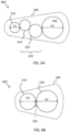
Figure 5 shows a schematic top view of adrive arrangement 300. Thefirst drive wheel 310 may be about 100mm in diameter, while thesecond drive wheel 330 may be about 300mm in diameter. Thus, the diameter D1 of thefirst drive wheel 310 is smaller than the diameter D2 of thesecond drive wheel 330. This way a power ratio is provided by the drive arrangement. - In case a drive chain is used, the first 310 and second 330 drive wheels are sprockets configured to engage the drive chain to bring the planetary head into the rotation R1.
- According to some aspects, the drive chain is a self-lubricating chain. This further reduces the maintenance need of the drive arrangement, since the self-lubricating drive chain can be designed to last the entire excepted lifetime of the
floor surfacing machine 100. - In case a normal chain is used, the
protective casing 240 can be designed to hold an amount of lubricating agent, e.g., lubricating oil. - According to some aspects, the drive chain is a double chain. A double chain may be required in order to withstand the requirements on torque imposed on the drive arrangements. A double chain may prolong lifetime of the floor surfacing machine.
- In case a drive belt is used, the first 310 and second 330 drive wheels are belt pulleys configured to engage the drive belt to bring the planetary head into the rotation R1.
-
Figures 6A and 6B show schematic top views of aspects of another drive arrangement 300'. Here the connectingmember 320 is a geared connection, i.e., a direct gear connection between the first 310 and second 330 drive wheels or a gear train comprising one ormore gears member 320 comprises agear train first motor 110 to thesecond drive wheel 330. The gear train may be part of a gear transmission system, i.e., can be configured with a given gear ratio. - To summarize, the
floor surfacing machine 100 optionally comprises a first geareddrive wheel 310 arranged to be driven by thefirst drive motor 110 and a second geareddrive wheel 330 fixedly attached to theplanetary head 140. The first drive wheel directly or indirectly engages with the second drive wheel to form the connectingmember 320. - In case the
protective casing 240 is arranged to hold an amount of lubricating agent, e.g., lubricating oil, the geared connection may be lubricated by the agent, thus providing extended service interval, since the lubricating agent is protected from outside contamination. - The
drive arrangements 300, 300' also comprise theprotective casing 240 which is arranged to enclose the first drive wheel and thesecond drive wheel 330, and also the connectingmember 320, thereby protecting thedrive arrangement 300 from dust, debris, and slurry. According to some aspects the protective casing is a sealed casing without access from the outside. Since the drive arrangement is protected from the outside, there will be no build-up of particles inside the drive arrangement, and corrosion will be reduced, which is an advantage. - According to some aspects, the
protective casing 240 comprises a sheet material enclosure arranged to be sealed against a rotating part of thefloor surfacing machine 100 by aradial seal 350. The sheet material may be, e.g., sheet metal which is both durable and provides a cost effective seal against outside debris. - The
protective casing 240 may comprise a sheet material enclosure arranged to be sealed against amotor mounting plate 230 to which thefirst motor 110 is attached. - Also, the
protective casing 240 may be attached to themotor mounting plate 230 by at least one sealingscrew 250, thereby providing an improved seal with extended lifetime. - According to some aspects, a seal between the
protective casing 240 and themotor mounting plate 230 comprises afoam seal 360 arranged circumferentially along a rim of theprotective casing 240. -
Figure 4 shows details of the drive arrangement, i.e., is a zoomed in view of details inFigure 3 . In particular, theradial seal 350 is illustrated. Also,bolts 410 used to attach the second drive wheel to the planetary head are shown in detail. - The disclosed drive arrangements provide reduced problems with dust intrusion, misalignment of sprocket to welded chain ring and adjustment/mounting difficulties. The new drive arrangements disclosed herein may comprise machined components with good control over alignment, and a protective casing (using a radial seal and gasket) which eliminates dust intrusion.
- Also, the new design provides for a simplified tensioning and mounting of a drive chain.
- The first motor may be configured for generating a power in the range 2-2,5 kW, at about 1400 rpm, based on an inverter controlled 3-phase motor. The first motor may be attached to a gearbox providing a gear ratio of between 1:10 and 1:25, depending on the transmission ratio in the drive arrangement.
- The transmission ratio between the
first drive wheel 310 and thesecond drive wheel 330 may be in the range 3:1 to 5:1, where the first drive wheel is the smaller wheel of the two. - According to an example, the
first motor 110 may be a 2,2 kW, 1430 rpm motor providing 14,5 Nm at 50 Hz. The gearbox ratio from the first motor drive shaft to the planetary head may be about 1:74. - The
second motor 130 may be configured for generating a power in the range 10-20 kW, and preferably about 11 kW or 15 kW. According to an example, thesecond motor 130 may be an 11kW or 15 kW motor. - A center to center distance between drive shafts of the first and second motor may be about 275 mm, in order to fit both motors and a gearbox of the first motor.
- According to aspects the
drive arrangement 300, 300' includes thefirst drive wheel 310 arranged to be driven by thefirst drive motor 110, and thesecond drive wheel 330 fixedly attached to theplanetary head 140 and arranged to be driven by thefirst drive wheel 310. Thesecond drive wheel 330 is arranged radially inwards from thefirst motor axle 111 of thefirst drive motor 110 relative to a rotational axis of asecond motor axle 135 of thesecond drive motor 130. And, thesecond drive wheel 330 is provided with a central aperture encircling thesecond motor axle 135, and thesecond drive wheel 330 is arranged coaxial with thesecond motor axle 135 and arranged rotatable relative to thesecond motor axle 135. The central aperture preferably has a circular shape, but may take other forms. - According to further aspects, the rotational axes for the
first drive wheel 310 and thesecond drive wheel 330 are parallel and thefirst drive wheel 310 and thesecond drive wheel 330 are arranged in a common plane, wherein said plane is arranged perpendicular to said rotational axes. - Preferably, the
drive arrangement 300, 300' includes the connectingmember 320, such that thesecond drive wheel 330 is driven by thefirst drive wheel 330 via said connectingmember 320. However, it is conceivable to have thefirst drive wheel 330 directly engaging thesecond drive wheel 330, i.e such that the drive arrangement does not include the connectingmember 320. - Preferably, the diameter of the central aperture of the
second drive wheel 330 is greater than a shortest distance between the aperture and the periphery of thesecond drive wheel 330 along a radius of thesecond drive wheel 330. - According to aspects, the
second drive wheel 330 is attached to the planetary head by fastening means 410. The fastening means 410 engages thesecond drive wheel 330 at a position between the periphery of the central aperture and the periphery of thesecond drive wheel 330, and preferably at a position in the vicinity of the periphery of the central aperture. The fastening means are typically in the form of one or several bolts, screws or welds. The fastening means may be a combination of different fastening means, such as both screws and welds. - Preferably, the
drive arrangement 300, 300' is sealingly encapsulated and thereby separated from the drive arrangement for driving the satellite heads 120. -
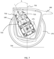
Figures 7-10 illustrate details of awheel support assembly 106 for afloor surfacing machine 100. Thewheel support assembly 106 comprises an integrally formedsupport member 180 configured with a weight sufficient to weigh down an attachable wheel, i.e., adrive wheel 170 of the floor surfacing machine, against aground plane 730. Thesupport member 180 has a weight in the range of 15-60 kg, and preferably 20-40 kg, more preferably 23-30kg, and even more preferably 24-27 kg, such as about 26 kg. - By integrating the weight into the
support member 180, thedrive wheels 170 of thefloor surfacing machine 100 are weighted down to provide traction. The weight comprised in the support member is well positioned to provide traction. Weights arranged more distant from the wheel would not be as effective in providing increased traction. Thesupport member 180 may, for example, be integrally formed in cast iron or molded steel. -
Figures 8 and 9 illustrate how adrive wheel 170 is attached to thesupport member 180. The integrally formedsupport member 180 comprises aseat 910 for receiving a wheel bearing 1010 (best seen inFigure 10 ) of theattachable wheel 170. Since the wheel bears against theseat 910, the wheel axle is spared from supporting the full weight of thefloor surfacing machine 100. With reference toFigure 10 , the force from theground plane 730 is guided up through thewheel 170 and via thebearing 1010 into thesupport member 180. Thewheel axle 175 is thus spared from supporting the full weight of thefloor surfacing machine 100. - To accommodate different diameters of, e.g., the
planetary head 140, thewheel support assembly 106 may according to some aspects be arranged displaceable 810 along a lateral displacement direction L, as shown inFigures 8 and 9 , with respect to a longitudinal direction P of theattachable wheel 170. Thesupport member 180 is arranged to be fixed 820 at two or more different lateral displacements. This is exemplified by bolt holes 820 inFigures 8 and 9 , but may also be achieved using, e.g., a clamping arrangement or the like. - According to some aspects, the
wheel support assembly 106 comprises anintegrated drive arrangement 190 arranged to drive the attachedwheel 170 by adrive unit 710 via a connectingmember 720. With reference toFigure 10 , anaxle 715 of thedrive unit 710 is parallelly displaced from anaxle 175 of theattachable wheel 170. This way thedrive unit 710 can be moved away from theground plane 730 to a place where it is somewhat sheltered compared to the case where the drive unit is arranged coaxially with the wheel axle. - The
drive unit 710, may, e.g., be an electric motor connected to the wheel via a gear transmission or belt drive. - To save space under the
machine 100, and simplify access to, e.g., theoutlet opening 160, with reference toFigure 7 , thedrive unit 710 may be arranged at an angle A from anaxle 175 of theattachable wheel 170 with respect to aground plane 730 normal 735. This way, if thewheel support assembly 106 is aleft wheel 171 support assembly, the angle A can be configured different compared to the angle A for aright wheel 172 support assembly. For instance, one drive wheel unit can be angled in the forward direction and one drive wheel unit can be angled in the opposite direction. This type of drive unit angle configuration is exemplified inFigure 1D . - Aspects of the disclosure also relates to a system for motor overload warning. The
floor surfacing machine 100 then comprises one or more sensors or systems for detecting an overload condition at least at thefirst drive motor 110 and/or at thesecond drive motor 130. The system may include a control unit for receiving information from said sensors, and based on said information determining whether the overload condition has been met. As an example, the overload condition may include that the amount of current consumed by a motor is higher than a threshold current value. In case overload is detected a warning signal may be triggered. The warning signal may appear either on a display as e.g. a pop up message or via signaling means such as warning lights in connection to thefloor surfacing machine 100. The warning signal may also be generated or displayed on a remote control for remotely controlling thefloor surfacing machine 100. The warning signal may include information regarding which of the motors for which the overload condition has been met. Preferably, the warning signal is indicative on which of the first- 110 and thesecond motors 130 that has reached an overload condition. - According to aspects, a warning signal is generated initially when overload is detected. In case the overload condition persists despite having triggered the warning signal, then an emergency stop may be triggered, or an automatic reduction in applied grinding force in order to reduce load on the first and/or second drive motor.
Claims (12)
- A wheel support assembly (106) for a floor surfacing machine (100), the wheel support assembly (106) comprising an integrally formed support member (180) configured with a weight to weigh down an attachable wheel (170) against a ground plane (730), wherein the support member (180) has a weight in the range of 15-60 kg, and preferably 20-40 kg, and more preferably 23-30 kg.
- The wheel support assembly (106) according to claim 1, wherein the support member (180) is integrally formed in cast iron.
- The wheel support assembly (106) according to any one of the preceding claims, wherein the integrally formed support member (180) comprises a seat (910) for receiving a wheel bearing (1010) of the attachable wheel (170).
- The wheel support assembly (106) according to any one of the preceding claims, arranged displaceable (810) along a lateral displacement direction (L) with respect to a longitudinal direction (P) of the attachable wheel (170), wherein the support member (180) is arranged to be fixable (820) at two or more different lateral displacements.
- The wheel support assembly (106) according to any one of the preceding claims, comprising an integrated drive arrangement (190) arranged to drive the attached wheel (170) by a drive unit (710) via a connecting member (720).
- The wheel support assembly (106) according to claim 5, wherein an axle (715) of the drive unit (710) is parallelly displaced from an axle (175) of the attachable wheel (170).
- The wheel support assembly (106) according to claim 5 or 6, wherein the drive unit (710) is an electric motor.
- The wheel support assembly (106) according to any one of the claims 5-7, wherein the connecting member (720) comprises a gear transmission.
- The wheel support assembly (106) according to any one of the claims 5-8, wherein the drive unit (710) is arranged at an angle (A) from an axle (175) of the attachable wheel (170) with respect to a ground plane (730) normal (735).
- The wheel support assembly (106) according to claim 9, wherein, if the wheel support assembly (106) is a left wheel (171) support assembly, the angle A is different compared to the angle A for a right wheel (172) support assembly.
- A floor surfacing machine (100) comprising the wheel support assembly (106) according to any one of the preceding claims.
- The floor surfacing machine according to claim 11 comprising a drive arrangement (300, 300'), the drive arrangement (300, 300') comprising;a first drive wheel (310) arranged to be driven by a first motor (110),a second drive wheel (330) fixedly attached to the planetary head (140) and arranged to be driven by the first drive wheel (310),a second drive motor (130) arranged to drive at least one satellite grinding head (120),wherein in the second drive wheel (330) is journaled about and coaxial with a motor axle (135) of the second drive motor (130).
Applications Claiming Priority (3)
| Application Number | Priority Date | Filing Date | Title |
|---|---|---|---|
| SE1950959A SE543257C2 (en) | 2019-08-22 | 2019-08-22 | A drive arrangement for a floor surfacing machine and a floor surfacing machine |
| PCT/SE2020/050565 WO2021034242A1 (en) | 2019-08-22 | 2020-06-04 | A drive arrangement for a floor surfacing machine and a floor surfacing machine |
| EP20853870.2A EP4017680A4 (en) | 2019-08-22 | 2020-06-04 | DRIVE ARRANGEMENT FOR A FLOOR COATING MACHINE AND FLOOR COATING MACHINE |
Related Parent Applications (1)
| Application Number | Title | Priority Date | Filing Date |
|---|---|---|---|
| EP20853870.2A Division EP4017680A4 (en) | 2019-08-22 | 2020-06-04 | DRIVE ARRANGEMENT FOR A FLOOR COATING MACHINE AND FLOOR COATING MACHINE |
Publications (2)
| Publication Number | Publication Date |
|---|---|
| EP4364631A2 true EP4364631A2 (en) | 2024-05-08 |
| EP4364631A3 EP4364631A3 (en) | 2024-06-12 |
Family
ID=73015860
Family Applications (2)
| Application Number | Title | Priority Date | Filing Date |
|---|---|---|---|
| EP20853870.2A Pending EP4017680A4 (en) | 2019-08-22 | 2020-06-04 | DRIVE ARRANGEMENT FOR A FLOOR COATING MACHINE AND FLOOR COATING MACHINE |
| EP24165148.8A Pending EP4364631A3 (en) | 2019-08-22 | 2020-06-04 | A wheel support assembly for a floor surfacing machine |
Family Applications Before (1)
| Application Number | Title | Priority Date | Filing Date |
|---|---|---|---|
| EP20853870.2A Pending EP4017680A4 (en) | 2019-08-22 | 2020-06-04 | DRIVE ARRANGEMENT FOR A FLOOR COATING MACHINE AND FLOOR COATING MACHINE |
Country Status (6)
| Country | Link |
|---|---|
| US (2) | US12269143B2 (en) |
| EP (2) | EP4017680A4 (en) |
| CN (2) | CN114585474A (en) |
| AU (2) | AU2020334701B2 (en) |
| SE (1) | SE543257C2 (en) |
| WO (1) | WO2021034242A1 (en) |
Families Citing this family (2)
| Publication number | Priority date | Publication date | Assignee | Title |
|---|---|---|---|---|
| CN111546160A (en) * | 2020-06-15 | 2020-08-18 | 林鑫森 | A ground leveling grinder |
| WO2026065597A1 (en) * | 2024-09-29 | 2026-04-02 | 福建兴翼智能装备股份有限公司 | Grinding machine gearbox with good sealing effect |
Citations (4)
| Publication number | Priority date | Publication date | Assignee | Title |
|---|---|---|---|---|
| US6540596B1 (en) | 1998-07-06 | 2003-04-01 | Timothy Roelf Van Der Veen | Mobile surfacing machine |
| WO2008069748A1 (en) | 2006-12-06 | 2008-06-12 | Scanmaskin Sverige Ab | Device for driving a grinding machine |
| EP1941823A2 (en) | 2007-01-03 | 2008-07-09 | Holland Industriële Diamantwerken B.V. | Floor treating machine |
| SE539542C2 (en) | 2014-09-25 | 2017-10-10 | Husqvarna Ab | Floor surfacing machine |
Family Cites Families (18)
| Publication number | Priority date | Publication date | Assignee | Title |
|---|---|---|---|---|
| US2301164A (en) * | 1940-05-13 | 1942-11-03 | Mall Arthur William | Floor grinder |
| GB819231A (en) | 1957-05-31 | 1959-09-02 | Hubert Smalley | Improvements in or relating to powered scrubbing, polishing or abrading machines |
| GB822228A (en) | 1958-04-15 | 1959-10-21 | Granell Mfg Ltd | Floor grinding machine |
| IT1216703B (en) * | 1987-11-06 | 1990-03-08 | Dulevo Spa | SCRAPING DEVICE FOR FLOOR AND SURFACE CLEANING MACHINES. |
| NL1014015C2 (en) * | 2000-01-05 | 2001-07-09 | Holland Ind Diamantwerken Bv | Grinding machine for removing top layer from floor, includes main and auxiliary motors for independently setting rotation speeds for grinding heads and their housing |
| NL1015226C2 (en) | 2000-05-17 | 2001-11-22 | Holland Ind Diamantwerken Bv | Floor processing machine. |
| SE518356C2 (en) * | 2001-02-06 | 2002-10-01 | Haakan Thysell | Device for mobile machine for grinding floor surfaces |
| SE525499C2 (en) | 2002-03-12 | 2005-03-01 | Htc Sweden Ab | Device on a mobile machine for grinding floor surfaces |
| US7331636B2 (en) | 2004-10-07 | 2008-02-19 | Prep Engineering, Inc. | Electric milling machine |
| US7247085B1 (en) | 2005-03-15 | 2007-07-24 | National Carpet Equipment, Inc. | Combination edger and grinder for floors |
| ATE423653T1 (en) * | 2005-09-06 | 2009-03-15 | Trumpf Werkzeugmaschinen Gmbh | DEVICE FOR RECEIVING PLATE-SHAPED MATERIALS FOR AT LEAST ONE SEPARATION PROCESS |
| EP2508301B1 (en) | 2011-04-04 | 2014-05-14 | Katdangil, Private Stichting | Apparatus for treating floor surfaces along a wall |
| GB2501747A (en) | 2012-05-03 | 2013-11-06 | Dowding & Plummer Ltd | An apparatus for cleaning a floor surface |
| CN203650160U (en) | 2013-10-30 | 2014-06-18 | 晋江兴翼机械有限公司 | Remote control floor stone grinder |
| CN205342708U (en) | 2016-01-26 | 2016-06-29 | 晋江兴翼机械有限公司 | Grind quick -witted pressure adjustment arm |
| CN205552164U (en) | 2016-04-06 | 2016-09-07 | 晋江兴翼机械有限公司 | Terrace grinds quick -witted runner actuating mechanism |
| SE1651353A1 (en) * | 2016-10-17 | 2018-02-27 | Husqvarna Ab | Safety arrangement and method for a floor surfacing machine |
| SE542032C2 (en) * | 2018-01-18 | 2020-02-11 | Scanmaskin Sverige Ab | A floor grinding machine |
-
2019
- 2019-08-22 SE SE1950959A patent/SE543257C2/en not_active IP Right Cessation
-
2020
- 2020-06-04 CN CN202080073845.7A patent/CN114585474A/en active Pending
- 2020-06-04 CN CN202511744222.9A patent/CN121468324A/en active Pending
- 2020-06-04 EP EP20853870.2A patent/EP4017680A4/en active Pending
- 2020-06-04 WO PCT/SE2020/050565 patent/WO2021034242A1/en not_active Ceased
- 2020-06-04 EP EP24165148.8A patent/EP4364631A3/en active Pending
- 2020-06-04 AU AU2020334701A patent/AU2020334701B2/en active Active
- 2020-06-04 US US17/637,118 patent/US12269143B2/en active Active
-
2025
- 2025-03-11 US US19/075,931 patent/US20250205849A1/en active Pending
- 2025-03-19 AU AU2025201984A patent/AU2025201984A1/en active Pending
Patent Citations (4)
| Publication number | Priority date | Publication date | Assignee | Title |
|---|---|---|---|---|
| US6540596B1 (en) | 1998-07-06 | 2003-04-01 | Timothy Roelf Van Der Veen | Mobile surfacing machine |
| WO2008069748A1 (en) | 2006-12-06 | 2008-06-12 | Scanmaskin Sverige Ab | Device for driving a grinding machine |
| EP1941823A2 (en) | 2007-01-03 | 2008-07-09 | Holland Industriële Diamantwerken B.V. | Floor treating machine |
| SE539542C2 (en) | 2014-09-25 | 2017-10-10 | Husqvarna Ab | Floor surfacing machine |
Also Published As
| Publication number | Publication date |
|---|---|
| EP4364631A3 (en) | 2024-06-12 |
| US20220339756A1 (en) | 2022-10-27 |
| EP4017680A1 (en) | 2022-06-29 |
| AU2020334701B2 (en) | 2025-03-13 |
| CN114585474A (en) | 2022-06-03 |
| AU2020334701A1 (en) | 2022-04-14 |
| US12269143B2 (en) | 2025-04-08 |
| WO2021034242A1 (en) | 2021-02-25 |
| CN121468324A (en) | 2026-02-06 |
| SE1950959A1 (en) | 2020-11-03 |
| SE543257C2 (en) | 2020-11-03 |
| EP4017680A4 (en) | 2023-09-13 |
| AU2025201984A1 (en) | 2025-04-03 |
| US20250205849A1 (en) | 2025-06-26 |
Similar Documents
| Publication | Publication Date | Title |
|---|---|---|
| US20250205849A1 (en) | Drive arrangement for a floor surfacing machine and a floor surfacing machine | |
| CN102975579B (en) | The running driving device of tip car | |
| US5472059A (en) | Wheel end assembly | |
| US20030129035A1 (en) | Workpiece holding means for machine tools and more especially for milling and/or drilling machines | |
| KR101712531B1 (en) | Swing device for construction machine | |
| JP5327754B2 (en) | Automatic road surface cutting device | |
| EP1576286B1 (en) | Wind turbine gear unit with integrated rotor bearing | |
| GB2302850A (en) | Driving axle for an industrial truck | |
| JP2011184040A (en) | Vehicle drive unit for dump truck | |
| JPH1072164A (en) | Flange mounting type cable drum | |
| KR20150005555A (en) | Construction machine drive device | |
| SE1950961A1 (en) | A drive arrangement for a floor surfacing machine and a floor surfacing machine | |
| US4446977A (en) | Roller support for load handling devices | |
| SE1950960A1 (en) | A wheel support assembly for a floor surfacing machine and a floor surfacing machine | |
| JP6011717B2 (en) | In-wheel motor unit for vehicles | |
| KR20040013878A (en) | Turning device for welding of heavy structure | |
| WO2019017789A1 (en) | Dual tyre rim | |
| JP2006264396A (en) | Dump truck travel drive device | |
| CN115370729A (en) | Geared motor having a motor driving a gear reducer | |
| JPS61252939A (en) | planetary gear system | |
| JP5014359B2 (en) | Cooling device for lubricating oil for travel reducer | |
| JP2007002981A (en) | Reduction gear | |
| CN214788945U (en) | Speed reducing motor | |
| WO1999034955A1 (en) | Hydraulic pendulum grinding machine | |
| KR20060091474A (en) | Vehicle deceleration device |
Legal Events
| Date | Code | Title | Description |
|---|---|---|---|
| PUAI | Public reference made under article 153(3) epc to a published international application that has entered the european phase |
Free format text: ORIGINAL CODE: 0009012 |
|
| STAA | Information on the status of an ep patent application or granted ep patent |
Free format text: STATUS: THE APPLICATION HAS BEEN PUBLISHED |
|
| REG | Reference to a national code |
Ref country code: DE Ref legal event code: R079 Free format text: PREVIOUS MAIN CLASS: A47L0011400000 Ipc: B24B0007180000 |
|
| AC | Divisional application: reference to earlier application |
Ref document number: 4017680 Country of ref document: EP Kind code of ref document: P |
|
| AK | Designated contracting states |
Kind code of ref document: A2 Designated state(s): AL AT BE BG CH CY CZ DE DK EE ES FI FR GB GR HR HU IE IS IT LI LT LU LV MC MK MT NL NO PL PT RO RS SE SI SK SM TR |
|
| PUAL | Search report despatched |
Free format text: ORIGINAL CODE: 0009013 |
|
| AK | Designated contracting states |
Kind code of ref document: A3 Designated state(s): AL AT BE BG CH CY CZ DE DK EE ES FI FR GB GR HR HU IE IS IT LI LT LU LV MC MK MT NL NO PL PT RO RS SE SI SK SM TR |
|
| RIC1 | Information provided on ipc code assigned before grant |
Ipc: B24B 41/02 20060101ALI20240503BHEP Ipc: A47L 11/40 20060101ALI20240503BHEP Ipc: A47L 11/14 20060101ALI20240503BHEP Ipc: F16H 57/04 20100101ALI20240503BHEP Ipc: B24B 47/12 20060101ALI20240503BHEP Ipc: B24B 41/047 20060101ALI20240503BHEP Ipc: B24B 7/18 20060101AFI20240503BHEP |
|
| STAA | Information on the status of an ep patent application or granted ep patent |
Free format text: STATUS: REQUEST FOR EXAMINATION WAS MADE |
|
| 17P | Request for examination filed |
Effective date: 20241209 |