EP4364627B1 - Lifting device and cleaning apparatus - Google Patents
Lifting device and cleaning apparatus Download PDFInfo
- Publication number
- EP4364627B1 EP4364627B1 EP23191069.6A EP23191069A EP4364627B1 EP 4364627 B1 EP4364627 B1 EP 4364627B1 EP 23191069 A EP23191069 A EP 23191069A EP 4364627 B1 EP4364627 B1 EP 4364627B1
- Authority
- EP
- European Patent Office
- Prior art keywords
- lifting
- rotating shaft
- lifting device
- traction
- drive portion
- Prior art date
- Legal status (The legal status is an assumption and is not a legal conclusion. Google has not performed a legal analysis and makes no representation as to the accuracy of the status listed.)
- Active
Links
Images




Classifications
-
- A—HUMAN NECESSITIES
- A47—FURNITURE; DOMESTIC ARTICLES OR APPLIANCES; COFFEE MILLS; SPICE MILLS; SUCTION CLEANERS IN GENERAL
- A47L—DOMESTIC WASHING OR CLEANING; SUCTION CLEANERS IN GENERAL
- A47L11/00—Machines for cleaning floors, carpets, furniture, walls, or wall coverings
- A47L11/24—Floor-sweeping machines, motor-driven
-
- A—HUMAN NECESSITIES
- A47—FURNITURE; DOMESTIC ARTICLES OR APPLIANCES; COFFEE MILLS; SPICE MILLS; SUCTION CLEANERS IN GENERAL
- A47L—DOMESTIC WASHING OR CLEANING; SUCTION CLEANERS IN GENERAL
- A47L11/00—Machines for cleaning floors, carpets, furniture, walls, or wall coverings
- A47L11/40—Parts or details of machines not provided for in groups A47L11/02 - A47L11/38, or not restricted to one of these groups, e.g. handles, arrangements of switches, skirts, buffers, levers
- A47L11/4052—Movement of the tools or the like perpendicular to the cleaning surface
- A47L11/4055—Movement of the tools or the like perpendicular to the cleaning surface for lifting the tools to a non-working position
-
- A—HUMAN NECESSITIES
- A47—FURNITURE; DOMESTIC ARTICLES OR APPLIANCES; COFFEE MILLS; SPICE MILLS; SUCTION CLEANERS IN GENERAL
- A47L—DOMESTIC WASHING OR CLEANING; SUCTION CLEANERS IN GENERAL
- A47L1/00—Cleaning windows
- A47L1/02—Power-driven machines or devices
-
- A—HUMAN NECESSITIES
- A47—FURNITURE; DOMESTIC ARTICLES OR APPLIANCES; COFFEE MILLS; SPICE MILLS; SUCTION CLEANERS IN GENERAL
- A47L—DOMESTIC WASHING OR CLEANING; SUCTION CLEANERS IN GENERAL
- A47L11/00—Machines for cleaning floors, carpets, furniture, walls, or wall coverings
- A47L11/28—Floor-scrubbing machines, motor-driven
- A47L11/282—Floor-scrubbing machines, motor-driven having rotary tools
-
- A—HUMAN NECESSITIES
- A47—FURNITURE; DOMESTIC ARTICLES OR APPLIANCES; COFFEE MILLS; SPICE MILLS; SUCTION CLEANERS IN GENERAL
- A47L—DOMESTIC WASHING OR CLEANING; SUCTION CLEANERS IN GENERAL
- A47L11/00—Machines for cleaning floors, carpets, furniture, walls, or wall coverings
- A47L11/28—Floor-scrubbing machines, motor-driven
- A47L11/282—Floor-scrubbing machines, motor-driven having rotary tools
- A47L11/283—Floor-scrubbing machines, motor-driven having rotary tools the tools being disc brushes
-
- A—HUMAN NECESSITIES
- A47—FURNITURE; DOMESTIC ARTICLES OR APPLIANCES; COFFEE MILLS; SPICE MILLS; SUCTION CLEANERS IN GENERAL
- A47L—DOMESTIC WASHING OR CLEANING; SUCTION CLEANERS IN GENERAL
- A47L11/00—Machines for cleaning floors, carpets, furniture, walls, or wall coverings
- A47L11/29—Floor-scrubbing machines characterised by means for taking-up dirty liquid
- A47L11/292—Floor-scrubbing machines characterised by means for taking-up dirty liquid having rotary tools
- A47L11/293—Floor-scrubbing machines characterised by means for taking-up dirty liquid having rotary tools the tools being disc brushes
-
- A—HUMAN NECESSITIES
- A47—FURNITURE; DOMESTIC ARTICLES OR APPLIANCES; COFFEE MILLS; SPICE MILLS; SUCTION CLEANERS IN GENERAL
- A47L—DOMESTIC WASHING OR CLEANING; SUCTION CLEANERS IN GENERAL
- A47L11/00—Machines for cleaning floors, carpets, furniture, walls, or wall coverings
- A47L11/40—Parts or details of machines not provided for in groups A47L11/02 - A47L11/38, or not restricted to one of these groups, e.g. handles, arrangements of switches, skirts, buffers, levers
-
- A—HUMAN NECESSITIES
- A47—FURNITURE; DOMESTIC ARTICLES OR APPLIANCES; COFFEE MILLS; SPICE MILLS; SUCTION CLEANERS IN GENERAL
- A47L—DOMESTIC WASHING OR CLEANING; SUCTION CLEANERS IN GENERAL
- A47L11/00—Machines for cleaning floors, carpets, furniture, walls, or wall coverings
- A47L11/40—Parts or details of machines not provided for in groups A47L11/02 - A47L11/38, or not restricted to one of these groups, e.g. handles, arrangements of switches, skirts, buffers, levers
- A47L11/4036—Parts or details of the surface treating tools
- A47L11/4038—Disk shaped surface treating tools
-
- A—HUMAN NECESSITIES
- A47—FURNITURE; DOMESTIC ARTICLES OR APPLIANCES; COFFEE MILLS; SPICE MILLS; SUCTION CLEANERS IN GENERAL
- A47L—DOMESTIC WASHING OR CLEANING; SUCTION CLEANERS IN GENERAL
- A47L11/00—Machines for cleaning floors, carpets, furniture, walls, or wall coverings
- A47L11/40—Parts or details of machines not provided for in groups A47L11/02 - A47L11/38, or not restricted to one of these groups, e.g. handles, arrangements of switches, skirts, buffers, levers
- A47L11/4052—Movement of the tools or the like perpendicular to the cleaning surface
- A47L11/4058—Movement of the tools or the like perpendicular to the cleaning surface for adjusting the height of the tool
-
- A—HUMAN NECESSITIES
- A47—FURNITURE; DOMESTIC ARTICLES OR APPLIANCES; COFFEE MILLS; SPICE MILLS; SUCTION CLEANERS IN GENERAL
- A47L—DOMESTIC WASHING OR CLEANING; SUCTION CLEANERS IN GENERAL
- A47L11/00—Machines for cleaning floors, carpets, furniture, walls, or wall coverings
- A47L11/40—Parts or details of machines not provided for in groups A47L11/02 - A47L11/38, or not restricted to one of these groups, e.g. handles, arrangements of switches, skirts, buffers, levers
- A47L11/4063—Driving means; Transmission means therefor
- A47L11/4069—Driving or transmission means for the cleaning tools
-
- A—HUMAN NECESSITIES
- A47—FURNITURE; DOMESTIC ARTICLES OR APPLIANCES; COFFEE MILLS; SPICE MILLS; SUCTION CLEANERS IN GENERAL
- A47L—DOMESTIC WASHING OR CLEANING; SUCTION CLEANERS IN GENERAL
- A47L2201/00—Robotic cleaning machines, i.e. with automatic control of the travelling movement or the cleaning operation
-
- A—HUMAN NECESSITIES
- A47—FURNITURE; DOMESTIC ARTICLES OR APPLIANCES; COFFEE MILLS; SPICE MILLS; SUCTION CLEANERS IN GENERAL
- A47L—DOMESTIC WASHING OR CLEANING; SUCTION CLEANERS IN GENERAL
- A47L2201/00—Robotic cleaning machines, i.e. with automatic control of the travelling movement or the cleaning operation
- A47L2201/06—Control of the cleaning action for autonomous devices; Automatic detection of the surface condition before, during or after cleaning
Definitions
- the present application relates to the technical field of cleaning apparatuses, and more particularly to a lifting device and a cleaning apparatus.
- cleaning apparatus with cleaning function is more and more favored by people because of its advantages of convenient cleaning, time-saving and labor-saving.
- a cleaning apparatus has been proposed, the cleaning apparatus is equipped with two drivers, one driver is used to drive the cleaning component to rotate for mopping, and the other one is used to drive the cleaning component to lift, in order to lift the cleaning components to avoid bumps or contamination of carpets and other items when the cleaning apparatus passes by an uneven ground, or when the cleaning apparatus passes by a road where carpets and other items are placed.
- the exemplary technology can effectively improve the practicality of the cleaning apparatus, the volume of the cleaning apparatus is increased due to the installation of two drivers, which is not conducive to the cleaning apparatus into a small space for cleaning operation, based on this, there is an urgent need for those skilled in the art to improve the cleaning apparatus.
- a Chinese Patent application CN217645157 disclosed a lifting and rotating device and a cleaning robot, and the lifting and rotating device comprises a shell, a motor and a lifting and rotating mechanism.
- the shell is provided with an accommodating cavity; the motor is arranged on the shell; the lifting rotating mechanism is arranged in the containing cavity.
- the lifting rotating mechanism comprises a rotating shaft and a lifting shaft assembly.
- the motor drives the rotating shaft to rotate around the shaft, and the lifting shaft assembly is rotationally connected to the shell and can do lifting motion relative to the shell in the axial direction of the lifting shaft assembly.
- the lifting shaft assembly is independent of the rotating shaft, the rotating shaft drives the cleaning piece to rotate.
- the motor rotates in the second preset direction
- the motor rotates to drive the lifting shaft assembly to rotate around the shaft, and meanwhile the lifting shaft assembly ascends and descends relative to the shell so as to drive the shaft body and the cleaning piece to ascend and descend.
- the rotating motion and the lifting motion of the cleaning piece can be completed through one motor, and therefore the lifting and rotating device is more beneficial to miniaturization design of the cleaning robot.
- a main object of the present application is to provide a lifting device, so as to solve the technical problem that the volume of the cleaning apparatus having lifting function in the art is larger.
- the present application provides a lifting device, which includes: a drive motor, a rotating shaft, a transmission assembly, and a traction member;
- the rotating shaft includes a mounting portion and a lifting drive portion connected to the mounting portion, and the mounting portion is configured for connecting with the cleaning component, the cleaning component is configured to clean a surface to be cleaned;
- the transmission assembly is respectively connected to an output end of the drive motor and the rotating shaft, to transfer a power of the drive motor to the rotating shaft;
- the traction member is threaded to the lifting drive portion; when the rotating shaft is rotated in a first rotation direction driven by the drive motor, the lifting drive portion rotates relative to the traction member and the rotating shaft moves in a direction that approaches the surface to be cleaned; and when the rotating shaft is rotated in a second rotation direction opposite to the first rotation direction driven by the drive motor, the lifting drive portion rotates relative to the traction member and the rotating shaft moves in a direction away from the surface to be cleaned.
- a peripheral wall of the lifting drive portion is provided with a thread spirally extending along an axis direction of the lifting drive portion
- the traction member comprises a traction slider arranged on a side of the lifting drive portion, and at least a part of a structure of the traction slider is slidably arranged in a groove of the thread.
- an end of the groove of the thread adjacent to the mounting portion is provided with a limiting structure configured for limiting the traction slider from sliding out of the groove of the thread.
- the lifting device further includes a switch electrically connected with the drive motor, and the switch is configured to be triggered to stop the drive motor; and a triggering position of the switch is arranged on a moving path of the rotating shaft, and the rotating shaft is able to trigger the switch when the lifting drive portion moves in a direction away from the mounting portion.
- the rotating shaft includes a triggering portion projecting from the peripheral wall of the lifting drive portion, and the triggering portion and the thread are spaced away from each other; and the switch is a contact switch, the switch is provided with a button, the button is arranged on a side of the triggering portion facing away from the mounting portion, and triggering portion presses the button when the lifting drive portion moves in a direction away from the mounting portion.
- the triggering portion is a first gear sleeved on the peripheral wall of the lifting drive portion;
- the transmission assembly includes a second gear extending in parallel with the rotating shaft, and the second gear is in a transmission connection with the drive motor, and the second gear is meshed with the first gear.
- a portion of the traction slider located in the groove of the thread is arranged in a cylindrical shape.
- the lifting device includes a first elastic member, the first elastic member is arranged at a side of the lifting drive portion facing away from the mounting portion and connected to the lifting drive portion, to provide a drive force to the lifting drive portion when the lifting drive portion moves in a direction that approaches the surface to be cleaned.
- the lifting device includes a second elastic member, and the second elastic member is arranged at a side of the traction member facing away from the mounting portion and connected to the traction member, to move the traction member along an axis direction of the rotating shaft.
- an elastic coefficient of the first elastic member is greater than or equal to an elastic coefficient of the second elastic member.
- a peripheral wall of the lifting drive portion is provided with a thread spirally extending along an axis direction of the lifting drive portion
- the traction member comprises a traction slider arranged on a side of the lifting drive portion, and at least a part of a structure of the traction slider is slidably arranged in a groove of the thread
- the traction member comprises a mounting housing arranged at a side of the lifting drive portion, the mounting housing is provided with a guide groove extending in a same direction of the lifting drive portion, the guide groove is arranged to have an opening at a side of the mounting housing facing the lifting drive portion, the traction slider is slidably mounted at the guide groove, and a part of a structure of the traction slider is inserted into the groove of the thread through the opening, and at least a part of a structure of the second elastic member is arranged in the guide groove and connected with the traction slider.
- an end of the lifting drive portion facing away from the mounting portion is concavely provided with a mounting groove, at least a part of a structure of the first elastic member is arranged in the mounting groove, and an end of the first elastic member is elastically abutted against a bottom wall of the mounting groove.
- the present application further provides a cleaning apparatus, which includes: a machine body, a lifting device, and a cleaning component; and the lifting device being mounted at a side of the machine body.
- the lifting device includes: a drive motor, a rotating shaft, a transmission assembly, and a traction member;
- the rotating shaft includes a mounting portion and a lifting drive portion connected to the mounting portion, and the mounting portion is configured for connecting with the cleaning component;
- the transmission assembly is respectively connected to an output end of the drive motor and the rotating shaft, to transfer a power of the drive motor to the rotating shaft;
- the traction member is threaded to the lifting drive portion; when the rotating shaft is rotated in a first rotation direction driven by the drive motor, the lifting drive portion rotates relative to the traction member and the rotating shaft moves in a direction that approaches the surface to be cleaned; and when the rotating shaft is rotated in a second rotation direction opposite to the first rotation direction driven by the drive motor, the lifting drive portion rotates relative to the traction member and the rotating shaft moves in a direction
- the present application further provides a cleaning system, which includes a cleaning apparatus, and the cleaning apparatus includes: a machine body, a lifting device, and a cleaning component; and the lifting device being mounted at a side of the machine body.
- the lifting device includes: a drive motor, a rotating shaft, a transmission assembly, and a traction member; the rotating shaft includes a mounting portion and a lifting drive portion connected to the mounting portion, and the mounting portion is configured for connecting with the cleaning component;
- the transmission assembly is respectively connected to an output end of the drive motor and the rotating shaft, to transfer a power of the drive motor to the rotating shaft;
- the traction member is threaded to the lifting drive portion; when the rotating shaft is rotated in a first rotation direction driven by the drive motor, the lifting drive portion rotates relative to the traction member and the rotating shaft moves in a direction that approaches the surface to be cleaned; and when the rotating shaft is rotated in a second rotation direction opposite to the first rotation direction driven by the drive motor, the lifting drive portion rotates relative to the traction member and
- the traction member is arranged to be threaded to the rotating shaft, so that when the rotating shaft rotates along different rotation directions, the unmovable traction member can exert a reaction force to the rotating shaft through the screw thread at the thread connection to drive the rotating shaft to go up or go down.
- the traction member can be locked with the rotating shaft in a threaded manner, or the traction member moves back and forth on the last two circles of the screw thread on the rotating shaft, so as to facilitate the rotating shaft continuous rotation to drive the cleaning component rotating cleaning.
- the design of the present application can realize the rotating cleaning of the cleaning component only by a drive motor to drive the cleaning component, and the lifting technical effect of the cleaning component is also realized, which is conducive to reduce the volume of the lifting device, and to reduce the volume of cleaning apparatus using the lifting device, the reducing the volume of cleaning apparatus is conducive to the cleaning of narrow space and reduce the manufacturing cost of cleaning apparatus.
- 100-lifting device 100-lifting device; 1-drive motor; 2-rotating shaft; 21-mounting portion; 22-lifting drive portion; 221-limiting structure; 222-mounting groove; 23-thread; 231-groove; 232-screw thread; 24-triggering portion; 25-first gear; 3-transmission assembly; 31-second gear; 4-traction member; 41-traction slider; 42-mounting housing; 421-guide groove; 5-switch; 51-button; 6-first elastic member; 7-second elastic member; 200-machine body; 300-cleaning component.
- the directional indication is only used to explain the relative position relationship and motion among components in a specific attitude (as shown in the attached figure). In case that the specific attitude changes, the directional indication will change accordingly.
- the cleaning apparatus is a sweeping robot, a floor mopping robot, a sweeping and mopping robot or a window cleaning robot, etc., which is not limited herein.
- the cleaning apparatus includes a machine body 200, a lifting device 100 and a cleaning component 300.
- the cleaning component 300 is a floor brush suitable for the sweeping robot;
- the cleaning component 300 is a mop suitable for the mopping robot, and
- the cleaning component 300 is a cloth or paper cleaning supplies suitable for the window cleaning robot.
- the lifting device 100 is mounted on one side of the machine body 200, and the cleaning component 300 is mounted on the mounting portion 21 of the lifting device 100.
- the lifting device 100 is used to drive the cleaning component 300 to do the lifting movement.
- the cleaning apparatus is the sweeping robot or the mopping robot
- the lifting device 100 is generally mounted at the bottom of the machine body 200 to drive the cleaning component 300 to move in the height direction of the machine body 200.
- the cleaning apparatus is the window cleaning robot
- the lifting device 100 is mounted in a front side of the machine body 200 to drive the cleaning component 300 to move in the front and back direction of the machine body 200.
- the lifting device 100 can also be arranged on the top of the machine body 200, which is not limited herein.
- the lifting device 100 can drive the cleaning component 300 to move in the direction adjacent to the machine body 200, so that the cleaning component 300 is separated from these objects.
- the lifting device 100 drives the cleaning device 300 to move closer to the machine body 200 to keep the cleaning device 300 away from the ground in order to prevent the stain on the cleaning device 300 from contaminating the cleaned ground.
- the cleaning apparatus with the lifting function of the cleaning component 300 on the market needs to be provided with at least two drivers, one driver is used to drive the cleaning component 300 to rotate for cleaning, and the other one is used to drive the cleaning component to finish the lifting movement, the volume of the cleaning apparatus is increased due to the installation of two drivers, which is not conducive to the cleaning apparatus into a small space for cleaning operation, and the use of two drivers will lead to high manufacturing costs of cleaning apparatus, which is not conducive to improving the competitiveness of cleaning apparatus among similar products.
- the present application provides a lifting device 100.
- the lifting device 100 includes: a drive motor 1, a rotating shaft 2, a transmission assembly 3 and a traction member 4.
- the lifting device 100 further includes a housing, and the housing is used as a carrier for the drive motor 1, the rotating shaft 2, the transmission assembly 3, the traction member 4 and the switch 5 mentioned below.
- the housing can be mounted on the machine body 200, the structural shape of the housing can be adjusted according to the actual use requirements, which is not limited herein.
- the drive motor 1, the rotating shaft 2, the transmission assembly 3, the traction assembly 4, and the switch 5 mentioned below are mounted directly on the machine body 200, which is not limited herein.
- the rotating shaft 2 includes a mounting portion 21 and a lifting drive portion 22 that are connected with each other, and the mounting portion 21 is used to be connected with the cleaning component 300.
- the mounting portion 21 is detachably connected to the cleaning component 300.
- an insertion slot (not identified in FIG. 4 ) is arranged on the cleaning component 300, and the end of mounting portion 21 is detachably inserted into the insertion slot.
- a first magnetic suction member is provided on one of the mounting portion 21 and the cleaning component 300
- a second magnetic suction member magnetically matched with the first magnetic suction member is provided on the other one of the mounting portion 21 and the cleaning component 300.
- the mounting portion 21 is assembled with the cleaning component 300 through a magnetic connection between the first magnetic suction member and the second magnetic suction member.
- a mechanical claw is arranged at an end of the mounting portion 21 for grabbing the cleaning component 300, so as to grab the cleaning component 300 and drive the cleaning component 300 to move for cleaning.
- the structure of assembling between the mounting portion 21 and the cleaning component 300 is various, which is not limited herein.
- the transmission assembly 3 is respectively connected with the output end of the drive motor 1 and the rotating shaft 2 to transfer the power of the drive motor 1 to the rotating shaft 2.
- the transmission assembly 3 is a gear, a rack or a belt and other parts for realizing transmission between the output end of the drive motor 1 and the rotating shaft 2.
- the transmission structure is various, it is not enumerated here, the components that can transfer the rotation of the drive motor 1 to the rotating shaft 2 to rotate the rotation shaft 2 are satisfied, which is not limited herein.
- the traction member 4 is threaded to the lifting drive portion 22.
- the peripheral wall of the lifting drive portion 22 is provided with an external thread extending spirally along its own axis direction (the external thread can be thread 23 as shown in FIG. 7 ), the traction member 4 includes a cylinder (not shown) sleeved on the lifting drive portion 22, and the inner peripheral wall of the cylinder is provided with an internal thread matching with the external thread. The cylinder is threaded to the lifting drive portion 22 through the match between the internal thread and the external thread.
- a threaded hole (not shown) is provided at one end of the lifting drive portion 22 away from the mounting portion 21, and the traction member 4 includes a threaded post matching with the threaded hole (not shown), the threaded post is threaded to the threaded hole.
- the peripheral wall of the lifting drive portion 22 is provided with thread 23 extending spirally along its own axis direction
- the traction member 4 includes a traction slider 41 arranged on one side of the lifting drive portion 22, and at a part of the structure of the traction slider 41 is slideably arranged in the groove 231 of thread 23. It can be understood that using the method that the traction slider 41 being matched with the thread 23 can simplify the structure of the traction member 4 when comparing with the above two embodiments, such method reduces the material cost of the traction member 4, while conducive to reduce the volume of the lifting device 100, which is conducive to the cleaning apparatus into the narrow space for cleaning operation.
- the lifting drive portion 22 rotates relative to the traction member 4, and the rotating shaft 2 moves in a direction that approaches the surface to be cleaned, such as the ground, glass surface, etc;
- the lifting drive portion 22 rotates relative to the traction member 4 and the rotating shaft 2 moves along the direction away from the surface to be cleaned.
- the traction member 4 does not move, when the rotating shaft 2 rotates along the first rotation direction, that is, when the rotating shaft 2 rotates counterclockwise around its own axis shown in FIG. 3 , the rotating shaft 2 does down under the reaction force of traction member 4.
- the traction member 4 includes a cylinder or a threaded post
- the rotating shaft 2 when the rotating shaft 2 is went down to the cleaning component 300 being in contact with the ground, the rotating shaft 2 can be locked with the cylinder or threaded post in a threaded method, and when the cleaning component 300 is rotated to mop the ground, the rotating shaft 2 can be rotated with the cylinder or threaded post.
- the traction member 4 includes a traction slider 41
- the traction slider 41 when the rotating shaft 2 is went down to the cleaning component 300 being in contact with the ground and continuously rotating, the traction slider 41 can move back and forth on the last two turns of the screw thread 232 of the thread 23.
- the rotating shaft 2 When the rotating shaft 2 rotates in the second direction of rotation, that is, when rotating shaft 2 rotates clockwise about its own axis shown in FIG. 3 , the rotating shaft 2 goes up under the reaction force of traction member 4.
- the traction member 4 includes a cylinder or a threaded post
- the drive motor 1 can be stopped to prevent the cylinder or thread post from disconnecting with the rotating shaft 2.
- the drive motor 1 can also be stopped when the rotating shaft 2 is went up to the cleaning component 300 being in contact with the ground to prevent the traction slider 41 from slipping out of the end of thread 23 adjacent to the mounting portion 21.
- the traction member 4 is arranged to be threaded to the rotating shaft 2, so that when the rotating shaft 2 rotates along different rotation directions, the unmovable traction member 4 can exert a reaction force to the rotating shaft 2 through the screw thread at the thread connection to drive the rotating shaft 2 to go up or go down.
- the traction member 4 can be locked with the rotating shaft in a threaded manner, or the traction member 4 moves back and forth on the last two circles of the screw thread on the rotating shaft 2, so as to facilitate the rotating shaft 2 continuous rotation to drive the cleaning component 300 rotating cleaning.
- the design of the present application can realize the rotating cleaning of the cleaning component 300 only by a drive motor to drive the cleaning component 300, and the lifting technical effect of the cleaning component 300 is also realized, which is conducive to reduce the volume of the lifting device 100, and to reduce the volume of cleaning apparatus using the lifting device 100, the reducing the volume of cleaning apparatus is conducive to the cleaning of narrow space and reduce the manufacturing cost of cleaning apparatus.
- the part of the traction slider 41 located in the groove 231 of thread 23 is arranged in a cylindrical shape.
- an end of groove 231 of thread 23 adjacent to the mounting portion 21 is further provided with a limiting structure 221, and the limiting structure 221 is used to limit the traction slider 41 from sliding out of the groove 231 of the thread 23.
- the rotating shaft 2 rotates along the second rotation direction, the traction slider 41 and the limiting structure 221 will approach each other as the lifting drive portion 22 moves away from the mounting portion 21, until the traction slider 41 is abutted against the limiting structure 221.
- the cleaning component 300 is moved to a position separated from the ground. After that, in some embodiments, the rotating shaft 2 can be stopped to rotate by stopping the drive motor 1 to save energy.
- the drive motor 1 can not be stopped, and the traction slider 41 is movably mounted on the housing, so that the traction slider 41 can rotate with rotating shaft 2 under the push of the limiting structure 221. It can be understood that the movement of traction slider 41 is restricted by the limiting structure 221, which can effectively prevent the interruption of the fit between the traction slider 41 and the thread 23, and it is conducive to ensuring the reliability of product operation.
- the limiting structure 221 is a limiting wall, a limiting convex edge or a limiting bump, and other structures arranged in groove 231, and which is not limited herein.
- the lifting device 100 further includes a switch 5, the switch 5 is electrically connected to the drive motor 1, and the switch 5 stops the drive motor 1 when triggered.
- the trigger position of the switch 5 is arranged on the moving path of the rotating shaft 2.
- the rotating shaft 2 can trigger the switch 5.
- the rotating shaft 2 will drive the cleaning component 300 away from the surface to be cleaned (such as the ground, glass surface, etc.), when the cleaning component 300 moves to a certain height from the surface to be cleaned, the switch 5 can be triggered by the rotating shaft 2, and then stop the drive motor 1 to save energy.
- the switch 5 can be triggered before the traction slider 41 abuts against the limiting structure 221, when the traction slider 41 is just abutted against the limiting structure 221.
- the switch 5 can be contact switch 5, such as but not limited to a micro switch 5, etc.
- the rotating shaft 2 includes a triggering portion 24 protruding from the peripheral wall of the lifting drive portion 22, the triggering portion 24 and thread 23 are spaced from each other; the switch 5 is provided with a button 51, the button 51 is arranged on the side of the triggering portion 24 facing away from the mounting portion 21.
- the triggering portion 24 can press the button 51.
- the mechanical method to trigger the switch 5 has the advantages of easy implementation and simple control logic.
- the switch 5 can also be an induction switch 5, such as but not limited to an infrared induction switch 5, etc., which is not limited herein.
- the triggering portion 24 is a first gear 25 sleeved on the peripheral wall of the lifting drive portion 22;
- the transmission assembly 3 includes a second gear 31 extending in parallel with the rotating shaft 2, the second gear 31 is connected to the drive motor 1 in a transmission manner, and the second gear 31 is meshed with the first gear 25. It can be understood that the gear meshing transmission manner has the advantages of simple implementation and high transmission reliability.
- the first gear 25 round dual-purpose, that is, the first gear 25 on the one hand is used for meshing transmission with the transmission assembly 3, on the other hand, the first gear 25 is used to trigger the switch 5 with the movement of the lifting drive portion 22, which is conducive to simplifying the structure of the rotating shaft 2 and facilitate the miniaturization of product design.
- a Hall element is arranged at the output end of drive motor 1 to calculate the number of turns of rotating shaft 2 along the second rotation direction, so as to timely stop the drive motor 1 with a preset procedure when the traction pulley is about to separate away from the thread 23.
- the lifting device 100 includes a first elastic member 6, the first elastic member 6 is arranged on one side of the lifting drive portion 22 facing away from the mounting portion 21 and connected with the lifting drive portion 22 to provide a drive force to the lifting drive portion 22 when the lifting drive portion 22 moves in the direction that the rotating shaft 2 approaches the surface to be cleaned.
- the first elastic member 6 can be a spring, a rubber band and other elastic members. It can be understood that, the mounting portion 21 can be quickly adjacent to the surface to be cleaned under the driving of the first elastic member 6, which is conducive to shorten the time spent for the cleaning component 300 to go down to the surface to be cleaned.
- an end of the lifting drive portion 22 away from the mounting portion 21 is concavely provided with a mounting groove 222, at least a part of the structure of the first elastic member 6 is arranged in the mounting groove 222, and an end of the first elastic member 6 is elastically abutted against the bottom wall of the mounting groove 222.
- the end of first elastic member 6 facing away from the bottom wall of the mounting groove 222 is connected to the housing, or is connected to the machine body 200, which is not limited herein.
- the cavity in the mounting groove 222 can play a certain constraint role in the expansion and deformation of the first elastic member 6, that is, the first elastic member 6 can only deform in a depth direction of the mounting groove 222 under the constraint of the mounting groove 222, which is conducive to ensuring the reliability of the first elastic member 6.
- the end of the lifting drive portion 22 is not provided with the mounting groove 222, and the end of the first elastic member 6 is directly fixed on the end of the lifting drive portion 22, which is not limited herein.
- the lifting device 100 includes a second elastic member 7, the second elastic member 7 is arranged on a side of the traction member 4 facing away from the mounting portion 21 and is connected with the traction member 4, so that the traction member 4 can be moved in the axis direction of rotating shaft 2.
- the cleaning component 300 when the cleaning component 300 is shaking, the movement amplitude of the rotating shaft 2 in a direction away from the surface to be cleaned can be effectively reduced under the elastic buffering of the first elastic member 6.
- the movement amplitude of the the traction slider 41 in a direction away from the surface to be cleaned can be effectively reduced under the elastic buffering of the second elastic member 7. Therefore, the bumping between the rotating shaft 2, the traction slider 41 and other components, and the noise caused by the lifting device 100 in the process of shaking is reduced.
- the traction slider 41 will limit the movement of the rotating shaft 2 away from the direction of the surface to be cleaned, in case that when the shaking strength has been able to promote the compression deformation of the first elastic member 6, but can not promote the compression deformation of the second elastic member 7, at this time, the rotating shaft 2 is unable to move under the restriction of the traction slider 41, thus causing the cleaning component 300 can not pass through the surface to be cleaned with a larger slope.
- the elastic coefficient of the first elastic member 6 is greater than or equal to that of the second elastic member 7. In other embodiments, the elastic coefficient of the first elastic element 6 can also be greater than that of the second elastic element 7, which is not limited herein.
- the traction member 4 includes a mounting housing 42 arranged on one side of the lifting drive portion 22.
- the mounting housing 42 is formed with a guide groove 421 extending in the same direction as the lifting drive portion 22, and the guide groove 421 is provided with an opening arranged on a side of the mounting housing 42 facing the lifting drive portion 22, the traction slider 41 is slidably mounted in the guide groove 421, and at least a part of the structure of the traction slider 41 is inserted into the groove 231 of the thread 23 through the opening, and at least a part of the structure of the second elastic member 7 is arranged in the guide groove 421 and is connected with the traction slider 41.
- the present application further provides a cleaning system, which includes the cleaning apparatus, and the specific structure of the cleaning apparatus can be referred to the above embodiments. Since the cleaning system adopts all the technical solutions of the above embodiments, the cleaning system at least has all the beneficial effects brought by the technical solutions of the above embodiments, which will not be repeated herein.
- the cleaning system can include a service station used in conjunction with the cleaning apparatus, the cleaning apparatus can be parked to the service station, and the service station provides e one or more of charging, cleaning and other services.
Landscapes
- Nozzles For Electric Vacuum Cleaners (AREA)
- Cleaning In General (AREA)
- Types And Forms Of Lifts (AREA)
- Cleaning By Liquid Or Steam (AREA)
Description
- The present application relates to the technical field of cleaning apparatuses, and more particularly to a lifting device and a cleaning apparatus.
- With the improvement of living standards, cleaning apparatus with cleaning function is more and more favored by people because of its advantages of convenient cleaning, time-saving and labor-saving.
- In related technologies, a cleaning apparatus has been proposed, the cleaning apparatus is equipped with two drivers, one driver is used to drive the cleaning component to rotate for mopping, and the other one is used to drive the cleaning component to lift, in order to lift the cleaning components to avoid bumps or contamination of carpets and other items when the cleaning apparatus passes by an uneven ground, or when the cleaning apparatus passes by a road where carpets and other items are placed. Although the exemplary technology can effectively improve the practicality of the cleaning apparatus, the volume of the cleaning apparatus is increased due to the installation of two drivers, which is not conducive to the cleaning apparatus into a small space for cleaning operation, based on this, there is an urgent need for those skilled in the art to improve the cleaning apparatus.
- A Chinese Patent application
CN217645157 disclosed a lifting and rotating device and a cleaning robot, and the lifting and rotating device comprises a shell, a motor and a lifting and rotating mechanism. The shell is provided with an accommodating cavity; the motor is arranged on the shell; the lifting rotating mechanism is arranged in the containing cavity. The lifting rotating mechanism comprises a rotating shaft and a lifting shaft assembly. The motor drives the rotating shaft to rotate around the shaft, and the lifting shaft assembly is rotationally connected to the shell and can do lifting motion relative to the shell in the axial direction of the lifting shaft assembly. When the motor rotates in the first preset direction, the lifting shaft assembly is independent of the rotating shaft, the rotating shaft drives the cleaning piece to rotate. When the motor rotates in the second preset direction, the motor rotates to drive the lifting shaft assembly to rotate around the shaft, and meanwhile the lifting shaft assembly ascends and descends relative to the shell so as to drive the shaft body and the cleaning piece to ascend and descend. According to the lifting and rotating device, the rotating motion and the lifting motion of the cleaning piece can be completed through one motor, and therefore the lifting and rotating device is more beneficial to miniaturization design of the cleaning robot. - A main object of the present application is to provide a lifting device, so as to solve the technical problem that the volume of the cleaning apparatus having lifting function in the art is larger.
- In order to achieve above object, the present application provides a lifting device, which includes: a drive motor, a rotating shaft, a transmission assembly, and a traction member; the rotating shaft includes a mounting portion and a lifting drive portion connected to the mounting portion, and the mounting portion is configured for connecting with the cleaning component, the cleaning component is configured to clean a surface to be cleaned; the transmission assembly is respectively connected to an output end of the drive motor and the rotating shaft, to transfer a power of the drive motor to the rotating shaft; the traction member is threaded to the lifting drive portion; when the rotating shaft is rotated in a first rotation direction driven by the drive motor, the lifting drive portion rotates relative to the traction member and the rotating shaft moves in a direction that approaches the surface to be cleaned; and when the rotating shaft is rotated in a second rotation direction opposite to the first rotation direction driven by the drive motor, the lifting drive portion rotates relative to the traction member and the rotating shaft moves in a direction away from the surface to be cleaned.
- In one possible implementation, a peripheral wall of the lifting drive portion is provided with a thread spirally extending along an axis direction of the lifting drive portion, the traction member comprises a traction slider arranged on a side of the lifting drive portion, and at least a part of a structure of the traction slider is slidably arranged in a groove of the thread.
- In one possible implementation, an end of the groove of the thread adjacent to the mounting portion is provided with a limiting structure configured for limiting the traction slider from sliding out of the groove of the thread.
- In one possible implementation, the lifting device further includes a switch electrically connected with the drive motor, and the switch is configured to be triggered to stop the drive motor; and
a triggering position of the switch is arranged on a moving path of the rotating shaft, and the rotating shaft is able to trigger the switch when the lifting drive portion moves in a direction away from the mounting portion. - In one possible implementation, the rotating shaft includes a triggering portion projecting from the peripheral wall of the lifting drive portion, and the triggering portion and the thread are spaced away from each other; and
the switch is a contact switch, the switch is provided with a button, the button is arranged on a side of the triggering portion facing away from the mounting portion, and triggering portion presses the button when the lifting drive portion moves in a direction away from the mounting portion. - In one possible implementation, the triggering portion is a first gear sleeved on the peripheral wall of the lifting drive portion;
the transmission assembly includes a second gear extending in parallel with the rotating shaft, and the second gear is in a transmission connection with the drive motor, and the second gear is meshed with the first gear. - In one possible implementation, a portion of the traction slider located in the groove of the thread is arranged in a cylindrical shape.
- In one possible implementation, the lifting device includes a first elastic member, the first elastic member is arranged at a side of the lifting drive portion facing away from the mounting portion and connected to the lifting drive portion, to provide a drive force to the lifting drive portion when the lifting drive portion moves in a direction that approaches the surface to be cleaned.
- In one possible implementation, the lifting device includes a second elastic member, and the second elastic member is arranged at a side of the traction member facing away from the mounting portion and connected to the traction member, to move the traction member along an axis direction of the rotating shaft.
- In one possible implementation, an elastic coefficient of the first elastic member is greater than or equal to an elastic coefficient of the second elastic member.
- In one possible implementation, a peripheral wall of the lifting drive portion is provided with a thread spirally extending along an axis direction of the lifting drive portion, the traction member comprises a traction slider arranged on a side of the lifting drive portion, and at least a part of a structure of the traction slider is slidably arranged in a groove of the thread; and
the traction member comprises a mounting housing arranged at a side of the lifting drive portion, the mounting housing is provided with a guide groove extending in a same direction of the lifting drive portion, the guide groove is arranged to have an opening at a side of the mounting housing facing the lifting drive portion, the traction slider is slidably mounted at the guide groove, and a part of a structure of the traction slider is inserted into the groove of the thread through the opening, and at least a part of a structure of the second elastic member is arranged in the guide groove and connected with the traction slider. - In one possible implementation, an end of the lifting drive portion facing away from the mounting portion is concavely provided with a mounting groove, at least a part of a structure of the first elastic member is arranged in the mounting groove, and an end of the first elastic member is elastically abutted against a bottom wall of the mounting groove.
- The present application further provides a cleaning apparatus, which includes: a machine body, a lifting device, and a cleaning component; and the lifting device being mounted at a side of the machine body. The lifting device includes: a drive motor, a rotating shaft, a transmission assembly, and a traction member; the rotating shaft includes a mounting portion and a lifting drive portion connected to the mounting portion, and the mounting portion is configured for connecting with the cleaning component; the transmission assembly is respectively connected to an output end of the drive motor and the rotating shaft, to transfer a power of the drive motor to the rotating shaft; the traction member is threaded to the lifting drive portion; when the rotating shaft is rotated in a first rotation direction driven by the drive motor, the lifting drive portion rotates relative to the traction member and the rotating shaft moves in a direction that approaches the surface to be cleaned; and when the rotating shaft is rotated in a second rotation direction opposite to the first rotation direction driven by the drive motor, the lifting drive portion rotates relative to the traction member and the rotating shaft moves in a direction away from the surface to be cleanede; and the cleaning component is mounted on the mounting portion.
- The present application further provides a cleaning system, which includes a cleaning apparatus, and the cleaning apparatus includes: a machine body, a lifting device, and a cleaning component; and the lifting device being mounted at a side of the machine body. The lifting device includes: a drive motor, a rotating shaft, a transmission assembly, and a traction member; the rotating shaft includes a mounting portion and a lifting drive portion connected to the mounting portion, and the mounting portion is configured for connecting with the cleaning component; the transmission assembly is respectively connected to an output end of the drive motor and the rotating shaft, to transfer a power of the drive motor to the rotating shaft; the traction member is threaded to the lifting drive portion; when the rotating shaft is rotated in a first rotation direction driven by the drive motor, the lifting drive portion rotates relative to the traction member and the rotating shaft moves in a direction that approaches the surface to be cleaned; and when the rotating shaft is rotated in a second rotation direction opposite to the first rotation direction driven by the drive motor, the lifting drive portion rotates relative to the traction member and the rotating shaft moves in a direction away from the surface to be cleaned; and the cleaning component is mounted on the mounting portion.
- In the lifting device of the present application, the traction member is arranged to be threaded to the rotating shaft, so that when the rotating shaft rotates along different rotation directions, the unmovable traction member can exert a reaction force to the rotating shaft through the screw thread at the thread connection to drive the rotating shaft to go up or go down. When the traction member goes down to a height that the cleaning component can perform cleaning, the traction member can be locked with the rotating shaft in a threaded manner, or the traction member moves back and forth on the last two circles of the screw thread on the rotating shaft, so as to facilitate the rotating shaft continuous rotation to drive the cleaning component rotating cleaning. Therefore, the design of the present application can realize the rotating cleaning of the cleaning component only by a drive motor to drive the cleaning component, and the lifting technical effect of the cleaning component is also realized, which is conducive to reduce the volume of the lifting device, and to reduce the volume of cleaning apparatus using the lifting device, the reducing the volume of cleaning apparatus is conducive to the cleaning of narrow space and reduce the manufacturing cost of cleaning apparatus.
- In order to explain the embodiments of the present application more clearly, a brief introduction regarding the accompanying drawings that need to be used for describing the embodiments of the present application or the prior art is given below; it is obvious that the accompanying drawings described as follows are only some embodiments of the present application, for those skilled in the art, other drawings can also be obtained according to the current drawings on the premise of paying no creative labor.
-
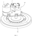
FIG. 1 is a structural schematic view of an embodiment of a cleaning apparatus of the present invention; -
FIG. 2 is a structural schematic view ofFIG. 1 where a part of the structure is omitted; -
FIG. 3 is an exploded schematic view ofFIG. 2 ; -
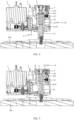
FIG. 4 is a cross-sectional view of an use state of the structure ofFIG. 2 (i.e., a schematic view of the structure after the rotating shaft is rotated in a first rotation direction); -
FIG. 5 is a cross-sectional view of another use state of the structure ofFIG. 2 (i.e., a schematic view of the structure after the rotating shaft is rotated in a second rotation direction); -
FIG. 6 is a structural schematic view of an use state of the structure ofFIG. 2 (i.e., a schematic view of the structure after the rotating shaft is rotated in a first rotation direction), where a part of the structure is omitted; -
FIG. 7 is an enlarged schematic view ofFIG. 6 , where a part of the structure is omitted; -
FIG. 8 is a structural schematic view of another use state of the structure ofFIG. 2 (i.e., a schematic view of the structure after the rotating shaft is rotated in a second rotation direction), where a part of the structure is omitted; -
FIG. 9 is a schematic view of an use state of a switch; and -
FIG. 10 is a schematic view of another use state of a switch. - In the drawings, the reference signs are listed:
100-lifting device; 1-drive motor; 2-rotating shaft; 21-mounting portion; 22-lifting drive portion; 221-limiting structure; 222-mounting groove; 23-thread; 231-groove; 232-screw thread; 24-triggering portion; 25-first gear; 3-transmission assembly; 31-second gear; 4-traction member; 41-traction slider; 42-mounting housing; 421-guide groove; 5-switch; 51-button; 6-first elastic member; 7-second elastic member; 200-machine body; 300-cleaning component. - The realization of the object, functional features and advantages of the present application will be further described in conjunction with embodiments with reference to the accompanying drawings.
- The following is a clear and complete description of the technical solution in the embodiment of the present application in combination with the drawings attached to the embodiment of the present application. Obviously, the described embodiment is only a part of the embodiment of the present application, but not the all embodiments. Based on the embodiments of the present application, all other embodiments obtained by those skilled in the art without creative labor are within the scope of protection of the present application.
- It should be noted that in case that the embodiments of the present application involve directional indications (such as up, down, left, right, front, rear...), , then the directional indication is only used to explain the relative position relationship and motion among components in a specific attitude (as shown in the attached figure). In case that the specific attitude changes, the directional indication will change accordingly.
- In addition, in case that an embodiment of the present application contains a description referring to "first", "second", etc., the description of "first", "second", etc., shall be used only for the purpose of description and shall not be understood to indicate or imply its relative importance or to indicate implicitly the quantity of the indicated technical features. Thus, a feature defined as "first" or "second" may explicitly or implicitly include at least one of the features. In addition, the technical solutions between embodiments may be combined with each other, but they must be based on the realization of those skilled in the art. When the combination of technical solutions is contradictory or impossible to be realized, it shall be considered that such combination of technical solutions does not exist and is not within the scope of protection required by the present application.
- The present application provides a cleaning apparatus. In some embodiments, the cleaning apparatus is a sweeping robot, a floor mopping robot, a sweeping and mopping robot or a window cleaning robot, etc., which is not limited herein.
- As shown in
FIGS. 1 and2 , in the embodiment, the cleaning apparatus includes amachine body 200, alifting device 100 and acleaning component 300. When the cleaning apparatus is a sweeping robot, thecleaning component 300 is a floor brush suitable for the sweeping robot; when the cleaning apparatus is a mopping robot, thecleaning component 300 is a mop suitable for the mopping robot, and when the cleaning apparatus is a window cleaning robot, the cleaning component 300is a cloth or paper cleaning supplies suitable for the window cleaning robot. - The
lifting device 100 is mounted on one side of themachine body 200, and thecleaning component 300 is mounted on the mountingportion 21 of thelifting device 100. Thelifting device 100 is used to drive thecleaning component 300 to do the lifting movement. It should be noted that when the cleaning apparatus is the sweeping robot or the mopping robot, thelifting device 100 is generally mounted at the bottom of themachine body 200 to drive thecleaning component 300 to move in the height direction of themachine body 200. When the cleaning apparatus is the window cleaning robot, thelifting device 100 is mounted in a front side of themachine body 200 to drive thecleaning component 300 to move in the front and back direction of themachine body 200. When the cleaning apparatus cleans some objects (such as but not limited to beds, sofas, etc.) which are set on the ground at intervals and need to be cleaned at the bottom surface, thelifting device 100 can also be arranged on the top of themachine body 200, which is not limited herein. - In some usage scenarios, when the
machine body 200 detects that objects such as carpets and other items are placed in a moving path of themachine body 200 that may interfere with the movement of thecleaning component 300, in order to prevent stains carried by cleaningcomponent 300 from contaminating these objects and ensure the smooth movement ofmachine body 200, thelifting device 100 can drive thecleaning component 300 to move in the direction adjacent to themachine body 200, so that thecleaning component 300 is separated from these objects. - In other usage scenarios, when the cleaning device completes the cleaning task, the
lifting device 100 drives thecleaning device 300 to move closer to themachine body 200 to keep thecleaning device 300 away from the ground in order to prevent the stain on thecleaning device 300 from contaminating the cleaned ground. - The cleaning apparatus with the lifting function of the
cleaning component 300 on the market needs to be provided with at least two drivers, one driver is used to drive thecleaning component 300 to rotate for cleaning, and the other one is used to drive the cleaning component to finish the lifting movement, the volume of the cleaning apparatus is increased due to the installation of two drivers, which is not conducive to the cleaning apparatus into a small space for cleaning operation, and the use of two drivers will lead to high manufacturing costs of cleaning apparatus, which is not conducive to improving the competitiveness of cleaning apparatus among similar products. - In order to solve the above problems, the present application provides a
lifting device 100. - In embodiments of the present application, as shown in
FIG. 2 to FIG. 10 , thelifting device 100 includes: adrive motor 1, arotating shaft 2, atransmission assembly 3 and atraction member 4. In particular, in some embodiments, thelifting device 100 further includes a housing, and the housing is used as a carrier for thedrive motor 1, therotating shaft 2, thetransmission assembly 3, thetraction member 4 and theswitch 5 mentioned below. The housing can be mounted on themachine body 200, the structural shape of the housing can be adjusted according to the actual use requirements, which is not limited herein. In other embodiments, thedrive motor 1, therotating shaft 2, thetransmission assembly 3, thetraction assembly 4, and theswitch 5 mentioned below are mounted directly on themachine body 200, which is not limited herein. - As shown in
FIGS. 3 ,6 and8 , therotating shaft 2 includes a mountingportion 21 and a liftingdrive portion 22 that are connected with each other, and the mountingportion 21 is used to be connected with thecleaning component 300. In particular, in order to facilitate the maintenance and replacement of thecleaning component 300, the mountingportion 21 is detachably connected to thecleaning component 300. During the specific implementation, in some embodiments, as can be seen inFIG. 4 , an insertion slot (not identified inFIG. 4 ) is arranged on thecleaning component 300, and the end of mountingportion 21 is detachably inserted into the insertion slot. In other embodiments, a first magnetic suction member is provided on one of the mountingportion 21 and thecleaning component 300, and a second magnetic suction member magnetically matched with the first magnetic suction member is provided on the other one of the mountingportion 21 and thecleaning component 300. The mountingportion 21 is assembled with thecleaning component 300 through a magnetic connection between the first magnetic suction member and the second magnetic suction member. In yet embodiment, a mechanical claw is arranged at an end of the mountingportion 21 for grabbing thecleaning component 300, so as to grab thecleaning component 300 and drive thecleaning component 300 to move for cleaning. The structure of assembling between the mountingportion 21 and thecleaning component 300 is various, which is not limited herein. - The
transmission assembly 3 is respectively connected with the output end of thedrive motor 1 and therotating shaft 2 to transfer the power of thedrive motor 1 to therotating shaft 2. In the specific implementation, thetransmission assembly 3 is a gear, a rack or a belt and other parts for realizing transmission between the output end of thedrive motor 1 and therotating shaft 2. The transmission structure is various, it is not enumerated here, the components that can transfer the rotation of thedrive motor 1 to therotating shaft 2 to rotate therotation shaft 2 are satisfied, which is not limited herein. - The
traction member 4 is threaded to the liftingdrive portion 22. - In the specific implementation, in some embodiments, the peripheral wall of the lifting
drive portion 22 is provided with an external thread extending spirally along its own axis direction (the external thread can bethread 23 as shown inFIG. 7 ), thetraction member 4 includes a cylinder (not shown) sleeved on the liftingdrive portion 22, and the inner peripheral wall of the cylinder is provided with an internal thread matching with the external thread. The cylinder is threaded to the liftingdrive portion 22 through the match between the internal thread and the external thread. - In other embodiments, a threaded hole (not shown) is provided at one end of the lifting
drive portion 22 away from the mountingportion 21, and thetraction member 4 includes a threaded post matching with the threaded hole (not shown), the threaded post is threaded to the threaded hole. - In yet embodiment, as shown in
FIG. 7 , the peripheral wall of the liftingdrive portion 22 is provided withthread 23 extending spirally along its own axis direction, and thetraction member 4 includes atraction slider 41 arranged on one side of the liftingdrive portion 22, and at a part of the structure of thetraction slider 41 is slideably arranged in thegroove 231 ofthread 23. It can be understood that using the method that thetraction slider 41 being matched with thethread 23 can simplify the structure of thetraction member 4 when comparing with the above two embodiments, such method reduces the material cost of thetraction member 4, while conducive to reduce the volume of thelifting device 100, which is conducive to the cleaning apparatus into the narrow space for cleaning operation. - When the
rotating shaft 2 is driven by thedrive motor 1 along the first rotation direction, the liftingdrive portion 22 rotates relative to thetraction member 4, and therotating shaft 2 moves in a direction that approaches the surface to be cleaned, such as the ground, glass surface, etc; When therotating shaft 2 is driven by thedrive motor 1 along the second rotation direction opposite to the first rotation direction, the liftingdrive portion 22 rotates relative to thetraction member 4 and therotating shaft 2 moves along the direction away from the surface to be cleaned. - Take the
lifting device 100 mounted at the bottom ofmachine body 200 as an example, as shown inFIG. 3 ,FIG. 4 and FIG. 5 , thetraction member 4 does not move, when therotating shaft 2 rotates along the first rotation direction, that is, when therotating shaft 2 rotates counterclockwise around its own axis shown inFIG. 3 , therotating shaft 2 does down under the reaction force oftraction member 4. In the embodiment where thetraction member 4 includes a cylinder or a threaded post, when therotating shaft 2 is went down to thecleaning component 300 being in contact with the ground, therotating shaft 2 can be locked with the cylinder or threaded post in a threaded method, and when thecleaning component 300 is rotated to mop the ground, therotating shaft 2 can be rotated with the cylinder or threaded post. In the embodiment where thetraction member 4 includes atraction slider 41, when therotating shaft 2 is went down to thecleaning component 300 being in contact with the ground and continuously rotating, thetraction slider 41 can move back and forth on the last two turns of thescrew thread 232 of thethread 23. - When the
rotating shaft 2 rotates in the second direction of rotation, that is, when rotatingshaft 2 rotates clockwise about its own axis shown inFIG. 3 , therotating shaft 2 goes up under the reaction force oftraction member 4. In the above embodiment where thetraction member 4 includes a cylinder or a threaded post, when therotating shaft 2 goes up to thecleaning component 300 being in contact with the ground, at this time, thedrive motor 1 can be stopped to prevent the cylinder or thread post from disconnecting with therotating shaft 2. Similarly, in the above embodiment wheretraction member 4 includes thetraction slider 41, thedrive motor 1 can also be stopped when therotating shaft 2 is went up to thecleaning component 300 being in contact with the ground to prevent thetraction slider 41 from slipping out of the end ofthread 23 adjacent to the mountingportion 21. - It can be understood that in the
lifting device 100 of the present application, thetraction member 4 is arranged to be threaded to therotating shaft 2, so that when therotating shaft 2 rotates along different rotation directions, theunmovable traction member 4 can exert a reaction force to therotating shaft 2 through the screw thread at the thread connection to drive therotating shaft 2 to go up or go down. When thetraction member 4 goes down to a height that thecleaning component 300 can perform cleaning, thetraction member 4 can be locked with the rotating shaft in a threaded manner, or thetraction member 4 moves back and forth on the last two circles of the screw thread on therotating shaft 2, so as to facilitate therotating shaft 2 continuous rotation to drive thecleaning component 300 rotating cleaning. Therefore, the design of the present application can realize the rotating cleaning of thecleaning component 300 only by a drive motor to drive thecleaning component 300, and the lifting technical effect of thecleaning component 300 is also realized, which is conducive to reduce the volume of thelifting device 100, and to reduce the volume of cleaning apparatus using thelifting device 100, the reducing the volume of cleaning apparatus is conducive to the cleaning of narrow space and reduce the manufacturing cost of cleaning apparatus. - In order to reduce the friction between the
traction slider 41 and a groove wall of thegroove 231 and improve the smoothness of sliding of thetraction slider 41 in thegroove 231, in some embodiments, the part of thetraction slider 41 located in thegroove 231 ofthread 23 is arranged in a cylindrical shape. - Based on the above embodiment where the
traction member 4 includes thetraction slider 41, an end ofgroove 231 ofthread 23 adjacent to the mountingportion 21 is further provided with a limitingstructure 221, and the limitingstructure 221 is used to limit thetraction slider 41 from sliding out of thegroove 231 of thethread 23. When therotating shaft 2 rotates along the second rotation direction, thetraction slider 41 and the limitingstructure 221 will approach each other as the liftingdrive portion 22 moves away from the mountingportion 21, until thetraction slider 41 is abutted against the limitingstructure 221. When thetraction slider 41 abuts against the limitingstructure 221, thecleaning component 300 is moved to a position separated from the ground. After that, in some embodiments, therotating shaft 2 can be stopped to rotate by stopping thedrive motor 1 to save energy. In other embodiments, thedrive motor 1 can not be stopped, and thetraction slider 41 is movably mounted on the housing, so that thetraction slider 41 can rotate withrotating shaft 2 under the push of the limitingstructure 221. It can be understood that the movement oftraction slider 41 is restricted by the limitingstructure 221, which can effectively prevent the interruption of the fit between thetraction slider 41 and thethread 23, and it is conducive to ensuring the reliability of product operation. - In the specific implementation, the limiting
structure 221 is a limiting wall, a limiting convex edge or a limiting bump, and other structures arranged ingroove 231, and which is not limited herein. - In some embodiments, the
lifting device 100 further includes aswitch 5, theswitch 5 is electrically connected to thedrive motor 1, and theswitch 5 stops thedrive motor 1 when triggered. The trigger position of theswitch 5 is arranged on the moving path of therotating shaft 2. When liftingdrive portion 22 moves away from mountingportion 21, therotating shaft 2 can trigger theswitch 5. In the embodiment, when therotating shaft 2 rotates along the second rotation direction, therotating shaft 2 will drive thecleaning component 300 away from the surface to be cleaned (such as the ground, glass surface, etc.), when thecleaning component 300 moves to a certain height from the surface to be cleaned, theswitch 5 can be triggered by therotating shaft 2, and then stop thedrive motor 1 to save energy. - In the embodiment where a limiting
structure 221 is provided in thegroove 231 of thethread 23, as well as thelifting device 100 includes theswitch 5, theswitch 5 can be triggered before thetraction slider 41 abuts against the limitingstructure 221, when thetraction slider 41 is just abutted against the limitingstructure 221. - In the specific implementation, in some embodiments, the
switch 5 can becontact switch 5, such as but not limited to amicro switch 5, etc., therotating shaft 2 includes a triggering portion 24 protruding from the peripheral wall of the liftingdrive portion 22, the triggering portion 24 andthread 23 are spaced from each other; theswitch 5 is provided with abutton 51, thebutton 51 is arranged on the side of the triggering portion 24 facing away from the mountingportion 21. When the liftingdrive portion 22 moves away from mountingportion 21, the triggering portion 24 can press thebutton 51. It can be understood that the the mechanical method to trigger theswitch 5 has the advantages of easy implementation and simple control logic. In other embodiments, theswitch 5 can also be aninduction switch 5, such as but not limited to aninfrared induction switch 5, etc., which is not limited herein. - As shown in
FIGS. 9 and10 , the triggering portion 24 is a first gear 25 sleeved on the peripheral wall of the liftingdrive portion 22; thetransmission assembly 3 includes asecond gear 31 extending in parallel with therotating shaft 2, thesecond gear 31 is connected to thedrive motor 1 in a transmission manner, and thesecond gear 31 is meshed with the first gear 25. It can be understood that the gear meshing transmission manner has the advantages of simple implementation and high transmission reliability. At the same time, the first gear 25 round dual-purpose, that is, the first gear 25 on the one hand is used for meshing transmission with thetransmission assembly 3, on the other hand, the first gear 25 is used to trigger theswitch 5 with the movement of the liftingdrive portion 22, which is conducive to simplifying the structure of therotating shaft 2 and facilitate the miniaturization of product design. - It is worth noting that, in addition to stopping the
drive motor 1 with theswitch 5, in some embodiment, a Hall element is arranged at the output end ofdrive motor 1 to calculate the number of turns ofrotating shaft 2 along the second rotation direction, so as to timely stop thedrive motor 1 with a preset procedure when the traction pulley is about to separate away from thethread 23. - The
lifting device 100 includes a firstelastic member 6, the firstelastic member 6 is arranged on one side of the liftingdrive portion 22 facing away from the mountingportion 21 and connected with the liftingdrive portion 22 to provide a drive force to the liftingdrive portion 22 when the liftingdrive portion 22 moves in the direction that therotating shaft 2 approaches the surface to be cleaned. In the specific implementation, the firstelastic member 6 can be a spring, a rubber band and other elastic members. It can be understood that, the mountingportion 21 can be quickly adjacent to the surface to be cleaned under the driving of the firstelastic member 6, which is conducive to shorten the time spent for thecleaning component 300 to go down to the surface to be cleaned. - During the mounting of the first
elastic member 6, in some embodiments, an end of the liftingdrive portion 22 away from the mountingportion 21 is concavely provided with a mountinggroove 222, at least a part of the structure of the firstelastic member 6 is arranged in the mountinggroove 222, and an end of the firstelastic member 6 is elastically abutted against the bottom wall of the mountinggroove 222. In particular, the end of firstelastic member 6 facing away from the bottom wall of the mountinggroove 222 is connected to the housing, or is connected to themachine body 200, which is not limited herein. It can be understood that the cavity in the mountinggroove 222 can play a certain constraint role in the expansion and deformation of the firstelastic member 6, that is, the firstelastic member 6 can only deform in a depth direction of the mountinggroove 222 under the constraint of the mountinggroove 222, which is conducive to ensuring the reliability of the firstelastic member 6. In other embodiments, the end of the liftingdrive portion 22 is not provided with the mountinggroove 222, and the end of the firstelastic member 6 is directly fixed on the end of the liftingdrive portion 22, which is not limited herein. - Since the surface to be cleaned will inevitably have a bumpy situation, when the
cleaning component 300 moves from the low-lying place to a flat or steep place, or from the flat or steep place move to the low-lying place, thecleaning component 300 will inevitably shake, and then therotating shaft 2 and thetraction slider 41 are shaken in the housing, so that therotating shaft 2 and thetraction slider 41 are easy to rigid bump with other components (such as the inner wall of the housing). In order to reduce the adverse influence brought by shaking, in some embodiments, thelifting device 100 includes a secondelastic member 7, the secondelastic member 7 is arranged on a side of thetraction member 4 facing away from the mountingportion 21 and is connected with thetraction member 4, so that thetraction member 4 can be moved in the axis direction ofrotating shaft 2. Therefore, when thecleaning component 300 is shaking, the movement amplitude of therotating shaft 2 in a direction away from the surface to be cleaned can be effectively reduced under the elastic buffering of the firstelastic member 6. Similarly, the movement amplitude of the thetraction slider 41 in a direction away from the surface to be cleaned can be effectively reduced under the elastic buffering of the secondelastic member 7. Therefore, the bumping between therotating shaft 2, thetraction slider 41 and other components, and the noise caused by thelifting device 100 in the process of shaking is reduced. - Since the
traction slider 41 will limit the movement of therotating shaft 2 away from the direction of the surface to be cleaned, in case that when the shaking strength has been able to promote the compression deformation of the firstelastic member 6, but can not promote the compression deformation of the secondelastic member 7, at this time, therotating shaft 2 is unable to move under the restriction of thetraction slider 41, thus causing thecleaning component 300 can not pass through the surface to be cleaned with a larger slope. In order to avoid the above situation, in the embodiment, the elastic coefficient of the firstelastic member 6 is greater than or equal to that of the secondelastic member 7. In other embodiments, the elastic coefficient of the firstelastic element 6 can also be greater than that of the secondelastic element 7, which is not limited herein. - In order to ensure that the second
elastic member 7 can expand and deform in the moving direction of therotating shaft 2, in the embodiment, thetraction member 4 includes a mountinghousing 42 arranged on one side of the liftingdrive portion 22. The mountinghousing 42 is formed with aguide groove 421 extending in the same direction as the liftingdrive portion 22, and theguide groove 421 is provided with an opening arranged on a side of the mountinghousing 42 facing the liftingdrive portion 22, thetraction slider 41 is slidably mounted in theguide groove 421, and at least a part of the structure of thetraction slider 41 is inserted into thegroove 231 of thethread 23 through the opening, and at least a part of the structure of the secondelastic member 7 is arranged in theguide groove 421 and is connected with thetraction slider 41. - The present application further provides a cleaning system, which includes the cleaning apparatus, and the specific structure of the cleaning apparatus can be referred to the above embodiments. Since the cleaning system adopts all the technical solutions of the above embodiments, the cleaning system at least has all the beneficial effects brought by the technical solutions of the above embodiments, which will not be repeated herein.
- In the embodiment, the cleaning system can include a service station used in conjunction with the cleaning apparatus, the cleaning apparatus can be parked to the service station, and the service station provides e one or more of charging, cleaning and other services.
Claims (14)
- A lifting device (100), applied to a cleaning apparatus and configured to drive a cleaning component (300) of the cleaning apparatus to do lifting movement, wherein the lifting device (100) comprises:a drive motor (1);a rotating shaft (2), comprising a mounting portion (21) and a lifting drive portion (22) connected to the mounting portion, and the mounting portion being configured for connecting with the cleaning component (300), the cleaning component (300) is configured to clean a surface to be cleaned;a transmission assembly (3), respectively connected to an output end of the drive motor (1) and the rotating shaft (2), to transfer a power of the drive motor (1) to the rotating shaft (2); characterized in that the lifting device (100) comprises:a traction member (4), threaded to the lifting drive portion (22);wherein when the rotating shaft (2) is rotated in a first rotation direction driven by the drive motor (1), the lifting drive portion (22) rotates relative to the traction member (4) and the rotating shaft (2) moves in a direction that approaches the surface to be cleaned; andwhen the rotating shaft (2) is rotated in a second rotation direction opposite to the first rotation direction driven by the drive motor (1), the lifting drive portion (22) rotates relative to the traction member (4) and the rotating shaft (2) moves in a direction away from the surface to be cleaned.
- The lifting device (100) according to claim 1, wherein a peripheral wall of the lifting drive portion (22) is provided with a thread (23) spirally extending along an axis direction of the lifting drive portion (22), the traction member (4) comprises a traction slider (41) arranged on a side of the lifting drive portion (22), and at least a part of a structure of the traction slider (41) is slidably arranged in a groove (231) of the thread (23).
- The lifting device (100) according to claim 2, wherein an end of the groove (231) of the thread (23) adjacent to the mounting portion (21) is provided with a limiting structure (221) configured for limiting the traction slider (41) from sliding out of the groove (231) of the thread (23).
- The lifting device (100) according to claim 2, wherein the lifting device (100) further comprises a switch (5) electrically connected with the drive motor (1), and the switch (5) is configured to be triggered to stop the drive motor (1); and
a triggering position (24) of the switch (5) is arranged on a moving path of the rotating shaft (2), and the rotating shaft (2) is able to trigger the switch (5) when the lifting drive portion (22) moves in the direction away from the surface to be cleaned. - The lifting device (100) according to claim 2, wherein a portion of the traction slider (41) located in the groove (231) of the thread (23) is arranged in a cylindrical shape.
- The lifting device (100) according to any one of claims 1 to 5, wherein the rotating shaft (2) comprises a triggering portion (24) projecting from the peripheral wall of the lifting drive portion (22), and the triggering portion (24) and the thread (23) are spaced away from each other; and
the lifting device (100) further comprises a switch (5) electrically connected with the drive motor (1), the switch (5) is a contact switch, the switch (5) is provided with a button (51), the button (51) is arranged on a side of the triggering portion (24) facing away from the mounting portion (21), and triggering portion (24) presses the button (51) when the lifting drive portion (22) moves in a direction away from the mounting portion (21). - The lifting device (100) according to claim 6, wherein the triggering portion (24) is a first gear (25) sleeved on the peripheral wall of the lifting drive portion (24);
the transmission assembly (3) comprises a second gear (31) extending in parallel with the rotating shaft (2), and the second gear (31) is in a transmission connection with the drive motor (1), and the second gear (31) is meshed with the first gear (25). - The lifting device (100) according to claim 1, wherein the lifting device (100) further comprises a first elastic member (6), the first elastic member (6) is arranged at a side of the lifting drive portion (22) facing away from the mounting portion (21) and is connected to the lifting drive portion (22), so as to provide a drive force to the lifting drive portion (22) when the lifting drive portion (22) moves in a direction that approaches the surface to be cleaned.
- The lifting device (100) according to claim 8, wherein the lifting device (100) further comprises a second elastic member (7), the second elastic member (7) is arranged at a side of the traction member (4) facing away from the mounting portion (21) and is connected to the traction member (4), so as to enable the traction member (4) to be movable in an axis direction of the rotating shaft (2).
- The lifting device (100) according to claim 9, wherein a peripheral wall of the lifting drive portion (22) is provided with a thread (23) spirally extending along an axis direction of the lifting drive portion (22), the traction member (4) comprises a traction slider (41) arranged on a side of the lifting drive portion (22), and at least a part of a structure of the traction slider (41) is slidably arranged in a groove (231) of the thread (23); and
the traction member (4) comprises a mounting housing (42) arranged at a side of the lifting drive portion (22), the mounting housing (42) is provided with a guide groove (421) extending in a same extending direction of the lifting drive portion (22), the guide groove (421) is arranged to have an opening at a side of the mounting housing (42) facing the lifting drive portion (22), the traction slider (41) is slidably mounted at the guide groove (421), and a part of a structure of the traction slider (41) is inserted into the groove (231) of the thread (23) through the opening, and at least a part of a structure of the second elastic member (7) is arranged in the guide groove (421) and connected with the traction slider (41). - The lifting device (100) according to claim 9, wherein an elastic coefficient of the first elastic member (6) is greater than or equal to an elastic coefficient of the second elastic member (7).
- The lifting device (100) according to claim 8, wherein an end of the lifting drive portion (22) facing away from the mounting portion (21) is concavely provided with a mounting groove (222), at least a part of a structure of the first elastic member (6) is arranged in the mounting groove (222), and an end of the first elastic member (6) is elastically abutted against a bottom wall of the mounting groove (222).
- A cleaning apparatus, comprising:a machine body (200);the lifting device (100) according to any one of claims 1 to 12, the lifting device (100) being mounted at a side of the machine body (200); anda cleaning component (300), mounted on a mounting portion (21).
- A cleaning system, comprising a cleaning apparatus, wherein the cleaning apparatus comprises:a machine body (200);the lifting device (100) according to any one of claims 1 to 12, the lifting device (100) being mounted at a side of the machine body (200); anda cleaning component (300), mounted on a mounting portion (21).
Applications Claiming Priority (1)
| Application Number | Priority Date | Filing Date | Title |
|---|---|---|---|
| CN202211378109.XA CN117982045A (en) | 2022-11-04 | 2022-11-04 | Lifting devices and cleaning equipment |
Publications (3)
| Publication Number | Publication Date |
|---|---|
| EP4364627A2 EP4364627A2 (en) | 2024-05-08 |
| EP4364627A3 EP4364627A3 (en) | 2024-07-24 |
| EP4364627B1 true EP4364627B1 (en) | 2025-04-30 |
Family
ID=87570845
Family Applications (1)
| Application Number | Title | Priority Date | Filing Date |
|---|---|---|---|
| EP23191069.6A Active EP4364627B1 (en) | 2022-11-04 | 2023-08-11 | Lifting device and cleaning apparatus |
Country Status (5)
| Country | Link |
|---|---|
| US (1) | US20240148212A1 (en) |
| EP (1) | EP4364627B1 (en) |
| KR (1) | KR20250058039A (en) |
| CN (1) | CN117982045A (en) |
| WO (1) | WO2024093216A1 (en) |
Families Citing this family (5)
| Publication number | Priority date | Publication date | Assignee | Title |
|---|---|---|---|---|
| CN216317376U (en) * | 2021-09-29 | 2022-04-19 | 云鲸智能科技(东莞)有限公司 | Cleaning assembly lifting device and cleaning equipment |
| USD1093789S1 (en) * | 2023-06-25 | 2025-09-16 | Yunjing Intelligence Innovation (Shenzhen) Co., Ltd. | Cleaning robot |
| US20250000319A1 (en) * | 2023-06-28 | 2025-01-02 | Vorwerk & Co. Interholding Gmbh | Method of operating a floor cleaning device and floor cleaning device |
| WO2025242239A1 (en) * | 2024-05-20 | 2025-11-27 | 深圳市杉川机器人有限公司 | Cleaning robot |
| DE102024210040A1 (en) * | 2024-10-16 | 2026-04-16 | BSH Hausgeräte GmbH | System with a cleaning robot and a base station for regenerating the cleaning robot |
Family Cites Families (10)
| Publication number | Priority date | Publication date | Assignee | Title |
|---|---|---|---|---|
| US6065182A (en) * | 1996-06-07 | 2000-05-23 | Royal Appliance Mfg. Co. | Cordless wet mop and vacuum assembly |
| KR102308775B1 (en) * | 2019-07-31 | 2021-10-01 | 엘지전자 주식회사 | Cleaner |
| US11969125B2 (en) * | 2019-07-31 | 2024-04-30 | Lg Electronics Inc. | Mobile robot |
| KR102701527B1 (en) * | 2021-02-10 | 2024-09-04 | 윈징 인텔리전스 이노베이션 (쉔젠) 컴퍼니 리미티드 | Cleaning assembly and cleaning robot |
| CN215329596U (en) * | 2021-04-09 | 2021-12-28 | 美智纵横科技有限责任公司 | Cleaning device |
| CN113749574B (en) * | 2021-10-15 | 2025-08-12 | 普联技术有限公司 | Lifting device and cleaning robot |
| CN114010117B (en) * | 2021-11-01 | 2022-10-28 | 深圳市魅电科技有限公司 | Liftable formula robot of sweeping floor mops brush |
| CN114831546B (en) * | 2022-05-24 | 2025-12-30 | 普联技术有限公司 | Cleaning robots and cleaning equipment |
| CN217645157U (en) * | 2022-05-31 | 2022-10-25 | 佛山市银星智能制造有限公司 | Lifting and rotating device and cleaning robot |
| WO2024011479A1 (en) * | 2022-07-14 | 2024-01-18 | Sharkninja Operating Llc | Robotic cleaner |
-
2022
- 2022-11-04 CN CN202211378109.XA patent/CN117982045A/en active Pending
-
2023
- 2023-05-29 WO PCT/CN2023/096943 patent/WO2024093216A1/en not_active Ceased
- 2023-05-29 KR KR1020257010579A patent/KR20250058039A/en active Pending
- 2023-07-28 US US18/227,724 patent/US20240148212A1/en active Pending
- 2023-08-11 EP EP23191069.6A patent/EP4364627B1/en active Active
Also Published As
| Publication number | Publication date |
|---|---|
| EP4364627A3 (en) | 2024-07-24 |
| EP4364627A2 (en) | 2024-05-08 |
| WO2024093216A1 (en) | 2024-05-10 |
| CN117982045A (en) | 2024-05-07 |
| US20240148212A1 (en) | 2024-05-09 |
| KR20250058039A (en) | 2025-04-29 |
Similar Documents
| Publication | Publication Date | Title |
|---|---|---|
| EP4364627A2 (en) | Lifting device and cleaning apparatus | |
| US11837747B2 (en) | Battery case unlocking apparatus, battery case, and quick battery case replacement system | |
| CN111182275B (en) | Monitoring probe capable of being automatically cleaned | |
| WO2023241628A2 (en) | Cleaning device | |
| CN113786133A (en) | Automatic lifting mechanism, cleaning assembly and cleaning robot | |
| WO2023185222A1 (en) | Cleaning robot and control method for cleaning robot | |
| CN221153961U (en) | cleaning equipment | |
| CN222149934U (en) | Transmission assembly and cleaning device | |
| CN118680474A (en) | Cleaning device, cleaning equipment and cleaning system | |
| CN216569792U (en) | Automatic lifting mechanism, cleaning assembly and cleaning robot | |
| CN210828815U (en) | Opening and closing door assembly and dish washing machine using same | |
| EP4721638A1 (en) | Cleaning assembly for cleaning apparatus, and cleaning apparatus | |
| CN118749854A (en) | Gear mechanism, driving device, cleaning mechanism, cleaning equipment and cleaning base station | |
| CN114515127B (en) | Cleaning system and method for attaching and detaching cleaning unit of cleaning system | |
| CN115778252B (en) | Cleaning mechanism and cleaning robot | |
| WO2024037640A1 (en) | Cleaning equipment | |
| CN218168127U (en) | Glass wiper component | |
| CN218167870U (en) | Glass wiper and glass wiper assembly | |
| CN214157026U (en) | Liquid heating container | |
| CN220175025U (en) | Cleaning robot | |
| CN221475236U (en) | Robot removes buffer stop | |
| CN220045785U (en) | Floor sweeping machine and floor sweeping machine system | |
| CN215191287U (en) | Battery compartment and electric mop thereof | |
| CN222288030U (en) | Cleaning device | |
| CN222622882U (en) | Driving device, cleaning equipment and cleaning system |
Legal Events
| Date | Code | Title | Description |
|---|---|---|---|
| PUAI | Public reference made under article 153(3) epc to a published international application that has entered the european phase |
Free format text: ORIGINAL CODE: 0009012 |
|
| STAA | Information on the status of an ep patent application or granted ep patent |
Free format text: STATUS: REQUEST FOR EXAMINATION WAS MADE |
|
| 17P | Request for examination filed |
Effective date: 20230811 |
|
| AK | Designated contracting states |
Kind code of ref document: A2 Designated state(s): AL AT BE BG CH CY CZ DE DK EE ES FI FR GB GR HR HU IE IS IT LI LT LU LV MC ME MK MT NL NO PL PT RO RS SE SI SK SM TR |
|
| PUAL | Search report despatched |
Free format text: ORIGINAL CODE: 0009013 |
|
| AK | Designated contracting states |
Kind code of ref document: A3 Designated state(s): AL AT BE BG CH CY CZ DE DK EE ES FI FR GB GR HR HU IE IS IT LI LT LU LV MC ME MK MT NL NO PL PT RO RS SE SI SK SM TR |
|
| RIC1 | Information provided on ipc code assigned before grant |
Ipc: A47L 11/293 20060101ALI20240618BHEP Ipc: A47L 11/40 20060101ALI20240618BHEP Ipc: A47L 11/283 20060101AFI20240618BHEP |
|
| GRAP | Despatch of communication of intention to grant a patent |
Free format text: ORIGINAL CODE: EPIDOSNIGR1 |
|
| STAA | Information on the status of an ep patent application or granted ep patent |
Free format text: STATUS: GRANT OF PATENT IS INTENDED |
|
| INTG | Intention to grant announced |
Effective date: 20241212 |
|
| GRAS | Grant fee paid |
Free format text: ORIGINAL CODE: EPIDOSNIGR3 |
|
| GRAA | (expected) grant |
Free format text: ORIGINAL CODE: 0009210 |
|
| STAA | Information on the status of an ep patent application or granted ep patent |
Free format text: STATUS: THE PATENT HAS BEEN GRANTED |
|
| AK | Designated contracting states |
Kind code of ref document: B1 Designated state(s): AL AT BE BG CH CY CZ DE DK EE ES FI FR GB GR HR HU IE IS IT LI LT LU LV MC ME MK MT NL NO PL PT RO RS SE SI SK SM TR |
|
| REG | Reference to a national code |
Ref country code: CH Ref legal event code: EP Ref country code: GB Ref legal event code: FG4D |
|
| REG | Reference to a national code |
Ref country code: IE Ref legal event code: FG4D |
|
| REG | Reference to a national code |
Ref country code: DE Ref legal event code: R096 Ref document number: 602023003171 Country of ref document: DE |
|
| P01 | Opt-out of the competence of the unified patent court (upc) registered |
Free format text: CASE NUMBER: APP_27824/2025 Effective date: 20250611 |
|
| REG | Reference to a national code |
Ref country code: NL Ref legal event code: MP Effective date: 20250430 |
|
| REG | Reference to a national code |
Ref country code: AT Ref legal event code: MK05 Ref document number: 1789236 Country of ref document: AT Kind code of ref document: T Effective date: 20250430 |
|
| PG25 | Lapsed in a contracting state [announced via postgrant information from national office to epo] |
Ref country code: FI Free format text: LAPSE BECAUSE OF FAILURE TO SUBMIT A TRANSLATION OF THE DESCRIPTION OR TO PAY THE FEE WITHIN THE PRESCRIBED TIME-LIMIT Effective date: 20250430 Ref country code: PT Free format text: LAPSE BECAUSE OF FAILURE TO SUBMIT A TRANSLATION OF THE DESCRIPTION OR TO PAY THE FEE WITHIN THE PRESCRIBED TIME-LIMIT Effective date: 20250901 Ref country code: ES Free format text: LAPSE BECAUSE OF FAILURE TO SUBMIT A TRANSLATION OF THE DESCRIPTION OR TO PAY THE FEE WITHIN THE PRESCRIBED TIME-LIMIT Effective date: 20250430 |
|
| PGFP | Annual fee paid to national office [announced via postgrant information from national office to epo] |
Ref country code: DE Payment date: 20250812 Year of fee payment: 3 |
|
| REG | Reference to a national code |
Ref country code: LT Ref legal event code: MG9D |
|
| PG25 | Lapsed in a contracting state [announced via postgrant information from national office to epo] |
Ref country code: NO Free format text: LAPSE BECAUSE OF FAILURE TO SUBMIT A TRANSLATION OF THE DESCRIPTION OR TO PAY THE FEE WITHIN THE PRESCRIBED TIME-LIMIT Effective date: 20250730 Ref country code: GR Free format text: LAPSE BECAUSE OF FAILURE TO SUBMIT A TRANSLATION OF THE DESCRIPTION OR TO PAY THE FEE WITHIN THE PRESCRIBED TIME-LIMIT Effective date: 20250731 |
|
| PG25 | Lapsed in a contracting state [announced via postgrant information from national office to epo] |
Ref country code: PL Free format text: LAPSE BECAUSE OF FAILURE TO SUBMIT A TRANSLATION OF THE DESCRIPTION OR TO PAY THE FEE WITHIN THE PRESCRIBED TIME-LIMIT Effective date: 20250430 Ref country code: NL Free format text: LAPSE BECAUSE OF FAILURE TO SUBMIT A TRANSLATION OF THE DESCRIPTION OR TO PAY THE FEE WITHIN THE PRESCRIBED TIME-LIMIT Effective date: 20250430 |
|
| PG25 | Lapsed in a contracting state [announced via postgrant information from national office to epo] |
Ref country code: BG Free format text: LAPSE BECAUSE OF FAILURE TO SUBMIT A TRANSLATION OF THE DESCRIPTION OR TO PAY THE FEE WITHIN THE PRESCRIBED TIME-LIMIT Effective date: 20250430 |
|
| PG25 | Lapsed in a contracting state [announced via postgrant information from national office to epo] |
Ref country code: HR Free format text: LAPSE BECAUSE OF FAILURE TO SUBMIT A TRANSLATION OF THE DESCRIPTION OR TO PAY THE FEE WITHIN THE PRESCRIBED TIME-LIMIT Effective date: 20250430 |
|
| PG25 | Lapsed in a contracting state [announced via postgrant information from national office to epo] |
Ref country code: AT Free format text: LAPSE BECAUSE OF FAILURE TO SUBMIT A TRANSLATION OF THE DESCRIPTION OR TO PAY THE FEE WITHIN THE PRESCRIBED TIME-LIMIT Effective date: 20250430 |
|
| PGFP | Annual fee paid to national office [announced via postgrant information from national office to epo] |
Ref country code: FR Payment date: 20250828 Year of fee payment: 3 |
|
| PG25 | Lapsed in a contracting state [announced via postgrant information from national office to epo] |
Ref country code: RS Free format text: LAPSE BECAUSE OF FAILURE TO SUBMIT A TRANSLATION OF THE DESCRIPTION OR TO PAY THE FEE WITHIN THE PRESCRIBED TIME-LIMIT Effective date: 20250731 |
|
| PG25 | Lapsed in a contracting state [announced via postgrant information from national office to epo] |
Ref country code: IS Free format text: LAPSE BECAUSE OF FAILURE TO SUBMIT A TRANSLATION OF THE DESCRIPTION OR TO PAY THE FEE WITHIN THE PRESCRIBED TIME-LIMIT Effective date: 20250830 |
|
| PG25 | Lapsed in a contracting state [announced via postgrant information from national office to epo] |
Ref country code: LV Free format text: LAPSE BECAUSE OF FAILURE TO SUBMIT A TRANSLATION OF THE DESCRIPTION OR TO PAY THE FEE WITHIN THE PRESCRIBED TIME-LIMIT Effective date: 20250430 |
|
| PG25 | Lapsed in a contracting state [announced via postgrant information from national office to epo] |
Ref country code: DK Free format text: LAPSE BECAUSE OF FAILURE TO SUBMIT A TRANSLATION OF THE DESCRIPTION OR TO PAY THE FEE WITHIN THE PRESCRIBED TIME-LIMIT Effective date: 20250430 Ref country code: SM Free format text: LAPSE BECAUSE OF FAILURE TO SUBMIT A TRANSLATION OF THE DESCRIPTION OR TO PAY THE FEE WITHIN THE PRESCRIBED TIME-LIMIT Effective date: 20250430 |
|
| PG25 | Lapsed in a contracting state [announced via postgrant information from national office to epo] |
Ref country code: CZ Free format text: LAPSE BECAUSE OF FAILURE TO SUBMIT A TRANSLATION OF THE DESCRIPTION OR TO PAY THE FEE WITHIN THE PRESCRIBED TIME-LIMIT Effective date: 20250430 |
|
| PG25 | Lapsed in a contracting state [announced via postgrant information from national office to epo] |
Ref country code: EE Free format text: LAPSE BECAUSE OF FAILURE TO SUBMIT A TRANSLATION OF THE DESCRIPTION OR TO PAY THE FEE WITHIN THE PRESCRIBED TIME-LIMIT Effective date: 20250430 |
|
| PG25 | Lapsed in a contracting state [announced via postgrant information from national office to epo] |
Ref country code: SK Free format text: LAPSE BECAUSE OF FAILURE TO SUBMIT A TRANSLATION OF THE DESCRIPTION OR TO PAY THE FEE WITHIN THE PRESCRIBED TIME-LIMIT Effective date: 20250430 |
|
| PG25 | Lapsed in a contracting state [announced via postgrant information from national office to epo] |
Ref country code: IT Free format text: LAPSE BECAUSE OF FAILURE TO SUBMIT A TRANSLATION OF THE DESCRIPTION OR TO PAY THE FEE WITHIN THE PRESCRIBED TIME-LIMIT Effective date: 20250430 |
|
| REG | Reference to a national code |
Ref country code: DE Ref legal event code: R097 Ref document number: 602023003171 Country of ref document: DE |
|
| PG25 | Lapsed in a contracting state [announced via postgrant information from national office to epo] |
Ref country code: RO Free format text: LAPSE BECAUSE OF FAILURE TO SUBMIT A TRANSLATION OF THE DESCRIPTION OR TO PAY THE FEE WITHIN THE PRESCRIBED TIME-LIMIT Effective date: 20250430 |
|
| PLBE | No opposition filed within time limit |
Free format text: ORIGINAL CODE: 0009261 |
|
| STAA | Information on the status of an ep patent application or granted ep patent |
Free format text: STATUS: NO OPPOSITION FILED WITHIN TIME LIMIT |
|
| REG | Reference to a national code |
Ref country code: CH Ref legal event code: L10 Free format text: ST27 STATUS EVENT CODE: U-0-0-L10-L00 (AS PROVIDED BY THE NATIONAL OFFICE) Effective date: 20260311 |
|
| PG25 | Lapsed in a contracting state [announced via postgrant information from national office to epo] |
Ref country code: MC Free format text: LAPSE BECAUSE OF FAILURE TO SUBMIT A TRANSLATION OF THE DESCRIPTION OR TO PAY THE FEE WITHIN THE PRESCRIBED TIME-LIMIT Effective date: 20250430 |
|
| 26N | No opposition filed |
Effective date: 20260202 |
|
| PG25 | Lapsed in a contracting state [announced via postgrant information from national office to epo] |
Ref country code: LU Free format text: LAPSE BECAUSE OF NON-PAYMENT OF DUE FEES Effective date: 20250811 |