EP4364550A1 - Seeder assembly, method for distributing product and tank - Google Patents
Seeder assembly, method for distributing product and tank Download PDFInfo
- Publication number
- EP4364550A1 EP4364550A1 EP23202052.9A EP23202052A EP4364550A1 EP 4364550 A1 EP4364550 A1 EP 4364550A1 EP 23202052 A EP23202052 A EP 23202052A EP 4364550 A1 EP4364550 A1 EP 4364550A1
- Authority
- EP
- European Patent Office
- Prior art keywords
- tank
- chamber
- product
- coupled
- controller
- Prior art date
- Legal status (The legal status is an assumption and is not a legal conclusion. Google has not performed a legal analysis and makes no representation as to the accuracy of the status listed.)
- Pending
Links
- 238000000034 method Methods 0.000 title claims abstract description 21
- 239000012530 fluid Substances 0.000 claims 1
- 239000000463 material Substances 0.000 description 117
- 239000000203 mixture Substances 0.000 description 21
- 230000000007 visual effect Effects 0.000 description 5
- 230000008878 coupling Effects 0.000 description 4
- 238000010168 coupling process Methods 0.000 description 4
- 238000005859 coupling reaction Methods 0.000 description 4
- 239000003337 fertilizer Substances 0.000 description 3
- 238000005192 partition Methods 0.000 description 3
- 208000026817 47,XYY syndrome Diseases 0.000 description 2
- 230000005484 gravity Effects 0.000 description 2
- 238000005303 weighing Methods 0.000 description 2
- 230000006978 adaptation Effects 0.000 description 1
- 239000012773 agricultural material Substances 0.000 description 1
- 239000000575 pesticide Substances 0.000 description 1
Images





Classifications
-
- A—HUMAN NECESSITIES
- A01—AGRICULTURE; FORESTRY; ANIMAL HUSBANDRY; HUNTING; TRAPPING; FISHING
- A01C—PLANTING; SOWING; FERTILISING
- A01C7/00—Sowing
- A01C7/08—Broadcast seeders; Seeders depositing seeds in rows
- A01C7/081—Seeders depositing seeds in rows using pneumatic means
-
- A—HUMAN NECESSITIES
- A01—AGRICULTURE; FORESTRY; ANIMAL HUSBANDRY; HUNTING; TRAPPING; FISHING
- A01C—PLANTING; SOWING; FERTILISING
- A01C15/00—Fertiliser distributors
- A01C15/003—Bulk fertiliser or grain handling in the field or on the farm
-
- A—HUMAN NECESSITIES
- A01—AGRICULTURE; FORESTRY; ANIMAL HUSBANDRY; HUNTING; TRAPPING; FISHING
- A01C—PLANTING; SOWING; FERTILISING
- A01C15/00—Fertiliser distributors
- A01C15/005—Undercarriages, tanks, hoppers, stirrers specially adapted for seeders or fertiliser distributors
- A01C15/006—Hoppers
-
- A—HUMAN NECESSITIES
- A01—AGRICULTURE; FORESTRY; ANIMAL HUSBANDRY; HUNTING; TRAPPING; FISHING
- A01C—PLANTING; SOWING; FERTILISING
- A01C15/00—Fertiliser distributors
- A01C15/04—Fertiliser distributors using blowers
-
- A—HUMAN NECESSITIES
- A01—AGRICULTURE; FORESTRY; ANIMAL HUSBANDRY; HUNTING; TRAPPING; FISHING
- A01C—PLANTING; SOWING; FERTILISING
- A01C7/00—Sowing
- A01C7/08—Broadcast seeders; Seeders depositing seeds in rows
Definitions
- the present disclosure relates generally to row seeders for an agricultural machine, and more specifically to a row seeder having an intermediate tank.
- Air seeders are frequently used as an agricultural machine to distribute seed and/or fertilizer. These machines often utilize one or more large volume tanks that feed a destination, which in some instances are third tanks, sometimes referred to as hoppers, that are located on row units.
- the third tanks often contain a small volume of seed and distributes the seed into the ground.
- Large volume tanks also known as a first tank, are difficult to locate on the chassis of a traditional air seeder because of its large size. Even if one or more first tanks are placed on an air seeder chassis, this will create difficulties when the air seeder is folded. Therefore, one or more large volume tanks are commonly towed with the air seeder.
- the one or more first tanks are referred to as a commodity cart. Therefore, it is desirable to have medium size tanks, sometimes known as intermediate tanks or second tanks, on the air seeder that receives material from the one or more first tanks, and where each second tank distributes the material to one or more third tanks.
- the seeder has a chassis with a first end and a second end; a row unit configured to couple to the chassis; a third tank configured to couple to the row unit; a second tank configured to couple to the third tank; and a first tank configured to couple to the second tank.
- the first tank is configured to distribute an air and material mixture to the second tank
- the second tank is configured to distribute the air and material mixture to the third tank
- the third tank is configured to distribute the air and material mixture to the row unit
- the row unit is configured to distribute the material into ground.
- the second tank further includes an inlet and an outlet, configured such that an air and material mixture enters the second tank through the inlet and exits the second tank through the outlet. It also includes a first chamber with a first level, a second chamber with a second level, and a screen with a first end and a second end, wherein the second end of the screen is coupled to the first chamber, and the first end of the screen is located above the second end.
- the screen partially partitions the first chamber from the second chamber, and the inlet is located at or above the height of the screen;
- the outlet is coupled to a connection with one inlet and more than one outlet, such that one outlet may provide a seed and material mixture to two or more third tanks.
- the seeder assembly may also include a meter coupled to the first tank, wherein the meter controls the flow of material that is distributed from the first tank. Additionally, the meter is coupled to a controller, such that the controller provides input to the meter.
- the seeder assembly further includes a first sensor coupled to the second tank at a first height and the first sensor is configured to detect whether the material collected in the first chamber has reached the height of the first sensor.
- the seeder assembly may also include a status indicator wherein the first sensor provides an input to the status indicator and the status indicator provides an output.
- the seeder assembly of this embodiment may additionally include a controller coupled to the first sensor and a status indicator in communication with the first controller. In this embodiment, the controller receives input from the first sensor and the controller provides input to the status indicator, and the status indicator receives input from the controller and provides an output.
- the seeder assembly may also include a second sensor coupled to the second tank at a second height, wherein the second sensor detects whether the material collected in the first chamber has reached the height of the second sensor, further wherein height of the first sensor is greater than the height of the second sensor.
- This seeder assembly may further include, a controller operatively coupled to the first sensor and the second sensor; and a status indicator operatively coupled to the controller. The controller receives input from the first and second sensors and the controller provides input to the status indicator and the status indicator provides an output.
- the seeder assembly may further include a load cell coupled to the second tank, wherein the load cell is configured to weigh a force upon it.
- the seeder assembly also includes a sensor coupled to the row unit, wherein the sensor counts the material that is distributed into the ground through the row unit.
- the seeder assembly further includes a distribution line, wherein the second tank and the third tank are coupled with the distribution line.
- a method for distributing seed includes: providing a seeder, a first tank, a second tank, a third tank, and a row unit; distributing an air and material mixture from the first tank to the second tank; distributing the air and material mixture from the second tank to the third tank; distributing the air and material mixture from the third tank to the air seeder; and distributing the material from the air seeder to an underlying ground.
- the method further includes: providing a second tank with an inlet, an outlet, a first chamber with a first level, a second chamber with a second level, and a screen that partially partitions the first chamber from the second chamber; distributing the air and material mixture into the first chamber of the second tank through the inlet, wherein the material collects in the first chamber while the air continues flowing through the first chamber, through the second chamber, and out of the second tank via the outlet; continuing to distribute the air and material mixture into the first chamber such that the material collects in the first chamber and the material reaches a height that is at or above the screen.
- It also includes selectively moving material to the second chamber of the second tank when material in the first chamber reaches a height greater than the height of the screen; moving material out of the second chamber via the outlet; moving material from the outlet to the third tank; distributing material from the third tank to the row unit; and distributing material from the row unit to the underlying ground.
- the method also includes: providing a first sensor coupled to the second tank, wherein the first sensor is located at a first height; and providing a status indicator that is in wireless communication with the first sensor; wherein the first sensor is configured to detect if the material collected in the first chamber has reached the first height.
- the status indicator may also receive input from the first sensor and the status indicator provides an output.
- the method of further includes a second sensor coupled to the second tank, wherein the second sensor is located at a second height and wherein the sensor is configured to detect if the material collected in the first chamber has reached the second height. Also, the second sensor is in wireless communication with the status indicator, and the status indicator receives input from the second sensor and the status indicator provides an output.
- Another embodiment may include a method of calibrating a meter. This method may include: providing a first tank and a second tank; distributing product from the first tank to the second tank by rotating the meter; collecting product in the second tank; determining via a first sensor when the product reaches a first threshold level and determining via a second sensor when the product reaches a second threshold level in the second tank; and determining a number of revolutions rotated by the meter between the product reaching the first threshold level and the second threshold level.
- the method may further comprise coupling a first sensor to the second tank at the first threshold level and a second sensor to the second tank at the second threshold level, wherein the second threshold level is greater than the first threshold level.
- Another embodiment may include the method of calibrating a meter, wherein the method further comprises coupling a load cell to the second tank; weighing the second tank via the load cell when the second tank is empty of any product; continuously transferring product into the second tank until the second sensor detects product at the second threshold level; and weighing the second tank via the load cell once the first sensor detects material at the first threshold level.
- this method may further comprise determining the number of revolutions of the meter via a third sensor.
- the method may also include a load cell and a first sensor coupled to the second tank, wherein the load cell weighs the second tank when the second tank is empty. Additionally, material is distributed into the second tank until the first sensor detects material, and the load cell measures the weight of the second tank after the first sensor detects material. In one example, the method may also include a third sensor, wherein the third sensor counts and provides an output of the number of revolutions made by the meter.
- the seeder assembly 2 may include a seeder 4, a tractor 6, and one or more first tanks 12, 14, 16, 18.
- the seeder 4 may have a chassis 28 with a first end 42 and a second end 44, a seeder wheel 30, a firming wheel 40, a row unit 48, a third tank 46, and a second tank 34.
- the first end 42 of the chassis 28 may be coupled to the tractor 6, and the second end 44 of the chassis 28 may be coupled to one or more first tanks 12, 14, 16, 18.
- the seeder 4 may be towed between the tractor 6 and the one or more first tanks 12, 14, 16, 18.
- the one or more first tanks 12, 14, 16, 18 may be towed between the tractor 6 and the seeder 4.
- the seeder 4 and the one or more first tanks 12, 14, 16, 18 may be combined to form a unified configuration, rather than a separate configuration. While certain configurations are provided, other configurations of the seeder assembly 2 is contemplated in this disclosure.
- the row unit 48 may be coupled to the first end 42 of the chassis 28.
- the row unit 48 may also be coupled to the third tank 46.
- the row unit 48 may be configured to receive an air and material mixture from the third tank 46 and distribute the material in the ground 50.
- the material may be seed.
- the material may be fertilizer or pesticide. While certain materials are disclosed herein, it should be understood that any type of agricultural material may be distributed with the seeder assembly 2.
- the third tank 46 may be coupled to the seeder chassis 28.
- the third tank 46 may also be coupled to the row unit 48.
- the third tank 46 and the row unit 48 may be coupled with a distribution line 36.
- the third tank 46 may be coupled to the top of the row unit 48, and the third tank 46 may distribute the air and material mixture into the row unit 48 without a distribution line 36.
- the third tank 46 may also be coupled to the second tank 34.
- the third tank 46 and the second tank 34 may be coupled via a distribution line 36.
- the third tank 46 may be configured to receive the air and material mixture from the second tank 34 and to distribute the air and material mixture to the row unit 48.
- the seeder chassis 28 may have a plurality of row units 48 coupled thereto.
- the row units 48 may distribute seed into an underlying ground 50. More specifically, the row unit 48 may selectively cut an opening or furrow into the ground 50 and distribute material into the opening or furrow. The firming wheel 40 may then cover the opening or furrow after the material has been distributed.
- the row unit 48 may have a sensor (not pictured) that counts the amount of material distributed from the row unit 48.
- the row unit 48 may be coupled to the first end 42 of the chassis 28. In other embodiments, the row unit 48 may be coupled to both or between the first end 42 and the second end 44 of the chassis 28. In still another embodiment, the row unit 48 may be coupled to the second end 44 of the chassis 28.
- the second tank 34 may be coupled to the chassis 28 of the seeder 4. In one embodiment the second tank 34 may be coupled to the chassis 28, such that the second tank 28 does not impede the seeder 4 when the seeder 4 is in a folded or transport position.
- the second tank 34 may be configured to distribute the air and material mixture to the third tank 46 via a distribution line 36.
- the second tank 34 may also be coupled to the one or more first tanks 12, 14, 16, 18 via a flow passage 32, such as a hose or distribution line.
- the second tank 34 may be configured to receive the air and material mixture from the one or more first tanks 12, 14, 16, 18.
- One or more first tanks 12, 14, 16, 18 may be coupled to the seeder 4.
- the one or more first tanks 12, 14, 16, 18, may be coupled to a commodity cart 8.
- the commodity cart 8 may comprise a chassis 10, one or more first tanks 12, 14, 16, 18, one or more wheels 20, a metering system 24, and a pneumatic distribution system 26.
- the one or more first tanks 12, 14, 16, 18 may be configured to receive material, contain material, and distribute material.
- the tanks 12, 14, 16, 18 may be a hopper, bin, box, or any other type of container.
- Each of the tanks 12, 14, 16, 18 may have a door 22 (a representative door is labelled). In one example, the door 22 may releasably seal an opening at an upper end 52 of the one or more first tanks 12, 14, 16, 18 for filling the one or more first tanks 12, 14, 16, 18 with material.
- the metering system 24 may include one or more meters (not pictured), louvers (not pictured), one or more motors (not pictured) a meter controller, and a sensor (not pictured).
- Each meter (not pictured) may include louvers that may be coupled to the motor and the louvers may be located within the housing. The louvers may turn via the motor within the housing. The louvers may move in a rotational direction within the housing.
- material may enter the housing, travel at least partially around the housing being directed by the louvers and the housing, and the material may exit the housing, being controllably distributed into the pneumatic distribution system 26.
- the metering system 24 may be configured to controllably move material from the tanks 12, 14, 16, 18 into a pneumatic distribution system 26.
- the metering system 24 may be located at a lower end 54 of each tank 12, 14, 16, 18 so the metering system 24 may distribute the material from the tanks 12, 14, 16, 18 into the pneumatic distribution system 26 via rotating meters (not pictured).
- the sensor (not pictured) may detect the number of revolutions completed by the one or more meters (not pictured) and the sensor may provide an output of the number of revolutions.
- each meter may have one sensor and each sensor may count the revolutions of one meter.
- the sensor may detect the number of revolutions of one or more meters.
- the meters may be coupled to a controller 710 (see Fig.
- the controller 710 provides input to the meters which regulates their speed, and therefore the corresponding fill level in the second tank 34.
- the controller 710 communicates directly with the meters.
- the meters may be coupled to a meter controller and the controller 710 communicates with the meter controller.
- the meter controller may control the rate at which the meters distribute material.
- the meter controller may utilize a look-up table to regulate the rate at which the meters distribute material.
- the pneumatic distribution system 26 may include a fan (not pictured) coupled to a product delivery conduit structure, wherein the product delivery conduit structure may have multiple flow passages 32.
- the fan may create airstreams that direct air through the flow passages 32.
- the material may be distributed from the one or more first tanks 12, 14, 16, 18 to the flow passages 32 via the metering system 24.
- the airstreams created from the fan may move through the flow passages 32, and these airstreams may move the material through the flow passages 32 to the second tank 34.
- the second tank 34 may include a top end 206 and a bottom end 208.
- the second tank 34 may further include an inlet 202, one or more outlets 204, a first chamber 210, a first level 212, a first wall 228, a second chamber 214, a second level 216, a second wall 230, a screen 218, and a lid 226.
- the inlet 202 may be located near the top end 206 of the second tank 34. In one embodiment, the inlet 202 may be defined in a radial side 224 of the second tank 112. In another embodiment, the inlet 202 may be located near the top end 206 of the second tank 34 and may enter the second tank 34 through the top end 206 of the second tank 34.
- the inlet 202 may be configured to receive the air and material mixture from the one or more first tanks 12, 14, 16, 18 and to direct the air and material mixture into the first chamber 210 of the second tank 34.
- the first chamber 210 may be defined by the first level 212, the first wall 228, the screen 218, and the lid 226.
- the first level 212 may be located at or near the bottom end 208 of the second tank 34. In one embodiment, the first level 212 is the bottom portion of the first chamber 210.
- the first level 212 may be coupled to the first wall 228.
- the first wall 228 may radially surround the first level 212.
- the first wall 228 may extend from the first level 212 to the lid 226 of the second tank 34 along each side except for a short side 232.
- the short side 232 of the first wall 228 may not extend completely to the lid 226. In other words, the short side 232 may be located closer to the bottom end 208 of the second tank 34 than the first wall 228.
- the short side 232 of the first wall 228 may be configured to be removable coupled to the screen 218.
- the screen 218 may partially partition the first chamber 210 from the second chamber 214.
- the screen 218 may have a first end 222 and a second end 220, and the second end 220 of the screen 218 may be coupled to the short side 232 of the second tank 34.
- the first end 222 of the screen 218 may be located closer to the top end 206 of the second tank relative to the second end 220 of the screen 218.
- the screen 218 may be configured such that both the first end 222 and second end 220 are located below the inlet 202. In other words, both the first end 222 and second end 220 of the screen 218 may be located closer to the bottom end 208 of the second tank 34 than the inlet 202.
- the screen 218 may be configured such that it is in a vertical position. In some embodiments, the screen 218 may have one or more holes in it. In one example of this embodiment, the holes in the screen 218 may be configured such that air may pass through the holes in the screen 218 but the material may not pass through the holes. In another embodiment, the screen 218 may include a system of intersecting members, such as a mesh, wherein the air may pass through the mesh but the material may not pass through the mesh.
- the second chamber 214 may comprise a second level 216, and a second wall 230.
- the second chamber 214 may be defined by the second wall 230, the second level 216, the screen 218, and the short side of the first wall 232.
- the second chamber 214 may be coupled to the first chamber 210.
- the first wall 228 may be configured from one or more components
- the second wall 230 may be configured from one or more components.
- the first wall 228 and the second wall 230 may be configured from one component, wherein the first wall 228 and second wall 230 refer to different portions of this one component.
- the second chamber 214 may be configured to receive air and material from the first chamber 210 and to direct the air and material to the one or more outlets 214.
- the material and air mixture may enter the first chamber 210 through the inlet 202.
- the material may drop to the first level 212, and the air may exit the first chamber 210 by passing through the screen 218 or by passing through the gap (not pictured) formed between the first end 222 of the screen 218 and the lid 226.
- the material may form a collect on the first level 212, and the height of the collected material may rise in the direction towards the top end 206 of the second tank 34. While the highest portion of the material collection may be below the first end 222 of the screen 218, the material may be constrained to the first chamber 210. In some embodiments, the height of the material collection may rise above the first end 222 of the screen 218.
- the material located above the first end 222 of the screen 218 may move to the second chamber 214 through the gap (not pictured) formed between the first end 222 of the screen 218 and the lid 226.
- the material may be moved from the first chamber 210 to the second chamber 214 by the air that is passing from the first chamber 210 to the second chamber 214.
- the material may be moved from the first chamber 210 to the second chamber 214 by gravity.
- the material may be moved from the first chamber 210 to the second chamber 214 by an external force, (e.g. a fan).
- the material may be moved from the first chamber 210 to the second chamber 214 by one or more of air, gravity, and an external force.
- the material may substantially cover the screen 218 and inhibit air from passing through the screen 218.
- the air may pass from the first chamber 210 to the second chamber 214 by passing between the gap formed between the first end 222 of the screen 218 and the lid 226.
- the air and material may move into the second chamber 214.
- the air traveling through the second chamber 214 may move the material out of the second chamber, and the air and material may exit the second chamber 214 via one or more outlets 204.
- more material may enter the second chamber 214 than material that exits the second chamber 214.
- material may collect on the second level 216.
- the second chamber 214 may have a collection of material located on the second level 216.
- more material may exit the second chamber 214 than material that enters the second chamber 214, and the pile of material may be reduced.
- little to no material may enter the second chamber 214, but the air may enter the second chamber 214 and exit through one or more outlets 204.
- the short side 232 of the first wall 228 may have one or more through-holes or openings, and the first wall 228 may additionally have one or more through-holes or openings that are not located in the short side 232.
- a first end 234 of the outlets 204 may extend through the one or more through-holes in the short side 232.
- the outlets 204 may continue extending through the first chamber 210, and a second end 236 of the outlets 204 may extend through the through-holes in the first wall 228 that are not located in the short side 232.
- the first end 234 of the outlets 204 may be coupled to the first chamber 210 at the short side 232 of the first wall 228.
- the outlets 204 may extend through the first chamber 210, and the second end 236 of the outlets 204 may exit the first chamber 210 through the first wall 228.
- the short side 232 of the first wall 228 may have one or more through-holes configured such that air and material may move from the second chamber 214 into the first end of the outlets 234.
- the first wall 228 may also have one or more through-holes located near the second end 236 of the outlet 236 configured such that the outlets 204 may extend through the through-holes or openings and may exit the first chamber 210.
- the outlets 204 are configured so air and material may move from the second chamber 214, into the first end 234 of the outlet 204, move through the outlet 204 towards the second end 236 of the outlet 204, and move out of the second end 236 of the outlet 204.
- the second end 236 of the outlet 204 may be coupled to the third tank 46.
- the outlet 204 may be coupled to the third tank 46 via a distribution line 36.
- the second end 236 of one or more outlets 204 may be coupled to one or more Y-connectors, and each Y-connector may be coupled to a pair of third tanks 46 by distribution lines 36.
- the second end 236 of one or more outlets 204 may be coupled to one or more double Y-connectors, and each double Y-connector may be coupled to at least three third tanks 46 by distribution lines 36.
- the outlets 204 may be coupled to a connector that splits into more than three outlets, wherein one outlet 204 may distribute into three or more third tanks 46.
- each second tank 34 may have one or more outlets 204. In another embodiment, each second tank 34 may have a plurality of outlets 204. In another embodiment, each second tank 34 may have three outlets 204.
- the third tank 46 may be a container that includes an air outlet (not pictured), a material outlet (not pictured), a top end 56, and a bottom end 58.
- the third tank 46 may be configured such that it may receive, store, and distribute air and material.
- the third tank 46 may be a hopper, bin, box, or any other type of container.
- the air outlet may be located at a radial side of the third tank 46 near the top end 56 thereof. In another embodiment, the air outlet may be located on the top end 56 thereof.
- the air outlet may be configured to allow air to exit the third tank 46, and it may further be configured so material may not exit the third tank through the air outlet.
- the material outlet may be located at a radial side of the third tank 46 near the bottom end 58 thereof. In another embodiment, the material outlet may be located on the bottom end 58 thereof.
- the material outlet may be configured such that either air, material, or a combination thereof may exit the third tank 46 through said nozzle.
- the third tank 46 may be coupled to the row unit 48, and the row unit 48 may receive, store, and distribute material, air, or an air and material mixture into the ground 50.
- a second tank 34 may be coupled to more than one third tank 46, and more material may enter one of the third tanks 46 than exits therefrom.
- material may accumulate and form a collection on the bottom end 58 of the third tank 46.
- the height of the collection may rise towards the top end 56 of the third tank 46 until the air outlet is covered by the seed.
- material may stop entering the third tank 46 because there is no airflow to move the seed from the second tank 34, through the distribution line 36, and into the third tank 46.
- the air and material may continue to flow through other third tanks 46 that are also connected to the second tank 34.
- each third tank 46 coupled to the second tank 34 may operate independently of the other third tanks 46 coupled to the second tank 34.
- none of the air outlets may be covered by material, and material may enter each of the third tanks 46.
- all of the third tanks 46 that are coupled to the second tank 34 may have air outlets that are covered with material, and material may not enter any of the third tanks 46 until one or more air outlets are at least partially uncovered.
- some of the third tanks 46 coupled to the second tank 34 may have air outlets that are covered with material, and other third tanks 46 coupled to the second tank 34 may have air outlets that are at least partially uncovered.
- material may enter the third tanks 34 that have an air outlet that is at least partially uncovered, and material may not enter the third tanks 46 that have an air outlet that is covered.
- the lid 226 may be removably coupled to the second tank 34.
- the lid 226 may be removably coupled to the second tank 34 with one or more lid coupling devices 402.
- the lid coupling device 402 may be a hinge latch, latch, button, hook and loop fastener, a belt and buckle fastener, a cinched buckle, a side release clip, or any other device known in the art to secure a lid.
- the lid 226 may be rotatably coupled to the second tank 34.
- the lid may be removably coupled to the second tank 34 such that the lid 226 may be lifted off of the second tank 34.
- the second tank 34 may include a status indicator 702, a first sensor 704, and a second sensor 706.
- the first and second sensors 704, 706 may be located on an exterior radial side 224 of the second tank 34.
- the first sensor 704 may be located at a first height 712
- the second sensor may be located at a second height 714, where the first height 712 may be greater than the second height 714. In other words, the first sensor 704 may be closer to the lid 226.
- the status indicator 702 may be located on the lid 226. In other embodiments, the status indicator 702 may be located on an exterior radial side 224 of the second tank 34.
- the status indicator 702 may provide a notification.
- the notification may be a visual notification such as, for example, a display of a colored light, a flashing light, and/or providing a notification to an operator of a tractor 6.
- the first sensor 704 and second sensor 706 may detect the level of material 708 in the tank.
- the first and second sensors 704, 706 may be coupled to a controller 710.
- the first and second sensor 704, 706 may be proximity contact sensors that can sense whether the material level 708 has reached the corresponding height of the sensor 704, 706 in the tank 34.
- the first and second sensors 704, 706 may be removable and replaceable.
- the controller 710 may receive input from the first and second sensor 704, 706, and may provide input to the status indicator 702.
- the controller 710 may include a transmitter capable of providing input to an external device.
- the controller may receive power from a power source (not pictured).
- the controller may also provide power to the first and second sensors 704, 706 and the status indicator 702.
- the controller 710 may be hardwired to a power source, and it may also be hardwired to the first and second sensors 704, 706 and the status indicator 702.
- the power source may be a battery.
- the first sensor 704 may detect no material and the second sensor 706 may detect material.
- the status indicator 702 may provide a first notification indicative of the level of material 708 in the tank 34.
- the first notification may be green flashing lights.
- the first sensor 704 may detect no material and the second sensor 706 may detect no material.
- the status indicator 702 may provide a second notification.
- the second notification may be yellow flashing lights.
- the first sensor 704 may detect material and the second sensor 706 may detect material.
- the status indicator 702 may provide a third notification.
- the third notification may be green lights that are not flashing.
- the first sensor 704 may detect material and the second sensor 706 may detect no material.
- the status indicator 702 may provide a fourth notification.
- the fourth notification may be red lights that are not flashing. This may be a diagnostic or other notification indicating a problem with one or both sensors 704, 706.
- the second tank 34 may have only one sensor 704.
- the sensor 704 may be located on an exterior radial side 224 of the second tank 34.
- the sensor 704 may be a proximity sensor, and may detect whether the material level 708 has reached the height 712 of the sensor 704.
- the sensor 704 may be an ultrasonic sensor.
- the sensor may be located on the lid 226, and may detect the height of the first material level 708.
- the sensor 704 may be any type of sensor capable of detecting a material level in the tank 34.
- the senor 704 may have the status indicator 702 integrated into it. In this embodiment, in addition to detecting the material level 708, the sensor 704 may also provide a notification. In one example of this embodiment, the sensor 704 may be hardwired to an external battery. In another example of this embodiment, the sensor 704 may have an internal battery.
- the notification provided by the sensor 704 may be a visual notification, such as displaying a colored light, displaying a flashing light, displaying a colored flashing light, and/or providing a notification to an external device. In some embodiments, the notification may be an audible signal. In other embodiments, the notification may be a visual and audible signal.
- the senor 704 may not have the status indicator 702 integrated into it.
- the sensor 704 may communicate with a controller 710, and the controller 710 may communicate with a status indicator 702.
- the controller 710 may receive input from the first controller 704 and may provide input to the status indicator 702.
- the controller 710 may also provide input to an external device.
- the controller may be powered by and receive power from a power source.
- the controller 710 may also provide power to the sensor 704 and the status indicator 702.
- the controller 710 may be hardwired to a power source, the sensor 704, and the status indicator 702.
- the power source may be a battery.
- the notification provided by the status indicator 702 may be a visual notification such as displaying a colored light, displaying a flashing light, displaying a colored flashing light, and/or providing a notification to an external device.
- the notification may be an audible signal. In other embodiments, the notification may be a visual and audible signal.
- the second tank 34 may be coupled to a load cell 902.
- the load cell 902 may weigh the second tank 34 and any other forces upon it.
- the load cell 902 may be coupled to the controller 710.
- the controller 710 may provide power to the load cell, and the load cell 902 may continuously be measuring the weight upon it.
- the load cell 902 may display the weight.
- the load cell 902 may provide the weight to the controller 710, and the controller may provide the weight to a device.
- the device may be a display or monitor in the cab of the tractor 6, a mobile or remote device, a stationary device, or any other type of device.
- the metering system 24 may be calibrated using the first and second sensors 704, 706.
- material may enter the second tank 34 until the second sensor 706 detects material.
- the number of rotations of the metering system 24 may be detected by a sensor and the material may resume entering the second tank 34.
- the second tank 34 may be filled and the rotations of the metering system 24 may be detected until the first sensor 704 detects material.
- the rotations of the metering system may counted, or detected, by a sensor (not pictured).
- the load cell 902 may calibrate the metering system 24 using a single sensor 704.
- the volume of the second tank 34 below the sensor 704 may be either known or measured.
- the weight of the empty second tank 34 may be measured with the load cell 902.
- the weight of the second tank 34 may be measured when there is a known volume or known amount of material in the second tank 34.
- material then resumes entering the second tank 34, and as material is distributed into the second tank 34, the rotations of the metering system 24 may be counted or detected by another sensor.
- the sensor 704 detects material, material may stop being distributed and the number of rotations of the metering system may be provided.
Landscapes
- Life Sciences & Earth Sciences (AREA)
- Soil Sciences (AREA)
- Environmental Sciences (AREA)
- Fertilizing (AREA)
Abstract
Description
- The present disclosure relates generally to row seeders for an agricultural machine, and more specifically to a row seeder having an intermediate tank.
- Air seeders are frequently used as an agricultural machine to distribute seed and/or fertilizer. These machines often utilize one or more large volume tanks that feed a destination, which in some instances are third tanks, sometimes referred to as hoppers, that are located on row units. The third tanks often contain a small volume of seed and distributes the seed into the ground. Large volume tanks, also known as a first tank, are difficult to locate on the chassis of a traditional air seeder because of its large size. Even if one or more first tanks are placed on an air seeder chassis, this will create difficulties when the air seeder is folded. Therefore, one or more large volume tanks are commonly towed with the air seeder. In some instances the one or more first tanks are referred to as a commodity cart. Therefore, it is desirable to have medium size tanks, sometimes known as intermediate tanks or second tanks, on the air seeder that receives material from the one or more first tanks, and where each second tank distributes the material to one or more third tanks.
- But difficulties may arise when using second tanks. When a first tank feeds a third tank, the row units stop getting seed and/or fertilizer when venturis located underneath the "large" tank no longer have sufficient airflow to produce a vacuum which picks up and entrains commodity. However when second tanks are introduced between the first tank and row unit hopper, the venturis are located under the intermediate tank. Thus, a method is prescribed to keep the intermediate tank full by filling it with the first tank. For these reasons, among others, there is a need for further improvements in this technological field.
- One embodiment is a seeder assembly for placing a commodity in the underlying ground. The seeder has a chassis with a first end and a second end; a row unit configured to couple to the chassis; a third tank configured to couple to the row unit; a second tank configured to couple to the third tank; and a first tank configured to couple to the second tank. In this embodiment, the first tank is configured to distribute an air and material mixture to the second tank, the second tank is configured to distribute the air and material mixture to the third tank, the third tank is configured to distribute the air and material mixture to the row unit, and further wherein the row unit is configured to distribute the material into ground.
- In one example of this embodiment, the second tank further includes an inlet and an outlet, configured such that an air and material mixture enters the second tank through the inlet and exits the second tank through the outlet. It also includes a first chamber with a first level, a second chamber with a second level, and a screen with a first end and a second end, wherein the second end of the screen is coupled to the first chamber, and the first end of the screen is located above the second end. In this example, the screen partially partitions the first chamber from the second chamber, and the inlet is located at or above the height of the screen;
In another example of this embodiment, the outlet is coupled to a connection with one inlet and more than one outlet, such that one outlet may provide a seed and material mixture to two or more third tanks. The seeder assembly may also include a meter coupled to the first tank, wherein the meter controls the flow of material that is distributed from the first tank. Additionally, the meter is coupled to a controller, such that the controller provides input to the meter. - In another example of this embodiment, the seeder assembly further includes a first sensor coupled to the second tank at a first height and the first sensor is configured to detect whether the material collected in the first chamber has reached the height of the first sensor. The seeder assembly may also include a status indicator wherein the first sensor provides an input to the status indicator and the status indicator provides an output. The seeder assembly of this embodiment may additionally include a controller coupled to the first sensor and a status indicator in communication with the first controller. In this embodiment, the controller receives input from the first sensor and the controller provides input to the status indicator, and the status indicator receives input from the controller and provides an output. In this embodiment, the seeder assembly may also include a second sensor coupled to the second tank at a second height, wherein the second sensor detects whether the material collected in the first chamber has reached the height of the second sensor, further wherein height of the first sensor is greater than the height of the second sensor. This seeder assembly may further include, a controller operatively coupled to the first sensor and the second sensor; and a status indicator operatively coupled to the controller. The controller receives input from the first and second sensors and the controller provides input to the status indicator and the status indicator provides an output.
- In another example of this embodiment, the seeder assembly may further include a load cell coupled to the second tank, wherein the load cell is configured to weigh a force upon it. In another example of this embodiment, the seeder assembly also includes a sensor coupled to the row unit, wherein the sensor counts the material that is distributed into the ground through the row unit.
- In another example of this embodiment, the seeder assembly further includes a distribution line, wherein the second tank and the third tank are coupled with the distribution line.
- In another embodiment a method for distributing seed is disclosed. The method includes: providing a seeder, a first tank, a second tank, a third tank, and a row unit; distributing an air and material mixture from the first tank to the second tank; distributing the air and material mixture from the second tank to the third tank; distributing the air and material mixture from the third tank to the air seeder; and distributing the material from the air seeder to an underlying ground.
- In one example of this embodiment, the method further includes: providing a second tank with an inlet, an outlet, a first chamber with a first level, a second chamber with a second level, and a screen that partially partitions the first chamber from the second chamber; distributing the air and material mixture into the first chamber of the second tank through the inlet, wherein the material collects in the first chamber while the air continues flowing through the first chamber, through the second chamber, and out of the second tank via the outlet; continuing to distribute the air and material mixture into the first chamber such that the material collects in the first chamber and the material reaches a height that is at or above the screen. It also includes selectively moving material to the second chamber of the second tank when material in the first chamber reaches a height greater than the height of the screen; moving material out of the second chamber via the outlet; moving material from the outlet to the third tank; distributing material from the third tank to the row unit; and distributing material from the row unit to the underlying ground.
- In another example of this embodiment, the method also includes: providing a first sensor coupled to the second tank, wherein the first sensor is located at a first height; and providing a status indicator that is in wireless communication with the first sensor; wherein the first sensor is configured to detect if the material collected in the first chamber has reached the first height. The status indicator may also receive input from the first sensor and the status indicator provides an output.
- In another example of this embodiment, the method of further includes a second sensor coupled to the second tank, wherein the second sensor is located at a second height and wherein the sensor is configured to detect if the material collected in the first chamber has reached the second height. Also, the second sensor is in wireless communication with the status indicator, and the status indicator receives input from the second sensor and the status indicator provides an output.
- Another embodiment may include a method of calibrating a meter. This method may include: providing a first tank and a second tank; distributing product from the first tank to the second tank by rotating the meter; collecting product in the second tank; determining via a first sensor when the product reaches a first threshold level and determining via a second sensor when the product reaches a second threshold level in the second tank; and determining a number of revolutions rotated by the meter between the product reaching the first threshold level and the second threshold level.
- In another example, the method may further comprise coupling a first sensor to the second tank at the first threshold level and a second sensor to the second tank at the second threshold level, wherein the second threshold level is greater than the first threshold level.
- Another embodiment may include the method of calibrating a meter, wherein the method further comprises coupling a load cell to the second tank; weighing the second tank via the load cell when the second tank is empty of any product; continuously transferring product into the second tank until the second sensor detects product at the second threshold level; and weighing the second tank via the load cell once the first sensor detects material at the first threshold level. In some embodiments, this method may further comprise determining the number of revolutions of the meter via a third sensor.
- In another embodiment, the method may also include a load cell and a first sensor coupled to the second tank, wherein the load cell weighs the second tank when the second tank is empty. Additionally, material is distributed into the second tank until the first sensor detects material, and the load cell measures the weight of the second tank after the first sensor detects material. In one example, the method may also include a third sensor, wherein the third sensor counts and provides an output of the number of revolutions made by the meter.
- The above-mentioned aspects of the present disclosure and the manner of obtaining them will become more apparent and the disclosure itself will be better understood by reference to the following description of the embodiments of the disclosure, taken in conjunction with the accompanying drawings, wherein:
-
Fig. 1 is a side view of a seeder assembly; -
Fig. 2a is a side view of a second tank; -
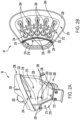
Fig. 2b is a top view of a second tank; -
Fig. 3 is a rear view of a second tank; -
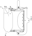
Fig. 4 is a front view of the second tank ofFig. 3 ; -
Fig. 5 is a side view of the second tank ofFig. 3 ; -
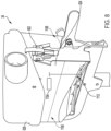
Fig. 6 is an elevated perspective view of the second tank ofFig. 3 ; -
Fig. 7 is a front view of a second tank with a status indicator, two sensors, and a controller; -
Fig. 8 is a side view of a second tank with one sensor; and -
Fig. 9 is a rear perspective view of a second tank and a load cell. - The embodiments of the present disclosure described below are not intended to be exhaustive or to limit the disclosure to the precise forms in the following detailed description. Rather, the embodiments are chosen and described so that others skilled in the art may appreciate and understand the principles and practices of the present disclosure.
- Referring to
Fig. 1 , aseeder assembly 2 is illustrated. Theseeder assembly 2 may include a seeder 4, a tractor 6, and one or morefirst tanks chassis 28 with afirst end 42 and a second end 44, aseeder wheel 30, a firmingwheel 40, arow unit 48, athird tank 46, and asecond tank 34. Thefirst end 42 of thechassis 28 may be coupled to the tractor 6, and the second end 44 of thechassis 28 may be coupled to one or morefirst tanks first tanks first tanks first tanks seeder assembly 2 is contemplated in this disclosure. - The
row unit 48 may be coupled to thefirst end 42 of thechassis 28. Therow unit 48 may also be coupled to thethird tank 46. Therow unit 48 may be configured to receive an air and material mixture from thethird tank 46 and distribute the material in theground 50. In some examples, the material may be seed. In other examples, the material may be fertilizer or pesticide. While certain materials are disclosed herein, it should be understood that any type of agricultural material may be distributed with theseeder assembly 2. - The
third tank 46 may be coupled to theseeder chassis 28. Thethird tank 46 may also be coupled to therow unit 48. In one example, thethird tank 46 and therow unit 48 may be coupled with adistribution line 36. In another example, thethird tank 46 may be coupled to the top of therow unit 48, and thethird tank 46 may distribute the air and material mixture into therow unit 48 without adistribution line 36. Thethird tank 46 may also be coupled to thesecond tank 34. In some embodiments, thethird tank 46 and thesecond tank 34 may be coupled via adistribution line 36. Thethird tank 46 may be configured to receive the air and material mixture from thesecond tank 34 and to distribute the air and material mixture to therow unit 48. - As illustrated in
Fig. 1 , theseeder chassis 28 may have a plurality ofrow units 48 coupled thereto. Therow units 48 may distribute seed into anunderlying ground 50. More specifically, therow unit 48 may selectively cut an opening or furrow into theground 50 and distribute material into the opening or furrow. The firmingwheel 40 may then cover the opening or furrow after the material has been distributed. Therow unit 48 may have a sensor (not pictured) that counts the amount of material distributed from therow unit 48. In one embodiment, therow unit 48 may be coupled to thefirst end 42 of thechassis 28. In other embodiments, therow unit 48 may be coupled to both or between thefirst end 42 and the second end 44 of thechassis 28. In still another embodiment, therow unit 48 may be coupled to the second end 44 of thechassis 28. - The
second tank 34 may be coupled to thechassis 28 of the seeder 4. In one embodiment thesecond tank 34 may be coupled to thechassis 28, such that thesecond tank 28 does not impede the seeder 4 when the seeder 4 is in a folded or transport position. Thesecond tank 34 may be configured to distribute the air and material mixture to thethird tank 46 via adistribution line 36. Thesecond tank 34 may also be coupled to the one or morefirst tanks flow passage 32, such as a hose or distribution line. Thesecond tank 34 may be configured to receive the air and material mixture from the one or morefirst tanks - One or more
first tanks first tanks chassis 10, one or morefirst tanks more wheels 20, ametering system 24, and a pneumatic distribution system 26. The one or morefirst tanks tanks tanks door 22 may releasably seal an opening at an upper end 52 of the one or morefirst tanks first tanks - The
metering system 24 may include one or more meters (not pictured), louvers (not pictured), one or more motors (not pictured) a meter controller, and a sensor (not pictured). Each meter (not pictured) may include louvers that may be coupled to the motor and the louvers may be located within the housing. The louvers may turn via the motor within the housing. The louvers may move in a rotational direction within the housing. In one embodiment, material may enter the housing, travel at least partially around the housing being directed by the louvers and the housing, and the material may exit the housing, being controllably distributed into the pneumatic distribution system 26. Themetering system 24 may be configured to controllably move material from thetanks metering system 24 may be located at a lower end 54 of eachtank metering system 24 may distribute the material from thetanks metering system 24. The meters may be coupled to a controller 710 (seeFig. 7 ) on thesecond tank 34, such that thecontroller 710 provides input to the meters which regulates their speed, and therefore the corresponding fill level in thesecond tank 34. In one embodiment, thecontroller 710 communicates directly with the meters. In another embodiment, the meters may be coupled to a meter controller and thecontroller 710 communicates with the meter controller. In this embodiment, the meter controller may control the rate at which the meters distribute material. In some embodiments, the meter controller may utilize a look-up table to regulate the rate at which the meters distribute material. - The pneumatic distribution system 26 may include a fan (not pictured) coupled to a product delivery conduit structure, wherein the product delivery conduit structure may have
multiple flow passages 32. The fan may create airstreams that direct air through theflow passages 32. In some embodiments, the material may be distributed from the one or morefirst tanks flow passages 32 via themetering system 24. In these embodiments, the airstreams created from the fan may move through theflow passages 32, and these airstreams may move the material through theflow passages 32 to thesecond tank 34. - Referring now to
Figs. 2A and 2B , thesecond tank 34 may include atop end 206 and abottom end 208. Thesecond tank 34 may further include aninlet 202, one ormore outlets 204, afirst chamber 210, afirst level 212, afirst wall 228, asecond chamber 214, asecond level 216, asecond wall 230, ascreen 218, and alid 226. - The
inlet 202 may be located near thetop end 206 of thesecond tank 34. In one embodiment, theinlet 202 may be defined in aradial side 224 of the second tank 112. In another embodiment, theinlet 202 may be located near thetop end 206 of thesecond tank 34 and may enter thesecond tank 34 through thetop end 206 of thesecond tank 34. Theinlet 202 may be configured to receive the air and material mixture from the one or morefirst tanks first chamber 210 of thesecond tank 34. - The
first chamber 210 may be defined by thefirst level 212, thefirst wall 228, thescreen 218, and thelid 226. Thefirst level 212 may be located at or near thebottom end 208 of thesecond tank 34. In one embodiment, thefirst level 212 is the bottom portion of thefirst chamber 210. Thefirst level 212 may be coupled to thefirst wall 228. Thefirst wall 228 may radially surround thefirst level 212. Thefirst wall 228 may extend from thefirst level 212 to thelid 226 of thesecond tank 34 along each side except for ashort side 232. Theshort side 232 of thefirst wall 228 may not extend completely to thelid 226. In other words, theshort side 232 may be located closer to thebottom end 208 of thesecond tank 34 than thefirst wall 228. Theshort side 232 of thefirst wall 228 may be configured to be removable coupled to thescreen 218. In one embodiment, when thescreen 218 is coupled to theshort side 232, there may be a gap (not pictured) between the first end of thescreen 222 and thelid 226. This gap (not pictured) may be configured so material may travel over thescreen 218 and into thesecond chamber 214. - The
screen 218 may partially partition thefirst chamber 210 from thesecond chamber 214. Thescreen 218 may have afirst end 222 and asecond end 220, and thesecond end 220 of thescreen 218 may be coupled to theshort side 232 of thesecond tank 34. Thefirst end 222 of thescreen 218 may be located closer to thetop end 206 of the second tank relative to thesecond end 220 of thescreen 218. Thescreen 218 may be configured such that both thefirst end 222 andsecond end 220 are located below theinlet 202. In other words, both thefirst end 222 andsecond end 220 of thescreen 218 may be located closer to thebottom end 208 of thesecond tank 34 than theinlet 202. In one embodiment, thescreen 218 may be configured such that it is in a vertical position. In some embodiments, thescreen 218 may have one or more holes in it. In one example of this embodiment, the holes in thescreen 218 may be configured such that air may pass through the holes in thescreen 218 but the material may not pass through the holes. In another embodiment, thescreen 218 may include a system of intersecting members, such as a mesh, wherein the air may pass through the mesh but the material may not pass through the mesh. - The
second chamber 214 may comprise asecond level 216, and asecond wall 230. In one example, thesecond chamber 214 may be defined by thesecond wall 230, thesecond level 216, thescreen 218, and the short side of thefirst wall 232. Thesecond chamber 214 may be coupled to thefirst chamber 210. In one embodiment, as illustrated inFig. 2A , thefirst wall 228 may be configured from one or more components, and thesecond wall 230 may be configured from one or more components. In another example, thefirst wall 228 and thesecond wall 230 may be configured from one component, wherein thefirst wall 228 andsecond wall 230 refer to different portions of this one component. Thesecond chamber 214 may be configured to receive air and material from thefirst chamber 210 and to direct the air and material to the one ormore outlets 214. - In one example, the material and air mixture may enter the
first chamber 210 through theinlet 202. The material may drop to thefirst level 212, and the air may exit thefirst chamber 210 by passing through thescreen 218 or by passing through the gap (not pictured) formed between thefirst end 222 of thescreen 218 and thelid 226. As the air and material mixture continues to enter thefirst chamber 210, the material may form a collect on thefirst level 212, and the height of the collected material may rise in the direction towards thetop end 206 of thesecond tank 34. While the highest portion of the material collection may be below thefirst end 222 of thescreen 218, the material may be constrained to thefirst chamber 210. In some embodiments, the height of the material collection may rise above thefirst end 222 of thescreen 218. In these embodiments, the material located above thefirst end 222 of thescreen 218 may move to thesecond chamber 214 through the gap (not pictured) formed between thefirst end 222 of thescreen 218 and thelid 226. In one example, the material may be moved from thefirst chamber 210 to thesecond chamber 214 by the air that is passing from thefirst chamber 210 to thesecond chamber 214. In another example, the material may be moved from thefirst chamber 210 to thesecond chamber 214 by gravity. In still another example, the material may be moved from thefirst chamber 210 to thesecond chamber 214 by an external force, (e.g. a fan). In another example, the material may be moved from thefirst chamber 210 to thesecond chamber 214 by one or more of air, gravity, and an external force. - In some embodiments, the material may substantially cover the
screen 218 and inhibit air from passing through thescreen 218. In these embodiments, the air may pass from thefirst chamber 210 to thesecond chamber 214 by passing between the gap formed between thefirst end 222 of thescreen 218 and thelid 226. - After passing through the gap, the air and material may move into the
second chamber 214. The air traveling through thesecond chamber 214 may move the material out of the second chamber, and the air and material may exit thesecond chamber 214 via one ormore outlets 204. In one embodiment, more material may enter thesecond chamber 214 than material that exits thesecond chamber 214. In this embodiment, material may collect on thesecond level 216. In another embodiment, thesecond chamber 214 may have a collection of material located on thesecond level 216. In this embodiment, more material may exit thesecond chamber 214 than material that enters thesecond chamber 214, and the pile of material may be reduced. In another embodiment, little to no material may enter thesecond chamber 214, but the air may enter thesecond chamber 214 and exit through one ormore outlets 204. - In one embodiment, the
short side 232 of thefirst wall 228 may have one or more through-holes or openings, and thefirst wall 228 may additionally have one or more through-holes or openings that are not located in theshort side 232. In this embodiment, afirst end 234 of theoutlets 204 may extend through the one or more through-holes in theshort side 232. Theoutlets 204 may continue extending through thefirst chamber 210, and asecond end 236 of theoutlets 204 may extend through the through-holes in thefirst wall 228 that are not located in theshort side 232. In another embodiment, thefirst end 234 of theoutlets 204 may be coupled to thefirst chamber 210 at theshort side 232 of thefirst wall 228. Theoutlets 204 may extend through thefirst chamber 210, and thesecond end 236 of theoutlets 204 may exit thefirst chamber 210 through thefirst wall 228. In this embodiment, theshort side 232 of thefirst wall 228 may have one or more through-holes configured such that air and material may move from thesecond chamber 214 into the first end of theoutlets 234. Thefirst wall 228 may also have one or more through-holes located near thesecond end 236 of theoutlet 236 configured such that theoutlets 204 may extend through the through-holes or openings and may exit thefirst chamber 210. - In some embodiments, the
outlets 204 are configured so air and material may move from thesecond chamber 214, into thefirst end 234 of theoutlet 204, move through theoutlet 204 towards thesecond end 236 of theoutlet 204, and move out of thesecond end 236 of theoutlet 204. Thesecond end 236 of theoutlet 204, for example, may be coupled to thethird tank 46. In one embodiment, theoutlet 204 may be coupled to thethird tank 46 via adistribution line 36. In some embodiments, thesecond end 236 of one ormore outlets 204 may be coupled to one or more Y-connectors, and each Y-connector may be coupled to a pair ofthird tanks 46 bydistribution lines 36. In some embodiments, thesecond end 236 of one ormore outlets 204 may be coupled to one or more double Y-connectors, and each double Y-connector may be coupled to at least threethird tanks 46 bydistribution lines 36. In another embodiment, theoutlets 204 may be coupled to a connector that splits into more than three outlets, wherein oneoutlet 204 may distribute into three or morethird tanks 46. - In one embodiment, each
second tank 34 may have one ormore outlets 204. In another embodiment, eachsecond tank 34 may have a plurality ofoutlets 204. In another embodiment, eachsecond tank 34 may have threeoutlets 204. - In
Fig. 1 , thethird tank 46 may be a container that includes an air outlet (not pictured), a material outlet (not pictured), atop end 56, and abottom end 58. Thethird tank 46 may be configured such that it may receive, store, and distribute air and material. Thethird tank 46 may be a hopper, bin, box, or any other type of container. In one embodiment, the air outlet may be located at a radial side of thethird tank 46 near thetop end 56 thereof. In another embodiment, the air outlet may be located on thetop end 56 thereof. The air outlet may be configured to allow air to exit thethird tank 46, and it may further be configured so material may not exit the third tank through the air outlet. In one embodiment, the material outlet may be located at a radial side of thethird tank 46 near thebottom end 58 thereof. In another embodiment, the material outlet may be located on thebottom end 58 thereof. The material outlet may be configured such that either air, material, or a combination thereof may exit thethird tank 46 through said nozzle. As described above, thethird tank 46 may be coupled to therow unit 48, and therow unit 48 may receive, store, and distribute material, air, or an air and material mixture into theground 50. - In one embodiment a
second tank 34 may be coupled to more than onethird tank 46, and more material may enter one of thethird tanks 46 than exits therefrom. In this embodiment, material may accumulate and form a collection on thebottom end 58 of thethird tank 46. In one example of this embodiment, the height of the collection may rise towards thetop end 56 of thethird tank 46 until the air outlet is covered by the seed. In this example, material may stop entering thethird tank 46 because there is no airflow to move the seed from thesecond tank 34, through thedistribution line 36, and into thethird tank 46. In this example, the air and material may continue to flow through otherthird tanks 46 that are also connected to thesecond tank 34. In this example, air may not exit onethird tank 46 until material exits anotherthird tank 46 and the air nozzle of the one third tank is at least partially uncovered. In this embodiment, eachthird tank 46 coupled to thesecond tank 34 may operate independently of the otherthird tanks 46 coupled to thesecond tank 34. In one example, none of the air outlets may be covered by material, and material may enter each of thethird tanks 46. In another example, all of thethird tanks 46 that are coupled to thesecond tank 34 may have air outlets that are covered with material, and material may not enter any of thethird tanks 46 until one or more air outlets are at least partially uncovered. In still another example, some of thethird tanks 46 coupled to thesecond tank 34 may have air outlets that are covered with material, and otherthird tanks 46 coupled to thesecond tank 34 may have air outlets that are at least partially uncovered. In this example, material may enter thethird tanks 34 that have an air outlet that is at least partially uncovered, and material may not enter thethird tanks 46 that have an air outlet that is covered. - Referring now to
Figs. 3-6 , thelid 226 may be removably coupled to thesecond tank 34. Thelid 226 may be removably coupled to thesecond tank 34 with one or morelid coupling devices 402. Thelid coupling device 402 may be a hinge latch, latch, button, hook and loop fastener, a belt and buckle fastener, a cinched buckle, a side release clip, or any other device known in the art to secure a lid. In some embodiments, thelid 226 may be rotatably coupled to thesecond tank 34. In other embodiments, the lid may be removably coupled to thesecond tank 34 such that thelid 226 may be lifted off of thesecond tank 34. - Referring now to
Fig. 7 , thesecond tank 34 may include astatus indicator 702, afirst sensor 704, and asecond sensor 706. In one embodiment, the first andsecond sensors radial side 224 of thesecond tank 34. Thefirst sensor 704 may be located at afirst height 712, and the second sensor may be located at asecond height 714, where thefirst height 712 may be greater than thesecond height 714. In other words, thefirst sensor 704 may be closer to thelid 226. In some embodiments, thestatus indicator 702 may be located on thelid 226. In other embodiments, thestatus indicator 702 may be located on an exteriorradial side 224 of thesecond tank 34. Thestatus indicator 702 may provide a notification. The notification may be a visual notification such as, for example, a display of a colored light, a flashing light, and/or providing a notification to an operator of a tractor 6. Thefirst sensor 704 andsecond sensor 706 may detect the level ofmaterial 708 in the tank. The first andsecond sensors controller 710. In one embodiment, the first andsecond sensor material level 708 has reached the corresponding height of thesensor tank 34. The first andsecond sensors - The
controller 710 may receive input from the first andsecond sensor status indicator 702. Thecontroller 710 may include a transmitter capable of providing input to an external device. The controller may receive power from a power source (not pictured). The controller may also provide power to the first andsecond sensors status indicator 702. In one embodiment, thecontroller 710 may be hardwired to a power source, and it may also be hardwired to the first andsecond sensors status indicator 702. In one embodiment, the power source may be a battery. In one embodiment, thefirst sensor 704 may detect no material and thesecond sensor 706 may detect material. In this embodiment, thestatus indicator 702 may provide a first notification indicative of the level ofmaterial 708 in thetank 34. In one example of this embodiment, the first notification may be green flashing lights. In another embodiment, thefirst sensor 704 may detect no material and thesecond sensor 706 may detect no material. In this embodiment, thestatus indicator 702 may provide a second notification. In one example of this embodiment, the second notification may be yellow flashing lights. In another embodiment, thefirst sensor 704 may detect material and thesecond sensor 706 may detect material. In this embodiment, thestatus indicator 702 may provide a third notification. In one example of this embodiment, the third notification may be green lights that are not flashing. In still another embodiment, thefirst sensor 704 may detect material and thesecond sensor 706 may detect no material. In this embodiment, thestatus indicator 702 may provide a fourth notification. In one example of this embodiment, the fourth notification may be red lights that are not flashing. This may be a diagnostic or other notification indicating a problem with one or bothsensors - Referring now to
Fig. 8 , rather than having a first andsecond sensor second tank 34 may have only onesensor 704. In one embodiment, thesensor 704 may be located on an exteriorradial side 224 of thesecond tank 34. In this embodiment, thesensor 704 may be a proximity sensor, and may detect whether thematerial level 708 has reached theheight 712 of thesensor 704. In another embodiment, thesensor 704 may be an ultrasonic sensor. In this embodiment, the sensor may be located on thelid 226, and may detect the height of thefirst material level 708. Thesensor 704 may be any type of sensor capable of detecting a material level in thetank 34. - In some embodiments, the
sensor 704 may have thestatus indicator 702 integrated into it. In this embodiment, in addition to detecting thematerial level 708, thesensor 704 may also provide a notification. In one example of this embodiment, thesensor 704 may be hardwired to an external battery. In another example of this embodiment, thesensor 704 may have an internal battery. The notification provided by thesensor 704 may be a visual notification, such as displaying a colored light, displaying a flashing light, displaying a colored flashing light, and/or providing a notification to an external device. In some embodiments, the notification may be an audible signal. In other embodiments, the notification may be a visual and audible signal. - In another embodiment, the
sensor 704 may not have thestatus indicator 702 integrated into it. In this embodiment, thesensor 704 may communicate with acontroller 710, and thecontroller 710 may communicate with astatus indicator 702. Thecontroller 710 may receive input from thefirst controller 704 and may provide input to thestatus indicator 702. Thecontroller 710 may also provide input to an external device. The controller may be powered by and receive power from a power source. Thecontroller 710 may also provide power to thesensor 704 and thestatus indicator 702. In one embodiment, thecontroller 710 may be hardwired to a power source, thesensor 704, and thestatus indicator 702. In one embodiment, the power source may be a battery. The notification provided by thestatus indicator 702 may be a visual notification such as displaying a colored light, displaying a flashing light, displaying a colored flashing light, and/or providing a notification to an external device. In some embodiments, the notification may be an audible signal. In other embodiments, the notification may be a visual and audible signal. - Referring now to
Fig. 9 , thesecond tank 34 may be coupled to a load cell 902. The load cell 902 may weigh thesecond tank 34 and any other forces upon it. The load cell 902 may be coupled to thecontroller 710. Thecontroller 710 may provide power to the load cell, and the load cell 902 may continuously be measuring the weight upon it. In one embodiment, the load cell 902 may display the weight. In another embodiment, the load cell 902 may provide the weight to thecontroller 710, and the controller may provide the weight to a device. The device may be a display or monitor in the cab of the tractor 6, a mobile or remote device, a stationary device, or any other type of device. - In one embodiment, the
metering system 24 may be calibrated using the first andsecond sensors second tank 34 until thesecond sensor 706 detects material. Then, the number of rotations of themetering system 24 may be detected by a sensor and the material may resume entering thesecond tank 34. In this embodiment, thesecond tank 34 may be filled and the rotations of themetering system 24 may be detected until thefirst sensor 704 detects material. In one example of this embodiment, the rotations of the metering system may counted, or detected, by a sensor (not pictured). - In another embodiment, the load cell 902 may calibrate the
metering system 24 using asingle sensor 704. In this embodiment, the volume of thesecond tank 34 below thesensor 704 may be either known or measured. In one example of this embodiment, the weight of the emptysecond tank 34 may be measured with the load cell 902. In another example of this embodiment, the weight of thesecond tank 34 may be measured when there is a known volume or known amount of material in thesecond tank 34. In this embodiment, material then resumes entering thesecond tank 34, and as material is distributed into thesecond tank 34, the rotations of themetering system 24 may be counted or detected by another sensor. When thesensor 704 detects material, material may stop being distributed and the number of rotations of the metering system may be provided. - While embodiments incorporating the principles of the present disclosure have been described hereinabove, the present disclosure is not limited to the described embodiments. Instead, this application is intended to cover any variations, uses, or adaptations of the disclosure using its general principles. Further, this application is intended to cover such departures from the present disclosure as come within known or customary practice in the art to which this disclosure pertains and which fall within the limits of the appended claims.
Claims (15)
- A seeder assembly (2) for dispensing product, comprising:a chassis (28) having a first end (42) and a second end (44);a row unit (48) coupled to the chassis (28);a first tank (12, 14, 16, 18) configured to contain a product, wherein the first tank (12, 14, 16, 18) is disposed along a flow path;a second tank (34) fluidly coupled to the first tank (12, 14, 16, 18) via the flow path, wherein the second tank (34) is configured to receive product from the first tank (12, 14, 16, 18);a third tank (46) fluidly coupled to the second tank (34) via the flow path, wherein the third tank (46) is configured to receive product from the second tank (34);an inlet (202) fluidly coupled to the first tank (12, 14, 16, 18) via the flow path; andan outlet (204) fluidly coupled to the inlet (202), the outlet (204) being fluidly coupled to the third tank (46) via the flow path;wherein the row unit (48) is fluidly coupled via the flow path to the third tank (46);wherein the row unit (48) is configured to dispense product that is received from the third tank (46) via the flow path.
- The seeder assembly (2) of claim 1, wherein the second tank (34) further comprises:a first chamber (210) fluidly coupled to the inlet (202);a second chamber (214) fluidly coupled to the first chamber (210) and the outlet (214); anda screen (218) with a first end (222) and a second end (220), wherein the second end (220) of the screen (218) is located at least partially in the first chamber (210), and the first end (222) of the screen (218) is located above the second end (220);wherein the screen (218) partially separates the first chamber (210) from the second chamber (214);wherein the inlet (202) is located at or above the screen (218).
- The seeder assembly (2) of claim 1 or 2, wherein the outlet (204) is fluidly coupled to two or more third tanks (46).
- The seeder assembly (2) of one of the claims 1 to 3, further comprising a meter (24) coupled to the first tank (12, 14, 16, 18);wherein the meter (24) is coupled between the first tank (12, 14, 16, 18) and the flow path;wherein the meter (24) is configured to control the flow of product distributed from the first tank (12, 14, 16, 18) to the flow path;wherein the meter (24) is coupled to a controller, and the controller is configured to control the meter (24).
- The seeder assembly (2) of one of the claims 2 to 4, further comprising a first sensor (704) coupled to the second tank (34) on the first chamber (210);
wherein the first sensor (704) is configured to detect when the product collected in the first chamber (210) reaches a first height (712). - The seeder assembly (2) of claim 4 or 5, further comprising:a first controller coupled to the meter (24), wherein the first controller is configured to control an output of the meter (24);a second controller (710) coupled to the first sensor (704); anda status indicator (702) in communication with the second controller (710);wherein the second controller (710) receives an input from the first sensor (704), and the second controller (710) is configured to send the input to the status indicator (702);wherein the second controller (710) is configured to communicate an input to the first controller;wherein the first controller receives the input from the second controller (710) and communicates an output to the meter (24);wherein the output to the meter (24) is configured to regulate a rate at which product is distributed from the first tank (12, 14, 16, 18) into the flow path.
- The seeder assembly (2) of claim 5 or 6, further comprising:a second sensor (706) coupled to the second tank (34) in the first chamber (210);wherein the second sensor (706) is configured to detect when the product collected in the first chamber (210) reaches a second height (714);further wherein the first height (712) is greater than the second height (714).
- The seeder assembly (2) of claim 7, further comprising:the first controller (710) coupled to the first and second sensors (704, 706);the status indicator (702) coupled to the first controller (710);the second controller coupled to and disposed in communication with the meter (24); and a third sensor coupled to the row unit (48);wherein the first controller (710) is configured to receive input from the first or second sensor (704, 706);wherein the first controller (710) is configured to communicate the input to the status indicator (702);wherein the first controller (710) is configured to communicate an input to the second controller;wherein the second controller is configured to receive the input from the first controller (710) and sends the input to the meter (24);wherein the input from the second controller is configured to regulate the rate at which the product is distributed from the first tank (12, 14, 16, 18) into the flow path;wherein the third sensor is configured to determine an amount of product being distributed from the row unit (48).
- The seeder assembly (2) of one of the claims 1 to 8, further comprising a load cell (902) coupled to the second tank (34), wherein the load cell (902) is configured to detect a force applied to it.
- A method for distributing product from a seeder assembly (2) according to one of the claims 1 to 9, the method comprising:providing a first tank (12, 14, 16, 18), a second tank (34), a third tank (46), a row unit (48), and a fan;storing the product in the first tank (12, 14, 16, 18);producing a fluid flow in a flow path between the first tank (12, 14, 16, 18) and the row unit (48) via the fan;dispensing product from the first tank (12, 14, 16, 18) into the airflow and to the second tank (34) via the flow path;transferring product from the second tank (34) to the third tank (46) via the flow path;sending product from the third tank (46) to the row unit (48) via the flow path; andreleasing product from the row unit (48) to an underlying ground (50).
- The method of claim 10, wherein the dispensing product comprises:passing the product through an inlet (202) and into a first chamber (210) of the second tank (34) via the flow path;collecting product in the first chamber (210) until the product reaches a height of the screen (218);moving product to a second chamber (214) of the second tank (34) when product in the first chamber (210) exceeds the height of the screen (218); andflowing product out of an outlet (204) of the second tank (34) via the flow path.
- The method of claim 10 or 11, further comprising:detecting via a first sensor (704) an amount of product collecting in the first chamber (210);communicating the amount of product collected in the first chamber (210) to a status indicator (702) via the first sensor (704); andoutputting the amount of product in the first chamber (210) via the status indicator (702).
- The method of one of the claims 10 to 12, further comprising:detecting via a second sensor (706) the amount of product collected in the first chamber (210);communicating the amount of product in the first chamber (210) via the second sensor (706) to the status indicator (702).
- A tank (34) for a seeder assembly (2) comprising:an inlet (202) and an outlet (204);a first chamber (210) fluidly coupled to the inlet (202);a second chamber (214) fluidly coupled between the first chamber (210) and the outlet (204); anda screen (218) with a first end (222) and a second end (220), the screen (218) being located between the first chamber (210) and the second chamber (214) and the first end (222) thereof being located above the second end (220);wherein the screen (218) partially separates the first chamber (210) from the second chamber (214);wherein the inlet (202) is located at or above the first end (222) of the screen (218).
- The tank (34) of claim 14, further comprising:a first sensor (704) coupled to the tank (34) and configured to detect when product reaches a first threshold level (712); anda second sensor (706) coupled to the tank (34) and configured to detect when product reaches a second threshold level (714).
Applications Claiming Priority (1)
| Application Number | Priority Date | Filing Date | Title |
|---|---|---|---|
| US17/981,782 US20240147895A1 (en) | 2022-11-07 | 2022-11-07 | Air seeder pneumatic control system |
Publications (1)
| Publication Number | Publication Date |
|---|---|
| EP4364550A1 true EP4364550A1 (en) | 2024-05-08 |
Family
ID=88295651
Family Applications (1)
| Application Number | Title | Priority Date | Filing Date |
|---|---|---|---|
| EP23202052.9A Pending EP4364550A1 (en) | 2022-11-07 | 2023-10-06 | Seeder assembly, method for distributing product and tank |
Country Status (4)
| Country | Link |
|---|---|
| US (1) | US20240147895A1 (en) |
| EP (1) | EP4364550A1 (en) |
| AU (1) | AU2023226716A1 (en) |
| CA (1) | CA3216176A1 (en) |
Cited By (2)
| Publication number | Priority date | Publication date | Assignee | Title |
|---|---|---|---|---|
| EP4649806A1 (en) * | 2024-05-15 | 2025-11-19 | Amazonen-Werke H. Dreyer SE & Co. KG | Method for operating an agricultural application machine and agricultural application machine |
| EP4649803A1 (en) * | 2024-05-15 | 2025-11-19 | Amazonen-Werke H. Dreyer SE & Co. KG | Distribution system for an agricultural application machine, agricultural application machine and method for distributing application material |
Citations (7)
| Publication number | Priority date | Publication date | Assignee | Title |
|---|---|---|---|---|
| US20070113764A1 (en) * | 2004-01-12 | 2007-05-24 | Patrick Audette | Seed and fertilizer drill and method |
| EP2417846A1 (en) * | 2010-08-12 | 2012-02-15 | Deere & Company | Method of operating a distribution apparatus |
| US20120316736A1 (en) * | 2011-06-10 | 2012-12-13 | Great Plains Manufacturing, Incorporated | Cultivation air seeder having sequentially operated tools |
| EP3150043A1 (en) * | 2015-09-30 | 2017-04-05 | Deere & Company | System for distributing a plurality of seeds |
| EP3150041A1 (en) * | 2015-09-30 | 2017-04-05 | Deere & Company | Seeding system |
| US20200053955A1 (en) * | 2016-10-11 | 2020-02-20 | Deere & Company | Seeding system |
| WO2022056616A1 (en) * | 2020-09-16 | 2022-03-24 | Clean Seed Agricultural Technologies Ltd. | Bulk transfer delivery system for multiple agricultural products |
Family Cites Families (23)
| Publication number | Priority date | Publication date | Assignee | Title |
|---|---|---|---|---|
| US6213690B1 (en) * | 1999-03-30 | 2001-04-10 | Deere & Company | Distribution manifold for air seeder |
| US6158363A (en) * | 1999-05-21 | 2000-12-12 | Flexi-Coil Ltd. | Apparatus for dispensing particles |
| US6688244B1 (en) * | 2002-08-08 | 2004-02-10 | Deere & Company | Product on demand delivery system |
| US6935256B1 (en) * | 2004-05-05 | 2005-08-30 | Deere & Company | Agitation system for an agricultural machine product distribution system |
| US8544498B2 (en) * | 2010-06-23 | 2013-10-01 | Deere & Company | Manifold and distribution manifold assembly for air-entrained material |
| US8635963B2 (en) * | 2011-01-06 | 2014-01-28 | Cnh Canada, Ltd. | Method and apparatus for sectional control of air seeder distribution system for a farm implement |
| US8821078B2 (en) * | 2011-01-07 | 2014-09-02 | Conagra Foods Lamb Weston, Inc. | Fluid-based article distribution and sorting system |
| US10321624B2 (en) * | 2011-03-11 | 2019-06-18 | Intelligent Agriculture Solutions LLC | Air seeder manifold system |
| US20160246296A1 (en) * | 2011-03-11 | 2016-08-25 | Intelligent Agricultural Solutions, Llc | Gateway system and method |
| CA2741267C (en) * | 2011-05-27 | 2013-10-15 | Bourgault Industries Ltd. | Air distribution for an air seeder |
| CA2756635A1 (en) * | 2011-11-01 | 2013-05-01 | Straw Track Manufacturing Inc. | Air seeder manifold apparatus |
| DE102013215183B3 (en) * | 2013-08-01 | 2014-09-11 | Horsch Maschinen Gmbh | Process for dosing granular material and granular dosing device |
| US20190307057A1 (en) * | 2013-09-30 | 2019-10-10 | Precision Planting Llc | Methods and systems for seed variety selection |
| WO2015048817A1 (en) * | 2013-09-30 | 2015-04-02 | Precision Planting Llc | Methods and systems for seed variety selection |
| US9585304B2 (en) * | 2014-10-17 | 2017-03-07 | Cnh Industrial America Llc | 3-way seed flow splitter for planters |
| US9826676B2 (en) * | 2015-09-30 | 2017-11-28 | Deere & Company | Seed dispersion unit |
| CA2947428C (en) * | 2016-11-04 | 2018-12-11 | Bourgault Industries Ltd. | Air seeder distribution apparatus with purging air |
| US12041871B2 (en) * | 2018-09-07 | 2024-07-23 | Precision Planting Llc | Apparatus, system and method for monitoring and mapping air seeder performance |
| US11733719B2 (en) * | 2018-10-16 | 2023-08-22 | Cnh Industrial Canada, Ltd. | User access management for dispensing particulate material |
| US11154004B2 (en) * | 2019-04-26 | 2021-10-26 | Deere & Company | Agricultural seed sensing and control system |
| CA3047567C (en) * | 2019-06-25 | 2021-07-13 | Bourgault Industries Ltd. | Implement frame mounted product meters |
| US11576300B2 (en) * | 2020-02-12 | 2023-02-14 | Vaderstad Llc | Operator speed guidance for an agricultural product application system |
| US11839174B2 (en) * | 2021-04-28 | 2023-12-12 | Cnh Industrial America Llc | Product delivery conduit for an agricultural product hopper assembly |
-
2022
- 2022-11-07 US US17/981,782 patent/US20240147895A1/en active Pending
-
2023
- 2023-09-07 AU AU2023226716A patent/AU2023226716A1/en active Pending
- 2023-10-06 CA CA3216176A patent/CA3216176A1/en active Pending
- 2023-10-06 EP EP23202052.9A patent/EP4364550A1/en active Pending
Patent Citations (7)
| Publication number | Priority date | Publication date | Assignee | Title |
|---|---|---|---|---|
| US20070113764A1 (en) * | 2004-01-12 | 2007-05-24 | Patrick Audette | Seed and fertilizer drill and method |
| EP2417846A1 (en) * | 2010-08-12 | 2012-02-15 | Deere & Company | Method of operating a distribution apparatus |
| US20120316736A1 (en) * | 2011-06-10 | 2012-12-13 | Great Plains Manufacturing, Incorporated | Cultivation air seeder having sequentially operated tools |
| EP3150043A1 (en) * | 2015-09-30 | 2017-04-05 | Deere & Company | System for distributing a plurality of seeds |
| EP3150041A1 (en) * | 2015-09-30 | 2017-04-05 | Deere & Company | Seeding system |
| US20200053955A1 (en) * | 2016-10-11 | 2020-02-20 | Deere & Company | Seeding system |
| WO2022056616A1 (en) * | 2020-09-16 | 2022-03-24 | Clean Seed Agricultural Technologies Ltd. | Bulk transfer delivery system for multiple agricultural products |
Cited By (2)
| Publication number | Priority date | Publication date | Assignee | Title |
|---|---|---|---|---|
| EP4649806A1 (en) * | 2024-05-15 | 2025-11-19 | Amazonen-Werke H. Dreyer SE & Co. KG | Method for operating an agricultural application machine and agricultural application machine |
| EP4649803A1 (en) * | 2024-05-15 | 2025-11-19 | Amazonen-Werke H. Dreyer SE & Co. KG | Distribution system for an agricultural application machine, agricultural application machine and method for distributing application material |
Also Published As
| Publication number | Publication date |
|---|---|
| US20240147895A1 (en) | 2024-05-09 |
| CA3216176A1 (en) | 2024-05-07 |
| AU2023226716A1 (en) | 2024-05-23 |
Similar Documents
| Publication | Publication Date | Title |
|---|---|---|
| CA3216176A1 (en) | Air seeder pneumatic control system | |
| US11032965B2 (en) | Pneumatic spreading machine and method for controlling or regulating the metering elements thereof by carrying out calibration tests | |
| AU2015200000B2 (en) | Sensor for air cart metering system | |
| CN116437799A (en) | Air Freight Cart with Modular Dosing System | |
| US6193175B1 (en) | Agricultural particulate material delivery system | |
| US8695396B2 (en) | Method of calibrating the meter of a product distribution apparatus and monitoring method | |
| BRPI1107084A2 (en) | Product Dispenser, and Method for Calibrating a Dispenser on a Product Dispenser | |
| CA2911580A1 (en) | Air flow control for delivery of agricultural products | |
| BR102020017336A2 (en) | methods to identify raw material flow and the location of blockage in a batcher set and to identify a raw material blockage | |
| US20230389464A1 (en) | Grain-Singulating Apparatus with Separating Device, and Seeder with Grain-Singulating Apparatus | |
| CN109477317A (en) | Particulate material dispensing apparatus and method | |
| BR102023015867A2 (en) | SEEDING SET FOR DISPENSING PRODUCT, METHOD FOR DISTRIBUTING PRODUCT FROM A SEEDING SET, AND, TANK FOR A SEEDING SET | |
| CN116456819A (en) | Metering group for an air vehicle | |
| JPH0484846A (en) | Pesticide applicator |
Legal Events
| Date | Code | Title | Description |
|---|---|---|---|
| PUAI | Public reference made under article 153(3) epc to a published international application that has entered the european phase |
Free format text: ORIGINAL CODE: 0009012 |
|
| STAA | Information on the status of an ep patent application or granted ep patent |
Free format text: STATUS: THE APPLICATION HAS BEEN PUBLISHED |
|
| AK | Designated contracting states |
Kind code of ref document: A1 Designated state(s): AL AT BE BG CH CY CZ DE DK EE ES FI FR GB GR HR HU IE IS IT LI LT LU LV MC ME MK MT NL NO PL PT RO RS SE SI SK SM TR |
|
| STAA | Information on the status of an ep patent application or granted ep patent |
Free format text: STATUS: REQUEST FOR EXAMINATION WAS MADE |
|
| 17P | Request for examination filed |
Effective date: 20241108 |
|
| RBV | Designated contracting states (corrected) |
Designated state(s): AL AT BE BG CH CY CZ DE DK EE ES FI FR GB GR HR HU IE IS IT LI LT LU LV MC ME MK MT NL NO PL PT RO RS SE SI SK SM TR |