EP4362291A1 - Motor unit - Google Patents
Motor unit Download PDFInfo
- Publication number
- EP4362291A1 EP4362291A1 EP22828008.7A EP22828008A EP4362291A1 EP 4362291 A1 EP4362291 A1 EP 4362291A1 EP 22828008 A EP22828008 A EP 22828008A EP 4362291 A1 EP4362291 A1 EP 4362291A1
- Authority
- EP
- European Patent Office
- Prior art keywords
- oil
- motor cover
- motor
- rotor shaft
- stator
- Prior art date
- Legal status (The legal status is an assumption and is not a legal conclusion. Google has not performed a legal analysis and makes no representation as to the accuracy of the status listed.)
- Withdrawn
Links
Images


Classifications
-
- H—ELECTRICITY
- H02—GENERATION; CONVERSION OR DISTRIBUTION OF ELECTRIC POWER
- H02K—DYNAMO-ELECTRIC MACHINES
- H02K9/00—Arrangements for cooling or ventilating
- H02K9/26—Structural association of machines with devices for cleaning or drying cooling medium, e.g. with filters
-
- H—ELECTRICITY
- H02—GENERATION; CONVERSION OR DISTRIBUTION OF ELECTRIC POWER
- H02K—DYNAMO-ELECTRIC MACHINES
- H02K1/00—Details of the magnetic circuit
- H02K1/06—Details of the magnetic circuit characterised by the shape, form or construction
- H02K1/22—Rotating parts of the magnetic circuit
- H02K1/32—Rotating parts of the magnetic circuit with channels or ducts for flow of cooling medium
-
- H—ELECTRICITY
- H02—GENERATION; CONVERSION OR DISTRIBUTION OF ELECTRIC POWER
- H02K—DYNAMO-ELECTRIC MACHINES
- H02K3/00—Details of windings
- H02K3/04—Windings characterised by the conductor shape, form or construction, e.g. with bar conductors
- H02K3/24—Windings characterised by the conductor shape, form or construction, e.g. with bar conductors with channels or ducts for cooling medium between the conductors
-
- H—ELECTRICITY
- H02—GENERATION; CONVERSION OR DISTRIBUTION OF ELECTRIC POWER
- H02K—DYNAMO-ELECTRIC MACHINES
- H02K5/00—Casings; Enclosures; Supports
- H02K5/04—Casings or enclosures characterised by the shape, form or construction thereof
- H02K5/20—Casings or enclosures characterised by the shape, form or construction thereof with channels or ducts for flow of cooling medium
- H02K5/203—Casings or enclosures characterised by the shape, form or construction thereof with channels or ducts for flow of cooling medium specially adapted for liquids, e.g. cooling jackets
-
- H—ELECTRICITY
- H02—GENERATION; CONVERSION OR DISTRIBUTION OF ELECTRIC POWER
- H02K—DYNAMO-ELECTRIC MACHINES
- H02K7/00—Arrangements for handling mechanical energy structurally associated with dynamo-electric machines, e.g. structural association with mechanical driving motors or auxiliary dynamo-electric machines
- H02K7/10—Structural association with clutches, brakes, gears, pulleys or mechanical starters
- H02K7/116—Structural association with clutches, brakes, gears, pulleys or mechanical starters with gears
-
- H—ELECTRICITY
- H02—GENERATION; CONVERSION OR DISTRIBUTION OF ELECTRIC POWER
- H02K—DYNAMO-ELECTRIC MACHINES
- H02K9/00—Arrangements for cooling or ventilating
- H02K9/19—Arrangements for cooling or ventilating for machines with closed casing and closed-circuit cooling using a liquid cooling medium, e.g. oil
-
- H—ELECTRICITY
- H02—GENERATION; CONVERSION OR DISTRIBUTION OF ELECTRIC POWER
- H02K—DYNAMO-ELECTRIC MACHINES
- H02K9/00—Arrangements for cooling or ventilating
- H02K9/19—Arrangements for cooling or ventilating for machines with closed casing and closed-circuit cooling using a liquid cooling medium, e.g. oil
- H02K9/193—Arrangements for cooling or ventilating for machines with closed casing and closed-circuit cooling using a liquid cooling medium, e.g. oil with provision for replenishing the cooling medium; with means for preventing leakage of the cooling medium
-
- Y—GENERAL TAGGING OF NEW TECHNOLOGICAL DEVELOPMENTS; GENERAL TAGGING OF CROSS-SECTIONAL TECHNOLOGIES SPANNING OVER SEVERAL SECTIONS OF THE IPC; TECHNICAL SUBJECTS COVERED BY FORMER USPC CROSS-REFERENCE ART COLLECTIONS [XRACs] AND DIGESTS
- Y02—TECHNOLOGIES OR APPLICATIONS FOR MITIGATION OR ADAPTATION AGAINST CLIMATE CHANGE
- Y02T—CLIMATE CHANGE MITIGATION TECHNOLOGIES RELATED TO TRANSPORTATION
- Y02T10/00—Road transport of goods or passengers
- Y02T10/60—Other road transportation technologies with climate change mitigation effect
- Y02T10/64—Electric machine technologies in electromobility
Definitions
- the present invention relates to motor units, and more specifically, to a motor unit used in an electric vehicle.
- Patent Literature 1 discloses a rotating electrical machine.
- the rotating electrical machine includes a cooling medium path in which a cooling medium for cooling a stator flows, and a cooling medium filter provided in the path of the cooling medium to remove contamination from the cooling medium.
- the cooling medium filter is installed on a top side of a case which houses the stator.
- Patent Literature 1 JP-A 2019-154115
- Patent Literature 1 does not show sufficient consideration to compactly configuring the rotating electrical machine.
- a primary object of the present invention is to provide a motor unit which can be configured compactly.
- a motor unit which includes a case having a stator housing, a first motor cover provided at an output side end portion of the stator housing, and a second motor cover provided at a non-output side end portion of the stator housing; a rotor provided inside the case and having a rotor shaft; a stator provided inside the case and having a stator core provided radially outside the rotor and a stator coil provided in the stator core; and an oil filter provided on an outer surface of the first motor cover for filtration of oil to be supplied into the case; wherein at least part of a lower half of the oil filter overlaps with an upper half of the stator core when viewed axially along the rotor shaft.
- the oil filter is provided on the outer surface of the first motor cover so that at least part of the lower half of the oil filter overlaps with the upper half of the stator core when viewed axially along the rotor shaft.
- the motor unit further includes a speed reducer provided on a side of the first motor cover in order to slow down rotation of the rotor and including an oil reservoir storing oil from the case, and an oil pump provided on an outer surface of the speed reducer in order to discharge oil out of the oil reservoir.
- a speed reducer provided on a side of the first motor cover in order to slow down rotation of the rotor and including an oil reservoir storing oil from the case
- an oil pump provided on an outer surface of the speed reducer in order to discharge oil out of the oil reservoir.
- the oil pump for discharging oil out of the oil reservoir of the speed reducer is provided on the outer surface of the speed reducer, it is possible to configure the motor unit compactly, including the oil pump.
- the speed reducer further includes an output shaft provided in parallel with the rotor shaft; and with a line segment connecting a center of the rotor shaft and a center of the output shaft being called a reference line, a perpendicular line perpendicular to the reference line and passing the center of the rotor shaft being called a first perpendicular line, and a perpendicular line perpendicular to the reference line and passing the center of the output shaft being called a second perpendicular line; when viewed axially along the rotor shaft, at least part of the oil filter overlaps with a region surrounded by the reference line, the first perpendicular line and the second perpendicular line.
- the region surrounded by the reference line, the first perpendicular line and the second perpendicular line when viewed axially along the rotor shaft is often left as an empty space. Therefore, by providing the oil filter in such a way that at least part of the oil filter overlaps with the region, it becomes possible to make an effective use of the empty space without interfering with other members, and to configure the motor unit compactly.
- the oil filter is at a higher position than the output shaft. In this case, it is possible to configure the motor unit compactly without interfering with output from the output shaft of the speed reducer.
- the oil filter is at a higher position than the rotor shaft.
- the motor unit compactly without interfering with output from the rotor shaft of the rotor.
- a center of the oil filter is at a higher position than an outer circumferential surface of the stator coil. In this case, it is possible to drop oil easily onto the stator coil inside the case via the oil filter.
- the motor unit further includes an externally attached pipe provided outside the stator housing, having an outward oil path for supplying oil which has passed the oil filter into the case, and held by the first motor cover and the second motor cover.
- an externally attached pipe provided outside the stator housing, having an outward oil path for supplying oil which has passed the oil filter into the case, and held by the first motor cover and the second motor cover.
- at least part of the oil filter overlaps with the externally attached pipe when viewed axially along the rotor shaft.
- the region outside the stator housing where the externally attached pipe is provided, and a region adjacent thereto are often left as empty spaces. Therefore, by providing the oil filter in such a way that at least part of the oil filter overlaps with the externally attached pipe when viewed axially along the rotor shaft, it becomes possible to make an effective use of the empty space without interfering with other member, and to configure the motor unit compactly.
- the oil filter has an oil discharge port at an end portion facing the first motor cover, and the first motor cover has an oil path for communication between the oil discharge port and the outward oil path of the externally attached pipe.
- the oil filter has an oil discharge port at an end portion facing the first motor cover, and the first motor cover has an oil path for communication between the oil discharge port and the outward oil path of the externally attached pipe.
- output side end portion of the stator housing refers to an axial end portion of the stator housing from which the motor output is taken off.
- Non-output side end portion of the stator housing refers to an axial end portion of the stator housing from which the motor output is not taken off (an axial end portion on a side away from the output side end portion).
- a motor unit 10 according to an embodiment of the present invention is suitably applied to an electric vehicle.
- the terms front and rear, left and right, and up and down used in the embodiments of the present invention are defined based on a direction in which a rotor 40 (which will be described later) extends as the left-right direction, and a direction from a motor 12 (which will be described later) toward an inverter 16 (which will be described later) as the rearward direction.
- “Fr” indicates forward
- Rr indicates rearward
- R indicates rightward
- L indicates leftward
- U indicates upward
- “Lo” indicates downward.
- the motor unit 10 is a mechatronic integrated unit including the motor 12, a speed reducer 14, and an inverter 16.
- the speed reducer 14 is provided on a side (left side in the present embodiment) of the motor 12, while the inverter 16 is provided behind the motor 12 and the speed reducer 14.
- the motor 12 includes a case 18.
- the case 18 has a three-tier structure, and includes a stator housing 20, a first motor cover 22 provided at an output side end portion of the stator housing 20, and a second motor cover 24 provided at a non-output side end portion of the stator housing 20.
- the second motor cover 24 includes a cover main body 26, and a pipe holder 28 attached to the cover main body 26.
- a branching piece 30 is provided between the cover main body 26 and the pipe holder 28.
- first externally attached pipe 32 held by the first motor cover 22 and the second motor cover 24.
- the first externally attached pipe 32 is a separate member from the stator housing 20, provided slightly spaced away from the stator housing 20, and sandwiched by the first motor cover 22 and the second motor cover 24.
- the first externally attached pipe 32 has an outlet side end portion that is held by the pipe holder 28 and is connected with the branching piece 30.
- an outward oil path 34 which provides communication between the first motor cover 22 and the second motor cover 24.
- second externally attached pipe 36 held by the first motor cover 22 and the second motor cover 24.
- the second externally attached pipe 36 is a separate member from the stator housing 20, provided slightly spaced away from the stator housing 20, and sandwiched by the first motor cover 22 and the second motor cover 24.
- the second externally attached pipe 36 has an inlet side end portion that is held by the pipe holder 28.
- Inside the second externally attached pipe 36 there is formed a return oil path 38 which provides communication between the first motor cover 22 and the second motor cover 24.
- the return oil path 38 is provided at a lower position than the outward oil path 34.
- the outward oil path 34 has a smaller sectional area than the return oil path 38.
- an inner diameter of the first externally attached pipe 32 is smaller than that of the second externally attached pipe 36.
- the rotor 40 is provided inside the case 18.
- the rotor 40 is held rotatably by the first motor cover 22 and the second motor cover 24 via motor bearings 42, 44.
- the rotor 40 includes a rotor shaft 46 and a rotor core 48.
- the rotor shaft 46 has an axially extending hollow portion 50.
- the rotor core 48 has a plurality of rotor core holes 52 and a plurality of magnets 54. End plates 56, 58 are disposed at two axial end portions of the rotor core 48.
- a stator 60 is provided radially outside the rotor 40.
- the stator 60 includes a stator core 62 which is provided radially outside the rotor 40 and is fixed to the stator housing 20, and a stator coil 64 which is wound around the stator core 62.
- the stator core 62 is fixed to the stator housing 20 by means of shrink fit.
- Coil end covers 66, 68 are provided to cover two axial end portions of the stator coil 64, i.e., to cover coil ends.
- the resolver 70 includes a resolver stator 72 which is attached to the second motor cover 24, and a resolver rotor 74 which is attached to the rotor shaft 46.
- the resolver rotor 74 is fixed to a rear end portion of the rotor shaft 46 with a bolt 76 which has a generally hat-like section.
- the stator housing 20 and the first motor cover 22 are connected to each other by a plurality of bolts 78.
- Each bolt 78 is threaded into a boss 80 which is provided on an output side end portion in an outer circumferential surface of the stator housing 20 and a boss 82 which is provided on an outer circumferential portion of the first motor cover 22.
- the stator housing 20 and the second motor cover 24 are connected to each other by a plurality of bolts 84.
- Each bolt 84 is threaded into a boss 86 which is provided on a non-output side end portion in an outer circumferential surface of the stator housing 20 and a boss 88 which is provided on an outer circumferential portion of the second motor cover 24.
- a cover 90 is provided on a side of the second motor cover 24.
- a gasket 92 is placed between the second motor cover 24 and the cover 90.
- the gasket 92 is formed in a generally annular shape, and has through-holes 94, 96 for communication between oil paths.
- a pipe 98 extending into the hollow portion 50 of the rotor shaft 46 is attached at a center portion of the cover 90.
- an oil filter 100 is provided for filtration of oil which is to be supplied into the case 18.
- the oil filter 100 is supplied with oil from an oil cooler 158 (which will be described later) provided outside the motor unit 10.
- the oil filter 100 has a generally cylindrical outer shape, having an oil discharge port 100a at a center of an end portion facing the first motor cover 22.
- the oil filter 100 and the first motor cover 22 are connected with each other by a union bolt 102.
- the union bolt 102 is attached to an inlet-side end portion of an oil path 134 (which will be described later) of the first motor cover 22, and is inserted into the oil discharge port 100a of the oil filter 100.
- FIG. 3 when viewed axially of the rotor shaft 46, at least part of a lower half of the oil filter 100 overlaps with an upper half of the stator core 62.
- the oil filter 100 is at a higher position than the rotor shaft 46 and an output shaft 114 (which will be described later).
- a center C of the oil filter 100 is at a higher position than an outer circumferential surface of the stator coil 64.
- at least part of the oil filter 100 overlaps with the first externally attached pipe 32.
- the oil discharge port 100a is at the center of the oil filter 100, and the center of the oil filter 100 is at a position higher than the output shaft 114 and higher than the rotor shaft 46.
- the layout of the oil filter 100 is compact, and it is possible to design the oil path appropriately.
- the speed reducer 14 is provided on a side (left side in the present embodiment) of the first motor cover 22 in order to slow down rotation of the rotor.
- the speed reducer 14 includes a gear cover 104 provided on a side of the first motor cover 22. Referring to Fig. 3 and Fig. 5 , the gear cover 104 is provided therein with an input gear 106, an intermediate shaft 108, intermediate gears 110, 112, an output shaft 114, and an output gear 116.
- the intermediate shaft 108 and the output shaft 114 are in parallel to the rotor shaft 46.
- the input gear 106 is attached to a tip portion of the rotor shaft 46, and is supported rotatably by the first motor cover 22 and the gear cover 104 via input gear bearings 118, 120.
- the intermediate shaft 108 is supported rotatably by the first motor cover 22 and the gear cover 104 via intermediate gear bearings 122, 124.
- the intermediate gears 110, 112 are both attached to the intermediate shaft 108.
- the intermediate gear 110 meshes with the input gear 106.
- the intermediate gear 112 meshes with the output gear 116.
- the output shaft 114 is supported rotatably by the first motor cover 22 and the gear cover 104 via unillustrated bearings.
- the output gear 116 is attached to the output shaft 114.
- a line segment connecting a center of the rotor shaft 46 and a center of the output shaft 114 being called a reference line B; a perpendicular line perpendicular to the reference line B and passing the center of the rotor shaft 46 being called a first perpendicular line V1; and a perpendicular line perpendicular to reference line B and passing the center of the output shaft 114 being called a second perpendicular line V2; when viewed axially along the rotor shaft 46, at least part of the oil filter 100 overlaps with a region surrounded by the Reference line B, the first perpendicular line V1 and the second perpendicular line V2.
- the gear cover 104 covers an outer surface of the first motor cover 22, whereby an oil reservoir 126 which communicates with the return oil path 38 is formed.
- the oil reservoir 126 is formed inside the speed reducer 14.
- the oil reservoir 126 is provided with an oil strainer 126a, and stores oil from the case 18 and oil from the gear cover 104.
- the gear cover 104 is provided with two oil level gauges 128 for detecting an amount of oil inside the oil reservoir 126. Also, the gear cover 104 is provided with two oil pumps 130 for supplying oil from inside the oil reservoir 126 to the external oil cooler 158. In other words, the two oil pumps 130 are provided on an outer surface of the speed reducer 14 in order to discharge oil to an outside.
- the inverter 16 is connected with a battery (not illustrated) via connecting terminals 132, converts a direct current from the battery into an alternating current, and supplies the current to the motor 12.
- the first motor cover 22 has an oil path 134 communicating with the outward oil path 34 to supply oil from the oil filter 100 to the outward oil path 34, and oil paths 136, 138, 140 branching from the oil path 134.
- the oil path 134 provides communication between the oil discharge port 100a of the oil filter 100 and the outward oil path 34 of the first externally attached pipe 32.
- the oil path 136 communicates with an oil path 142 inside the speed reducer 14, to supply oil to the input gear bearing 120.
- Oil from the oil path 138 is supplied to the motor bearing 42 and the input gear bearing 118.
- Oil from the oil path 140 is supplied to the coil end of the stator coil 64. As described, oil is supplied into the case 18 via the oil paths 138, 140. Oil from the oil path 134 flows through the outward oil path 34 and is supplied to the second motor cover 24.
- the second motor cover 24 has oil paths 144, 146, 148. Oil which flows through the outward oil path 34 and is supplied to the second motor cover 24 is divided by the branching piece 30, supplied to the coil end of the stator coil 64 via the oil path 144, and sent toward the cover 90 via the oil path 146.
- the cover 90 has an oil path 150.
- the oil path 150 is capable of communicating the oil paths 146 and 148 with each other. In other words, the oil path 146 and the oil path 150 communicate with each other via the through-hole 94 of the gasket 92, while the oil path 150 and the oil path 148 communicate with each other via the through-hole 96 of the gasket 92.
- the oil paths 146 and 148 of the second motor cover 24 communicate with each other via the oil path 150 of the cover 90, and oil from the oil path 146 is supplied to the motor bearing 44 and its surroundings via the oil paths 150, 148.
- the oil path 150 communicates, via the pipe 98, the hollow portion 50 of the rotor shaft 46 and the rotor core holes 52, with an oil path 152 which leads to the coil end of the stator coil 64. Therefore, oil from the oil path 150 is supplied to the coil end of the stator coil 64 via the oil path 152.
- oil from the outward oil path 34 is supplied into the case 18 via the second motor cover 24 and the cover 90.
- Oil which is supplied to the coil end of the stator coil 64 is then supplied to the oil reservoir 126 via an oil path 154 and the return oil path 38, or via an oil path 156 of the first motor cover 22. Oil inside the oil reservoir 126 is sucked by the two oil pumps 130 through the oil strainer 126a, and supplied to the oil cooler 158. The oil cooler 158 cools the oil, and then the oil is returned to the oil filter 100.
- the first externally attached 32 represents the externally attached pipe.
- the oil filter 100 is provided on the outer surface of the first motor cover 22 so that at least part of the lower half of the oil filter 100 overlaps with the upper half of the stator core 62 when viewed axially along the rotor shaft 46.
- This makes it possible to provide the oil filter 100 on the first motor cover 22, at a higher position than the center, i.e., above the center, of the stator core 62, by utilizing an empty space that does not interfere with other members. Therefore, it is possible to configure the motor unit 10 compactly.
- the oil pumps 130 for discharging oil out of the oil reservoir 126 of the speed reducer 14 is provided on the outer surface of the speed reducer 14. Therefore, it is possible to configure the motor unit 10 compactly, including the oil pumps 130.
- the region surrounded by the reference line B, the first perpendicular line V1 and the second perpendicular line V2 when viewed axially along the rotor shaft 46 is often left as an empty space. Therefore, by providing the oil filter 100 in such a way that at least part of the oil filter 100 overlaps with the region, it becomes possible to make an effective use of the empty space without interfering with other members, and to configure the motor unit 10 compactly.
- the oil filter 100 is at a higher position than the output shaft 114, it is possible to configure the motor unit 10 compactly without interfering with output from the output shaft 114 of the speed reducer 14.
- the oil filter 100 is at a higher position than the rotor shaft 46, it is possible to configure the motor unit 10 compactly without interfering with output from the rotor shaft 46 of the rotor 40.
- the center C of the oil filter 100 is at a higher position than the outer circumferential surface of the stator coil 64, it is possible to drop oil easily onto the stator coil 62 inside the case 18 via the oil filter 100.
- the region outside the stator housing 20 where the first externally attached pipe 32 is provided, and a region adjacent thereto are often left as empty spaces. Therefore, by providing the oil filter 100 in such a way that at least part of the oil filter 100 overlaps with the first externally attached pipe 32 when viewed axially along the rotor shaft 46, it becomes possible to make an effective use of the empty space without interfering with other member, and to configure the motor unit 10 compactly.
Landscapes
- Engineering & Computer Science (AREA)
- Power Engineering (AREA)
- Motor Or Generator Cooling System (AREA)
Abstract
Description
- The present invention relates to motor units, and more specifically, to a motor unit used in an electric vehicle.
- As an example which is pertinent to conventional techniques of this kind, Patent Literature 1 discloses a rotating electrical machine. The rotating electrical machine includes a cooling medium path in which a cooling medium for cooling a stator flows, and a cooling medium filter provided in the path of the cooling medium to remove contamination from the cooling medium. The cooling medium filter is installed on a top side of a case which houses the stator.
- Patent Literature 1:
JP-A 2019-154115 - Patent Literature 1 does not show sufficient consideration to compactly configuring the rotating electrical machine.
- Therefore, a primary object of the present invention is to provide a motor unit which can be configured compactly.
- According to an aspect of the present invention, there is provided a motor unit which includes a case having a stator housing, a first motor cover provided at an output side end portion of the stator housing, and a second motor cover provided at a non-output side end portion of the stator housing; a rotor provided inside the case and having a rotor shaft; a stator provided inside the case and having a stator core provided radially outside the rotor and a stator coil provided in the stator core; and an oil filter provided on an outer surface of the first motor cover for filtration of oil to be supplied into the case; wherein at least part of a lower half of the oil filter overlaps with an upper half of the stator core when viewed axially along the rotor shaft.
- In the present invention, the oil filter is provided on the outer surface of the first motor cover so that at least part of the lower half of the oil filter overlaps with the upper half of the stator core when viewed axially along the rotor shaft. This makes it possible to provide the oil filter on the first motor cover, at a higher position than the center, i.e., above the center, of the stator core, by utilizing an empty space that does not interfere with other members. Therefore, it is possible to configure the motor unit compactly.
- Preferably, the motor unit further includes a speed reducer provided on a side of the first motor cover in order to slow down rotation of the rotor and including an oil reservoir storing oil from the case, and an oil pump provided on an outer surface of the speed reducer in order to discharge oil out of the oil reservoir. In this case, since the oil pump for discharging oil out of the oil reservoir of the speed reducer is provided on the outer surface of the speed reducer, it is possible to configure the motor unit compactly, including the oil pump.
- Further, preferably, the speed reducer further includes an output shaft provided in parallel with the rotor shaft; and with a line segment connecting a center of the rotor shaft and a center of the output shaft being called a reference line, a perpendicular line perpendicular to the reference line and passing the center of the rotor shaft being called a first perpendicular line, and a perpendicular line perpendicular to the reference line and passing the center of the output shaft being called a second perpendicular line; when viewed axially along the rotor shaft, at least part of the oil filter overlaps with a region surrounded by the reference line, the first perpendicular line and the second perpendicular line. In this case, the region surrounded by the reference line, the first perpendicular line and the second perpendicular line when viewed axially along the rotor shaft is often left as an empty space. Therefore, by providing the oil filter in such a way that at least part of the oil filter overlaps with the region, it becomes possible to make an effective use of the empty space without interfering with other members, and to configure the motor unit compactly.
- Further, preferably, the oil filter is at a higher position than the output shaft. In this case, it is possible to configure the motor unit compactly without interfering with output from the output shaft of the speed reducer.
- Preferably, the oil filter is at a higher position than the rotor shaft. In this case, it is possible to configure the motor unit compactly without interfering with output from the rotor shaft of the rotor.
- Further, preferably, a center of the oil filter is at a higher position than an outer circumferential surface of the stator coil. In this case, it is possible to drop oil easily onto the stator coil inside the case via the oil filter.
- Further, preferably, the motor unit further includes an externally attached pipe provided outside the stator housing, having an outward oil path for supplying oil which has passed the oil filter into the case, and held by the first motor cover and the second motor cover. In this arrangement, at least part of the oil filter overlaps with the externally attached pipe when viewed axially along the rotor shaft. In this case, the region outside the stator housing where the externally attached pipe is provided, and a region adjacent thereto are often left as empty spaces. Therefore, by providing the oil filter in such a way that at least part of the oil filter overlaps with the externally attached pipe when viewed axially along the rotor shaft, it becomes possible to make an effective use of the empty space without interfering with other member, and to configure the motor unit compactly.
- Preferably, the oil filter has an oil discharge port at an end portion facing the first motor cover, and the first motor cover has an oil path for communication between the oil discharge port and the outward oil path of the externally attached pipe. In this case, it is possible to supply oil smoothly to the outward oil path of the externally attached pipe from the oil discharge port provided at the end portion of the oil filter which faces the first motor cover, via the oil path of the first motor cover.
- It should be noted here that in the present invention, "output side end portion of the stator housing" refers to an axial end portion of the stator housing from which the motor output is taken off.
- "Non-output side end portion of the stator housing" refers to an axial end portion of the stator housing from which the motor output is not taken off (an axial end portion on a side away from the output side end portion).
- According to the present invention, there is obtained a motor unit which can be configured compactly.
-
-
Fig. 1 is a front perspective view which shows a motor unit according to an embodiment of the present invention. -
Fig. 2 is a rear perspective view which shows the motor unit inFig. 1 . -
Fig. 3 is a right side view which shows the motor unit inFig. 1 . -
Fig. 4 is a left side view which shows the motor unit inFig. 1 . -
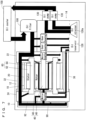
Fig. 5 is an illustrative sectional view which shows the motor unit inFig. 1 . -
Fig. 6 is a plan view which shows a gasket. -
Fig. 7 is a schematic illustration which shows oil paths. - Hereinafter, embodiments of the present invention will be described with reference to the drawings.
- A
motor unit 10 according to an embodiment of the present invention is suitably applied to an electric vehicle. The terms front and rear, left and right, and up and down used in the embodiments of the present invention are defined based on a direction in which a rotor 40 (which will be described later) extends as the left-right direction, and a direction from a motor 12 (which will be described later) toward an inverter 16 (which will be described later) as the rearward direction. In the drawings, "Fr" indicates forward, "Rr" indicates rearward, "R" indicates rightward, "L" indicates leftward, "U" indicates upward and "Lo" indicates downward. - Referring to
Fig. 1 through Fig. 4 , themotor unit 10 is a mechatronic integrated unit including themotor 12, aspeed reducer 14, and aninverter 16. Thespeed reducer 14 is provided on a side (left side in the present embodiment) of themotor 12, while theinverter 16 is provided behind themotor 12 and thespeed reducer 14. - Referring also to
Fig. 5 , themotor 12 includes acase 18. Thecase 18 has a three-tier structure, and includes astator housing 20, afirst motor cover 22 provided at an output side end portion of thestator housing 20, and asecond motor cover 24 provided at a non-output side end portion of thestator housing 20. Thesecond motor cover 24 includes a covermain body 26, and apipe holder 28 attached to the covermain body 26. A branchingpiece 30 is provided between the covermain body 26 and thepipe holder 28. - Outside the stator housing 20, there is provided a first externally attached
pipe 32 held by thefirst motor cover 22 and thesecond motor cover 24. The first externally attachedpipe 32 is a separate member from thestator housing 20, provided slightly spaced away from thestator housing 20, and sandwiched by thefirst motor cover 22 and thesecond motor cover 24. The first externally attachedpipe 32 has an outlet side end portion that is held by thepipe holder 28 and is connected with the branchingpiece 30. Inside the first externally attachedpipe 32, there is formed anoutward oil path 34 which provides communication between thefirst motor cover 22 and thesecond motor cover 24. Also, outside the stator housing 20 at a position lower than the first externally attachedpipe 32, there is provided a second externally attachedpipe 36 held by thefirst motor cover 22 and thesecond motor cover 24. The second externally attachedpipe 36 is a separate member from thestator housing 20, provided slightly spaced away from thestator housing 20, and sandwiched by thefirst motor cover 22 and thesecond motor cover 24. The second externally attachedpipe 36 has an inlet side end portion that is held by thepipe holder 28. Inside the second externally attachedpipe 36, there is formed areturn oil path 38 which provides communication between thefirst motor cover 22 and thesecond motor cover 24. Thereturn oil path 38 is provided at a lower position than theoutward oil path 34. Preferably, theoutward oil path 34 has a smaller sectional area than thereturn oil path 38. In other words, preferably, an inner diameter of the first externally attachedpipe 32 is smaller than that of the second externally attachedpipe 36. - The
rotor 40 is provided inside thecase 18. Therotor 40 is held rotatably by thefirst motor cover 22 and thesecond motor cover 24 viamotor bearings rotor 40 includes arotor shaft 46 and arotor core 48. Therotor shaft 46 has an axially extendinghollow portion 50. Therotor core 48 has a plurality of rotor core holes 52 and a plurality ofmagnets 54.End plates rotor core 48. - Inside the
case 18, astator 60 is provided radially outside therotor 40. Thestator 60 includes astator core 62 which is provided radially outside therotor 40 and is fixed to thestator housing 20, and astator coil 64 which is wound around thestator core 62. Thestator core 62 is fixed to thestator housing 20 by means of shrink fit. Coil end covers 66, 68 are provided to cover two axial end portions of thestator coil 64, i.e., to cover coil ends. - Between the
second motor cover 24 and therotor shaft 46, there is provided aresolver 70 for detection of a rotating angle of therotor shaft 46. Theresolver 70 includes aresolver stator 72 which is attached to thesecond motor cover 24, and aresolver rotor 74 which is attached to therotor shaft 46. Theresolver rotor 74 is fixed to a rear end portion of therotor shaft 46 with abolt 76 which has a generally hat-like section. - Referring to
Fig. 1 , thestator housing 20 and thefirst motor cover 22 are connected to each other by a plurality ofbolts 78. Eachbolt 78 is threaded into aboss 80 which is provided on an output side end portion in an outer circumferential surface of thestator housing 20 and aboss 82 which is provided on an outer circumferential portion of thefirst motor cover 22. Thestator housing 20 and thesecond motor cover 24 are connected to each other by a plurality ofbolts 84. Eachbolt 84 is threaded into aboss 86 which is provided on a non-output side end portion in an outer circumferential surface of thestator housing 20 and aboss 88 which is provided on an outer circumferential portion of thesecond motor cover 24. - Referring to
Fig. 5 , acover 90 is provided on a side of thesecond motor cover 24. Agasket 92 is placed between thesecond motor cover 24 and thecover 90. Referring toFig. 6 , thegasket 92 is formed in a generally annular shape, and has through-holes pipe 98 extending into thehollow portion 50 of therotor shaft 46 is attached at a center portion of thecover 90. - In an outer surface of the
first motor cover 22, anoil filter 100 is provided for filtration of oil which is to be supplied into thecase 18. Theoil filter 100 is supplied with oil from an oil cooler 158 (which will be described later) provided outside themotor unit 10. Theoil filter 100 has a generally cylindrical outer shape, having anoil discharge port 100a at a center of an end portion facing thefirst motor cover 22. Theoil filter 100 and thefirst motor cover 22 are connected with each other by aunion bolt 102. Theunion bolt 102 is attached to an inlet-side end portion of an oil path 134 (which will be described later) of thefirst motor cover 22, and is inserted into theoil discharge port 100a of theoil filter 100. - Referring also to
Fig. 3 , when viewed axially of therotor shaft 46, at least part of a lower half of theoil filter 100 overlaps with an upper half of thestator core 62. Theoil filter 100 is at a higher position than therotor shaft 46 and an output shaft 114 (which will be described later). A center C of theoil filter 100 is at a higher position than an outer circumferential surface of thestator coil 64. When viewed axially along therotor shaft 46, at least part of theoil filter 100 overlaps with the first externally attachedpipe 32. Preferably, if theoil filter 100 is provided by a cylindrical filter, theoil discharge port 100a is at the center of theoil filter 100, and the center of theoil filter 100 is at a position higher than theoutput shaft 114 and higher than therotor shaft 46. In this case, the layout of theoil filter 100 is compact, and it is possible to design the oil path appropriately. - The
speed reducer 14 is provided on a side (left side in the present embodiment) of thefirst motor cover 22 in order to slow down rotation of the rotor. Thespeed reducer 14 includes agear cover 104 provided on a side of thefirst motor cover 22. Referring toFig. 3 andFig. 5 , thegear cover 104 is provided therein with aninput gear 106, anintermediate shaft 108,intermediate gears output shaft 114, and anoutput gear 116. Theintermediate shaft 108 and theoutput shaft 114 are in parallel to therotor shaft 46. Theinput gear 106 is attached to a tip portion of therotor shaft 46, and is supported rotatably by thefirst motor cover 22 and thegear cover 104 viainput gear bearings intermediate shaft 108 is supported rotatably by thefirst motor cover 22 and thegear cover 104 viaintermediate gear bearings intermediate gears intermediate shaft 108. Theintermediate gear 110 meshes with theinput gear 106. Theintermediate gear 112 meshes with theoutput gear 116. Theoutput shaft 114 is supported rotatably by thefirst motor cover 22 and thegear cover 104 via unillustrated bearings. Theoutput gear 116 is attached to theoutput shaft 114. With a line segment connecting a center of therotor shaft 46 and a center of theoutput shaft 114 being called a reference line B; a perpendicular line perpendicular to the reference line B and passing the center of therotor shaft 46 being called a first perpendicular line V1; and a perpendicular line perpendicular to reference line B and passing the center of theoutput shaft 114 being called a second perpendicular line V2; when viewed axially along therotor shaft 46, at least part of theoil filter 100 overlaps with a region surrounded by the Reference line B, the first perpendicular line V1 and the second perpendicular line V2. Thegear cover 104 covers an outer surface of thefirst motor cover 22, whereby anoil reservoir 126 which communicates with thereturn oil path 38 is formed. In other words, theoil reservoir 126 is formed inside thespeed reducer 14. Theoil reservoir 126 is provided with anoil strainer 126a, and stores oil from thecase 18 and oil from thegear cover 104. - The
gear cover 104 is provided with two oil level gauges 128 for detecting an amount of oil inside theoil reservoir 126. Also, thegear cover 104 is provided with twooil pumps 130 for supplying oil from inside theoil reservoir 126 to theexternal oil cooler 158. In other words, the twooil pumps 130 are provided on an outer surface of thespeed reducer 14 in order to discharge oil to an outside. - The
inverter 16 is connected with a battery (not illustrated) via connectingterminals 132, converts a direct current from the battery into an alternating current, and supplies the current to themotor 12. - The
motor unit 10 described thus far is formed with oil paths as follows:
Referring toFig. 5 andFig. 7 , thefirst motor cover 22 has anoil path 134 communicating with theoutward oil path 34 to supply oil from theoil filter 100 to theoutward oil path 34, andoil paths oil path 134. Theoil path 134 provides communication between theoil discharge port 100a of theoil filter 100 and theoutward oil path 34 of the first externally attachedpipe 32. Theoil path 136 communicates with anoil path 142 inside thespeed reducer 14, to supply oil to theinput gear bearing 120. Oil from theoil path 138 is supplied to themotor bearing 42 and theinput gear bearing 118. Oil from theoil path 140 is supplied to the coil end of thestator coil 64. As described, oil is supplied into thecase 18 via theoil paths oil path 134 flows through theoutward oil path 34 and is supplied to thesecond motor cover 24. - The
second motor cover 24 hasoil paths outward oil path 34 and is supplied to thesecond motor cover 24 is divided by the branchingpiece 30, supplied to the coil end of thestator coil 64 via theoil path 144, and sent toward thecover 90 via theoil path 146. Thecover 90 has anoil path 150. Theoil path 150 is capable of communicating theoil paths oil path 146 and theoil path 150 communicate with each other via the through-hole 94 of thegasket 92, while theoil path 150 and theoil path 148 communicate with each other via the through-hole 96 of thegasket 92. Therefore, theoil paths second motor cover 24 communicate with each other via theoil path 150 of thecover 90, and oil from theoil path 146 is supplied to themotor bearing 44 and its surroundings via theoil paths oil path 150 communicates, via thepipe 98, thehollow portion 50 of therotor shaft 46 and the rotor core holes 52, with anoil path 152 which leads to the coil end of thestator coil 64. Therefore, oil from theoil path 150 is supplied to the coil end of thestator coil 64 via theoil path 152. As described, oil from theoutward oil path 34 is supplied into thecase 18 via thesecond motor cover 24 and thecover 90. - Oil which is supplied to the coil end of the
stator coil 64 is then supplied to theoil reservoir 126 via anoil path 154 and thereturn oil path 38, or via anoil path 156 of thefirst motor cover 22. Oil inside theoil reservoir 126 is sucked by the twooil pumps 130 through theoil strainer 126a, and supplied to theoil cooler 158. Theoil cooler 158 cools the oil, and then the oil is returned to theoil filter 100. - In the present embodiment, the first externally attached 32 represents the externally attached pipe.
- According to the
motor unit 10 as described thus far, theoil filter 100 is provided on the outer surface of thefirst motor cover 22 so that at least part of the lower half of theoil filter 100 overlaps with the upper half of thestator core 62 when viewed axially along therotor shaft 46. This makes it possible to provide theoil filter 100 on thefirst motor cover 22, at a higher position than the center, i.e., above the center, of thestator core 62, by utilizing an empty space that does not interfere with other members. Therefore, it is possible to configure themotor unit 10 compactly. - The oil pumps 130 for discharging oil out of the
oil reservoir 126 of thespeed reducer 14 is provided on the outer surface of thespeed reducer 14. Therefore, it is possible to configure themotor unit 10 compactly, including the oil pumps 130. - The region surrounded by the reference line B, the first perpendicular line V1 and the second perpendicular line V2 when viewed axially along the
rotor shaft 46 is often left as an empty space. Therefore, by providing theoil filter 100 in such a way that at least part of theoil filter 100 overlaps with the region, it becomes possible to make an effective use of the empty space without interfering with other members, and to configure themotor unit 10 compactly. - Since the
oil filter 100 is at a higher position than theoutput shaft 114, it is possible to configure themotor unit 10 compactly without interfering with output from theoutput shaft 114 of thespeed reducer 14. - Since the
oil filter 100 is at a higher position than therotor shaft 46, it is possible to configure themotor unit 10 compactly without interfering with output from therotor shaft 46 of therotor 40. - Since the center C of the
oil filter 100 is at a higher position than the outer circumferential surface of thestator coil 64, it is possible to drop oil easily onto thestator coil 62 inside thecase 18 via theoil filter 100. - The region outside the
stator housing 20 where the first externally attachedpipe 32 is provided, and a region adjacent thereto are often left as empty spaces. Therefore, by providing theoil filter 100 in such a way that at least part of theoil filter 100 overlaps with the first externally attachedpipe 32 when viewed axially along therotor shaft 46, it becomes possible to make an effective use of the empty space without interfering with other member, and to configure themotor unit 10 compactly. - It is possible to supply oil smoothly to the
outward oil path 34 of the first externally attachedpipe 32 from theoil discharge port 100a provided at the end portion of theoil filter 100 which faces thefirst motor cover 22, via theoil path 134 of thefirst motor cover 22. - The present invention being thus far described in terms of preferred embodiments, it is obvious that these may be varied in many ways within the scope and the spirit of the present invention. The scope of the present invention is only limited by the accompanied claims.
-
- 10 Motor unit
- 12 Motor
- 14 Speed reducer
- 16 Inverter
- 18 Case
- 20 Stator housing
- 22 First motor cover
- 24 Second motor cover
- 32 First externally attached pipe
- 34 Outward oil path
- 36 Second externally attached pipe
- 38 Return oil path
- 40 Rotor
- 46 Rotor shaft
- 48 Rotor core
- 60 Stator
- 62 Stator core
- 64 Stator coil
- 90 Cover
- 92 Gasket
- 100 Oil filter
- 100a Oil discharge port
- 108 Intermediate shaft
- 114 Output shaft
- 126 Oil reservoir
- 130 Oil pump
- 134, 136, 138, 140, 142, 144, 146, 148, 150, 152, 154, 156 Oil paths
- B Reference line
- C Center of oil filter
- V1 First perpendicular line
- V2 Second perpendicular line
Claims (8)
- A motor unit comprising:a case including a stator housing, a first motor cover provided at an output side end portion of the stator housing, and a second motor cover provided at a non-output side end portion of the stator housing;a rotor provided inside the case and having a rotor shaft;a stator provided inside the case and having a stator core provided radially outside the rotor and a stator coil provided in the stator core; andan oil filter provided on an outer surface of the first motor cover for filtration of oil to be supplied into the case; whereinat least part of a lower half of the oil filter overlaps with an upper half of the stator core when viewed axially along the rotor shaft.
- The motor unit according to Claim 1, further comprising a speed reducer provided on a side of the first motor cover in order to slow down rotation of the rotor and including an oil reservoir storing oil from the case, and
an oil pump provided on an outer surface of the speed reducer in order to discharge oil out of the oil reservoir. - The motor unit according to Claim 2, whereinthe speed reducer further includes an output shaft provided in parallel with the rotor shaft; andwith a line segment connecting a center of the rotor shaft and a center of the output shaft being called a reference line, a perpendicular line perpendicular to the reference line and passing the center of the rotor shaft being called a first perpendicular line, and a perpendicular line perpendicular to the reference line and passing the center of the output shaft being called a second perpendicular line;at least part of the oil filter overlaps with a region surrounded by the reference line, the first perpendicular line and the second perpendicular line when viewed axially along the rotor shaft.
- The motor unit according to Claim 3, wherein the oil filter is at a higher position than the output shaft.
- The motor unit according to one of Claims 1 through 4, wherein the oil filter is at a higher position than the rotor shaft.
- The motor unit according to one of Claims 1 through 5, wherein a center of the oil filter is at a higher position than an outer circumferential surface of the stator coil.
- The motor unit according to one of Claims 1 through 6, further comprising an externally attached pipe provided outside the stator housing, having an outward oil path for supplying oil which has passed the oil filter into the case, and held by the first motor cover and the second motor cover; wherein
at least part of the oil filter overlaps with the externally attached pipe when viewed axially along the rotor shaft. - The motor unit according to Claim 7, whereinthe oil filter has an oil discharge port at an end portion facing the first motor cover, andthe first motor cover has an oil path for communication between the oil discharge port and the outward oil path of the externally attached pipe.
Applications Claiming Priority (2)
| Application Number | Priority Date | Filing Date | Title |
|---|---|---|---|
| JP2021102790 | 2021-06-21 | ||
| PCT/JP2022/014120 WO2022270089A1 (en) | 2021-06-21 | 2022-03-24 | Motor unit |
Publications (2)
| Publication Number | Publication Date |
|---|---|
| EP4362291A1 true EP4362291A1 (en) | 2024-05-01 |
| EP4362291A4 EP4362291A4 (en) | 2025-06-25 |
Family
ID=84544633
Family Applications (1)
| Application Number | Title | Priority Date | Filing Date |
|---|---|---|---|
| EP22828008.7A Withdrawn EP4362291A4 (en) | 2021-06-21 | 2022-03-24 | ENGINE UNIT |
Country Status (4)
| Country | Link |
|---|---|
| US (1) | US20240154501A1 (en) |
| EP (1) | EP4362291A4 (en) |
| JP (1) | JP7649853B2 (en) |
| WO (1) | WO2022270089A1 (en) |
Families Citing this family (4)
| Publication number | Priority date | Publication date | Assignee | Title |
|---|---|---|---|---|
| DE102022134151A1 (en) * | 2022-12-20 | 2024-06-20 | Valeo Eautomotive Germany Gmbh | Electric machine, especially for driving a vehicle |
| CN117419149A (en) * | 2023-04-17 | 2024-01-19 | 宁德时代(上海)智能科技有限公司 | Electric drive assembly and electric equipment |
| DE102024201739A1 (en) * | 2024-02-26 | 2025-08-28 | Zf Friedrichshafen Ag | Oil guide arrangement for a drive unit |
| DE102024201738A1 (en) * | 2024-02-26 | 2025-08-28 | Zf Friedrichshafen Ag | Oil guide arrangement for a drive unit |
Family Cites Families (14)
| Publication number | Priority date | Publication date | Assignee | Title |
|---|---|---|---|---|
| JP5328231B2 (en) | 2008-06-12 | 2013-10-30 | 本田技研工業株式会社 | Vehicle drive motor unit |
| EP2537235B1 (en) * | 2010-02-19 | 2015-04-22 | Magna Powertrain AG & Co. KG | Electric drive unit |
| DE102010048131A1 (en) * | 2010-10-11 | 2012-04-12 | Magna Powertrain Ag & Co. Kg | Electrical drive unit for use as power source at axles in electrically or hybrid-electrically driven vehicle, has cooling circuit carrying coolant to cool stator and circuit, where coolant stays in heat exchanging connection to fluid |
| JP2014177899A (en) | 2013-03-14 | 2014-09-25 | Honda Motor Co Ltd | Power unit for vehicle |
| CN203384050U (en) | 2013-07-19 | 2014-01-08 | 浙江飞越机电有限公司 | Two-stage sliding-vane rotary vacuum pump with side-placed oil tank |
| JP2015027820A (en) | 2013-07-30 | 2015-02-12 | Ntn株式会社 | In-wheel motor driving device |
| JP2019154115A (en) | 2018-03-01 | 2019-09-12 | 本田技研工業株式会社 | Cooling system for rotary electric machine, and rotary electric machine with the same |
| US20190316588A1 (en) | 2018-04-16 | 2019-10-17 | Lincoln Global, Inc. | Multifunction engine-driven generator system |
| CN111585394B (en) * | 2019-02-15 | 2022-08-19 | 日本电产株式会社 | Motor unit |
| DE102019128957A1 (en) * | 2019-10-28 | 2021-04-29 | Audi Ag | Lubricant supply device for a motor vehicle, method for operating such a lubricant supply device and motor vehicle with such a lubricant supply device |
| CN114556752B (en) * | 2019-11-02 | 2024-07-12 | 博格华纳公司 | Drive module with improved efficiency |
| CN211791056U (en) | 2020-03-31 | 2020-10-27 | 六安华科电机有限公司 | Water-cooled motor cover |
| KR102726816B1 (en) * | 2020-10-05 | 2024-11-05 | 현대자동차주식회사 | Oil recovery structure for cooling motor |
| JP7533276B2 (en) * | 2021-02-25 | 2024-08-14 | ニデック株式会社 | Motor |
-
2022
- 2022-03-24 WO PCT/JP2022/014120 patent/WO2022270089A1/en not_active Ceased
- 2022-03-24 JP JP2023529594A patent/JP7649853B2/en active Active
- 2022-03-24 EP EP22828008.7A patent/EP4362291A4/en not_active Withdrawn
-
2023
- 2023-12-18 US US18/542,822 patent/US20240154501A1/en not_active Abandoned
Also Published As
| Publication number | Publication date |
|---|---|
| US20240154501A1 (en) | 2024-05-09 |
| WO2022270089A1 (en) | 2022-12-29 |
| JPWO2022270089A1 (en) | 2022-12-29 |
| EP4362291A4 (en) | 2025-06-25 |
| JP7649853B2 (en) | 2025-03-21 |
Similar Documents
| Publication | Publication Date | Title |
|---|---|---|
| US20240154501A1 (en) | Motor unit | |
| US11732795B2 (en) | Drive device | |
| JP7613542B2 (en) | Motor Unit | |
| CN114520563B (en) | Driving device and vehicle | |
| KR20190090347A (en) | Vehicle drive device | |
| EP2749737B1 (en) | Electric pump | |
| CN210327287U (en) | Motor and vehicle | |
| US20240120797A1 (en) | Motor and motor unit | |
| JP5146363B2 (en) | Electric motor | |
| CN111817499A (en) | Drive device | |
| CN107078606A (en) | Electric rotating machine | |
| CN112533783B (en) | Motor unit | |
| EP2863522A1 (en) | Rotating electrical machine | |
| CN115208130A (en) | Drive device and vehicle | |
| JP7092015B2 (en) | Lubrication structure of power transmission device | |
| US20240120798A1 (en) | Motor, motor unit, vehicle driving motor unit and electric vehicle | |
| JP7331430B2 (en) | drive | |
| JP2023066956A (en) | Drive device | |
| US12456899B2 (en) | Drive apparatus | |
| CN115720027A (en) | Drive device | |
| JP7452423B2 (en) | motor | |
| CN111835152B (en) | Driving device | |
| CN111033969A (en) | drive | |
| EP4535626A1 (en) | Motor and motor unit | |
| CN116373584A (en) | drive unit for vehicle |
Legal Events
| Date | Code | Title | Description |
|---|---|---|---|
| STAA | Information on the status of an ep patent application or granted ep patent |
Free format text: STATUS: THE INTERNATIONAL PUBLICATION HAS BEEN MADE |
|
| PUAI | Public reference made under article 153(3) epc to a published international application that has entered the european phase |
Free format text: ORIGINAL CODE: 0009012 |
|
| STAA | Information on the status of an ep patent application or granted ep patent |
Free format text: STATUS: REQUEST FOR EXAMINATION WAS MADE |
|
| 17P | Request for examination filed |
Effective date: 20240117 |
|
| AK | Designated contracting states |
Kind code of ref document: A1 Designated state(s): AL AT BE BG CH CY CZ DE DK EE ES FI FR GB GR HR HU IE IS IT LI LT LU LV MC MK MT NL NO PL PT RO RS SE SI SK SM TR |
|
| XX | Miscellaneous (additional remarks) |
Free format text: THE APPLICANT HAS FILED A TEXT WITH WHICH IT IS INTENDED TO BRING THE TRANSLATION INTO CONFORMITY WITH THE APPLICATION AS FILED (ART. 14(2) EPC). |
|
| DAV | Request for validation of the european patent (deleted) | ||
| DAX | Request for extension of the european patent (deleted) | ||
| A4 | Supplementary search report drawn up and despatched |
Effective date: 20250526 |
|
| RIC1 | Information provided on ipc code assigned before grant |
Ipc: H02K 9/193 20060101ALI20250520BHEP Ipc: H02K 7/116 20060101ALI20250520BHEP Ipc: H02K 5/20 20060101AFI20250520BHEP |
|
| STAA | Information on the status of an ep patent application or granted ep patent |
Free format text: STATUS: THE APPLICATION HAS BEEN WITHDRAWN |
|
| 18W | Application withdrawn |
Effective date: 20250812 |