EP4362244A1 - Fiber laser device - Google Patents
Fiber laser device Download PDFInfo
- Publication number
- EP4362244A1 EP4362244A1 EP22848915.9A EP22848915A EP4362244A1 EP 4362244 A1 EP4362244 A1 EP 4362244A1 EP 22848915 A EP22848915 A EP 22848915A EP 4362244 A1 EP4362244 A1 EP 4362244A1
- Authority
- EP
- European Patent Office
- Prior art keywords
- fiber
- housing
- orientation
- laser device
- optical element
- Prior art date
- Legal status (The legal status is an assumption and is not a legal conclusion. Google has not performed a legal analysis and makes no representation as to the accuracy of the status listed.)
- Pending
Links
Images













Classifications
-
- H—ELECTRICITY
- H01—ELECTRIC ELEMENTS
- H01S—DEVICES USING THE PROCESS OF LIGHT AMPLIFICATION BY STIMULATED EMISSION OF RADIATION [LASER] TO AMPLIFY OR GENERATE LIGHT; DEVICES USING STIMULATED EMISSION OF ELECTROMAGNETIC RADIATION IN WAVE RANGES OTHER THAN OPTICAL
- H01S3/00—Lasers, i.e. devices using stimulated emission of electromagnetic radiation in the infrared, visible or ultraviolet wave range
- H01S3/05—Construction or shape of optical resonators; Accommodation of active medium therein; Shape of active medium
- H01S3/06—Construction or shape of active medium
- H01S3/063—Waveguide lasers, i.e. whereby the dimensions of the waveguide are of the order of the light wavelength
- H01S3/067—Fibre lasers
- H01S3/06704—Housings; Packages
-
- H—ELECTRICITY
- H01—ELECTRIC ELEMENTS
- H01S—DEVICES USING THE PROCESS OF LIGHT AMPLIFICATION BY STIMULATED EMISSION OF RADIATION [LASER] TO AMPLIFY OR GENERATE LIGHT; DEVICES USING STIMULATED EMISSION OF ELECTROMAGNETIC RADIATION IN WAVE RANGES OTHER THAN OPTICAL
- H01S3/00—Lasers, i.e. devices using stimulated emission of electromagnetic radiation in the infrared, visible or ultraviolet wave range
- H01S3/05—Construction or shape of optical resonators; Accommodation of active medium therein; Shape of active medium
- H01S3/06—Construction or shape of active medium
- H01S3/063—Waveguide lasers, i.e. whereby the dimensions of the waveguide are of the order of the light wavelength
- H01S3/067—Fibre lasers
- H01S3/06791—Fibre ring lasers
-
- H—ELECTRICITY
- H01—ELECTRIC ELEMENTS
- H01S—DEVICES USING THE PROCESS OF LIGHT AMPLIFICATION BY STIMULATED EMISSION OF RADIATION [LASER] TO AMPLIFY OR GENERATE LIGHT; DEVICES USING STIMULATED EMISSION OF ELECTROMAGNETIC RADIATION IN WAVE RANGES OTHER THAN OPTICAL
- H01S3/00—Lasers, i.e. devices using stimulated emission of electromagnetic radiation in the infrared, visible or ultraviolet wave range
- H01S3/09—Processes or apparatus for excitation, e.g. pumping
- H01S3/091—Processes or apparatus for excitation, e.g. pumping using optical pumping
- H01S3/094—Processes or apparatus for excitation, e.g. pumping using optical pumping by coherent light
- H01S3/094003—Processes or apparatus for excitation, e.g. pumping using optical pumping by coherent light the pumped medium being a fibre
-
- H—ELECTRICITY
- H01—ELECTRIC ELEMENTS
- H01S—DEVICES USING THE PROCESS OF LIGHT AMPLIFICATION BY STIMULATED EMISSION OF RADIATION [LASER] TO AMPLIFY OR GENERATE LIGHT; DEVICES USING STIMULATED EMISSION OF ELECTROMAGNETIC RADIATION IN WAVE RANGES OTHER THAN OPTICAL
- H01S3/00—Lasers, i.e. devices using stimulated emission of electromagnetic radiation in the infrared, visible or ultraviolet wave range
- H01S3/10—Controlling the intensity, frequency, phase, polarisation or direction of the emitted radiation, e.g. switching, gating, modulating or demodulating
- H01S3/11—Mode locking; Q-switching; Other giant-pulse techniques, e.g. cavity dumping
- H01S3/1106—Mode locking
- H01S3/1112—Passive mode locking
- H01S3/1115—Passive mode locking using intracavity saturable absorbers
- H01S3/1118—Semiconductor saturable absorbers, e.g. semiconductor saturable absorber mirrors [SESAMs]; Solid-state saturable absorbers, e.g. carbon nanotube [CNT] based
-
- H—ELECTRICITY
- H01—ELECTRIC ELEMENTS
- H01S—DEVICES USING THE PROCESS OF LIGHT AMPLIFICATION BY STIMULATED EMISSION OF RADIATION [LASER] TO AMPLIFY OR GENERATE LIGHT; DEVICES USING STIMULATED EMISSION OF ELECTROMAGNETIC RADIATION IN WAVE RANGES OTHER THAN OPTICAL
- H01S3/00—Lasers, i.e. devices using stimulated emission of electromagnetic radiation in the infrared, visible or ultraviolet wave range
- H01S3/005—Optical devices external to the laser cavity, specially adapted for lasers, e.g. for homogenisation of the beam or for manipulating laser pulses, e.g. pulse shaping
- H01S3/0092—Nonlinear frequency conversion, e.g. second harmonic generation [SHG] or sum- or difference-frequency generation outside the laser cavity
-
- H—ELECTRICITY
- H01—ELECTRIC ELEMENTS
- H01S—DEVICES USING THE PROCESS OF LIGHT AMPLIFICATION BY STIMULATED EMISSION OF RADIATION [LASER] TO AMPLIFY OR GENERATE LIGHT; DEVICES USING STIMULATED EMISSION OF ELECTROMAGNETIC RADIATION IN WAVE RANGES OTHER THAN OPTICAL
- H01S3/00—Lasers, i.e. devices using stimulated emission of electromagnetic radiation in the infrared, visible or ultraviolet wave range
- H01S3/09—Processes or apparatus for excitation, e.g. pumping
- H01S3/091—Processes or apparatus for excitation, e.g. pumping using optical pumping
- H01S3/094—Processes or apparatus for excitation, e.g. pumping using optical pumping by coherent light
- H01S3/094049—Guiding of the pump light
- H01S3/094053—Fibre coupled pump, e.g. delivering pump light using a fibre or a fibre bundle
-
- H—ELECTRICITY
- H01—ELECTRIC ELEMENTS
- H01S—DEVICES USING THE PROCESS OF LIGHT AMPLIFICATION BY STIMULATED EMISSION OF RADIATION [LASER] TO AMPLIFY OR GENERATE LIGHT; DEVICES USING STIMULATED EMISSION OF ELECTROMAGNETIC RADIATION IN WAVE RANGES OTHER THAN OPTICAL
- H01S3/00—Lasers, i.e. devices using stimulated emission of electromagnetic radiation in the infrared, visible or ultraviolet wave range
- H01S3/09—Processes or apparatus for excitation, e.g. pumping
- H01S3/091—Processes or apparatus for excitation, e.g. pumping using optical pumping
- H01S3/094—Processes or apparatus for excitation, e.g. pumping using optical pumping by coherent light
- H01S3/0941—Processes or apparatus for excitation, e.g. pumping using optical pumping by coherent light of a laser diode
-
- H—ELECTRICITY
- H01—ELECTRIC ELEMENTS
- H01S—DEVICES USING THE PROCESS OF LIGHT AMPLIFICATION BY STIMULATED EMISSION OF RADIATION [LASER] TO AMPLIFY OR GENERATE LIGHT; DEVICES USING STIMULATED EMISSION OF ELECTROMAGNETIC RADIATION IN WAVE RANGES OTHER THAN OPTICAL
- H01S3/00—Lasers, i.e. devices using stimulated emission of electromagnetic radiation in the infrared, visible or ultraviolet wave range
- H01S3/09—Processes or apparatus for excitation, e.g. pumping
- H01S3/091—Processes or apparatus for excitation, e.g. pumping using optical pumping
- H01S3/094—Processes or apparatus for excitation, e.g. pumping using optical pumping by coherent light
- H01S3/0941—Processes or apparatus for excitation, e.g. pumping using optical pumping by coherent light of a laser diode
- H01S3/09415—Processes or apparatus for excitation, e.g. pumping using optical pumping by coherent light of a laser diode the pumping beam being parallel to the lasing mode of the pumped medium, e.g. end-pumping
-
- H—ELECTRICITY
- H01—ELECTRIC ELEMENTS
- H01S—DEVICES USING THE PROCESS OF LIGHT AMPLIFICATION BY STIMULATED EMISSION OF RADIATION [LASER] TO AMPLIFY OR GENERATE LIGHT; DEVICES USING STIMULATED EMISSION OF ELECTROMAGNETIC RADIATION IN WAVE RANGES OTHER THAN OPTICAL
- H01S3/00—Lasers, i.e. devices using stimulated emission of electromagnetic radiation in the infrared, visible or ultraviolet wave range
- H01S3/14—Lasers, i.e. devices using stimulated emission of electromagnetic radiation in the infrared, visible or ultraviolet wave range characterised by the material used as the active medium
- H01S3/16—Solid materials
- H01S3/1601—Solid materials characterised by an active (lasing) ion
- H01S3/1603—Solid materials characterised by an active (lasing) ion rare earth
- H01S3/1608—Solid materials characterised by an active (lasing) ion rare earth erbium
Definitions
- the present disclosure relates to a fiber laser device.
- a device including a fiber structure (first optical element) including a saturable absorber and a wavelength division multiplexing coupler (second optical element) is known (for example, see Patent Literature 1).
- first fiber connector is provided at an end portion of a first fiber optically connected to the fiber structure
- second fiber connector is provided at an end portion of a second fiber optically connected to the wavelength division multiplexing coupler.
- the fiber structure and the wavelength division multiplexing coupler are optically connected via the first fiber connector and the second fiber connector.
- Patent Literature 1 Japanese Unexamined Patent Publication No. 2017-067804
- the first optical element and the second optical element are housed in a housing.
- the first optical element and the second optical element are housed in the housing as described above, there may be a problem that it is difficult to perform maintenance (observation, cleaning, and the like) on an end surface of the second fiber.
- an object of the present disclosure is to provide a fiber laser device capable of easily performing the maintenance on the end surface of the second fiber.
- a fiber laser device includes: a housing; a first optical element configured to be housed in the housing, include a first fiber and a first fiber connector provided at an end portion of the first fiber, and be for oscillating laser beam; a second optical element configured to be housed in the housing, include a second fiber and a second fiber connector provided at an end portion of the second fiber, and be for oscillating the laser beam; and a movable holder configured to hold the second fiber connector and be movable so that an orientation of the second fiber connector changes between a first orientation and a second orientation, the first optical element and the second optical element are optically connectable via the first fiber connector and the second fiber connector, a first opening is formed in a wall portion of the housing, the first orientation is an orientation of the second fiber connector when the first optical element and the second optical element are optically connected, and the second orientation is an orientation of the second fiber connector in which an end surface of the second fiber is exposed through the first opening.
- the end surface of the second fiber can be exposed through the first opening by moving the movable holder and setting the orientation of the second fiber connector, for example, from the first orientation to the second orientation.
- the end surface of the second fiber can be easily observed with a fiberscope, and the end surface of the second fiber can be easily cleaned with a cleaner. Therefore, the maintenance on the end surface of the second fiber can be easily performed.
- the movable holder may be provided on a support plate in the housing, and may be movable so that an orientation of the second fiber connector changes between the first orientation along the support plate and the second orientation perpendicular to the support plate.
- the movable holder is movable so that the orientation of the second fiber connector changes by 90°, and the orientation of the second fiber connector can be switched between the first orientation and the second orientation.
- the first opening may be formed in a wall portion facing or adjacent to the movable holder in the housing. In this case, the movable holder can be easily accessed through the first opening.
- the first optical element may include a saturable absorber, an excitation light source, or a wavelength division multiplexing coupler.
- the saturable absorber, the excitation light source or the wavelength division multiplexing coupler can be utilized as the first optical element.
- the first optical element may be detachably attached inside the housing.
- the maintenance on the end surface of the second fiber can be performed by removing the first optical element.
- the fiber laser device may further include a lock mechanism configured to prevent the first optical element from being removed from inside the housing when the laser beam is oscillated by the fiber laser device.
- a lock mechanism configured to prevent damage caused by removal of the first optical element at the time of oscillation of the laser beam.
- the first optical element may be housed in a module housing, a second opening may be formed in a wall portion of the housing, and the module housing may be detachably attached inside the housing through the second opening.
- the first optical element can be modularized, and the modularized first optical element can be attached and detached using the second opening of the housing.
- the module housing may be inserted through the second opening from one side in a predetermined direction of the module housing, the module housing may have a shape such that one side in a first direction perpendicular to the predetermined direction is different from the other side when viewed from the predetermined direction, and the second opening may correspond to the shape of the module housing. This makes it possible to prevent the module housing from being inserted through the second opening with one side and the other side in the first direction reversed.
- the fiber laser device may further include an elastic member configured to press the module housing toward a placement surface on which the module housing is placed.
- the elastic member can press the module housing against the placement surface.
- the fiber laser device may further include a grip portion provided on the module housing, the grip portion may be provided to project from an outer surface of the housing in a state where the module housing is attached inside the housing, and a projecting portion configured to cover at least a part of a periphery of the grip portion projecting may be provided on the outer surface of the housing.
- the grip portion is used (for example, gripped and moved) in a state where the module housing is attached inside the housing, there is a possibility that the module housing is displaced.
- it is difficult to grip the grip portion by the projecting portion, and use of the grip portion can be suppressed. This makes it possible to prevent positional displacement of the module housing.
- an end surface of the second fiber may be located outside the housing through the first opening. In this case, the maintenance on the end surface of the second fiber can be further easily performed.
- the movable holder may be at least partially formed of a magnetic material, a holding portion provided in the housing and formed of a magnetic material may be further provided, and when the movable holder is moved so that the orientation of the second fiber connector is the second orientation, the movable holder may be held to maintain the second orientation by magnetic force of the holding portion. In this case, it is possible to maintain a state in which the end surface of the second fiber is exposed through the first opening by using the magnetic force.
- the fiber laser device may further include a fiber tube fixed near the movable holder in the housing, and the second fiber may be inserted through the fiber tube.
- the second fiber is directly fixed near the movable holder, although vibration of the second fiber can be suppressed, the second fiber also tends to move greatly along with movement of the movable holder, and there is a possibility that the second fiber is bent due to the movement and performance is adversely affected.
- the vibration of the second fiber can be suppressed, and even when the second fiber moves along with the movable holder, the movement can be allowed, and bending of the second fiber can be suppressed.
- the movable holder may be movably fixed in the housing. Thus, position of the movable holder can be adjusted.
- the fiber laser device may include: a partition plate configured to partition an inside of the housing into a first space and a second space; and a fan configured to pump air in the first space, and the first optical element, the second optical element, and the movable holder may be arranged in the second space.
- a partition plate configured to partition an inside of the housing into a first space and a second space
- a fan configured to pump air in the first space, and the first optical element, the second optical element, and the movable holder may be arranged in the second space.
- the fiber laser device may further include: an adapter configured to connect the first fiber connector and the second fiber connector; and an adapter detector configured to detect presence or absence of the adapter.
- an adapter configured to connect the first fiber connector and the second fiber connector
- an adapter detector configured to detect presence or absence of the adapter.
- the first fiber connector and the second fiber connector can be reliably connected by the adapter. Further, based on a detection result of the adapter detector, it is possible to prevent forgetting to attach the adapter.
- the movable holder may include a fixing member fixed in the housing, and a swing member swingable about a swing shaft with respect to the fixing member and provided with the second fiber connector, and the swing member may be movable by a predetermined length in a direction along the swing shaft with respect to the fixing member.
- the first optical element and the second optical element are optically connected, even when the first fiber connector is shifted from the second fiber connector in the direction along the swing shaft, the second fiber connector can be moved so as to eliminate the shift.
- a supercontinuum light source 10 is a light source that generates supercontinuum light.
- the supercontinuum light source 10 constitutes a fiber laser device.
- the supercontinuum light source 10 is a broadband spectrum light source, and is used, for example, for biological observation and spectroscopic analysis.
- the supercontinuum light source 10 includes a laser oscillator 5, a fiber amplifier 20, a wavelength shift fiber 30, and a highly nonlinear optical fiber 50.
- the laser oscillator 5 is a ring-type laser oscillator. An output end of the laser oscillator 5 is connected to the fiber amplifier 20. An output end of the fiber amplifier 20 is connected to the wavelength shift fiber 30. An output end of the wavelength shift fiber 30 is connected to the highly nonlinear optical fiber 50.
- the highly nonlinear optical fiber 50 is a highly nonlinear optical fiber that generates supercontinuum light. The highly nonlinear optical fiber 50 expands a spectrum width of input pulse light by a nonlinear optical effect and converts the pulse light into the supercontinuum light. The supercontinuum light is output from an output end of the highly nonlinear optical fiber 50.
- such a supercontinuum light source 10 includes an excitation light source 11, a wavelength division multiplexing coupler 12, an amplification fiber 13, an output coupler 14, a fiber structure 15, and a housing 16.
- the excitation light source 11, the wavelength division multiplexing coupler 12, the amplification fiber 13, the output coupler 14, and the fiber structure 15 are housed in the housing 16.
- the excitation light source 11, the wavelength division multiplexing coupler 12, the amplification fiber 13, the output coupler 14, and the fiber structure 15 constitute an optical element for oscillating laser beam, and constitute the laser oscillator 5.
- the excitation light source 11 is, for example, a laser diode.
- the excitation light source 11 outputs excitation light.
- the excitation light source 11 has a fiber 21.
- the wavelength division multiplexing coupler 12 has a fiber 22 and a fiber 29.
- the wavelength division multiplexing coupler 12 reflects the excitation light input from the excitation light source 11 through the fiber 21 and outputs the excitation light to the fiber 22.
- the wavelength division multiplexing coupler 12 transmits the laser beam input from the fiber 28 of the fiber structure 15 through the fiber 29 and outputs the laser beam to the fiber 22.
- the fiber 29 constitutes a second fiber.
- the amplification fiber 13 absorbs the excitation light input through the fiber 22 and emits the laser beam.
- the amplification fiber 13 is, for example, an erbium-doped fiber (EDF) in which erbium (Er) is added to a core.
- EDF erbium-doped fiber
- the output coupler 14 includes a fiber 23, a fiber 24, and a fiber 26.
- the output coupler 14 divides the laser beam input from the amplification fiber 13 through the fiber 23 at a predetermined ratio, outputs a part of the laser beam to the fiber 26, and outputs the other part of the laser beam to the fiber 24.
- the laser light output to the fiber 24 is output to an outside as output light.
- the fiber 26 constitutes the second fiber.
- the fiber structure 15 is a structure including a saturable absorber K.
- the saturable absorber K is a material having light transparency changing depending on incident light intensity.
- the saturable absorber K includes a sheet-like resin material and a plurality of carbon nanotubes dispersed in the resin material.
- As the resin material a material having excellent heat resistance is used.
- the carbon nanotube absorbs light in a 1560 nm band, and has a saturable absorption characteristic in which the absorption decreases when the incident light intensity reaches a high level.
- the fiber structure 15 has fibers 27 and 28.
- the fibers 27 and 28 constitute a first fiber.
- distal end portions of the fibers 27 and 28 contact each other, and the saturable absorber K is disposed between the distal end portions of the fibers 27 and 28.
- the laser beam input from the fiber 26 of the output coupler 14 through the fiber 27 is incident on the saturable absorber K.
- the saturable absorber K absorbs incident light.
- the absorption of the saturable absorber K decreases, and the incident light transmits through the saturable absorber K.
- an amplitude of the oscillating laser beam temporally fluctuates at a high frequency due to a noise component, light at a high level of incident light intensity is transmitted without being absorbed by the saturable absorber K, and becomes the pulse light.
- the pulse light is superimposed on circulating continuous light, stimulated emission is promoted, the intensity increases, and the pulse light further easily transmits through the saturable absorber K.
- the pulse light While the pulse light circulates while growing in this manner, the pulse light is generated by the saturable absorption characteristic of the saturable absorber K, a fiber nonlinear effect, and a wavelength dispersion effect.
- the fiber structure 15 outputs the laser beam as the pulse light transmitted through the saturable absorber K to the fiber 29 through the fiber 28.
- the fiber structure 15 includes a first fiber connector 31A provided at an end portion of the fiber 27 and a first fiber connector 31B provided at an end portion of the fiber 28.
- the wavelength division multiplexing coupler 12 has a second fiber connector 32B provided at an end portion of the fiber 29.
- the output coupler 14 has a second fiber connector 32A provided at an end portion of the fiber 26.
- the first fiber connector 31A and the second fiber connector 32A can be connected via an adapter 79.
- the first fiber connector 31B and the second fiber connector 32B can be connected via an adapter 79.
- the fiber structure 15 constituting a first optical element and the output coupler 14 constituting a second optical element can be optically connected via the first fiber connector 31A and the second fiber connector 32A.
- the fiber 27 connected to the fiber structure 15 and the fiber 26 connected to the output coupler 14 can be optically connected.
- the fiber structure 15 constituting the first optical element and the wavelength division multiplexing coupler 12 constituting the second optical element can be optically connected via the first fiber connector 31B and the second fiber connector 32B.
- the fiber 28 connected to the fiber structure 15 and the fiber 29 connected to the wavelength division multiplexing coupler 12 can be optically connected.
- the fiber structure 15 is housed in a module housing 61 and modularized as a fiber module 60 for the fiber laser device.
- the fiber module 60 (module housing 61) for the fiber laser device is configured to be detachable from the supercontinuum light source 10.
- the "module” means, for example, one or a plurality of elements (parts and devices) grouped together in terms of function or configuration.
- a “front-rear direction” (“front” and “rear”) is for convenience based on an illustrated direction.
- An “up-down direction” (“up” and “down”) is a direction perpendicular to the front-rear direction, and is for convenience based on the illustrated direction.
- a direction perpendicular to both the front-rear direction and the up-down direction is also referred to as a "width direction ".
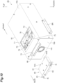
- the housing 16 has a rectangular box shape elongated in the front-rear direction.
- a bracket BR for mounting the supercontinuum light source 10 is fixed to a lower portion of a side wall of the housing 16.
- a first opening 71 is formed in an upper wall 16a of the housing 16.
- the upper wall 16a is a wall portion facing and adjacent to a movable holder 76 described later in the housing 16.
- the first opening 71 is formed at a position close to rear from a center in the front-rear direction of the upper wall 16a of the housing 16.
- the first opening 71 penetrates the housing 16 in the up-down direction so as to communicate an inside and an outside of the housing.
- the first opening 71 has a rectangular shape.
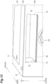
- a cover C0 (see FIG 12 ) is detachably attached to the first opening 71 so as to close the first opening 71.
- the first opening 71 is closed by the cover C0.
- a second opening (an opening) 72 is formed in a rear wall (a wall portion) 16b of the housing 16.
- the second opening 72 is formed in an upper portion of the rear wall 16b of the housing 16.
- the second opening 72 penetrates the housing 16 in the front-rear direction so as to communicate the inside and the outside of the housing.
- the second opening 72 has a rectangular shape elongated in the width direction.
- the second opening 72 constitutes an attachment port through which the fiber module 60 for the fiber laser device is inserted in the housing 16.
- the supercontinuum light source 10 includes a first partition plate (partition plate) 73, a second partition plate (support plate) 74, a fan 75, the movable holder 76, a holding portion 78, and an adapter 79 in the housing 16.
- the first partition plate 73 is a plate-like member that partitions an inside of the housing 16 vertically, and is fixed to the housing 16 with a screw or the like.
- the first partition plate 73 partitions the inside of the housing 16 into a first space R1 on the lower side and a second space R2 above the first space R1.
- the second partition plate 74 is a plate-like member that partitions the second space R2 in the housing 16 vertically, and is fixed to the housing 16 with a screw or the like.
- the second partition plate 74 partitions the second space R2 into a lower second space R21 on the lower side and an upper second space R22 above the lower second space R21.
- the fan 75 pumps air in the first space R1.
- the fan 75 is fixed to a rear portion of the first space R1 in the housing 16.
- the fan 75 pumps the air sucked into an intake port H0 from the outside to the front.
- an axial fan is used as the fan 75.
- the movable holder 76 is disposed in the housing 16.
- the movable holder 76 is provided on the second partition plate 74 (in the upper second space R22) in the housing 16.
- the movable holder 76 holds the second fiber connectors 32A and 32B and is movable so that orientations of the second fiber connectors 32A and 32B change between a first orientation and a second orientation.
- the orientations of the fiber connectors 32A and 32B correspond to, for example, optical axis directions of the end portions of the fibers 29 and 26 on which the fiber connectors 32A and 32B are provided.
- the movable holder 76 can be manually operated, for example, by a user.
- the first orientation is a orientation of the second fiber connectors 32A and 32B when the fiber structure 15, the wavelength division multiplexing coupler 12, and the output coupler 14 are optically connected to each other (that is, in a state where the fiber module 60 for the fiber laser device is attached.).
- the first orientation is a orientation along the second partition plate 74.
- the first orientation is rearward.
- the second orientation is a orientation of the second fiber connectors 32A and 32B that expose end surfaces of the fibers 29 and 26 through the first opening 71.
- the second orientation is a orientation perpendicular to the second partition plate 74.
- the second orientation is upward.
- Being exposed through the first opening 71 means, for example, appearing from the first opening 71, being visible from the first opening 71, and being exposed from the first opening 71.
- the movable holder 76 moves so that the orientation of the second fiber connectors 32A and 32B are the second orientation, the end surfaces of the fibers 29 and 26 are projected outward from the first opening 71, and the end surfaces of the fibers 29 and 26 are located outside the housing 16 through the first opening 71.
- the movable holder 76 includes a fixing member 81 fixed on the second partition plate 74 in the housing 16 (see FIG 4 ), and a swing member 82 connected to the fixing member 81 via a hinge 83.
- the hinge 83 one hinge plate side is swingable relative to the other hinge plate side about a swing shaft 83x along the width direction.
- a structure of the hinge 83 here is a looseness free (minimized) structure.
- the fixing member 81 is a plate-like member.
- the fixing member 81 has a thickness direction in the up-down direction and extends in the width direction.
- a long hole 81a elongated in the front-rear direction is formed in the fixing member 81.
- the fixing member 81 is fixed to the second partition plate 74 with a screw through the long hole 81a. That is, the fixing member 81 is fixed movable in the front-rear direction in the housing 16.
- One hinge plate sides of hinges 83 are attached to both end portions in the width direction of the fixing member 81.
- the swing member 82 is a member swingable with respect to the fixing member 81 about the swing shaft 83x of the hinge 83.
- the swing member 82 is provided with the second fiber connectors 32A and 32B.
- the swing member 82 includes a base plate 84, a pair of connector attachment portions 85, and a magnetic plate 86.
- the base plate 84 is a bent plate-like member, and includes a bottom plate 84x, a side plate 84y, and an upper plate 84z.
- a pair of the bottom plates 84x is provided and has a flat plate shape.
- the other hinge plate side of the hinge 83 is attached to the bottom plate 84x.
- the side plate 84y is provided perpendicular to the bottom plate 84x.
- the side plate 84y has a dimension corresponding to the fixing member 81 in the width direction.
- a pair of rectangular holes 84h through which the second fiber connectors 32A and 32B are inserted is formed apart from each other in the width direction.
- a pair of slits 84s through which an attachment plate 88 to be described later is inserted is formed apart from each other in the width direction.
- the rectangular hole 84h and the slit 84s communicate with each other.
- the upper plate 84z is provided perpendicular to the side plate 84y and has a flat plate shape.
- the magnetic plate 86 is fixed to the upper plate 84z.
- the connector attachment portion 85 includes a main body portion 87 and an attachment plate 88.
- the main body portion 87 has a block-shaped outer shape.
- the main body portion 87 is fixed to the side plate 84y of the base plate 84 with a screw.
- a recess 87x into which the second fiber connector 32A is fitted is formed in the main body portion 87.
- the recess 87x communicates with the rectangular hole 84h of the side plate 84y.
- a groove 87y through which the fiber 29 is inserted is formed in the main body portion 87.
- the groove 87y communicates with the recess 87x.
- the attachment plate 88 is fixed to the main body portion 87 with a screw so as to close the recess 87x and the groove 87y.
- the magnetic plate 86 is fixed to the upper plate 84z of the base plate 84 with a screw.
- the magnetic plate 86 is formed of a magnetic material. That is, at least a part of the movable holder 76 is formed of the magnetic material.
- the magnetic plate 86 is a member connectable to the holding portion 78 by magnetic force.
- the magnetic plate 86 has a plate shape elongated in the width direction.
- the holding portion 78 is provided in the housing 16.
- the holding portion 78 is fixed on the second partition plate 74 via a stay ST.
- the holding portion 78 is formed of the magnetic material.
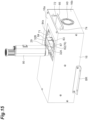
- the holding portion 78 can be connected to the magnetic plate 86 of the movable holder 76 by magnetic force (see FIG 13 ).
- the movable holder 76 is held to maintain the second orientation by the magnetic force of the holding portion 78.
- the adapter 79 is provided between the first fiber connector 31A and the second fiber connector 32A.
- the first fiber connector 31A is inserted and engaged in the adapter 79 and the second fiber connector 32A is inserted and engaged in the adapter 79 so that the first fiber connector 31A and the second fiber connector 32A (that is, the end portion of the fiber 27 and the end portion of the fiber 26) are optically connected.
- the adapter 79 is provided between the first fiber connector 31B and the second fiber connector 32B.
- the first fiber connector 31B is inserted and engaged in the adapter 79 and the second fiber connector 32B is inserted and engaged in the adapter 79 so that the first fiber connector 31B and the second fiber connector 32B (that is, the end portion of the fiber 28 and the end portion of the fiber 29) are optically connected.
- Fiber tubes 18 are provided near the movable holder 76 in the housing 16.
- the fiber tube 18 is a cylindrical member having flexibility.
- the fiber tube 18 is fixed onto the second partition plate 74 by a tape material 19.
- the fibers 26 and 29 are inserted through the fiber tubes 18.
- the fibers 26 and 29 are fixed onto the second partition plate 74 via the fiber tubes 18 near the movable holder 76.
- the tape material 19 for example, a polyimide tape is used.
- the supercontinuum light source 10 of the present embodiment includes the fiber module 60 for the fiber laser device in which the fiber structure 15 is modularized.
- the fiber module 60 for the fiber laser device includes the module housing 61, the fiber structure 15, and a grip portion 62.
- the module housing 61 has a rectangular box shape.
- the module housing 61 houses the fiber structure 15.
- the fiber structure 15 is disposed in a center portion of the module housing 61.
- a connector holding portion 64 is provided on one end side in the module housing 61.
- the connector holding portion 64 holds the first fiber connectors 31A and 31B such that the first fiber connectors 31A and 31B and end portions of the fibers 27 and 28 project outward from the module housing 61.
- a rectangular plate-shaped back plate 63 is fixed to a rear surface of the module housing 61, and the grip portion 62 is provided on a rear surface of the back plate 63.
- the module housing 61 is detachably attached inside the housing 16 through the second opening 72.
- the module housing 61 is inserted through the second opening 72 from the front side (one side in a predetermined direction) of the module housing 61.
- the fibers 27 and 28 are fixed on the other end portion side (a side opposite to a side where the first fiber connectors 31A and 31B and the end portions of the fibers 27 and 28 project from the module housing 61) of the module housing 61.
- straight portions which are linearly extending portions of the fibers 27 and 28, are fixed on the other end portion side of the module housing 61.
- the fibers 27 and 28 are fixed at portions in contact with an inner surface of the module housing 61. Fixing of the fibers 27 and 28 is achieved by adhering a tape material 65.
- the tape material 65 for example, the polyimide tape is used.
- a plurality of portions of the fibers 27 and 28 away from each other are adhered to the inner surface of the module housing 61 by the tape material 65.
- the grip portion 62 is a portion gripped by the user.
- the grip portion 62 is provided to project from an outer surface of the rear wall 16b of the housing 16 in a state where the module housing 61 is attached inside the housing 16.
- the grip portion 62 is, for example, a U-shaped member as viewed in the up-down direction.
- the grip portion 62 is gripped by inserting a hand in the up-down direction.
- the grip portion 62 extends rearward from one end side in the width direction of the back plate 63, bends in the width direction and extends in the width direction, and then bends forward to reach the other end side in the width direction of the back plate 63.
- the grip portion 62 is gripped and the module housing 61 is inserted from the second opening 72 of the housing 16.
- the module housing 61 is placed on an upper surface (a placement surface) of the second partition plate 74, the module housing 61 is moved forward while a lower surface of the module housing 61 is slid on the upper surface of the second partition plate 74, and the back plate 63 is brought into contact with a rear surface of the housing 16.
- the first fiber connectors 31A and 31B are inserted into the adapter 79, the fiber structure 15 and the wavelength division multiplexing coupler 12 are optically connected via the first fiber connector 31A and the second fiber connector 32A, and the fiber structure 15 and the output coupler 14 are optically connected via the first fiber connector 31B and the second fiber connector 32B.
- the back plate 63 is attached to the housing 16 by a screw N.
- attachment of the module housing 61 is completed.
- the module housing 61 is removed from inside the housing 16, the screw N is removed, the grip portion 62 is gripped, and the module housing 61 is moved rearward while sliding the lower surface of the module housing 61 on the upper surface of the second partition plate 74.
- the first fiber connectors 31A and 31B are removed from the adapter 79, and optical connections between the fiber structure 15 and the wavelength division multiplexing coupler 12 and the output coupler 14 are released. Then, the module housing 61 is pulled out from the second opening 72. Thus, removal of the module housing 61 is completed.
- the module housing 61 has a shape in which an upper side (one side in the first direction) is different from a lower side (the other side in the first direction) when viewed from the front-rear direction (predetermined direction). Specifically, when viewed from the front-rear direction, the module housing 61 has a shape in which a dimension in the width direction of an upper end portion thereof is larger than that in the width direction of the other portion.
- the second opening 72 corresponds to the shape of the module housing 61.
- the second opening 72 has a shape in which an upper side is different from a lower side when viewed from the front-rear direction. Specifically, when viewed from the front-rear direction, the second opening 72 has a shape in which a dimension in the width direction of an upper end portion thereof is larger than that in the width direction of the other portion.
- a projecting portion 66 projecting rearward is provided at a lower portion of a side edge of the second opening 72.
- the projecting portion 66 has a plate shape whose thickness direction is the up-down direction.
- Such a projecting portion 66 covers at least a part of a periphery of the grip portion 62 projecting from the outer surface of the rear wall 16b of the housing 16.
- the projecting portion 66 constitutes an eave provided below the second opening 72. The projecting portion 66 closes the grip portion 62 from below and inhibits insertion of the hand into the grip portion 62 from the up-down direction.
- the supercontinuum light source 10 includes a module guide 91 and an elastic member 92.
- the module guide 91 is a member that guides forward and backward movement of the module housing 61 entering the housing 16 through the second opening 72.
- the module guide 91 is fixed to a rear end portion on the second partition plate 74.
- the module guide 91 is a gate-shaped member that forms a space along an outer shape of the module housing 61.
- the module guide 91 is a plate member bent to form an inverted U shape when viewed from the rear.
- the elastic member 92 is, for example, a leaf spring.
- the elastic member 92 presses an upper surface of the module housing 61 entering the housing 16 through the second opening 72 downward toward the upper surface of the second partition plate 74.
- a pair of the elastic members 92 is provided on the front side of an upper portion of the module guide 91 so as to be separated from each other in the width direction.
- the movable holder 76 is moved in a state where the module housing 61 is removed from inside the housing 16, to change the orientation of the second fiber connectors 32A and 32B from rearward to upward. Specifically, a rear side of the swing member 82 is lifted, and the swing member 82 is swung by 90° with respect to the fixing member 81 about the swing shaft 83x of the hinge 83. Thus, a state in which the second fiber connectors 32A and 32B extend in the front-rear direction is changed to a state in which the second fiber connectors 32A and 32B rise in the up-down direction.
- the end surfaces of the fibers 29 and 26 project outward from the first opening 71, and the end surfaces of the fibers 29 and 26 are located outside the housing 16 through the first opening 71.
- the magnetic plate 86 of the swing member 82 is connected to the holding portion 78 by magnetic force, and a state of the movable holder 76 is held in which the second fiber connectors 32A and 32B face upward.
- a fiberscope 95 is installed, the end surfaces of the fibers 29 and 26 are observed with the fiberscope 95, and for example, it is checked that there is no foreign matter or dirt on the end surfaces of the fibers 29 and 26. Further, as illustrated in FIG 16 , the end surfaces of the fibers 29 and 26 are cleaned by a cleaner 96.
- the movable holder 76 is moved to change the orientations of the second fiber connectors 32A and 32B from upward to rearward. Specifically, connection between the magnetic plate 86 and the holding portion 78 by magnetic force is released, the rear side of the swing member 82 is tilted backward, and the swing member 82 is swung by 90° with respect to the fixing member 81 about the swing shaft 83x of the hinge 83. Thus, the state in which the second fiber connectors 32A and 32B rise in the up-down direction is changed to the state in which the second fiber connectors 32A and 32B extend in the front-rear direction.
- the module housing 61 is attached to the housing 16, and the fiber structure 15, the wavelength division multiplexing coupler 12, and the output coupler 14 are optically connected via the first fiber connectors 31A and 31B and the second fiber connectors 32A and 32B. Thus, the maintenance is completed.
- the end surfaces of the fibers 29 and 26 can be exposed through the first opening 71 by moving the movable holder 76 and setting the orientation of the second fiber connectors 32A and 32B, for example, from the first orientation to the second orientation.
- the end surfaces of the fibers 29 and 26 can be easily observed with the fiberscope 95, and the end surfaces of the fibers 29 and 26 can be easily cleaned with the cleaner 96. Therefore, the maintenance on the end surfaces of the fibers 29 and 26 can be easily performed.
- the end surfaces of the fibers 29 and 26 can be accessed without drawing the fibers 29 and 26. It is possible to avoid problems such as disconnection caused by drawing the fibers 29 and 26.
- the movable holder 76 is movable so that the orientation of the second fiber connectors 32A and 32B changes between the first orientation along the second partition plate 74 and the second orientation perpendicular to the second partition plate 74.
- the orientation of the second fiber connectors 32A and 32B can be switched between the first orientation and the second orientation.
- the first opening 71 is formed in the upper wall 16a facing and adjacent to the movable holder 76 in the housing 16. In this case, the movable holder 76 can be easily accessed through the first opening 71.
- the fiber structure 15 constituting the first optical element includes the saturable absorber K. In this case, the saturable absorber K can be utilized as the first optical element.
- the fiber structure 15 including the saturable absorber K is modularized as the fiber module 60 for the fiber laser device and detachably attached inside the housing 16.
- the maintenance on the end surfaces of the fibers 26 and 29 can be performed by removing the fiber module 60 for the fiber laser device.
- the fiber structure 15 is housed in the module housing 61.
- the second opening 72 is formed in the rear wall 16b of the housing 16.
- the module housing 61 is detachably attached inside the housing 16 through the second opening 72.
- the fiber structure 15 can be modularized, and the modularized fiber structure 15 can be attached and detached using the second opening 72 of the housing 16.
- the module housing 61 is inserted through the second opening 72 from the front side.
- the module housing 61 has a shape in which an upper side is different from a lower side when viewed from the front-rear direction.
- the second opening 72 corresponds to the shape of the module housing 61 (the shape in which the upper side is different from the lower side when viewed from the front-rear direction).
- the supercontinuum light source 10 includes the elastic member 92 that presses the module housing 61 toward the upper surface of the second partition plate 74 on which the module housing 61 is placed.
- the elastic member 92 can press the module housing 61 against the upper surface of the second partition plate 74.
- the supercontinuum light source 10 includes the grip portion 62 provided in the module housing 61.
- the grip portion 62 is provided to project from an outer surface of the rear wall 16b of the housing 16 in a state where the module housing 61 is attached inside the housing 16.
- the projecting portion 66 that covers a lower portion of the grip portion 62 projecting is provided on the outer surface of the rear wall 16b of the housing 16.
- the grip portion 62 in the supercontinuum light source 10, in the state where the module housing 61 is attached inside the housing 16, the grip portion 62 can be hardly gripped by the projecting portion 66, and use of the grip portion 62 can be suppressed. This makes it possible to prevent positional displacement of the module housing 61.
- the end surfaces of the fibers 26 and 29 are located outside the housing 16 through the first opening 71. In this case, the maintenance on the end surfaces of the fibers 26 and 29 can be further easily performed.
- the movable holder 76 includes the magnetic plate 86 formed of the magnetic material.
- the holding portion 78 formed of the magnetic material is provided.
- the movable holder 76 is moved so that the orientation of the second fiber connectors 32A and 32B are the second orientation, the movable holder 76 is held to maintain the second orientation by the magnetic force of the holding portion 78. In this case, it is possible to maintain a state in which the end surfaces of the fibers 26 and 29 are exposed through the first opening 71 by using the magnetic force.
- the supercontinuum light source 10 includes the fiber tube 18 fixed near the movable holder 76 in the housing 16.
- the fibers 26 and 29 are inserted through the fiber tubes 18.
- the fibers 26 and 29 are directly fixed near the movable holder 76, although vibrations of the fibers 26 and 29 can be suppressed, the fibers 26 and 29 also tend to move greatly along with movement of the movable holder 76, and there is a possibility that the fibers 26 and 29 are bent due to the movement and performance is adversely affected (for example, mode lock may be affected).
- the vibrations of the fibers 26 and 29 can be suppressed, and even when the fibers 26 and 29 move along with the movement of the movable holder 76, the movement can be allowed, and bending of the fibers 26 and 29 can be suppressed.
- the movable holder 76 is fixed to the second partition plate 74 through the long hole 81a (see FIG 7 ), and is fixed movable in the front-rear direction in the housing 16.
- position of the movable holder 76 in the front-rear direction can be adjusted.
- the movable holder 76 may be movably fixed in a direction other than the front-back direction, and in this case, the position of the movable holder 76 in the direction other than the front-back direction can be adjusted.
- the supercontinuum light source 10 includes the first partition plate 73 that partitions the inside of the housing 16 into the first space R1 and the second space R2, and the fan 75 that pumps the air in the first space R1.
- the fiber structure 15, the wavelength division multiplexing coupler 12, and the output coupler 14 are arranged in the second space R2. In this case, it is possible to prevent dust or the like from adhering to configurations of the fiber structure 15, the wavelength division multiplexing coupler 12, and the output coupler 14 (for example, the end surfaces of the fibers 26 and 29, and the like) due to influence of the air pumped by the fan 75. It is possible to provide a separation structure in which a portion in which the configurations of the fiber structure 15, the wavelength division multiplexing coupler 12, and the output coupler 14 are arranged and an air-cooled portion by the fan 75 are separated.
- the supercontinuum light source 10 includes the adapters 79 that connect the first fiber connectors 31A and 31B and the second fiber connectors 32A and 32B.
- the first fiber connectors 31A and 31B and the second fiber connectors 32A and 32B can be reliably connected by the adapters 79.
- the fiber structure 15 constituting the first optical element can be modularized, and the modularized fiber structure 15 can be attached and detached using the second opening 72 of the housing 16. Therefore, the fiber structure 15 can be easily replaced.
- the fiber structure 15 (saturable absorber K) can be modularized and easily replaced.
- the fiber structure 15 includes the saturable absorber K.
- the saturable absorber K can be utilized as the first optical element. Since the saturable absorber K needs to be replaced due to the life, an effect of easily replacing the saturable absorber K is particularly effective.
- the fiber module 60 for the fiber laser device when the fiber structure 15 is optically connected to the wavelength division multiplexing coupler 12 and the output coupler 14 via the first fiber connectors 31A and 31B, for example, the first fiber connectors 31A and 31B move due to looseness of the first fiber connectors 31A and 31B, and the end portions of the fibers 27 and 28 also move according to movement of the first fiber connectors 31A and 31B, which may adversely affect the performance.
- the fiber module 60 for the fiber laser device since the fibers 27 and 28 are fixed to the module housing 61, movement of the fibers 27 and 28 can be suppressed.
- the fibers 27 and 28 are fixed on one end side (a side close to the first fiber connectors 31A and 31B) in the module housing 61, since fiber lengths are short from the end portions of the fibers 27 and 28 to fixed positions, the fibers 27 and 28 are likely to be greatly displaced by movement of the first fiber connectors 31A and 31B and the end portions of the fibers 27 and 28, and furthermore, the fibers 27 and 28 are likely to be bent, which may adversely affect the performance.
- the fiber lengths from the end portions of the fibers 27 and 28 to the fixed positions is long. Therefore, it is possible to suppress bending of the fibers 27 and 28 due to the movement of the first fiber connectors 31A and 31B and the end portions of the fibers 27 and 28. Therefore, it is possible to suppress an adverse effect on the performance.
- the straight portions which are linearly extending portions of the fibers 27 and 28, are fixed on the other end portion side in the module housing 61. In this case, the bending of the fibers 27 and 28 can be further suppressed.
- the supercontinuum light source 10 may include a pair of movable holders 180 instead of the movable holder 76 ( FIG 4 ), and may further include an adapter detector 140.
- the pair of movable holders 180 is provided corresponding to each of the second fiber connectors 32A and 32B.
- the pair of movable holders 180 are independently movable.
- One movable holder 180 holds the second fiber connector 32B and is movable so that the orientation of the second fiber connector 32B changes between the first orientation and the second orientation.
- the other movable holder 180 holds the second fiber connector 32A and is movable so that the orientation of the second fiber connector 32A changes between the first orientation and the second orientation.
- the one movable holder 180 includes a fixing member 181 and a swing member 185 connected to the fixing member 181 via the hinge 83.
- the fixing member 181 is fixed on the second partition plate 74.
- One hinge plate side of the hinge 83 is fixed to the fixing member 181.
- the swing member 185 is a member swingable with respect to the fixing member 81.
- the other hinge plate side of the hinge 83 is fixed to the swing member 185.
- the swing member 185 has a block-shaped outer shape.
- the swing member 185 holds the second fiber connector 32B.
- a magnetic plate 186 is fixed to an upper surface of the swing member 185.
- the magnetic plate 186 is configured similarly to the magnetic plate 86 (see FIG 7 ).
- the magnetic plate 186 can be connected to a holding portion 178 included in the fixing member 181 by magnetic force.
- the holding portion 178 is configured similarly to the holding portion 78 (see FIG 7 ).
- one hinge plate side and the other hinge plate side are movable by a predetermined length.
- the swing member 185 is configured to be movable by a predetermined length in a direction along the swing shaft 83x with respect to the fixing member 181.
- the predetermined length may be a length corresponding to looseness between one hinge plate side and the other hinge plate side of the hinge 83, and may be, for example, 1 to 2 mm. Since the other movable holder 180 has the same configuration as the one movable holder 180, description thereof will be omitted.
- the adapter detector 140 includes a hinge 141 and a tilting plate 142.
- the hinge 141 tilts the tilting plate 142 about a swing shaft 141x along the width direction.
- a hinge plate 141A side which is a fixed side of the hinge 141, is fixed on the second partition plate 74.
- a hinge plate 141B side which is a movable side of the hinge 141, is fixed to a flat plate portion 142x described later of the tilting plate 142.
- a force of pulling the hinge plate 141B side which is the movable side downward acts.
- the tilting plate 142 includes the flat plate portion 142x having a flat plate shape and a bent portion 142y continuous to a rear end of the flat plate portion 142x so as to project upward.
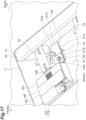
- an adapter detector 140 in such an adapter detector 140, as illustrated in FIG 18 , in a state where the movable holder 180 is moved so that the orientation of the second fiber connector 32A is the second orientation, the adapter 79 is separated from the bent portion 142y. At this time, the hinge plate 141A of the hinge 141 is pulled downward, the tilting plate 142 is tilted such that the front side is located downward with respect to the rear side, and the bent portion 142y rises. Then, as illustrated in FIG 17 , by moving the movable holder 180 so that the orientation of the second fiber connector 32A is the first orientation, the adapter 79 contacts the bent portion 142y, the bent portion 142y is pressed downward, and the tilting plate 142 maintains a state along a horizontal plane. The presence of the adapter 79 can be detected by detecting a state of the tilting plate 142.
- the tilting plate 142 maintains a tilted state.
- the presence of the adapter 79 can be detected by detecting a state of the tilting plate 142.
- the first fiber connector 31A of the fiber module 60 for the fiber laser device is brought into contact with the bent portion 142y, and the forward movement of the module housing 61 can be restricted so that the module housing 61 is not completely inserted forward.
- an interlock mechanism (not illustrated) is operated.
- the modification illustrated in FIGS. 17 , 18 , and 19 includes the adapter detector 140 that detects presence or absence of the adapter 79. In this case, based on a detection result of the adapter detector 140, it is possible to prevent forgetting to attach the adapter 79. In addition, when the adapter 79 is not mounted, the interlock mechanism can be operated. Thus, when the adapter 79 is not mounted, it is possible to prevent the laser beam from being emitted from the fiber module 60 for the fiber laser device. It is possible to prevent malfunction and to enhance safety when the adapter 79 is not mounted.
- the swing member 185 is movable by the predetermined length in the direction along the swing shaft 83x with respect to the fixing member 181.
- the fiber structure 15 is optically connected to the wavelength division multiplexing coupler 12 and the output coupler 14, even if the first fiber connectors 31A and 31B are shifted from the second fiber connectors 32A and 32B in the direction along the swing shaft 83x, the second fiber connectors 32A and 32B (the fiber module 60 for the fiber laser device) can be moved so as to eliminate the shift.
- the hinge 83 Since the hinge 83 has looseness, even if there is a positional shift between the first fiber connectors 31A and 31B and the second fiber connectors 32A and 32B, the first fiber connectors and the second fiber connectors can be fitted and inserted into the adapters 79.
- a supercontinuum light source 110 according to a second embodiment is different from the supercontinuum light source 10 (see FIG 2 ) according to the first embodiment in that the wavelength division multiplexing coupler 12 is modularized as a fiber module 160 for the fiber laser device.
- the wavelength division multiplexing coupler 12 includes fibers 121, 29, and 122, and fiber connectors 33A, 33B, and 33C provided at end portions of the fibers 121, 29, and 122.
- the excitation light source 11 includes the fiber 21 and a fiber connector 34A provided at an end portion of the fiber 21.
- the amplification fiber 13 includes the fiber 22 and a fiber connector 35C provided at an end portion of the fiber 22.
- the fiber connectors 34A and 33A can be connected to each other, the fiber connectors 31B and 33B can be connected to each other, and the fiber connectors 35C and 33C can be connected to each other.
- the wavelength division multiplexing coupler 12 constituting the first optical element and the fiber structure 15 constituting the second optical element can be optically connected via the fiber connectors and 33B and 31B. Further, the wavelength division multiplexing coupler 12 constituting the first optical element and the excitation light source 11 constituting the second optical element can be optically connected via the fiber connectors 33A and 34A. Further, the wavelength division multiplexing coupler 12 constituting the first optical element and the amplification fiber 13 constituting the second optical element can be optically connected via the fiber connectors 33C and 35C.
- the fiber connectors 33A, 33B, and 33C constitute the first fiber connector, and the fiber connectors 31B, 34A, and 35C constitute the second fiber connector.
- a supercontinuum light source 210 according to a third embodiment is different from the supercontinuum light source 10 (see FIG 2 ) according to the first embodiment in that the excitation light source 11 is modularized as a fiber module 260 for the fiber laser device.
- the excitation light source 11 includes the fiber 21 and the fiber connector 34A provided at the end portion of the fiber 21.
- the wavelength division multiplexing coupler 12 includes the fiber 121 and the fiber connector 33A provided at an end portion of the fiber 121.
- the fiber connectors 34A and 33A can be connected to each other. That is, the excitation light source 11 constituting the first optical element and the wavelength division multiplexing coupler 12 constituting the second optical element can be optically connected via the fiber connectors 34A and 33A.
- the fiber module 260 for the fiber laser device has a substrate 211 on which the excitation light source 11 is mounted.
- the fiber connector 34A constitutes the first fiber connector
- the fiber connector 33A constitutes the second fiber connector.
- one aspect of the present disclosure is not limited to the above embodiments, and may be modified within the scope not changing the gist described in each claim, or may be applied to other things.
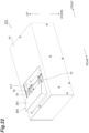
- a module housing 361 (a fiber module 360 for the fiber laser device) may be a supercontinuum light source 310 detachably attached to the housing 16 through a first opening 371.
- the module housing 361 corresponds to the module housing 61 (see FIG 10 ).
- First opening 371 corresponds to the first opening 71 (see FIG 10 ).
- the first opening 371 has a size that allows the module housing 61 to go out of the housing 16 through the first opening 371 without contacting the housing 16 when the movable holder 76 is moved. For example, in the front-rear direction, a length from a rear edge of the first opening 371 to the movable holder 76 is longer than that of the module housing 61 in the front-rear direction. Note that in the supercontinuum light source 310, the second opening 72 (see FIG 10 ) is not formed in the housing 16.
- the movable holder 76 is swung by 90° while the module housing 361 is attached, the module housing 361 projects from the first opening 371, and the second fiber connectors 32A and 32B face upward (the first fiber connectors 31A and 32A face downward). In this state, the module housing 361 can be removed from inside the housing 16 by removing the adapter 79.
- a fiber module 460 for the fiber laser device having an isolator 415 may be provided as illustrated in FIG 24 .
- the isolator 415 includes the saturable absorber K.
- the first optical element, the second optical element, and the optical element are not particularly limited, and may be various optical elements.
- the first opening 71 or 371 is formed in the upper wall 16a facing and adjacent to the movable holder 76 in the housing 16, but the first opening 71 or 371 may be formed in the wall portion facing or adjacent to the movable holder 76 in the housing 16.
- the module housing 61 has the shape in which the upper side is different from the lower side when viewed from the front-rear direction, but is not limited thereto, and one side in the width direction may have a shape different from the other side when viewed from the front-rear direction.
- the module housing 61 may have a shape in which one side in a first direction perpendicular to the front-rear direction is different from the other side when viewed from the front-rear direction.
- the projecting portion 66 that covers the lower portion of the grip portion 62 is provided on the outer surface of the housing 16, but the projecting portion 66 only needs to cover at least a part of the periphery of the grip portion 62 projecting.
- the first fiber connector 31A and the second fiber connector 32A are connected via the adapter 79, but the adapter 79 may be omitted in some cases.
- the end surfaces of the fibers 29 and 26 are projected outward from the first opening 71, and the end surfaces of the fibers 29 and 26 are located outside the housing 16 through the first opening 71, but the present invention is not limited thereto.
- the movable holder 76 moves so that the orientation of the second fiber connectors 32A and 32B are the second orientation, if the end surfaces of the fibers 29 and 26 are exposed from the first opening 71, the end surfaces of the fibers 29 and 26 may be located in the housing 16.
- the interlock mechanism may be operated to prevent the laser beam from being emitted from the fiber module 60 for the fiber laser device.
- the above embodiments may further include a lock mechanism that prevents the fiber module 60,160,260,360, or 460 (the first optical element) for the fiber laser device from being removed from inside the housing 16 when the laser beam is oscillated by the supercontinuum light source 10,110,210, or 310.
- a lock mechanism that prevents the fiber module 60,160,260,360, or 460 (the first optical element) for the fiber laser device from being removed from inside the housing 16 when the laser beam is oscillated by the supercontinuum light source 10,110,210, or 310.
- the lock mechanism is a safety mechanism that prevents the fiber module 60,160,260,360, or 460 for the fiber laser device from being removed when the supercontinuum light source 10,110,210, or 310 is operated (for example, when power is on).
- the lock mechanism may be a mechanism using a solenoid, and may be a detachment prevention pin that appears when the supercontinuum light source 10, 110, 210, or 310 is operated and engages with the module housing 61 or 361, and that is buried and releases the engagement when the supercontinuum light source 10, 110, 210, or 310 is not operated.
- the second fiber connectors 32Aand 32B may be held by a normal holder that is not movable instead of the movable holder 76.
- the first optical element is housed in the module housing 61 or 361 to be modularized as the fiber module 60,160,260,360, or 460 for the fiber laser device, but such modularization may not be performed in some cases.
- each configuration in the above-described embodiments and modifications can be arbitrarily applied to each configuration in other embodiments or modifications.
- One aspect of the present disclosure can also be regarded as the supercontinuum light source.
Landscapes
- Physics & Mathematics (AREA)
- Electromagnetism (AREA)
- Engineering & Computer Science (AREA)
- Plasma & Fusion (AREA)
- Optics & Photonics (AREA)
- Chemical & Material Sciences (AREA)
- Materials Engineering (AREA)
- Nanotechnology (AREA)
- Microelectronics & Electronic Packaging (AREA)
- Optical Couplings Of Light Guides (AREA)
- Optical Modulation, Optical Deflection, Nonlinear Optics, Optical Demodulation, Optical Logic Elements (AREA)
- Lasers (AREA)
Abstract
Description
- The present disclosure relates to a fiber laser device.
- As a technique related to a fiber laser device, a device including a fiber structure (first optical element) including a saturable absorber and a wavelength division multiplexing coupler (second optical element) is known (for example, see Patent Literature 1). In such a fiber laser device, a first fiber connector is provided at an end portion of a first fiber optically connected to the fiber structure, and a second fiber connector is provided at an end portion of a second fiber optically connected to the wavelength division multiplexing coupler. The fiber structure and the wavelength division multiplexing coupler are optically connected via the first fiber connector and the second fiber connector.
- Patent Literature 1:
Japanese Unexamined Patent Publication No. 2017-067804 - In the fiber laser device as described above, usually, the first optical element and the second optical element are housed in a housing. When the first optical element and the second optical element are housed in the housing as described above, there may be a problem that it is difficult to perform maintenance (observation, cleaning, and the like) on an end surface of the second fiber.
- Therefore, an object of the present disclosure is to provide a fiber laser device capable of easily performing the maintenance on the end surface of the second fiber.
- A fiber laser device according to one aspect of the present disclosure includes: a housing; a first optical element configured to be housed in the housing, include a first fiber and a first fiber connector provided at an end portion of the first fiber, and be for oscillating laser beam; a second optical element configured to be housed in the housing, include a second fiber and a second fiber connector provided at an end portion of the second fiber, and be for oscillating the laser beam; and a movable holder configured to hold the second fiber connector and be movable so that an orientation of the second fiber connector changes between a first orientation and a second orientation, the first optical element and the second optical element are optically connectable via the first fiber connector and the second fiber connector, a first opening is formed in a wall portion of the housing, the first orientation is an orientation of the second fiber connector when the first optical element and the second optical element are optically connected, and the second orientation is an orientation of the second fiber connector in which an end surface of the second fiber is exposed through the first opening.
- In this fiber laser device, the end surface of the second fiber can be exposed through the first opening by moving the movable holder and setting the orientation of the second fiber connector, for example, from the first orientation to the second orientation. Thus, for example, the end surface of the second fiber can be easily observed with a fiberscope, and the end surface of the second fiber can be easily cleaned with a cleaner. Therefore, the maintenance on the end surface of the second fiber can be easily performed.
- In the fiber laser device according to one aspect of the present disclosure, the movable holder may be provided on a support plate in the housing, and may be movable so that an orientation of the second fiber connector changes between the first orientation along the support plate and the second orientation perpendicular to the support plate. In this case, the movable holder is movable so that the orientation of the second fiber connector changes by 90°, and the orientation of the second fiber connector can be switched between the first orientation and the second orientation.
- In the fiber laser device according to one aspect of the present disclosure, the first opening may be formed in a wall portion facing or adjacent to the movable holder in the housing. In this case, the movable holder can be easily accessed through the first opening.
- In the fiber laser device according to one aspect of the present disclosure, the first optical element may include a saturable absorber, an excitation light source, or a wavelength division multiplexing coupler. In this case, the saturable absorber, the excitation light source or the wavelength division multiplexing coupler can be utilized as the first optical element.
- In the fiber laser device according to one aspect of the present disclosure, the first optical element may be detachably attached inside the housing. In this case, for example, the maintenance on the end surface of the second fiber can be performed by removing the first optical element.
- The fiber laser device according to one aspect of the present disclosure may further include a lock mechanism configured to prevent the first optical element from being removed from inside the housing when the laser beam is oscillated by the fiber laser device. By including the lock mechanism, it is possible to prevent damage caused by removal of the first optical element at the time of oscillation of the laser beam.
- In the fiber laser device according to one aspect of the present disclosure, at least a part of the first optical element may be housed in a module housing, a second opening may be formed in a wall portion of the housing, and the module housing may be detachably attached inside the housing through the second opening. Thus, the first optical element can be modularized, and the modularized first optical element can be attached and detached using the second opening of the housing.
- In the fiber laser device according to one aspect of the present disclosure, the module housing may be inserted through the second opening from one side in a predetermined direction of the module housing, the module housing may have a shape such that one side in a first direction perpendicular to the predetermined direction is different from the other side when viewed from the predetermined direction, and the second opening may correspond to the shape of the module housing. This makes it possible to prevent the module housing from being inserted through the second opening with one side and the other side in the first direction reversed.
- The fiber laser device according to one aspect of the present disclosure may further include an elastic member configured to press the module housing toward a placement surface on which the module housing is placed. In this case, the elastic member can press the module housing against the placement surface.
- The fiber laser device according to one aspect of the present disclosure may further include a grip portion provided on the module housing, the grip portion may be provided to project from an outer surface of the housing in a state where the module housing is attached inside the housing, and a projecting portion configured to cover at least a part of a periphery of the grip portion projecting may be provided on the outer surface of the housing. When the grip portion is used (for example, gripped and moved) in a state where the module housing is attached inside the housing, there is a possibility that the module housing is displaced. In this regard, according to one aspect of the present disclosure, in a state where the module housing is attached inside the housing, it is difficult to grip the grip portion by the projecting portion, and use of the grip portion can be suppressed. This makes it possible to prevent positional displacement of the module housing.
- In the fiber laser device according to one aspect of the present disclosure, when the movable holder is moved so that the orientation of the second fiber connector is the second orientation, an end surface of the second fiber may be located outside the housing through the first opening. In this case, the maintenance on the end surface of the second fiber can be further easily performed.
- In the fiber laser device according to one aspect of the present disclosure, the movable holder may be at least partially formed of a magnetic material, a holding portion provided in the housing and formed of a magnetic material may be further provided, and when the movable holder is moved so that the orientation of the second fiber connector is the second orientation, the movable holder may be held to maintain the second orientation by magnetic force of the holding portion. In this case, it is possible to maintain a state in which the end surface of the second fiber is exposed through the first opening by using the magnetic force.
- The fiber laser device according to one aspect of the present disclosure may further include a fiber tube fixed near the movable holder in the housing, and the second fiber may be inserted through the fiber tube. When the second fiber is directly fixed near the movable holder, although vibration of the second fiber can be suppressed, the second fiber also tends to move greatly along with movement of the movable holder, and there is a possibility that the second fiber is bent due to the movement and performance is adversely affected. In this regard, in one aspect of the present disclosure, since the second fiber is fixed near the movable holder through the fiber tube, the vibration of the second fiber can be suppressed, and even when the second fiber moves along with the movable holder, the movement can be allowed, and bending of the second fiber can be suppressed.
- In the fiber laser device according to one aspect of the present disclosure, the movable holder may be movably fixed in the housing. Thus, position of the movable holder can be adjusted.
- The fiber laser device according to one aspect of the present disclosure may include: a partition plate configured to partition an inside of the housing into a first space and a second space; and a fan configured to pump air in the first space, and the first optical element, the second optical element, and the movable holder may be arranged in the second space. In this case, it is possible to prevent dust or the like from adhering to configurations of the first optical element and the second optical element due to influence of the air pumped by the fan.
- The fiber laser device according to one aspect of the present disclosure may further include: an adapter configured to connect the first fiber connector and the second fiber connector; and an adapter detector configured to detect presence or absence of the adapter. In this case, the first fiber connector and the second fiber connector can be reliably connected by the adapter. Further, based on a detection result of the adapter detector, it is possible to prevent forgetting to attach the adapter.
- In the fiber laser device according to one aspect of the present disclosure, the movable holder may include a fixing member fixed in the housing, and a swing member swingable about a swing shaft with respect to the fixing member and provided with the second fiber connector, and the swing member may be movable by a predetermined length in a direction along the swing shaft with respect to the fixing member. In this case, when the first optical element and the second optical element are optically connected, even when the first fiber connector is shifted from the second fiber connector in the direction along the swing shaft, the second fiber connector can be moved so as to eliminate the shift.
- According to the present disclosure, it is possible to provide a fiber laser device capable of easily performing the maintenance on the end surface of the second fiber.
-
-
FIG 1 is a schematic configuration diagram illustrating a supercontinuum light source according to a first embodiment. -
FIG 2 is a schematic configuration diagram illustrating a main part of the supercontinuum light source ofFIG 1 . -
FIG 3 is a schematic configuration diagram illustrating a state in which a fiber module for a fiber laser device is removed inFIG 2 . -
FIG 4 is a perspective view illustrating the supercontinuum light source ofFIG 1 . -
FIG 5 is a rear view illustrating the supercontinuum light source ofFIG 1 . -
FIG 6 is a perspective view illustrating the supercontinuum light source ofFIG 1 with a housing omitted. -
FIG 7 is an exploded perspective view illustrating the main part of the supercontinuum light source ofFIG 2 . -
FIG 8 is an exploded perspective view of a swing member in a movable holder inFIG 7 . -
FIG 9 is a cross-sectional view illustrating an inside of a module housing of the fiber module for the fiber laser device ofFIG 2 . -
FIG 10 is a perspective view illustrating the supercontinuum light source in a state ofFIG 3 . -
FIG 11 is a perspective view illustrating the supercontinuum light source ofFIG 10 with the housing omitted. -
FIG 12 is an enlarged perspective view illustrating a second opening of the supercontinuum light source ofFIG 10 . -
FIG 13 is a perspective view of a state in which a second fiber connector is in a second orientation by the movable holder in the supercontinuum light source ofFIG 10 . -
FIG 14 is another perspective view of the state in which the second fiber connector is in the second orientation by the movable holder in the supercontinuum light source ofFIG 10 . -
FIG 15 is a perspective view illustrating a case where observation with a fiberscope is performed in the supercontinuum light source ofFIG 13 . -
FIG 16 is a perspective view illustrating a case where cleaning is performed by a cleaner in the supercontinuum light source ofFIG 13 . -
FIG 17 is a perspective view illustrating the movable holder and an adapter detector according to a modification. -
FIG 18 is another perspective view illustrating the movable holder and the adapter detector according to the modification. -
FIG 19 is another perspective view illustrating the movable holder and the adapter detector according to the modification. -
FIG 20 is a schematic configuration diagram illustrating the main part of the supercontinuum light source according to a second embodiment. -
FIG 21 is a schematic configuration diagram illustrating the main part of the supercontinuum light source according to a third embodiment. -
FIG 22 is a perspective view illustrating the supercontinuum light source according to a fourth embodiment. -
FIG 23 is a perspective view illustrating the state in which the fiber module for the fiber laser device is removed inFIG 22 . -
FIG 24 is a cross-sectional view illustrating the inside of the module housing of the fiber module for the fiber laser device according to the modification. - Hereinafter, embodiments will be described in detail with reference to the drawings. Hereinafter, the same or corresponding elements are denoted by the same reference numerals, and redundant description will be omitted.
- As illustrated in
FIG 1 , asupercontinuum light source 10 is a light source that generates supercontinuum light. Thesupercontinuum light source 10 constitutes a fiber laser device. Thesupercontinuum light source 10 is a broadband spectrum light source, and is used, for example, for biological observation and spectroscopic analysis. Thesupercontinuum light source 10 includes a laser oscillator 5, afiber amplifier 20, awavelength shift fiber 30, and a highly nonlinearoptical fiber 50. - The laser oscillator 5 is a ring-type laser oscillator. An output end of the laser oscillator 5 is connected to the
fiber amplifier 20. An output end of thefiber amplifier 20 is connected to thewavelength shift fiber 30. An output end of thewavelength shift fiber 30 is connected to the highly nonlinearoptical fiber 50. The highly nonlinearoptical fiber 50 is a highly nonlinear optical fiber that generates supercontinuum light. The highly nonlinearoptical fiber 50 expands a spectrum width of input pulse light by a nonlinear optical effect and converts the pulse light into the supercontinuum light. The supercontinuum light is output from an output end of the highly nonlinearoptical fiber 50. - As illustrated in
FIGS. 2 and3 , such asupercontinuum light source 10 includes anexcitation light source 11, a wavelengthdivision multiplexing coupler 12, anamplification fiber 13, anoutput coupler 14, afiber structure 15, and ahousing 16. Theexcitation light source 11, the wavelengthdivision multiplexing coupler 12, theamplification fiber 13, theoutput coupler 14, and thefiber structure 15 are housed in thehousing 16. Theexcitation light source 11, the wavelengthdivision multiplexing coupler 12, theamplification fiber 13, theoutput coupler 14, and thefiber structure 15 constitute an optical element for oscillating laser beam, and constitute the laser oscillator 5. - The
excitation light source 11 is, for example, a laser diode. Theexcitation light source 11 outputs excitation light. Theexcitation light source 11 has afiber 21. The wavelengthdivision multiplexing coupler 12 has afiber 22 and afiber 29. The wavelengthdivision multiplexing coupler 12 reflects the excitation light input from theexcitation light source 11 through thefiber 21 and outputs the excitation light to thefiber 22. The wavelengthdivision multiplexing coupler 12 transmits the laser beam input from thefiber 28 of thefiber structure 15 through thefiber 29 and outputs the laser beam to thefiber 22. Thefiber 29 constitutes a second fiber. - The
amplification fiber 13 absorbs the excitation light input through thefiber 22 and emits the laser beam. Theamplification fiber 13 is, for example, an erbium-doped fiber (EDF) in which erbium (Er) is added to a core. Theoutput coupler 14 includes afiber 23, afiber 24, and afiber 26. Theoutput coupler 14 divides the laser beam input from theamplification fiber 13 through thefiber 23 at a predetermined ratio, outputs a part of the laser beam to thefiber 26, and outputs the other part of the laser beam to thefiber 24. The laser light output to thefiber 24 is output to an outside as output light. Thefiber 26 constitutes the second fiber. - The
fiber structure 15 is a structure including a saturable absorber K. The saturable absorber K is a material having light transparency changing depending on incident light intensity. The saturable absorber K includes a sheet-like resin material and a plurality of carbon nanotubes dispersed in the resin material. As the resin material, a material having excellent heat resistance is used. The carbon nanotube absorbs light in a 1560 nm band, and has a saturable absorption characteristic in which the absorption decreases when the incident light intensity reaches a high level. Thefiber structure 15 hasfibers fibers fiber structure 15, distal end portions of thefibers fibers fiber structure 15, the laser beam input from thefiber 26 of theoutput coupler 14 through thefiber 27 is incident on the saturable absorber K. - In a linear region where the incident light intensity is weak, the saturable absorber K absorbs incident light. When the incident light intensity reaches a high level, the absorption of the saturable absorber K decreases, and the incident light transmits through the saturable absorber K. Since an amplitude of the oscillating laser beam temporally fluctuates at a high frequency due to a noise component, light at a high level of incident light intensity is transmitted without being absorbed by the saturable absorber K, and becomes the pulse light. In the
supercontinuum light source 10, the pulse light is superimposed on circulating continuous light, stimulated emission is promoted, the intensity increases, and the pulse light further easily transmits through the saturable absorber K. While the pulse light circulates while growing in this manner, the pulse light is generated by the saturable absorption characteristic of the saturable absorber K, a fiber nonlinear effect, and a wavelength dispersion effect. Thefiber structure 15 outputs the laser beam as the pulse light transmitted through the saturable absorber K to thefiber 29 through thefiber 28. - In the present embodiment, the
fiber structure 15 includes afirst fiber connector 31A provided at an end portion of thefiber 27 and afirst fiber connector 31B provided at an end portion of thefiber 28. The wavelengthdivision multiplexing coupler 12 has asecond fiber connector 32B provided at an end portion of thefiber 29. Theoutput coupler 14 has asecond fiber connector 32A provided at an end portion of thefiber 26. Thefirst fiber connector 31A and thesecond fiber connector 32A can be connected via anadapter 79. Thefirst fiber connector 31B and thesecond fiber connector 32B can be connected via anadapter 79. - That is, the
fiber structure 15 constituting a first optical element and theoutput coupler 14 constituting a second optical element can be optically connected via thefirst fiber connector 31A and thesecond fiber connector 32A. Thus, thefiber 27 connected to thefiber structure 15 and thefiber 26 connected to theoutput coupler 14 can be optically connected. Further, thefiber structure 15 constituting the first optical element and the wavelengthdivision multiplexing coupler 12 constituting the second optical element can be optically connected via thefirst fiber connector 31B and thesecond fiber connector 32B. Thus, thefiber 28 connected to thefiber structure 15 and thefiber 29 connected to the wavelengthdivision multiplexing coupler 12 can be optically connected. - The
fiber structure 15 is housed in amodule housing 61 and modularized as afiber module 60 for the fiber laser device. The fiber module 60 (module housing 61) for the fiber laser device is configured to be detachable from thesupercontinuum light source 10. Note that the "module" means, for example, one or a plurality of elements (parts and devices) grouped together in terms of function or configuration. - Next, configuration of the
supercontinuum light source 10 will be specifically described. - In the following description, a "front-rear direction" ("front" and "rear") is for convenience based on an illustrated direction. An "up-down direction" ("up" and "down") is a direction perpendicular to the front-rear direction, and is for convenience based on the illustrated direction. A direction perpendicular to both the front-rear direction and the up-down direction is also referred to as a "width direction ".
- As illustrated in
FIGS. 4 ,5 , and6 , in thesupercontinuum light source 10, thehousing 16 has a rectangular box shape elongated in the front-rear direction. A bracket BR for mounting thesupercontinuum light source 10 is fixed to a lower portion of a side wall of thehousing 16. Afirst opening 71 is formed in anupper wall 16a of thehousing 16. Theupper wall 16a is a wall portion facing and adjacent to amovable holder 76 described later in thehousing 16. Here, thefirst opening 71 is formed at a position close to rear from a center in the front-rear direction of theupper wall 16a of thehousing 16. Thefirst opening 71 penetrates thehousing 16 in the up-down direction so as to communicate an inside and an outside of the housing. Thefirst opening 71 has a rectangular shape. A cover C0 (seeFIG 12 ) is detachably attached to thefirst opening 71 so as to close thefirst opening 71. During operation of the supercontinuum light source 10 (when the laser beam is oscillated), thefirst opening 71 is closed by the cover C0. - As illustrated in
FIG 10 , a second opening (an opening) 72 is formed in a rear wall (a wall portion) 16b of thehousing 16. Here, thesecond opening 72 is formed in an upper portion of therear wall 16b of thehousing 16. Thesecond opening 72 penetrates thehousing 16 in the front-rear direction so as to communicate the inside and the outside of the housing. Thesecond opening 72 has a rectangular shape elongated in the width direction. Thesecond opening 72 constitutes an attachment port through which thefiber module 60 for the fiber laser device is inserted in thehousing 16. - As illustrated in
FIGS. 4 ,5 , and6 , thesupercontinuum light source 10 includes a first partition plate (partition plate) 73, a second partition plate (support plate) 74, afan 75, themovable holder 76, a holdingportion 78, and anadapter 79 in thehousing 16. Thefirst partition plate 73 is a plate-like member that partitions an inside of thehousing 16 vertically, and is fixed to thehousing 16 with a screw or the like. Thefirst partition plate 73 partitions the inside of thehousing 16 into a first space R1 on the lower side and a second space R2 above the first space R1. Thesecond partition plate 74 is a plate-like member that partitions the second space R2 in thehousing 16 vertically, and is fixed to thehousing 16 with a screw or the like. Thesecond partition plate 74 partitions the second space R2 into a lower second space R21 on the lower side and an upper second space R22 above the lower second space R21. Thefan 75 pumps air in the first space R1. Thefan 75 is fixed to a rear portion of the first space R1 in thehousing 16. Thefan 75 pumps the air sucked into an intake port H0 from the outside to the front. For example, an axial fan is used as thefan 75. - The
movable holder 76 is disposed in thehousing 16. Themovable holder 76 is provided on the second partition plate 74 (in the upper second space R22) in thehousing 16. As illustrated inFIGS. 4 and13 , themovable holder 76 holds thesecond fiber connectors second fiber connectors fiber connectors fibers fiber connectors movable holder 76 can be manually operated, for example, by a user. - As illustrated in
FIGS. 4 and6 , the first orientation is a orientation of thesecond fiber connectors fiber structure 15, the wavelengthdivision multiplexing coupler 12, and theoutput coupler 14 are optically connected to each other (that is, in a state where thefiber module 60 for the fiber laser device is attached.). The first orientation is a orientation along thesecond partition plate 74. The first orientation is rearward. As illustrated inFIGS. 13 and14 , the second orientation is a orientation of thesecond fiber connectors fibers first opening 71. The second orientation is a orientation perpendicular to thesecond partition plate 74. The second orientation is upward. Being exposed through thefirst opening 71 means, for example, appearing from thefirst opening 71, being visible from thefirst opening 71, and being exposed from thefirst opening 71. When themovable holder 76 moves so that the orientation of thesecond fiber connectors fibers first opening 71, and the end surfaces of thefibers housing 16 through thefirst opening 71. - As illustrated in
FIG 7 , themovable holder 76 includes a fixingmember 81 fixed on thesecond partition plate 74 in the housing 16 (seeFIG 4 ), and aswing member 82 connected to the fixingmember 81 via ahinge 83. In thehinge 83, one hinge plate side is swingable relative to the other hinge plate side about aswing shaft 83x along the width direction. A structure of thehinge 83 here is a looseness free (minimized) structure. The fixingmember 81 is a plate-like member. The fixingmember 81 has a thickness direction in the up-down direction and extends in the width direction. Along hole 81a elongated in the front-rear direction is formed in the fixingmember 81. The fixingmember 81 is fixed to thesecond partition plate 74 with a screw through thelong hole 81a. That is, the fixingmember 81 is fixed movable in the front-rear direction in thehousing 16. One hinge plate sides ofhinges 83 are attached to both end portions in the width direction of the fixingmember 81. - As illustrated in
FIGS. 7 and8 , theswing member 82 is a member swingable with respect to the fixingmember 81 about theswing shaft 83x of thehinge 83. Theswing member 82 is provided with thesecond fiber connectors Fig. 8 , theswing member 82 includes abase plate 84, a pair ofconnector attachment portions 85, and amagnetic plate 86. - The
base plate 84 is a bent plate-like member, and includes abottom plate 84x, aside plate 84y, and an upper plate 84z. A pair of thebottom plates 84x is provided and has a flat plate shape. The other hinge plate side of thehinge 83 is attached to thebottom plate 84x. Theside plate 84y is provided perpendicular to thebottom plate 84x. Theside plate 84y has a dimension corresponding to the fixingmember 81 in the width direction. In theside plate 84y, a pair ofrectangular holes 84h through which thesecond fiber connectors side plate 84y, a pair ofslits 84s through which anattachment plate 88 to be described later is inserted is formed apart from each other in the width direction. Therectangular hole 84h and theslit 84s communicate with each other. The upper plate 84z is provided perpendicular to theside plate 84y and has a flat plate shape. Themagnetic plate 86 is fixed to the upper plate 84z. - The
connector attachment portion 85 includes amain body portion 87 and anattachment plate 88. Themain body portion 87 has a block-shaped outer shape. Themain body portion 87 is fixed to theside plate 84y of thebase plate 84 with a screw. Arecess 87x into which thesecond fiber connector 32A is fitted is formed in themain body portion 87. Therecess 87x communicates with therectangular hole 84h of theside plate 84y. Further, agroove 87y through which thefiber 29 is inserted is formed in themain body portion 87. Thegroove 87y communicates with therecess 87x. Theattachment plate 88 is fixed to themain body portion 87 with a screw so as to close therecess 87x and thegroove 87y. - The
magnetic plate 86 is fixed to the upper plate 84z of thebase plate 84 with a screw. Themagnetic plate 86 is formed of a magnetic material. That is, at least a part of themovable holder 76 is formed of the magnetic material. Themagnetic plate 86 is a member connectable to the holdingportion 78 by magnetic force. Themagnetic plate 86 has a plate shape elongated in the width direction. - As illustrated in
FIGS. 4 and6 , the holdingportion 78 is provided in thehousing 16. The holdingportion 78 is fixed on thesecond partition plate 74 via a stay ST. The holdingportion 78 is formed of the magnetic material. When themovable holder 76 is moved so that the orientation of thesecond fiber connectors portion 78 can be connected to themagnetic plate 86 of themovable holder 76 by magnetic force (seeFIG 13 ). Thus, themovable holder 76 is held to maintain the second orientation by the magnetic force of the holdingportion 78. - The
adapter 79 is provided between thefirst fiber connector 31A and thesecond fiber connector 32A. Thefirst fiber connector 31A is inserted and engaged in theadapter 79 and thesecond fiber connector 32A is inserted and engaged in theadapter 79 so that thefirst fiber connector 31A and thesecond fiber connector 32A (that is, the end portion of thefiber 27 and the end portion of the fiber 26) are optically connected. Further, theadapter 79 is provided between thefirst fiber connector 31B and thesecond fiber connector 32B. Thefirst fiber connector 31B is inserted and engaged in theadapter 79 and thesecond fiber connector 32B is inserted and engaged in theadapter 79 so that thefirst fiber connector 31B and thesecond fiber connector 32B (that is, the end portion of thefiber 28 and the end portion of the fiber 29) are optically connected. -
Fiber tubes 18 are provided near themovable holder 76 in thehousing 16. Thefiber tube 18 is a cylindrical member having flexibility. Thefiber tube 18 is fixed onto thesecond partition plate 74 by atape material 19. Thefibers fiber tubes 18. Thus, thefibers second partition plate 74 via thefiber tubes 18 near themovable holder 76. As thetape material 19, for example, a polyimide tape is used. - As illustrated in
FIGS. 6 ,9 , and10 , thesupercontinuum light source 10 of the present embodiment includes thefiber module 60 for the fiber laser device in which thefiber structure 15 is modularized. Thefiber module 60 for the fiber laser device includes themodule housing 61, thefiber structure 15, and agrip portion 62. - The
module housing 61 has a rectangular box shape. Themodule housing 61 houses thefiber structure 15. Here, thefiber structure 15 is disposed in a center portion of themodule housing 61. Aconnector holding portion 64 is provided on one end side in themodule housing 61. Theconnector holding portion 64 holds thefirst fiber connectors first fiber connectors fibers module housing 61. A rectangular plate-shapedback plate 63 is fixed to a rear surface of themodule housing 61, and thegrip portion 62 is provided on a rear surface of theback plate 63. Themodule housing 61 is detachably attached inside thehousing 16 through thesecond opening 72. Themodule housing 61 is inserted through thesecond opening 72 from the front side (one side in a predetermined direction) of themodule housing 61. - In the
module housing 61, thefibers first fiber connectors fibers module housing 61. Specifically, in themodule housing 61, straight portions, which are linearly extending portions of thefibers module housing 61. Thefibers module housing 61. Fixing of thefibers tape material 65. As thetape material 65, for example, the polyimide tape is used. In an illustrated example, a plurality of portions of thefibers module housing 61 by thetape material 65. - The
grip portion 62 is a portion gripped by the user. Thegrip portion 62 is provided to project from an outer surface of therear wall 16b of thehousing 16 in a state where themodule housing 61 is attached inside thehousing 16. Thegrip portion 62 is, for example, a U-shaped member as viewed in the up-down direction. Thegrip portion 62 is gripped by inserting a hand in the up-down direction. In the illustrated example, thegrip portion 62 extends rearward from one end side in the width direction of theback plate 63, bends in the width direction and extends in the width direction, and then bends forward to reach the other end side in the width direction of theback plate 63. - When such a
module housing 61 is attached inside thehousing 16, for example, thegrip portion 62 is gripped and themodule housing 61 is inserted from thesecond opening 72 of thehousing 16. Themodule housing 61 is placed on an upper surface (a placement surface) of thesecond partition plate 74, themodule housing 61 is moved forward while a lower surface of themodule housing 61 is slid on the upper surface of thesecond partition plate 74, and theback plate 63 is brought into contact with a rear surface of thehousing 16. At this time, thefirst fiber connectors adapter 79, thefiber structure 15 and the wavelengthdivision multiplexing coupler 12 are optically connected via thefirst fiber connector 31A and thesecond fiber connector 32A, and thefiber structure 15 and theoutput coupler 14 are optically connected via thefirst fiber connector 31B and thesecond fiber connector 32B. Then, theback plate 63 is attached to thehousing 16 by a screw N. Thus, attachment of themodule housing 61 is completed. - On the other hand, when the
module housing 61 is removed from inside thehousing 16, the screw N is removed, thegrip portion 62 is gripped, and themodule housing 61 is moved rearward while sliding the lower surface of themodule housing 61 on the upper surface of thesecond partition plate 74. Thefirst fiber connectors adapter 79, and optical connections between thefiber structure 15 and the wavelengthdivision multiplexing coupler 12 and theoutput coupler 14 are released. Then, themodule housing 61 is pulled out from thesecond opening 72. Thus, removal of themodule housing 61 is completed. - The
module housing 61 has a shape in which an upper side (one side in the first direction) is different from a lower side (the other side in the first direction) when viewed from the front-rear direction (predetermined direction). Specifically, when viewed from the front-rear direction, themodule housing 61 has a shape in which a dimension in the width direction of an upper end portion thereof is larger than that in the width direction of the other portion. As illustrated inFIG 12 , thesecond opening 72 corresponds to the shape of themodule housing 61. Thesecond opening 72 has a shape in which an upper side is different from a lower side when viewed from the front-rear direction. Specifically, when viewed from the front-rear direction, thesecond opening 72 has a shape in which a dimension in the width direction of an upper end portion thereof is larger than that in the width direction of the other portion. - As illustrated in
FIGS. 5 and10 , on the outer surface of therear wall 16b of thehousing 16, a projectingportion 66 projecting rearward is provided at a lower portion of a side edge of thesecond opening 72. The projectingportion 66 has a plate shape whose thickness direction is the up-down direction. Such a projectingportion 66 covers at least a part of a periphery of thegrip portion 62 projecting from the outer surface of therear wall 16b of thehousing 16. The projectingportion 66 constitutes an eave provided below thesecond opening 72. The projectingportion 66 closes thegrip portion 62 from below and inhibits insertion of the hand into thegrip portion 62 from the up-down direction. - As illustrated in
FIGS. 6 and11 , thesupercontinuum light source 10 includes amodule guide 91 and anelastic member 92. Themodule guide 91 is a member that guides forward and backward movement of themodule housing 61 entering thehousing 16 through thesecond opening 72. Themodule guide 91 is fixed to a rear end portion on thesecond partition plate 74. Themodule guide 91 is a gate-shaped member that forms a space along an outer shape of themodule housing 61. Themodule guide 91 is a plate member bent to form an inverted U shape when viewed from the rear. Theelastic member 92 is, for example, a leaf spring. Theelastic member 92 presses an upper surface of themodule housing 61 entering thehousing 16 through thesecond opening 72 downward toward the upper surface of thesecond partition plate 74. A pair of theelastic members 92 is provided on the front side of an upper portion of themodule guide 91 so as to be separated from each other in the width direction. - Next, an example of performing maintenance (observation, cleaning, and the like) on the end surfaces of the
fibers supercontinuum light source 10 will be described. - As illustrated in
FIGS. 13 and14 , themovable holder 76 is moved in a state where themodule housing 61 is removed from inside thehousing 16, to change the orientation of thesecond fiber connectors swing member 82 is lifted, and theswing member 82 is swung by 90° with respect to the fixingmember 81 about theswing shaft 83x of thehinge 83. Thus, a state in which thesecond fiber connectors second fiber connectors fibers first opening 71, and the end surfaces of thefibers housing 16 through thefirst opening 71. In addition, themagnetic plate 86 of theswing member 82 is connected to the holdingportion 78 by magnetic force, and a state of themovable holder 76 is held in which thesecond fiber connectors - Then, as illustrated in
FIG 15 , afiberscope 95 is installed, the end surfaces of thefibers fiberscope 95, and for example, it is checked that there is no foreign matter or dirt on the end surfaces of thefibers FIG 16 , the end surfaces of thefibers - After the end surfaces of the
fibers movable holder 76 is moved to change the orientations of thesecond fiber connectors magnetic plate 86 and the holdingportion 78 by magnetic force is released, the rear side of theswing member 82 is tilted backward, and theswing member 82 is swung by 90° with respect to the fixingmember 81 about theswing shaft 83x of thehinge 83. Thus, the state in which thesecond fiber connectors second fiber connectors module housing 61 is attached to thehousing 16, and thefiber structure 15, the wavelengthdivision multiplexing coupler 12, and theoutput coupler 14 are optically connected via thefirst fiber connectors second fiber connectors - As described above, in the
supercontinuum light source 10 of the present embodiment, the end surfaces of thefibers first opening 71 by moving themovable holder 76 and setting the orientation of thesecond fiber connectors fibers fiberscope 95, and the end surfaces of thefibers fibers fibers fibers fibers - In the
supercontinuum light source 10, themovable holder 76 is movable so that the orientation of thesecond fiber connectors second partition plate 74 and the second orientation perpendicular to thesecond partition plate 74. In this case, since themovable holder 76 is movable so that the orientation of thesecond fiber connectors second fiber connectors - In the
supercontinuum light source 10, thefirst opening 71 is formed in theupper wall 16a facing and adjacent to themovable holder 76 in thehousing 16. In this case, themovable holder 76 can be easily accessed through thefirst opening 71. In thesupercontinuum light source 10, thefiber structure 15 constituting the first optical element includes the saturable absorber K. In this case, the saturable absorber K can be utilized as the first optical element. - In the
supercontinuum light source 10, thefiber structure 15 including the saturable absorber K is modularized as thefiber module 60 for the fiber laser device and detachably attached inside thehousing 16. In this case, for example, the maintenance on the end surfaces of thefibers fiber module 60 for the fiber laser device. - In the
supercontinuum light source 10, thefiber structure 15 is housed in themodule housing 61. Thesecond opening 72 is formed in therear wall 16b of thehousing 16. Themodule housing 61 is detachably attached inside thehousing 16 through thesecond opening 72. Thus, thefiber structure 15 can be modularized, and themodularized fiber structure 15 can be attached and detached using thesecond opening 72 of thehousing 16. - In the
supercontinuum light source 10, themodule housing 61 is inserted through thesecond opening 72 from the front side. Themodule housing 61 has a shape in which an upper side is different from a lower side when viewed from the front-rear direction. Thesecond opening 72 corresponds to the shape of the module housing 61 (the shape in which the upper side is different from the lower side when viewed from the front-rear direction). Thus, when themodule housing 61 is turned upside down and inserted into thesecond opening 72, since themodule housing 61 interferes with the side edge of thesecond opening 72, themodule housing 61 cannot be inserted through thesecond opening 72. Therefore, it is possible to prevent themodule housing 61 from being turned upside down and inserted into thesecond opening 72. It is possible to prevent damage to thefirst fiber connectors second fiber connectors adapter 79 due to erroneous attachment in the up-down direction by defining the up-down direction when themodule housing 61 is attached. - The
supercontinuum light source 10 includes theelastic member 92 that presses themodule housing 61 toward the upper surface of thesecond partition plate 74 on which themodule housing 61 is placed. In this case, theelastic member 92 can press themodule housing 61 against the upper surface of thesecond partition plate 74. - The
supercontinuum light source 10 includes thegrip portion 62 provided in themodule housing 61. Thegrip portion 62 is provided to project from an outer surface of therear wall 16b of thehousing 16 in a state where themodule housing 61 is attached inside thehousing 16. The projectingportion 66 that covers a lower portion of thegrip portion 62 projecting is provided on the outer surface of therear wall 16b of thehousing 16. When thegrip portion 62 is used (for example, gripped and moved) in the state where themodule housing 61 is attached inside thehousing 16, there is a possibility that themodule housing 61 is displaced. As a result, there is a possibility of characteristic change and failure of thesupercontinuum light source 10. In this regard, in thesupercontinuum light source 10, in the state where themodule housing 61 is attached inside thehousing 16, thegrip portion 62 can be hardly gripped by the projectingportion 66, and use of thegrip portion 62 can be suppressed. This makes it possible to prevent positional displacement of themodule housing 61. - In the
supercontinuum light source 10, when themovable holder 76 is moved so that the orientation of thesecond fiber connectors fibers housing 16 through thefirst opening 71. In this case, the maintenance on the end surfaces of thefibers - In the
supercontinuum light source 10, themovable holder 76 includes themagnetic plate 86 formed of the magnetic material. In thehousing 16, the holdingportion 78 formed of the magnetic material is provided. When themovable holder 76 is moved so that the orientation of thesecond fiber connectors movable holder 76 is held to maintain the second orientation by the magnetic force of the holdingportion 78. In this case, it is possible to maintain a state in which the end surfaces of thefibers first opening 71 by using the magnetic force. - The
supercontinuum light source 10 includes thefiber tube 18 fixed near themovable holder 76 in thehousing 16. Thefibers fiber tubes 18. When thefibers movable holder 76, although vibrations of thefibers fibers movable holder 76, and there is a possibility that thefibers supercontinuum light source 10, since thefibers movable holder 76 through thefiber tube 18, the vibrations of thefibers fibers movable holder 76, the movement can be allowed, and bending of thefibers - In the
supercontinuum light source 10, themovable holder 76 is fixed to thesecond partition plate 74 through thelong hole 81a (seeFIG 7 ), and is fixed movable in the front-rear direction in thehousing 16. Thus, position of themovable holder 76 in the front-rear direction can be adjusted. Note that instead of or in addition to this, themovable holder 76 may be movably fixed in a direction other than the front-back direction, and in this case, the position of themovable holder 76 in the direction other than the front-back direction can be adjusted. - The
supercontinuum light source 10 includes thefirst partition plate 73 that partitions the inside of thehousing 16 into the first space R1 and the second space R2, and thefan 75 that pumps the air in the first space R1. Thefiber structure 15, the wavelengthdivision multiplexing coupler 12, and theoutput coupler 14 are arranged in the second space R2. In this case, it is possible to prevent dust or the like from adhering to configurations of thefiber structure 15, the wavelengthdivision multiplexing coupler 12, and the output coupler 14 (for example, the end surfaces of thefibers fan 75. It is possible to provide a separation structure in which a portion in which the configurations of thefiber structure 15, the wavelengthdivision multiplexing coupler 12, and theoutput coupler 14 are arranged and an air-cooled portion by thefan 75 are separated. - The
supercontinuum light source 10 includes theadapters 79 that connect thefirst fiber connectors second fiber connectors first fiber connectors second fiber connectors adapters 79. - Further, in the
supercontinuum light source 10 of the present embodiment, thefiber structure 15 constituting the first optical element can be modularized, and themodularized fiber structure 15 can be attached and detached using thesecond opening 72 of thehousing 16. Therefore, thefiber structure 15 can be easily replaced. The fiber structure 15 (saturable absorber K) can be modularized and easily replaced. - In the
supercontinuum light source 10, thefiber structure 15 includes the saturable absorber K. In this case, the saturable absorber K can be utilized as the first optical element. Since the saturable absorber K needs to be replaced due to the life, an effect of easily replacing the saturable absorber K is particularly effective. - In the
fiber module 60 for the fiber laser device, when thefiber structure 15 is optically connected to the wavelengthdivision multiplexing coupler 12 and theoutput coupler 14 via thefirst fiber connectors first fiber connectors first fiber connectors fibers first fiber connectors fiber module 60 for the fiber laser device, since thefibers module housing 61, movement of thefibers fibers first fiber connectors module housing 61, since fiber lengths are short from the end portions of thefibers fibers first fiber connectors fibers fibers fiber module 60 for the fiber laser device, since thefibers first fiber connectors module housing 61, the fiber lengths from the end portions of thefibers fibers first fiber connectors fibers - In the
fiber module 60 for the fiber laser device, the straight portions, which are linearly extending portions of thefibers module housing 61. In this case, the bending of thefibers - As illustrated in
FIGS. 17 ,18 , and19 , thesupercontinuum light source 10 may include a pair ofmovable holders 180 instead of the movable holder 76 (FIG 4 ), and may further include anadapter detector 140. - The pair of
movable holders 180 is provided corresponding to each of thesecond fiber connectors movable holders 180 are independently movable. Onemovable holder 180 holds thesecond fiber connector 32B and is movable so that the orientation of thesecond fiber connector 32B changes between the first orientation and the second orientation. The othermovable holder 180 holds thesecond fiber connector 32A and is movable so that the orientation of thesecond fiber connector 32A changes between the first orientation and the second orientation. - The one
movable holder 180 includes a fixingmember 181 and aswing member 185 connected to the fixingmember 181 via thehinge 83. The fixingmember 181 is fixed on thesecond partition plate 74. One hinge plate side of thehinge 83 is fixed to the fixingmember 181. Theswing member 185 is a member swingable with respect to the fixingmember 81. The other hinge plate side of thehinge 83 is fixed to theswing member 185. Theswing member 185 has a block-shaped outer shape. Theswing member 185 holds thesecond fiber connector 32B. Amagnetic plate 186 is fixed to an upper surface of theswing member 185. Themagnetic plate 186 is configured similarly to the magnetic plate 86 (seeFIG 7 ). Themagnetic plate 186 can be connected to a holdingportion 178 included in the fixingmember 181 by magnetic force. The holdingportion 178 is configured similarly to the holding portion 78 (seeFIG 7 ). - In the
hinge 83 according to a modification, one hinge plate side and the other hinge plate side are movable by a predetermined length. Thus, theswing member 185 is configured to be movable by a predetermined length in a direction along theswing shaft 83x with respect to the fixingmember 181. Note that the predetermined length may be a length corresponding to looseness between one hinge plate side and the other hinge plate side of thehinge 83, and may be, for example, 1 to 2 mm. Since the othermovable holder 180 has the same configuration as the onemovable holder 180, description thereof will be omitted. - The
adapter detector 140 includes ahinge 141 and atilting plate 142. Thehinge 141 tilts the tiltingplate 142 about aswing shaft 141x along the width direction. Ahinge plate 141A side, which is a fixed side of thehinge 141, is fixed on thesecond partition plate 74. Ahinge plate 141B side, which is a movable side of thehinge 141, is fixed to aflat plate portion 142x described later of thetilting plate 142. In thehinge 141 here, a force of pulling thehinge plate 141B side which is the movable side downward acts. The tiltingplate 142 includes theflat plate portion 142x having a flat plate shape and abent portion 142y continuous to a rear end of theflat plate portion 142x so as to project upward. - In such an
adapter detector 140, as illustrated inFIG 18 , in a state where themovable holder 180 is moved so that the orientation of thesecond fiber connector 32A is the second orientation, theadapter 79 is separated from thebent portion 142y. At this time, thehinge plate 141A of thehinge 141 is pulled downward, the tiltingplate 142 is tilted such that the front side is located downward with respect to the rear side, and thebent portion 142y rises. Then, as illustrated inFIG 17 , by moving themovable holder 180 so that the orientation of thesecond fiber connector 32A is the first orientation, theadapter 79 contacts thebent portion 142y, thebent portion 142y is pressed downward, and thetilting plate 142 maintains a state along a horizontal plane. The presence of theadapter 79 can be detected by detecting a state of thetilting plate 142. - On the other hand, as illustrated in
FIG 19 , when theadapter 79 is not mounted, since thebent portion 142y cannot be pressed downward, the tiltingplate 142 maintains a tilted state. The presence of theadapter 79 can be detected by detecting a state of thetilting plate 142. Further, in this case, thefirst fiber connector 31A of thefiber module 60 for the fiber laser device is brought into contact with thebent portion 142y, and the forward movement of themodule housing 61 can be restricted so that themodule housing 61 is not completely inserted forward. In a state where the forward movement of themodule housing 61 is restricted, an interlock mechanism (not illustrated) is operated. - As described above, the modification illustrated in
FIGS. 17 ,18 , and19 includes theadapter detector 140 that detects presence or absence of theadapter 79. In this case, based on a detection result of theadapter detector 140, it is possible to prevent forgetting to attach theadapter 79. In addition, when theadapter 79 is not mounted, the interlock mechanism can be operated. Thus, when theadapter 79 is not mounted, it is possible to prevent the laser beam from being emitted from thefiber module 60 for the fiber laser device. It is possible to prevent malfunction and to enhance safety when theadapter 79 is not mounted. - In the modification, the
swing member 185 is movable by the predetermined length in the direction along theswing shaft 83x with respect to the fixingmember 181. In this case, when thefiber structure 15 is optically connected to the wavelengthdivision multiplexing coupler 12 and theoutput coupler 14, even if thefirst fiber connectors second fiber connectors swing shaft 83x, thesecond fiber connectors fiber module 60 for the fiber laser device) can be moved so as to eliminate the shift. Since thehinge 83 has looseness, even if there is a positional shift between thefirst fiber connectors second fiber connectors adapters 79. - As illustrated in
FIG 20 , asupercontinuum light source 110 according to a second embodiment is different from the supercontinuum light source 10 (seeFIG 2 ) according to the first embodiment in that the wavelengthdivision multiplexing coupler 12 is modularized as afiber module 160 for the fiber laser device. - In the present embodiment, the wavelength
division multiplexing coupler 12 includesfibers fiber connectors fibers excitation light source 11 includes thefiber 21 and afiber connector 34A provided at an end portion of thefiber 21. Theamplification fiber 13 includes thefiber 22 and afiber connector 35C provided at an end portion of thefiber 22. Thefiber connectors fiber connectors fiber connectors - That is, the wavelength
division multiplexing coupler 12 constituting the first optical element and thefiber structure 15 constituting the second optical element can be optically connected via the fiber connectors and 33B and 31B. Further, the wavelengthdivision multiplexing coupler 12 constituting the first optical element and theexcitation light source 11 constituting the second optical element can be optically connected via thefiber connectors division multiplexing coupler 12 constituting the first optical element and theamplification fiber 13 constituting the second optical element can be optically connected via thefiber connectors fiber connectors fiber connectors - Also in the
supercontinuum light source 110 and thefiber module 160 for the fiber laser device as described above, the same effects as the above embodiment are obtained. - As illustrated in
FIG 21 , asupercontinuum light source 210 according to a third embodiment is different from the supercontinuum light source 10 (seeFIG 2 ) according to the first embodiment in that theexcitation light source 11 is modularized as afiber module 260 for the fiber laser device. - In the present embodiment, the
excitation light source 11 includes thefiber 21 and thefiber connector 34A provided at the end portion of thefiber 21. The wavelengthdivision multiplexing coupler 12 includes thefiber 121 and thefiber connector 33A provided at an end portion of thefiber 121. Thefiber connectors excitation light source 11 constituting the first optical element and the wavelengthdivision multiplexing coupler 12 constituting the second optical element can be optically connected via thefiber connectors fiber module 260 for the fiber laser device has asubstrate 211 on which theexcitation light source 11 is mounted. Thefiber connector 34A constitutes the first fiber connector, and thefiber connector 33A constitutes the second fiber connector. - Also in the
supercontinuum light source 210 and thefiber module 260 for the fiber laser device as described above, the same effects as the above embodiments are obtained. - As described above, one aspect of the present disclosure is not limited to the above embodiments, and may be modified within the scope not changing the gist described in each claim, or may be applied to other things.
- In the above embodiments, the
module housing 61 is detachably attached inside thehousing 16 through thesecond opening 72, but the present invention is not limited thereto. For example, as illustrated inFIGS. 22 and23 , a module housing 361 (afiber module 360 for the fiber laser device) may be a supercontinuumlight source 310 detachably attached to thehousing 16 through afirst opening 371. - The
module housing 361 corresponds to the module housing 61 (seeFIG 10 ).First opening 371 corresponds to the first opening 71 (seeFIG 10 ). Thefirst opening 371 has a size that allows themodule housing 61 to go out of thehousing 16 through thefirst opening 371 without contacting thehousing 16 when themovable holder 76 is moved. For example, in the front-rear direction, a length from a rear edge of thefirst opening 371 to themovable holder 76 is longer than that of themodule housing 61 in the front-rear direction. Note that in thesupercontinuum light source 310, the second opening 72 (seeFIG 10 ) is not formed in thehousing 16. - In such a
supercontinuum light source 310, for example, themovable holder 76 is swung by 90° while themodule housing 361 is attached, themodule housing 361 projects from thefirst opening 371, and thesecond fiber connectors first fiber connectors module housing 361 can be removed from inside thehousing 16 by removing theadapter 79. - In the above embodiment, instead of the
fiber module 60 for the fiber laser device having the fiber structure 15 (seeFIG 9 ), afiber module 460 for the fiber laser device having anisolator 415 may be provided as illustrated inFIG 24 . Theisolator 415 includes the saturable absorber K. - In the above embodiments, the first optical element, the second optical element, and the optical element are not particularly limited, and may be various optical elements. In the above embodiments, the
first opening upper wall 16a facing and adjacent to themovable holder 76 in thehousing 16, but thefirst opening movable holder 76 in thehousing 16. - In the above embodiments, the
module housing 61 has the shape in which the upper side is different from the lower side when viewed from the front-rear direction, but is not limited thereto, and one side in the width direction may have a shape different from the other side when viewed from the front-rear direction. In short, themodule housing 61 may have a shape in which one side in a first direction perpendicular to the front-rear direction is different from the other side when viewed from the front-rear direction. - In the above embodiments, the projecting
portion 66 that covers the lower portion of thegrip portion 62 is provided on the outer surface of thehousing 16, but the projectingportion 66 only needs to cover at least a part of the periphery of thegrip portion 62 projecting. In the above embodiments, thefirst fiber connector 31A and thesecond fiber connector 32A are connected via theadapter 79, but theadapter 79 may be omitted in some cases. - In the above embodiments, when the
movable holder 76 moves so that the orientation of thesecond fiber connectors fibers first opening 71, and the end surfaces of thefibers housing 16 through thefirst opening 71, but the present invention is not limited thereto. When themovable holder 76 moves so that the orientation of thesecond fiber connectors fibers first opening 71, the end surfaces of thefibers housing 16. - In the above embodiments, when the screw N (see
FIG 10 ) for attaching themodule housing housing 16 is left unfastened, the interlock mechanism may be operated to prevent the laser beam from being emitted from thefiber module 60 for the fiber laser device. - The above embodiments may further include a lock mechanism that prevents the fiber module 60,160,260,360, or 460 (the first optical element) for the fiber laser device from being removed from inside the
housing 16 when the laser beam is oscillated by the supercontinuum light source 10,110,210, or 310. By including the lock mechanism, it is possible to prevent damage (burning or the like) caused by removal of the fiber module 60,160,260,360, or 460 for the fiber laser device at the time of oscillation of the laser beam. The lock mechanism is a safety mechanism that prevents the fiber module 60,160,260,360, or 460 for the fiber laser device from being removed when the supercontinuum light source 10,110,210, or 310 is operated (for example, when power is on). For example, the lock mechanism may be a mechanism using a solenoid, and may be a detachment prevention pin that appears when thesupercontinuum light source module housing supercontinuum light source - In the above embodiments, the second
fiber connectors 32Aand 32B may be held by a normal holder that is not movable instead of themovable holder 76. In the above embodiments, the first optical element is housed in themodule housing - Various materials and shapes can be applied to each configuration in the above-described embodiments and modifications without being limited to the above-described materials and shapes. In addition, each configuration in the above-described embodiments and modifications can be arbitrarily applied to each configuration in other embodiments or modifications. One aspect of the present disclosure can also be regarded as the supercontinuum light source.
-
- 10, 110, 210, 310 Supercontinuum light source (Fiber laser device)
- 11 Excitation light source (First optical element, Second optical element, Optical element)
- 12 Wavelength division multiplexing coupler (First optical element, Second optical element, Optical element)
- 13 Amplification fiber (Second optical element)
- 14 Output coupler (Second optical element)
- 15 Fiber structure (First optical element, Second optical element, Optical element)
- 16 Housing
- 16a Upper wall (Wall portion)
- 16b Rear wall (Wall portion)
- 18 Fiber tube
- 26, 29 Fiber (Second fiber)
- 27, 28 Fiber (First fiber)
- 31A First fiber connector (Fiber connector)
- 31B First fiber connector (Fiber connector, Second fiber connector)
- 32A, 32B Second fiber connector
- 33A Fiber connector (First fiber connector, Second fiber connector)
- 33B, 33C Fiber connector (First fiber connector)
- 34A Fiber connector (First fiber connector, Second fiber connector)
- 35C Fiber connector (Second fiber connector)
- 60, 160, 260, 360, 460 Fiber module for fiber laser device
- 61, 361 Module housing
- 62 Grip portion
- 66 Projecting portion
- 71, 371First opening
- 72 Second opening (Opening)
- 73 First partition plate (Partition plate)
- 74 Second partition plate (Support plate)
- 75 Fan
- 76 Movable holder
- 78 Holding portion
- 79 Adaptor
- 81, 181Fixing member
- 82, 185 Swing member
- 83x Swing shaft
- 92 Elastic member
- 140 Adapter detector
- 415 Isolator (First optical element, Second optical element, Optical element)
- K Saturable absorber
- R1 First space
- R2 Second space.
Claims (17)
- A fiber laser device comprising:a housing;a first optical element configured to be housed in the housing, include a first fiber and a first fiber connector provided at an end portion of the first fiber, and be for oscillating laser beam;a second optical element configured to be housed in the housing, include a second fiber and a second fiber connector provided at an end portion of the second fiber, and be for oscillating the laser beam; anda movable holder configured to hold the second fiber connector and be movable so that an orientation of the second fiber connector changes between a first orientation and a second orientation, whereinthe first optical element and the second optical element are optically connectable via the first fiber connector and the second fiber connector,a first opening is formed in a wall portion of the housing,the first orientation is an orientation of the second fiber connector when the first optical element and the second optical element are optically connected, andthe second orientation is an orientation of the second fiber connector in which an end surface of the second fiber is exposed through the first opening.
- The fiber laser device according to claim 1, wherein the movable holder is provided on a support plate in the housing, and is movable so that the orientation of the second fiber connector changes between the first orientation along the support plate and the second orientation perpendicular to the support plate.
- The fiber laser device according to claim 1 or 2, wherein the first opening is formed in a wall portion facing or adjacent to the movable holder in the housing.
- The fiber laser device according to any one of claims 1 to 3, wherein the first optical element includes a saturable absorber, an excitation light source, or a wavelength division multiplexing coupler.
- The fiber laser device according to any one of claims 1 to 4, wherein the first optical element is detachably attached inside the housing.
- The fiber laser device according to claim 5, further comprising a lock mechanism configured to prevent the first optical element from being removed from inside the housing when the laser beam is oscillated by the fiber laser device.
- The fiber laser device according to claim 5 or 6, whereinat least a part of the first optical element is housed in a module housing,a second opening is formed in a wall portion of the housing, andthe module housing is detachably attached inside the housing through the second opening.
- The fiber laser device according to claim 7, whereinthe module housing is inserted through the second opening from one side in a predetermined direction of the module housing,the module housing has a shape such that one side in a first direction perpendicular to the predetermined direction is different from the other side when viewed from the predetermined direction, andthe second opening corresponds to the shape of the module housing.
- The fiber laser device according to claim 7 or 8, further comprising an elastic member configured to press the module housing toward a placement surface on which the module housing is placed.
- The fiber laser device according to any one of claims 7 to 9, further comprising a grip portion provided on the module housing, whereinthe grip portion is provided to project from an outer surface of the housing in a state where the module housing is attached inside the housing, anda projecting portion for covering at least a part of a periphery of the grip portion projecting is provided on the outer surface of the housing.
- The fiber laser device according to any one of claims 1 to 10, wherein when the movable holder is moved so that the orientation of the second fiber connector is the second orientation, an end surface of the second fiber is located outside the housing through the first opening.
- The fiber laser device according to any one of claims 1 to 11, whereinthe movable holder is at least partially formed of a magnetic material,a holding portion provided in the housing and formed of a magnetic material is further provided, andwhen the movable holder is moved so that the orientation of the second fiber connector is the second orientation, the movable holder is held to maintain the second orientation by magnetic force of the holding portion.
- The fiber laser device according to any one of claims 1 to 12, further comprising a fiber tube fixed near the movable holder in the housing, wherein
the second fiber is inserted through the fiber tube. - The fiber laser device according to any one of claims 1 to 13, wherein the movable holder is movably fixed in the housing.
- The fiber laser device according to any one of claims 1 to 14, comprising:a partition plate configured to partition an inside of the housing into a first space and a second space; anda fan configured to pump air in the first space, whereinthe first optical element, the second optical element, and the movable holder are arranged in the second space.
- The fiber laser device according to any one of claims 1 to 15, further comprising:an adapter configured to connect the first fiber connector and the second fiber connector; andan adapter detector configured to detect presence or absence of the adapter.
- The fiber laser device according to any one of claims 1 to 16, whereinthe movable holder includes a fixing member fixed in the housing, and a swing member swingable about a swing shaft with respect to the fixing member and provided with the second fiber connector, andthe swing member is movable by a predetermined length in a direction along the swing shaft with respect to the fixing member.
Applications Claiming Priority (2)
| Application Number | Priority Date | Filing Date | Title |
|---|---|---|---|
| JP2021123925A JP7611089B2 (en) | 2021-07-29 | 2021-07-29 | Fiber Laser Device |
| PCT/JP2022/012697 WO2023007831A1 (en) | 2021-07-29 | 2022-03-18 | Fiber laser device |
Publications (2)
| Publication Number | Publication Date |
|---|---|
| EP4362244A1 true EP4362244A1 (en) | 2024-05-01 |
| EP4362244A4 EP4362244A4 (en) | 2025-07-02 |
Family
ID=85087811
Family Applications (1)
| Application Number | Title | Priority Date | Filing Date |
|---|---|---|---|
| EP22848915.9A Pending EP4362244A4 (en) | 2021-07-29 | 2022-03-18 | FIBER LASER DEVICE |
Country Status (5)
| Country | Link |
|---|---|
| US (1) | US20250007232A1 (en) |
| EP (1) | EP4362244A4 (en) |
| JP (1) | JP7611089B2 (en) |
| CN (1) | CN117716589A (en) |
| WO (1) | WO2023007831A1 (en) |
Family Cites Families (16)
| Publication number | Priority date | Publication date | Assignee | Title |
|---|---|---|---|---|
| JPH09129949A (en) * | 1995-10-30 | 1997-05-16 | Terumo Corp | Optical fiber cable and solid state laser device |
| US6574402B2 (en) * | 2001-10-10 | 2003-06-03 | Lightica, Inc. | Optical time-division multiplexing system |
| JP2004069821A (en) * | 2002-08-02 | 2004-03-04 | Sumitomo Electric Ind Ltd | Optical fiber module and optical connection method in optical fiber module |
| JP2004125711A (en) | 2002-10-04 | 2004-04-22 | Furukawa Electric Co Ltd:The | Optical connector connection state determination method and excitation light source |
| JP2004214325A (en) | 2002-12-27 | 2004-07-29 | Toshiba Corp | Optical fiber heat dissipation device and method of manufacturing the same |
| JP5368360B2 (en) * | 2010-04-09 | 2013-12-18 | 浜松ホトニクス株式会社 | Pulsed fiber laser equipment |
| KR101296284B1 (en) * | 2012-01-12 | 2013-08-20 | 한국과학기술원 | A device which produces various types of pulses by controlling the distance between the saturable absorber connectors |
| JP2015519758A (en) * | 2012-06-12 | 2015-07-09 | フォトン エネルギー ゲーエムベーハー | Movable module housing for short pulse lasers with integrated amplifier |
| JP6150612B2 (en) | 2013-05-16 | 2017-06-21 | 株式会社アマダミヤチ | Optical fiber transmission type laser processing apparatus, laser emitting unit, and optical fiber attaching / detaching method |
| JP2017067804A (en) | 2015-09-28 | 2017-04-06 | 国立大学法人名古屋大学 | Supercontinuum light source |
| JP6942437B2 (en) | 2016-03-18 | 2021-09-29 | 浜松ホトニクス株式会社 | Laser oscillator and laser machining equipment |
| US10193295B2 (en) * | 2016-09-30 | 2019-01-29 | Nlight, Inc. | Fiber laser fiber packaging and thermal management |
| JP7103915B2 (en) * | 2018-10-26 | 2022-07-20 | 浜松ホトニクス株式会社 | Fiber structures, pulsed laser devices, and supercontinuum light sources |
| JP7281479B2 (en) * | 2018-10-26 | 2023-05-25 | 浜松ホトニクス株式会社 | Fiber structure, pulse laser device, supercontinuum light source, and method for manufacturing fiber structure |
| JP2021005659A (en) * | 2019-06-27 | 2021-01-14 | 三星ダイヤモンド工業株式会社 | Fiber laser oscillator and housing for fiber laser oscillator |
| JP7257295B2 (en) * | 2019-09-06 | 2023-04-13 | 株式会社アマダ | Fiber laser oscillator and maintenance system for fiber laser oscillator |
-
2021
- 2021-07-29 JP JP2021123925A patent/JP7611089B2/en active Active
-
2022
- 2022-03-18 WO PCT/JP2022/012697 patent/WO2023007831A1/en not_active Ceased
- 2022-03-18 US US18/291,637 patent/US20250007232A1/en active Pending
- 2022-03-18 EP EP22848915.9A patent/EP4362244A4/en active Pending
- 2022-03-18 CN CN202280052578.4A patent/CN117716589A/en active Pending
Also Published As
| Publication number | Publication date |
|---|---|
| WO2023007831A1 (en) | 2023-02-02 |
| US20250007232A1 (en) | 2025-01-02 |
| JP7611089B2 (en) | 2025-01-09 |
| CN117716589A (en) | 2024-03-15 |
| EP4362244A4 (en) | 2025-07-02 |
| JP2023019300A (en) | 2023-02-09 |
Similar Documents
| Publication | Publication Date | Title |
|---|---|---|
| CN102099720B (en) | Optical adapter | |
| CN109962355B (en) | electronic device | |
| CN104334070B (en) | Bend sensor | |
| JP2001194562A (en) | Adapter with light-blocking shutter and optical module receptacle with light-blocking shutter | |
| US8506174B2 (en) | Optical connector | |
| EP4362245A1 (en) | Fiber laser device and fiber module for fiber laser device | |
| US20250007232A1 (en) | Fiber laser device | |
| JP5948312B2 (en) | Cage, communication device, communication module, and connection method | |
| JP4800136B2 (en) | Optical receptacle housing, optical connector receptacle and optical device | |
| WO2020017255A1 (en) | Optical connector and optical connector replacement component unit | |
| CN111988929A (en) | Attachment/detachment structure, connector, and electrical device | |
| JP4209410B2 (en) | Light source mounting structure of edge light type backlight module and flat panel display having the light source mounting structure | |
| US12135124B2 (en) | Power tool attachment and dust collection system | |
| US12178393B2 (en) | Plug, connector, endoscope apparatus, and endoscope | |
| JP2014112162A (en) | Optical connector, optical connector system, and optical backplane apparatus | |
| JP6077797B2 (en) | Optical connector | |
| JP2013068820A (en) | Optical connector cleaning tool and method for cleaning optical connector using the same | |
| JP2002324283A (en) | Rack built-in gas alarm | |
| JP5736703B2 (en) | Optical connector assembly | |
| JP2008003302A (en) | Optical connector cleaning tool | |
| JP2009229997A (en) | Optical cable adapter mounting panel | |
| JP4080844B2 (en) | Optical connector cleaning tool | |
| TWI925410B (en) | Photoelectric sensor | |
| WO2024209759A1 (en) | Optical connector for inspection, inspection system, and inspection method | |
| CN217197472U (en) | Ink box |
Legal Events
| Date | Code | Title | Description |
|---|---|---|---|
| STAA | Information on the status of an ep patent application or granted ep patent |
Free format text: STATUS: THE INTERNATIONAL PUBLICATION HAS BEEN MADE |
|
| PUAI | Public reference made under article 153(3) epc to a published international application that has entered the european phase |
Free format text: ORIGINAL CODE: 0009012 |
|
| STAA | Information on the status of an ep patent application or granted ep patent |
Free format text: STATUS: REQUEST FOR EXAMINATION WAS MADE |
|
| 17P | Request for examination filed |
Effective date: 20240125 |
|
| AK | Designated contracting states |
Kind code of ref document: A1 Designated state(s): AL AT BE BG CH CY CZ DE DK EE ES FI FR GB GR HR HU IE IS IT LI LT LU LV MC MK MT NL NO PL PT RO RS SE SI SK SM TR |
|
| DAV | Request for validation of the european patent (deleted) | ||
| DAX | Request for extension of the european patent (deleted) | ||
| A4 | Supplementary search report drawn up and despatched |
Effective date: 20250603 |
|
| RIC1 | Information provided on ipc code assigned before grant |
Ipc: H01S 3/16 20060101ALN20250527BHEP Ipc: H01S 3/00 20060101ALN20250527BHEP Ipc: H01S 3/0941 20060101ALN20250527BHEP Ipc: H01S 3/094 20060101ALN20250527BHEP Ipc: H01S 3/1118 20230101ALI20250527BHEP Ipc: H01S 3/067 20060101AFI20250527BHEP |
|
| STAA | Information on the status of an ep patent application or granted ep patent |
Free format text: STATUS: THE APPLICATION IS DEEMED TO BE WITHDRAWN |