EP4362062A1 - Ion sources for improved robustness - Google Patents
Ion sources for improved robustness Download PDFInfo
- Publication number
- EP4362062A1 EP4362062A1 EP23197970.9A EP23197970A EP4362062A1 EP 4362062 A1 EP4362062 A1 EP 4362062A1 EP 23197970 A EP23197970 A EP 23197970A EP 4362062 A1 EP4362062 A1 EP 4362062A1
- Authority
- EP
- European Patent Office
- Prior art keywords
- ion source
- high vacuum
- vacuum pump
- pressure
- sputtering
- Prior art date
- Legal status (The legal status is an assumption and is not a legal conclusion. Google has not performed a legal analysis and makes no representation as to the accuracy of the status listed.)
- Granted
Links
Images
Classifications
-
- H—ELECTRICITY
- H01—ELECTRIC ELEMENTS
- H01J—ELECTRIC DISCHARGE TUBES OR DISCHARGE LAMPS
- H01J49/00—Particle spectrometers or separator tubes
- H01J49/0027—Methods for using particle spectrometers
- H01J49/0031—Step by step routines describing the use of the apparatus
-
- C—CHEMISTRY; METALLURGY
- C23—COATING METALLIC MATERIAL; COATING MATERIAL WITH METALLIC MATERIAL; CHEMICAL SURFACE TREATMENT; DIFFUSION TREATMENT OF METALLIC MATERIAL; COATING BY VACUUM EVAPORATION, BY SPUTTERING, BY ION IMPLANTATION OR BY CHEMICAL VAPOUR DEPOSITION, IN GENERAL; INHIBITING CORROSION OF METALLIC MATERIAL OR INCRUSTATION IN GENERAL
- C23C—COATING METALLIC MATERIAL; COATING MATERIAL WITH METALLIC MATERIAL; SURFACE TREATMENT OF METALLIC MATERIAL BY DIFFUSION INTO THE SURFACE, BY CHEMICAL CONVERSION OR SUBSTITUTION; COATING BY VACUUM EVAPORATION, BY SPUTTERING, BY ION IMPLANTATION OR BY CHEMICAL VAPOUR DEPOSITION, IN GENERAL
- C23C14/00—Coating by vacuum evaporation, by sputtering or by ion implantation of the coating forming material
- C23C14/06—Coating by vacuum evaporation, by sputtering or by ion implantation of the coating forming material characterised by the coating material
- C23C14/0641—Nitrides
-
- C—CHEMISTRY; METALLURGY
- C23—COATING METALLIC MATERIAL; COATING MATERIAL WITH METALLIC MATERIAL; CHEMICAL SURFACE TREATMENT; DIFFUSION TREATMENT OF METALLIC MATERIAL; COATING BY VACUUM EVAPORATION, BY SPUTTERING, BY ION IMPLANTATION OR BY CHEMICAL VAPOUR DEPOSITION, IN GENERAL; INHIBITING CORROSION OF METALLIC MATERIAL OR INCRUSTATION IN GENERAL
- C23C—COATING METALLIC MATERIAL; COATING MATERIAL WITH METALLIC MATERIAL; SURFACE TREATMENT OF METALLIC MATERIAL BY DIFFUSION INTO THE SURFACE, BY CHEMICAL CONVERSION OR SUBSTITUTION; COATING BY VACUUM EVAPORATION, BY SPUTTERING, BY ION IMPLANTATION OR BY CHEMICAL VAPOUR DEPOSITION, IN GENERAL
- C23C14/00—Coating by vacuum evaporation, by sputtering or by ion implantation of the coating forming material
- C23C14/06—Coating by vacuum evaporation, by sputtering or by ion implantation of the coating forming material characterised by the coating material
- C23C14/14—Metallic material, boron or silicon
-
- G—PHYSICS
- G01—MEASURING; TESTING
- G01N—INVESTIGATING OR ANALYSING MATERIALS BY DETERMINING THEIR CHEMICAL OR PHYSICAL PROPERTIES
- G01N27/00—Investigating or analysing materials by the use of electric, electrochemical, or magnetic means
- G01N27/62—Investigating or analysing materials by the use of electric, electrochemical, or magnetic means by investigating the ionisation of gases, e.g. aerosols; by investigating electric discharges, e.g. emission of cathode
-
- G—PHYSICS
- G01—MEASURING; TESTING
- G01N—INVESTIGATING OR ANALYSING MATERIALS BY DETERMINING THEIR CHEMICAL OR PHYSICAL PROPERTIES
- G01N27/00—Investigating or analysing materials by the use of electric, electrochemical, or magnetic means
- G01N27/62—Investigating or analysing materials by the use of electric, electrochemical, or magnetic means by investigating the ionisation of gases, e.g. aerosols; by investigating electric discharges, e.g. emission of cathode
- G01N27/626—Investigating or analysing materials by the use of electric, electrochemical, or magnetic means by investigating the ionisation of gases, e.g. aerosols; by investigating electric discharges, e.g. emission of cathode using heat to ionise a gas
-
- G—PHYSICS
- G01—MEASURING; TESTING
- G01N—INVESTIGATING OR ANALYSING MATERIALS BY DETERMINING THEIR CHEMICAL OR PHYSICAL PROPERTIES
- G01N27/00—Investigating or analysing materials by the use of electric, electrochemical, or magnetic means
- G01N27/62—Investigating or analysing materials by the use of electric, electrochemical, or magnetic means by investigating the ionisation of gases, e.g. aerosols; by investigating electric discharges, e.g. emission of cathode
- G01N27/64—Investigating or analysing materials by the use of electric, electrochemical, or magnetic means by investigating the ionisation of gases, e.g. aerosols; by investigating electric discharges, e.g. emission of cathode using wave or particle radiation to ionise a gas, e.g. in an ionisation chamber
-
- G—PHYSICS
- G01—MEASURING; TESTING
- G01N—INVESTIGATING OR ANALYSING MATERIALS BY DETERMINING THEIR CHEMICAL OR PHYSICAL PROPERTIES
- G01N27/00—Investigating or analysing materials by the use of electric, electrochemical, or magnetic means
- G01N27/62—Investigating or analysing materials by the use of electric, electrochemical, or magnetic means by investigating the ionisation of gases, e.g. aerosols; by investigating electric discharges, e.g. emission of cathode
- G01N27/64—Investigating or analysing materials by the use of electric, electrochemical, or magnetic means by investigating the ionisation of gases, e.g. aerosols; by investigating electric discharges, e.g. emission of cathode using wave or particle radiation to ionise a gas, e.g. in an ionisation chamber
- G01N27/66—Investigating or analysing materials by the use of electric, electrochemical, or magnetic means by investigating the ionisation of gases, e.g. aerosols; by investigating electric discharges, e.g. emission of cathode using wave or particle radiation to ionise a gas, e.g. in an ionisation chamber and measuring current or voltage
-
- H—ELECTRICITY
- H01—ELECTRIC ELEMENTS
- H01J—ELECTRIC DISCHARGE TUBES OR DISCHARGE LAMPS
- H01J49/00—Particle spectrometers or separator tubes
- H01J49/02—Details
- H01J49/04—Arrangements for introducing or extracting samples to be analysed, e.g. vacuum locks; Arrangements for external adjustment of electron- or ion-optical components
-
- H—ELECTRICITY
- H01—ELECTRIC ELEMENTS
- H01J—ELECTRIC DISCHARGE TUBES OR DISCHARGE LAMPS
- H01J49/00—Particle spectrometers or separator tubes
- H01J49/02—Details
- H01J49/04—Arrangements for introducing or extracting samples to be analysed, e.g. vacuum locks; Arrangements for external adjustment of electron- or ion-optical components
- H01J49/0495—Vacuum locks; Valves
-
- H—ELECTRICITY
- H01—ELECTRIC ELEMENTS
- H01J—ELECTRIC DISCHARGE TUBES OR DISCHARGE LAMPS
- H01J49/00—Particle spectrometers or separator tubes
- H01J49/02—Details
- H01J49/10—Ion sources; Ion guns
-
- H—ELECTRICITY
- H01—ELECTRIC ELEMENTS
- H01J—ELECTRIC DISCHARGE TUBES OR DISCHARGE LAMPS
- H01J49/00—Particle spectrometers or separator tubes
- H01J49/02—Details
- H01J49/24—Vacuum systems, e.g. maintaining desired pressures
-
- H—ELECTRICITY
- H01—ELECTRIC ELEMENTS
- H01J—ELECTRIC DISCHARGE TUBES OR DISCHARGE LAMPS
- H01J49/00—Particle spectrometers or separator tubes
- H01J49/26—Mass spectrometers or separator tubes
- H01J49/34—Dynamic spectrometers
Definitions
- the present disclosure generally relates to the field of mass spectrometry including ion sources for improved robustness.
- Mass spectrometry can be used to perform detailed analyses on samples. Furthermore, mass spectrometry can provide both qualitative (is compound X present in the sample) and quantitative (how much of compound X is present in the sample) data for a large number of compounds in a sample. These capabilities have been used for a wide variety of analyses, such as to test for drug use, determine pesticide residues in food, monitor water quality, and the like.
- the sensitivity of a mass spectrometer can degrade over time due to the build-up of dielectric deposits within the ion source. These deposits act as electrical insulators which alter the electric field experienced by ions, and thus the forces acting on them. Susceptible surfaces can include the cavity wherein ions are initially formed, along with various ion-optical components used to extract, guide, and focus ions into an ion guide or mass resolving multipole. In addition to sensitivity loss, mass resolution, mass accuracy and ion abundance ratios may suffer. As such, there is a need for improved ion sources. Further aspects of the present disclosure as set forth in the following numbered clauses:-
- a “system” sets forth a set of components, real or abstract, comprising a whole where each component interacts with or is related to at least one other component within the whole.
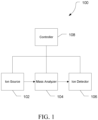
- mass spectrometry platform 100 can include components as displayed in the block diagram of Figure 1 . In various embodiments, elements of Figure 1 can be incorporated into mass spectrometry platform 100. According to various embodiments, mass spectrometer 100 can include an ion source 102, a mass analyzer 104, an ion detector 106, and a controller 108.
- the ion source 102 generates a plurality of ions from a sample.
- the ion source can include, but is not limited to, a matrix assisted laser desorption/ionization (MALDI) source, electrospray ionization (ESI) source, atmospheric pressure chemical ionization (APCI) source, atmospheric pressure photoionization source (APPI), inductively coupled plasma (ICP) source, electron ionization source, chemical ionization source, photoionization source, glow discharge ionization source, thermospray ionization source, and the like.
- MALDI matrix assisted laser desorption/ionization
- ESI electrospray ionization
- APCI atmospheric pressure chemical ionization
- APPI atmospheric pressure photoionization source
- ICP inductively coupled plasma
- the mass analyzer 104 can separate ions based on a mass to charge ratio of the ions.
- the mass analyzer 104 can include a quadrupole mass filter analyzer, a quadrupole ion trap analyzer, a time-of-flight (TOF) analyzer, an electrostatic trap (e.g., ORBITRAP) mass analyzer, Fourier transform ion cyclotron resonance (FT-ICR) mass analyzer, and the like.
- the mass analyzer 104 can also be configured to fragment the ions using collision induced dissociation (CID) electron transfer dissociation (ETD), electron capture dissociation (ECD), photo induced dissociation (PID), surface induced dissociation (SID), and the like, and further separate the fragmented ions based on the mass-to-charge ratio.
- CID collision induced dissociation
- ETD electron transfer dissociation
- ECD electron capture dissociation
- PID photo induced dissociation
- SID surface induced dissociation
- the ion detector 106 can detect ions.
- the ion detector 106 can include an electron multiplier, a Faraday cup, and the like. Ions leaving the mass analyzer can be detected by the ion detector.
- the ion detector can be quantitative, such that an accurate count of the ions can be determined.
- the controller 108 can communicate with the ion source 102, the mass analyzer 104, and the ion detector 106.
- the controller 108 can configure the ion source or enable/disable the ion source.
- the controller 108 can configure the mass analyzer 104 to select a particular mass range to detect.
- the controller 108 can adjust the sensitivity of the ion detector 106, such as by adjusting the gain.
- the controller 108 can adjust the polarity of the ion detector 106 based on the polarity of the ions being detected.
- the ion detector 106 can be configured to detect positive ions or be configured to detected negative ions.
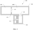
- FIG. 2 is cross section view illustrating an exemplary vacuum system 200 for a mass spectrometer.
- Vacuum system 200 can include mass spectrometer vacuum manifold 202 and high vacuum pump housing 204.
- the mass spectrometer vacuum manifold 202 can define ion source chamber 206 and high vacuum chamber 208.
- the ion source chamber 206 can house an ion source, such as ion source 102 of Figure 1
- the high vacuum chamber 208 can house a mass analyzer, such as mass analyzer 104 of Figure 1
- ion detector such as ion detector 108 of Figure 1
- the mass spectrometer vacuum manifold 202 can define one chamber and house the ion source, mass analyzer, and ion detector in the one chamber or have additional chambers such that the ion source, mass analyzer, and ion detector can be housed in separate chambers.
- the mass spectrometer vacuum manifold 202 can be a monolithic manifold, such as a manifold machined from a single block of material, or a multicomponent manifold, such as a manifold assembled from multiple pieces of material.
- Ion source chamber 206 and high vacuum chamber 208 can be separated by a baffle 210 having an aperture 212 therein to connect ion source chamber 206 and high vacuum chamber 208.
- High vacuum pump housing 204 can contain high vacuum pump 214.
- High vacuum chamber 208 can be coupled to high vacuum pump housing 204 via outlet 216.
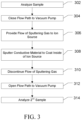
- Figure 3 is flow diagram illustrating a method 300 of applying a conductive layer to the interior of the ion source to improve robustness.
- a sample can be ionized in an ion source of a mass spectrometer, such as mass spectrometer 100, and the sample can be analyzed.
- the flow path to a high vacuum pump can be partially or fully closed to increase pressure in the ion source to a pressure suitable for sputtering, such as at least about 1 ⁇ 10 -3 Torr, preferably at least about 0.1 Torr.
- closing the flow path can include at least partially closing the entrance to the high vacuum pump, such as by closing a valve or moving a plate to block at least a portion of the entrance, such as outlet 216 of Figure 2 .
- the flow path can be closed at any point along the flow path between the ion source and the high vacuum pump.
- it can include isolating the ion source from other parts of the mass spectrometer to maintain vacuum in the rest of the mass spectrometer, such as by closing aperture 212 of Figure 2 .
- a flow of sputtering gas can be provided to the ion source.
- the sputtering gas can include argon, helium, neon, hydrogen, nitrogen, krypton, xenon, or any combination thereof.
- a coating of conductive material can be sputtered onto the interior surface of the ion source to form a conductive layer overtop any buildup of nonconductive material.
- the conductive material can be a metal such as gold, silver, rhenium, platinum, iridium, chromium, tungsten, molybdenum, copper, nickel chromium alloys, aluminum, titanium, or any combination thereof.
- the conductive material can be a conductive ceramic such as titanium nitride.
- the flow of sputter gas can be discontinued, and at 312, the flow path between the ion source and the high vacuum pump can be opened to restore the high vacuum needed for operation of the mass spectrometer.
- a second sample can be analyzed once the pressure has returned to an appropriate operating pressure for the mass spectrometer, such as less than about 1 ⁇ 10 -3 Torr, preferably less than about 5 ⁇ 10 -5 Torr.
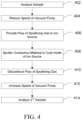
- Figure 4 is flow diagram illustrating a method 400 of applying a conductive layer to the interior of the ion source to improve robustness.
- a sample can be ionized in an ion source of a mass spectrometer, such as mass spectrometer 100, and the sample can be analyzed.
- the speed of a high vacuum pump can be reduced to increase pressure in the ion source to a pressure suitable for sputtering, such as at least about 1 ⁇ 10 -3 Torr, preferably at least about 0.1 Torr.
- a flow of sputtering gas can be provided to the ion source.
- the sputtering gas can include argon, helium, neon, hydrogen, nitrogen, krypton, xenon, or any combination thereof.
- a coating of conductive material can be sputtered onto the interior surface of the ion source to form a conductive layer overtop any buildup of nonconductive material.
- the conductive material can be a metal such as gold, silver, rhenium, platinum, iridium, chromium, tungsten, molybdenum, copper, nickel chromium alloys, aluminum, titanium, or any combination thereof.
- the conductive material can be a conductive ceramic such as titanium nitride.
- the flow of sputter gas can be discontinued, and at 412, the speed of the vacuum pump can be increased to restore the high vacuum needed for operation of the mass spectrometer, such as less than about 1 ⁇ 10 -3 Torr, preferably less than about 5 ⁇ 10 -5 Torr.
- a second sample can be analyzed once the pressure has returned to an appropriate operating pressure for the mass spectrometer.
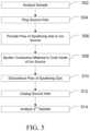
- Figure 5 is flow diagram illustrating a method 500 of applying a conductive layer to the interior of the ion source to improve robustness.
- a sample can be ionized in an ion source of a mass spectrometer, such as mass spectrometer 100, and the sample can be analyzed.
- the ion source can be isolated from the high vacuum pump.
- a probe can be inserted into the ion source to block at least a portion of the opening, such as through a vacuum interlock.
- the probe can be housed within the vacuum chamber and repositioned to block the opening.
- the probe can have an insulative cone shaped distal end for blocking the opening and a conductive shaft material as a source for the sputtered conducting coating.
- a flow of sputtering gas can be provided to the ion source.
- the sputtering gas can include argon, helium, neon, hydrogen, nitrogen, krypton, xenon, or any combination thereof. Blocking the opening and flowing the sputtering gas can increase the pressure within the ion source to a pressure suitable for sputtering, such as at least about 1 ⁇ 10 -3 Torr, preferably at least about 0.1 Torr.
- a coating of conductive material can be sputtered onto the interior surface of the ion source for form a conductive layer overtop any buildup of nonconductive material.
- the conductive material can be a metal such as gold, silver, rhenium, platinum, iridium, chromium, tungsten, molybdenum, copper, nickel chromium alloys, aluminum, titanium, or any combination thereof.
- the conductive material can be a conductive ceramic such as titanium nitride.
- the flow of sputter gas can be discontinued, and at 512, the opening of the ion source can be opened to reestablish the low pressure needed in the ion source, such as less than 1 ⁇ 10 -3 Torr, preferably less than about 5 ⁇ 10 -5 Torr.
- a second sample can be analyzed once the pressure has returned to an appropriate operating pressure for the mass spectrometer.
- the ion source can be coated following a sequence of many samples. However, it may be preferable to sputter the source components quasi-continuously by taking advantage of the time interval between analytical runs. Since the degradation is marginal for any given analytical run, a partial re-coat lasting only several seconds to a minute or two can be executed without interruption of the analytical sequence.
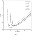
- Figure 7 illustrates the well known Pachen curves for various gasses. These curves indicate the breakdown potentials for a given pressure times electrode spacing which results in gas phase currents in the milliampere regime suitable for deposition of conducting films in a reasonable timeframe such as one or two minutes.
- the actual pressure may vary depending on the electrode spacing employed, but generally is in the range of 0.1 Torr and higher.
- a suitable method is to apply a high negative potential such as -2.5 kilovolts to a conventional ion source repeller made of or comprising a surface coated with gold.
- a counter electrode, such as the ion volume or extractor lens is maintained at lower potential such as earth ground in order to establish the necessary electric field.
- the power supply is preferably operated in current limiting mode with an adjustable current limit of 1 to 10 milliamperes.
- the pressure can be increased following the termination of potentials on other mass spectrometer components such as conversion dynodes, electron multipliers, ion guides, mass resolving multipoles and the like, in order to prevent unwanted gas discharge resulting in component damage.
- the pressure is increased until the onset of glow discharge and establishment of the target sputtering current.
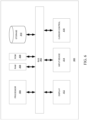
- FIG. 6 is a block diagram that illustrates a computer system 600, upon which embodiments of the present teachings may be implemented as which may incorporate or communicate with a system controller, for example controller 68 shown in Figure. 1 , such that the operation of components of the associated mass spectrometer may be adjusted in accordance with calculations or determinations made by computer system 600.
- computer system 600 can include a bus 602 or other communication mechanism for communicating information, and a processor 604 coupled with bus 602 for processing information.
- computer system 600 can also include a memory 606, which can be a random access memory (RAM) or other dynamic storage device, coupled to bus 602, and instructions to be executed by processor 604.
- RAM random access memory
- Memory 606 also can be used for storing temporary variables or other intermediate information during execution of instructions to be executed by processor 604.
- computer system 600 can further include a read only memory (ROM) 608 or other static storage device coupled to bus 602 for storing static information and instructions for processor 604.
- ROM read only memory
- a storage device 610 such as a magnetic disk or optical disk, can be provided and coupled to bus 602 for storing information and instructions.
- computer system 600 can be coupled via bus 602 to a display 612, such as a cathode ray tube (CRT) or liquid crystal display (LCD), for displaying information to a computer user.
- a display 612 such as a cathode ray tube (CRT) or liquid crystal display (LCD)
- An input device 614 can be coupled to bus 602 for communicating information and command selections to processor 604.
- a cursor control 616 such as a mouse, a trackball or cursor direction keys for communicating direction information and command selections to processor 604 and for controlling cursor movement on display 612.
- This input device typically has two degrees of freedom in two axes, a first axis (i.e., x) and a second axis (i.e., y), that allows the device to specify positions in a plane.
- a computer system 600 can perform the present teachings. Consistent with certain implementations of the present teachings, results can be provided by computer system 600 in response to processor 604 executing one or more sequences of one or more instructions contained in memory 606. Such instructions can be read into memory 606 from another computer-readable medium, such as storage device 610. Execution of the sequences of instructions contained in memory 606 can cause processor 604 to perform the processes described herein. In various embodiments, instructions in the memory can sequence the use of various combinations of logic gates available within the processor to perform the processes describe herein. Alternatively hard-wired circuitry can be used in place of or in combination with software instructions to implement the present teachings. In various embodiments, the hard-wired circuitry can include the necessary logic gates, operated in the necessary sequence to perform the processes described herein. Thus implementations of the present teachings are not limited to any specific combination of hardware circuitry and software.
- non-volatile media can include, but are not limited to, optical or magnetic disks, such as storage device 610.
- volatile media can include, but are not limited to, dynamic memory, such as memory 606.
- transmission media can include, but are not limited to, coaxial cables, copper wire, and fiber optics, including the wires that comprise bus 602.
- non-transitory computer-readable media include, for example, a floppy disk, a flexible disk, hard disk, magnetic tape, or any other magnetic medium, a CD-ROM, any other optical medium, punch cards, paper tape, any other physical medium with patterns of holes, a RAM, PROM, and EPROM, a FLASH-EPROM, any other memory chip or cartridge, or any other tangible medium from which a computer can read.
- instructions configured to be executed by a processor to perform a method are stored on a computer-readable medium.
- the computer-readable medium can be a device that stores digital information.
- a computer-readable medium includes a compact disc read-only memory (CD-ROM) as is known in the art for storing software.
- CD-ROM compact disc read-only memory
- the computer-readable medium is accessed by a processor suitable for executing instructions configured to be executed.
- the methods of the present teachings may be implemented in a software program and applications written in conventional programming languages such as C, C++, etc.
- the specification may have presented a method and/or process as a particular sequence of steps.
- the method or process should not be limited to the particular sequence of steps described.
- other sequences of steps may be possible. Therefore, the particular order of the steps set forth in the specification should not be construed as limitations on the claims.
- the claims directed to the method and/or process should not be limited to the performance of their steps in the order written, and one skilled in the art can readily appreciate that the sequences may be varied and still remain within the spirit and scope of the various embodiments.
- the embodiments described herein can be practiced with other computer system configurations including hand-held devices, microprocessor systems, microprocessor-based or programmable consumer electronics, minicomputers, mainframe computers and the like.
- the embodiments can also be practiced in distributing computing environments where tasks are performed by remote processing devices that are linked through a network.
- any of the operations that form part of the embodiments described herein are useful machine operations.
- the embodiments, described herein also relate to a device or an apparatus for performing these operations.
- the systems and methods described herein can be specially constructed for the required purposes or it may be a general purpose computer selectively activated or configured by a computer program stored in the computer.
- various general purpose machines may be used with computer programs written in accordance with the teachings herein, or it may be more convenient to construct a more specialized apparatus to perform the required operations.
- Certain embodiments can also be embodied as computer readable code on a computer readable medium.
- the computer readable medium is any data storage device that can store data, which can thereafter be read by a computer system. Examples of the computer readable medium include hard drives, network attached storage (NAS), read-only memory, random-access memory, CD-ROMs, CD-Rs, CD-RWs, magnetic tapes, and other optical and non-optical data storage devices.
- the computer readable medium can also be distributed over a network coupled computer systems so that the computer readable code is stored and executed in a distributed fashion.
Landscapes
- Chemical & Material Sciences (AREA)
- Analytical Chemistry (AREA)
- Chemical Kinetics & Catalysis (AREA)
- Physics & Mathematics (AREA)
- Health & Medical Sciences (AREA)
- Engineering & Computer Science (AREA)
- Life Sciences & Earth Sciences (AREA)
- Pathology (AREA)
- Immunology (AREA)
- General Physics & Mathematics (AREA)
- General Health & Medical Sciences (AREA)
- Biochemistry (AREA)
- Electrochemistry (AREA)
- Metallurgy (AREA)
- Organic Chemistry (AREA)
- Mechanical Engineering (AREA)
- Materials Engineering (AREA)
- Plasma & Fusion (AREA)
- Toxicology (AREA)
- Other Investigation Or Analysis Of Materials By Electrical Means (AREA)
Abstract
Description
- The present disclosure generally relates to the field of mass spectrometry including ion sources for improved robustness.
- Mass spectrometry can be used to perform detailed analyses on samples. Furthermore, mass spectrometry can provide both qualitative (is compound X present in the sample) and quantitative (how much of compound X is present in the sample) data for a large number of compounds in a sample. These capabilities have been used for a wide variety of analyses, such as to test for drug use, determine pesticide residues in food, monitor water quality, and the like.
- During use, the sensitivity of a mass spectrometer can degrade over time due to the build-up of dielectric deposits within the ion source. These deposits act as electrical insulators which alter the electric field experienced by ions, and thus the forces acting on them. Susceptible surfaces can include the cavity wherein ions are initially formed, along with various ion-optical components used to extract, guide, and focus ions into an ion guide or mass resolving multipole. In addition to sensitivity loss, mass resolution, mass accuracy and ion abundance ratios may suffer. As such, there is a need for improved ion sources.
Further aspects of the present disclosure as set forth in the following numbered clauses:- - Clause 1. A mass spectrometer system comprising:
- a vacuum manifold;
- an ion source positioned within the vacuum manifold for ionizing a sample;
- a mass analyzer positioned withing the vacuum manifold for analyzing sample ions;
- a high vacuum pump connected to the vacuum manifold operable to maintain the pressure within the vacuum manifold at an operating pressure; and
- a controller configured to:
- raise the pressure in the ion source to a sputtering pressure by supplying a flow of a sputtering gas and either reducing a speed of a high vacuum pump or isolating the ion source from the high vacuum pump;
- cause a conducting material to be sputtered on a surface of the ion source;
- reduce the pressure in the ion source to an operating pressure by reducing the flow of the sputtering gas and either increasing the speed of the high vacuum pump or restoring connectivity between the ion source and the high vacuum pump.
- Clause 2. The mass spectrometer system of clause 1 wherein the high vacuum pump is a turbo molecular pump.
- Clause 3. The mass spectrometer system of clause 1 wherein the sputtering gas includes argon, hydrogen, nitrogen, neon, helium, krypton, xenon, or any combination thereof.
- Clause 4. The mass spectrometer system of clause 1 wherein the conductive material includes a metal.
- Clause 5. The mass spectrometer system of clause 4 wherein the metal includes gold, silver, rhenium, platinum, iridium, chromium, tungsten, molybdenum, copper, nickel chromium alloys, aluminum, titanium, or any combination thereof.
- Clause 6. The mass spectrometer system of clause 1 wherein the conductive material includes titanium nitride.
- Clause 7. The mass spectrometer system of clause 1 wherein the controller is configured to isolate the ion source from the high vacuum pump by at least partially closing an entrance to the high vacuum pump from a vacuum manifold.
- Clause 8. The mass spectrometer system of clause 7 wherein at least partially closing the entrance to the high vacuum pump includes closing a valve.
- Clause 9. The mass spectrometer system of clause 7 wherein at least partially closing the entrance to the high vacuum pump includes moving a plate to block at least a portion of the entrance.
- Clause 10. The mass spectrometer system of clause 1 wherein the controller is configured to isolate the ion source from the high vacuum pump by at least partially closing an opening from the ion source to a vacuum manifold.
- Clause 11. The mass spectrometer system of clause 10 wherein at least partially closing the opening to the high vacuum pump includes moving a plate to block at least a portion of the opening.
- Clause 12. The mass spectrometer system of clause 11 wherein the plate is comprising the conductive material or is coated in the conductive material.
- Clause 13. The mass spectrometer system of clause 1 wherein the controller is configured to isolate the ion source by inserting a probe through a vacuum interlock into the ion source having an insulative cone shaped distal end for at least partially blocking the opening, and a conductive shaft material for sputtering.
- For a more complete understanding of the principles disclosed herein, and the advantages thereof, reference is now made to the following descriptions taken in conjunction with the accompanying drawings and exhibits, in which:
-
Figure 1 is a block diagram of an exemplary mass spectrometry system, in accordance with various embodiments. -
Figure 2 is a diagram illustrating an exemplary vacuum arrangement in a mass spectrometer, in accordance with various embodiments. -
Figures 3 ,4 , and5 are flow diagrams illustrating exemplary methods of coating the ion source with conductive material, in accordance with various embodiments. -
Figure 6 is a block diagram illustrating an exemplary computer system. -
Figure 7 are Paschen curves for various gasses illustrating Townsend avalanche voltages as a function of electrode spacing multiplied by pressure. - It is to be understood that the figures are not necessarily drawn to scale, nor are the objects in the figures necessarily drawn to scale in relationship to one another. The figures are depictions that are intended to bring clarity and understanding to various embodiments of apparatuses, systems, and methods disclosed herein. Wherever possible, the same reference numbers will be used throughout the drawings to refer to the same or like parts. Moreover, it should be appreciated that the drawings are not intended to limit the scope of the present teachings in any way.
- Embodiments of systems and methods for ion isolation are described herein and in the accompanying exhibits.
- The section headings used herein are for organizational purposes only and are not to be construed as limiting the described subject matter in any way.
- In this detailed description of the various embodiments, for purposes of explanation, numerous specific details are set forth to provide a thorough understanding of the embodiments disclosed. One skilled in the art will appreciate, however, that these various embodiments may be practiced with or without these specific details. In other instances, structures and devices are shown in block diagram form. Furthermore, one skilled in the art can readily appreciate that the specific sequences in which methods are presented and performed are illustrative and it is contemplated that the sequences can be varied and still remain within the spirit and scope of the various embodiments disclosed herein.
- All literature and similar materials cited in this application, including but not limited to, patents, patent applications, articles, books, treatises, and internet web pages are expressly incorporated by reference in their entirety for any purpose. Unless described otherwise, all technical and scientific terms used herein have a meaning as is commonly understood by one of ordinary skill in the art to which the various embodiments described herein belongs.
- It will be appreciated that there is an implied "about" prior to the temperatures, concentrations, times, pressures, flow rates, cross-sectional areas, etc. discussed in the present teachings, such that slight and insubstantial deviations are within the scope of the present teachings. In this application, the use of the singular includes the plural unless specifically stated otherwise. Also, the use of "comprise", "comprises", "comprising", "contain", "contains", "containing", "include", "includes", and "including" are not intended to be limiting. It is to be understood that both the foregoing general description and the following detailed description are exemplary and explanatory only and are not restrictive of the present teachings.
- As used herein, "a" or "an" also may refer to "at least one" or "one or more." Also, the use of "or" is inclusive, such that the phrase "A or B" is true when "A" is true, "B" is true, or both "A" and "B" are true. Further, unless otherwise required by context, singular terms shall include pluralities and plural terms shall include the singular.
- A "system" sets forth a set of components, real or abstract, comprising a whole where each component interacts with or is related to at least one other component within the whole.
- Various embodiments of
mass spectrometry platform 100 can include components as displayed in the block diagram ofFigure 1 . In various embodiments, elements ofFigure 1 can be incorporated intomass spectrometry platform 100. According to various embodiments,mass spectrometer 100 can include anion source 102, amass analyzer 104, anion detector 106, and acontroller 108. - In various embodiments, the
ion source 102 generates a plurality of ions from a sample. The ion source can include, but is not limited to, a matrix assisted laser desorption/ionization (MALDI) source, electrospray ionization (ESI) source, atmospheric pressure chemical ionization (APCI) source, atmospheric pressure photoionization source (APPI), inductively coupled plasma (ICP) source, electron ionization source, chemical ionization source, photoionization source, glow discharge ionization source, thermospray ionization source, and the like. - In various embodiments, the
mass analyzer 104 can separate ions based on a mass to charge ratio of the ions. For example, themass analyzer 104 can include a quadrupole mass filter analyzer, a quadrupole ion trap analyzer, a time-of-flight (TOF) analyzer, an electrostatic trap (e.g., ORBITRAP) mass analyzer, Fourier transform ion cyclotron resonance (FT-ICR) mass analyzer, and the like. In various embodiments, themass analyzer 104 can also be configured to fragment the ions using collision induced dissociation (CID) electron transfer dissociation (ETD), electron capture dissociation (ECD), photo induced dissociation (PID), surface induced dissociation (SID), and the like, and further separate the fragmented ions based on the mass-to-charge ratio. - In various embodiments, the
ion detector 106 can detect ions. For example, theion detector 106 can include an electron multiplier, a Faraday cup, and the like. Ions leaving the mass analyzer can be detected by the ion detector. In various embodiments, the ion detector can be quantitative, such that an accurate count of the ions can be determined. - In various embodiments, the
controller 108 can communicate with theion source 102, themass analyzer 104, and theion detector 106. For example, thecontroller 108 can configure the ion source or enable/disable the ion source. Additionally, thecontroller 108 can configure themass analyzer 104 to select a particular mass range to detect. Further, thecontroller 108 can adjust the sensitivity of theion detector 106, such as by adjusting the gain. Additionally, thecontroller 108 can adjust the polarity of theion detector 106 based on the polarity of the ions being detected. For example, theion detector 106 can be configured to detect positive ions or be configured to detected negative ions. -
Figure 2 is cross section view illustrating anexemplary vacuum system 200 for a mass spectrometer.Vacuum system 200 can include massspectrometer vacuum manifold 202 and highvacuum pump housing 204. - In various embodiments, the mass
spectrometer vacuum manifold 202 can defineion source chamber 206 and high vacuum chamber 208. Theion source chamber 206 can house an ion source, such asion source 102 ofFigure 1 , and the high vacuum chamber 208 can house a mass analyzer, such asmass analyzer 104 ofFigure 1 , and ion detector, such asion detector 108 ofFigure 1 . In other embodiments, the massspectrometer vacuum manifold 202 can define one chamber and house the ion source, mass analyzer, and ion detector in the one chamber or have additional chambers such that the ion source, mass analyzer, and ion detector can be housed in separate chambers. In various embodiments, the massspectrometer vacuum manifold 202 can be a monolithic manifold, such as a manifold machined from a single block of material, or a multicomponent manifold, such as a manifold assembled from multiple pieces of material. -
Ion source chamber 206 and high vacuum chamber 208 can be separated by abaffle 210 having anaperture 212 therein to connection source chamber 206 and high vacuum chamber 208. - High
vacuum pump housing 204 can containhigh vacuum pump 214. High vacuum chamber 208 can be coupled to highvacuum pump housing 204 viaoutlet 216. -
Figure 3 is flow diagram illustrating a method 300 of applying a conductive layer to the interior of the ion source to improve robustness. At 302, a sample can be ionized in an ion source of a mass spectrometer, such asmass spectrometer 100, and the sample can be analyzed. - At 304, the flow path to a high vacuum pump, such as a turbo molecular pump, can be partially or fully closed to increase pressure in the ion source to a pressure suitable for sputtering, such as at least about 1×10⁻³ Torr, preferably at least about 0.1 Torr. In various embodiments, closing the flow path can include at least partially closing the entrance to the high vacuum pump, such as by closing a valve or moving a plate to block at least a portion of the entrance, such as
outlet 216 ofFigure 2 . In other embodiments, the flow path can be closed at any point along the flow path between the ion source and the high vacuum pump. In some embodiments, it can include isolating the ion source from other parts of the mass spectrometer to maintain vacuum in the rest of the mass spectrometer, such as by closingaperture 212 ofFigure 2 . At 306, a flow of sputtering gas can be provided to the ion source. The sputtering gas can include argon, helium, neon, hydrogen, nitrogen, krypton, xenon, or any combination thereof. - At 308, a coating of conductive material can be sputtered onto the interior surface of the ion source to form a conductive layer overtop any buildup of nonconductive material. The conductive material can be a metal such as gold, silver, rhenium, platinum, iridium, chromium, tungsten, molybdenum, copper, nickel chromium alloys, aluminum, titanium, or any combination thereof. The conductive material can be a conductive ceramic such as titanium nitride.
- At 310, after coating the inside of the ion source with the conductive layer, the flow of sputter gas can be discontinued, and at 312, the flow path between the ion source and the high vacuum pump can be opened to restore the high vacuum needed for operation of the mass spectrometer.
- At 314, a second sample can be analyzed once the pressure has returned to an appropriate operating pressure for the mass spectrometer, such as less than about 1×10⁻³ Torr, preferably less than about 5×10⁻⁵ Torr.
-
Figure 4 is flow diagram illustrating a method 400 of applying a conductive layer to the interior of the ion source to improve robustness. At 402, a sample can be ionized in an ion source of a mass spectrometer, such asmass spectrometer 100, and the sample can be analyzed. - At 404, the speed of a high vacuum pump, such as a turbo molecular pump, can be reduced to increase pressure in the ion source to a pressure suitable for sputtering, such as at least about 1×10⁻³ Torr, preferably at least about 0.1 Torr. At 406, a flow of sputtering gas can be provided to the ion source. The sputtering gas can include argon, helium, neon, hydrogen, nitrogen, krypton, xenon, or any combination thereof.
- At 408, a coating of conductive material can be sputtered onto the interior surface of the ion source to form a conductive layer overtop any buildup of nonconductive material. The conductive material can be a metal such as gold, silver, rhenium, platinum, iridium, chromium, tungsten, molybdenum, copper, nickel chromium alloys, aluminum, titanium, or any combination thereof. The conductive material can be a conductive ceramic such as titanium nitride.
- At 410, after coating the inside of the ion source with the conductive layer, the flow of sputter gas can be discontinued, and at 412, the speed of the vacuum pump can be increased to restore the high vacuum needed for operation of the mass spectrometer, such as less than about 1×10⁻³ Torr, preferably less than about 5×10⁻⁵ Torr.
- At 414, a second sample can be analyzed once the pressure has returned to an appropriate operating pressure for the mass spectrometer.
-
Figure 5 is flow diagram illustrating a method 500 of applying a conductive layer to the interior of the ion source to improve robustness. At 502, a sample can be ionized in an ion source of a mass spectrometer, such asmass spectrometer 100, and the sample can be analyzed. - At 504, the ion source can be isolated from the high vacuum pump. In various embodiments, a probe can be inserted into the ion source to block at least a portion of the opening, such as through a vacuum interlock. In other embodiments, the probe can be housed within the vacuum chamber and repositioned to block the opening. The probe can have an insulative cone shaped distal end for blocking the opening and a conductive shaft material as a source for the sputtered conducting coating. At 506, a flow of sputtering gas can be provided to the ion source. The sputtering gas can include argon, helium, neon, hydrogen, nitrogen, krypton, xenon, or any combination thereof. Blocking the opening and flowing the sputtering gas can increase the pressure within the ion source to a pressure suitable for sputtering, such as at least about 1×10⁻³ Torr, preferably at least about 0.1 Torr.
- At 508, a coating of conductive material can be sputtered onto the interior surface of the ion source for form a conductive layer overtop any buildup of nonconductive material. The conductive material can be a metal such as gold, silver, rhenium, platinum, iridium, chromium, tungsten, molybdenum, copper, nickel chromium alloys, aluminum, titanium, or any combination thereof. The conductive material can be a conductive ceramic such as titanium nitride.
- At 510, after coating the inside of the ion source with the conductive layer, the flow of sputter gas can be discontinued, and at 512, the opening of the ion source can be opened to reestablish the low pressure needed in the ion source, such as less than 1×10⁻³ Torr, preferably less than about 5×10⁻⁵ Torr.
- At 514, a second sample can be analyzed once the pressure has returned to an appropriate operating pressure for the mass spectrometer.
- In various embodiments, the ion source can be coated following a sequence of many samples. However, it may be preferable to sputter the source components quasi-continuously by taking advantage of the time interval between analytical runs. Since the degradation is marginal for any given analytical run, a partial re-coat lasting only several seconds to a minute or two can be executed without interruption of the analytical sequence.
-
Figure 7 illustrates the well known Pachen curves for various gasses. These curves indicate the breakdown potentials for a given pressure times electrode spacing which results in gas phase currents in the milliampere regime suitable for deposition of conducting films in a reasonable timeframe such as one or two minutes. The actual pressure may vary depending on the electrode spacing employed, but generally is in the range of 0.1 Torr and higher. A suitable method is to apply a high negative potential such as -2.5 kilovolts to a conventional ion source repeller made of or comprising a surface coated with gold. A counter electrode, such as the ion volume or extractor lens is maintained at lower potential such as earth ground in order to establish the necessary electric field. The power supply is preferably operated in current limiting mode with an adjustable current limit of 1 to 10 milliamperes. The pressure can be increased following the termination of potentials on other mass spectrometer components such as conversion dynodes, electron multipliers, ion guides, mass resolving multipoles and the like, in order to prevent unwanted gas discharge resulting in component damage. The pressure is increased until the onset of glow discharge and establishment of the target sputtering current. -
Figure 6 is a block diagram that illustrates acomputer system 600, upon which embodiments of the present teachings may be implemented as which may incorporate or communicate with a system controller, for example controller 68 shown inFigure. 1 , such that the operation of components of the associated mass spectrometer may be adjusted in accordance with calculations or determinations made bycomputer system 600. In various embodiments,computer system 600 can include a bus 602 or other communication mechanism for communicating information, and aprocessor 604 coupled with bus 602 for processing information. In various embodiments,computer system 600 can also include amemory 606, which can be a random access memory (RAM) or other dynamic storage device, coupled to bus 602, and instructions to be executed byprocessor 604.Memory 606 also can be used for storing temporary variables or other intermediate information during execution of instructions to be executed byprocessor 604. In various embodiments,computer system 600 can further include a read only memory (ROM) 608 or other static storage device coupled to bus 602 for storing static information and instructions forprocessor 604. Astorage device 610, such as a magnetic disk or optical disk, can be provided and coupled to bus 602 for storing information and instructions. - In various embodiments,
computer system 600 can be coupled via bus 602 to adisplay 612, such as a cathode ray tube (CRT) or liquid crystal display (LCD), for displaying information to a computer user. Aninput device 614, including alphanumeric and other keys, can be coupled to bus 602 for communicating information and command selections toprocessor 604. Another type of user input device is acursor control 616, such as a mouse, a trackball or cursor direction keys for communicating direction information and command selections toprocessor 604 and for controlling cursor movement ondisplay 612. This input device typically has two degrees of freedom in two axes, a first axis (i.e., x) and a second axis (i.e., y), that allows the device to specify positions in a plane. - A
computer system 600 can perform the present teachings. Consistent with certain implementations of the present teachings, results can be provided bycomputer system 600 in response toprocessor 604 executing one or more sequences of one or more instructions contained inmemory 606. Such instructions can be read intomemory 606 from another computer-readable medium, such asstorage device 610. Execution of the sequences of instructions contained inmemory 606 can causeprocessor 604 to perform the processes described herein. In various embodiments, instructions in the memory can sequence the use of various combinations of logic gates available within the processor to perform the processes describe herein. Alternatively hard-wired circuitry can be used in place of or in combination with software instructions to implement the present teachings. In various embodiments, the hard-wired circuitry can include the necessary logic gates, operated in the necessary sequence to perform the processes described herein. Thus implementations of the present teachings are not limited to any specific combination of hardware circuitry and software. - The term "computer-readable medium" as used herein refers to any media that participates in providing instructions to
processor 604 for execution. Such a medium can take many forms, including but not limited to, non-volatile media, volatile media, and transmission media. Examples of non-volatile media can include, but are not limited to, optical or magnetic disks, such asstorage device 610. Examples of volatile media can include, but are not limited to, dynamic memory, such asmemory 606. Examples of transmission media can include, but are not limited to, coaxial cables, copper wire, and fiber optics, including the wires that comprise bus 602. - Common forms of non-transitory computer-readable media include, for example, a floppy disk, a flexible disk, hard disk, magnetic tape, or any other magnetic medium, a CD-ROM, any other optical medium, punch cards, paper tape, any other physical medium with patterns of holes, a RAM, PROM, and EPROM, a FLASH-EPROM, any other memory chip or cartridge, or any other tangible medium from which a computer can read.
- In accordance with various embodiments, instructions configured to be executed by a processor to perform a method are stored on a computer-readable medium. The computer-readable medium can be a device that stores digital information. For example, a computer-readable medium includes a compact disc read-only memory (CD-ROM) as is known in the art for storing software. The computer-readable medium is accessed by a processor suitable for executing instructions configured to be executed.
- In various embodiments, the methods of the present teachings may be implemented in a software program and applications written in conventional programming languages such as C, C++, etc.
- While the present teachings are described in conjunction with various embodiments, it is not intended that the present teachings be limited to such embodiments. On the contrary, the present teachings encompass various alternatives, modifications, and equivalents, as will be appreciated by those of skill in the art.
- Further, in describing various embodiments, the specification may have presented a method and/or process as a particular sequence of steps. However, to the extent that the method or process does not rely on the particular order of steps set forth herein, the method or process should not be limited to the particular sequence of steps described. As one of ordinary skill in the art would appreciate, other sequences of steps may be possible. Therefore, the particular order of the steps set forth in the specification should not be construed as limitations on the claims. In addition, the claims directed to the method and/or process should not be limited to the performance of their steps in the order written, and one skilled in the art can readily appreciate that the sequences may be varied and still remain within the spirit and scope of the various embodiments.
- The embodiments described herein, can be practiced with other computer system configurations including hand-held devices, microprocessor systems, microprocessor-based or programmable consumer electronics, minicomputers, mainframe computers and the like. The embodiments can also be practiced in distributing computing environments where tasks are performed by remote processing devices that are linked through a network.
- It should also be understood that the embodiments described herein can employ various computer-implemented operations involving data stored in computer systems. These operations are those requiring physical manipulation of physical quantities. Usually, though not necessarily, these quantities take the form of electrical or magnetic signals capable of being stored, transferred, combined, compared, and otherwise manipulated. Further, the manipulations performed are often referred to in terms, such as producing, identifying, determining, or comparing.
- Any of the operations that form part of the embodiments described herein are useful machine operations. The embodiments, described herein, also relate to a device or an apparatus for performing these operations. The systems and methods described herein can be specially constructed for the required purposes or it may be a general purpose computer selectively activated or configured by a computer program stored in the computer. In particular, various general purpose machines may be used with computer programs written in accordance with the teachings herein, or it may be more convenient to construct a more specialized apparatus to perform the required operations.
- Certain embodiments can also be embodied as computer readable code on a computer readable medium. The computer readable medium is any data storage device that can store data, which can thereafter be read by a computer system. Examples of the computer readable medium include hard drives, network attached storage (NAS), read-only memory, random-access memory, CD-ROMs, CD-Rs, CD-RWs, magnetic tapes, and other optical and non-optical data storage devices. The computer readable medium can also be distributed over a network coupled computer systems so that the computer readable code is stored and executed in a distributed fashion.
Claims (13)
- A method comprising:ionizing a sample using an ion source and analyze the sample using a mass analyzer;raising the pressure in the ion source to a sputtering pressure by supplying a flow of a sputtering gas and either reducing a speed of a high vacuum pump or isolating the ion source from the high vacuum pump;sputtering a conductive material on a surface of the ion source;reducing the pressure in the ion source to an operating pressure by reducing the flow of the sputtering gas and either increasing the speed of the high vacuum pump or restoring connectivity between the ion source and the high vacuum pump; andionizing a second sample using the ion source and analyze the second sample using the mass analyzer.
- The method of claim 1 wherein the high vacuum pump is a turbo molecular pump.
- The method of claim 1 wherein the sputtering gas includes argon, helium, neon, hydrogen, nitrogen, krypton, xenon, or any combination thereof.
- The method of claim 1 wherein isolating the ion source from the high vacuum pump includes at least partially closing an entrance to the high vacuum pump from a vacuum manifold.
- The method of claim 4 wherein at least partially closing the entrance to the high vacuum pump includes closing a valve.
- The method of claim 4 wherein closing the entrance to the high vacuum pump includes moving a plate to block at least a portion of the entrance.
- The method of claim 1 wherein isolating the ion source from the high vacuum pump includes at least partially closing an opening from the ion source to a vacuum manifold.
- The method of claim 7 wherein isolating the ion source from the high vacuum pump includes inserting a probe through a vacuum interlock into the ion source having an insulative cone shaped distal end for at least partially blocking the opening, and a conductive shaft material for sputtering.
- The method of claim 7 wherein at least partially closing the opening from the ion source to the high vacuum pump includes moving a plate to block at least a portion of the opening.
- The method of claim 9 wherein the plate is comprising the conductive material or is coated in the conductive material.
- The method of claim 1 wherein the conductive material includes a metal.
- The method of claim 11 wherein the metal includes gold, silver, rhenium, platinum, iridium, chromium, tungsten, molybdenum, copper, nickel chromium alloys, aluminum, titanium, or any combination thereof.
- The method of claim 1 wherein the conductive material includes titanium nitride.
Applications Claiming Priority (1)
| Application Number | Priority Date | Filing Date | Title |
|---|---|---|---|
| US18/050,532 US12444595B2 (en) | 2022-10-28 | 2022-10-28 | Ion sources for improved robustness |
Publications (2)
| Publication Number | Publication Date |
|---|---|
| EP4362062A1 true EP4362062A1 (en) | 2024-05-01 |
| EP4362062B1 EP4362062B1 (en) | 2025-05-28 |
Family
ID=88093602
Family Applications (1)
| Application Number | Title | Priority Date | Filing Date |
|---|---|---|---|
| EP23197970.9A Active EP4362062B1 (en) | 2022-10-28 | 2023-09-18 | Ion sources for improved robustness |
Country Status (3)
| Country | Link |
|---|---|
| US (1) | US12444595B2 (en) |
| EP (1) | EP4362062B1 (en) |
| CN (1) | CN117954303A (en) |
Citations (2)
| Publication number | Priority date | Publication date | Assignee | Title |
|---|---|---|---|---|
| US4135094A (en) * | 1977-07-27 | 1979-01-16 | E. I. Du Pont De Nemours And Company | Method and apparatus for rejuvenating ion sources |
| US20080121811A1 (en) * | 2003-12-12 | 2008-05-29 | Horsky Thomas N | Method and apparatus for extending equipment uptime in ion implantation |
Family Cites Families (1)
| Publication number | Priority date | Publication date | Assignee | Title |
|---|---|---|---|---|
| GB9820210D0 (en) | 1998-09-16 | 1998-11-11 | Vg Elemental Limited | Means for removing unwanted ions from an ion transport system and mass spectrometer |
-
2022
- 2022-10-28 US US18/050,532 patent/US12444595B2/en active Active
-
2023
- 2023-08-22 CN CN202311057770.5A patent/CN117954303A/en active Pending
- 2023-09-18 EP EP23197970.9A patent/EP4362062B1/en active Active
Patent Citations (2)
| Publication number | Priority date | Publication date | Assignee | Title |
|---|---|---|---|---|
| US4135094A (en) * | 1977-07-27 | 1979-01-16 | E. I. Du Pont De Nemours And Company | Method and apparatus for rejuvenating ion sources |
| US20080121811A1 (en) * | 2003-12-12 | 2008-05-29 | Horsky Thomas N | Method and apparatus for extending equipment uptime in ion implantation |
Also Published As
| Publication number | Publication date |
|---|---|
| EP4362062B1 (en) | 2025-05-28 |
| US20240145228A1 (en) | 2024-05-02 |
| US12444595B2 (en) | 2025-10-14 |
| CN117954303A (en) | 2024-04-30 |
Similar Documents
| Publication | Publication Date | Title |
|---|---|---|
| US10515789B2 (en) | Reducing detector wear during calibration and tuning | |
| US11908672B2 (en) | Precursor accumulation in a single charge state in mass spectrometry | |
| US20240234123A1 (en) | Method of Performing MS/MS of High Intensity Ion Beams Using a Bandpass Filtering Collision Cell to Enhance Mass Spectrometry Robustness | |
| US11875982B2 (en) | Multi-modal ionization for mass spectrometry | |
| US10950422B2 (en) | Optimizing quadrupole collision cell RF amplitude for tandem mass spectrometry | |
| US11728148B2 (en) | Method for top down proteomics using ExD and PTR | |
| US10886118B1 (en) | Ion source with mixed magnets | |
| US20240404646A1 (en) | Ms/Ms-Based Identification of Trisulfide Bonds | |
| US20180286656A1 (en) | Systems and methods for electron ionization ion sources | |
| US12444595B2 (en) | Ion sources for improved robustness | |
| CN111971778B (en) | Off-axis ionization device and system | |
| EP4453554B1 (en) | Method and systems for analyzing ions using differential mobility spectrometry and an ion guide comprising additional auxiliary electrodes | |
| US12531223B2 (en) | Mass spectrometry methods and systems for high pressure charge state control and/or fragmentation | |
| EP3147934B1 (en) | Systems and methods for multipole operation | |
| CN117153662A (en) | Time-of-flight mass spectrometry device and adjustment method therefor | |
| US20250069877A1 (en) | Method to Operate a Mass Spectrometer to Counteract Space Charge Effects | |
| CN116686065A (en) | A Method for Enhancing Mass Spectrometry Robustness by Performing MS/MS with a High Intensity Ion Beam Using a Bandpass Filtered Collision Cell | |
| Purves | The development and application of an electrospray ionisation ion trap/linear time-of-flight mass spectrometer |
Legal Events
| Date | Code | Title | Description |
|---|---|---|---|
| PUAI | Public reference made under article 153(3) epc to a published international application that has entered the european phase |
Free format text: ORIGINAL CODE: 0009012 |
|
| STAA | Information on the status of an ep patent application or granted ep patent |
Free format text: STATUS: THE APPLICATION HAS BEEN PUBLISHED |
|
| AK | Designated contracting states |
Kind code of ref document: A1 Designated state(s): AL AT BE BG CH CY CZ DE DK EE ES FI FR GB GR HR HU IE IS IT LI LT LU LV MC ME MK MT NL NO PL PT RO RS SE SI SK SM TR |
|
| STAA | Information on the status of an ep patent application or granted ep patent |
Free format text: STATUS: REQUEST FOR EXAMINATION WAS MADE |
|
| 17P | Request for examination filed |
Effective date: 20240809 |
|
| RBV | Designated contracting states (corrected) |
Designated state(s): AL AT BE BG CH CY CZ DE DK EE ES FI FR GB GR HR HU IE IS IT LI LT LU LV MC ME MK MT NL NO PL PT RO RS SE SI SK SM TR |
|
| GRAP | Despatch of communication of intention to grant a patent |
Free format text: ORIGINAL CODE: EPIDOSNIGR1 |
|
| STAA | Information on the status of an ep patent application or granted ep patent |
Free format text: STATUS: GRANT OF PATENT IS INTENDED |
|
| INTG | Intention to grant announced |
Effective date: 20241220 |
|
| GRAS | Grant fee paid |
Free format text: ORIGINAL CODE: EPIDOSNIGR3 |
|
| GRAA | (expected) grant |
Free format text: ORIGINAL CODE: 0009210 |
|
| STAA | Information on the status of an ep patent application or granted ep patent |
Free format text: STATUS: THE PATENT HAS BEEN GRANTED |
|
| AK | Designated contracting states |
Kind code of ref document: B1 Designated state(s): AL AT BE BG CH CY CZ DE DK EE ES FI FR GB GR HR HU IE IS IT LI LT LU LV MC ME MK MT NL NO PL PT RO RS SE SI SK SM TR |
|
| REG | Reference to a national code |
Ref country code: GB Ref legal event code: FG4D |
|
| REG | Reference to a national code |
Ref country code: CH Ref legal event code: EP |
|
| REG | Reference to a national code |
Ref country code: IE Ref legal event code: FG4D Ref country code: DE Ref legal event code: R096 Ref document number: 602023003683 Country of ref document: DE |
|
| REG | Reference to a national code |
Ref country code: NL Ref legal event code: MP Effective date: 20250528 |
|
| PG25 | Lapsed in a contracting state [announced via postgrant information from national office to epo] |
Ref country code: FI Free format text: LAPSE BECAUSE OF FAILURE TO SUBMIT A TRANSLATION OF THE DESCRIPTION OR TO PAY THE FEE WITHIN THE PRESCRIBED TIME-LIMIT Effective date: 20250528 Ref country code: ES Free format text: LAPSE BECAUSE OF FAILURE TO SUBMIT A TRANSLATION OF THE DESCRIPTION OR TO PAY THE FEE WITHIN THE PRESCRIBED TIME-LIMIT Effective date: 20250528 |
|
| PGFP | Annual fee paid to national office [announced via postgrant information from national office to epo] |
Ref country code: DE Payment date: 20250820 Year of fee payment: 3 |
|
| REG | Reference to a national code |
Ref country code: LT Ref legal event code: MG9D |
|
| PG25 | Lapsed in a contracting state [announced via postgrant information from national office to epo] |
Ref country code: NO Free format text: LAPSE BECAUSE OF FAILURE TO SUBMIT A TRANSLATION OF THE DESCRIPTION OR TO PAY THE FEE WITHIN THE PRESCRIBED TIME-LIMIT Effective date: 20250828 Ref country code: GR Free format text: LAPSE BECAUSE OF FAILURE TO SUBMIT A TRANSLATION OF THE DESCRIPTION OR TO PAY THE FEE WITHIN THE PRESCRIBED TIME-LIMIT Effective date: 20250829 |
|
| PG25 | Lapsed in a contracting state [announced via postgrant information from national office to epo] |
Ref country code: NL Free format text: LAPSE BECAUSE OF FAILURE TO SUBMIT A TRANSLATION OF THE DESCRIPTION OR TO PAY THE FEE WITHIN THE PRESCRIBED TIME-LIMIT Effective date: 20250528 Ref country code: PL Free format text: LAPSE BECAUSE OF FAILURE TO SUBMIT A TRANSLATION OF THE DESCRIPTION OR TO PAY THE FEE WITHIN THE PRESCRIBED TIME-LIMIT Effective date: 20250528 |
|
| PG25 | Lapsed in a contracting state [announced via postgrant information from national office to epo] |
Ref country code: BG Free format text: LAPSE BECAUSE OF FAILURE TO SUBMIT A TRANSLATION OF THE DESCRIPTION OR TO PAY THE FEE WITHIN THE PRESCRIBED TIME-LIMIT Effective date: 20250528 |
|
| PG25 | Lapsed in a contracting state [announced via postgrant information from national office to epo] |
Ref country code: HR Free format text: LAPSE BECAUSE OF FAILURE TO SUBMIT A TRANSLATION OF THE DESCRIPTION OR TO PAY THE FEE WITHIN THE PRESCRIBED TIME-LIMIT Effective date: 20250528 |
|
| PGFP | Annual fee paid to national office [announced via postgrant information from national office to epo] |
Ref country code: AT Payment date: 20251020 Year of fee payment: 3 |
|
| PG25 | Lapsed in a contracting state [announced via postgrant information from national office to epo] |
Ref country code: RS Free format text: LAPSE BECAUSE OF FAILURE TO SUBMIT A TRANSLATION OF THE DESCRIPTION OR TO PAY THE FEE WITHIN THE PRESCRIBED TIME-LIMIT Effective date: 20250828 |
|
| PG25 | Lapsed in a contracting state [announced via postgrant information from national office to epo] |
Ref country code: IS Free format text: LAPSE BECAUSE OF FAILURE TO SUBMIT A TRANSLATION OF THE DESCRIPTION OR TO PAY THE FEE WITHIN THE PRESCRIBED TIME-LIMIT Effective date: 20250928 |
|
| PG25 | Lapsed in a contracting state [announced via postgrant information from national office to epo] |
Ref country code: LV Free format text: LAPSE BECAUSE OF FAILURE TO SUBMIT A TRANSLATION OF THE DESCRIPTION OR TO PAY THE FEE WITHIN THE PRESCRIBED TIME-LIMIT Effective date: 20250528 |
|
| REG | Reference to a national code |
Ref country code: AT Ref legal event code: MK05 Ref document number: 1799137 Country of ref document: AT Kind code of ref document: T Effective date: 20250528 |
|
| PG25 | Lapsed in a contracting state [announced via postgrant information from national office to epo] |
Ref country code: DK Free format text: LAPSE BECAUSE OF FAILURE TO SUBMIT A TRANSLATION OF THE DESCRIPTION OR TO PAY THE FEE WITHIN THE PRESCRIBED TIME-LIMIT Effective date: 20250528 Ref country code: AT Free format text: LAPSE BECAUSE OF FAILURE TO SUBMIT A TRANSLATION OF THE DESCRIPTION OR TO PAY THE FEE WITHIN THE PRESCRIBED TIME-LIMIT Effective date: 20250528 Ref country code: SM Free format text: LAPSE BECAUSE OF FAILURE TO SUBMIT A TRANSLATION OF THE DESCRIPTION OR TO PAY THE FEE WITHIN THE PRESCRIBED TIME-LIMIT Effective date: 20250528 |
|
| PG25 | Lapsed in a contracting state [announced via postgrant information from national office to epo] |
Ref country code: CZ Free format text: LAPSE BECAUSE OF FAILURE TO SUBMIT A TRANSLATION OF THE DESCRIPTION OR TO PAY THE FEE WITHIN THE PRESCRIBED TIME-LIMIT Effective date: 20250528 |
|
| PG25 | Lapsed in a contracting state [announced via postgrant information from national office to epo] |
Ref country code: EE Free format text: LAPSE BECAUSE OF FAILURE TO SUBMIT A TRANSLATION OF THE DESCRIPTION OR TO PAY THE FEE WITHIN THE PRESCRIBED TIME-LIMIT Effective date: 20250528 |
|
| PG25 | Lapsed in a contracting state [announced via postgrant information from national office to epo] |
Ref country code: SK Free format text: LAPSE BECAUSE OF FAILURE TO SUBMIT A TRANSLATION OF THE DESCRIPTION OR TO PAY THE FEE WITHIN THE PRESCRIBED TIME-LIMIT Effective date: 20250528 |
|
| PG25 | Lapsed in a contracting state [announced via postgrant information from national office to epo] |
Ref country code: IT Free format text: LAPSE BECAUSE OF FAILURE TO SUBMIT A TRANSLATION OF THE DESCRIPTION OR TO PAY THE FEE WITHIN THE PRESCRIBED TIME-LIMIT Effective date: 20250528 |
|
| REG | Reference to a national code |
Ref country code: DE Ref legal event code: R097 Ref document number: 602023003683 Country of ref document: DE |
|
| PG25 | Lapsed in a contracting state [announced via postgrant information from national office to epo] |
Ref country code: RO Free format text: LAPSE BECAUSE OF FAILURE TO SUBMIT A TRANSLATION OF THE DESCRIPTION OR TO PAY THE FEE WITHIN THE PRESCRIBED TIME-LIMIT Effective date: 20250528 |
|
| PLBE | No opposition filed within time limit |
Free format text: ORIGINAL CODE: 0009261 |
|
| STAA | Information on the status of an ep patent application or granted ep patent |
Free format text: STATUS: NO OPPOSITION FILED WITHIN TIME LIMIT |
|
| REG | Reference to a national code |
Ref country code: CH Ref legal event code: L10 Free format text: ST27 STATUS EVENT CODE: U-0-0-L10-L00 (AS PROVIDED BY THE NATIONAL OFFICE) Effective date: 20260409 |
|
| 26N | No opposition filed |
Effective date: 20260303 |