EP4362053A1 - Direct current circuit breaker handcart and direct current switch apparatus - Google Patents
Direct current circuit breaker handcart and direct current switch apparatus Download PDFInfo
- Publication number
- EP4362053A1 EP4362053A1 EP23306565.5A EP23306565A EP4362053A1 EP 4362053 A1 EP4362053 A1 EP 4362053A1 EP 23306565 A EP23306565 A EP 23306565A EP 4362053 A1 EP4362053 A1 EP 4362053A1
- Authority
- EP
- European Patent Office
- Prior art keywords
- circuit breaker
- commutation
- direct current
- support surface
- main
- Prior art date
- Legal status (The legal status is an assumption and is not a legal conclusion. Google has not performed a legal analysis and makes no representation as to the accuracy of the status listed.)
- Granted
Links
Images


Classifications
-
- H—ELECTRICITY
- H01—ELECTRIC ELEMENTS
- H01H—ELECTRIC SWITCHES; RELAYS; SELECTORS; EMERGENCY PROTECTIVE DEVICES
- H01H3/00—Mechanisms for operating contacts
- H01H3/22—Power arrangements internal to the switch for operating the driving mechanism
-
- H—ELECTRICITY
- H01—ELECTRIC ELEMENTS
- H01H—ELECTRIC SWITCHES; RELAYS; SELECTORS; EMERGENCY PROTECTIVE DEVICES
- H01H33/00—High-tension or heavy-current switches with arc-extinguishing or arc-preventing means
- H01H33/02—Details
- H01H33/59—Circuit arrangements not adapted to a particular application of the switch and not otherwise provided for, e.g. for ensuring operation of the switch at a predetermined point in the AC cycle
- H01H33/596—Circuit arrangements not adapted to a particular application of the switch and not otherwise provided for, e.g. for ensuring operation of the switch at a predetermined point in the AC cycle for interrupting DC
-
- H—ELECTRICITY
- H02—GENERATION; CONVERSION OR DISTRIBUTION OF ELECTRIC POWER
- H02B—BOARDS, SUBSTATIONS OR SWITCHING ARRANGEMENTS FOR THE SUPPLY OR DISTRIBUTION OF ELECTRIC POWER
- H02B11/00—Switchgear having carriage withdrawable for isolation
- H02B11/12—Switchgear having carriage withdrawable for isolation with isolation by horizontal withdrawal
- H02B11/167—Switchgear having carriage withdrawable for isolation with isolation by horizontal withdrawal truck type
-
- H—ELECTRICITY
- H01—ELECTRIC ELEMENTS
- H01H—ELECTRIC SWITCHES; RELAYS; SELECTORS; EMERGENCY PROTECTIVE DEVICES
- H01H1/00—Contacts
- H01H1/50—Means for increasing contact pressure, preventing vibration of contacts, holding contacts together after engagement, or biasing contacts to the open position
-
- H—ELECTRICITY
- H01—ELECTRIC ELEMENTS
- H01H—ELECTRIC SWITCHES; RELAYS; SELECTORS; EMERGENCY PROTECTIVE DEVICES
- H01H9/00—Details of switching devices, not covered by groups H01H1/00 - H01H7/00
- H01H9/02—Bases, casings, or covers
-
- H—ELECTRICITY
- H02—GENERATION; CONVERSION OR DISTRIBUTION OF ELECTRIC POWER
- H02B—BOARDS, SUBSTATIONS OR SWITCHING ARRANGEMENTS FOR THE SUPPLY OR DISTRIBUTION OF ELECTRIC POWER
- H02B11/00—Switchgear having carriage withdrawable for isolation
- H02B11/02—Details
- H02B11/04—Isolating-contacts, e.g. mountings or shieldings
-
- H—ELECTRICITY
- H02—GENERATION; CONVERSION OR DISTRIBUTION OF ELECTRIC POWER
- H02H—EMERGENCY PROTECTIVE CIRCUIT ARRANGEMENTS
- H02H7/00—Emergency protective circuit arrangements specially adapted for specific types of electric machines or apparatus or for sectionalised protection of cable or line systems, and effecting automatic switching in the event of an undesired change from normal working conditions
- H02H7/22—Emergency protective circuit arrangements specially adapted for specific types of electric machines or apparatus or for sectionalised protection of cable or line systems, and effecting automatic switching in the event of an undesired change from normal working conditions for distribution gear, e.g. bus-bar systems; for switching devices
-
- H—ELECTRICITY
- H01—ELECTRIC ELEMENTS
- H01H—ELECTRIC SWITCHES; RELAYS; SELECTORS; EMERGENCY PROTECTIVE DEVICES
- H01H9/00—Details of switching devices, not covered by groups H01H1/00 - H01H7/00
- H01H9/54—Circuit arrangements not adapted to a particular application of the switching device and for which no provision exists elsewhere
- H01H9/541—Contacts shunted by semiconductor devices
- H01H9/542—Contacts shunted by static switch means
- H01H2009/543—Contacts shunted by static switch means third parallel branch comprising an energy absorber, e.g. MOV, PTC, Zener
Definitions
- At least one embodiment of the present disclosure relates to a direct current circuit breaker handcart and a direct current switch apparatus.
- a direct current switch cabinet is also called a direct current cabinet, is a kind of power distribution equipment that provides stable direct current power supply for electrical equipment, also serves as an operating power supply and a signal alarm equipment, and can provide stable power supply for a large and complex high and low voltage power distribution system.
- a traditional direct current switch cabinet is provided with a plurality of control elements that are separated from each other, and these control elements can monitor and deal with a power supply failure caused by breaking off of a power supply element, overcharging of a charging element, and the like. Designing a direct current switch apparatus with convenient operation and high reliability performance is the key to realize effective monitoring and maintenance for each power supply element.
- At least one embodiment of the present disclosure provides a direct current circuit breaker handcart and a direct current switch apparatus.
- At least one embodiment of the present disclosure provides a direct current circuit breaker handcart, including: a support frame, a current carrying element, a commutation element, a repulsive assembly, and an energy absorbing element.
- the support frame includes a support surface.
- the current carrying element is located on the support surface, and includes a main circuit breaker and an auxiliary circuit breaker that are electrically connected with each other.
- the commutation element is located on the support surface, is electrically connected with the current carrying element, and includes a commutation capacitor, a commutation inductor, a commutation switch assembly, and a commutation capacitor charger that are electrically connected with each other.
- the repulsive assembly is configured to control opening and breaking off of the main circuit breaker.
- the energy absorbing element is located on the support surface, and is electrically connected with the current carrying element and the commutation element, respectively.
- the support frame includes a first end and a second end that are opposite in a first direction
- the main circuit breaker and the auxiliary circuit breaker are located at the first end, and are spaced apart from each other in a second direction
- the first direction and the second direction are parallel to the support surface
- the first direction is perpendicular to the second direction
- the main circuit breaker includes a main switch and a first contact arm
- the auxiliary circuit breaker includes an auxiliary switch and a second contact arm
- the first contact arm and the second contact arm both extend in the first direction and in a direction pointing from the first end to the second end
- one end of the first contact arm close to the first end is connected with one end of the main switch
- one end of the second contact arm close to the first end is connected with one end of the auxiliary switch
- the other end of the main switch is electrically connected with the other end of the auxiliary switch through a conductive element, and both the first contact arm and the second contact arm are farther away from the support surface
- the commutation capacitor is electrically connected with the commutation capacitor charger, and is located on a side of the main circuit breaker close to the auxiliary circuit breaker in the second direction, the commutation capacitor charger is located at the first end, and is located on a side of the auxiliary circuit breaker close to the support surface; the commutation capacitor is located at the second end, and is located on a side of the auxiliary circuit breaker close to the support surface, and an orthographic projection of the commutation capacitor on the support surface at least partially overlaps with an orthographic projection of at least one of the main circuit breaker and the auxiliary circuit breaker on the support surface.
- the commutation switch assembly is electrically connected with the commutation inductor and the commutation capacitor, respectively, and the commutation switch assembly includes a first commutation switch assembly and a second commutation switch assembly, the first commutation switch assembly and the second commutation switch assembly are electrically connected with each other, and are both located on a side of the commutation capacitor away from the support surface, and the first commutation switch assembly and the second commutation switch assembly are each of an integrated structure, in the third direction, the first commutation switch assembly and the second commutation switch assembly are located between the support surface and the first contact arm, and are located between the support surface and the second contact arm.
- the repulsive assembly includes a repulsive capacitor and a repulsive capacitor charger, the repulsive capacitor charger is electrically connected with the repulsive capacitor, and the repulsive capacitor charger is configured to charge the repulsive capacitor, both the repulsive capacitor and the repulsive capacitor charger are located at the first end, and are located on a side of the main circuit breaker close to the auxiliary circuit breaker in the second direction, and the repulsive capacitor charger is located on a side of the auxiliary circuit breaker close to the support surface in the third direction, the repulsive capacitor is located on a side of the repulsive capacitor charger away from the support surface, and the repulsive capacitor and the auxiliary circuit breaker are spaced apart from each other in the first direction.
- the direct current circuit breaker handcart further includes a circuit breaker controller configured to transmit control signals to the main circuit breaker and the auxiliary circuit breaker, the circuit breaker controller is located at the first end, and is located on a side of the main circuit breaker close to the support surface in the third direction, and is adjacent to and spaced apart from the repulsive capacitor charger in the second direction.
- a circuit breaker controller configured to transmit control signals to the main circuit breaker and the auxiliary circuit breaker
- the circuit breaker controller is located at the first end, and is located on a side of the main circuit breaker close to the support surface in the third direction, and is adjacent to and spaced apart from the repulsive capacitor charger in the second direction.
- the energy absorbing element includes a main arrester and a commutation switch arrester
- the main arrester is configured to absorb system energy after opening of the main circuit breaker to reduce voltage impact on the main circuit breaker
- the commutation switch arrester is configured to reduce voltage impact on the commutation switch assembly
- the main arrester is connected with the commutation switch arrester to form an integrated structure, and is located at the second end and on a side of the commutation capacitor close to the main circuit breaker in the second direction
- the energy absorbing element is located between the support surface and the main circuit breaker in the third direction.
- the main arrester includes a plurality of main arrester units electrically connected with each other, the plurality of main arrester units are arranged in an array in the first direction and the third direction to form a plurality of main arrester unit rows and a plurality of main arrester unit columns;
- the commutation switch arrester includes a plurality of commutation switch arrester units electrically connected with each other, the plurality of commutation switch arrester units are located on a side of the plurality of main arrester units away from the main circuit breaker, and the plurality of commutation switch arrester units are arranged in the third direction to form a plurality of commutation switch arrester unit columns.
- an orthographic projection of the second commutation switch assembly on the support surface is in a shape of "I".
- the direct current circuit breaker handcart further includes: a moving part located on a side of the support surface away from the current carrying element, the commutation element, and the energy absorbing element, and the moving part is configured to drive the support frame to move.
- the direct current circuit breaker handcart further includes a moving control device, the moving control device is connected with the support frame and is configured to control the moving part so as to drive the support frame to move, the moving control device is located at the first end, and is located on a side of the main circuit breaker away from the second end in a first direction.
- the support frame further includes at least two support beams, the at least two support beams are connected with the support surface;
- the direct current circuit breaker handcart further includes a lifting frame, and the lifting frame is detachably connected with the at least two support beams.
- the commutation inductor is located on a side of the commutation capacitor charger away from the support surface in the third direction, and is located between the main circuit breaker and the auxiliary circuit breaker in the second direction;
- the direct current circuit breaker handcart further includes an isolation transformer, the isolation transformer is electrically connected with the commutation switch assembly, and is located on a side of the commutation capacitor away from the support surface, and is adjacent to and spaced apart from the commutation switch assembly.
- At least one embodiment of the present disclosure further provides a direct current switch apparatus, including any one of the direct current circuit breaker handcarts as described above, and a direct current switch cabinet; the direct current switch cabinet includes a first static contact and a second static contact, the first static contact is configured to be detachably connected with the main circuit breaker, and the second static contact is configured to be detachably connected with the auxiliary circuit breaker.
- the features such as “vertical”, “parallel” and “same” used in the embodiments of the present disclosure all include features such as “vertical”, “parallel” and “same” in a strict sense, as well as cases where “approximately vertical”, “approximately parallel” and “approximately same” contain certain errors, considering the measurement and the errors related to the measurement of a specific quantity (that is, limitations of measurement system), the wording of approximately is within the acceptable deviation range for a specific value determined by a person of ordinary skill in the art.
- the “center” in the embodiment of the present disclosure may include a strictly geometric center position and a roughly central position in a small area around the geometric center. For example, “approximately” may indicate within one or more standard deviations, or within 10% or 5% of the stated value.
- the direct current switch apparatus may include a direct current switch cabinet.
- the direct current switch cabinet usually includes a plurality of elements such as a breaker, a charger, a capacitor, an inductor, and a switch controller, and the like, the elements are integrated together according to a specific topology circuit to realize detection, control and maintenance for a direct current power supply system.
- the direct current switch cabinet in the market is a fixed-type cabinet, that is, respective elements are directly installed in the direct current switch cabinet, upon assembling, transporting, overhauling and maintaining the elements, an overhaul person need to enter into the direct current switch cabinet for operation, which makes the operation inconvenient and may bring lacking of reliability risks.
- At least one embodiment of the present disclosure provides a direct current circuit breaker handcart and a direct current switch apparatus.
- the direct current circuit breaker handcart includes a support frame, a current carrying element, a commutation element, and an energy absorbing element.
- the support frame includes a support surface.
- the current carrying element is located on the support surface and includes a main circuit breaker and an auxiliary circuit breaker that are electrically connected with each other.
- the commutation element is located on the support surface, is electrically connected with the current carrying element and the commutation element, and includes a commutation capacitor, a commutation inductor, a commutation switch assembly, and a commutation capacitor charger that are electrically connected with each other.
- a repulsive assembly is configured to control opening and breaking off of the main circuit breaker.
- the energy absorbing element is located on the support surface and is electrically connected with the current carrying element.
- the direct current circuit breaker handcart provided by at least one embodiment of the present disclosure can facilitate the assembly, transportation, inspection and maintenance of a plurality of elements in the direct current cabinet by integrating main elements in a direct current handcart, which effectively improves control convenience and reliability performance of the direct current cabinet.
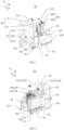
- FIG. 1 is a perspective view of a direct current circuit breaker handcart provided by at least one embodiment of the present disclosure.
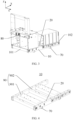
- FIG. 2 is another perspective view of the direct current circuit breaker handcart provided by at least one embodiment of the present disclosure.
- FIG. 3 is a perspective view of a direct current circuit breaker handcart without carrying elements provided by at least one embodiment of the present disclosure.
- FIG. 4 is a perspective view of a support frame provided by at least one embodiment of the present disclosure.
- the direct current circuit breaker handcart 01 includes a support frame 10, a current carrying element 30, a commutation element 40, a repulsive assembly 33 and an energy absorbing element 50.
- the support frame 10 can be used as a transport carrier for the direct current circuit breaker handcart 01.
- the support frame 10 can be designed to be movable, so as to facilitate moving each element to a position convenient for operation in a practical application.
- some fixed frames can further be arranged on the support frame 10 according to actual needs, so as to facilitate placement and fixing for the elements.
- some movable frames can further be designed on the support frame 10, so as to facilitate extraction and re retraction of the elements arranged thereon.
- the movable frame can be drawer-type, but it is not limited to this. Embodiments of the present disclosure do not limit a specific structure of the support frame 10.
- the support frame 10 may be a chassis structure, and the support surface 20 may be a surface of the chassis structure and may be at a side of the chassis structure close to the plurality of elements.
- the plurality of elements can be loaded on the support surface 20.
- the support surface 20 may not be a plane in the strict sense.
- the support surface 20 may have a certain degree of undulation, but it is not limited to this.
- the chassis structure may be plate-shaped or partially hollow frame, and the embodiments of the present disclosure does not limit a material and a specific shape of the support frame 10.
- the current carrying element 30 is located on the support surface 20 and includes a main circuit breaker 31 and an auxiliary circuit breaker 32 that are electrically connected with each other.
- the repulsive assembly 33 is configured to control opening and breaking off of the main circuit breaker 31.
- the main circuit breaker 31 is connected in series with the auxiliary circuit breaker 32.
- the main circuit breaker 31 is configured to quickly break a line fault and the auxiliary circuit breaker 32 is configured to cut off an entire line at last.
- the commutation element 40 is located on the support surface 20, is electrically connected with the current carrying element 30, and includes a commutation capacitor 41, a commutation inductor 43, a commutation switch assembly 44, and a commutation capacitor charger 42 that are electrically connected with each other.
- the commutation capacitor 41, the commutation switch assembly 44, and the commutation inductor 43 can be connected in series in sequence, and a branch formed is connected in parallel at two ends of the main circuit breaker 31.
- the commutation capacitor charger 42 is configured to charge the commutation capacitor 41, but it is not limited to this.
- the energy absorbing element 50 is located on the support surface 20 and is electrically connected with the current carrying element 30 and the commutation element 40, respectively.
- the energy absorbing element 50 may include elements such as an arrester and a varistor to absorb residual energy after breaking off a line fault, but it is not limited to this.
- the energy absorbing element 50 may include a main arrester 51 and a commutation switch arrester 52, the main arrester 51 is configured to absorb system energy after the opening of the main circuit breaker 31, and reduce voltage impact on the main circuit breaker 31, and the commutation switch arrester 52 is configured to reduce voltage impact on the commutation switch assembly 44.
- the embodiments of the present disclosure integrate the main elements of the direct current cabinet on the direct current circuit breaker handcart 01, which can facilitate the assembly, transportation, inspection, and maintenance of a plurality of elements in the direct current cabinet, and effectively improves control convenience and reliability performance of the direct current cabinet.
- the embodiments of the present disclosure rationalize spatial relative positions of the elements of the direct current circuit breaker handcart under a condition of satisfying electrical connection between the elements, and the shape and the structure of the element is optimized, so that the elements have a high integration degree after being installed on the direct current circuit breaker handcart.
- a weight of the direct current circuit breaker handcart is reduced and an occupied space is reduced to facilitate assembly, maintenance, and replacement of various elements.
- FIG. 5 is a perspective view of a main circuit breaker provided by at least one embodiment of the present disclosure.
- FIG. 6 is a perspective view of an auxiliary circuit breaker provided by at least one embodiment of the present disclosure.
- the support frame 10 includes a first end 101 and a second end 102 that are opposite to each other in a first direction X.
- Both the main circuit breaker 31 and the auxiliary circuit breaker 32 are located at the first end 101, and are spaced apart from each other in the second direction Y.
- An element located at the first end 101 here refers to that most of a structure of the element is located on the support frame 10 and is close to the first end 101
- an element located at the second end 102 refers to that most of a structure of the element is located on the support frame 10 and is close to the second end 102.
- the main circuit breaker 31 includes a main switch 311 and a first contact arm 312.
- the main circuit breaker 31 may include an upper chamber 313 and a lower chamber 314 that are communicated with each other in a third direction Z, the main switch 311 is located in the upper chamber 313, and the lower chamber 314 may further be provided with a main control mechanism for controlling opening and closing of the main switch 311.
- An end of the first contact arm 312 close to the first end 101 is connected with an end of the main switch 311.
- An end of the first contact arm 312 close to the second end 102 may include a first movable contact that is connected with the direct current cabinet.
- the auxiliary circuit breaker 32 includes an auxiliary switch 321 and a second contact arm 322.
- the auxiliary circuit breaker 32 may include an upper chamber 323 and a lower chamber 324 that are communicated with each other in the third direction Z, the auxiliary switch 321 is located in the upper chamber 323, and the lower chamber 324 may further be provided with an auxiliary control mechanism for controlling opening and closing of the auxiliary switch 321.
- An end of the second contact arm 322 close to the first end 101 is connected with an end of the auxiliary switch 321.
- An end of the second contact arm 322 close to the second end 102 may include a second movable contact that is connected with the direct current cabinet. Both the first contact arm 312 and the second contact arm 322 extend in the first direction X and in a direction pointing from the first end 101 to the second end 102.
- the other end of the main switch 311 is electrically connected with the other end of the auxiliary switch 321 through a conductive element 45, and the first contact arm 312 and the second contact arm 322 are both farther away from the support surface 20 in a third direction Z than the conductive element 45. Therefore, a space between the first contact arm 312 and the support surface 20 and a space between the second contact arm 322 and the support surface 20 can be reserved for placing other elements.
- the conductive element 45 can be a copper bar, but it is not limited to this.
- the first direction X and the second direction Y are both parallel to the support surface 20, and the first direction X is perpendicular to the second direction Y, the third direction Z is perpendicular to the first direction X, and the third direction Z is perpendicular to the second direction Y.
- FIG. 7A is a connection wiring diagram of a direct current circuit breaker handcart provided by at least one embodiment of the present disclosure.
- FIG. 7B is a connection wiring diagram of a direct current circuit breaker handcart.
- the direct current cabinet in a mode one, includes a first static contact and a second static contact, a connection end corresponding to the first static contact is B1, and a connection end corresponding to the second static contact is B2.
- a connection end corresponding to the first movable contact of the first contact arm 312 is Al, and a corresponding connection end in a case where the main circuit breaker 31 is connected with the conductive element 45 is A2.
- a corresponding connection end of the second movable contact of the second contact arm 322 is C1, and a corresponding connection end in a case where the auxiliary circuit breaker 32 is connected with the conductive element 45 is C2.
- the first movable contact and the second movable contact can be respectively connected with the corresponding first static contact and the second static contact in the direct current cabinet, so that the main switch 311 of the main circuit breaker 31 and the auxiliary switch 321 of the auxiliary circuit breaker 32 can be closed (with reference to FIG. 5 and FIG. 6 ).
- a path is formed by sequentially connecting the first static contact, the first movable contact, the main switch 311, the conductive element 45, the auxiliary switch 321, the second movable contact, and the second static contact (that is, a path formed by B1-A1-A2-C2-C1-B2 is connected), and the path is connected with a main loop of the direct current cabinet.
- the direct current cabinet in a mode two, includes a connection end H1 corresponding to a first static contact, a connection end H2 corresponding to a second static contact, a connection end K1 corresponding to a third static contact, and a connection end K2 corresponding to a fourth static contact.
- the main switch includes a connection end L1 corresponding to a first movable contact and a connection end L2 corresponding to a third movable contact
- the auxiliary switch includes a connection end M1 corresponding to a second movable contact and a connection end M4 corresponding to a fourth movable contact.
- the first movable contact and the second movable contact can be respectively connected with corresponding first static contact and the second static contact in the direct current cabinet
- the third movable contact and the fourth movable contact can be respectively connected with corresponding third static contact and fourth static contact in the direct current cabinet, so that the main switch and the auxiliary switch can be closed.
- a path is formed by sequentially connecting the first static contact, the first movable contact, the main switch, the third movable contact, the third static contact, the fourth static contact, the fourth movable contact, the auxiliary switch, the second movable contact, and the second static contact (that is, a path formed by H1-L1-L2-K1-K2-M2-M1-H2 is connected), and the path is connected with the main loop of the direct current cabinet.
- the embodiments of the present disclosure adopts a connection method in mode one. Compared with the mode two, this connection method realizes a circuit connection between an end of the main circuit breaker 31 away from the direct current cabinet and an end of the auxiliary circuit breaker 32 away from the direct current cabinet by the conductive element 45.
- the main circuit breaker 31 and the auxiliary circuit breaker 32 each can be connected with only one contact arm, so that a size of the direct current circuit breaker handcart 01 in the first direction X can be shortened, and a plurality of elements can be arranged between the first contact arm 312 and the support surface 20, or between the second contact arm 322 and the support surface 20, so as to improve a space utilization rate of the direct current circuit breaker handcart 01.
- the connection structure of the circuit in this connection method is simple and easy to implement.
- the commutation capacitor 41 is electrically connected with the commutation capacitor charger 42, and both of the commutation capacitor 41 and the commutation capacitor charger 42 are located on a side of the main circuit breaker 31 close to the auxiliary circuit breaker 32 in the second direction Y.
- the commutation capacitor charger 42 is located at the first end 101 and is on a side of the auxiliary circuit breaker 32 close to the support surface 20.
- the commutation capacitor 41 is located at the second end 102, and is located on a side of the auxiliary circuit breaker 32 close to the support surface 20, and an orthographic projection of the commutation capacitor 41 on the support surface 20 at least partially overlaps with an orthographic projection of the main circuit breaker 31 on the support surface 20.
- the orthographic projection of the commutation capacitor 41 on the support surface 20 at least partially overlaps with an orthographic projection of the auxiliary circuit breaker 32 on the support surface 20.
- the orthographic projection of the commutation capacitor 41 on the support surface 20 at least partially overlaps with both of the orthographic projection of the main circuit breaker 31 on the support surface 20 and the orthographic projection of the auxiliary circuit breaker 32 on the support surface 20.
- a size of the commutation capacitor 41 and a size of the commutation capacitor charger 42 in the second direction Y are both smaller than a size of the direct current circuit breaker handcart 01 in the second direction Y, and both of the commutation capacitor 41 and the commutation capacitor charger 42 are located on the same side of the direct current circuit breaker handcart 01 in the second direction Y, which is beneficial for the commutation capacitor charger 42 to charge the commutation capacitor 41.
- the control and the maintenance can be facilitated.
- the orthographic projection of the commutation capacitor 41 on the support surface 20 at least partially overlaps with the orthographic projection of the main circuit breaker 31 on the support surface 20.
- the orthographic projection of the commutation capacitor 41 on the support surface 20 at least partially overlaps with the orthographic projection of the auxiliary circuit breaker 32 on the support surface 20.
- the orthographic projection of the commutation capacitor 41 on the support surface 20 at least partially overlaps with the orthographic projection of the main circuit breaker 31 on the support surface 20 and the orthographic projection of the auxiliary circuit breaker 32 on the support surface 20. In this way, a space between the main circuit breaker 31 and the support surface 20 and a space between the auxiliary circuit breaker 32 and the support surface 20 can be effectively utilized, so that a space structure of the direct current circuit breaker handcart 01 is more compact.
- the commutation capacitor 41 is roughly in a shape of a cuboid and includes two parts arranged by stacking. One end of the commutation capacitor 41 can be connected with both of one end of the main circuit breaker 31 and one end of the main arrester 51, and the other end of the commutation capacitor 41 can be connected with the commutation switch assembly 44 and the commutation switch arrester 52 (with reference to FIG. 2 ).
- connection ends of the commutation capacitor 41 are only exemplary, and in different application scenarios, the number can be determined according to different needs, which is not limited in the embodiments of the present disclosure.
- the commutation capacitor 41 can further only be provided with several connection ends on one side, and on the other side, the commutation capacitor 41 can be electrically connected with other elements by directly leading out connection lines (for example, an electric line), and therefore the space can be further saved, and the convenience of electrical connection can be satisfied, but it is not limited to this.
- connection lines for example, an electric line
- the embodiments of the present disclosure is further provided with two discharge connection terminals 411 on a side of the commutation capacitor 41 close to the second end 102, the discharge connection terminal 411 extends in a direction toward a side close to the support surface 20 and is configured to connected with a discharge element (for example, a discharge resistor) in the direct current cabinet, so as to facilitate a discharge of the commutation capacitor 41 to improve reliability performance.
- a discharge element for example, a discharge resistor
- the commutation inductor 43 is located on a side of the commutation capacitor charger 42 away from the support surface 20 in the third direction Z, and is located between the main circuit breaker 31 and the auxiliary circuit breaker 32 in the second direction Y.
- the commutation inductor 43 is roughly cylindrical, and is surrounded by the conductive element 45 on a side of the conductive element 45 away from the second end 102 when the conductive element 45 is connected with the main circuit breaker 31 and the auxiliary circuit breaker 32, so that the commutation inductor 43 is arranged stably, is not easy to shake or fall, and is easy to realize electrical connection with the commutation capacitor 41.
- the direct current circuit breaker handcart 01 further includes an isolation transformer 55.
- the isolation transformer 55 is electrically connected with the commutation switch assembly 44, and is located on a side of the commutation capacitor 41 away from the support surface 20, and is adjacent to and spaced apart from the commutation switch assembly 44.
- a volume of the isolation transformer 55 is smaller and is smaller than that of the commutation switch assembly 44.
- the isolation transformer 55 can be connected in parallel at both ends of the commutation switch assembly 44, and can further be connected with an external power source, to supply power to the commutation switch assembly 44.
- a power supply voltage of the commutation switch assembly 44 can be 220V
- the arrangement of the isolation transformer 55 may use a principle of electromagnetic induction to prevent excessive voltage on a power supply side from entering the commutation switch assembly 44 and causing damage to the elements.
- the isolation transformer 55 can prevent the voltage of 10 KV and above from the power supply side from entering the commutation switch assembly 44, but it is not limited to this.
- the commutation switch assembly 44 is electrically connected with the commutation inductor 43 and the commutation capacitor 41, respectively, and the commutation switch assembly 44 includes a first commutation switch assembly 441 and a second commutation switch assembly 442.
- the first commutation switch assembly 441 and the second commutation switch assembly 442 are electrically connected with each other, and are both located on a side of the commutation capacitor 41 away from the support surface 20.
- each of the first commutation switch assembly 441 and the second commutation switch assembly 442 is of an integral structure.
- the first commutation switch assembly 441 and the second commutation switch assembly 442 are located between the support surface 20 and the first contact arm 312, and are between the support surface 20 and the second contact arm 322.
- the commutation capacitor 41, the commutation switch assembly 44, and the commutation inductor 43 can be connected in series in sequence, and this connection branch can be connected in parallel with the main circuit breaker 31, and is configured to generate an oscillation loop and form a current zero-crossing point upon breaking off the line fault.
- the first commutation switch assembly 441 may include a commutation switch IGCT (Integrated Gate Commutated Thyristor) assembly
- the second commutation switch assembly 442 may include a commutation switch thyristor assembly
- the first commutation switch assembly 441 is connected in series with the second commutation switch assembly 442, but it is not limited to this.
- the first commutation switch assembly 441, the second commutation switch assembly 442, the commutation inductor 43, and the commutation capacitor 41 By arranging the first commutation switch assembly 441 and the second commutation switch assembly 442 of an integrated structure, it is beneficial to realizing a miniaturized design and reducing an occupied space.
- first commutation switch assembly 441 and the second commutation switch assembly 442 can be placed by further effectively use the space between the support surface 20 and the first contact arm 312 and the space between the support surface 20 and the second contact arm 322, thereby making a layout of the direct current circuit breaker handcart 01 more reasonable.
- both the first commutation switch assembly 441 and the second commutation switch assembly 442 are in a shape of cuboid or substantially cuboid, but it is not limited to this.
- an orthographic projection of the second commutation switch assembly 442 on the support surface 20 is in a shape of "I".
- the orthographic projection of the second commutation switch assembly 442 on the support surface 20 extends in a direction from the first end 101 to the second end 102.
- a sum of a size of the first commutation switch assembly 441 and a size of the second commutation switch assembly 442 in the first direction X is approximately equal to a size of the commutation capacitor 41 in the first direction X.
- the size of the first commutation switch assembly 441 in the second direction Y is greater than the size of the second commutation switch assembly 442 in the second direction Y, and the size of the first commutation switch assembly 441 in the second direction Y is approximately equal to that of the commutation capacitor 41, which is beneficial to achieving a good overall arrangement of the direct current circuit breaker handcart 01.
- the repulsive assembly 33 includes a repulsive capacitor 331 and a repulsive capacitor charger 332, the repulsive capacitor charger 332 is electrically connected with the repulsive capacitor 331, and is configured to charge the repulsive capacitor 331.
- the repulsive assembly 33 may further include a repulsive switch thyristor assembly 333 configured to control a rapid opening of the main circuit breaker 31 together with the circuit breaker controller (with reference to related description of the following embodiments) when a line fault occurs.
- a volume of the repulsive capacitor 331 is larger than that of the repulsive capacitor charger 332, but it is not limited to this.
- the repulsive switch thyristor assembly 333 can be located in the main circuit breaker 31, but it is not limited to this.
- both the repulsive capacitor 331 and the repulsive capacitor charger 332 are located at the first end 101, and are located on the side of the main circuit breaker 31 close to the auxiliary circuit breaker 32 in the second direction Y.
- the repulsive capacitor 331 is located on a side of the repulsive capacitor charger 332 away from the support surface 20, and is spaced apart from the auxiliary circuit breaker 32 in the first direction X, so as to facilitate a charging of the repulsive capacitor 331 by the repulsive capacitor charger 332.
- the repulsive capacitor charger 332 is located on the side of the auxiliary circuit breaker 32 close to the support surface 20 in the third direction Z, with this arrangement, it is beneficial to a control and maintenance for the repulsive capacitor charger 332.
- the direct current circuit breaker handcart 01 further includes a circuit breaker controller (not shown), which is configured to transmit a control signal to the main circuit breaker 31 and the auxiliary circuit breaker 32.
- the circuit breaker controller is located at the first end 101, and is located on a side of the main circuit breaker 31 close to the support surface 20 in the third direction Z, and is adjacent to and spaced apart from the repulsive capacitor charger 332 in the second direction Y.
- the circuit breaker controller is located on a side of the repulsive capacitor charger 332 close to the second end 102 in the first direction, but it is not limited to this.
- a volume of the circuit breaker controller may be smaller than that of the repulsive capacitor charger 332 adjacent thereto, but it is not limited to this.
- the circuit breaker controller may include a main circuit breaker controller and an auxiliary circuit breaker controller.
- the main circuit breaker controller can control the opening and closing of the main circuit breaker 31 together with the repulsive switch thyristor assembly 333.
- the auxiliary circuit breaker controller may control the opening and closing of the auxiliary circuit breaker 32.
- the main circuit breaker controller may be a main circuit breaker permanent magnet controller
- the auxiliary circuit breaker controller may be an auxiliary circuit breaker permanent magnet controller.
- a repulsive mechanism may further be provided in the main circuit breaker 31, and the repulsive mechanism may be electrically connected with the repulsive assembly 33 in the above embodiments, and together control the opening of the main circuit breaker 31.
- the repulsive mechanism may include a repulsive coil and a repulsive disk, but it is not limited to this.
- a control and protection system of the direct current cabinet will send an opening command, and the repulsive switch thyristor assembly 333 will control the repulsive capacitor 331 to discharge to the repulsive coil located in the main circuit breaker 31, so that the repulsive coil controls the repulsive disk to drive the main circuit breaker 31 to open, for example, to drive the main switch 311 (with reference to FIG. 5 ) in the main circuit breaker 31 to break off.
- a permanent magnet capacitor inside the main circuit breaker controller discharges to a permanent magnet coil, so as to drive the main circuit breaker 31 to open. Therefore, the main switch 311 (with reference to FIG.
- the main circuit breaker 31 can be broken off under a joint action of a repulsive coil controller and the main circuit breaker controller.
- a permanent magnet capacitor inside the auxiliary circuit breaker controller discharges to a permanent magnet coil, so as to drive the auxiliary circuit breaker 32 to open. Therefore, the auxiliary switch 321 (with reference to FIG. 6 ) in the auxiliary circuit breaker 32 can be broken off under an action of the auxiliary circuit breaker controller.
- the main switch 311 when the control and protection system of the direct current cabinet sends a closing command, the main switch 311 (with reference to FIG.
- the main circuit breaker controller in the main circuit breaker controller can be closed under an action of the main circuit breaker controller, and the auxiliary switch 321 in the auxiliary circuit breaker 32 (with reference to FIG. 6 ) can be closed under the action of the auxiliary circuit breaker controller, but is not limited to this.
- the main arrester 51 is connected with the commutation switch arrester 52 to form an integrated structure, and is located at the second end 102, and is located at a side of the commutation capacitor 41 close to the main circuit breaker 31 in the second direction Y.
- the energy absorbing element 50 is located between the support surface 20 and the main circuit breaker 31 in the third direction Z.
- the commutation capacitor 41 is connected in series with the first commutation switch element 441 and the second commutation switch element 442 in sequence.
- one end of the main arrester 51 can be connected with an end of the commutation capacitor 41 away from the commutation switch assembly 44, and the other end of the main arrester 51 is connected with an end of the second commutation switch assembly 442 away from the commutation capacitor 41.
- the commutation switch arrester 52 is connected in parallel to both ends of the commutation switch assembly 44, for example, one end of the commutation switch arrester 52 is connected with an end of the commutation switch assembly 44 close to the commutation capacitor 41, and the other end of the commutation switch arrester 52 is connected with the end of the second commutation switch assembly 442 away from the commutation capacitor 41.
- the main arrester 51 and the commutation switch arrester 52 are designed as an integrated structure, which is beneficial to reducing the occupied space and effectively utilizing a space between the support surface 20 and the main circuit breaker 31.
- FIG. 8 is a perspective view of an energy absorbing element provided by at least one embodiment of the present disclosure.
- the main arrester 51 includes a plurality of main arrester units 511 that are electrically connected with each other.
- the plurality of main arrester units 511 are arranged in an array in the first direction X and the third direction Z to form a plurality of main arrester unit rows and a plurality of main arrester unit columns.
- the commutation switch arrester 52 further includes a plurality of commutation switch arrester units 521 that are electrically connected with each other.
- the plurality of commutation switch arrester units 521 are located on a side of the plurality of main arrester units 511 away from the main circuit breaker 31, and the plurality of commutation switch arrester units 521 are arranged in the third direction Z to form a commutation switch arrester unit columns.
- a size of the main arrester unit 511 in the second direction Y may be the same or substantially the same as a size of the commutation switch arrester unit 521 in the second direction Y, but it is not limited to this.
- the main arrester 51 and the commutation switch arrester 52 can be metal oxide variable resistor type arresters, the plurality of the main arrester units 511 can be connected in parallel with each other, and the plurality of the commutation switch arrester units 521 can further be connected in parallel with each other, but it is not limited to this.
- a side of the plurality of main arrester units 511 away from the main circuit breaker 31 is electrically connected with the plurality of commutation switch arrester units 521 to form a common electrode, and the common electrode can be connected with, for example, the second commutation switch assembly 442 of the commutation switch assembly 44.
- the plurality of the main arrester units 511 and the plurality of the commutation switch arrester units 521 are arranged in this manner, which is beneficial to reducing a size of the direct current circuit breaker handcart 01 in the second direction Y, realizing a reasonable layout with other elements in the direct current circuit breaker handcart 01, and meanwhile further be convenient for electrical connection with adjacent elements.
- the direct current circuit breaker handcart 01 further includes a moving part 70.
- the moving part 70 is located on a side of the support surface 20 away from the current carrying element 30, the commutation element 40, and the energy absorbing element 50 (with reference to FIG. 2 ), and the moving part 70 is configured to drive the support frame 10 to move.
- the moving part 70 may be a moving wheel set including a plurality of moving wheels so as to drive the support frame 10 to move, but it is not limited to this.
- the moving part 70 may include 4 or 6 moving wheels, but it is not limited to this.
- the direct current circuit breaker handcart 01 further includes a moving control device 80.
- the moving control device 80 is connected with the support frame 10 and is configured to control the moving part 70 to drive the support frame 10 to move.
- the moving control device 80 may be connected with the support frame 10 through a frame structure provided on the support frame 10, but it is not limited to this.
- the moving control device 80 may further be directly connected with the support frame 10.
- the moving control device 80 may further include a crank handle.
- the support frame 10 can be moved by shaking the crank handle, but it is not limited to this, and the embodiments of the present disclosure does not limit a type and a specific shape of the moving control device 80.
- the moving control device 80 is located at the first end 101 of the direct current circuit breaker handcart 01, and is located on a side of the main circuit breaker 31 away from the second end 102 in the first direction X. In this way, it is beneficial to shaking the direct current circuit breaker handcart 01 into or out of the direct current cabinet through the moving control device 80, which is convenient for operation and control.
- the support frame 10 further includes at least two support beams 90. At least two support beams 90 are connected with the support surface 20.
- the support beams 90 may have different structural forms.
- a surface of the support beam 90 on a side away from the moving part 70 may be in or substantially in the same plane as the support surface 20, but it is not limited to this.
- the support beam 90 may include a first support beam 901 and a second support beam 902.
- the support beam 90 may include two first support beams 901, which are arranged at the first end 101 and the second end 102, respectively.
- a cross-sectional area of the second support beam 902 is smaller than a cross-sectional area of the first support beam 901, and the support beam 90 include one second support beam 902, which is located between two first support beams 901.
- the direct current circuit breaker handcart 01 can satisfy a gravity distribution, and have good structural stability.
- FIG. 9 is a perspective view of a lifting frame provided by at least one embodiment of the present disclosure.
- FIG. 10 is a perspective view of a direct current circuit breaker handcart provided with a lifting frame provided by at least one embodiment of the present disclosure.
- the direct current circuit breaker handcart 01 further includes a lifting frame 92.
- the lifting frame 92 is detachably connected with at least two support beams 90.
- the lifting frame 92 includes a plurality of fixing ends, such as a fixing end 921, a fixing end 922, a fixing end 923, and a fixing end 924.
- the plurality of fixing ends are connected with end portions of the at least two support beams 90 of the support frame 10, respectively.
- both sides of the same support beam are connected with two opposite fixing ends of the lifting frame 92, respectively, but it is not limited to this. Therefore, the direct current circuit breaker handcart 01 can be lifted from a top as a whole through the lifting frame 92 by a lifting equipment, which is convenient for installation and transportation.
- the support beams 90 of the support frame 10 may have different structural forms, and multiple support beams 90 may further have different arrangement forms, and therefore, design forms of the lifting frame 92 (with reference to FIG. 9 ) can further be diversified in a case of satisfying a connection between the lifting frame 92 and the support beam 90.
- FIG. 11 is a perspective view of a direct current switch apparatus provided by at least one embodiment of the present disclosure.
- an embodiment of the present disclosure further provides a direct current switch apparatus 02.
- the direct current switch apparatus 02 includes the direct current circuit breaker handcart 01 described in any one of the above embodiments and a direct current switch cabinet 023.
- the direct current switch apparatus 02 may include a plurality of independent working chambers, such as a handcart chamber for placing the direct current circuit breaker handcart 01, a cable chamber arranging with lines and cables, and an instrument chamber arranged with secondary elements for monitoring, protection and measurement, and a bus bar chamber where a main bus bar is arranged, but it is not limited to this.
- the direct current switch cabinet 023 includes a first static contact (not shown) and a second static contact 022, the first static contact is configured to achieve detachable connection with the main circuit breaker 31, and the second static contact 022 is configured to achieve detachable connection with the auxiliary circuit breaker 32.
- the first static contact can be arranged in the bus bar chamber and connected with the main bus bar
- the second static contact can be arranged in the bus bar chamber and connected with the lines and cables in the cable chamber.
- the direct current circuit breaker handcart 01 can move in and out of the handcart chamber, and is connected with the first static contact through the first contact arm 312 in the main circuit breaker 31, and is connected with the second static contact through the second contact arm 322 in the auxiliary circuit breaker 32, so as to realize a connection of a whole loop.
- first movable contact at one end of the first contact arm 312 may be a tulip contact
- second movable contact at one end of the second contact arm 322 may further be a tulip contact
- both the first static contact and the second static contact 022 may be cylindrical contacts, but it is not limited to this.
- a sliding connection can be made between the first contact arm 312 and the first static contact
- a sliding connection can be made between the second contact arm 322 and the second static contact, but it is not limited to this.
- a main working process of the direct current switch apparatus 02 includes the following steps.
- the control and protection system of the direct current cabinet will send an opening command, and the repulsive switch thyristor assembly 333 of the repulsive assembly 33 together with the circuit breaker controller control a rapid opening of the main circuit breaker 31, the main switch (with reference to FIG. 5 ) of the main circuit breaker 31 is opened and an arc is formed between its electrodes.
- the commutation switch assembly 44 starts to operate, the commutation capacitor 41 is connected with the current carrying element 30 through the commutation inductor 43 to form a current carrying branch as an oscillation loop, and vibration current with an opposite direction to that of current in the current carrying branch is generated, so that the arc in the main switch (with reference to FIG. 5 ) in the main circuit breaker 31 is extinguished because of a forced zero-crossing of the current, which makes that the current is transferred to a commutation branch formed by the commutation element 40.
- the commutation capacitor 41 is reversely charged, and in a case where a voltage of the commutation capacitor 41 exceeds an operating voltage of the main arrester (with reference to FIG. 2 ) in the energy absorbing element, the current is gradually transferred to a branch where the main arrester is located until the current in the main arrester crosses zero to complete a breaking off of the line fault.
Landscapes
- Engineering & Computer Science (AREA)
- Power Engineering (AREA)
- Driving Mechanisms And Operating Circuits Of Arc-Extinguishing High-Tension Switches (AREA)
- Electric Propulsion And Braking For Vehicles (AREA)
Abstract
Description
- The present application claims the priority of the
Chinese patent application No. 202211337900.6 filed on October 28, 2022 - At least one embodiment of the present disclosure relates to a direct current circuit breaker handcart and a direct current switch apparatus.
- Generally, a direct current switch cabinet is also called a direct current cabinet, is a kind of power distribution equipment that provides stable direct current power supply for electrical equipment, also serves as an operating power supply and a signal alarm equipment, and can provide stable power supply for a large and complex high and low voltage power distribution system. A traditional direct current switch cabinet is provided with a plurality of control elements that are separated from each other, and these control elements can monitor and deal with a power supply failure caused by breaking off of a power supply element, overcharging of a charging element, and the like. Designing a direct current switch apparatus with convenient operation and high reliability performance is the key to realize effective monitoring and maintenance for each power supply element.
- At least one embodiment of the present disclosure provides a direct current circuit breaker handcart and a direct current switch apparatus.
- At least one embodiment of the present disclosure provides a direct current circuit breaker handcart, including: a support frame, a current carrying element, a commutation element, a repulsive assembly, and an energy absorbing element. The support frame includes a support surface. The current carrying element is located on the support surface, and includes a main circuit breaker and an auxiliary circuit breaker that are electrically connected with each other. The commutation element is located on the support surface, is electrically connected with the current carrying element, and includes a commutation capacitor, a commutation inductor, a commutation switch assembly, and a commutation capacitor charger that are electrically connected with each other. The repulsive assembly is configured to control opening and breaking off of the main circuit breaker. The energy absorbing element is located on the support surface, and is electrically connected with the current carrying element and the commutation element, respectively.
- For example, according to the embodiments of the present disclosure, the support frame includes a first end and a second end that are opposite in a first direction, and the main circuit breaker and the auxiliary circuit breaker are located at the first end, and are spaced apart from each other in a second direction, the first direction and the second direction are parallel to the support surface, and the first direction is perpendicular to the second direction, the main circuit breaker includes a main switch and a first contact arm, the auxiliary circuit breaker includes an auxiliary switch and a second contact arm, and the first contact arm and the second contact arm both extend in the first direction and in a direction pointing from the first end to the second end, one end of the first contact arm close to the first end is connected with one end of the main switch, and one end of the second contact arm close to the first end is connected with one end of the auxiliary switch, the other end of the main switch is electrically connected with the other end of the auxiliary switch through a conductive element, and both the first contact arm and the second contact arm are farther away from the support surface in a third direction than the conductive element, the third direction is perpendicular to the first direction, and the third direction is perpendicular to the second direction.
- For example, according to the embodiments of the present disclosure, the commutation capacitor is electrically connected with the commutation capacitor charger, and is located on a side of the main circuit breaker close to the auxiliary circuit breaker in the second direction, the commutation capacitor charger is located at the first end, and is located on a side of the auxiliary circuit breaker close to the support surface; the commutation capacitor is located at the second end, and is located on a side of the auxiliary circuit breaker close to the support surface, and an orthographic projection of the commutation capacitor on the support surface at least partially overlaps with an orthographic projection of at least one of the main circuit breaker and the auxiliary circuit breaker on the support surface.
- For example, according to the embodiments of the present disclosure, the commutation switch assembly is electrically connected with the commutation inductor and the commutation capacitor, respectively, and the commutation switch assembly includes a first commutation switch assembly and a second commutation switch assembly, the first commutation switch assembly and the second commutation switch assembly are electrically connected with each other, and are both located on a side of the commutation capacitor away from the support surface, and the first commutation switch assembly and the second commutation switch assembly are each of an integrated structure, in the third direction, the first commutation switch assembly and the second commutation switch assembly are located between the support surface and the first contact arm, and are located between the support surface and the second contact arm.
- For example, according to the embodiments of the present disclosure, the repulsive assembly includes a repulsive capacitor and a repulsive capacitor charger, the repulsive capacitor charger is electrically connected with the repulsive capacitor, and the repulsive capacitor charger is configured to charge the repulsive capacitor, both the repulsive capacitor and the repulsive capacitor charger are located at the first end, and are located on a side of the main circuit breaker close to the auxiliary circuit breaker in the second direction, and the repulsive capacitor charger is located on a side of the auxiliary circuit breaker close to the support surface in the third direction, the repulsive capacitor is located on a side of the repulsive capacitor charger away from the support surface, and the repulsive capacitor and the auxiliary circuit breaker are spaced apart from each other in the first direction.
- For example, according to the embodiments of the present disclosure, the direct current circuit breaker handcart further includes a circuit breaker controller configured to transmit control signals to the main circuit breaker and the auxiliary circuit breaker, the circuit breaker controller is located at the first end, and is located on a side of the main circuit breaker close to the support surface in the third direction, and is adjacent to and spaced apart from the repulsive capacitor charger in the second direction.
- For example, according to the embodiments of the present disclosure, the energy absorbing element includes a main arrester and a commutation switch arrester, the main arrester is configured to absorb system energy after opening of the main circuit breaker to reduce voltage impact on the main circuit breaker, the commutation switch arrester is configured to reduce voltage impact on the commutation switch assembly, the main arrester is connected with the commutation switch arrester to form an integrated structure, and is located at the second end and on a side of the commutation capacitor close to the main circuit breaker in the second direction, the energy absorbing element is located between the support surface and the main circuit breaker in the third direction.
- For example, according to the embodiments of the present disclosure, the main arrester includes a plurality of main arrester units electrically connected with each other, the plurality of main arrester units are arranged in an array in the first direction and the third direction to form a plurality of main arrester unit rows and a plurality of main arrester unit columns; the commutation switch arrester includes a plurality of commutation switch arrester units electrically connected with each other, the plurality of commutation switch arrester units are located on a side of the plurality of main arrester units away from the main circuit breaker, and the plurality of commutation switch arrester units are arranged in the third direction to form a plurality of commutation switch arrester unit columns.
- For example, according to the embodiments of the present disclosure, in the third direction, an orthographic projection of the second commutation switch assembly on the support surface is in a shape of "I".
- For example, according to the embodiments of the present disclosure, the direct current circuit breaker handcart further includes: a moving part located on a side of the support surface away from the current carrying element, the commutation element, and the energy absorbing element, and the moving part is configured to drive the support frame to move.
- For example, according to the embodiments of the present disclosure, the direct current circuit breaker handcart further includes a moving control device, the moving control device is connected with the support frame and is configured to control the moving part so as to drive the support frame to move, the moving control device is located at the first end, and is located on a side of the main circuit breaker away from the second end in a first direction.
- For example, according to the embodiments of the present disclosure, the support frame further includes at least two support beams, the at least two support beams are connected with the support surface; the direct current circuit breaker handcart further includes a lifting frame, and the lifting frame is detachably connected with the at least two support beams.
- For example, according to the embodiments of the present disclosure, the commutation inductor is located on a side of the commutation capacitor charger away from the support surface in the third direction, and is located between the main circuit breaker and the auxiliary circuit breaker in the second direction; the direct current circuit breaker handcart further includes an isolation transformer, the isolation transformer is electrically connected with the commutation switch assembly, and is located on a side of the commutation capacitor away from the support surface, and is adjacent to and spaced apart from the commutation switch assembly.
- At least one embodiment of the present disclosure further provides a direct current switch apparatus, including any one of the direct current circuit breaker handcarts as described above, and a direct current switch cabinet; the direct current switch cabinet includes a first static contact and a second static contact, the first static contact is configured to be detachably connected with the main circuit breaker, and the second static contact is configured to be detachably connected with the auxiliary circuit breaker.
- In order to clearly illustrate the technical solution of the embodiments of the present disclosure, the drawings of the embodiments will be briefly described in the following; it is obvious that the described drawings are only related to some embodiments of the present disclosure and thus are not limitative of the present disclosure.
-
FIG. 1 is a perspective view of a direct current circuit breaker handcart provided by at least one embodiment of the present disclosure. -
FIG. 2 is another perspective view of the direct current circuit breaker handcart provided by at least one embodiment of the present disclosure. -
FIG. 3 is a perspective view of a direct current circuit breaker handcart without carrying elements provided by at least one embodiment of the present disclosure. -
FIG. 4 is a perspective view of a support frame provided by at least one embodiment of the present disclosure. -
FIG. 5 is a perspective view of a main circuit breaker provided by at least one embodiment of the present disclosure. -
FIG. 6 is a perspective view of an auxiliary circuit breaker provided by at least one embodiment of the present disclosure. -
FIG. 7A is a connection wiring diagram of a direct current circuit breaker handcart provided by at least one embodiment of the present disclosure. -
FIG. 7B is a connection wiring diagram of a direct current circuit breaker handcart. -
FIG. 8 is a perspective view of an energy absorbing element provided by at least one embodiment of the present disclosure. -
FIG. 9 is a perspective view of a lifting frame provided by at least one embodiment of the present disclosure. -
FIG. 10 is a perspective view of a direct current circuit breaker handcart provided with a lifting frame provided by at least one embodiment of the present disclosure. -
FIG. 11 is a perspective view of a direct current switch apparatus provided by at least one embodiment of the present disclosure. - In order to make objectives, technical details and advantages of the embodiments of the disclosure more clear, the technical solutions of the embodiments will be described in a clearly and fully understandable way in connection with the drawings related to the embodiments of the present disclosure. Apparently, the described embodiments are just a part but not all of the embodiments of the present disclosure. Based on the described embodiments herein, those skilled in the art can obtain other embodiment(s), without any inventive work, which should be within the scope of the present disclosure.
- Unless otherwise defined, all the technical and scientific terms used herein have the same meanings as commonly understood by one of ordinary skill in the art to which the present disclosure belongs. The terms "first," "second," etc., which are used in the description and the claims of the present application for invention, are not intended to indicate any sequence, amount or importance, but distinguish various components. The terms "comprise," "comprising," "include," "including," etc., are intended to specify that the elements or the objects stated before these terms encompass the elements or the objects and equivalents thereof listed after these terms, but do not preclude the other elements or objects.
- The features such as "vertical", "parallel" and "same" used in the embodiments of the present disclosure all include features such as "vertical", "parallel" and "same" in a strict sense, as well as cases where "approximately vertical", "approximately parallel" and "approximately same" contain certain errors, considering the measurement and the errors related to the measurement of a specific quantity (that is, limitations of measurement system), the wording of approximately is within the acceptable deviation range for a specific value determined by a person of ordinary skill in the art. The "center" in the embodiment of the present disclosure may include a strictly geometric center position and a roughly central position in a small area around the geometric center. For example, "approximately" may indicate within one or more standard deviations, or within 10% or 5% of the stated value.
- With continuous upgrading and optimization of the power grid system, advantages of flexible direct current power transmission as a new type of direct current power transmission technology have become increasingly prominent, and a supporting direct current switch apparatus of the flexible direct current power transmission has also gradually emerged. For example, the direct current switch apparatus may include a direct current switch cabinet. For example, in a direct current switch cabinet, the direct current switch cabinet usually includes a plurality of elements such as a breaker, a charger, a capacitor, an inductor, and a switch controller, and the like, the elements are integrated together according to a specific topology circuit to realize detection, control and maintenance for a direct current power supply system.
- During research, inventor(s) of the present application found that, compared with the alternating current switch cabinet, a structure of an existing direct current switch cabinet is more complicated. A number of main elements in the direct current switch cabinet is greater than that in the alternating current switch cabinet, so an overall volume of the direct current switch cabinet is larger. In addition, the direct current switch cabinet in the market is a fixed-type cabinet, that is, respective elements are directly installed in the direct current switch cabinet, upon assembling, transporting, overhauling and maintaining the elements, an overhaul person need to enter into the direct current switch cabinet for operation, which makes the operation inconvenient and may bring lacking of reliability risks.
- At least one embodiment of the present disclosure provides a direct current circuit breaker handcart and a direct current switch apparatus.
- The direct current circuit breaker handcart provided by at least one embodiment of the present disclosure includes a support frame, a current carrying element, a commutation element, and an energy absorbing element. The support frame includes a support surface. The current carrying element is located on the support surface and includes a main circuit breaker and an auxiliary circuit breaker that are electrically connected with each other. The commutation element is located on the support surface, is electrically connected with the current carrying element and the commutation element, and includes a commutation capacitor, a commutation inductor, a commutation switch assembly, and a commutation capacitor charger that are electrically connected with each other. A repulsive assembly is configured to control opening and breaking off of the main circuit breaker. The energy absorbing element is located on the support surface and is electrically connected with the current carrying element.
- The direct current circuit breaker handcart provided by at least one embodiment of the present disclosure can facilitate the assembly, transportation, inspection and maintenance of a plurality of elements in the direct current cabinet by integrating main elements in a direct current handcart, which effectively improves control convenience and reliability performance of the direct current cabinet.
- The direct current circuit breaker handcart and the direct current switch apparatus will be described below with reference to the accompanying drawings and some embodiments.
-
FIG. 1 is a perspective view of a direct current circuit breaker handcart provided by at least one embodiment of the present disclosure.FIG. 2 is another perspective view of the direct current circuit breaker handcart provided by at least one embodiment of the present disclosure.FIG. 3 is a perspective view of a direct current circuit breaker handcart without carrying elements provided by at least one embodiment of the present disclosure.FIG. 4 is a perspective view of a support frame provided by at least one embodiment of the present disclosure. - Referring to
FIG. 1 and FIG. 2 , the direct currentcircuit breaker handcart 01 includes asupport frame 10, a current carryingelement 30, acommutation element 40, a repulsive assembly 33 and anenergy absorbing element 50. - Referring to
FIG. 1 andFIG. 3 , thesupport frame 10 can be used as a transport carrier for the direct currentcircuit breaker handcart 01. For example, thesupport frame 10 can be designed to be movable, so as to facilitate moving each element to a position convenient for operation in a practical application. For example, some fixed frames can further be arranged on thesupport frame 10 according to actual needs, so as to facilitate placement and fixing for the elements. For example, some movable frames can further be designed on thesupport frame 10, so as to facilitate extraction and re retraction of the elements arranged thereon. For example, the movable frame can be drawer-type, but it is not limited to this. Embodiments of the present disclosure do not limit a specific structure of thesupport frame 10. - Referring to
FIG. 3 and FIG. 4 , thesupport frame 10 may be a chassis structure, and thesupport surface 20 may be a surface of the chassis structure and may be at a side of the chassis structure close to the plurality of elements. The plurality of elements can be loaded on thesupport surface 20. For example, thesupport surface 20 may not be a plane in the strict sense. For example, thesupport surface 20 may have a certain degree of undulation, but it is not limited to this. For example, the chassis structure may be plate-shaped or partially hollow frame, and the embodiments of the present disclosure does not limit a material and a specific shape of thesupport frame 10. - Referring to
FIG. 1 , the current carryingelement 30 is located on thesupport surface 20 and includes amain circuit breaker 31 and anauxiliary circuit breaker 32 that are electrically connected with each other. The repulsive assembly 33 is configured to control opening and breaking off of themain circuit breaker 31. For example, themain circuit breaker 31 is connected in series with theauxiliary circuit breaker 32. Themain circuit breaker 31 is configured to quickly break a line fault and theauxiliary circuit breaker 32 is configured to cut off an entire line at last. - Referring to
FIG. 1 , thecommutation element 40 is located on thesupport surface 20, is electrically connected with the current carryingelement 30, and includes acommutation capacitor 41, acommutation inductor 43, acommutation switch assembly 44, and acommutation capacitor charger 42 that are electrically connected with each other. For example, thecommutation capacitor 41, thecommutation switch assembly 44, and thecommutation inductor 43 can be connected in series in sequence, and a branch formed is connected in parallel at two ends of themain circuit breaker 31. For example, thecommutation capacitor charger 42 is configured to charge thecommutation capacitor 41, but it is not limited to this. - Referring to
FIG. 2 , theenergy absorbing element 50 is located on thesupport surface 20 and is electrically connected with the current carryingelement 30 and thecommutation element 40, respectively. For example, theenergy absorbing element 50 may include elements such as an arrester and a varistor to absorb residual energy after breaking off a line fault, but it is not limited to this. For example, theenergy absorbing element 50 may include amain arrester 51 and acommutation switch arrester 52, themain arrester 51 is configured to absorb system energy after the opening of themain circuit breaker 31, and reduce voltage impact on themain circuit breaker 31, and thecommutation switch arrester 52 is configured to reduce voltage impact on thecommutation switch assembly 44. - Therefore, the embodiments of the present disclosure integrate the main elements of the direct current cabinet on the direct current
circuit breaker handcart 01, which can facilitate the assembly, transportation, inspection, and maintenance of a plurality of elements in the direct current cabinet, and effectively improves control convenience and reliability performance of the direct current cabinet. - Furthermore, because of a large number of elements in the direct current cabinet, the embodiments of the present disclosure rationalize spatial relative positions of the elements of the direct current circuit breaker handcart under a condition of satisfying electrical connection between the elements, and the shape and the structure of the element is optimized, so that the elements have a high integration degree after being installed on the direct current circuit breaker handcart. A weight of the direct current circuit breaker handcart is reduced and an occupied space is reduced to facilitate assembly, maintenance, and replacement of various elements.
-
FIG. 5 is a perspective view of a main circuit breaker provided by at least one embodiment of the present disclosure.FIG. 6 is a perspective view of an auxiliary circuit breaker provided by at least one embodiment of the present disclosure. - For example, referring to
FIG. 1 andFIG. 3 , thesupport frame 10 includes afirst end 101 and asecond end 102 that are opposite to each other in a first direction X. Both themain circuit breaker 31 and theauxiliary circuit breaker 32 are located at thefirst end 101, and are spaced apart from each other in the second direction Y. An element located at thefirst end 101 here refers to that most of a structure of the element is located on thesupport frame 10 and is close to thefirst end 101, and an element located at thesecond end 102 refers to that most of a structure of the element is located on thesupport frame 10 and is close to thesecond end 102. - For example, referring to
FIG. 1 andFIG. 5 , themain circuit breaker 31 includes amain switch 311 and afirst contact arm 312. Themain circuit breaker 31 may include anupper chamber 313 and alower chamber 314 that are communicated with each other in a third direction Z, themain switch 311 is located in theupper chamber 313, and thelower chamber 314 may further be provided with a main control mechanism for controlling opening and closing of themain switch 311. An end of thefirst contact arm 312 close to thefirst end 101 is connected with an end of themain switch 311. An end of thefirst contact arm 312 close to thesecond end 102 may include a first movable contact that is connected with the direct current cabinet. - For example, referring to
FIG. 1 andFIG. 6 , theauxiliary circuit breaker 32 includes anauxiliary switch 321 and asecond contact arm 322. Theauxiliary circuit breaker 32 may include anupper chamber 323 and alower chamber 324 that are communicated with each other in the third direction Z, theauxiliary switch 321 is located in theupper chamber 323, and thelower chamber 324 may further be provided with an auxiliary control mechanism for controlling opening and closing of theauxiliary switch 321. An end of thesecond contact arm 322 close to thefirst end 101 is connected with an end of theauxiliary switch 321. An end of thesecond contact arm 322 close to thesecond end 102 may include a second movable contact that is connected with the direct current cabinet. Both thefirst contact arm 312 and thesecond contact arm 322 extend in the first direction X and in a direction pointing from thefirst end 101 to thesecond end 102. - For example, referring to
FIG. 2 ,FIG. 5 and FIG. 6 , the other end of themain switch 311 is electrically connected with the other end of theauxiliary switch 321 through aconductive element 45, and thefirst contact arm 312 and thesecond contact arm 322 are both farther away from thesupport surface 20 in a third direction Z than theconductive element 45. Therefore, a space between thefirst contact arm 312 and thesupport surface 20 and a space between thesecond contact arm 322 and thesupport surface 20 can be reserved for placing other elements. For example, theconductive element 45 can be a copper bar, but it is not limited to this. - For example, referring to
FIG. 2 , the first direction X and the second direction Y are both parallel to thesupport surface 20, and the first direction X is perpendicular to the second direction Y, the third direction Z is perpendicular to the first direction X, and the third direction Z is perpendicular to the second direction Y. -
FIG. 7A is a connection wiring diagram of a direct current circuit breaker handcart provided by at least one embodiment of the present disclosure.FIG. 7B is a connection wiring diagram of a direct current circuit breaker handcart. - For example, referring to
FIG. 2 andFIG. 7A , in a mode one, the direct current cabinet includes a first static contact and a second static contact, a connection end corresponding to the first static contact is B1, and a connection end corresponding to the second static contact is B2. A connection end corresponding to the first movable contact of thefirst contact arm 312 is Al, and a corresponding connection end in a case where themain circuit breaker 31 is connected with theconductive element 45 is A2. A corresponding connection end of the second movable contact of thesecond contact arm 322 is C1, and a corresponding connection end in a case where theauxiliary circuit breaker 32 is connected with theconductive element 45 is C2. For example, when the direct currentcircuit breaker handcart 01 enters into the direct current cabinet, the first movable contact and the second movable contact can be respectively connected with the corresponding first static contact and the second static contact in the direct current cabinet, so that themain switch 311 of themain circuit breaker 31 and theauxiliary switch 321 of theauxiliary circuit breaker 32 can be closed (with reference toFIG. 5 and FIG. 6 ). At this time, a path is formed by sequentially connecting the first static contact, the first movable contact, themain switch 311, theconductive element 45, theauxiliary switch 321, the second movable contact, and the second static contact (that is, a path formed by B1-A1-A2-C2-C1-B2 is connected), and the path is connected with a main loop of the direct current cabinet. - For example, referring to
FIG. 2 andFIG. 7B , in a mode two, the direct current cabinet includes a connection end H1 corresponding to a first static contact, a connection end H2 corresponding to a second static contact, a connection end K1 corresponding to a third static contact, and a connection end K2 corresponding to a fourth static contact. The main switch includes a connection end L1 corresponding to a first movable contact and a connection end L2 corresponding to a third movable contact, and the auxiliary switch includes a connection end M1 corresponding to a second movable contact and a connection end M4 corresponding to a fourth movable contact. For example, when the direct current circuit breaker handcart enters into the direct current cabinet, the first movable contact and the second movable contact can be respectively connected with corresponding first static contact and the second static contact in the direct current cabinet, and the third movable contact and the fourth movable contact can be respectively connected with corresponding third static contact and fourth static contact in the direct current cabinet, so that the main switch and the auxiliary switch can be closed. At this time, a path is formed by sequentially connecting the first static contact, the first movable contact, the main switch, the third movable contact, the third static contact, the fourth static contact, the fourth movable contact, the auxiliary switch, the second movable contact, and the second static contact (that is, a path formed by H1-L1-L2-K1-K2-M2-M1-H2 is connected), and the path is connected with the main loop of the direct current cabinet. - For example, referring to
FIG. 2 andFIG. 7A , the embodiments of the present disclosure adopts a connection method in mode one. Compared with the mode two, this connection method realizes a circuit connection between an end of themain circuit breaker 31 away from the direct current cabinet and an end of theauxiliary circuit breaker 32 away from the direct current cabinet by theconductive element 45. Themain circuit breaker 31 and theauxiliary circuit breaker 32 each can be connected with only one contact arm, so that a size of the direct currentcircuit breaker handcart 01 in the first direction X can be shortened, and a plurality of elements can be arranged between thefirst contact arm 312 and thesupport surface 20, or between thesecond contact arm 322 and thesupport surface 20, so as to improve a space utilization rate of the direct current circuit breaker handcart 01.Moreover, the connection structure of the circuit in this connection method is simple and easy to implement. - For example, referring to
FIG. 1 , in the direct currentcircuit breaker handcart 01, thecommutation capacitor 41 is electrically connected with thecommutation capacitor charger 42, and both of thecommutation capacitor 41 and thecommutation capacitor charger 42 are located on a side of themain circuit breaker 31 close to theauxiliary circuit breaker 32 in the second direction Y. Thecommutation capacitor charger 42 is located at thefirst end 101 and is on a side of theauxiliary circuit breaker 32 close to thesupport surface 20. - For example, referring to
FIG. 1 , thecommutation capacitor 41 is located at thesecond end 102, and is located on a side of theauxiliary circuit breaker 32 close to thesupport surface 20, and an orthographic projection of thecommutation capacitor 41 on thesupport surface 20 at least partially overlaps with an orthographic projection of themain circuit breaker 31 on thesupport surface 20. For example, the orthographic projection of thecommutation capacitor 41 on thesupport surface 20 at least partially overlaps with an orthographic projection of theauxiliary circuit breaker 32 on thesupport surface 20. For another example, the orthographic projection of thecommutation capacitor 41 on thesupport surface 20 at least partially overlaps with both of the orthographic projection of themain circuit breaker 31 on thesupport surface 20 and the orthographic projection of theauxiliary circuit breaker 32 on thesupport surface 20. - For example, referring to
FIG. 1 , a size of thecommutation capacitor 41 and a size of thecommutation capacitor charger 42 in the second direction Y are both smaller than a size of the direct currentcircuit breaker handcart 01 in the second direction Y, and both of thecommutation capacitor 41 and thecommutation capacitor charger 42 are located on the same side of the direct currentcircuit breaker handcart 01 in the second direction Y, which is beneficial for thecommutation capacitor charger 42 to charge thecommutation capacitor 41. - For example, referring to
FIG. 1 , in a case where thecommutation capacitor charger 42 is located at thefirst end 101, the control and the maintenance can be facilitated. For example, the orthographic projection of thecommutation capacitor 41 on thesupport surface 20 at least partially overlaps with the orthographic projection of themain circuit breaker 31 on thesupport surface 20. For example, the orthographic projection of thecommutation capacitor 41 on thesupport surface 20 at least partially overlaps with the orthographic projection of theauxiliary circuit breaker 32 on thesupport surface 20. For example, the orthographic projection of thecommutation capacitor 41 on thesupport surface 20 at least partially overlaps with the orthographic projection of themain circuit breaker 31 on thesupport surface 20 and the orthographic projection of theauxiliary circuit breaker 32 on thesupport surface 20. In this way, a space between themain circuit breaker 31 and thesupport surface 20 and a space between theauxiliary circuit breaker 32 and thesupport surface 20 can be effectively utilized, so that a space structure of the direct currentcircuit breaker handcart 01 is more compact. - For example, referring to
FIG. 2 , thecommutation capacitor 41 is roughly in a shape of a cuboid and includes two parts arranged by stacking. One end of thecommutation capacitor 41 can be connected with both of one end of themain circuit breaker 31 and one end of themain arrester 51, and the other end of thecommutation capacitor 41 can be connected with thecommutation switch assembly 44 and the commutation switch arrester 52 (with reference toFIG. 2 ). In the embodiments of the present disclosure, because thecommutation capacitor 41 needs to be connected with a plurality of elements, two ends of thecommutation capacitor 41 opposite in the first direction X are respectively provided with four connection ends, which is beneficial for thecommutation capacitor 41 to electrically connected with other elements, so that a plurality of lines connected with thecommutation capacitor 41 can maintain relative independence and reduce mutual crosstalk. Of course, a number of connection ends of thecommutation capacitor 41 provided in the embodiments of the present disclosure is only exemplary, and in different application scenarios, the number can be determined according to different needs, which is not limited in the embodiments of the present disclosure. For example, thecommutation capacitor 41 can further only be provided with several connection ends on one side, and on the other side, thecommutation capacitor 41 can be electrically connected with other elements by directly leading out connection lines (for example, an electric line), and therefore the space can be further saved, and the convenience of electrical connection can be satisfied, but it is not limited to this. - For example, referring to
FIG. 2 , because thecommutation capacitor 41 has a high voltage and a large capacitance, it may cause life danger upon being touched by a person. For this, the embodiments of the present disclosure is further provided with twodischarge connection terminals 411 on a side of thecommutation capacitor 41 close to thesecond end 102, thedischarge connection terminal 411 extends in a direction toward a side close to thesupport surface 20 and is configured to connected with a discharge element (for example, a discharge resistor) in the direct current cabinet, so as to facilitate a discharge of thecommutation capacitor 41 to improve reliability performance. - For example, referring to
FIG. 1 and FIG. 2 , thecommutation inductor 43 is located on a side of thecommutation capacitor charger 42 away from thesupport surface 20 in the third direction Z, and is located between themain circuit breaker 31 and theauxiliary circuit breaker 32 in the second direction Y. Thecommutation inductor 43 is roughly cylindrical, and is surrounded by theconductive element 45 on a side of theconductive element 45 away from thesecond end 102 when theconductive element 45 is connected with themain circuit breaker 31 and theauxiliary circuit breaker 32, so that thecommutation inductor 43 is arranged stably, is not easy to shake or fall, and is easy to realize electrical connection with thecommutation capacitor 41. - For example, referring to
FIG. 1 , the direct currentcircuit breaker handcart 01 further includes anisolation transformer 55. Theisolation transformer 55 is electrically connected with thecommutation switch assembly 44, and is located on a side of thecommutation capacitor 41 away from thesupport surface 20, and is adjacent to and spaced apart from thecommutation switch assembly 44. For example, a volume of theisolation transformer 55 is smaller and is smaller than that of thecommutation switch assembly 44. With this arrangement, a space between thecommutation capacitor 41 and thecommutation switch assembly 44 can be effectively utilized, and an electrical connection between theisolation transformer 55 and thecommutation switch assembly 44 is facilitated. - For example, referring to
FIG. 1 , theisolation transformer 55 can be connected in parallel at both ends of thecommutation switch assembly 44, and can further be connected with an external power source, to supply power to thecommutation switch assembly 44. For example, a power supply voltage of thecommutation switch assembly 44 can be 220V, and the arrangement of theisolation transformer 55 may use a principle of electromagnetic induction to prevent excessive voltage on a power supply side from entering thecommutation switch assembly 44 and causing damage to the elements. For example, theisolation transformer 55 can prevent the voltage of 10 KV and above from the power supply side from entering thecommutation switch assembly 44, but it is not limited to this. - For example, referring to
FIG. 1 , thecommutation switch assembly 44 is electrically connected with thecommutation inductor 43 and thecommutation capacitor 41, respectively, and thecommutation switch assembly 44 includes a firstcommutation switch assembly 441 and a secondcommutation switch assembly 442. The firstcommutation switch assembly 441 and the secondcommutation switch assembly 442 are electrically connected with each other, and are both located on a side of thecommutation capacitor 41 away from thesupport surface 20. - For example, referring to
FIG. 1 , each of the firstcommutation switch assembly 441 and the secondcommutation switch assembly 442 is of an integral structure. In the third direction Z, the firstcommutation switch assembly 441 and the secondcommutation switch assembly 442 are located between thesupport surface 20 and thefirst contact arm 312, and are between thesupport surface 20 and thesecond contact arm 322. - For example, referring to
FIG. 1 , thecommutation capacitor 41, thecommutation switch assembly 44, and thecommutation inductor 43 can be connected in series in sequence, and this connection branch can be connected in parallel with themain circuit breaker 31, and is configured to generate an oscillation loop and form a current zero-crossing point upon breaking off the line fault. For example, the firstcommutation switch assembly 441 may include a commutation switch IGCT (Integrated Gate Commutated Thyristor) assembly, the secondcommutation switch assembly 442 may include a commutation switch thyristor assembly, and the firstcommutation switch assembly 441 is connected in series with the secondcommutation switch assembly 442, but it is not limited to this. - For example, referring to
FIG. 1 , with this arrangement, it is beneficial to realizing an electrical connection among the firstcommutation switch assembly 441, the secondcommutation switch assembly 442, thecommutation inductor 43, and thecommutation capacitor 41. By arranging the firstcommutation switch assembly 441 and the secondcommutation switch assembly 442 of an integrated structure, it is beneficial to realizing a miniaturized design and reducing an occupied space. In addition, the firstcommutation switch assembly 441 and the secondcommutation switch assembly 442 can be placed by further effectively use the space between thesupport surface 20 and thefirst contact arm 312 and the space between thesupport surface 20 and thesecond contact arm 322, thereby making a layout of the direct currentcircuit breaker handcart 01 more reasonable. - For example, referring to
FIG. 2 , both the firstcommutation switch assembly 441 and the secondcommutation switch assembly 442 are in a shape of cuboid or substantially cuboid, but it is not limited to this. In the third direction Z, an orthographic projection of the secondcommutation switch assembly 442 on thesupport surface 20 is in a shape of "I". For example, the orthographic projection of the secondcommutation switch assembly 442 on thesupport surface 20 extends in a direction from thefirst end 101 to thesecond end 102. In this way, compared with making the orthographic projection of the secondcommutation switch assembly 442 on thesupport surface 20 be in other shapes, such as an "L" shape, an overall volume of the secondcommutation switch assembly 442 is reduced, which is conducive to the miniaturized design. In this case, a sum of a size of the firstcommutation switch assembly 441 and a size of the secondcommutation switch assembly 442 in the first direction X is approximately equal to a size of thecommutation capacitor 41 in the first direction X. The size of the firstcommutation switch assembly 441 in the second direction Y is greater than the size of the secondcommutation switch assembly 442 in the second direction Y, and the size of the firstcommutation switch assembly 441 in the second direction Y is approximately equal to that of thecommutation capacitor 41, which is beneficial to achieving a good overall arrangement of the direct currentcircuit breaker handcart 01. - For example, referring to
FIG. 1 , in the direct currentcircuit breaker handcart 01, the repulsive assembly 33 includes arepulsive capacitor 331 and a repulsive capacitor charger 332, the repulsive capacitor charger 332 is electrically connected with therepulsive capacitor 331, and is configured to charge therepulsive capacitor 331. For example, the repulsive assembly 33 may further include a repulsiveswitch thyristor assembly 333 configured to control a rapid opening of themain circuit breaker 31 together with the circuit breaker controller (with reference to related description of the following embodiments) when a line fault occurs. For example, a volume of therepulsive capacitor 331 is larger than that of the repulsive capacitor charger 332, but it is not limited to this. For example, the repulsiveswitch thyristor assembly 333 can be located in themain circuit breaker 31, but it is not limited to this. - For example, referring to
FIG. 1 , both therepulsive capacitor 331 and the repulsive capacitor charger 332 are located at thefirst end 101, and are located on the side of themain circuit breaker 31 close to theauxiliary circuit breaker 32 in the second direction Y. Therepulsive capacitor 331 is located on a side of the repulsive capacitor charger 332 away from thesupport surface 20, and is spaced apart from theauxiliary circuit breaker 32 in the first direction X, so as to facilitate a charging of therepulsive capacitor 331 by the repulsive capacitor charger 332. Meanwhile, the repulsive capacitor charger 332 is located on the side of theauxiliary circuit breaker 32 close to thesupport surface 20 in the third direction Z, with this arrangement, it is beneficial to a control and maintenance for the repulsive capacitor charger 332. - For example, referring to
FIG. 1 , the direct currentcircuit breaker handcart 01 further includes a circuit breaker controller (not shown), which is configured to transmit a control signal to themain circuit breaker 31 and theauxiliary circuit breaker 32. The circuit breaker controller is located at thefirst end 101, and is located on a side of themain circuit breaker 31 close to thesupport surface 20 in the third direction Z, and is adjacent to and spaced apart from the repulsive capacitor charger 332 in the second direction Y. For example, the circuit breaker controller is located on a side of the repulsive capacitor charger 332 close to thesecond end 102 in the first direction, but it is not limited to this. - For example, referring to
FIG. 1 , a volume of the circuit breaker controller may be smaller than that of the repulsive capacitor charger 332 adjacent thereto, but it is not limited to this. By arranging the circuit breaker controller at thefirst end 101, it is convenient to realize a control of the circuit breaker controller to themain circuit breaker 31 and theauxiliary circuit breaker 32, and to facilitate a control and maintenance for the circuit breaker controller. - For example, referring to
FIG. 1 , in some embodiments of the present disclosure, the circuit breaker controller may include a main circuit breaker controller and an auxiliary circuit breaker controller. For example, the main circuit breaker controller can control the opening and closing of themain circuit breaker 31 together with the repulsiveswitch thyristor assembly 333. For example, the auxiliary circuit breaker controller may control the opening and closing of theauxiliary circuit breaker 32. For example, the main circuit breaker controller may be a main circuit breaker permanent magnet controller, and the auxiliary circuit breaker controller may be an auxiliary circuit breaker permanent magnet controller. - For example, referring to
FIG. 1 , a repulsive mechanism may further be provided in themain circuit breaker 31, and the repulsive mechanism may be electrically connected with the repulsive assembly 33 in the above embodiments, and together control the opening of themain circuit breaker 31. For example, the repulsive mechanism may include a repulsive coil and a repulsive disk, but it is not limited to this. For example, when a line fault occurs, a control and protection system of the direct current cabinet will send an opening command, and the repulsiveswitch thyristor assembly 333 will control therepulsive capacitor 331 to discharge to the repulsive coil located in themain circuit breaker 31, so that the repulsive coil controls the repulsive disk to drive themain circuit breaker 31 to open, for example, to drive the main switch 311 (with reference toFIG. 5 ) in themain circuit breaker 31 to break off. At the same time, a permanent magnet capacitor inside the main circuit breaker controller discharges to a permanent magnet coil, so as to drive themain circuit breaker 31 to open. Therefore, the main switch 311 (with reference toFIG. 5 ) in themain circuit breaker 31 can be broken off under a joint action of a repulsive coil controller and the main circuit breaker controller. For example, a permanent magnet capacitor inside the auxiliary circuit breaker controller discharges to a permanent magnet coil, so as to drive theauxiliary circuit breaker 32 to open. Therefore, the auxiliary switch 321 (with reference toFIG. 6 ) in theauxiliary circuit breaker 32 can be broken off under an action of the auxiliary circuit breaker controller. For example, when the control and protection system of the direct current cabinet sends a closing command, the main switch 311 (with reference toFIG. 5 ) in the main circuit breaker controller can be closed under an action of the main circuit breaker controller, and theauxiliary switch 321 in the auxiliary circuit breaker 32 (with reference toFIG. 6 ) can be closed under the action of the auxiliary circuit breaker controller, but is not limited to this. - For example, referring to
FIG. 2 , in theenergy absorbing element 50, themain arrester 51 is connected with thecommutation switch arrester 52 to form an integrated structure, and is located at thesecond end 102, and is located at a side of thecommutation capacitor 41 close to themain circuit breaker 31 in the second direction Y. Theenergy absorbing element 50 is located between thesupport surface 20 and themain circuit breaker 31 in the third direction Z. - For example, referring to
FIG. 2 , thecommutation capacitor 41 is connected in series with the firstcommutation switch element 441 and the secondcommutation switch element 442 in sequence. For example, in this circuit connection relationship, one end of themain arrester 51 can be connected with an end of thecommutation capacitor 41 away from thecommutation switch assembly 44, and the other end of themain arrester 51 is connected with an end of the secondcommutation switch assembly 442 away from thecommutation capacitor 41. Thecommutation switch arrester 52 is connected in parallel to both ends of thecommutation switch assembly 44, for example, one end of thecommutation switch arrester 52 is connected with an end of thecommutation switch assembly 44 close to thecommutation capacitor 41, and the other end of thecommutation switch arrester 52 is connected with the end of the secondcommutation switch assembly 442 away from thecommutation capacitor 41. - With this arrangement, it is beneficial to realizing an electrical connection between the
main arrester 51 and thecommutation switch arrester 52 and various elements. Meanwhile, themain arrester 51 and thecommutation switch arrester 52 are designed as an integrated structure, which is beneficial to reducing the occupied space and effectively utilizing a space between thesupport surface 20 and themain circuit breaker 31. -
FIG. 8 is a perspective view of an energy absorbing element provided by at least one embodiment of the present disclosure. - For example, referring to
FIG. 2 andFIG. 8 , themain arrester 51 includes a plurality ofmain arrester units 511 that are electrically connected with each other. The plurality ofmain arrester units 511 are arranged in an array in the first direction X and the third direction Z to form a plurality of main arrester unit rows and a plurality of main arrester unit columns. - For example, referring to
FIG. 2 andFIG. 8 , thecommutation switch arrester 52 further includes a plurality of commutationswitch arrester units 521 that are electrically connected with each other. The plurality of commutationswitch arrester units 521 are located on a side of the plurality ofmain arrester units 511 away from themain circuit breaker 31, and the plurality of commutationswitch arrester units 521 are arranged in the third direction Z to form a commutation switch arrester unit columns. - For example, referring to
FIG. 2 andFIG. 8 , a size of themain arrester unit 511 in the second direction Y may be the same or substantially the same as a size of the commutationswitch arrester unit 521 in the second direction Y, but it is not limited to this. For example, themain arrester 51 and thecommutation switch arrester 52 can be metal oxide variable resistor type arresters, the plurality of themain arrester units 511 can be connected in parallel with each other, and the plurality of the commutationswitch arrester units 521 can further be connected in parallel with each other, but it is not limited to this. A side of the plurality ofmain arrester units 511 away from themain circuit breaker 31 is electrically connected with the plurality of commutationswitch arrester units 521 to form a common electrode, and the common electrode can be connected with, for example, the secondcommutation switch assembly 442 of thecommutation switch assembly 44. - For example, referring to
FIG. 2 andFIG. 8 , the plurality of themain arrester units 511 and the plurality of the commutationswitch arrester units 521 are arranged in this manner, which is beneficial to reducing a size of the direct currentcircuit breaker handcart 01 in the second direction Y, realizing a reasonable layout with other elements in the direct currentcircuit breaker handcart 01, and meanwhile further be convenient for electrical connection with adjacent elements. - For example, referring to
FIG. 1 andFIG. 3 , the direct currentcircuit breaker handcart 01 further includes a movingpart 70. The movingpart 70 is located on a side of thesupport surface 20 away from the current carryingelement 30, thecommutation element 40, and the energy absorbing element 50 (with reference toFIG. 2 ), and the movingpart 70 is configured to drive thesupport frame 10 to move. - For example, referring to
FIG. 1 andFIG. 3 , the movingpart 70 may be a moving wheel set including a plurality of moving wheels so as to drive thesupport frame 10 to move, but it is not limited to this. For example, the movingpart 70 may include 4 or 6 moving wheels, but it is not limited to this. - For example, referring to
FIG. 1 andFIG. 3 , the direct currentcircuit breaker handcart 01 further includes a movingcontrol device 80. The movingcontrol device 80 is connected with thesupport frame 10 and is configured to control the movingpart 70 to drive thesupport frame 10 to move. For example, the movingcontrol device 80 may be connected with thesupport frame 10 through a frame structure provided on thesupport frame 10, but it is not limited to this. For example, the movingcontrol device 80 may further be directly connected with thesupport frame 10. For example, the movingcontrol device 80 may further include a crank handle. For example, thesupport frame 10 can be moved by shaking the crank handle, but it is not limited to this, and the embodiments of the present disclosure does not limit a type and a specific shape of the movingcontrol device 80. - For example, referring to
FIG. 1 andFIG. 3 , the movingcontrol device 80 is located at thefirst end 101 of the direct currentcircuit breaker handcart 01, and is located on a side of themain circuit breaker 31 away from thesecond end 102 in the first direction X. In this way, it is beneficial to shaking the direct currentcircuit breaker handcart 01 into or out of the direct current cabinet through the movingcontrol device 80, which is convenient for operation and control. - For example, referring to
FIG. 3 and FIG. 4 , thesupport frame 10 further includes at least two support beams 90. At least twosupport beams 90 are connected with thesupport surface 20. For example, the support beams 90 may have different structural forms. For example, a surface of thesupport beam 90 on a side away from the movingpart 70 may be in or substantially in the same plane as thesupport surface 20, but it is not limited to this. For example, thesupport beam 90 may include afirst support beam 901 and asecond support beam 902. Thesupport beam 90 may include two first support beams 901, which are arranged at thefirst end 101 and thesecond end 102, respectively. For example, a cross-sectional area of thesecond support beam 902 is smaller than a cross-sectional area of thefirst support beam 901, and thesupport beam 90 include onesecond support beam 902, which is located between two first support beams 901. With this arrangement, the direct currentcircuit breaker handcart 01 can satisfy a gravity distribution, and have good structural stability. -
FIG. 9 is a perspective view of a lifting frame provided by at least one embodiment of the present disclosure.FIG. 10 is a perspective view of a direct current circuit breaker handcart provided with a lifting frame provided by at least one embodiment of the present disclosure. - For example, referring to
FIG. 4 andFIG. 9 , the direct currentcircuit breaker handcart 01 further includes a liftingframe 92. The liftingframe 92 is detachably connected with at least two support beams 90. For example, the liftingframe 92 includes a plurality of fixing ends, such as a fixingend 921, a fixingend 922, a fixingend 923, and a fixingend 924. The plurality of fixing ends are connected with end portions of the at least twosupport beams 90 of thesupport frame 10, respectively. - For example, referring to
FIG. 9 andFIG. 10 , on the direct currentcircuit breaker handcart 01, both sides of the same support beam are connected with two opposite fixing ends of the liftingframe 92, respectively, but it is not limited to this. Therefore, the direct currentcircuit breaker handcart 01 can be lifted from a top as a whole through the liftingframe 92 by a lifting equipment, which is convenient for installation and transportation. - Of course, referring to
FIG. 3 and FIG. 4 , in some embodiments of the present disclosure, according to different design layouts of the direct currentcircuit breaker handcart 01, the support beams 90 of thesupport frame 10 may have different structural forms, and multiple support beams 90 may further have different arrangement forms, and therefore, design forms of the lifting frame 92 (with reference toFIG. 9 ) can further be diversified in a case of satisfying a connection between the liftingframe 92 and thesupport beam 90. -
FIG. 11 is a perspective view of a direct current switch apparatus provided by at least one embodiment of the present disclosure. - Referring to
FIG. 11 , an embodiment of the present disclosure further provides a directcurrent switch apparatus 02. The directcurrent switch apparatus 02 includes the direct currentcircuit breaker handcart 01 described in any one of the above embodiments and a directcurrent switch cabinet 023. - For example, referring to
FIG. 11 , the directcurrent switch apparatus 02 may include a plurality of independent working chambers, such as a handcart chamber for placing the direct currentcircuit breaker handcart 01, a cable chamber arranging with lines and cables, and an instrument chamber arranged with secondary elements for monitoring, protection and measurement, and a bus bar chamber where a main bus bar is arranged, but it is not limited to this. - Referring to
FIG. 11 , the directcurrent switch cabinet 023 includes a first static contact (not shown) and a secondstatic contact 022, the first static contact is configured to achieve detachable connection with themain circuit breaker 31, and the secondstatic contact 022 is configured to achieve detachable connection with theauxiliary circuit breaker 32. - For example, referring to
FIG. 11 , the first static contact can be arranged in the bus bar chamber and connected with the main bus bar, and the second static contact can be arranged in the bus bar chamber and connected with the lines and cables in the cable chamber. The direct currentcircuit breaker handcart 01 can move in and out of the handcart chamber, and is connected with the first static contact through thefirst contact arm 312 in themain circuit breaker 31, and is connected with the second static contact through thesecond contact arm 322 in theauxiliary circuit breaker 32, so as to realize a connection of a whole loop. For example, the first movable contact at one end of thefirst contact arm 312 may be a tulip contact, and the second movable contact at one end of thesecond contact arm 322 may further be a tulip contact, but it is not limited to this. For example, both the first static contact and the secondstatic contact 022 may be cylindrical contacts, but it is not limited to this. For example, a sliding connection can be made between thefirst contact arm 312 and the first static contact, and a sliding connection can be made between thesecond contact arm 322 and the second static contact, but it is not limited to this. - For example, when a line fault occurs, a main working process of the direct
current switch apparatus 02 includes the following steps. - Referring to
FIG. 1 andFIG. 11 , the control and protection system of the direct current cabinet will send an opening command, and the repulsiveswitch thyristor assembly 333 of the repulsive assembly 33 together with the circuit breaker controller control a rapid opening of themain circuit breaker 31, the main switch (with reference toFIG. 5 ) of themain circuit breaker 31 is opened and an arc is formed between its electrodes. In a case where the electrodes reach a certain distance, thecommutation switch assembly 44 starts to operate, thecommutation capacitor 41 is connected with the current carryingelement 30 through thecommutation inductor 43 to form a current carrying branch as an oscillation loop, and vibration current with an opposite direction to that of current in the current carrying branch is generated, so that the arc in the main switch (with reference toFIG. 5 ) in themain circuit breaker 31 is extinguished because of a forced zero-crossing of the current, which makes that the current is transferred to a commutation branch formed by thecommutation element 40. Subsequently, thecommutation capacitor 41 is reversely charged, and in a case where a voltage of thecommutation capacitor 41 exceeds an operating voltage of the main arrester (with reference toFIG. 2 ) in the energy absorbing element, the current is gradually transferred to a branch where the main arrester is located until the current in the main arrester crosses zero to complete a breaking off of the line fault. - The following statements should be clarified.
- (1) The accompanying drawings involve only the structure(s) in connection with the embodiment(s) of the present disclosure, and other structure(s) can be referred to common design(s).
- (2) In case of no conflict, features in one embodiment or in different embodiments can be combined.
- What have been described above are only specific implementations of the present disclosure, and are not used to limit the protection scope of the present disclosure. The protection scope of the present disclosure should be determined by the protection scope of the claims.
Claims (14)
- A direct current circuit breaker handcart, comprising:a support frame, comprising a support surface;a current carrying element, located on the support surface, and comprising a main circuit breaker and an auxiliary circuit breaker that are electrically connected with each other;a commutation element, located on the support surface, electrically connected with the current carrying element, and comprising a commutation capacitor, a commutation inductor, a commutation switch assembly, and a commutation capacitor charger that are electrically connected with each other;a repulsive assembly, configured to control opening and breaking off of the main circuit breaker; andan energy absorbing element, located on the support surface, and electrically connected with the current carrying element and the commutation element, respectively.
- The direct current circuit breaker handcart according to claim 1, wherein the support frame comprises a first end and a second end that are opposite in a first direction, and the main circuit breaker and the auxiliary circuit breaker are located at the first end, and are spaced apart from each other in a second direction, the first direction and the second direction are parallel to the support surface, and the first direction is perpendicular to the second direction,the main circuit breaker comprises a main switch and a first contact arm, the auxiliary circuit breaker comprises an auxiliary switch and a second contact arm, and the first contact arm and the second contact arm both extend in the first direction and in a direction pointing from the first end to the second end,wherein one end of the first contact arm close to the first end is connected with one end of the main switch, and one end of the second contact arm close to the first end is connected with one end of the auxiliary switch, the other end of the main switch is electrically connected with the other end of the auxiliary switch through a conductive element, and both the first contact arm and the second contact arm are farther away from the support surface in a third direction than the conductive element, the third direction is perpendicular to the first direction, and the third direction is perpendicular to the second direction.
- The direct current circuit breaker handcart according to claim 2, wherein the commutation capacitor is electrically connected with the commutation capacitor charger, and is located on a side of the main circuit breaker close to the auxiliary circuit breaker in the second direction,the commutation capacitor charger is located at the first end, and is located on a side of the auxiliary circuit breaker close to the support surface;the commutation capacitor is located at the second end, and is located on a side of the auxiliary circuit breaker close to the support surface, and an orthographic projection of the commutation capacitor on the support surface at least partially overlaps with an orthographic projection of at least one of the main circuit breaker and the auxiliary circuit breaker on the support surface.
- The direct current circuit breaker handcart according to claim 2 or 3, wherein the commutation switch assembly is electrically connected with the commutation inductor and the commutation capacitor, respectively, and the commutation switch assembly comprises a first commutation switch assembly and a second commutation switch assembly,the first commutation switch assembly and the second commutation switch assembly are electrically connected with each other, and are both located on a side of the commutation capacitor away from the support surface, and the first commutation switch assembly and the second commutation switch assembly are each of an integrated structure,wherein in the third direction, the first commutation switch assembly and the second commutation switch assembly are located between the support surface and the first contact arm, and are located between the support surface and the second contact arm.
- The direct current circuit breaker handcart according to claim 2, 3 or 4, wherein the repulsive assembly comprises a repulsive capacitor and a repulsive capacitor charger, the repulsive capacitor charger is electrically connected with the repulsive capacitor, and the repulsive capacitor charger is configured to charge the repulsive capacitor,
wherein both the repulsive capacitor and the repulsive capacitor charger are located at the first end, and are located on a side of the main circuit breaker close to the auxiliary circuit breaker in the second direction, and the repulsive capacitor charger is located on a side of the auxiliary circuit breaker close to the support surface in the third direction, the repulsive capacitor is located on a side of the repulsive capacitor charger away from the support surface, and the repulsive capacitor and the auxiliary circuit breaker are spaced apart from each other in the first direction. - The direct current circuit breaker handcart according to claim 5, further comprising a circuit breaker controller, configured to transmit control signals to the main circuit breaker and the auxiliary circuit breaker,
wherein the circuit breaker controller is located at the first end, and is located on a side of the main circuit breaker close to the support surface in the third direction, and is adjacent to and spaced apart from the repulsive capacitor charger in the second direction. - The direct current circuit breaker handcart according to any one of the preceding claims 2 - 6, wherein the energy absorbing element comprises a main arrester and a commutation switch arrester, the main arrester is configured to absorb system energy after opening of the main circuit breaker to reduce voltage impact on the main circuit breaker, the commutation switch arrester is configured to reduce voltage impact on the commutation switch assembly,
the main arrester is connected with the commutation switch arrester to form an integrated structure, and is located at the second end and on a side of the commutation capacitor close to the main circuit breaker in the second direction, the energy absorbing element is located between the support surface and the main circuit breaker in the third direction. - The direct current circuit breaker handcart according to claim 7, wherein the main arrester comprises a plurality of main arrester units electrically connected with each other, the plurality of main arrester units are arranged in an array in the first direction and the third direction to form a plurality of main arrester unit rows and a plurality of main arrester unit columns;
the commutation switch arrester comprises a plurality of commutation switch arrester units electrically connected with each other, the plurality of commutation switch arrester units are located on a side of the plurality of main arrester units away from the main circuit breaker, and the plurality of commutation switch arrester units are arranged in the third direction to form a plurality of commutation switch arrester unit columns. - The direct current circuit breaker handcart according to claim 4, wherein in the third direction, an orthographic projection of the second commutation switch assembly on the support surface is in a shape of "I".
- The direct current circuit breaker handcart according to any one of the preceding claims, further comprising: a moving part, located on a side of the support surface away from the current carrying element, the commutation element, and the energy absorbing element, wherein the moving part is configured to drive the support frame to move.
- The direct current circuit breaker handcart according to claim 10, further comprising a moving control device, wherein the moving control device is connected with the support frame and is configured to control the moving part so as to drive the support frame to move, wherein the moving control device is located at the first end, and is located on a side of the main circuit breaker away from the second end in a first direction.
- The direct current circuit breaker handcart according to any one of the preceding claims, wherein the support frame further comprises at least two support beams, the at least two support beams are connected with the support surface;
the direct current circuit breaker handcart further comprises a lifting frame, and the lifting frame is detachably connected with the at least two support beams. - The direct current circuit breaker handcart according to any one of the preceding claims 2 - 12, whereinthe commutation inductor is located on a side of the commutation capacitor charger away from the support surface in the third direction, and is located between the main circuit breaker and the auxiliary circuit breaker in the second direction;the direct current circuit breaker handcart further comprises an isolation transformer, the isolation transformer is electrically connected with the commutation switch assembly, and is located on a side of the commutation capacitor away from the support surface, and is adjacent to and spaced apart from the commutation switch assembly.
- A direct current switch apparatus, comprising the direct current circuit breaker handcart according to any one of claims 1-13, and a direct current switch cabinet,
wherein the direct current switch cabinet comprises a first static contact and a second static contact, the first static contact is configured to be detachably connected with the main circuit breaker, and the second static contact is configured to be detachably connected with the auxiliary circuit breaker.
Applications Claiming Priority (1)
| Application Number | Priority Date | Filing Date | Title |
|---|---|---|---|
| CN202211337900.6A CN117996620A (en) | 2022-10-28 | 2022-10-28 | DC circuit breaker trolley and DC switchgear |
Publications (3)
| Publication Number | Publication Date |
|---|---|
| EP4362053A1 true EP4362053A1 (en) | 2024-05-01 |
| EP4362053C0 EP4362053C0 (en) | 2025-08-06 |
| EP4362053B1 EP4362053B1 (en) | 2025-08-06 |
Family
ID=88315801
Family Applications (1)
| Application Number | Title | Priority Date | Filing Date |
|---|---|---|---|
| EP23306565.5A Active EP4362053B1 (en) | 2022-10-28 | 2023-09-21 | Direct current circuit breaker handcart and direct current switch apparatus |
Country Status (4)
| Country | Link |
|---|---|
| US (1) | US20240145185A1 (en) |
| EP (1) | EP4362053B1 (en) |
| CN (1) | CN117996620A (en) |
| WO (1) | WO2024087757A1 (en) |
Cited By (1)
| Publication number | Priority date | Publication date | Assignee | Title |
|---|---|---|---|---|
| CN118942956A (en) * | 2024-08-28 | 2024-11-12 | 国网湖北省电力有限公司建始县供电公司 | A vacuum circuit breaker for protecting and controlling power distribution system |
Citations (2)
| Publication number | Priority date | Publication date | Assignee | Title |
|---|---|---|---|---|
| CN114640051A (en) * | 2021-12-24 | 2022-06-17 | 平高集团有限公司 | Direct current limiter and quick switch handcart thereof |
| EP4068326A1 (en) * | 2019-11-29 | 2022-10-05 | Kabushiki Kaisha Toshiba | Direct-current circuit breaker |
Family Cites Families (7)
| Publication number | Priority date | Publication date | Assignee | Title |
|---|---|---|---|---|
| TW214597B (en) * | 1992-02-26 | 1993-10-11 | Mitsubishi Electric Machine | |
| JP3815579B2 (en) * | 1996-12-17 | 2006-08-30 | 富士電機システムズ株式会社 | DC breaker |
| TW200835105A (en) * | 2007-02-08 | 2008-08-16 | Hitachi Ltd | DC switchgear provided with a commutation-type DC circuit breaker |
| JP4923072B2 (en) * | 2009-02-19 | 2012-04-25 | 株式会社日立製作所 | Commutation type DC circuit breaker |
| DE102013114259A1 (en) * | 2013-12-17 | 2015-06-18 | Eaton Electrical Ip Gmbh & Co. Kg | Switching device for guiding and separating electric currents |
| CN109326984B (en) * | 2017-07-31 | 2020-11-24 | 平高集团有限公司 | DC quick switch handcart and DC circuit breaker cabinet using the handcart |
| CN109390867A (en) * | 2017-08-04 | 2019-02-26 | 平高集团有限公司 | A kind of handcart-type direct current isolating switch cabinet and its handcart |
-
2022
- 2022-10-28 CN CN202211337900.6A patent/CN117996620A/en active Pending
-
2023
- 2023-07-21 WO PCT/CN2023/108546 patent/WO2024087757A1/en not_active Ceased
- 2023-09-19 US US18/369,889 patent/US20240145185A1/en active Pending
- 2023-09-21 EP EP23306565.5A patent/EP4362053B1/en active Active
Patent Citations (2)
| Publication number | Priority date | Publication date | Assignee | Title |
|---|---|---|---|---|
| EP4068326A1 (en) * | 2019-11-29 | 2022-10-05 | Kabushiki Kaisha Toshiba | Direct-current circuit breaker |
| CN114640051A (en) * | 2021-12-24 | 2022-06-17 | 平高集团有限公司 | Direct current limiter and quick switch handcart thereof |
Cited By (1)
| Publication number | Priority date | Publication date | Assignee | Title |
|---|---|---|---|---|
| CN118942956A (en) * | 2024-08-28 | 2024-11-12 | 国网湖北省电力有限公司建始县供电公司 | A vacuum circuit breaker for protecting and controlling power distribution system |
Also Published As
| Publication number | Publication date |
|---|---|
| WO2024087757A1 (en) | 2024-05-02 |
| EP4362053C0 (en) | 2025-08-06 |
| EP4362053B1 (en) | 2025-08-06 |
| US20240145185A1 (en) | 2024-05-02 |
| CN117996620A (en) | 2024-05-07 |
Similar Documents
| Publication | Publication Date | Title |
|---|---|---|
| US20240145185A1 (en) | Direct current circuit breaker handcart and direct current switch apparatus | |
| US8270128B2 (en) | Commutation type DC breaker | |
| CN103219666A (en) | Modular solid insulation ring network cabinet | |
| EP2828941A1 (en) | Overlap protective shutter device for electrical equipment | |
| WO2025138915A1 (en) | Circuit breaker and power device | |
| CN113168989B (en) | DC circuit breaker | |
| CN113991501B (en) | Handcart type medium voltage direct current breaker | |
| CN106486914B (en) | Air insulation switchgear | |
| CN212210276U (en) | Magnetic coupling type distribution network mechanical load switch cabinet | |
| CN107947135B (en) | A plug-in trigger circuit device | |
| CN220896350U (en) | BDU (bottom management unit) | |
| CN108878998A (en) | Battery cluster parallel off apparatus for examination and repair, system and control method | |
| CN205195065U (en) | Novel miniaturized integrated cubical switchboard that opens circuit | |
| CN210443915U (en) | Circuit breaker handcart | |
| CN212210277U (en) | Join in marriage net mechanical type direct current switch cabinet | |
| CN206353669U (en) | Air insulation switch cubicle | |
| CN114475311A (en) | Three kinds of standard rifle alternating current-direct current of integral type machine that charges | |
| CN207638325U (en) | A kind of plug-in trigger circuit device | |
| CN217848779U (en) | Direct current switch device | |
| CN223246300U (en) | Energy storage high-voltage box, energy storage system and energy storage power station | |
| CN114420496A (en) | DC load switch | |
| CN111585205A (en) | Magnetic coupling type distribution network mechanical load switch cabinet | |
| CN206650324U (en) | A kind of high-tension switch cabinet | |
| CN207353820U (en) | A Compact Layout Structure of a DC Circuit Breaker | |
| CN221102180U (en) | Integrated structure of battery management system |
Legal Events
| Date | Code | Title | Description |
|---|---|---|---|
| PUAI | Public reference made under article 153(3) epc to a published international application that has entered the european phase |
Free format text: ORIGINAL CODE: 0009012 |
|
| STAA | Information on the status of an ep patent application or granted ep patent |
Free format text: STATUS: THE APPLICATION HAS BEEN PUBLISHED |
|
| AK | Designated contracting states |
Kind code of ref document: A1 Designated state(s): AL AT BE BG CH CY CZ DE DK EE ES FI FR GB GR HR HU IE IS IT LI LT LU LV MC ME MK MT NL NO PL PT RO RS SE SI SK SM TR |
|
| STAA | Information on the status of an ep patent application or granted ep patent |
Free format text: STATUS: REQUEST FOR EXAMINATION WAS MADE |
|
| 17P | Request for examination filed |
Effective date: 20241009 |
|
| RBV | Designated contracting states (corrected) |
Designated state(s): AL AT BE BG CH CY CZ DE DK EE ES FI FR GB GR HR HU IE IS IT LI LT LU LV MC ME MK MT NL NO PL PT RO RS SE SI SK SM TR |
|
| GRAP | Despatch of communication of intention to grant a patent |
Free format text: ORIGINAL CODE: EPIDOSNIGR1 |
|
| STAA | Information on the status of an ep patent application or granted ep patent |
Free format text: STATUS: GRANT OF PATENT IS INTENDED |
|
| INTG | Intention to grant announced |
Effective date: 20250312 |
|
| GRAS | Grant fee paid |
Free format text: ORIGINAL CODE: EPIDOSNIGR3 |
|
| GRAA | (expected) grant |
Free format text: ORIGINAL CODE: 0009210 |
|
| STAA | Information on the status of an ep patent application or granted ep patent |
Free format text: STATUS: THE PATENT HAS BEEN GRANTED |
|
| AK | Designated contracting states |
Kind code of ref document: B1 Designated state(s): AL AT BE BG CH CY CZ DE DK EE ES FI FR GB GR HR HU IE IS IT LI LT LU LV MC ME MK MT NL NO PL PT RO RS SE SI SK SM TR |
|
| REG | Reference to a national code |
Ref country code: GB Ref legal event code: FG4D |
|
| REG | Reference to a national code |
Ref country code: CH Ref legal event code: EP |
|
| REG | Reference to a national code |
Ref country code: IE Ref legal event code: FG4D |
|
| REG | Reference to a national code |
Ref country code: DE Ref legal event code: R096 Ref document number: 602023005491 Country of ref document: DE |
|
| U01 | Request for unitary effect filed |
Effective date: 20250806 |
|
| U07 | Unitary effect registered |
Designated state(s): AT BE BG DE DK EE FI FR IT LT LU LV MT NL PT RO SE SI Effective date: 20250813 |
|
| U20 | Renewal fee for the european patent with unitary effect paid |
Year of fee payment: 3 Effective date: 20250925 |
|
| PG25 | Lapsed in a contracting state [announced via postgrant information from national office to epo] |
Ref country code: IS Free format text: LAPSE BECAUSE OF FAILURE TO SUBMIT A TRANSLATION OF THE DESCRIPTION OR TO PAY THE FEE WITHIN THE PRESCRIBED TIME-LIMIT Effective date: 20251206 |
|
| PG25 | Lapsed in a contracting state [announced via postgrant information from national office to epo] |
Ref country code: NO Free format text: LAPSE BECAUSE OF FAILURE TO SUBMIT A TRANSLATION OF THE DESCRIPTION OR TO PAY THE FEE WITHIN THE PRESCRIBED TIME-LIMIT Effective date: 20251106 |
|
| PG25 | Lapsed in a contracting state [announced via postgrant information from national office to epo] |
Ref country code: HR Free format text: LAPSE BECAUSE OF FAILURE TO SUBMIT A TRANSLATION OF THE DESCRIPTION OR TO PAY THE FEE WITHIN THE PRESCRIBED TIME-LIMIT Effective date: 20250806 |
|
| PG25 | Lapsed in a contracting state [announced via postgrant information from national office to epo] |
Ref country code: GR Free format text: LAPSE BECAUSE OF FAILURE TO SUBMIT A TRANSLATION OF THE DESCRIPTION OR TO PAY THE FEE WITHIN THE PRESCRIBED TIME-LIMIT Effective date: 20251107 |
|
| PG25 | Lapsed in a contracting state [announced via postgrant information from national office to epo] |
Ref country code: PL Free format text: LAPSE BECAUSE OF FAILURE TO SUBMIT A TRANSLATION OF THE DESCRIPTION OR TO PAY THE FEE WITHIN THE PRESCRIBED TIME-LIMIT Effective date: 20250806 |
|
| PG25 | Lapsed in a contracting state [announced via postgrant information from national office to epo] |
Ref country code: RS Free format text: LAPSE BECAUSE OF FAILURE TO SUBMIT A TRANSLATION OF THE DESCRIPTION OR TO PAY THE FEE WITHIN THE PRESCRIBED TIME-LIMIT Effective date: 20251106 |
|
| PG25 | Lapsed in a contracting state [announced via postgrant information from national office to epo] |
Ref country code: ES Free format text: LAPSE BECAUSE OF FAILURE TO SUBMIT A TRANSLATION OF THE DESCRIPTION OR TO PAY THE FEE WITHIN THE PRESCRIBED TIME-LIMIT Effective date: 20250806 |
|
| PG25 | Lapsed in a contracting state [announced via postgrant information from national office to epo] |
Ref country code: SM Free format text: LAPSE BECAUSE OF FAILURE TO SUBMIT A TRANSLATION OF THE DESCRIPTION OR TO PAY THE FEE WITHIN THE PRESCRIBED TIME-LIMIT Effective date: 20250806 |
|
| PG25 | Lapsed in a contracting state [announced via postgrant information from national office to epo] |
Ref country code: CZ Free format text: LAPSE BECAUSE OF FAILURE TO SUBMIT A TRANSLATION OF THE DESCRIPTION OR TO PAY THE FEE WITHIN THE PRESCRIBED TIME-LIMIT Effective date: 20250806 |
|
| PG25 | Lapsed in a contracting state [announced via postgrant information from national office to epo] |
Ref country code: SK Free format text: LAPSE BECAUSE OF FAILURE TO SUBMIT A TRANSLATION OF THE DESCRIPTION OR TO PAY THE FEE WITHIN THE PRESCRIBED TIME-LIMIT Effective date: 20250806 |