EP4361584A1 - Micro-raman device - Google Patents
Micro-raman device Download PDFInfo
- Publication number
- EP4361584A1 EP4361584A1 EP23205765.3A EP23205765A EP4361584A1 EP 4361584 A1 EP4361584 A1 EP 4361584A1 EP 23205765 A EP23205765 A EP 23205765A EP 4361584 A1 EP4361584 A1 EP 4361584A1
- Authority
- EP
- European Patent Office
- Prior art keywords
- hole
- laser light
- holder
- filter
- rotation axis
- Prior art date
- Legal status (The legal status is an assumption and is not a legal conclusion. Google has not performed a legal analysis and makes no representation as to the accuracy of the status listed.)
- Withdrawn
Links
- 238000001069 Raman spectroscopy Methods 0.000 title claims abstract description 88
- 230000004048 modification Effects 0.000 description 6
- 238000012986 modification Methods 0.000 description 6
- 101100163122 Arabidopsis thaliana ARPC2A gene Proteins 0.000 description 3
- 102100024359 Exosome complex exonuclease RRP44 Human genes 0.000 description 3
- 101000627103 Homo sapiens Exosome complex exonuclease RRP44 Proteins 0.000 description 3
- 101100191082 Saccharomyces cerevisiae (strain ATCC 204508 / S288c) GLC7 gene Proteins 0.000 description 3
- 101100030351 Schizosaccharomyces pombe (strain 972 / ATCC 24843) dis2 gene Proteins 0.000 description 3
- 230000000694 effects Effects 0.000 description 3
- 238000005086 pumping Methods 0.000 description 3
- 238000003841 Raman measurement Methods 0.000 description 2
- 230000003287 optical effect Effects 0.000 description 2
- 239000000463 material Substances 0.000 description 1
- 239000007769 metal material Substances 0.000 description 1
- 230000007935 neutral effect Effects 0.000 description 1
- 238000002834 transmittance Methods 0.000 description 1
Images



Classifications
-
- G—PHYSICS
- G01—MEASURING; TESTING
- G01N—INVESTIGATING OR ANALYSING MATERIALS BY DETERMINING THEIR CHEMICAL OR PHYSICAL PROPERTIES
- G01N21/00—Investigating or analysing materials by the use of optical means, i.e. using sub-millimetre waves, infrared, visible or ultraviolet light
- G01N21/62—Systems in which the material investigated is excited whereby it emits light or causes a change in wavelength of the incident light
- G01N21/63—Systems in which the material investigated is excited whereby it emits light or causes a change in wavelength of the incident light optically excited
- G01N21/65—Raman scattering
-
- G—PHYSICS
- G01—MEASURING; TESTING
- G01J—MEASUREMENT OF INTENSITY, VELOCITY, SPECTRAL CONTENT, POLARISATION, PHASE OR PULSE CHARACTERISTICS OF INFRARED, VISIBLE OR ULTRAVIOLET LIGHT; COLORIMETRY; RADIATION PYROMETRY
- G01J3/00—Spectrometry; Spectrophotometry; Monochromators; Measuring colours
- G01J3/02—Details
- G01J3/0205—Optical elements not provided otherwise, e.g. optical manifolds, diffusers, windows
-
- G—PHYSICS
- G01—MEASURING; TESTING
- G01J—MEASUREMENT OF INTENSITY, VELOCITY, SPECTRAL CONTENT, POLARISATION, PHASE OR PULSE CHARACTERISTICS OF INFRARED, VISIBLE OR ULTRAVIOLET LIGHT; COLORIMETRY; RADIATION PYROMETRY
- G01J3/00—Spectrometry; Spectrophotometry; Monochromators; Measuring colours
- G01J3/02—Details
- G01J3/0205—Optical elements not provided otherwise, e.g. optical manifolds, diffusers, windows
- G01J3/0213—Optical elements not provided otherwise, e.g. optical manifolds, diffusers, windows using attenuators
-
- G—PHYSICS
- G01—MEASURING; TESTING
- G01J—MEASUREMENT OF INTENSITY, VELOCITY, SPECTRAL CONTENT, POLARISATION, PHASE OR PULSE CHARACTERISTICS OF INFRARED, VISIBLE OR ULTRAVIOLET LIGHT; COLORIMETRY; RADIATION PYROMETRY
- G01J3/00—Spectrometry; Spectrophotometry; Monochromators; Measuring colours
- G01J3/02—Details
- G01J3/0205—Optical elements not provided otherwise, e.g. optical manifolds, diffusers, windows
- G01J3/0232—Optical elements not provided otherwise, e.g. optical manifolds, diffusers, windows using shutters
-
- G—PHYSICS
- G01—MEASURING; TESTING
- G01J—MEASUREMENT OF INTENSITY, VELOCITY, SPECTRAL CONTENT, POLARISATION, PHASE OR PULSE CHARACTERISTICS OF INFRARED, VISIBLE OR ULTRAVIOLET LIGHT; COLORIMETRY; RADIATION PYROMETRY
- G01J3/00—Spectrometry; Spectrophotometry; Monochromators; Measuring colours
- G01J3/02—Details
- G01J3/0205—Optical elements not provided otherwise, e.g. optical manifolds, diffusers, windows
- G01J3/0235—Optical elements not provided otherwise, e.g. optical manifolds, diffusers, windows using means for replacing an element by another, for replacing a filter or a grating
-
- G—PHYSICS
- G01—MEASURING; TESTING
- G01J—MEASUREMENT OF INTENSITY, VELOCITY, SPECTRAL CONTENT, POLARISATION, PHASE OR PULSE CHARACTERISTICS OF INFRARED, VISIBLE OR ULTRAVIOLET LIGHT; COLORIMETRY; RADIATION PYROMETRY
- G01J3/00—Spectrometry; Spectrophotometry; Monochromators; Measuring colours
- G01J3/02—Details
- G01J3/08—Beam switching arrangements
-
- G—PHYSICS
- G01—MEASURING; TESTING
- G01J—MEASUREMENT OF INTENSITY, VELOCITY, SPECTRAL CONTENT, POLARISATION, PHASE OR PULSE CHARACTERISTICS OF INFRARED, VISIBLE OR ULTRAVIOLET LIGHT; COLORIMETRY; RADIATION PYROMETRY
- G01J3/00—Spectrometry; Spectrophotometry; Monochromators; Measuring colours
- G01J3/02—Details
- G01J3/10—Arrangements of light sources specially adapted for spectrometry or colorimetry
-
- G—PHYSICS
- G01—MEASURING; TESTING
- G01J—MEASUREMENT OF INTENSITY, VELOCITY, SPECTRAL CONTENT, POLARISATION, PHASE OR PULSE CHARACTERISTICS OF INFRARED, VISIBLE OR ULTRAVIOLET LIGHT; COLORIMETRY; RADIATION PYROMETRY
- G01J3/00—Spectrometry; Spectrophotometry; Monochromators; Measuring colours
- G01J3/28—Investigating the spectrum
- G01J3/44—Raman spectrometry; Scattering spectrometry ; Fluorescence spectrometry
-
- G—PHYSICS
- G01—MEASURING; TESTING
- G01J—MEASUREMENT OF INTENSITY, VELOCITY, SPECTRAL CONTENT, POLARISATION, PHASE OR PULSE CHARACTERISTICS OF INFRARED, VISIBLE OR ULTRAVIOLET LIGHT; COLORIMETRY; RADIATION PYROMETRY
- G01J3/00—Spectrometry; Spectrophotometry; Monochromators; Measuring colours
- G01J3/28—Investigating the spectrum
- G01J3/44—Raman spectrometry; Scattering spectrometry ; Fluorescence spectrometry
- G01J3/4412—Scattering spectrometry
-
- G—PHYSICS
- G01—MEASURING; TESTING
- G01N—INVESTIGATING OR ANALYSING MATERIALS BY DETERMINING THEIR CHEMICAL OR PHYSICAL PROPERTIES
- G01N21/00—Investigating or analysing materials by the use of optical means, i.e. using sub-millimetre waves, infrared, visible or ultraviolet light
- G01N21/01—Arrangements or apparatus for facilitating the optical investigation
-
- G—PHYSICS
- G01—MEASURING; TESTING
- G01J—MEASUREMENT OF INTENSITY, VELOCITY, SPECTRAL CONTENT, POLARISATION, PHASE OR PULSE CHARACTERISTICS OF INFRARED, VISIBLE OR ULTRAVIOLET LIGHT; COLORIMETRY; RADIATION PYROMETRY
- G01J3/00—Spectrometry; Spectrophotometry; Monochromators; Measuring colours
- G01J3/02—Details
- G01J3/10—Arrangements of light sources specially adapted for spectrometry or colorimetry
- G01J2003/102—Plural sources
- G01J2003/104—Monochromatic plural sources
-
- G—PHYSICS
- G01—MEASURING; TESTING
- G01J—MEASUREMENT OF INTENSITY, VELOCITY, SPECTRAL CONTENT, POLARISATION, PHASE OR PULSE CHARACTERISTICS OF INFRARED, VISIBLE OR ULTRAVIOLET LIGHT; COLORIMETRY; RADIATION PYROMETRY
- G01J3/00—Spectrometry; Spectrophotometry; Monochromators; Measuring colours
- G01J3/02—Details
- G01J3/10—Arrangements of light sources specially adapted for spectrometry or colorimetry
- G01J2003/102—Plural sources
- G01J2003/106—Plural sources the two sources being alternating or selectable, e.g. in two ranges or line:continuum
-
- G—PHYSICS
- G01—MEASURING; TESTING
- G01N—INVESTIGATING OR ANALYSING MATERIALS BY DETERMINING THEIR CHEMICAL OR PHYSICAL PROPERTIES
- G01N21/00—Investigating or analysing materials by the use of optical means, i.e. using sub-millimetre waves, infrared, visible or ultraviolet light
- G01N21/62—Systems in which the material investigated is excited whereby it emits light or causes a change in wavelength of the incident light
- G01N21/63—Systems in which the material investigated is excited whereby it emits light or causes a change in wavelength of the incident light optically excited
- G01N21/65—Raman scattering
- G01N2021/653—Coherent methods [CARS]
- G01N2021/656—Raman microprobe
Definitions
- the present disclosure relates to a micro-Raman device.
- Japanese Patent Laying-Open No. 10-90064 describes a micro-Raman device.
- the micro-Raman device described in Patent Literature 1 includes a pumping laser, a spectrometer, and a detector.
- laser light is radiated on a sample from the pumping laser, and Raman scattered light is generated by the sample.
- the Raman scattered light is scattered in the spectrometer, and intensity distribution of the Raman scattered light that is scattered is detected by the detector.
- a micro-Raman device sometimes includes, as pumping lasers, a plurality of laser light sources (given as a first laser light source and a second laser light source).
- a plurality of laser light sources given as a first laser light source and a second laser light source.
- laser light from one of the first laser light source and the second laser light source has to be blocked using a shutter or one of the first laser light source and the second laser light source has to be placed in an off state so that the laser light is not radiated on a sample.
- a size of the micro-Raman device is increased.
- micro-Raman device intensity of laser light to be radiated on a sample has to be finely adjusted. A large number of ND filters are thus required, and the size of the micro-Raman device is increased.
- a micro-Raman device of the present disclosure has been made in view of the above. More specifically, there is provided a micro-Raman device with which laser light from one of a first laser light source and a second laser light source can be blocked without placing the one of the first laser light source and the second laser light source in an off state, and also, intensity of laser light can be finely adjusted while reducing a size of the device.
- the micro-Raman device includes a first laser light source, a second laser light source, a first holder, a second holder, a first ND filter, and a second ND filter.
- the first laser light source and the second laser light source generate first laser light of a first wavelength and second laser light of a second wavelength, respectively.
- the second wavelength is different from the first wavelength.
- the first laser light and the second laser light proceed in a second direction orthogonal to a first direction while being separated from each other in the first direction.
- the first holder and the second holder are arranged overlapping each other in the second direction.
- the first holder is rotatable around a first rotation axis that is parallel to the second direction.
- the second holder is rotatable around a second rotation axis that is parallel to the second direction.
- a first through hole, a second through hole, a third through hole, and a fourth through hole that penetrate through the first holder in the second direction are formed in the first holder.
- the first through hole and the second through hole are on an arc that has the first rotation axis at a center and that has a radius that is equal to a distance between the first rotation axis and the first laser light.
- the third through hole and the fourth through hole are on an arc that has the first rotation axis at a center and that has a radius that is equal to a distance between the first rotation axis and the second laser light.
- a distance between the second through hole and the fourth through hole is smaller than a distance between the second through hole and the third through hole.
- the fifth through hole and the sixth through hole are on an arc that has the second rotation axis at a center and that has a radius that is equal to a distance between the second rotation axis and the first laser light.
- the seventh through hole and the eighth through hole are on an arc that has the second rotation axis at a center and that has a radius that is equal to a distance between the second rotation axis and the second laser light.
- a distance between the sixth through hole and the eighth through hole is smaller than a distance between the sixth through hole and the seventh through hole.
- the first ND filter is arranged on the first holder in a manner extending over the second through hole and the fourth through hole.
- the second ND filter is arranged on the second holder in a manner extending over the sixth through hole and the eighth through hole.
- a micro-Raman device according to a first embodiment will be described.
- the micro-Raman device according to the first embodiment will be given as a micro-Raman device 100.
- micro-Raman device 100 A configuration of micro-Raman device 100 will be described below.
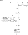
- Fig. 1 is a schematic view of micro-Raman device 100.
- micro-Raman device 100 includes a first laser light source 11, a second laser light source 12, a light source adjustment unit 20, a long-pass filter 41, a long-pass filter 42, a dichroic mirror 43, a dichroic mirror 44, a mirror 45, an objective lens 46, and a Raman spectrometer 50.
- First laser light source 11 generates first laser light L1.
- Second laser light source 12 generates second laser light L2.
- Light source adjustment unit 20 allows one of first laser light L1 and second laser light L2 to pass. When passing through light source adjustment unit 20, one of first laser light L1 and second laser light L2 may have intensity thereof adjusted. Details of light source adjustment unit 20 will be given later.
- First laser light L1 that passed through light source adjustment unit 20 is reflected by long-pass filter 41 and passes through dichroic mirror 43.
- First laser light L1 that passed through dichroic mirror 43 is reflected by mirror 45 and passes through objective lens 46.
- First laser light L1 is thus radiated on a sample S.
- sample S When irradiated with the first laser light, sample S generates first Raman light L3.
- First Raman light L3 generated at sample S passes through objective lens 46 and is reflected by mirror 45.
- First Raman light L3 reflected by mirror 45 sequentially passes through dichroic mirror 43 and long-pass filter 41.
- First Raman light L3 that passed through long-pass filter 41 enters Raman spectrometer 50. Raman measurement using first laser light L1 is thus performed.
- Second laser light L2 that passed through light source adjustment unit 20 is reflected by long-pass filter 42 and passes through dichroic mirror 44.
- Second laser light L2 that passed through dichroic mirror 44 is reflected by mirror 45 and passes through objective lens 46.
- Second laser light L2 is thus radiated on sample S.
- sample S When irradiated with the second laser light, sample S generates second Raman light L4.
- Second Raman light L4 generated at sample S passes through objective lens 46 and is reflected by mirror 45. Second Raman light L4 reflected by mirror 45 sequentially passes through dichroic mirror 44 and long-pass filter 42. Second Raman light L4 that passed through long-pass filter 42 enters Raman spectrometer 50. Raman measurement using second laser light L2 is thus performed.
- Fig. 2 is a schematic side view of light source adjustment unit 20 of micro-Raman device 100.
- light source adjustment unit 20 includes a base 21, a first shaft member 22, a second shaft member 23, a first holder 24, a second holder 25, an ND filter 26, and an ND filter 27.
- First laser light source 11 and second laser light source 12 are disposed on base 21 with a space in between in a first direction DR1.
- First laser light L1 generated by first laser light source 11 and second laser light L2 generated by second laser light source 12 proceed along a second direction DR2 orthogonal to first direction DR1. That is, first laser light L1 and second laser light L2 proceed along second direction DR2 while being separated from each other in first direction DR1.
- First shaft member 22 is attached to base 21.
- First shaft member 22 extends along second direction DR2.
- Second shaft member 23 is attached to base 21.
- Second shaft member 23 extends along second direction DR2.
- First holder 24 is attached to first shaft member 22 in a manner capable of rotating around a first rotation axis A1.
- First rotation axis A1 is parallel to second direction DR2.
- Second holder 25 is attached to second shaft member 23 in a manner capable of rotating around a second rotation axis A2.
- Second rotation axis A2 is parallel to second direction DR2.
- a distance between first rotation axis A1 and first laser light L1 is given as a distance DIS 1.
- a distance between first rotation axis A1 and second laser light L2 is given as a distance DIS2.
- a distance between second rotation axis A2 and first laser light L1 is given as a distance DIS3.
- a distance between second rotation axis A2 and second laser light L2 is given as a distance DIS4.
- Distance DIS2 is greater than distance DIS 1.
- Distance DIS3 is greater than distance DIS4.
- First holder 24 and second holder 25 are formed of a material that does not allow first laser light L1 and second laser light L2 to pass.
- first holder 24 and second holder 25 are formed of a metal material.
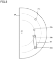
- Fig. 3 is a plan view of first holder 24 of micro-Raman device 100 seen along second direction DR2.
- a planar shape of first holder 24 is a semicircle, for example.
- the planar shape of first holder 24 is not limited to such a shape.
- a through hole 24a, a through hole 24b, a through hole 24c, and a through hole 24d are formed in first holder 24. Through hole 24a, through hole 24b, through hole 24c, and through hole 24d penetrate through first holder 24 in second direction DR2.
- through hole 24a and through hole 24b are arranged on a first arc.
- the first arc is an arc that has first rotation axis A1 at a center, and that has a radius that is equal to distance DIS 1.
- through hole 24c and through hole 24d are arranged on a second arc.
- the second arc is an arc that has first rotation axis A1 at a center, and that has a radius that is equal to distance DIS2.
- a distance between through hole 24b and through hole 24d is equal to or less than a distance between through hole 24b and through hole 24c.
- first holder 24 When first holder 24 is rotated around first rotation axis A1 such that first laser light L1 overlaps with through hole 24a or through hole 24b, through hole 24c and through hole 24d are shifted from second laser light L2.
- first holder 24 is rotated around first rotation axis A1 such that second laser light L2 overlaps with through hole 24c or through hole 24d, through hole 24a and through hole 24b are shifted from first laser light L1. That is, when seen along second direction DR2, through hole 24a and through hole 24b are not on a virtual straight line connecting through hole 24c and first rotation axis A1, and are not on a virtual straight line connecting through hole 24d and first rotation axis A1.
- first laser light L1 when first holder 24 is rotated around first rotation axis A1 such that first laser light L1 overlaps with one of through hole 24a and through hole 24b, second laser light L2 is blocked by first holder 24, and when first holder 24 is rotated around first rotation axis A1 such that second laser light L2 overlaps with one of through hole 24c and through hole 24d, first laser light L1 is blocked by first holder 24.
- Fig. 4 is a plan view of second holder 25 of micro-Raman device 100 seen along second direction DR2.
- a planar shape of second holder 25 is a semicircle, for example.
- the planar shape of second holder 25 is not limited to such a shape.
- a through hole 25a, a through hole 25b, a through hole 25c, and a through hole 25d are formed in second holder 25. Through hole 25a, through hole 25b, through hole 25c, and through hole 25d penetrate through second holder 25 in second direction DR2.
- through hole 25a and through hole 25b are arranged on a third arc.
- the third arc is an arc that has second rotation axis A2 at a center, and that has a radius that is equal to distance DIS3.
- through hole 25c and through hole 25d are arranged on a fourth arc.
- the fourth arc is an arc that has second rotation axis A2 at a center, and that has a radius that is equal to distance DIS4.
- a distance between through hole 25b and through hole 25d is equal to or less than a distance between through hole 25b and through hole 25c.
- ND filter 26 is arranged on first holder 24 in a manner extending over through hole 24b and through hole 24d.
- ND filter 27 is arranged on second holder 25 in a manner extending over through hole 25b and through hole 25d.
- An OD value of ND filter 26 is preferably different from an OD value of ND filter 27.
- an ND (neutral density) filter is an optical filter that reduces intensity of light passing through.
- An OD (optical density) value is a value indicating a transmittance of light through the ND filter. When the OD value is X, the value obtained by dividing intensity of light after passage through the ND filter by intensity of light before passage through the ND filter is 1 ⁇ 10 -X .
- micro-Raman device 100 when first holder 24 is rotated around first rotation axis A1 such that through hole 24a or through hole 24b overlaps with first laser light L1, and second holder 25 is rotated around second rotation axis A2 such that through hole 25a or through hole 25b overlaps with first laser light L1, through hole 24c and through hole 24d are shifted from second laser light L2, and second laser light L2 is blocked by first holder 24.
- first laser light L1 and second laser light L2 are selectively caused to pass through light source adjustment unit 20, and thus, it is not necessary to place one of first laser light source 11 and second laser light source 12 in an off state or to provide a shutter.
- first laser light L1 there are a first pattern of sequentially passing through through hole 24a and through hole 25a, a second pattern of passing through through hole 24b and through hole 25a, a third pattern of passing through through hole 24a and through hole 25b, and a fourth pattern of passing through through hole 24b and through hole 25b.
- first pattern the first laser light L1 passes through light source adjustment unit 20 without being subjected to intensity adjustment
- second pattern first laser light L1 passes through light source adjustment unit 20 by being subjected to intensity adjustment by only ND filter 26.
- first laser light L1 passes through light source adjustment unit 20 by being subjected to intensity adjustment by only ND filter 27, and in the fourth pattern, first laser light L1 passes through light source adjustment unit 20 by being subjected to intensity adjustment by ND filter 26 and ND filter 27. That is, with micro-Raman device 100, four patterns of intensity adjustment may be applied to first laser light L1 by light source adjustment unit 20.
- micro-Raman device 100 four patterns of intensity adjustment may be applied to second laser light L2 by light source adjustment unit 20. Accordingly, with micro-Raman device 100, the size of micro-Raman device 100 may be reduced while allowing intensity adjustment to be finely performed on first laser light L1 and second laser light L2 in a greater number of patterns than the number of the ND filters (that is, two).
- Fig. 5 is a plan view of first holder 24 of micro-Raman device 100 according to a modification seen along the second direction.
- a through hole 24e and a through hole 24f may be further formed in first holder 24.
- Through hole 24e is on the first arc
- through hole 24f is on the second arc.
- the distance between through hole 24b and through hole 24d is equal to or less than the distance between the through hole 24b and through hole 24c and a distance between through hole 24b and through hole 24f
- a distance between through hole 24e and through hole 24f is equal to or less than a distance between through hole 24e and through hole 24c and a distance between through hole 24e and through hole 24d.
- Fig. 6 is a plan view of second holder 25 of micro-Raman device 100 according to the modification seen along the second direction.
- a through hole 25e and a through hole 25f may be further formed in second holder 25.
- Through hole 25e is on the third arc
- through hole 25f is on the fourth arc.
- the distance between through hole 25b and through hole 25d is equal to or less than the distance between through hole 25b and through hole 25c and a distance between through hole 25b and through hole 25f
- a distance between through hole 25e and through hole 25f is equal to or less than a distance between through hole 25e and through hole 25c and a distance between through hole 25e and through hole 25d.
- Light source adjustment unit 20 may further include an ND filter 28 and an ND filter 29.
- ND filter 28 is arranged on first holder 24 in a manner extending over through hole 24e and through hole 24f.
- ND filter 29 is arranged on second holder 25 in a manner extending over through hole 25e and through hole 25f.
- An OD value of ND filter 28 is preferably different from the OD value of ND filter 26.
- An OD value of ND filter 29 is preferably different from the OD value of ND filter 27 and from the OD value of ND filter 28.
- the OD value of ND filter 26 is preferably different from a sum of the OD value of ND filter 28 or the OD value of ND filter 29 and the OD value of ND filter 27.
- the OD value of ND filter 27 is preferably different from a sum of the OD value of ND filter 28 or the OD value of ND filter 29 and the OD value of ND filter 26.
- the OD value of ND filter 28 is preferably different from a sum of the OD value of ND filter 26 or the OD value of ND filter 27 and the OD value of ND filter 29.
- the OD value of ND filter 29 is preferably different from a sum of the OD value of ND filter 26 or the OD value of ND filter 27 and the OD value of ND filter 28.
- intensity of first laser light L1 may be adjusted in nine patterns (a pattern where no intensity adjustment is applied, a pattern where intensity adjustment is applied only by ND filter 26, a pattern where intensity adjustment is applied only by ND filter 27, a pattern where intensity adjustment is applied only by ND filter 28, a pattern where intensity adjustment is applied only by ND filter 29, a pattern where intensity adjustment is applied by ND filter 26 and ND filter 27, a pattern where intensity adjustment is applied by ND filter 26 and ND filter 29, a pattern where intensity adjustment is applied by ND filter 28 and ND filter 27, and a pattern where intensity adjustment is applied by ND filter 28 and ND filter 29), and intensity of second laser light L2 may also be adjusted in nine patterns.
- the number of through holes on the first arc (given as first through holes), the number of through holes on the second arc (given as second through holes), the number of through holes on the third arc (given as third through holes), and the number of through holes on the fourth arc (given as fourth through holes) are not particularly specified.
- the number of first through holes, the number of second through holes, the number of third through holes, and the number of fourth through holes are given as k (where k is a natural number of two or more), the number of ND filters arranged on first holder 24 (given as first ND filters), and the number of ND filters arranged on second holder 25 (given as second ND filters) are given as (k - 1).
- first holder 24 When first holder 24 is rotated around first rotation axis A1 such that one of a plurality of first through holes overlaps with first laser light L1, a plurality of second through holes are all shifted from second laser light L2, and when the first holder 24 is rotated around first rotation axis A1 such that one of the plurality of second through holes overlaps with second laser light L2, the plurality of first through holes are all shifted from first laser light L1.
- Each of a plurality of first ND filters is arranged on first holder 24 in a manner extending over one first through hole and a second through hole that is at a position closest to the one first through hole in question, and each of a plurality of second ND filters is arranged on second holder 25 in a manner extending over one third through hole and a fourth through hole that is at a position closest to the one third through hole in question.
- micro-Raman device according to a second embodiment will be described.
- the micro-Raman device according to the second embodiment will be given as a micro-Raman device 200.
- differences from micro-Raman device 100 will be mainly described, and a redundant description will not be given.
- micro-Raman device 200 A configuration of micro-Raman device 200 will be described below.
- Fig. 7 is a schematic view of micro-Raman device 200.
- micro-Raman device 200 includes first laser light source 11, second laser light source 12, light source adjustment unit 20, long-pass filter 41, long-pass filter 42, dichroic mirror 43, dichroic mirror 44, mirror 45, objective lens 46, and Raman spectrometer 50.
- the configuration of micro-Raman device 200 is the same as the configuration of micro-Raman device 100.
- Fig. 8 is a plan view of first holder 24 of micro-Raman device 200 seen along second direction DR2.
- a through hole 24g and a through hole 24h are further formed in first holder 24.
- Through hole 24g is on the first arc
- through hole 24h is on the second arc.
- Through hole 24g and through hole 24h penetrate through first holder 24 in second direction DR2.
- first holder 24 is rotated around first rotation axis A1 such that through hole 24g overlaps with first laser light L1, through hole 24h overlaps with second laser light L2. That is, when seen along second direction DR2, through hole 24g, through hole 24h, and first rotation axis A1 are on a same virtual straight line.
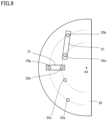
- Fig. 9 is a plan view of second holder 25 of micro-Raman device 200 seen along second direction DR2.
- a through hole 25g and a through hole 25h are further formed in second holder 25.
- Through hole 25g is on the third arc
- through hole 25h is on the fourth arc.
- Through hole 25g and through hole 25h penetrate through second holder 25 in second direction DR2.
- second holder 25 is rotated around second rotation axis A2 such that through hole 25g overlaps with first laser light L1, through hole 25h overlaps with second laser light L2. That is, when seen along second direction DR2, through hole 25g, through hole 25h, and second rotation axis A2 are on a same virtual straight line.
- light source adjustment unit 20 further includes an ND filter 30 and an ND filter 31.
- ND filter 30 is arranged on first holder 24 in a manner extending over through hole 24g and through hole 24h.
- ND filter 31 is arranged on second holder 25 in a manner extending over through hole 25g and through hole 25h.
- An OD value of ND filter 30 is preferably different from the OD value of ND filter 26.
- An OD value of ND filter 31 is preferably different from the OD value of ND filter 27 and from the OD value of ND filter 30.
- the OD value of ND filter 26 is preferably different from a sum of the OD value of ND filter 30 or the OD value of ND filter 31 and the OD value of ND filter 27.
- the OD value of ND filter 27 is preferably different from a sum of the OD value of ND filter 30 or the OD value of ND filter 31 and the OD value of ND filter 26.
- the OD value of ND filter 30 is preferably different from a sum of the OD value of ND filter 26 or the OD value of ND filter 27 and the OD value of ND filter 31.
- the OD value of ND filter 31 is preferably different from a sum of the OD value of ND filter 26 or the OD value of ND filter 27 and the OD value of ND filter 30.
- the configuration of micro-Raman device 200 is different from the configuration of micro-Raman device 100.
- micro-Raman device 200 advantageous effects of micro-Raman device 200 will be described.
- intensity of first laser light L1 may be adjusted in eight patterns (a pattern where no intensity adjustment is applied, a pattern where intensity adjustment is applied only by ND filter 26, a pattern where intensity adjustment is applied only by ND filter 27, a pattern where intensity adjustment is applied only by ND filter 30, a pattern where intensity adjustment is applied only by ND filter 31, a pattern where intensity adjustment is applied by ND filter 26 and ND filter 27, a pattern where intensity adjustment is applied by ND filter 26 and ND filter 30, and a pattern where intensity adjustment is applied by ND filter 30 and ND filter 27), and intensity of second laser light L2 may also be adjusted in eight patterns.
- the number of through holes on the first arc (given as first through holes), the number of through holes on the second arc (given as second through holes), the number of through holes on the third arc (given as third through holes), and the number of through holes on the fourth arc (given as fourth through holes) are not particularly specified.
- the number of first through holes, the number of second through holes, the number of third through holes, and the number of fourth through holes are given as k (where k is a natural number of two or more)
- the number of ND filters arranged on first holder 24 (given as first ND filters)
- the number of ND filters arranged on second holder 25 (given as second ND filters) are given as (k - 1).
- One of a plurality of first through holes will be taken as a fifth through hole.
- One of a plurality of second through holes will be taken as a sixth through hole.
- One of a plurality of third through holes will be taken as a seventh through hole.
- One of a plurality of fourth through holes will be taken as an eighth through hole.
- first holder 24 When first holder 24 is rotated around first rotation axis A1 such that one of the plurality of first through holes other than the fifth through hole overlaps with first laser light L1, the plurality of second through holes are all shifted from second laser light L2, and when first holder 24 is rotated around first rotation axis A1 such that one of the plurality of second through holes other than the sixth through hole overlaps with second laser light L2, the plurality of first through holes are all shifted from first laser light L2.
- One of a plurality of first ND filters will be taken as a third ND filter.
- the third ND filter is arranged on first holder 24 in a manner extending over the fifth through hole and the sixth through hole.
- One of a plurality of second ND filters will be taken as a fourth ND filter.
- the fourth ND filter is arranged on second holder 25 in a manner extending over the seventh through hole and the eighth through hole.
- Each of the plurality of first ND filters other than the third ND filter is arranged on first holder 24 in a manner extending over one first through hole other than the fifth through hole and a second through hole that is other than the sixth through hole and that is at a position closest to the one first through hole in question.
- Each of the plurality of second ND filters other than the fourth ND filter is arranged on second holder 25 in a manner extending over one third through hole other than the seventh through hole and a fourth through hole that is other than the eighth through hole and that is at a position closest to the one third through hole in question.
- a micro-Raman device including:
- micro-Raman device in which an OD value of the second ND filter is different from an OD value of the first ND filter.
- micro-Raman device according to Supplementary Note 1 or 2, further including:
Landscapes
- Physics & Mathematics (AREA)
- Spectroscopy & Molecular Physics (AREA)
- General Physics & Mathematics (AREA)
- Health & Medical Sciences (AREA)
- Life Sciences & Earth Sciences (AREA)
- Chemical & Material Sciences (AREA)
- Analytical Chemistry (AREA)
- Biochemistry (AREA)
- General Health & Medical Sciences (AREA)
- Immunology (AREA)
- Pathology (AREA)
- Nuclear Medicine, Radiotherapy & Molecular Imaging (AREA)
- Investigating, Analyzing Materials By Fluorescence Or Luminescence (AREA)
- Spectrometry And Color Measurement (AREA)
- Microscoopes, Condenser (AREA)
Abstract
A micro-Raman device includes a first laser light source, a second laser light source, a first holder, a second holder, a first ND filter, and a second ND filter. The first laser light source and the second laser light source generate first laser light of a first wavelength and second laser light of a second wavelength, respectively. The second wavelength is different from the first wavelength. The first laser light and the second laser light proceed in a second direction orthogonal to a first direction while being separated from each other in the first direction. The first holder and the second holder are arranged overlapping each other in the second direction.
Description
- This nonprovisional application is based on
Japanese Patent Application No. 2022-171599 filed on October 26, 2022 - The present disclosure relates to a micro-Raman device.
- For example,
Japanese Patent Laying-Open No. 10-90064 Patent Literature 1 includes a pumping laser, a spectrometer, and a detector. With the micro-Raman device described inPatent Literature 1, laser light is radiated on a sample from the pumping laser, and Raman scattered light is generated by the sample. The Raman scattered light is scattered in the spectrometer, and intensity distribution of the Raman scattered light that is scattered is detected by the detector. - A micro-Raman device sometimes includes, as pumping lasers, a plurality of laser light sources (given as a first laser light source and a second laser light source). In the case where the micro-Raman device includes the first laser light source and the second laser light source, laser light from one of the first laser light source and the second laser light source has to be blocked using a shutter or one of the first laser light source and the second laser light source has to be placed in an off state so that the laser light is not radiated on a sample.
- In the case of using a shutter to block laser light from one of the first laser light source and the second laser light source, a size of the micro-Raman device is increased. In the case of placing one of the first laser light source and the second laser light source in an off state, it takes time for output to be stabilized at a time when one of the first laser light source and the second laser light source that is in the off state is placed in an on state again.
- Furthermore, with the micro-Raman device, intensity of laser light to be radiated on a sample has to be finely adjusted. A large number of ND filters are thus required, and the size of the micro-Raman device is increased.
- A micro-Raman device of the present disclosure has been made in view of the above. More specifically, there is provided a micro-Raman device with which laser light from one of a first laser light source and a second laser light source can be blocked without placing the one of the first laser light source and the second laser light source in an off state, and also, intensity of laser light can be finely adjusted while reducing a size of the device.
- The micro-Raman device according to the present disclosure includes a first laser light source, a second laser light source, a first holder, a second holder, a first ND filter, and a second ND filter. The first laser light source and the second laser light source generate first laser light of a first wavelength and second laser light of a second wavelength, respectively. The second wavelength is different from the first wavelength. The first laser light and the second laser light proceed in a second direction orthogonal to a first direction while being separated from each other in the first direction. The first holder and the second holder are arranged overlapping each other in the second direction. The first holder is rotatable around a first rotation axis that is parallel to the second direction. The second holder is rotatable around a second rotation axis that is parallel to the second direction. A first through hole, a second through hole, a third through hole, and a fourth through hole that penetrate through the first holder in the second direction are formed in the first holder. When seen along the second direction, the first through hole and the second through hole are on an arc that has the first rotation axis at a center and that has a radius that is equal to a distance between the first rotation axis and the first laser light. When seen along the second direction, the third through hole and the fourth through hole are on an arc that has the first rotation axis at a center and that has a radius that is equal to a distance between the first rotation axis and the second laser light. A distance between the second through hole and the fourth through hole is smaller than a distance between the second through hole and the third through hole. When the first holder is rotated around the first rotation axis such that one of the first through hole and the second through hole overlaps with the first laser light, the third through hole and the fourth through hole are both shifted from the second laser light. When the first holder is rotated around the first rotation axis such that one of the third through hole and the fourth through hole overlaps with the second laser light, the first through hole and the second through hole are both shifted from the first laser light. A fifth through hole, a sixth through hole, a seventh through hole, and an eighth through hole that penetrate through the second holder in the second direction are formed in the second holder. When seen along the second direction, the fifth through hole and the sixth through hole are on an arc that has the second rotation axis at a center and that has a radius that is equal to a distance between the second rotation axis and the first laser light. When seen along the second direction, the seventh through hole and the eighth through hole are on an arc that has the second rotation axis at a center and that has a radius that is equal to a distance between the second rotation axis and the second laser light. A distance between the sixth through hole and the eighth through hole is smaller than a distance between the sixth through hole and the seventh through hole. When the second holder is rotated around the second rotation axis such that one of the fifth through hole and the sixth through hole overlaps with the first laser light, the seventh through hole and the eighth through hole are both shifted from the second laser light. When the second holder is rotated around the second rotation axis such that one of the seventh through hole and the eighth through hole overlaps with the second laser light, the fifth through hole and the sixth through hole are both shifted from the first laser light. The first ND filter is arranged on the first holder in a manner extending over the second through hole and the fourth through hole. The second ND filter is arranged on the second holder in a manner extending over the sixth through hole and the eighth through hole.
- The foregoing and other objects, features, aspects and advantages of the present invention will become more apparent from the following detailed description of the present invention when taken in conjunction with the accompanying drawings.
-
-
Fig. 1 is a schematic view of amicro-Raman device 100; -
Fig. 2 is a schematic side view of a lightsource adjustment unit 20 ofmicro-Raman device 100; -
Fig. 3 is a plan view of afirst holder 24 ofmicro-Raman device 100 seen along a second direction DR2; -
Fig. 4 is a plan view of asecond holder 25 ofmicro-Raman device 100 seen along second direction DR2; -
Fig. 5 is a plan view offirst holder 24 ofmicro-Raman device 100 according to a modification seen along the second direction; -
Fig. 6 is a plan view ofsecond holder 25 ofmicro-Raman device 100 according to the modification seen along the second direction; -
Fig. 7 is a schematic view of amicro-Raman device 200; -
Fig. 8 is a plan view offirst holder 24 ofmicro-Raman device 200 seen along second direction DR2; and -
Fig. 9 is a plan view ofsecond holder 25 ofmicro-Raman device 200 seen along second direction DR2. - Details of embodiments of the present disclosure will be described with reference to the drawings. In the following drawings, same or corresponding parts are denoted by a same reference sign, and a redundant description is omitted.
- A micro-Raman device according to a first embodiment will be described. The micro-Raman device according to the first embodiment will be given as a
micro-Raman device 100. - A configuration of
micro-Raman device 100 will be described below. -
Fig. 1 is a schematic view ofmicro-Raman device 100. As shown inFig. 1 ,micro-Raman device 100 includes a firstlaser light source 11, a secondlaser light source 12, a lightsource adjustment unit 20, a long-pass filter 41, a long-pass filter 42, adichroic mirror 43, adichroic mirror 44, amirror 45, anobjective lens 46, and a Ramanspectrometer 50. - First
laser light source 11 generates first laser light L1. Secondlaser light source 12 generates second laser light L2. Lightsource adjustment unit 20 allows one of first laser light L1 and second laser light L2 to pass. When passing through lightsource adjustment unit 20, one of first laser light L1 and second laser light L2 may have intensity thereof adjusted. Details of lightsource adjustment unit 20 will be given later. - First laser light L1 that passed through light
source adjustment unit 20 is reflected by long-pass filter 41 and passes throughdichroic mirror 43. First laser light L1 that passed throughdichroic mirror 43 is reflected bymirror 45 and passes throughobjective lens 46. First laser light L1 is thus radiated on a sample S. When irradiated with the first laser light, sample S generates first Raman light L3. - First Raman light L3 generated at sample S passes through
objective lens 46 and is reflected bymirror 45. First Raman light L3 reflected bymirror 45 sequentially passes throughdichroic mirror 43 and long-pass filter 41. First Raman light L3 that passed through long-pass filter 41 entersRaman spectrometer 50. Raman measurement using first laser light L1 is thus performed. - Second laser light L2 that passed through light
source adjustment unit 20 is reflected by long-pass filter 42 and passes throughdichroic mirror 44. Second laser light L2 that passed throughdichroic mirror 44 is reflected bymirror 45 and passes throughobjective lens 46. Second laser light L2 is thus radiated on sample S. When irradiated with the second laser light, sample S generates second Raman light L4. - Second Raman light L4 generated at sample S passes through
objective lens 46 and is reflected bymirror 45. Second Raman light L4 reflected bymirror 45 sequentially passes throughdichroic mirror 44 and long-pass filter 42. Second Raman light L4 that passed through long-pass filter 42 entersRaman spectrometer 50. Raman measurement using second laser light L2 is thus performed. -
Fig. 2 is a schematic side view of lightsource adjustment unit 20 ofmicro-Raman device 100. As shown inFig. 2 , lightsource adjustment unit 20 includes abase 21, afirst shaft member 22, asecond shaft member 23, afirst holder 24, asecond holder 25, anND filter 26, and anND filter 27. - First
laser light source 11 and secondlaser light source 12 are disposed onbase 21 with a space in between in a first direction DR1. First laser light L1 generated by firstlaser light source 11 and second laser light L2 generated by secondlaser light source 12 proceed along a second direction DR2 orthogonal to first direction DR1. That is, first laser light L1 and second laser light L2 proceed along second direction DR2 while being separated from each other in first direction DR1. -
First shaft member 22 is attached tobase 21.First shaft member 22 extends along second direction DR2.Second shaft member 23 is attached tobase 21. -
Second shaft member 23 extends along second direction DR2. -
First holder 24 is attached tofirst shaft member 22 in a manner capable of rotating around a first rotation axis A1. First rotation axis A1 is parallel to second direction DR2.Second holder 25 is attached tosecond shaft member 23 in a manner capable of rotating around a second rotation axis A2. Second rotation axis A2 is parallel to second direction DR2. A distance between first rotation axis A1 and first laser light L1 is given as adistance DIS 1. A distance between first rotation axis A1 and second laser light L2 is given as a distance DIS2. A distance between second rotation axis A2 and first laser light L1 is given as a distance DIS3. A distance between second rotation axis A2 and second laser light L2 is given as a distance DIS4. Distance DIS2 is greater thandistance DIS 1. Distance DIS3 is greater than distance DIS4. -
First holder 24 andsecond holder 25 are formed of a material that does not allow first laser light L1 and second laser light L2 to pass. For example,first holder 24 andsecond holder 25 are formed of a metal material. -
Fig. 3 is a plan view offirst holder 24 ofmicro-Raman device 100 seen along second direction DR2. As shown inFig. 3 , a planar shape offirst holder 24 is a semicircle, for example. However, the planar shape offirst holder 24 is not limited to such a shape. A throughhole 24a, a throughhole 24b, a throughhole 24c, and a throughhole 24d are formed infirst holder 24. Throughhole 24a, throughhole 24b, throughhole 24c, and throughhole 24d penetrate throughfirst holder 24 in second direction DR2. - When seen along second direction DR2, through
hole 24a and throughhole 24b are arranged on a first arc. The first arc is an arc that has first rotation axis A1 at a center, and that has a radius that is equal to distanceDIS 1. When seen along second direction DR2, throughhole 24c and throughhole 24d are arranged on a second arc. The second arc is an arc that has first rotation axis A1 at a center, and that has a radius that is equal to distance DIS2. A distance between throughhole 24b and throughhole 24d is equal to or less than a distance between throughhole 24b and throughhole 24c. - When
first holder 24 is rotated around first rotation axis A1 such that first laser light L1 overlaps with throughhole 24a or throughhole 24b, throughhole 24c and throughhole 24d are shifted from second laser light L2. Whenfirst holder 24 is rotated around first rotation axis A1 such that second laser light L2 overlaps with throughhole 24c or throughhole 24d, throughhole 24a and throughhole 24b are shifted from first laser light L1. That is, when seen along second direction DR2, throughhole 24a and throughhole 24b are not on a virtual straight line connecting throughhole 24c and first rotation axis A1, and are not on a virtual straight line connecting throughhole 24d and first rotation axis A1. - In other words, when
first holder 24 is rotated around first rotation axis A1 such that first laser light L1 overlaps with one of throughhole 24a and throughhole 24b, second laser light L2 is blocked byfirst holder 24, and whenfirst holder 24 is rotated around first rotation axis A1 such that second laser light L2 overlaps with one of throughhole 24c and throughhole 24d, first laser light L1 is blocked byfirst holder 24. -
Fig. 4 is a plan view ofsecond holder 25 ofmicro-Raman device 100 seen along second direction DR2. As shown inFig. 4 , a planar shape ofsecond holder 25 is a semicircle, for example. However, the planar shape ofsecond holder 25 is not limited to such a shape. A throughhole 25a, a throughhole 25b, a throughhole 25c, and a throughhole 25d are formed insecond holder 25. Throughhole 25a, throughhole 25b, throughhole 25c, and throughhole 25d penetrate throughsecond holder 25 in second direction DR2. - When seen along second direction DR2, through
hole 25a and throughhole 25b are arranged on a third arc. The third arc is an arc that has second rotation axis A2 at a center, and that has a radius that is equal to distance DIS3. When seen along second direction DR2, throughhole 25c and throughhole 25d are arranged on a fourth arc. The fourth arc is an arc that has second rotation axis A2 at a center, and that has a radius that is equal to distance DIS4. A distance between throughhole 25b and throughhole 25d is equal to or less than a distance between throughhole 25b and throughhole 25c. - When
second holder 25 is rotated around second rotation axis A2 such that first laser light L1 overlaps with throughhole 25a or throughhole 25b, throughhole 25c and throughhole 25d are shifted from second laser light L2. Whensecond holder 25 is rotated around second rotation axis A2 such that second laser light L2 overlaps with throughhole 25c or throughhole 25d, throughhole 25a and throughhole 25b are shifted from first laser light L1. That is, when seen along second direction DR2, throughhole 25c and throughhole 25d are not on a virtual straight line connecting throughhole 25a and second rotation axis A2, and are not on a virtual straight line connecting throughhole 25b and second rotation axis A2. - In other words, when
second holder 25 is rotated around second rotation axis A2 such that first laser light L1 overlaps with one of throughhole 25a and throughhole 25b, second laser light L2 is blocked bysecond holder 25, and whensecond holder 25 is rotated around second rotation axis A2 such that second laser light L2 overlaps with one of throughhole 25c and throughhole 25d, first laser light L1 is blocked bysecond holder 25. - As shown in
Fig. 3 ,ND filter 26 is arranged onfirst holder 24 in a manner extending over throughhole 24b and throughhole 24d. As shown inFig. 4 ,ND filter 27 is arranged onsecond holder 25 in a manner extending over throughhole 25b and throughhole 25d. An OD value ofND filter 26 is preferably different from an OD value ofND filter 27. Additionally, an ND (neutral density) filter is an optical filter that reduces intensity of light passing through. An OD (optical density) value is a value indicating a transmittance of light through the ND filter. When the OD value is X, the value obtained by dividing intensity of light after passage through the ND filter by intensity of light before passage through the ND filter is 1 × 10-X. - With
micro-Raman device 100, whenfirst holder 24 is rotated around first rotation axis A1 such that throughhole 24a or throughhole 24b overlaps with first laser light L1, andsecond holder 25 is rotated around second rotation axis A2 such that throughhole 25a or throughhole 25b overlaps with first laser light L1, throughhole 24c and throughhole 24d are shifted from second laser light L2, and second laser light L2 is blocked byfirst holder 24. - In the same manner, with
micro-Raman device 100, whenfirst holder 24 is rotated around first rotation axis A1 such that throughhole 24c or throughhole 24d overlaps with second laser light L2, andsecond holder 25 is rotated around second rotation axis A2 such that throughhole 25c or throughhole 25d overlaps with second laser light L2, throughhole 24a and throughhole 24b are shifted from first laser light L1, and first laser light L1 is blocked byfirst holder 24. Accordingly, withmicro-Raman device 100, first laser light L1 and second laser light L2 are selectively caused to pass through lightsource adjustment unit 20, and thus, it is not necessary to place one of firstlaser light source 11 and secondlaser light source 12 in an off state or to provide a shutter. - With respect to first laser light L1, there are a first pattern of sequentially passing through through
hole 24a and throughhole 25a, a second pattern of passing through throughhole 24b and throughhole 25a, a third pattern of passing through throughhole 24a and throughhole 25b, and a fourth pattern of passing through throughhole 24b and throughhole 25b. In the first pattern, the first laser light L1 passes through lightsource adjustment unit 20 without being subjected to intensity adjustment, and in the second pattern, first laser light L1 passes through lightsource adjustment unit 20 by being subjected to intensity adjustment by onlyND filter 26. In the third pattern, first laser light L1 passes through lightsource adjustment unit 20 by being subjected to intensity adjustment by onlyND filter 27, and in the fourth pattern, first laser light L1 passes through lightsource adjustment unit 20 by being subjected to intensity adjustment byND filter 26 andND filter 27. That is, withmicro-Raman device 100, four patterns of intensity adjustment may be applied to first laser light L1 by lightsource adjustment unit 20. - In the same manner, with
micro-Raman device 100, four patterns of intensity adjustment may be applied to second laser light L2 by lightsource adjustment unit 20. Accordingly, withmicro-Raman device 100, the size ofmicro-Raman device 100 may be reduced while allowing intensity adjustment to be finely performed on first laser light L1 and second laser light L2 in a greater number of patterns than the number of the ND filters (that is, two). -
Fig. 5 is a plan view offirst holder 24 ofmicro-Raman device 100 according to a modification seen along the second direction. As shown inFig. 5 , a throughhole 24e and a throughhole 24f may be further formed infirst holder 24. Throughhole 24e is on the first arc, and throughhole 24f is on the second arc. Whenfirst holder 24 is rotated around first rotation axis A1 such that throughhole 24e overlaps with first laser light L1, none of throughhole 24b, throughhole 24d, and throughhole 24f overlaps with second laser light L2. Whenfirst holder 24 is rotated around first rotation axis A1 such that throughhole 24f overlaps with second laser light L2, none of throughhole 24a, throughhole 24c, and throughhole 24e overlaps with first laser light L1. - Additionally, in this example, the distance between through
hole 24b and throughhole 24d is equal to or less than the distance between the throughhole 24b and throughhole 24c and a distance between throughhole 24b and throughhole 24f, and a distance between throughhole 24e and throughhole 24f is equal to or less than a distance between throughhole 24e and throughhole 24c and a distance between throughhole 24e and throughhole 24d. -
Fig. 6 is a plan view ofsecond holder 25 ofmicro-Raman device 100 according to the modification seen along the second direction. As shown inFig. 6 , a throughhole 25e and a throughhole 25f may be further formed insecond holder 25. Throughhole 25e is on the third arc, and throughhole 25f is on the fourth arc. Whensecond holder 25 is rotated around second rotation axis A2 such that throughhole 25e overlaps with first laser light L1, none of throughhole 25b, throughhole 25d, and throughhole 25f overlaps with second laser light L2. Whensecond holder 25 is rotated around second rotation axis A2 such that throughhole 25f overlaps with second laser light L2, none of throughhole 25a, throughhole 25c, and throughhole 25e overlaps with first laser light L1. - Additionally, in this example, the distance between through
hole 25b and throughhole 25d is equal to or less than the distance between throughhole 25b and throughhole 25c and a distance between throughhole 25b and throughhole 25f, and a distance between throughhole 25e and throughhole 25f is equal to or less than a distance between throughhole 25e and throughhole 25c and a distance between throughhole 25e and throughhole 25d. - Light
source adjustment unit 20 may further include anND filter 28 and anND filter 29.ND filter 28 is arranged onfirst holder 24 in a manner extending over throughhole 24e and throughhole 24f.ND filter 29 is arranged onsecond holder 25 in a manner extending over throughhole 25e and throughhole 25f. An OD value ofND filter 28 is preferably different from the OD value ofND filter 26. An OD value ofND filter 29 is preferably different from the OD value ofND filter 27 and from the OD value ofND filter 28. - The OD value of
ND filter 26 is preferably different from a sum of the OD value ofND filter 28 or the OD value ofND filter 29 and the OD value ofND filter 27. The OD value ofND filter 27 is preferably different from a sum of the OD value ofND filter 28 or the OD value ofND filter 29 and the OD value ofND filter 26. The OD value ofND filter 28 is preferably different from a sum of the OD value ofND filter 26 or the OD value ofND filter 27 and the OD value ofND filter 29. The OD value ofND filter 29 is preferably different from a sum of the OD value ofND filter 26 or the OD value ofND filter 27 and the OD value ofND filter 28. - In this example, intensity of first laser light L1 may be adjusted in nine patterns (a pattern where no intensity adjustment is applied, a pattern where intensity adjustment is applied only by
ND filter 26, a pattern where intensity adjustment is applied only byND filter 27, a pattern where intensity adjustment is applied only byND filter 28, a pattern where intensity adjustment is applied only byND filter 29, a pattern where intensity adjustment is applied byND filter 26 andND filter 27, a pattern where intensity adjustment is applied byND filter 26 andND filter 29, a pattern where intensity adjustment is applied byND filter 28 andND filter 27, and a pattern where intensity adjustment is applied byND filter 28 and ND filter 29), and intensity of second laser light L2 may also be adjusted in nine patterns. - As described above, with
micro-Raman device 100, the number of through holes on the first arc (given as first through holes), the number of through holes on the second arc (given as second through holes), the number of through holes on the third arc (given as third through holes), and the number of through holes on the fourth arc (given as fourth through holes) are not particularly specified. When the number of first through holes, the number of second through holes, the number of third through holes, and the number of fourth through holes are given as k (where k is a natural number of two or more), the number of ND filters arranged on first holder 24 (given as first ND filters), and the number of ND filters arranged on second holder 25 (given as second ND filters) are given as (k - 1). - When
first holder 24 is rotated around first rotation axis A1 such that one of a plurality of first through holes overlaps with first laser light L1, a plurality of second through holes are all shifted from second laser light L2, and when thefirst holder 24 is rotated around first rotation axis A1 such that one of the plurality of second through holes overlaps with second laser light L2, the plurality of first through holes are all shifted from first laser light L1. Whensecond holder 25 is rotated around second rotation axis A2 such that one of a plurality of third through holes overlaps with first laser light L1, a plurality of fourth through holes are all shifted from second laser light L2, and whensecond holder 25 is rotated around second rotation axis A2 such that one of the plurality of fourth through holes overlaps with second laser light L2, the plurality of third through holes are all shifted from first laser light L1. - Each of a plurality of first ND filters is arranged on
first holder 24 in a manner extending over one first through hole and a second through hole that is at a position closest to the one first through hole in question, and each of a plurality of second ND filters is arranged onsecond holder 25 in a manner extending over one third through hole and a fourth through hole that is at a position closest to the one third through hole in question. - A micro-Raman device according to a second embodiment will be described. The micro-Raman device according to the second embodiment will be given as a
micro-Raman device 200. Here, differences frommicro-Raman device 100 will be mainly described, and a redundant description will not be given. - A configuration of
micro-Raman device 200 will be described below. -
Fig. 7 is a schematic view ofmicro-Raman device 200. As shown inFig. 7 ,micro-Raman device 200 includes firstlaser light source 11, secondlaser light source 12, lightsource adjustment unit 20, long-pass filter 41, long-pass filter 42,dichroic mirror 43,dichroic mirror 44,mirror 45,objective lens 46, andRaman spectrometer 50. In this regard, the configuration ofmicro-Raman device 200 is the same as the configuration ofmicro-Raman device 100. -
Fig. 8 is a plan view offirst holder 24 ofmicro-Raman device 200 seen along second direction DR2. As shown inFig. 8 , withmicro-Raman device 200, a throughhole 24g and a throughhole 24h are further formed infirst holder 24. Throughhole 24g is on the first arc, and throughhole 24h is on the second arc. Throughhole 24g and throughhole 24h penetrate throughfirst holder 24 in second direction DR2. Whenfirst holder 24 is rotated around first rotation axis A1 such that throughhole 24g overlaps with first laser light L1, throughhole 24h overlaps with second laser light L2. That is, when seen along second direction DR2, throughhole 24g, throughhole 24h, and first rotation axis A1 are on a same virtual straight line. -
Fig. 9 is a plan view ofsecond holder 25 ofmicro-Raman device 200 seen along second direction DR2. As shown inFig. 9 , withmicro-Raman device 200, a throughhole 25g and a throughhole 25h are further formed insecond holder 25. Throughhole 25g is on the third arc, and throughhole 25h is on the fourth arc. Throughhole 25g and throughhole 25h penetrate throughsecond holder 25 in second direction DR2. Whensecond holder 25 is rotated around second rotation axis A2 such that throughhole 25g overlaps with first laser light L1, throughhole 25h overlaps with second laser light L2. That is, when seen along second direction DR2, throughhole 25g, throughhole 25h, and second rotation axis A2 are on a same virtual straight line. - With
micro-Raman device 200, lightsource adjustment unit 20 further includes anND filter 30 and anND filter 31.ND filter 30 is arranged onfirst holder 24 in a manner extending over throughhole 24g and throughhole 24h.ND filter 31 is arranged onsecond holder 25 in a manner extending over throughhole 25g and throughhole 25h. An OD value ofND filter 30 is preferably different from the OD value ofND filter 26. An OD value ofND filter 31 is preferably different from the OD value ofND filter 27 and from the OD value ofND filter 30. - The OD value of
ND filter 26 is preferably different from a sum of the OD value ofND filter 30 or the OD value ofND filter 31 and the OD value ofND filter 27. The OD value ofND filter 27 is preferably different from a sum of the OD value ofND filter 30 or the OD value ofND filter 31 and the OD value ofND filter 26. The OD value ofND filter 30 is preferably different from a sum of the OD value ofND filter 26 or the OD value ofND filter 27 and the OD value ofND filter 31. The OD value ofND filter 31 is preferably different from a sum of the OD value ofND filter 26 or the OD value ofND filter 27 and the OD value ofND filter 30. In this regard, the configuration ofmicro-Raman device 200 is different from the configuration ofmicro-Raman device 100. - In the following, advantageous effects of
micro-Raman device 200 will be described. - With
micro-Raman device 200, intensity of first laser light L1 may be adjusted in eight patterns (a pattern where no intensity adjustment is applied, a pattern where intensity adjustment is applied only byND filter 26, a pattern where intensity adjustment is applied only byND filter 27, a pattern where intensity adjustment is applied only byND filter 30, a pattern where intensity adjustment is applied only byND filter 31, a pattern where intensity adjustment is applied byND filter 26 andND filter 27, a pattern where intensity adjustment is applied byND filter 26 andND filter 30, and a pattern where intensity adjustment is applied byND filter 30 and ND filter 27), and intensity of second laser light L2 may also be adjusted in eight patterns. - Also with
micro-Raman device 200, the number of through holes on the first arc (given as first through holes), the number of through holes on the second arc (given as second through holes), the number of through holes on the third arc (given as third through holes), and the number of through holes on the fourth arc (given as fourth through holes) are not particularly specified. When the number of first through holes, the number of second through holes, the number of third through holes, and the number of fourth through holes are given as k (where k is a natural number of two or more), the number of ND filters arranged on first holder 24 (given as first ND filters), and the number of ND filters arranged on second holder 25 (given as second ND filters) are given as (k - 1). - One of a plurality of first through holes will be taken as a fifth through hole. One of a plurality of second through holes will be taken as a sixth through hole. One of a plurality of third through holes will be taken as a seventh through hole. One of a plurality of fourth through holes will be taken as an eighth through hole. When the
first holder 24 is rotated around first rotation axis A1 such that the fifth through hole overlaps with first laser light L1, the sixth through hole overlaps with second laser light L2, and whensecond holder 25 is rotated around second rotation axis A2 such that the seventh through hole overlaps with first laser light L1, the eighth through hole overlaps with second laser light L2. - When
first holder 24 is rotated around first rotation axis A1 such that one of the plurality of first through holes other than the fifth through hole overlaps with first laser light L1, the plurality of second through holes are all shifted from second laser light L2, and whenfirst holder 24 is rotated around first rotation axis A1 such that one of the plurality of second through holes other than the sixth through hole overlaps with second laser light L2, the plurality of first through holes are all shifted from first laser light L2. Whensecond holder 25 is rotated around second rotation axis A2 such that one of the plurality of third through holes other than the seventh through hole overlaps with first laser light L1, the plurality of fourth through holes are all shifted from second laser light L2, and whensecond holder 25 is rotated around second rotation axis A2 such that one of the plurality of fourth through holes other than the eighth through hole overlaps with second laser light L2, the plurality of third through holes are all shifted from first laser light L1. - One of a plurality of first ND filters will be taken as a third ND filter. The third ND filter is arranged on
first holder 24 in a manner extending over the fifth through hole and the sixth through hole. One of a plurality of second ND filters will be taken as a fourth ND filter. The fourth ND filter is arranged onsecond holder 25 in a manner extending over the seventh through hole and the eighth through hole. Each of the plurality of first ND filters other than the third ND filter is arranged onfirst holder 24 in a manner extending over one first through hole other than the fifth through hole and a second through hole that is other than the sixth through hole and that is at a position closest to the one first through hole in question. Each of the plurality of second ND filters other than the fourth ND filter is arranged onsecond holder 25 in a manner extending over one third through hole other than the seventh through hole and a fourth through hole that is other than the eighth through hole and that is at a position closest to the one third through hole in question. - The embodiments described above include the following configurations.
- A micro-Raman device including:
- a first laser light source;
- a second laser light source;
- a first holder;
- a second holder;
- a first ND filter; and
- a second ND filter, in which
- the first laser light source and the second laser light source generate first laser light of a first wavelength and second laser light of a second wavelength, respectively,
- the second wavelength is different from the first wavelength,
- the first laser light and the second laser light proceed in a second direction orthogonal to a first direction while being separated from each other in the first direction,
- the first holder and the second holder are arranged overlapping each other in the second direction,
- the first holder is rotatable around a first rotation axis that is parallel to the second direction,
- the second holder is rotatable around a second rotation axis that is parallel to the second direction,
- a first through hole, a second through hole, a third through hole, and a fourth through hole that penetrate through the first holder in the second direction are formed in the first holder,
- when seen along the second direction, the first through hole and the second through hole are on an arc that has the first rotation axis at a center and that has a radius that is equal to a distance between the first rotation axis and the first laser light,
- when seen along the second direction, the third through hole and the fourth through hole are on an arc that has the first rotation axis at a center and that has a radius that is equal to a distance between the first rotation axis and the second laser light,
- a distance between the second through hole and the fourth through hole is smaller than a distance between the second through hole and the third through hole,
- when the first holder is rotated around the first rotation axis such that one of the first through hole and the second through hole overlaps with the first laser light, the third through hole and the fourth through hole are both shifted from the second laser light,
- when the first holder is rotated around the first rotation axis such that one of the third through hole and the fourth through hole overlaps with the second laser light, the first through hole and the second through hole are both shifted from the first laser light,
- a fifth through hole, a sixth through hole, a seventh through hole, and an eighth through hole that penetrate through the second holder in the second direction are formed in the second holder,
- when seen along the second direction, the fifth through hole and the sixth through hole are on an arc that has the second rotation axis at a center and that has a radius that is equal to a distance between the second rotation axis and the first laser light,
- when seen along the second direction, the seventh through hole and the eighth through hole are on an arc that has the second rotation axis at a center and that has a radius that is equal to a distance between the second rotation axis and the second laser light,
- a distance between the sixth through hole and the eighth through hole is smaller than a distance between the sixth through hole and the seventh through hole,
- when the second holder is rotated around the second rotation axis such that one of the fifth through hole and the sixth through hole overlaps with the first laser light, the seventh through hole and the eighth through hole are both shifted from the second laser light,
- when the second holder is rotated around the second rotation axis such that one of the seventh through hole and the eighth through hole overlaps with the second laser light, the fifth through hole and the sixth through hole are both shifted from the first laser light,
- the first ND filter is arranged on the first holder in a manner extending over the second through hole and the fourth through hole, and
- the second ND filter is arranged on the second holder in a manner extending over the sixth through hole and the eighth through hole.
- The micro-Raman device according to
Supplementary Note 1, in which an OD value of the second ND filter is different from an OD value of the first ND filter. - The micro-Raman device according to
Supplementary Note 1 or 2, further including: - a third ND filter; and
- a fourth ND filter, in which
- a ninth through hole and a tenth through hole that penetrate through the first holder in the second direction are further formed in the first holder,
- when the first holder is rotated around the first rotation axis such that the ninth through hole overlaps with the first laser light, the tenth through hole overlaps with the second laser light,
- an eleventh through hole and a twelfth through hole that penetrate through the second holder in the second direction are further formed in the second holder,
- when the second holder is rotated around the second rotation axis such that the eleventh through hole overlaps with the first laser light, the twelfth through hole overlaps with the second laser light,
- the third ND filter is arranged on the first holder in a manner extending over the ninth through hole and the tenth through hole, and
- the fourth ND filter is arranged on the second holder in a manner extending over the eleventh through hole and the twelfth through hole.
- The micro-Raman device according to Supplementary Note 3, in which
- an OD value of the third ND filter is different from the OD value of the first ND filter, and
- an OD value of the fourth ND filter is different from the OD value of the second ND filter and from the OD value of the third ND filter.
- Although embodiments of the present invention have been described, the embodiments disclosed herein are considered in all respects as illustrative and not restrictive. The scope of the present invention is indicated by the appended claims, and all changes within the meaning and scope equivalent to the scope of the claims are intended to be included.
Claims (4)
- A micro-Raman device comprising:a first laser light source;a second laser light source;a first holder;a second holder;a first ND filter; anda second ND filter, whereinthe first laser light source and the second laser light source generate first laser light of a first wavelength and second laser light of a second wavelength, respectively,the second wavelength is different from the first wavelength,the first laser light and the second laser light proceed in a second direction orthogonal to a first direction while being separated from each other in the first direction,the first holder and the second holder are arranged overlapping each other in the second direction,the first holder is rotatable around a first rotation axis that is parallel to the second direction,the second holder is rotatable around a second rotation axis that is parallel to the second direction,a first through hole, a second through hole, a third through hole, and a fourth through hole that penetrate through the first holder in the second direction are formed in the first holder,when seen along the second direction, the first through hole and the second through hole are on an arc that has the first rotation axis at a center and that has a radius that is equal to a distance between the first rotation axis and the first laser light,when seen along the second direction, the third through hole and the fourth through hole are on an arc that has the first rotation axis at a center and that has a radius that is equal to a distance between the first rotation axis and the second laser light,a distance between the second through hole and the fourth through hole is smaller than a distance between the second through hole and the third through hole,when the first holder is rotated around the first rotation axis such that one of the first through hole and the second through hole overlaps with the first laser light, the third through hole and the fourth through hole are both shifted from the second laser light,when the first holder is rotated around the first rotation axis such that one of the third through hole and the fourth through hole overlaps with the second laser light, the first through hole and the second through hole are both shifted from the first laser light,a fifth through hole, a sixth through hole, a seventh through hole, and an eighth through hole that penetrate through the second holder in the second direction are formed in the second holder,when seen along the second direction, the fifth through hole and the sixth through hole are on an arc that has the second rotation axis at a center and that has a radius that is equal to a distance between the second rotation axis and the first laser light,when seen along the second direction, the seventh through hole and the eighth through hole are on an arc that has the second rotation axis at a center and that has a radius that is equal to a distance between the second rotation axis and the second laser light,a distance between the sixth through hole and the eighth through hole is smaller than a distance between the sixth through hole and the seventh through hole,when the second holder is rotated around the second rotation axis such that one of the fifth through hole and the sixth through hole overlaps with the first laser light, the seventh through hole and the eighth through hole are both shifted from the second laser light,when the second holder is rotated around the second rotation axis such that one of the seventh through hole and the eighth through hole overlaps with the second laser light, the fifth through hole and the sixth through hole are both shifted from the first laser light,the first ND filter is arranged on the first holder in a manner extending over the second through hole and the fourth through hole, andthe second ND filter is arranged on the second holder in a manner extending over the sixth through hole and the eighth through hole.
- The micro-Raman device according to claim 1, wherein an OD value of the second ND filter is different from an OD value of the first ND filter.
- The micro-Raman device according to claim 1, further comprising:a third ND filter; anda fourth ND filter, whereina ninth through hole and a tenth through hole that penetrate through the first holder in the second direction are further formed in the first holder,when the first holder is rotated around the first rotation axis such that the ninth through hole overlaps with the first laser light, the tenth through hole overlaps with the second laser light,an eleventh through hole and a twelfth through hole that penetrate through the second holder in the second direction are further formed in the second holder,when the second holder is rotated around the second rotation axis such that the eleventh through hole overlaps with the first laser light, the twelfth through hole overlaps with the second laser light,the third ND filter is arranged on the first holder in a manner extending over the ninth through hole and the tenth through hole, andthe fourth ND filter is arranged on the second holder in a manner extending over the eleventh through hole and the twelfth through hole.
- The micro-Raman device according to claim 3, whereinan OD value of the third ND filter is different from the OD value of the first ND filter, andan OD value of the fourth ND filter is different from the OD value of the second ND filter and from the OD value of the third ND filter.
Applications Claiming Priority (1)
| Application Number | Priority Date | Filing Date | Title |
|---|---|---|---|
| JP2022171599A JP2024063550A (en) | 2022-10-26 | 2022-10-26 | Raman Microscope |
Publications (1)
| Publication Number | Publication Date |
|---|---|
| EP4361584A1 true EP4361584A1 (en) | 2024-05-01 |
Family
ID=88511265
Family Applications (1)
| Application Number | Title | Priority Date | Filing Date |
|---|---|---|---|
| EP23205765.3A Withdrawn EP4361584A1 (en) | 2022-10-26 | 2023-10-25 | Micro-raman device |
Country Status (4)
| Country | Link |
|---|---|
| US (1) | US12372472B2 (en) |
| EP (1) | EP4361584A1 (en) |
| JP (1) | JP2024063550A (en) |
| CN (1) | CN117929346A (en) |
Citations (4)
| Publication number | Priority date | Publication date | Assignee | Title |
|---|---|---|---|---|
| US4158505A (en) * | 1976-12-27 | 1979-06-19 | International Business Machines Corporation | Spectrum analyzing system with photodiode array |
| JPH1090064A (en) | 1996-09-12 | 1998-04-10 | Fujitsu Ltd | Raman microscope |
| US20080117421A1 (en) * | 2005-07-15 | 2008-05-22 | Olympus Corporation | Optical measurement apparatus |
| US20120190034A1 (en) * | 2009-08-06 | 2012-07-26 | Universal Bio Research Co., Ltd. | Optical fiber measurement device and measurement method using same |
Family Cites Families (7)
| Publication number | Priority date | Publication date | Assignee | Title |
|---|---|---|---|---|
| US6621574B1 (en) * | 2000-05-25 | 2003-09-16 | Inphotonics, Inc. | Dual function safety and calibration accessory for raman and other spectroscopic sampling |
| GB0510497D0 (en) * | 2004-08-04 | 2005-06-29 | Horiba Ltd | Substrate examining device |
| US7764424B2 (en) * | 2006-05-15 | 2010-07-27 | Olympus Corporation | Light source apparatus and microscope apparatus |
| GB2560893A (en) * | 2017-03-23 | 2018-10-03 | Sumitomo Chemical Co | Raman spectroscopy |
| CN113984202B (en) * | 2020-07-27 | 2024-11-19 | 深圳中科飞测科技股份有限公司 | Filter wheel device, optical detection system and working method of filter wheel device |
| CN114755838B (en) * | 2022-04-01 | 2024-04-05 | 北京半导体专用设备研究所(中国电子科技集团公司第四十五研究所) | Optical alignment system |
| GB2620627B (en) * | 2022-07-14 | 2025-02-05 | Andor Tech Limited | Raman spectroscopy apparatus and method |
-
2022
- 2022-10-26 JP JP2022171599A patent/JP2024063550A/en active Pending
-
2023
- 2023-10-23 US US18/382,930 patent/US12372472B2/en active Active
- 2023-10-24 CN CN202311386570.4A patent/CN117929346A/en active Pending
- 2023-10-25 EP EP23205765.3A patent/EP4361584A1/en not_active Withdrawn
Patent Citations (4)
| Publication number | Priority date | Publication date | Assignee | Title |
|---|---|---|---|---|
| US4158505A (en) * | 1976-12-27 | 1979-06-19 | International Business Machines Corporation | Spectrum analyzing system with photodiode array |
| JPH1090064A (en) | 1996-09-12 | 1998-04-10 | Fujitsu Ltd | Raman microscope |
| US20080117421A1 (en) * | 2005-07-15 | 2008-05-22 | Olympus Corporation | Optical measurement apparatus |
| US20120190034A1 (en) * | 2009-08-06 | 2012-07-26 | Universal Bio Research Co., Ltd. | Optical fiber measurement device and measurement method using same |
Also Published As
| Publication number | Publication date |
|---|---|
| US12372472B2 (en) | 2025-07-29 |
| US20240142380A1 (en) | 2024-05-02 |
| CN117929346A (en) | 2024-04-26 |
| JP2024063550A (en) | 2024-05-13 |
Similar Documents
| Publication | Publication Date | Title |
|---|---|---|
| JP3949160B2 (en) | Device for selecting and detecting at least two spectral ranges of a luminous flux | |
| Leach et al. | Observation of the vortex structure of a non-integer vortex beam | |
| Ching et al. | The Large Area Radio Galaxy Evolution Spectroscopic Survey (LARGESS): survey design, data catalogue and GAMA/WiggleZ spectroscopy | |
| CN102713504B (en) | Surface shape measurement method and surface shape measurement device | |
| CN115307735A (en) | System and method for metrology with layer specific illumination spectra | |
| Butler et al. | Multi-dimensional spectral single molecule localization microscopy | |
| CN107851589A (en) | It is used for the method and device that spot suppresses in laser dark-field system | |
| Kuzio de Naray et al. | Searching for non-axisymmetries in NGC 6503: a weak end-on bar | |
| Nucita et al. | Discovery of a bright microlensing event with planetary features towards the Taurus region: a super-Earth planet | |
| US10648856B2 (en) | Method and system for measuring beam quality of a laser beam | |
| EP4361584A1 (en) | Micro-raman device | |
| US7224458B2 (en) | Phase-shifting test mask patterns for characterizing illumination polarization balance in image forming optical systems | |
| Kruczek et al. | High efficiency echelle gratings for the far ultraviolet | |
| Spiga et al. | Optical simulations for the laboratory-based expanded and collimated x-ray beam facility BEaTriX | |
| JP2001183233A (en) | Spectrometer and spectral method | |
| EP2098849B1 (en) | Test apparatus usable to measure stray light in electro-optical apparatuses | |
| Hard et al. | Phase-randomized laser illumination for microscopy | |
| NL2030071B1 (en) | Method for determining an image quality of an imaging system, device | |
| WO2006003867A3 (en) | Microscope observation method, microscope, differentiation interference microscope, phase difference microscope, interference microscope, image processing method, and image processing device | |
| Camper et al. | Two-dimensional phase cartography for high-harmonic spectroscopy | |
| Dezfouli et al. | Higher-order topological charge detection using off-axis parabolic mirror | |
| Canestrari et al. | Wavefront propagation simulations for a UV/soft X-ray beamline: Electron Spectro-Microscopy beamline at NSLS-II | |
| CN104316185B (en) | Method and apparatus that are a kind of while monitoring laser spectrum and spectral power distribution | |
| JP2012127855A (en) | Spectroscopic device | |
| CN106969835A (en) | A kind of two grades applied to spectral instrument and the removing method of Advanced Diffraction spectrum |
Legal Events
| Date | Code | Title | Description |
|---|---|---|---|
| PUAI | Public reference made under article 153(3) epc to a published international application that has entered the european phase |
Free format text: ORIGINAL CODE: 0009012 |
|
| STAA | Information on the status of an ep patent application or granted ep patent |
Free format text: STATUS: REQUEST FOR EXAMINATION WAS MADE |
|
| 17P | Request for examination filed |
Effective date: 20231025 |
|
| AK | Designated contracting states |
Kind code of ref document: A1 Designated state(s): AL AT BE BG CH CY CZ DE DK EE ES FI FR GB GR HR HU IE IS IT LI LT LU LV MC ME MK MT NL NO PL PT RO RS SE SI SK SM TR |
|
| STAA | Information on the status of an ep patent application or granted ep patent |
Free format text: STATUS: THE APPLICATION IS DEEMED TO BE WITHDRAWN |
|
| 18D | Application deemed to be withdrawn |
Effective date: 20241105 |