EP4361540A1 - Refrigerator - Google Patents
Refrigerator Download PDFInfo
- Publication number
- EP4361540A1 EP4361540A1 EP22827656.4A EP22827656A EP4361540A1 EP 4361540 A1 EP4361540 A1 EP 4361540A1 EP 22827656 A EP22827656 A EP 22827656A EP 4361540 A1 EP4361540 A1 EP 4361540A1
- Authority
- EP
- European Patent Office
- Prior art keywords
- water
- door
- dispenser
- accommodating area
- water cup
- Prior art date
- Legal status (The legal status is an assumption and is not a legal conclusion. Google has not performed a legal analysis and makes no representation as to the accuracy of the status listed.)
- Pending
Links
- XLYOFNOQVPJJNP-UHFFFAOYSA-N water Substances O XLYOFNOQVPJJNP-UHFFFAOYSA-N 0.000 claims abstract description 229
- 241000190070 Sarracenia purpurea Species 0.000 claims abstract description 132
- 238000005057 refrigeration Methods 0.000 claims abstract description 21
- 230000008014 freezing Effects 0.000 claims abstract description 12
- 238000007710 freezing Methods 0.000 claims abstract description 12
- 239000011810 insulating material Substances 0.000 claims abstract description 5
- 238000003860 storage Methods 0.000 claims abstract description 5
- 238000005192 partition Methods 0.000 claims description 14
- 230000009977 dual effect Effects 0.000 claims description 5
- 238000000034 method Methods 0.000 description 8
- 241001122767 Theaceae Species 0.000 description 7
- 230000001846 repelling effect Effects 0.000 description 5
- 238000004519 manufacturing process Methods 0.000 description 4
- 239000008400 supply water Substances 0.000 description 4
- 238000010586 diagram Methods 0.000 description 3
- 230000002708 enhancing effect Effects 0.000 description 3
- 239000006260 foam Substances 0.000 description 3
- 238000009434 installation Methods 0.000 description 3
- 238000011900 installation process Methods 0.000 description 3
- 238000007789 sealing Methods 0.000 description 3
- 238000005429 filling process Methods 0.000 description 2
- 239000006261 foam material Substances 0.000 description 2
- 239000000463 material Substances 0.000 description 2
- 239000000243 solution Substances 0.000 description 2
- 229920001875 Ebonite Polymers 0.000 description 1
- 238000009825 accumulation Methods 0.000 description 1
- 238000011109 contamination Methods 0.000 description 1
- 238000012938 design process Methods 0.000 description 1
- 230000003467 diminishing effect Effects 0.000 description 1
- 238000009826 distribution Methods 0.000 description 1
- 238000002347 injection Methods 0.000 description 1
- 239000007924 injection Substances 0.000 description 1
- 238000009413 insulation Methods 0.000 description 1
- 239000007788 liquid Substances 0.000 description 1
- 239000000203 mixture Substances 0.000 description 1
- 238000000465 moulding Methods 0.000 description 1
- 238000004904 shortening Methods 0.000 description 1
- 238000003466 welding Methods 0.000 description 1
Images





Classifications
-
- F—MECHANICAL ENGINEERING; LIGHTING; HEATING; WEAPONS; BLASTING
- F25—REFRIGERATION OR COOLING; COMBINED HEATING AND REFRIGERATION SYSTEMS; HEAT PUMP SYSTEMS; MANUFACTURE OR STORAGE OF ICE; LIQUEFACTION SOLIDIFICATION OF GASES
- F25D—REFRIGERATORS; COLD ROOMS; ICE-BOXES; COOLING OR FREEZING APPARATUS NOT OTHERWISE PROVIDED FOR
- F25D23/00—General constructional features
- F25D23/12—Arrangements of compartments additional to cooling compartments; Combinations of refrigerators with other equipment, e.g. stove
- F25D23/126—Water cooler
-
- F—MECHANICAL ENGINEERING; LIGHTING; HEATING; WEAPONS; BLASTING
- F25—REFRIGERATION OR COOLING; COMBINED HEATING AND REFRIGERATION SYSTEMS; HEAT PUMP SYSTEMS; MANUFACTURE OR STORAGE OF ICE; LIQUEFACTION SOLIDIFICATION OF GASES
- F25D—REFRIGERATORS; COLD ROOMS; ICE-BOXES; COOLING OR FREEZING APPARATUS NOT OTHERWISE PROVIDED FOR
- F25D11/00—Self-contained movable devices, e.g. domestic refrigerators
-
- F—MECHANICAL ENGINEERING; LIGHTING; HEATING; WEAPONS; BLASTING
- F25—REFRIGERATION OR COOLING; COMBINED HEATING AND REFRIGERATION SYSTEMS; HEAT PUMP SYSTEMS; MANUFACTURE OR STORAGE OF ICE; LIQUEFACTION SOLIDIFICATION OF GASES
- F25D—REFRIGERATORS; COLD ROOMS; ICE-BOXES; COOLING OR FREEZING APPARATUS NOT OTHERWISE PROVIDED FOR
- F25D23/00—General constructional features
- F25D23/02—Doors; Covers
- F25D23/028—Details
-
- F—MECHANICAL ENGINEERING; LIGHTING; HEATING; WEAPONS; BLASTING
- F25—REFRIGERATION OR COOLING; COMBINED HEATING AND REFRIGERATION SYSTEMS; HEAT PUMP SYSTEMS; MANUFACTURE OR STORAGE OF ICE; LIQUEFACTION SOLIDIFICATION OF GASES
- F25D—REFRIGERATORS; COLD ROOMS; ICE-BOXES; COOLING OR FREEZING APPARATUS NOT OTHERWISE PROVIDED FOR
- F25D23/00—General constructional features
- F25D23/02—Doors; Covers
- F25D23/04—Doors; Covers with special compartments, e.g. butter conditioners
-
- F—MECHANICAL ENGINEERING; LIGHTING; HEATING; WEAPONS; BLASTING
- F25—REFRIGERATION OR COOLING; COMBINED HEATING AND REFRIGERATION SYSTEMS; HEAT PUMP SYSTEMS; MANUFACTURE OR STORAGE OF ICE; LIQUEFACTION SOLIDIFICATION OF GASES
- F25D—REFRIGERATORS; COLD ROOMS; ICE-BOXES; COOLING OR FREEZING APPARATUS NOT OTHERWISE PROVIDED FOR
- F25D2323/00—General constructional features not provided for in other groups of this subclass
- F25D2323/122—General constructional features not provided for in other groups of this subclass the refrigerator is characterised by a water tank for the water/ice dispenser
Definitions
- the present invention relates to the field of home appliances, particularly to a type of refrigerator.
- refrigerators have become an indispensable home appliance.
- some refrigerators are equipped with a water tank and a water supply component that automatically supplies water to the tank.
- a dispenser connected to the water tank is installed on the door of the refrigerator, allowing users to obtain water from the tank via the dispenser.
- using the dispenser to dispense water is slow and cannot meet the demand for large quantities of water. Installing two water tanks inside the refrigerator would occupy too much space. Additionally, the room-temperature water in the pipelines may mix with the cold water in the tank inside the refrigerator, affecting the taste of the chilled water.
- the present invention provides a refrigerator with a compact structure, featuring both a dispenser water tank and a water cup on its door.
- an embodiment of the present invention provides a refrigerator comprising a cabinet and a door for opening and closing the cabinet, where the storage space defined by the cabinet comprises a refrigerating compartment and a freezing compartment; the door comprises a refrigerating door for opening and closing the refrigerating compartment and a freezing door for the freezing compartment; the door comprises a door shell and a door liner, with insulating material filled between the door shell and the door liner; a dispenser is provided on the door ; characterized in that, a water tank bracket is provided on the door liner of the refrigeration door, the water tank bracket comprises a dispenser water tank accommodating area and a water cup accommodating area set along the width direction of the refrigeration door, a dispenser water tank connected to the dispenser is provided in the dispenser water tank accommodating area, and a removable water cup is placed in the water cup accommodating area.
- the refrigerating door comprises a hinge side connected to the cabinet and an opening side opposite the hinge side
- the dispenser water tank accommodating area is close to the hinge side
- the water cup accommodating area is close to the opening side
- the water cup accommodating area has an opening end facing the opening side
- the direction of removing the water cup is parallel to the width direction of the door.
- the dispenser water tank is cylindrical and vertically installed in the dispenser water tank accommodating area
- the water cup is rectangular
- the length direction of the water cup is parallel to the width direction of the door.
- a water supply unit an aperture for passing pipes corresponding to the dispenser water tank accommodating area is provided on the inner side of the refrigerating door
- the water supply unit comprises a first water supply pipe connected to an external water source, the first water supply pipe enters the refrigerating door from the door shaft of the refrigerating door and exits through the aperture into the dispenser water tank accommodating area, the first water supply pipe is connected to the water inlet of the dispenser water tank, a second water supply pipe is also provided on the inner side of the refrigeration door, one end of the second water supply pipe is connected to the water outlet of the dispenser, and the other end passes through the aperture into the dispenser water tank accommodating area and is connected to the water outlet of the dispenser water tank.
- the door liner towards the door shell side is connected to a water pipe bracket
- the water pipe bracket has a pipe guiding cavity, an opening corresponding to the pipe guiding cavity is provided on the door liner, and an opening is provided on the wall of the pipe guiding cavity.
- the water tank bracket further comprises a pipeline accommodating area provided above the water cup accommodating area, a valve with one inlet and two outlets is installed in the pipeline accommodating area, the water inlet of the valve is connected to the first water supply pipe, one water outlet of the valve is connected to the water inlet of the dispenser water tank through a third water supply pipe, and the other water outlet supplies water to the water cup.
- the dual outlet valve is installed on the partition wall, the top of the water cup is provided with a water inlet, an opening corresponding to the water inlet of the water cup is provided on the partition wall, and the other water outlet of the dual outlet valve has a water nozzle provided in the opening.
- the bottom wall of the water cup accommodating area is provided with a water cup accommodating groove
- the water cup accommodating groove is provided with an overflow groove and a drainage groove connecting the overflow groove with the rear wall of the water cup accommodating area
- an overflow sensor is provided between the rear wall of the water cup accommodating area and the door liner, and the position of the overflow sensor corresponds to the position of the drainage groove.
- the bottom wall of the water cup accommodating area is provided with a water cup accommodating groove
- the bottom of the water cup is placed in the water cup accommodating groove
- the water cup accommodating groove has a front wall and a rear wall parallel to the width direction of the refrigeration door, and two side walls connecting the front and rear walls, the side wall near the opening end is arc-shaped and lower than the front and rear walls of the water cup accommodating groove, the front and rear walls of the water cup accommodating groove near the opening end are sloped, forming a trumpet shape expanding towards the opening end.
- top wall of the water cup accommodating area is provided with an anti-tilt rib, and the anti-tilt rib is arc-shaped and positioned away from the opening end.
- the refrigerator provided by this invention comprises a refrigerator door provide with a water tank bracket, a dispenser water tank and a water cup provided in the bracket and arranged in the width direction of the door.
- the refrigerator provided by this invention provides a compact structure with a large storage capacity. Users can choose to obtain cold water from the dispenser water tank via the dispenser, or directly open the refrigeration door to take out the water cup for cold water, catering to diverse needs and enhancing user experience.
- an embodiment of the invention provides a refrigerator, comprising a cabinet and a door used to open and close the cabinet.
- the door can be pivotally connected to the cabinet via a hinge.
- the storage space defined by the cabinet can comprise a refrigerating compartment and a freezing compartment.
- the door comprises a refrigerating door 100 for opening and closing the refrigerating compartment and a freezing door for opening and closing the freezing compartment.
- the door comprises a door shell 110 and a door liner 120, with insulating material filled between the door shell 110 and the door liner 120 to prevent the leakage of cold air from the cabinet.
- the insulating material can be foam material.
- a dispenser 130 can also be provided on the door.
- the refrigerator can have a water tank and an ice-making device provided inside, allowing users to take out ice cubes and water stored in the refrigerator through the dispenser 130 without opening the door.
- the door liner 120 of the refrigeration door 100 is provided with a water tank bracket 220.
- the water tank bracket 220 comprises a dispenser water tank accommodating area 210 and a water cup accommodating area 220, both arranged along the width direction of the refrigerating door 100.
- a dispenser water tank 300 connected to the dispenser 130 is provided in the dispenser water tank accommodating area 210, and a removable water cup 400 is placed in the water cup accommodating area 220.
- users can take water from the dispenser water tank 300 through the dispenser 130. Users can also directly remove the water cup 400 from the water tank bracket 220 to use cold water.
- both the dispenser water tank 300 and the water cup 400 provided on the refrigerating door 100 it meets various water using needs of users.
- Directly providing the water tank bracket 220 on the refrigeration door 100, and centralizing the dispenser water tank 300 and water cup 400 within the water tank bracket 220, where they are arranged along the door width direction, does not affect the installation of the shelf 190 on the refrigeration door 100.
- the overall structure is compact, and the space utilization rate is high.
- the dispenser 130 is provided on the refrigerating door 100, and the water tank bracket 220 is provided behind the dispenser 130.
- the door shell 110 of the refrigerating door 100 can have a dispenser housing that recesses towards the door liner 120 side.
- the door liner 120 corresponding to the position of dispenser 130 protrudes towards the cabinet of the refrigerator to ensure enough foam material is filled between the dispenser housing and the door liner 120, ensuring insulation.
- the water tank bracket 220 is provided behind the dispenser 130, making full use of the space on the door corresponding to the location of the dispenser 130.
- the refrigerating door 100 comprises a hinge side 140 connected to the cabinet and an opening side 150 opposite to the hinge side 140.
- the dispenser water tank accommodating area 210 is near the hinge side 140, and the water cup accommodating area 220 is near the opening side 150.
- the water cup accommodating area 220 has an opening end 221 facing the opening side 150, and the remove direction of the water cup 400 is parallel to the width direction of the refrigeration door 100.
- the dispenser water tank 300 is cylindrical and vertically installed in the dispenser water tank accommodating area 210.
- the water cup 400 is rectangular, and its length direction is parallel to the width direction of the door.
- the water tank bracket 220 can be rectangular, with a partition between the dispenser water tank accommodating area 210 and the water cup accommodating area 220.
- the interior accommodating space of the water cup accommodating area 220 can be rectangular, and the wall of the water cup accommodating area 220 facing the cabinet can be transparent, allowing users to directly observe the water level inside the water cup 400.
- the water cup 400 can have a handle 411 facing the opening end 221, allowing users to remove the water cup 400 parallel to the width direction of the door.
- the rectangular shape of the water cup 400 with its length parallel to the door's width, minimizes the occupation of the interior space of the cabinet, making efficient use of the space on the door.
- a shelf 190 can be installed on the refrigeration door 100, where the shelf 190 is located above the water tank bracket 220, and the water tank bracket 220 can be level with the shelf 190, creating an aesthetically pleasing overall appearance.
- a water supply unit is also provided in the refrigerator, which can supply water to the ice maker, the dispenser water tank 300, and the water cup 400 automatically. Alternatively, it can supply water only to the ice maker and the dispenser water tank 300, while the water cup 400 can be manually filled by the user after removal.
- a aperture 160 is provided on the inner side of the refrigerating door 100, corresponding to the dispenser water tank accommodating area 210,the water supply unit comprises a first water supply pipe 170 connecting to an external water source.
- the first water supply pipe 170 enters the refrigerating door 100 through the door hinge and comes out through the aperture 160 into the dispenser water tank accommodating area 210.
- the first water supply pipe 170 is connected to the water inlet 310 of the dispenser water tank 300 to supply water to the dispenser water tank 300.
- the first water supply pipe 170 can be directly connected to the water inlet 310 of the dispenser water tank 300, or can be connected through a valve.
- a second water supply pipe 171 is provided on the inner side of the refrigerating door 100, one end of which is connected to the water outlet of the dispenser 130, and the other end passes through the aperture 160 into the dispenser water tank accommodating area 210 and is connected to the water outlet 320 of the dispenser water tank 300.
- an external water source can be connected to the first water supply pipe 170 which supplies water to the dispenser water tank 300 and the water supply pipe which supplies water to the ice maker via valve having one inlet and two outlet.
- the first water supply pipe 170 enters the foam layer of the refrigerating door 100 from the door axle, then passes through the aperture 160 into the dispenser water tank accommodating area 210, connecting to the dispenser water tank 300.
- the second water supply pipe 171 is also embedded in the foam layer of the refrigerating door 100 and passes through the aperture 160 into the dispenser water tank accommodating area 210, connecting to the water outlet 320 of the dispenser water tank 300.
- An external water source supplies water to the dispenser water tank 300 through the first water supply pipe 170, and then the dispenser water tank 300 supplies water to the dispenser 130 through the second water supply pipe 171. Both the first and the second water supply pipes directly enter the dispenser water tank accommodating area 210 through the aperture 160, shortening the water supply route.
- a water pipe bracket 180 is also provided between the door liner 120 and the door shell 110 of the refrigerating door 100.
- the water pipe bracket 180 can be installed on the door liner 120, specifically, on the surface of the door liner 120 facing the door shell 110.
- the water pipe bracket 180 can be pre-embedded in the foam layer between the door shell 110 and the door liner 120.
- the water pipe bracket 180 has a water pipe guide cavity 181, the opening of the cavity of the water pipe guide cavity 181 faces the side of the door liner 120, and the cavity wall of the water pipe guide cavity 181 has the aperture 160.
- the aperture 160 can consist of two parallel holes.
- the water pipe bracket 180 and the aperture 160 can position and fix the first water supply pipe 170 and the second water supply pipe 171, facilitating the installation of these pipes.
- the dispenser water tank 300 can be installed on the water tank bracket 220, then the water tank bracket 220 is installed on the door liner 120, and subsequently, the first water supply pipe 170, the dispenser water tank 300, and the second water supply pipe 171 are connected.
- the installation process is simple.
- the water tank bracket 220 also comprises a pipeline accommodating area 230 located above the water cup accommodating area 220.
- a valve 240 with one inlet and two outlets is installed in the pipeline accommodating area 230, the first water supply pipe 170 connected to the inlet of the valve 240.
- One outlet of the valve 240 connects to the water inlet 310 of the dispenser water tank 300 through a third water supply pipe 172, while the other outlet supplies water to the water cup 400.
- the external water source supplies water to both the dispenser water tank 300 and the water cup 400 automatically through the first water supply pipe 170 via the valve 240.
- a partition wall 250 is placed between the pipeline accommodating area 230 and the water cup accommodating area 220, with the valve 240 installed on the partition wall 250.
- the partition wall 250 forms the top wall of the water cup accommodating area 220.
- the top of the water cup 400 can have a water inlet, and water can be supplied into the water cup 400 through this inlet.
- An opening corresponding to the water inlet of the water cup 400 is provided on the partition wall 250, and the outlet of the valve 240 has a spout that is placed directly in the opening of the partition wall 250 to supply water into the water cup 400.
- a limiting rib plate for installing a dual outlet valve 240 can be provided on the partition wall 250.
- the valve 240 can be directly fixed to the partition wall 250 with screws or other fasteners.
- the dispenser water tank 300 and the valve 240 are first fixed to the water tank bracket 220 with screws or other fasteners.
- the third water supply pipe 172, connecting the water outlet of the valve 240 and the water inlet 310 of the dispenser water tank 300 is installed.
- the water tank bracket 220 is mounted to the door liner 120. Then, connecting the first water supply pipe 170 within the dispenser water tank accommodating area 210 to the inlet of the valve 240, and connecting the second water supply pipe 171 to the water outlet 320 of the dispenser water tank 300.
- This assembly is simple, with short piping.
- the water supply pipes, water valve, dispenser water tank 300, and water cup 400 are all housed within the accommodating space of the water tank bracket 220, resulting in a compact structure that occupies minimal space and is aesthetically pleasing.
- a gap is left between the rear wall of the water cup accommodating area 220 and the door liner 120, where a Hall switch is installed.
- a magnet is positioned on the inner wall of the water cup 400 corresponding to the Hall switch. When the water cup 400 is placed in the water cup accommodating area 220, the magnet corresponds to the Hall switch.
- the Hall switch can detect whether the magnet in the water cup 400 is in the proper position within the water cup accommodating area 220, thus controlling whether to inject water into the water cup 400.
- a overflow sensor is also installed between the rear wall of the water cup accommodating area 220 and the door liner 120 to detect the liquid level inside the water cup 400. Both the Hall switch and the overflow sensor are mounted between the rear wall of the water cup accommodating area 220 and the door liner 120, reducing the occupation of vertical space and avoiding interference with the installation of the shelf 190.
- the bottom wall of the water cup accommodating area 220 is provided with a water cup accommodating groove 260.
- the shape of the water cup accommodating groove 260 matches the bottom shape of the water cup 400.
- An overflow groove 270 and a drainage groove 271 are provided within the water cup accommodating groove 260.
- the overflow groove 270 can be formed by a recess in the bottom part of the water cup accommodating groove 260, and the drainage groove 271 can penetrate one side wall of the overflow groove 270, connecting the overflow groove 270 to the rear wall of the water cup accommodating area 220. If water spills from the water cup 400 due to movement during the opening and closing of the door or if water overflows during the filling process, the spilled water will flow into the overflow groove 270 at the bottom and then into the drainage groove 271.
- An overflow sensor is installed between the rear wall of the water cup accommodating area 220 and the door liner 120, corresponding to the location of the drainage groove 271. Specifically, the overflow sensor is mounted on the rear wall 262 of the water cup accommodating area 220. The overflow sensor can detect whether there is water in the drainage groove 271, thereby determining whether water has overflowed from the water cup 400. If water overflow in the water cup 400 is detected during the filling process, the water injection into the water cup 400 is stopped. If water overflow in the water cup 400 is detected after the filling is complete, a reminder can be issued to alert the user.
- the water cup accommodating groove 260 is approximately rectangular, having front wall 261 and rear wall 262 parallel to the width direction of the refrigeration door 100, and two side walls 263 connecting the front wall 261 and the rear wall 262.
- the side wall 263 near the opening end 221 is arc-shaped and lower than the front wall 261 and the rear wall 262 of the water cup accommodating groove 260.
- the front wall 261 and the rear wall 262 of the water cup accommodating groove 260 are inclined towards the opening end 221, forming a funnel shape to guide the direction and position of the water cup 400 when placed by the user.
- the top wall of the water cup accommodating area 220 is equipped with an anti-tilt rib 264, which is arc-shaped and located away from the opening end 221.
- an anti-tilt rib 264 which is arc-shaped and located away from the opening end 221.
- the water cup 400 comprises a cup body 410 and a cup lid assembly.
- the cup lid assembly comprises a fixed lid 420 and a sliding lid 430 connected to the fixed lid 420.
- the fixed lid 420 can be fixedly installed at the opening of the cup body 410, with an opening 451 provided on the fixed lid 420, and the sliding lid 430 can be used to close the opening 451 of the fixed lid 420.
- a tea compartment connector 471 can be provided, on which a tea compartment 470 can be mounted. Through the opening 451 on the fixed lid 420, tea leaves can be placed into the tea compartment 470 without opening the entire lid assembly.
- the tea compartment connector 471 is made of a soft rubber material, while the fixed lid 420 is made of a hard rubber material.
- the tea compartment connector 471 and the fixed lid 420 are integrally formed through molding process to prevent gaps between the fixed lid 420 and the tea compartment connector 471, thus avoiding the accumulation of dirt and grime.
- the two side walls of the fixed lid 420 also have a pair of parallel first slide grooves 421.
- first slide rails 432 there are second slide grooves 422 on the fixed lid 420, parallel to the first slide grooves 421.
- the edges of the sliding lid 430 have flanges 431, on which a pair of first slide rails 432 are provided to match with the first slide grooves 421.
- second slide rails 433 are provided to match with the second slide grooves 422.
- the end surface of the first slide rail 432 is an arc surface that contacts the first slide groove 421 linearly.
- the side walls of the fixed lid 420 have several ribs provided around the circumference of the fixed lid 420. Specifically, on the side walls of the fixed lid 420, there are upper ribs provided along the upper edge, lower ribs provided along the lower edge, and two ribs provided in the middle, all of which are parallel to each other. The two lower ribs form a slot for installing the soft rubber strip 427, while the upper two ribs form the first slide groove 421.
- the surface of the fixed lid 420 has a pair of second slide grooves 422, and the inner surface of the sliding lid 430 has a pair of rib plates forming the second slide rail 433 that matches with the second slide grooves 422.
- the sliding lid 430 has a downward flange 431 at the edge, on which the first slide rail 432 is provided to match with the first slide groove 421.
- the first slide rail 432 can be a rib provided on the flange 431, and the surface of the first slide rail 432 towards the side wall of the fixed lid 420 is curved, contacting the side wall of the fixed lid 420 linearly, thus reducing friction during the sliding process of the sliding lid 430.
- the double slide rail structure, with the second slide groove 422 provides auxiliary limiting guidance, preventing dislocation due to diminishing contact between the two sides of the first slide rail 432 and the first slide groove 421 during the opening process.
- the upper ribs of the fixed lid 420 are placed between the body of the sliding lid 430 and the first slide rail 432.
- the connecting surface between the first slide rail 432 and the body of the sliding lid 430 is slanted, contacting the fixed lid 420 linearly, thereby further reducing the friction during the sliding process of the sliding lid 430.
- the top surface of the fixed lid 420 has resistance-reducing ribs 423 parallel to the sliding direction of the sliding lid 430, with the sliding lid 430 supported on the resistance-reducing ribs 423.
- the resistance-reducing ribs 423 are provided on the surface of the fixed lid 420 and are located between the first slide groove 421 and the second slide groove 422.
- the contact between the body of the sliding lid 430 and the fixed lid 420 is linear, as is the contact with the grooves, resulting in less resistance during sliding, thus enhancing the user experience.
- a closure limit rib 424 is provided within the first slide groove 422, and a closure limit slot 434 is provided on the first slide rail 432. Both the closure limit rib 424 and the closure limit slot 434 are positioned near the end that is close to the closed position. When the sliding lid 430 is closed, the closure limit rib 424 matches with the closure limit slot 434. When a user slides to open the sliding lid 430, it drives the disengagement of the closure limit rib 424 from the closure limit slot 434.
- closure limit rib 424 and the closure limit slot 434 prevents sealing issues due to sliding post-closure. Additionally, with the closure limit rib 424 provided on the side of the closed position, it prevents one end of the sliding lid 430 from lifting up. Moreover, during the process of opening the sliding lid 430, the user needs to first apply an external force to disengage the closure limit rib 424 from the closure limit slot 434. After this, they can smoothly pull the sliding lid 430, resulting in a better user experience.
- the lid assembly comprises an anti-warping rib 435 provided on one of the fixed lid 420 and the sliding lid 430, and an anti-warping groove 425 provided on the other. Both the anti-warping rib 435 and the anti-warping groove 425 are positioned at the end far from the opening position of the sliding lid 430. When the sliding lid 430 is in the closed position, the anti-warping rib 435 fits into the anti-warping groove 425.
- the anti-warping groove 425 is provided on the end surface of the fixed lid 420 perpendicular to the sliding direction
- the anti-warping rib 435 is provided on the flange 431 of the sliding lid 430, also perpendicular to the sliding direction.
- the fixed lid 420 is provided with an opening area 450 and limit areas on both sides of the opening area, the limit areas comprise an opening-side limit area 440 and a closing-side limit area 460.
- the opening 451 of the fixed lid 420 is located in the opening area 450, and both the opening-side limit area 440 and the closing-side limit area 460 are higher than the opening area 450.
- the opening-side limit area 440 is provided near the opening position, and the closing-side limit area 460 is provided near the closing position, with the second slide groove 422 possibly provided in the opening-side limit area 440.
- connection wall between the opening-side limit area 440 and the opening area 450 forms an opening-side limit wall 441, and the connection wall between the closing-side limit area 460 and the opening area 450 forms a closing-side limit wall 462.
- the flange 431 at the closing end of the sliding lid 430 abuts the opening-side limit wall 441, restricting further sliding of the sliding lid 430 to prevent it from falling off.
- the flange 431 at the closing end of the sliding lid 430 abuts the closing-side limit wall 462, preventing excessive sliding of the sliding lid 430.
- the opening 451 on the fixed lid 420 is circular, with the opening-side limit wall 441 comprising a concave arc section concentric with the opening 451 and a horizontal section perpendicular to the sliding direction of the sliding lid 430.
- the closing-side limit wall 462 is shaped to match the opening-side limit wall 441, comprising a convex arc section that matches the concave arc section of the opening-side limit wall 441.
- the shape of the flange 431 at the closing end of the sliding lid 430 is similar to that of the opening-side limit wall 441. Specifically, the shape of the sliding lid 430 is almost the same as that of the opening-side limit area 440. Therefore, when the sliding lid 430 moves to the closed or open position, the end at the closing position of the sliding lid 430 can fit well with either the opening-side limit wall 441 or the closing-side limit wall 461, providing effective limitation.
- a first stop rib 426 is provided on the fixed lid 420, perpendicular to the sliding direction of the sliding lid 430.
- the first stop rib 426 is located on the fixed lid 420 near the open position, specifically on the opening-side limit area 440.
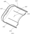
- a second stop rib 436 is provided on the inner side of the sliding lid 430 to correspond with the first stop rib 426.
- a fixed magnet 480 is provided on the fixed lid 420
- a sliding lid magnet 490 is provided on the sliding lid 430.
- the fixed magnet 480 is positioned on one side of the sliding lid magnet 490, and the poles of both the fixed magnet 480 and the sliding lid magnet 490 are arranged perpendicular to the sliding direction of the sliding lid 430.
- the adjacent poles of the sliding lid magnet 490 and the fixed magnet 480 are the same, creating a repelling magnetic force between them.
- the sliding lid magnet 490 when the sliding lid 430 is in the closed position, the sliding lid magnet 490 is closer to the side of the fixed magnet 480 that is near the closed position of the sliding lid 430. In this position, the magnetic force exerted by the fixed magnet 480 on the sliding lid magnet 490 is directed towards the closed position, preventing the sliding lid 430 from opening. Conversely, as shown in Figure 11 , when the sliding lid 430 is in the open position, the sliding lid magnet 490 is closer to the side of the fixed magnet 480 that is near the open position of the sliding lid 430. In this position, the magnetic force exerted by the sliding lid magnet 490 on the fixed magnet 480 is directed towards the open position, preventing the sliding lid 430 from closing.
- the user first needs to overcome the repelling force exerted by the fixed magnet 480 to move the sliding lid magnet 490 to a balanced position with the fixed magnet 480. Once the sliding lid 430 slides past this balanced position, the direction of the repelling force exerted by the fixed magnet 480 on the sliding lid magnet 490 changes towards the open position, allowing the sliding lid 430 to open automatically without the need for continued external force.
- the fixed magnet 480 comprises a first fixed magnet and a second fixed magnet, each located on either side of the sliding lid magnet 490.
- the first and second fixed magnets are arranged side by side, and the distance between the first fixed magnet and the sliding lid magnet 490 is equal to the distance between the second fixed magnet and the sliding lid magnet 490, approximately 6mm.
- the poles of the first fixed magnet, the sliding lid magnet 490, and the second fixed magnet can be arranged in the order of S, N, N, S, S, N. Both the first fixed magnet and the second fixed magnet apply magnetic forces of the same magnitude and direction to both sides of the sliding lid magnet 490, resulting in uniform force distribution on the sliding lid magnet 490, and thereby ensuring stable movement of the sliding lid 430.
- both the fixed magnet 480 and the sliding lid magnet 490 are bar-shaped magnets extending along the sliding direction of the sliding lid 430, and both magnets are of the same length.
- the first and second fixed magnets are arranged side by side on either side of the sliding lid magnet 490.
- the sliding lid magnet 490 moves between the first and second fixed magnets and is aligned with them, the sliding lid magnet 490 is in a state of equilibrium relative to the first and second fixed magnets.
- the magnetic forces exerted by the first and second fixed magnets on the sliding lid magnet 490 are perpendicular to the sliding direction of the sliding lid 430 and do not drive the movement of the sliding lid magnet 490.
- the length of the bar-shaped magnets can be chosen based on the desired travel distance of the sliding lid 430.
- the sliding lid magnet 490 when the sliding lid 430 is in the closed position, in the direction of its sliding, the sliding lid magnet 490 partially overlaps with the fixed magnet 480.
- the overlapping distance between the sliding lid magnet 490 and the fixed magnet 480 is 2-3mm. In this position, the repulsive force experienced by the sliding lid magnet 490 is significant and stable, enhancing the reliability of the sliding lid 430.
- the movement of the sliding lid 430 is triple the length of the bar-shaped magnets, making it easy to adjust the size of the magnets according to requirements.
- the bottom surface of the sliding lid magnet 490 is higher than the bottom surface of the fixed magnet 480.
- the sliding lid magnet 490 is subjected to the repelling force from the fixed magnet 480 directed towards the top surface of the sliding lid magnet 490.
- the sliding lid 430 does not adhere tightly to the fixed lid 420, reducing the friction during the sliding of the sliding lid 430 and making the opening and closing of the sliding lid 430 smoother.
- the distance between the bottom surface of the sliding lid magnet 490 and the bottom surface of the fixed magnet 480 is 1-2mm, maintaining the sliding lid 430 in an appropriate position, ensuring that the repelling force is neither too strong nor too weak.
- the fixed lid 420 is equipped with a fixed magnet accommodating groove 483 for housing the fixed magnet 480.
- the fixed magnet accommodating groove 483 can be set in the opening-side limit area 440.
- a sealing cover 484 is provided on the fixed magnet accommodating groove 483, and a sliding lid magnet accommodating box 491 for housing the sliding lid magnet 490 is set on the sliding lid 430. Both the sealing cover 484 and the sliding lid magnet accommodating box 491 are sealed using an ultrasonic welding process to prevent contamination of the water in the water cup 400.
Landscapes
- Engineering & Computer Science (AREA)
- Chemical & Material Sciences (AREA)
- Combustion & Propulsion (AREA)
- Physics & Mathematics (AREA)
- Mechanical Engineering (AREA)
- Thermal Sciences (AREA)
- General Engineering & Computer Science (AREA)
- Devices That Are Associated With Refrigeration Equipment (AREA)
Abstract
Description
- The present invention relates to the field of home appliances, particularly to a type of refrigerator.
- Currently, in household life, refrigerators have become an indispensable home appliance. To meet users' needs for accessing cold water, some refrigerators are equipped with a water tank and a water supply component that automatically supplies water to the tank. A dispenser connected to the water tank is installed on the door of the refrigerator, allowing users to obtain water from the tank via the dispenser. However, using the dispenser to dispense water is slow and cannot meet the demand for large quantities of water. Installing two water tanks inside the refrigerator would occupy too much space. Additionally, the room-temperature water in the pipelines may mix with the cold water in the tank inside the refrigerator, affecting the taste of the chilled water.
- To address the above problems, the present invention provides a refrigerator with a compact structure, featuring both a dispenser water tank and a water cup on its door.
- In order to achieve one of the above objects of the invention, an embodiment of the present invention provides a refrigerator comprising a cabinet and a door for opening and closing the cabinet, where the storage space defined by the cabinet comprises a refrigerating compartment and a freezing compartment; the door comprises a refrigerating door for opening and closing the refrigerating compartment and a freezing door for the freezing compartment; the door comprises a door shell and a door liner, with insulating material filled between the door shell and the door liner; a dispenser is provided on the door ; characterized in that, a water tank bracket is provided on the door liner of the refrigeration door, the water tank bracket comprises a dispenser water tank accommodating area and a water cup accommodating area set along the width direction of the refrigeration door, a dispenser water tank connected to the dispenser is provided in the dispenser water tank accommodating area, and a removable water cup is placed in the water cup accommodating area.
- As a further improvement of an embodiment of the present invention, wherein the dispenser is provided on the refrigerating door, and the water tank bracket is located behind the dispenser.
- As a further improvement of an embodiment of the present invention, wherein the refrigerating door comprises a hinge side connected to the cabinet and an opening side opposite the hinge side, the dispenser water tank accommodating area is close to the hinge side, the water cup accommodating area is close to the opening side, the water cup accommodating area has an opening end facing the opening side, and the direction of removing the water cup is parallel to the width direction of the door.
- As a further improvement of an embodiment of the present invention, wherein the dispenser water tank is cylindrical and vertically installed in the dispenser water tank accommodating area, the water cup is rectangular, and the length direction of the water cup is parallel to the width direction of the door.
- As a further improvement of an embodiment of the present invention, further comprising a water supply unit, an aperture for passing pipes corresponding to the dispenser water tank accommodating area is provided on the inner side of the refrigerating door, the water supply unit comprises a first water supply pipe connected to an external water source, the first water supply pipe enters the refrigerating door from the door shaft of the refrigerating door and exits through the aperture into the dispenser water tank accommodating area, the first water supply pipe is connected to the water inlet of the dispenser water tank, a second water supply pipe is also provided on the inner side of the refrigeration door, one end of the second water supply pipe is connected to the water outlet of the dispenser, and the other end passes through the aperture into the dispenser water tank accommodating area and is connected to the water outlet of the dispenser water tank.
- As a further improvement of an embodiment of the present invention, wherein the door liner towards the door shell side is connected to a water pipe bracket, the water pipe bracket has a pipe guiding cavity, an opening corresponding to the pipe guiding cavity is provided on the door liner, and an opening is provided on the wall of the pipe guiding cavity.
- As a further improvement of an embodiment of the present invention, wherein the water tank bracket further comprises a pipeline accommodating area provided above the water cup accommodating area, a valve with one inlet and two outlets is installed in the pipeline accommodating area, the water inlet of the valve is connected to the first water supply pipe, one water outlet of the valve is connected to the water inlet of the dispenser water tank through a third water supply pipe, and the other water outlet supplies water to the water cup.
- As a further improvement of an embodiment of the present invention, wherein a partition wall is provided between the pipeline accommodating area and the water cup accommodating area, the dual outlet valve is installed on the partition wall, the top of the water cup is provided with a water inlet, an opening corresponding to the water inlet of the water cup is provided on the partition wall, and the other water outlet of the dual outlet valve has a water nozzle provided in the opening.
- As a further improvement of an embodiment of the present invention, wherein there is a gap between the rear wall of the water cup accommodating area and the door liner, and a hall switch is installed, a magnet corresponding to the hall switch is provided on the inner wall of the water cup.
- As a further improvement of an embodiment of the present invention, wherein the bottom wall of the water cup accommodating area is provided with a water cup accommodating groove, the water cup accommodating groove is provided with an overflow groove and a drainage groove connecting the overflow groove with the rear wall of the water cup accommodating area, an overflow sensor is provided between the rear wall of the water cup accommodating area and the door liner, and the position of the overflow sensor corresponds to the position of the drainage groove.
- As a further improvement of an embodiment of the present invention, wherein the bottom wall of the water cup accommodating area is provided with a water cup accommodating groove, the bottom of the water cup is placed in the water cup accommodating groove, the water cup accommodating groove has a front wall and a rear wall parallel to the width direction of the refrigeration door, and two side walls connecting the front and rear walls, the side wall near the opening end is arc-shaped and lower than the front and rear walls of the water cup accommodating groove, the front and rear walls of the water cup accommodating groove near the opening end are sloped, forming a trumpet shape expanding towards the opening end.
- As a further improvement of an embodiment of the present invention, wherein the top wall of the water cup accommodating area is provided with an anti-tilt rib, and the anti-tilt rib is arc-shaped and positioned away from the opening end.
- The refrigerator provided by this invention comprises a refrigerator door provide with a water tank bracket, a dispenser water tank and a water cup provided in the bracket and arranged in the width direction of the door. The refrigerator provided by this invention provides a compact structure with a large storage capacity. Users can choose to obtain cold water from the dispenser water tank via the dispenser, or directly open the refrigeration door to take out the water cup for cold water, catering to diverse needs and enhancing user experience.
-
-
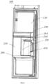
Figure 1 shows a schematic diagram of the refrigeration door in one embodiment of the present invention. -
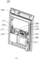
Figure 2 provides another schematic diagram of the refrigeration door shown inFigure 1 . -
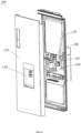
Figure 3 illustrates yet another schematic diagram of the refrigeration door shown inFigure 1 . -
Figure 4 depicts an exploded view of the refrigeration door shown inFigure 1 . -
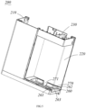
Figure 5 shows a three-dimensional schematic of the water tank bracket in one embodiment of this invention. -
Figure 6 is a three-dimensional schematic of the cup lid assembly in one embodiment of this invention. -
Figure 7 illustrates an exploded view of the cup lid assembly in one embodiment of this invention. -
Figure 8 presents a three-dimensional schematic of the sliding cover of the cup lid assembly shown inFigure 7 . -
Figure 9 shows an exploded view of the cup lid assembly in another embodiment of this invention. -
Figure 10 depicts the sliding cover of the cup lid assembly shown inFigure 9 in a closed position. -
Figure 11 displays the sliding cover of the cup lid assembly shown inFigure 9 in an open position. - In order to enable those in the art to better understand the technical solutions in the present invention, the technical solutions in the embodiments of the present invention will be clearly and completely described below in conjunction with the accompanying drawings in the embodiments of the present invention, and it is obvious that the described embodiments are only a part of the embodiments of the present invention and not all of the embodiments. Based on the embodiments in the present invention, all other embodiments obtained by a person of ordinary skill in the art without making creative labor shall fall within the scope of protection of the present invention.
- Refer to
Figures 1 to 5 , an embodiment of the invention provides a refrigerator, comprising a cabinet and a door used to open and close the cabinet. The door can be pivotally connected to the cabinet via a hinge. The storage space defined by the cabinet can comprise a refrigerating compartment and a freezing compartment. The door comprises a refrigeratingdoor 100 for opening and closing the refrigerating compartment and a freezing door for opening and closing the freezing compartment. The door comprises adoor shell 110 and adoor liner 120, with insulating material filled between thedoor shell 110 and thedoor liner 120 to prevent the leakage of cold air from the cabinet. The insulating material can be foam material. - A
dispenser 130 can also be provided on the door. The refrigerator can have a water tank and an ice-making device provided inside, allowing users to take out ice cubes and water stored in the refrigerator through thedispenser 130 without opening the door. - In this embodiment, the
door liner 120 of therefrigeration door 100 is provided with awater tank bracket 220. Thewater tank bracket 220 comprises a dispenser watertank accommodating area 210 and a water cupaccommodating area 220, both arranged along the width direction of the refrigeratingdoor 100. Adispenser water tank 300 connected to thedispenser 130 is provided in the dispenser watertank accommodating area 210, and aremovable water cup 400 is placed in the watercup accommodating area 220. - In use, users can take water from the
dispenser water tank 300 through thedispenser 130. Users can also directly remove thewater cup 400 from thewater tank bracket 220 to use cold water. Thus, with both thedispenser water tank 300 and thewater cup 400 provided on the refrigeratingdoor 100, it meets various water using needs of users. Directly providing thewater tank bracket 220 on therefrigeration door 100, and centralizing thedispenser water tank 300 andwater cup 400 within thewater tank bracket 220, where they are arranged along the door width direction, does not affect the installation of theshelf 190 on therefrigeration door 100. The overall structure is compact, and the space utilization rate is high. - Furthermore, in this embodiment of the invention, the
dispenser 130 is provided on the refrigeratingdoor 100, and thewater tank bracket 220 is provided behind thedispenser 130. Thedoor shell 110 of the refrigeratingdoor 100 can have a dispenser housing that recesses towards thedoor liner 120 side. Thedoor liner 120 corresponding to the position ofdispenser 130 protrudes towards the cabinet of the refrigerator to ensure enough foam material is filled between the dispenser housing and thedoor liner 120, ensuring insulation. - In this embodiment, the
water tank bracket 220 is provided behind thedispenser 130, making full use of the space on the door corresponding to the location of thedispenser 130. - Furthermore, the refrigerating
door 100 comprises ahinge side 140 connected to the cabinet and anopening side 150 opposite to thehinge side 140. The dispenser watertank accommodating area 210 is near thehinge side 140, and the water cupaccommodating area 220 is near theopening side 150. The watercup accommodating area 220 has anopening end 221 facing theopening side 150, and the remove direction of thewater cup 400 is parallel to the width direction of therefrigeration door 100. Specifically, thedispenser water tank 300 is cylindrical and vertically installed in the dispenser watertank accommodating area 210. Thewater cup 400 is rectangular, and its length direction is parallel to the width direction of the door. - The
water tank bracket 220 can be rectangular, with a partition between the dispenser watertank accommodating area 210 and the watercup accommodating area 220. The interior accommodating space of the watercup accommodating area 220 can be rectangular, and the wall of the watercup accommodating area 220 facing the cabinet can be transparent, allowing users to directly observe the water level inside thewater cup 400. Thewater cup 400 can have ahandle 411 facing the openingend 221, allowing users to remove thewater cup 400 parallel to the width direction of the door. The rectangular shape of thewater cup 400, with its length parallel to the door's width, minimizes the occupation of the interior space of the cabinet, making efficient use of the space on the door. Additionally, ashelf 190 can be installed on therefrigeration door 100, where theshelf 190 is located above thewater tank bracket 220, and thewater tank bracket 220 can be level with theshelf 190, creating an aesthetically pleasing overall appearance. - Furthermore, a water supply unit is also provided in the refrigerator, which can supply water to the ice maker, the
dispenser water tank 300, and thewater cup 400 automatically. Alternatively, it can supply water only to the ice maker and thedispenser water tank 300, while thewater cup 400 can be manually filled by the user after removal. Aaperture 160 is provided on the inner side of the refrigeratingdoor 100, corresponding to the dispenser watertank accommodating area 210,the water supply unit comprises a firstwater supply pipe 170 connecting to an external water source. The firstwater supply pipe 170 enters the refrigeratingdoor 100 through the door hinge and comes out through theaperture 160 into the dispenser watertank accommodating area 210. The firstwater supply pipe 170 is connected to thewater inlet 310 of thedispenser water tank 300 to supply water to thedispenser water tank 300. Specifically, the firstwater supply pipe 170 can be directly connected to thewater inlet 310 of thedispenser water tank 300, or can be connected through a valve. Additionally, a secondwater supply pipe 171 is provided on the inner side of the refrigeratingdoor 100, one end of which is connected to the water outlet of thedispenser 130, and the other end passes through theaperture 160 into the dispenser watertank accommodating area 210 and is connected to thewater outlet 320 of thedispenser water tank 300. - In this embodiment, an external water source can be connected to the first
water supply pipe 170 which supplies water to thedispenser water tank 300 and the water supply pipe which supplies water to the ice maker via valve having one inlet and two outlet. The firstwater supply pipe 170 enters the foam layer of the refrigeratingdoor 100 from the door axle, then passes through theaperture 160 into the dispenser watertank accommodating area 210, connecting to thedispenser water tank 300. The secondwater supply pipe 171 is also embedded in the foam layer of the refrigeratingdoor 100 and passes through theaperture 160 into the dispenser watertank accommodating area 210, connecting to thewater outlet 320 of thedispenser water tank 300. - An external water source supplies water to the
dispenser water tank 300 through the firstwater supply pipe 170, and then thedispenser water tank 300 supplies water to thedispenser 130 through the secondwater supply pipe 171. Both the first and the second water supply pipes directly enter the dispenser watertank accommodating area 210 through theaperture 160, shortening the water supply route. - Furthermore, a
water pipe bracket 180 is also provided between thedoor liner 120 and thedoor shell 110 of the refrigeratingdoor 100. Thewater pipe bracket 180 can be installed on thedoor liner 120, specifically, on the surface of thedoor liner 120 facing thedoor shell 110. During the manufacturing of the refrigerating door, thewater pipe bracket 180 can be pre-embedded in the foam layer between thedoor shell 110 and thedoor liner 120. Thewater pipe bracket 180 has a waterpipe guide cavity 181, the opening of the cavity of the waterpipe guide cavity 181 faces the side of thedoor liner 120, and the cavity wall of the waterpipe guide cavity 181 has theaperture 160. - Specifically, the
aperture 160 can consist of two parallel holes. Thewater pipe bracket 180 and theaperture 160 can position and fix the firstwater supply pipe 170 and the secondwater supply pipe 171, facilitating the installation of these pipes. During the installation and manufacturing process, thedispenser water tank 300 can be installed on thewater tank bracket 220, then thewater tank bracket 220 is installed on thedoor liner 120, and subsequently, the firstwater supply pipe 170, thedispenser water tank 300, and the secondwater supply pipe 171 are connected. The installation process is simple. - Furthermore, the
water tank bracket 220 also comprises a pipelineaccommodating area 230 located above the watercup accommodating area 220. Avalve 240 with one inlet and two outlets is installed in the pipelineaccommodating area 230, the firstwater supply pipe 170 connected to the inlet of thevalve 240. One outlet of thevalve 240 connects to thewater inlet 310 of thedispenser water tank 300 through a thirdwater supply pipe 172, while the other outlet supplies water to thewater cup 400. The external water source supplies water to both thedispenser water tank 300 and thewater cup 400 automatically through the firstwater supply pipe 170 via thevalve 240. - A
partition wall 250 is placed between the pipelineaccommodating area 230 and the watercup accommodating area 220, with thevalve 240 installed on thepartition wall 250. Thepartition wall 250 forms the top wall of the watercup accommodating area 220. The top of thewater cup 400 can have a water inlet, and water can be supplied into thewater cup 400 through this inlet. An opening corresponding to the water inlet of thewater cup 400 is provided on thepartition wall 250, and the outlet of thevalve 240 has a spout that is placed directly in the opening of thepartition wall 250 to supply water into thewater cup 400. - In this embodiment, a limiting rib plate for installing a
dual outlet valve 240 can be provided on thepartition wall 250. Thevalve 240 can be directly fixed to thepartition wall 250 with screws or other fasteners. During the manufacturing and installation process, thedispenser water tank 300 and thevalve 240 are first fixed to thewater tank bracket 220 with screws or other fasteners. Then, the thirdwater supply pipe 172, connecting the water outlet of thevalve 240 and thewater inlet 310 of thedispenser water tank 300, is installed. Finally, thewater tank bracket 220 is mounted to thedoor liner 120. Then, connecting the firstwater supply pipe 170 within the dispenser watertank accommodating area 210 to the inlet of thevalve 240, and connecting the secondwater supply pipe 171 to thewater outlet 320 of thedispenser water tank 300. This assembly is simple, with short piping. The water supply pipes, water valve,dispenser water tank 300, andwater cup 400 are all housed within the accommodating space of thewater tank bracket 220, resulting in a compact structure that occupies minimal space and is aesthetically pleasing. - Furthermore, a gap is left between the rear wall of the water
cup accommodating area 220 and thedoor liner 120, where a Hall switch is installed. A magnet is positioned on the inner wall of thewater cup 400 corresponding to the Hall switch. When thewater cup 400 is placed in the watercup accommodating area 220, the magnet corresponds to the Hall switch. The Hall switch can detect whether the magnet in thewater cup 400 is in the proper position within the watercup accommodating area 220, thus controlling whether to inject water into thewater cup 400. - A overflow sensor is also installed between the rear wall of the water
cup accommodating area 220 and thedoor liner 120 to detect the liquid level inside thewater cup 400. Both the Hall switch and the overflow sensor are mounted between the rear wall of the watercup accommodating area 220 and thedoor liner 120, reducing the occupation of vertical space and avoiding interference with the installation of theshelf 190. - Moreover, as shown in
Figure 5 , the bottom wall of the watercup accommodating area 220 is provided with a watercup accommodating groove 260. The shape of the watercup accommodating groove 260 matches the bottom shape of thewater cup 400. When thewater cup 400 is placed inside the watercup accommodating area 220, the bottom of thewater cup 400 rests in the watercup accommodating groove 260 to prevent thewater cup 400 from tipping over. Anoverflow groove 270 and adrainage groove 271 are provided within the watercup accommodating groove 260. Theoverflow groove 270 can be formed by a recess in the bottom part of the watercup accommodating groove 260, and thedrainage groove 271 can penetrate one side wall of theoverflow groove 270, connecting theoverflow groove 270 to the rear wall of the watercup accommodating area 220. If water spills from thewater cup 400 due to movement during the opening and closing of the door or if water overflows during the filling process, the spilled water will flow into theoverflow groove 270 at the bottom and then into thedrainage groove 271. - An overflow sensor is installed between the rear wall of the water
cup accommodating area 220 and thedoor liner 120, corresponding to the location of thedrainage groove 271. Specifically, the overflow sensor is mounted on therear wall 262 of the watercup accommodating area 220. The overflow sensor can detect whether there is water in thedrainage groove 271, thereby determining whether water has overflowed from thewater cup 400. If water overflow in thewater cup 400 is detected during the filling process, the water injection into thewater cup 400 is stopped. If water overflow in thewater cup 400 is detected after the filling is complete, a reminder can be issued to alert the user. - Furthermore, the water
cup accommodating groove 260 is approximately rectangular, havingfront wall 261 andrear wall 262 parallel to the width direction of therefrigeration door 100, and twoside walls 263 connecting thefront wall 261 and therear wall 262. Theside wall 263 near the openingend 221 is arc-shaped and lower than thefront wall 261 and therear wall 262 of the watercup accommodating groove 260. Thefront wall 261 and therear wall 262 of the watercup accommodating groove 260 are inclined towards the openingend 221, forming a funnel shape to guide the direction and position of thewater cup 400 when placed by the user. - The top wall of the water
cup accommodating area 220 is equipped with ananti-tilt rib 264, which is arc-shaped and located away from the openingend 221. When thewater cup 400 is placed in the watercup accommodating area 220, the top of thewater cup 400 rests against theAnti-tilt rib 264, preventing thewater cup 400 from tipping over due to movement of the door. The arc shape of theanti-tilt rib 264 avoids interference when inserting thewater cup 400. - Furthermore, the
water cup 400 comprises acup body 410 and a cup lid assembly. As shown inFigures 6 to 8 , in this embodiment of the invention, the cup lid assembly comprises a fixedlid 420 and a slidinglid 430 connected to the fixedlid 420. The fixedlid 420 can be fixedly installed at the opening of thecup body 410, with anopening 451 provided on the fixedlid 420, and the slidinglid 430 can be used to close theopening 451 of the fixedlid 420. - At the
opening 451 of the fixedlid 420, atea compartment connector 471 can be provided, on which atea compartment 470 can be mounted. Through theopening 451 on the fixedlid 420, tea leaves can be placed into thetea compartment 470 without opening the entire lid assembly. Thetea compartment connector 471 is made of a soft rubber material, while the fixedlid 420 is made of a hard rubber material. Thetea compartment connector 471 and the fixedlid 420 are integrally formed through molding process to prevent gaps between the fixedlid 420 and thetea compartment connector 471, thus avoiding the accumulation of dirt and grime. - On both side walls of the fixed
lid 420, soft rubber strips 427 are provided. When the fixedlid 420 is installed on thecup body 410, it seals the opening of thecup body 410 through the soft rubber strips 427. The two side walls of the fixedlid 420 also have a pair of parallelfirst slide grooves 421. - Additionally, there are
second slide grooves 422 on the fixedlid 420, parallel to thefirst slide grooves 421. The edges of the slidinglid 430 haveflanges 431, on which a pair of first slide rails 432 are provided to match with thefirst slide grooves 421. On the inner side of the slidinglid 430, second slide rails 433 are provided to match with thesecond slide grooves 422. The end surface of thefirst slide rail 432 is an arc surface that contacts thefirst slide groove 421 linearly. - In this embodiment, the side walls of the fixed
lid 420 have several ribs provided around the circumference of the fixedlid 420. Specifically, on the side walls of the fixedlid 420, there are upper ribs provided along the upper edge, lower ribs provided along the lower edge, and two ribs provided in the middle, all of which are parallel to each other. The two lower ribs form a slot for installing thesoft rubber strip 427, while the upper two ribs form thefirst slide groove 421. The surface of the fixedlid 420 has a pair ofsecond slide grooves 422, and the inner surface of the slidinglid 430 has a pair of rib plates forming thesecond slide rail 433 that matches with thesecond slide grooves 422. The slidinglid 430 has adownward flange 431 at the edge, on which thefirst slide rail 432 is provided to match with thefirst slide groove 421. Specifically, thefirst slide rail 432 can be a rib provided on theflange 431, and the surface of thefirst slide rail 432 towards the side wall of the fixedlid 420 is curved, contacting the side wall of the fixedlid 420 linearly, thus reducing friction during the sliding process of the slidinglid 430. Additionally, the double slide rail structure, with thesecond slide groove 422, provides auxiliary limiting guidance, preventing dislocation due to diminishing contact between the two sides of thefirst slide rail 432 and thefirst slide groove 421 during the opening process. - The upper ribs of the fixed
lid 420 are placed between the body of the slidinglid 430 and thefirst slide rail 432. The connecting surface between thefirst slide rail 432 and the body of the slidinglid 430 is slanted, contacting the fixedlid 420 linearly, thereby further reducing the friction during the sliding process of the slidinglid 430. - Furthermore, in this embodiment of the invention, the top surface of the fixed
lid 420 has resistance-reducingribs 423 parallel to the sliding direction of the slidinglid 430, with the slidinglid 430 supported on the resistance-reducingribs 423. Specifically, the resistance-reducingribs 423 are provided on the surface of the fixedlid 420 and are located between thefirst slide groove 421 and thesecond slide groove 422. During the sliding process of the slidinglid 430, the contact between the body of the slidinglid 430 and the fixedlid 420 is linear, as is the contact with the grooves, resulting in less resistance during sliding, thus enhancing the user experience. - Furthermore, a
closure limit rib 424 is provided within thefirst slide groove 422, and aclosure limit slot 434 is provided on thefirst slide rail 432. Both theclosure limit rib 424 and theclosure limit slot 434 are positioned near the end that is close to the closed position. When the slidinglid 430 is closed, theclosure limit rib 424 matches with theclosure limit slot 434. When a user slides to open the slidinglid 430, it drives the disengagement of theclosure limit rib 424 from theclosure limit slot 434. - The configuration of the
closure limit rib 424 and theclosure limit slot 434 prevents sealing issues due to sliding post-closure. Additionally, with theclosure limit rib 424 provided on the side of the closed position, it prevents one end of the slidinglid 430 from lifting up. Moreover, during the process of opening the slidinglid 430, the user needs to first apply an external force to disengage theclosure limit rib 424 from theclosure limit slot 434. After this, they can smoothly pull the slidinglid 430, resulting in a better user experience. - Furthermore, the lid assembly comprises an
anti-warping rib 435 provided on one of the fixedlid 420 and the slidinglid 430, and ananti-warping groove 425 provided on the other. Both theanti-warping rib 435 and theanti-warping groove 425 are positioned at the end far from the opening position of the slidinglid 430. When the slidinglid 430 is in the closed position, theanti-warping rib 435 fits into theanti-warping groove 425. - In this embodiment, the
anti-warping groove 425 is provided on the end surface of the fixedlid 420 perpendicular to the sliding direction, and theanti-warping rib 435 is provided on theflange 431 of the slidinglid 430, also perpendicular to the sliding direction. When the slidinglid 430 slides to the closed position, theanti-warping rib 435 on the slidinglid 430 inserts into theanti-warping groove 425 to prevent the end of the slidinglid 430 from warping. - Further, the fixed
lid 420 is provided with anopening area 450 and limit areas on both sides of the opening area, the limit areas comprise an opening-side limit area 440 and a closing-side limit area 460. Theopening 451 of the fixedlid 420 is located in theopening area 450, and both the opening-side limit area 440 and the closing-side limit area 460 are higher than theopening area 450. The opening-side limit area 440 is provided near the opening position, and the closing-side limit area 460 is provided near the closing position, with thesecond slide groove 422 possibly provided in the opening-side limit area 440. - The connection wall between the opening-
side limit area 440 and theopening area 450 forms an opening-side limit wall 441, and the connection wall between the closing-side limit area 460 and theopening area 450 forms a closing-side limit wall 462. When the slidinglid 430 is in the open position, theflange 431 at the closing end of the slidinglid 430 abuts the opening-side limit wall 441, restricting further sliding of the slidinglid 430 to prevent it from falling off. When the slidinglid 430 is in the closed position, theflange 431 at the closing end of the slidinglid 430 abuts the closing-side limit wall 462, preventing excessive sliding of the slidinglid 430. - Additionally, the
opening 451 on the fixedlid 420 is circular, with the opening-side limit wall 441 comprising a concave arc section concentric with theopening 451 and a horizontal section perpendicular to the sliding direction of the slidinglid 430. The closing-side limit wall 462 is shaped to match the opening-side limit wall 441, comprising a convex arc section that matches the concave arc section of the opening-side limit wall 441. The shape of theflange 431 at the closing end of the slidinglid 430 is similar to that of the opening-side limit wall 441. Specifically, the shape of the slidinglid 430 is almost the same as that of the opening-side limit area 440. Therefore, when the slidinglid 430 moves to the closed or open position, the end at the closing position of the slidinglid 430 can fit well with either the opening-side limit wall 441 or the closing-side limit wall 461, providing effective limitation. - Furthermore, a first stop rib 426 is provided on the fixed
lid 420, perpendicular to the sliding direction of the slidinglid 430. The first stop rib 426 is located on the fixedlid 420 near the open position, specifically on the opening-side limit area 440. On the inner side of the slidinglid 430, asecond stop rib 436 is provided to correspond with the first stop rib 426. When the slidinglid 430 slides to the open position, thesecond stop rib 436 slides to the side of the first stop rib 426 near the open position, thereby preventing the slidinglid 430 from sliding towards the closed position. - Additionally, as shown in
Figure 9 , in this embodiment of the invention, afixed magnet 480 is provided on the fixedlid 420, and a slidinglid magnet 490 is provided on the slidinglid 430. On the axis perpendicular to the sliding direction of the slidinglid 430, the fixedmagnet 480 is positioned on one side of the slidinglid magnet 490, and the poles of both the fixedmagnet 480 and the slidinglid magnet 490 are arranged perpendicular to the sliding direction of the slidinglid 430. The adjacent poles of the slidinglid magnet 490 and the fixedmagnet 480 are the same, creating a repelling magnetic force between them. - As illustrated in
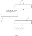
Figure 10 , when the slidinglid 430 is in the closed position, the slidinglid magnet 490 is closer to the side of the fixedmagnet 480 that is near the closed position of the slidinglid 430. In this position, the magnetic force exerted by the fixedmagnet 480 on the slidinglid magnet 490 is directed towards the closed position, preventing the slidinglid 430 from opening. Conversely, as shown inFigure 11 , when the slidinglid 430 is in the open position, the slidinglid magnet 490 is closer to the side of the fixedmagnet 480 that is near the open position of the slidinglid 430. In this position, the magnetic force exerted by the slidinglid magnet 490 on the fixedmagnet 480 is directed towards the open position, preventing the slidinglid 430 from closing. - During the process of sliding the sliding
lid 430 from the closed position to the open position, the user first needs to overcome the repelling force exerted by the fixedmagnet 480 to move the slidinglid magnet 490 to a balanced position with the fixedmagnet 480. Once the slidinglid 430 slides past this balanced position, the direction of the repelling force exerted by the fixedmagnet 480 on the slidinglid magnet 490 changes towards the open position, allowing the slidinglid 430 to open automatically without the need for continued external force. - Furthermore, in this embodiment of the invention, the fixed
magnet 480 comprises a first fixed magnet and a second fixed magnet, each located on either side of the slidinglid magnet 490. The first and second fixed magnets are arranged side by side, and the distance between the first fixed magnet and the slidinglid magnet 490 is equal to the distance between the second fixed magnet and the slidinglid magnet 490, approximately 6mm. - Perpendicular to the sliding direction of the sliding
lid 430, the poles of the first fixed magnet, the slidinglid magnet 490, and the second fixed magnet can be arranged in the order of S, N, N, S, S, N. Both the first fixed magnet and the second fixed magnet apply magnetic forces of the same magnitude and direction to both sides of the slidinglid magnet 490, resulting in uniform force distribution on the slidinglid magnet 490, and thereby ensuring stable movement of the slidinglid 430. - Furthermore, both the fixed
magnet 480 and the slidinglid magnet 490 are bar-shaped magnets extending along the sliding direction of the slidinglid 430, and both magnets are of the same length. - The first and second fixed magnets are arranged side by side on either side of the sliding
lid magnet 490. When the slidinglid magnet 490 moves between the first and second fixed magnets and is aligned with them, the slidinglid magnet 490 is in a state of equilibrium relative to the first and second fixed magnets. At this point, the magnetic forces exerted by the first and second fixed magnets on the slidinglid magnet 490 are perpendicular to the sliding direction of the slidinglid 430 and do not drive the movement of the slidinglid magnet 490. Additionally, in the design and manufacturing process, the length of the bar-shaped magnets can be chosen based on the desired travel distance of the slidinglid 430. - Furthermore, when the sliding
lid 430 is in the closed position, in the direction of its sliding, the slidinglid magnet 490 partially overlaps with the fixedmagnet 480. The overlapping distance between the slidinglid magnet 490 and the fixedmagnet 480 is 2-3mm. In this position, the repulsive force experienced by the slidinglid magnet 490 is significant and stable, enhancing the reliability of the slidinglid 430. - When the sliding
lid 430 is in the open position, in the direction of its sliding, there is a preset gap between the slidinglid magnet 490 and the fixedmagnet 480. This preset gap, when the slidinglid 430 is open, is the same as the overlap distance when the slidinglid 430 is closed, which is also 2-3mm. This setup ensures that the slidinglid magnet 490 is stably maintained in the open position. - Thus, the movement of the sliding
lid 430 is triple the length of the bar-shaped magnets, making it easy to adjust the size of the magnets according to requirements. - Furthermore, in the vertical direction, the bottom surface of the sliding
lid magnet 490 is higher than the bottom surface of the fixedmagnet 480. The slidinglid magnet 490 is subjected to the repelling force from the fixedmagnet 480 directed towards the top surface of the slidinglid magnet 490. As a result, under the influence of the magnetic force from the fixedmagnet 480, the slidinglid 430 does not adhere tightly to the fixedlid 420, reducing the friction during the sliding of the slidinglid 430 and making the opening and closing of the slidinglid 430 smoother. The distance between the bottom surface of the slidinglid magnet 490 and the bottom surface of the fixedmagnet 480 is 1-2mm, maintaining the slidinglid 430 in an appropriate position, ensuring that the repelling force is neither too strong nor too weak. - Specifically, the fixed
lid 420 is equipped with a fixedmagnet accommodating groove 483 for housing the fixedmagnet 480. The fixedmagnet accommodating groove 483 can be set in the opening-side limit area 440. A sealingcover 484 is provided on the fixedmagnet accommodating groove 483, and a sliding lidmagnet accommodating box 491 for housing the slidinglid magnet 490 is set on the slidinglid 430. Both the sealingcover 484 and the sliding lidmagnet accommodating box 491 are sealed using an ultrasonic welding process to prevent contamination of the water in thewater cup 400. - It should be understood that, although this specification is described in accordance with the embodiments, but not each embodiment contains only one independent technical program, the specification of this description is only for the sake of clarity, the person skilled in the art should take the specification as a whole, and the technical programs in the embodiments can be combined appropriately to form other embodiments that can be understood by the person skilled in the art.
- The above listed series of detailed description is only for the feasible embodiments of the present invention, is not used to limit the scope of protection of the present invention, where not out of the spirit of the art of the present invention equivalent embodiments or changes should be comprised in the scope of protection of the present invention.
Claims (12)
- A refrigerator comprising a cabinet and a door for opening and closing the cabinet, where the storage space defined by the cabinet comprises a refrigerating compartment and a freezing compartment; the door comprises a refrigerating door for opening and closing the refrigerating compartment and a freezing door for the freezing compartment; the door comprises a door shell and a door liner, with insulating material filled between the door shell and the door liner ; a dispenser is provided on the door ; characterized in that, a water tank bracket is provided on the door liner of the refrigeration door, the water tank bracket comprises a dispenser water tank accommodating area and a water cup accommodating area set along the width direction of the refrigeration door, a dispenser water tank connected to the dispenser is provided in the dispenser water tank accommodating area, and a removable water cup is placed in the water cup accommodating area.
- The refrigerator according to claim 1, wherein the dispenser is provided on the refrigerating door, and the water tank bracket is located behind the dispenser.
- The refrigerator according to claim 2, wherein the refrigerating door comprises a hinge side connected to the cabinet and an opening side opposite the hinge side, the dispenser water tank accommodating area is close to the hinge side, the water cup accommodating area is close to the opening side, the water cup accommodating area has an opening end facing the opening side, and the direction of removing the water cup is parallel to the width direction of the door.
- The refrigerator according to claim 3, wherein the dispenser water tank is cylindrical and vertically installed in the dispenser water tank accommodating area, the water cup is rectangular, and the length direction of the water cup is parallel to the width direction of the door.
- The refrigerator according to claim 2, further comprising a water supply unit, an aperture for passing pipes corresponding to the dispenser water tank accommodating area is provided on the inner side of the refrigerating door, the water supply unit comprises a first water supply pipe connected to an external water source, the first water supply pipe enters the refrigerating door from the door shaft of the refrigerating door and exits through the aperture into the dispenser water tank accommodating area, the first water supply pipe is connected to the water inlet of the dispenser water tank, a second water supply pipe is also provided on the inner side of the refrigeration door, one end of the second water supply pipe is connected to the water outlet of the dispenser, and the other end passes through the aperture into the dispenser water tank accommodating area and is connected to the water outlet of the dispenser water tank.
- The refrigerator according to claim 5, wherein the door liner towards the door shell side is connected to a water pipe bracket, the water pipe bracket has a pipe guiding cavity, an opening corresponding to the pipe guiding cavity is provided on the door liner, and an opening is provided on the wall of the pipe guiding cavity.
- The refrigerator according to claim 5, wherein the water tank bracket further comprises a pipeline accommodating area provided above the water cup accommodating area, a valve with one inlet and two outlets is installed in the pipeline accommodating area, the water inlet of the valve is connected to the first water supply pipe, one water outlet of the valve is connected to the water inlet of the dispenser water tank through a third water supply pipe, and the other water outlet supplies water to the water cup.
- The refrigerator according to claim 7, wherein a partition wall is provided between the pipeline accommodating area and the water cup accommodating area, the dual outlet valve is installed on the partition wall, the top of the water cup is provided with a water inlet, an opening corresponding to the water inlet of the water cup is provided on the partition wall, and the other water outlet of the dual outlet valve has a water nozzle provided in the opening.
- The refrigerator according to claim 7, wherein there is a gap between the rear wall of the water cup accommodating area and the door liner, and a hall switch is installed, a magnet corresponding to the hall switch is provided on the inner wall of the water cup.
- The refrigerator according to claim 7, wherein the bottom wall of the water cup accommodating area is provided with a water cup accommodating groove, the water cup accommodating groove is provided with an overflow groove and a drainage groove connecting the overflow groove with the rear wall of the water cup accommodating area, an overflow sensor is provided between the rear wall of the water cup accommodating area and the door liner, and the position of the overflow sensor corresponds to the position of the drainage groove.
- The refrigerator according to claim 4, wherein the bottom wall of the water cup accommodating area is provided with a water cup accommodating groove, the bottom of the water cup is placed in the water cup accommodating groove, the water cup accommodating groove has a front wall and a rear wall parallel to the width direction of the refrigeration door, and two side walls connecting the front and rear walls, the side wall near the opening end is arc-shaped and lower than the front and rear walls of the water cup accommodating groove, the front and rear walls of the water cup accommodating groove near the opening end are sloped, forming a trumpet shape expanding towards the opening end.
- The refrigerator according to claim 11, wherein the top wall of the water cup accommodating area is provided with an anti-tilt rib, and the anti-tilt rib is arc-shaped and positioned away from the opening end.
Applications Claiming Priority (2)
| Application Number | Priority Date | Filing Date | Title |
|---|---|---|---|
| CN202110710155.4A CN115523711A (en) | 2021-06-25 | 2021-06-25 | Refrigerator with a door |
| PCT/CN2022/100765 WO2022268164A1 (en) | 2021-06-25 | 2022-06-23 | Refrigerator |
Publications (2)
| Publication Number | Publication Date |
|---|---|
| EP4361540A1 true EP4361540A1 (en) | 2024-05-01 |
| EP4361540A4 EP4361540A4 (en) | 2025-01-08 |
Family
ID=84544157
Family Applications (1)
| Application Number | Title | Priority Date | Filing Date |
|---|---|---|---|
| EP22827656.4A Pending EP4361540A4 (en) | 2021-06-25 | 2022-06-23 | FRIDGE |
Country Status (4)
| Country | Link |
|---|---|
| EP (1) | EP4361540A4 (en) |
| CN (1) | CN115523711A (en) |
| AU (1) | AU2022298740B2 (en) |
| WO (1) | WO2022268164A1 (en) |
Families Citing this family (1)
| Publication number | Priority date | Publication date | Assignee | Title |
|---|---|---|---|---|
| WO2025001848A1 (en) * | 2023-06-26 | 2025-01-02 | 青岛海尔电冰箱有限公司 | Refrigerator, refrigerator control method, and storage medium |
Family Cites Families (8)
| Publication number | Priority date | Publication date | Assignee | Title |
|---|---|---|---|---|
| JPS5044371U (en) * | 1973-08-20 | 1975-05-06 | ||
| KR970028324A (en) * | 1995-11-24 | 1997-06-24 | 김광호 | Refrigerator dispenser |
| WO2011056031A2 (en) * | 2009-11-06 | 2011-05-12 | Lg Electronics Inc. | Refrigerator and water tank for refrigerator |
| CN203595335U (en) * | 2013-12-05 | 2014-05-14 | 海信容声(广东)冰箱有限公司 | Refrigerator water supply device |
| KR102674196B1 (en) * | 2017-01-03 | 2024-06-12 | 삼성전자주식회사 | Refrigerator and control method thereof |
| US10865092B1 (en) * | 2019-08-06 | 2020-12-15 | Haier Us Appliance Solutions, Inc. | Modular beverage-dispensing assembly for a refrigerator appliance |
| CN212205301U (en) * | 2020-03-16 | 2020-12-22 | 青岛海尔电冰箱有限公司 | Water supply device and refrigerator with same |
| CN215892936U (en) * | 2021-06-25 | 2022-02-22 | 青岛海尔电冰箱有限公司 | Refrigerator with a door |
-
2021
- 2021-06-25 CN CN202110710155.4A patent/CN115523711A/en active Pending
-
2022
- 2022-06-23 AU AU2022298740A patent/AU2022298740B2/en active Active
- 2022-06-23 WO PCT/CN2022/100765 patent/WO2022268164A1/en not_active Ceased
- 2022-06-23 EP EP22827656.4A patent/EP4361540A4/en active Pending
Also Published As
| Publication number | Publication date |
|---|---|
| CN115523711A (en) | 2022-12-27 |
| AU2022298740B2 (en) | 2025-02-20 |
| AU2022298740A1 (en) | 2023-12-14 |
| EP4361540A4 (en) | 2025-01-08 |
| WO2022268164A1 (en) | 2022-12-29 |
Similar Documents
| Publication | Publication Date | Title |
|---|---|---|
| US12326290B2 (en) | Refrigerator | |
| US12050044B2 (en) | Refrigerator | |
| US12196474B2 (en) | Refrigerator | |
| US11543173B2 (en) | Refrigerator | |
| CN103604260B (en) | A kind of water supplying apparatus for refrigerator and method of supplying water thereof | |
| CN203595335U (en) | Refrigerator water supply device | |
| EP4361540A1 (en) | Refrigerator | |
| CN215892936U (en) | Refrigerator with a door | |
| KR101639442B1 (en) | Refrigerator |
Legal Events
| Date | Code | Title | Description |
|---|---|---|---|
| STAA | Information on the status of an ep patent application or granted ep patent |
Free format text: STATUS: THE INTERNATIONAL PUBLICATION HAS BEEN MADE |
|
| PUAI | Public reference made under article 153(3) epc to a published international application that has entered the european phase |
Free format text: ORIGINAL CODE: 0009012 |
|
| STAA | Information on the status of an ep patent application or granted ep patent |
Free format text: STATUS: REQUEST FOR EXAMINATION WAS MADE |
|
| 17P | Request for examination filed |
Effective date: 20231130 |
|
| AK | Designated contracting states |
Kind code of ref document: A1 Designated state(s): AL AT BE BG CH CY CZ DE DK EE ES FI FR GB GR HR HU IE IS IT LI LT LU LV MC MK MT NL NO PL PT RO RS SE SI SK SM TR |
|
| DAV | Request for validation of the european patent (deleted) | ||
| DAX | Request for extension of the european patent (deleted) | ||
| RIC1 | Information provided on ipc code assigned before grant |
Ipc: F25D 11/00 20060101ALI20240911BHEP Ipc: F25D 23/02 20060101ALI20240911BHEP Ipc: F25D 23/04 20060101AFI20240911BHEP |
|
| A4 | Supplementary search report drawn up and despatched |
Effective date: 20241210 |
|
| RIC1 | Information provided on ipc code assigned before grant |
Ipc: F25D 11/00 20060101ALI20241204BHEP Ipc: F25D 23/02 20060101ALI20241204BHEP Ipc: F25D 23/04 20060101AFI20241204BHEP |