EP4361519A1 - A mounting bracket for fixing a heat pump system - Google Patents
A mounting bracket for fixing a heat pump system Download PDFInfo
- Publication number
- EP4361519A1 EP4361519A1 EP22204546.0A EP22204546A EP4361519A1 EP 4361519 A1 EP4361519 A1 EP 4361519A1 EP 22204546 A EP22204546 A EP 22204546A EP 4361519 A1 EP4361519 A1 EP 4361519A1
- Authority
- EP
- European Patent Office
- Prior art keywords
- mounting bracket
- indoor unit
- heat pump
- load
- bearing base
- Prior art date
- Legal status (The legal status is an assumption and is not a legal conclusion. Google has not performed a legal analysis and makes no representation as to the accuracy of the status listed.)
- Pending
Links
Images



Classifications
-
- F—MECHANICAL ENGINEERING; LIGHTING; HEATING; WEAPONS; BLASTING
- F24—HEATING; RANGES; VENTILATING
- F24F—AIR-CONDITIONING; AIR-HUMIDIFICATION; VENTILATION; USE OF AIR CURRENTS FOR SCREENING
- F24F13/00—Details common to, or for air-conditioning, air-humidification, ventilation or use of air currents for screening
- F24F13/20—Casings or covers
-
- F—MECHANICAL ENGINEERING; LIGHTING; HEATING; WEAPONS; BLASTING
- F24—HEATING; RANGES; VENTILATING
- F24F—AIR-CONDITIONING; AIR-HUMIDIFICATION; VENTILATION; USE OF AIR CURRENTS FOR SCREENING
- F24F1/00—Room units for air-conditioning, e.g. separate or self-contained units or units receiving primary air from a central station
- F24F1/0007—Indoor units, e.g. fan coil units
- F24F1/0043—Indoor units, e.g. fan coil units characterised by mounting arrangements
-
- F—MECHANICAL ENGINEERING; LIGHTING; HEATING; WEAPONS; BLASTING
- F24—HEATING; RANGES; VENTILATING
- F24F—AIR-CONDITIONING; AIR-HUMIDIFICATION; VENTILATION; USE OF AIR CURRENTS FOR SCREENING
- F24F13/00—Details common to, or for air-conditioning, air-humidification, ventilation or use of air currents for screening
- F24F13/32—Supports for air-conditioning, air-humidification or ventilation units
Definitions
- the invention relates to a mounting bracket for holding a heat pump system, wherein the mounting bracket comprises a load-bearing base frame capable of supporting at least the weight of an indoor unit, including a fluid, of a heat pump, wherein the load-bearing base frame forms a housing.
- a mounting bracket allows for mounting of an indoor unit of a heat pump system to the mounting bracket, where said mounting bracket can be placed on a floor or on top of a hot water tank.
- the invention further relates to a heat pump system comprising such a mounting bracket.
- Heating of water in buildings may be accomplished by means of a heat pump system.
- a heat pump system may either be a ground source heat pump (GSHP) system or an air source heat pump (ASHP) system.
- GSHP ground source heat pump
- ASHP air source heat pump
- GSHP ground source heat pump
- calories are exchanged between the ground, or ground water, and a fluid, the fluid in particular being air or water.
- the calories in the ground may be extracted by capturing calories in a water table or by circulating a water-based circuit in the ground.
- calories are exchanged between the air and a fluid, in particular air or water.
- a heat pump system may comprise an indoor unit that allows the management of the hot water supply within a building.
- the indoor unit typically comprises a heat pump circuit with a refrigerant in case of a split heat pump system or without a refrigerant in case of a monobloc heat pump system.
- the indoor unit usually comprises at least one fluid supply, such as a refrigerant or hot water, and several hot water outlets.
- the indoor unit may comprise several components, such as, a heater, a heat exchanger, an expansion tank, a pump, a three-way valve, a venting device, and an electronic control unit.
- floor standing systems typically include a hot water tank.
- the various components of the indoor unit are usually positioned around or above the hot water tank.
- These floor standing systems have a tower-like geometry, with a height that usually is much greater than the width and length of its base.
- Wall mounted systems are fixed to a wall. They may or may not be connected to a hot water tank, depending on the system configuration.
- Floor standing systems allow for a complete system to be integrated into one product, and they do not require wall mounting.
- floor standing systems have several constraints. In the event of a product failure, or product obsolescence due to aging, the whole product has to be changed. As a complete system, it is common that some of the functions available in the system are not used in the place of installation and thus over performs. This leads to a waste of components used and thus a waste of precious materials.
- floor standing systems are typically quite high and may not be compatible with the place of the installation, such as a low cellar or basement, or for example does not fit through a door properly when transporting the system to its installation site.
- Wall mounted systems alleviate most of these issues and is more flexible to be used with, for instance, different sizes of hot water tanks and can thus be build up in a modular fashion.
- Wall mounted systems can have a weight ranging from 30 kg to 130 kg, depending on the system specifications. This includes any fluid, such as water in an expansion tank or a buffer tank, present within the system. As such, it is necessary to have a load-bearing wall to allow the unit to be securely fixed to said wall. Thus, the place of installation is limited in buildings with a limited amount of load-bearing walls. Also, the dimensions of drill holes to fix the system to the wall need to be sufficiently large but that might lead to a deterioration of the wall's structural integrity.
- the wall has to be sufficiently straight with enough space available to accommodate the required dimensions of the system and to accommodate for the accessibility of the system components during maintenance. This may require to have a minimum distance between the system and, for instance, the corner of a room. Also, the drilling has to be done by a skilled and experienced installer to prevent the system from falling off the wall and potentially cause fatal damage to a user.
- a wall mounted system requires the connection of various elements.
- the system may be connected to an outdoor unit with hydraulic or refrigerant piping, depending on the system being a split or monobloc system.
- the system may also be connected to a hot water tank. This requires sufficient space, under and/or around the system, to make connections to said outdoor unit or hot water tank. Some connections, such as thermal and electrical connections, can present a safety risk for users when exposed.
- the connection points on the indoor unit of the wall mounted system are usually constructed in such a way that they are attached to the rear and/or the bottom of the system. This prevents the wall mounted system to be placed directly on the floor in case the building does not accommodate a suitable space for such a wall mounted system.
- a wall mounted system requires the system to be placed to the wall prior to any piping around it, limiting access for an installer.
- the object of the invention is obtained by means of a mounting bracket for fixing a heat pump system, wherein the mounting bracket comprises a load-baring base frame capable of supporting at least the weight of an indoor unit, including a fluid, of a heat pump, wherein the load-bearing base frame forms a housing with a height of at least 100 mm.
- the load-bearing base frame may be constructed as a single element or of multiple parts attached to each other, either directly or indirectly using other components.
- the load-bearing base frame may have at least three sides.
- the load-bearing base frame may form a rectangular shape.
- the load-bearing base frame may be capable of supporting at least the weight of an indoor unit, including a fluid, of a heat pump system.
- the load-bearing base frame When equipped with additional components, the load-bearing base frame may be capable of supporting the weight of the indoor unit, including a fluid, plus the weight of the additional components.
- the fluid residing in the indoor unit may be, for instance, water in an expansion tank, water in a buffer tank or water in multiple components.
- the load-bearing base frame may, as such, support a weight of an indoor unit in a range of at least 30 to 130 kg.
- the load-bearing base frame may be made from metal or plastic suitable to support said range of weight.
- the load-bearing base frame forms a housing with a height of at least 100 mm.
- the height of at least 100 mm ensures a minimal room for any connections situated at the bottom of an indoor unit of a heat pump system installed on the mounting bracket.
- the housing formed may as such be covered by the load-bearing base from on at least two lateral sides, preferably at least three lateral sides.
- the mounting bracket may have at least two openings. One opening may be on the top for allowing connections of an indoor unit to fit into the bracket. Another opening may be among one of the lateral sides to provide access from one of the lateral sides into the bracket. Optionally, a third opening may be provided on the bottom.
- Such a mounting bracket allows for mounting of an indoor unit of a heat pump system to the mounting bracket, where said mounting bracket can be placed on a floor or on top of a hot water tank, thereby having a safe and stable placement of an indoor unit without the need of installing the indoor unit to a wall. Also, the installation of the pipes can be done to the mounting bracket. Furthermore, such a mounting bracket allows for installing various components such as an expansion vessel into the mounting bracket and thus have a more flexible design of the indoor unit, more particular of the design of the installation as a whole, and thus achieving the object of the invention.
- the load-bearing base frame comprises at least three points forming a single plane, on the lowest surface of the mounting bracket, wherein the single plane is situated perpendicular to at least one face of an indoor unit when fixed to the mounting bracket.
- the at least three points may be at least three relatively small protrusions, such as feet or pins, for contact between the mounting bracket and the surface the mounting bracket rests on.
- the at least three points may also be at least three essentially flat surfaces, such as a metal or plastic strip, or a combination of small protrusions and flat surfaces.
- the at least three points form a single support plane supporting the mounting bracket and the indoor unit attached to the mounting bracket.
- the load-bearing base frame comprises reversible fastening means or holes for accepting reversible fastening means.
- Said reversible fastening means may be protrusions such as hooks, clips or threaded screw rods included into the load-bearing frame.
- Said holes allow for a reversible attachment of for instance, an indoor unit of a heat pump system, a hot water tank, or both to the mounting bracket.
- Said indoor unit, hot water tank or both may be mounted to the mounting bracket using reversible fastening means such as screws, bolts, nuts or clips.
- the fastening means are reversible, the indoor unit, the hot water tank, or both may be easily detached and reattached during maintenance or replacement of the indoor unit and/or the hot water tank.
- the housing has a height of at least 200 mm.
- a height of at least 200 mm sufficient room between the bottom of the mounting bracket and the bottom of an indoor unit, when installed, is realized to allow any connections of an indoor unit to be situated on the bottom side of the indoor unit while also having room for an operator to work on any of said connections.
- the load-bearing base frame is made of metal. By making the load-bearing base frame from metal, the base frame can be made sufficiently stiff and sturdy to support a weight range of an indoor unit of 30 to 130 kg.
- the mounting bracket further comprises a vertical frame extending essentially perpendicular to the load-bearing base frame.
- a vertical frame essentially perpendicular to the load-bearing base frame an L-shape design is created that allows a wall-mounted indoor unit to be fixed with its back side to the mounting bracket as if it was fixed to an actual wall.
- the vertical frame can as such act as a wall for a wall-mounted indoor unit, and the wall-mounted indoor unit can thus be placed securely and in a stable fashion onto the mounting bracket. This is especially helpful for when such an indoor unit does not have sufficient strength to rest with its bottom side onto the load-bearing base frame.
- the vertical frame should have a height of preferably at least 50% of the height of the wall-mounted indoor unit that would be fixed to it.
- the vertical frame should be at least high enough to reach any fixing points on the upper half of a wall-mounted indoor unit to prevent the indoor unit from falling off the vertical frame.
- the vertical frame comprises at least two fixing points for fixing an indoor unit of a heat pump system to the vertical frame.
- the fixing points may be holes drilled to the vertical frame.
- the fixing point may also be reversible fastening means.
- Said fixing points may be positioned to accommodate for any drilling points that would have to be made if the indoor unit would have been fixed to a wall.
- the vertical frame may comprise more than two fixing points for accommodating a range of different indoor units, of different sized, with different drilling point positions.
- the fixing points may come in sets of two fixing points, wherein the vertical frame may have multiple sets of fixing points. This allows different indoor units to be compatible with the same mounting bracket thus allowing for a larger or smaller assembly depending on the conditions and installation possibilities.
- the fixing points are positioned in such a manner that, when an indoor unit of a heat pump is fixed to said fixing points, a height difference between the bottom of the mounting bracket and the bottom of said indoor unit is realized of at least 100 mm. This ensures a minimal room for any connections between the bottom of the mounting bracket and the bottom of an indoor unit of a heat pump system installed on the mounting bracket.
- the vertical frame is positioned in such a way that, when an indoor unit is fixed to the vertical frame, the center of gravity of the indoor unit sits anywhere above the housing formed by the load-bearing base frame of the mounting bracket.
- the center of gravity of the indoor unit must sit anywhere above the housing formed by the load-bearing base frame.
- the load-bearing base frame forms, at its lowest surface, a support shape having an xy-plane which is essentially horizontal.
- the center of gravity of the indoor unit must sit anywhere above said support shape in order to prevent tilting of the entire assembly.
- the load-bearing base frame comprises at least three points forming a single support plane, the center of gravity should be sitting above said single support plane.
- the support shape or the single support plane of the load-bearing base frame should, when looking from the top or the bottom, cover at least 30% of the cross-section of the indoor unit, preferably 60%, more preferably 90%.
- a heat pump system for heating water in a building, wherein the heat pump system comprises a mounting bracket as described previously, and an indoor unit of a heat pump system attached onto the upper side of the load-bearing base frame or to the vertical frame of said mounting bracket.
- the heat pump system can be placed in a stable and safe manner on a floor.
- the heat pump system further comprises a hot water tank attached to the lower side of the load-bearing base frame of said mounting bracket.
- a hot water tank attached on the lower side of the mounting bracket a tower of a hot water tank and heat pump system can be created by using the mounting bracket as a coupling and interfacing element; allowing any connections between the hot water tank and the heat pump system to be situated within the inner space of the mounting bracket.
- the indoor unit or the hot water tank comprises a guiding structure for guiding the installation of the mounting bracket.
- the indoor unit or the hot water tank may have forms and counter-forms to guide the installation of the mounting bracket.
- the indoor unit or the hot water tank may for instance have protrusions or openings accommodating openings or protrusions on the mounting bracket. Both the indoor unit and the hot water tank may have said guiding structures.
- a mounting bracket 1 comprising a load-bearing base frame 2a, 2b, 2c and a guiding frame 3a, 3b attached to the load-bearing base frame elements 2a and 2b, respectively.
- a mounting bracket 1 is provided allowing a heat pump system indoor unit (not shown in this figure) to be placed upon the mounting bracket 1, in particular onto the upper side of the load-bearing base frame 2a, 2b, 2c.
- the guiding frame 3a, 3b are attached to the left and right side of the mounting bracket 1 to .
- the guiding frame 3a, 3b may guide the fixing of an indoor unit 11 to the mounting bracket 1.
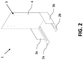
- FIG. 2 another mounting bracket 1 is shown comprising a load-bearing base frame 2a, 2b, and guiding frame 3a, 3b attached to the load-bearing base frame 2a, 2b.
- the guiding frame 3a, 3b acts not only as a guide for fixing an indoor unit 11 to the mounting bracket 1, but also to reinforce the structure of the mounting bracket 1.
- a vertical frame 4 is shown positioned perpendicular to the load-bearing base frame 2a, 2b and comprising multiple fixing points 5 or multiple sets of fixing points 5.
- the fixing points 5 are multiple drilled holes to accommodate for different heat pump system indoor units (not shown in this figure) or to accommodate for different installation heights to improve, for instance, ergonomics of the installation or the aesthetics of the assembly.
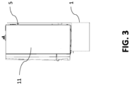
- FIGs 3 and 4 both show the mounting bracket 1 as presented in Figure 2 in combination with a wall mounted heat pump system indoor unit 11 fixed to fixing points 5.
- the indoor unit 11 is fixed to the vertical frame 4 and thus the indoor unit 11 is fixed in its vertical position as if it were mounted to a load bearing wall of a building.
- it may be both fixed to the vertical frame 4 and sit, horizontally, onto the upper side of the load-bearing base frame 2a, 2b, 2c.
- the mounting bracket 1 as presented in Figure 2 is shown in combination with both a wall mounted heat pump system indoor unit 11 and a hot water tank 21.
- the load-bearing base frame 2a, 2b sits horizontally on the hot water tank 21 while at the same time holding the indoor unit 11 on top of the mounting bracket 1 and creating a space between the hot water tank 21 and the indoor unit 11.
Landscapes
- Engineering & Computer Science (AREA)
- Chemical & Material Sciences (AREA)
- Combustion & Propulsion (AREA)
- Mechanical Engineering (AREA)
- General Engineering & Computer Science (AREA)
- Structures Of Non-Positive Displacement Pumps (AREA)
Abstract
Description
- The invention relates to a mounting bracket for holding a heat pump system, wherein the mounting bracket comprises a load-bearing base frame capable of supporting at least the weight of an indoor unit, including a fluid, of a heat pump, wherein the load-bearing base frame forms a housing. Such a mounting bracket allows for mounting of an indoor unit of a heat pump system to the mounting bracket, where said mounting bracket can be placed on a floor or on top of a hot water tank. The invention further relates to a heat pump system comprising such a mounting bracket.
- Heating of water in buildings, such as heating water of a central heating system or heating of water for domestic use, may be accomplished by means of a heat pump system. Such a heat pump system may either be a ground source heat pump (GSHP) system or an air source heat pump (ASHP) system. In a GSHP system, calories are exchanged between the ground, or ground water, and a fluid, the fluid in particular being air or water. The calories in the ground may be extracted by capturing calories in a water table or by circulating a water-based circuit in the ground. In an ASHP system calories are exchanged between the air and a fluid, in particular air or water.
- A heat pump system may comprise an indoor unit that allows the management of the hot water supply within a building. The indoor unit typically comprises a heat pump circuit with a refrigerant in case of a split heat pump system or without a refrigerant in case of a monobloc heat pump system. The indoor unit usually comprises at least one fluid supply, such as a refrigerant or hot water, and several hot water outlets. The indoor unit may comprise several components, such as, a heater, a heat exchanger, an expansion tank, a pump, a three-way valve, a venting device, and an electronic control unit.
- In general, there are two main classes of architecture for heat pump systems indoor units: floor standing systems and wall mounted systems. Floor standing systems typically include a hot water tank. The various components of the indoor unit are usually positioned around or above the hot water tank. These floor standing systems have a tower-like geometry, with a height that usually is much greater than the width and length of its base. Wall mounted systems are fixed to a wall. They may or may not be connected to a hot water tank, depending on the system configuration.
- Floor standing systems allow for a complete system to be integrated into one product, and they do not require wall mounting. However, floor standing systems have several constraints. In the event of a product failure, or product obsolescence due to aging, the whole product has to be changed. As a complete system, it is common that some of the functions available in the system are not used in the place of installation and thus over performs. This leads to a waste of components used and thus a waste of precious materials. Furthermore, floor standing systems are typically quite high and may not be compatible with the place of the installation, such as a low cellar or basement, or for example does not fit through a door properly when transporting the system to its installation site.
- Wall mounted systems alleviate most of these issues and is more flexible to be used with, for instance, different sizes of hot water tanks and can thus be build up in a modular fashion. Wall mounted systems, however, can have a weight ranging from 30 kg to 130 kg, depending on the system specifications. This includes any fluid, such as water in an expansion tank or a buffer tank, present within the system. As such, it is necessary to have a load-bearing wall to allow the unit to be securely fixed to said wall. Thus, the place of installation is limited in buildings with a limited amount of load-bearing walls. Also, the dimensions of drill holes to fix the system to the wall need to be sufficiently large but that might lead to a deterioration of the wall's structural integrity. The wall has to be sufficiently straight with enough space available to accommodate the required dimensions of the system and to accommodate for the accessibility of the system components during maintenance. This may require to have a minimum distance between the system and, for instance, the corner of a room. Also, the drilling has to be done by a skilled and experienced installer to prevent the system from falling off the wall and potentially cause fatal damage to a user.
- Furthermore, a wall mounted system requires the connection of various elements. For instance, the system may be connected to an outdoor unit with hydraulic or refrigerant piping, depending on the system being a split or monobloc system. The system may also be connected to a hot water tank. This requires sufficient space, under and/or around the system, to make connections to said outdoor unit or hot water tank. Some connections, such as thermal and electrical connections, can present a safety risk for users when exposed. But above all, the connection points on the indoor unit of the wall mounted system are usually constructed in such a way that they are attached to the rear and/or the bottom of the system. This prevents the wall mounted system to be placed directly on the floor in case the building does not accommodate a suitable space for such a wall mounted system. Also, a wall mounted system requires the system to be placed to the wall prior to any piping around it, limiting access for an installer.
- It is therefore desired to facilitate a flexibility of installation of wall mounted systems, allowing widespread use of such a system, by means of a mounting bracket or interface for accepting and holding such a wall mounted system without the need to install the wall mounted system directly to the wall of a building.
- The object of the invention is obtained by means of a mounting bracket for fixing a heat pump system, wherein the mounting bracket comprises a load-baring base frame capable of supporting at least the weight of an indoor unit, including a fluid, of a heat pump, wherein the load-bearing base frame forms a housing with a height of at least 100 mm. The load-bearing base frame may be constructed as a single element or of multiple parts attached to each other, either directly or indirectly using other components. The load-bearing base frame may have at least three sides. The load-bearing base frame may form a rectangular shape. The load-bearing base frame may be capable of supporting at least the weight of an indoor unit, including a fluid, of a heat pump system. When equipped with additional components, the load-bearing base frame may be capable of supporting the weight of the indoor unit, including a fluid, plus the weight of the additional components. The fluid residing in the indoor unit may be, for instance, water in an expansion tank, water in a buffer tank or water in multiple components. The load-bearing base frame may, as such, support a weight of an indoor unit in a range of at least 30 to 130 kg. The load-bearing base frame may be made from metal or plastic suitable to support said range of weight. The load-bearing base frame forms a housing with a height of at least 100 mm. As such, when the mounting bracket is placed on either the floor or a hot water tank, the height of at least 100 mm ensures a minimal room for any connections situated at the bottom of an indoor unit of a heat pump system installed on the mounting bracket. The housing formed may as such be covered by the load-bearing base from on at least two lateral sides, preferably at least three lateral sides. The mounting bracket may have at least two openings. One opening may be on the top for allowing connections of an indoor unit to fit into the bracket. Another opening may be among one of the lateral sides to provide access from one of the lateral sides into the bracket. Optionally, a third opening may be provided on the bottom. Such a mounting bracket allows for mounting of an indoor unit of a heat pump system to the mounting bracket, where said mounting bracket can be placed on a floor or on top of a hot water tank, thereby having a safe and stable placement of an indoor unit without the need of installing the indoor unit to a wall. Also, the installation of the pipes can be done to the mounting bracket. Furthermore, such a mounting bracket allows for installing various components such as an expansion vessel into the mounting bracket and thus have a more flexible design of the indoor unit, more particular of the design of the installation as a whole, and thus achieving the object of the invention.
- In an embodiment, the load-bearing base frame comprises at least three points forming a single plane, on the lowest surface of the mounting bracket, wherein the single plane is situated perpendicular to at least one face of an indoor unit when fixed to the mounting bracket. The at least three points may be at least three relatively small protrusions, such as feet or pins, for contact between the mounting bracket and the surface the mounting bracket rests on. The at least three points may also be at least three essentially flat surfaces, such as a metal or plastic strip, or a combination of small protrusions and flat surfaces. The at least three points form a single support plane supporting the mounting bracket and the indoor unit attached to the mounting bracket.
- In an embodiment, the load-bearing base frame comprises reversible fastening means or holes for accepting reversible fastening means. Said reversible fastening means may be protrusions such as hooks, clips or threaded screw rods included into the load-bearing frame. Said holes allow for a reversible attachment of for instance, an indoor unit of a heat pump system, a hot water tank, or both to the mounting bracket. Said indoor unit, hot water tank or both may be mounted to the mounting bracket using reversible fastening means such as screws, bolts, nuts or clips. As the fastening means are reversible, the indoor unit, the hot water tank, or both may be easily detached and reattached during maintenance or replacement of the indoor unit and/or the hot water tank.
- In an embodiment, the housing has a height of at least 200 mm. By having a height of at least 200 mm, sufficient room between the bottom of the mounting bracket and the bottom of an indoor unit, when installed, is realized to allow any connections of an indoor unit to be situated on the bottom side of the indoor unit while also having room for an operator to work on any of said connections.
- In an embodiment, the load-bearing base frame is made of metal. By making the load-bearing base frame from metal, the base frame can be made sufficiently stiff and sturdy to support a weight range of an indoor unit of 30 to 130 kg.
- In an embodiment, the mounting bracket further comprises a vertical frame extending essentially perpendicular to the load-bearing base frame. By having a vertical frame essentially perpendicular to the load-bearing base frame, an L-shape design is created that allows a wall-mounted indoor unit to be fixed with its back side to the mounting bracket as if it was fixed to an actual wall. Thus, the vertical frame can as such act as a wall for a wall-mounted indoor unit, and the wall-mounted indoor unit can thus be placed securely and in a stable fashion onto the mounting bracket. This is especially helpful for when such an indoor unit does not have sufficient strength to rest with its bottom side onto the load-bearing base frame. Thus, a nominal installation and reliability is secured by fixing the indoor unit with its backside to the vertical frame without the need to attach it to an actual wall of a building. The vertical frame should have a height of preferably at least 50% of the height of the wall-mounted indoor unit that would be fixed to it. The vertical frame should be at least high enough to reach any fixing points on the upper half of a wall-mounted indoor unit to prevent the indoor unit from falling off the vertical frame. In an embodiment, the vertical frame comprises at least two fixing points for fixing an indoor unit of a heat pump system to the vertical frame. The fixing points may be holes drilled to the vertical frame. The fixing point may also be reversible fastening means. Said fixing points may be positioned to accommodate for any drilling points that would have to be made if the indoor unit would have been fixed to a wall. As such, the vertical frame may comprise more than two fixing points for accommodating a range of different indoor units, of different sized, with different drilling point positions. The fixing points may come in sets of two fixing points, wherein the vertical frame may have multiple sets of fixing points. This allows different indoor units to be compatible with the same mounting bracket thus allowing for a larger or smaller assembly depending on the conditions and installation possibilities.
- In an embodiment, the fixing points are positioned in such a manner that, when an indoor unit of a heat pump is fixed to said fixing points, a height difference between the bottom of the mounting bracket and the bottom of said indoor unit is realized of at least 100 mm. This ensures a minimal room for any connections between the bottom of the mounting bracket and the bottom of an indoor unit of a heat pump system installed on the mounting bracket.
- In an embodiment, the vertical frame is positioned in such a way that, when an indoor unit is fixed to the vertical frame, the center of gravity of the indoor unit sits anywhere above the housing formed by the load-bearing base frame of the mounting bracket.
- When an indoor unit is attached to the vertical frame, the assembled construction should not tilt over. As such, the center of gravity of the indoor unit must sit anywhere above the housing formed by the load-bearing base frame. In particular, the load-bearing base frame forms, at its lowest surface, a support shape having an xy-plane which is essentially horizontal. The center of gravity of the indoor unit must sit anywhere above said support shape in order to prevent tilting of the entire assembly. When the load-bearing base frame comprises at least three points forming a single support plane, the center of gravity should be sitting above said single support plane. The support shape or the single support plane of the load-bearing base frame should, when looking from the top or the bottom, cover at least 30% of the cross-section of the indoor unit, preferably 60%, more preferably 90%.
- In an aspect of the invention, a heat pump system for heating water in a building, wherein the heat pump system comprises a mounting bracket as described previously, and an indoor unit of a heat pump system attached onto the upper side of the load-bearing base frame or to the vertical frame of said mounting bracket. By having a heat pump system attached on the upper side of the load-bearing base frame (2a, 2b, 2c) or to the vertical frame (4) of the mounting bracket, the heat pump system can be placed in a stable and safe manner on a floor.
- In an embodiment, the heat pump system further comprises a hot water tank attached to the lower side of the load-bearing base frame of said mounting bracket. By having a hot water tank attached on the lower side of the mounting bracket, a tower of a hot water tank and heat pump system can be created by using the mounting bracket as a coupling and interfacing element; allowing any connections between the hot water tank and the heat pump system to be situated within the inner space of the mounting bracket.
- In an embodiment, the indoor unit or the hot water tank comprises a guiding structure for guiding the installation of the mounting bracket. To ensure the indoor unit or the hot water tank are correctly mounted to the mounting bracket, they may have forms and counter-forms to guide the installation of the mounting bracket. The indoor unit or the hot water tank may for instance have protrusions or openings accommodating openings or protrusions on the mounting bracket. Both the indoor unit and the hot water tank may have said guiding structures.
- In the figures, the subject-matter of the invention is schematically shown, wherein identical or similarly acting elements are usually provided with the same reference signs.
- Figure 1
- shows a schematic representation of a mounting bracket according to the present invention.
- Figure 2
- shows a schematic representation of a mounting bracket according to an embodiment of the present invention.
- Figure 3
- shows a schematic representation of a heat pump system according to an aspect of the present invention.
- Figure 4
- shows a schematic representation of a heat pump system according to an aspect of the present invention.
- Figure 5
- shows a schematic representation of a heat pump system according to an embodiment of an aspect of the present invention.
- Figure 6
- shows a schematic representation of a heat pump system according to an embodiment of an aspect of the present invention.
- With reference to
Figure 1 , a mountingbracket 1 is shown comprising a load-bearing base frame frame base frame elements bracket 1 is provided allowing a heat pump system indoor unit (not shown in this figure) to be placed upon the mountingbracket 1, in particular onto the upper side of the load-bearing base frame frame bracket 1 to . The guidingframe indoor unit 11 to the mountingbracket 1. - In
Figure 2 , another mountingbracket 1 is shown comprising a load-bearing base frame frame bearing base frame frame indoor unit 11 to the mountingbracket 1, but also to reinforce the structure of the mountingbracket 1. Furthermore, avertical frame 4 is shown positioned perpendicular to the load-bearing base frame multiple fixing points 5 or multiple sets of fixingpoints 5. The fixing points 5 are multiple drilled holes to accommodate for different heat pump system indoor units (not shown in this figure) or to accommodate for different installation heights to improve, for instance, ergonomics of the installation or the aesthetics of the assembly. -
Figures 3 and4 both show the mountingbracket 1 as presented inFigure 2 in combination with a wall mounted heat pump systemindoor unit 11 fixed to fixingpoints 5. As can be seen, theindoor unit 11 is fixed to thevertical frame 4 and thus theindoor unit 11 is fixed in its vertical position as if it were mounted to a load bearing wall of a building. Depending on the configuration of theindoor unit 11, it may be both fixed to thevertical frame 4 and sit, horizontally, onto the upper side of the load-bearing base frame - In
Figures 5 and6 , the mountingbracket 1 as presented inFigure 2 is shown in combination with both a wall mounted heat pump systemindoor unit 11 and ahot water tank 21. As can be seen, the load-bearing base frame hot water tank 21 while at the same time holding theindoor unit 11 on top of the mountingbracket 1 and creating a space between thehot water tank 21 and theindoor unit 11. -
- 1
- mounting bracket
- 2a, 2b, 2c
- load-bearing base frame
- 3a, 3b
- guiding frame
- 4
- vertical frame
- 5
- fixing points
- 11
- wall mounted heat pump system indoor unit
- 21
- hot water tank
Claims (12)
- A mounting bracket (1) for fixing a heat pump system, wherein the mounting bracket (1) comprises:- a load-bearing base frame (2a, 2b, 2c) capable of supporting at least the weight of an indoor unit (11), including a fluid, of a heat pump;wherein the load-bearing base frame (2a, 2b, 2c) forms a housing with a height of at least 100 mm.
- The mounting bracket (1) according to claim 1, wherein the load-bearing base frame (2a, 2b, 2c) comprises at least three points forming a single plane, on the lowest surface of the mounting bracket (1), wherein the single plane is situated perpendicular to at least one face of an indoor unit (11) when fixed to the mounting bracket (1).
- The mounting bracket (1) according to any of the preceding claims, wherein the load-bearing base frame (2a, 2b, 2c) further comprises reversible fastening means or holes for accepting reversible fastening means.
- The mounting bracket (1) according to any of the preceding claims, wherein the housing has a height of at least 200 mm.
- The mounting bracket (1) according to any of the preceding claims, wherein the load-bearing base frame is made of metal.
- The mounting bracket (1) according to any of the preceding claims, wherein the mounting bracket (1) further comprises a vertical frame (4) extending perpendicular to the load-bearing base frame (2a, 2b, 2c).
- The mounting bracket (1) according to claim 7, wherein the vertical frame (4) comprises at least two fixing points (5) for fixing an indoor unit (11) of a heat pump system to the vertical frame (4).
- The mounting bracket (1) according to claim 8, wherein the fixing points (5) are positioned in such a manner that, when an indoor unit (11) of a heat pump is fixed to said fixing points (5), a height difference between the bottom of the mounting bracket (1) and the bottom of said indoor unit (11) is realized of at least 100 mm.
- The mounting bracket (1) according to claims 7 to 9, wherein the vertical frame (4) is positioned in such a way that, when an indoor unit (11) is fixed to the vertical frame (4), the center of gravity of the indoor unit (11) sits anywhere above the housing formed by the load-bearing base frame (2a, 2b,2c) of the mounting bracket (1).
- A heat pump system for heating water in a building, wherein the heat pump system comprises:- a mounting bracket (1) according to any of the claims 1 to 10; and- an indoor unit (11) of a heat pump system attached onto the upper side of the load-bearing base frame (2a, 2b, 2c) or to the vertical frame (4) of said mounting bracket (1).
- The heat pump system according to claim 11, wherein the heat pump system further comprises a hot water tank (21) attached to the lower side of the load-bearing base frame (2a, 2b, 2c) of said mounting bracket (1).
- The heat pump system according to claim 12, wherein the indoor unit (11) or the hot water tank (21) comprises a guiding structure for guiding the installation of the mounting bracket (1).
Priority Applications (1)
| Application Number | Priority Date | Filing Date | Title |
|---|---|---|---|
| EP22204546.0A EP4361519A1 (en) | 2022-10-28 | 2022-10-28 | A mounting bracket for fixing a heat pump system |
Applications Claiming Priority (1)
| Application Number | Priority Date | Filing Date | Title |
|---|---|---|---|
| EP22204546.0A EP4361519A1 (en) | 2022-10-28 | 2022-10-28 | A mounting bracket for fixing a heat pump system |
Publications (1)
| Publication Number | Publication Date |
|---|---|
| EP4361519A1 true EP4361519A1 (en) | 2024-05-01 |
Family
ID=84044366
Family Applications (1)
| Application Number | Title | Priority Date | Filing Date |
|---|---|---|---|
| EP22204546.0A Pending EP4361519A1 (en) | 2022-10-28 | 2022-10-28 | A mounting bracket for fixing a heat pump system |
Country Status (1)
| Country | Link |
|---|---|
| EP (1) | EP4361519A1 (en) |
Citations (4)
| Publication number | Priority date | Publication date | Assignee | Title |
|---|---|---|---|---|
| JP2016522387A (en) * | 2013-06-19 | 2016-07-28 | ファンデーション フォー リサーチ アンド ビジネス、ソウル ナショナル ユニバーシティ オブ サイエンス アンド テクノロジーFoundation For Research And Business,Seoul National University Of Science And Technology | Energy-saving all-season smart safety air cooler |
| CN112484181A (en) * | 2020-10-30 | 2021-03-12 | 梁涛 | Step heat pump air conditioning unit |
| US20220146145A1 (en) * | 2020-11-09 | 2022-05-12 | Haier Us Appliance Solutions, Inc. | Air conditioner drain pan platform |
| CN114517943A (en) * | 2022-01-26 | 2022-05-20 | 刘金芝 | Cascade heat pump air conditioning unit |
-
2022
- 2022-10-28 EP EP22204546.0A patent/EP4361519A1/en active Pending
Patent Citations (4)
| Publication number | Priority date | Publication date | Assignee | Title |
|---|---|---|---|---|
| JP2016522387A (en) * | 2013-06-19 | 2016-07-28 | ファンデーション フォー リサーチ アンド ビジネス、ソウル ナショナル ユニバーシティ オブ サイエンス アンド テクノロジーFoundation For Research And Business,Seoul National University Of Science And Technology | Energy-saving all-season smart safety air cooler |
| CN112484181A (en) * | 2020-10-30 | 2021-03-12 | 梁涛 | Step heat pump air conditioning unit |
| US20220146145A1 (en) * | 2020-11-09 | 2022-05-12 | Haier Us Appliance Solutions, Inc. | Air conditioner drain pan platform |
| CN114517943A (en) * | 2022-01-26 | 2022-05-20 | 刘金芝 | Cascade heat pump air conditioning unit |
Similar Documents
| Publication | Publication Date | Title |
|---|---|---|
| US7460769B2 (en) | Modular water heating systems | |
| US5098046A (en) | Electrical junction box mounting bracket device and method | |
| US8157626B2 (en) | Data center cooling | |
| US6101766A (en) | Sanitary cell | |
| US4630417A (en) | Modular combination floor support and electrical isolation system for use in building structures | |
| US7277627B2 (en) | Rooftop water heater | |
| US6679014B2 (en) | Rooftop water heater | |
| JP4327591B2 (en) | Structurally integrated accessible floor system | |
| CN100557326C (en) | Power generation device for split air conditioner | |
| CN206073297U (en) | It is a kind of air conditioning unit | |
| CN214746425U (en) | Modularization assembled air source air conditioner indoor unit mounting structure | |
| CN213931219U (en) | Assembled cantilever-shaped air conditioner base connecting structure | |
| KR102735021B1 (en) | A modular wall panel with adjusting height and forming method of wall using the same | |
| WO2021078973A1 (en) | Prefabricated room module | |
| JP2019124463A (en) | building | |
| EP4513102B1 (en) | Interface module for a hydronic system | |
| CN214700989U (en) | Machine room air conditioner | |
| CN215635423U (en) | Connecting piece of anti-seismic support and hanger structure and anti-seismic support and hanger structure | |
| EP4636321A1 (en) | Connecting assembly for a heat control system | |
| JP7202849B2 (en) | Mounting structure for unit room | |
| CN211958438U (en) | Installation mechanism of wall-hung control box | |
| TR2024008977A2 (en) | A POWER PLANT PLINTH | |
| KR200472112Y1 (en) | Hold up channel of mesh type cable tray for access floor | |
| JP2025115486A (en) | Structure for fixing items to a wall and wall fixing frame | |
| JPH0628598Y2 (en) | Seismic isolation floor system using high damping multi-stage laminated rubber |
Legal Events
| Date | Code | Title | Description |
|---|---|---|---|
| PUAI | Public reference made under article 153(3) epc to a published international application that has entered the european phase |
Free format text: ORIGINAL CODE: 0009012 |
|
| STAA | Information on the status of an ep patent application or granted ep patent |
Free format text: STATUS: THE APPLICATION HAS BEEN PUBLISHED |
|
| AK | Designated contracting states |
Kind code of ref document: A1 Designated state(s): AL AT BE BG CH CY CZ DE DK EE ES FI FR GB GR HR HU IE IS IT LI LT LU LV MC ME MK MT NL NO PL PT RO RS SE SI SK SM TR |
|
| STAA | Information on the status of an ep patent application or granted ep patent |
Free format text: STATUS: REQUEST FOR EXAMINATION WAS MADE |
|
| 17P | Request for examination filed |
Effective date: 20241016 |
|
| RBV | Designated contracting states (corrected) |
Designated state(s): AL AT BE BG CH CY CZ DE DK EE ES FI FR GB GR HR HU IE IS IT LI LT LU LV MC ME MK MT NL NO PL PT RO RS SE SI SK SM TR |
|
| GRAP | Despatch of communication of intention to grant a patent |
Free format text: ORIGINAL CODE: EPIDOSNIGR1 |
|
| STAA | Information on the status of an ep patent application or granted ep patent |
Free format text: STATUS: GRANT OF PATENT IS INTENDED |
|
| INTG | Intention to grant announced |
Effective date: 20251023 |
|
| GRAJ | Information related to disapproval of communication of intention to grant by the applicant or resumption of examination proceedings by the epo deleted |
Free format text: ORIGINAL CODE: EPIDOSDIGR1 |
|
| STAA | Information on the status of an ep patent application or granted ep patent |
Free format text: STATUS: REQUEST FOR EXAMINATION WAS MADE |
|
| INTC | Intention to grant announced (deleted) | ||
| GRAP | Despatch of communication of intention to grant a patent |
Free format text: ORIGINAL CODE: EPIDOSNIGR1 |
|
| STAA | Information on the status of an ep patent application or granted ep patent |
Free format text: STATUS: GRANT OF PATENT IS INTENDED |
|
| INTG | Intention to grant announced |
Effective date: 20260330 |