EP4361512A1 - Indoor airflow adjustment method and system - Google Patents
Indoor airflow adjustment method and system Download PDFInfo
- Publication number
- EP4361512A1 EP4361512A1 EP22204788.8A EP22204788A EP4361512A1 EP 4361512 A1 EP4361512 A1 EP 4361512A1 EP 22204788 A EP22204788 A EP 22204788A EP 4361512 A1 EP4361512 A1 EP 4361512A1
- Authority
- EP
- European Patent Office
- Prior art keywords
- air
- enclosed
- sensor
- temperature
- airflow
- Prior art date
- Legal status (The legal status is an assumption and is not a legal conclusion. Google has not performed a legal analysis and makes no representation as to the accuracy of the status listed.)
- Withdrawn
Links
- 238000000034 method Methods 0.000 title claims abstract description 33
- 230000004087 circulation Effects 0.000 claims abstract description 123
- 238000006073 displacement reaction Methods 0.000 claims abstract description 118
- 238000004590 computer program Methods 0.000 claims abstract description 17
- 230000002123 temporal effect Effects 0.000 claims abstract description 14
- 238000010438 heat treatment Methods 0.000 claims description 76
- 238000004887 air purification Methods 0.000 claims description 22
- 230000008859 change Effects 0.000 claims description 21
- WSFSSNUMVMOOMR-UHFFFAOYSA-N Formaldehyde Chemical compound O=C WSFSSNUMVMOOMR-UHFFFAOYSA-N 0.000 claims description 15
- 239000003344 environmental pollutant Substances 0.000 claims description 14
- 231100000719 pollutant Toxicity 0.000 claims description 14
- 239000003205 fragrance Substances 0.000 claims description 10
- 238000007791 dehumidification Methods 0.000 claims description 8
- 239000013618 particulate matter Substances 0.000 claims description 7
- ORQBXQOJMQIAOY-UHFFFAOYSA-N nobelium Chemical compound [No] ORQBXQOJMQIAOY-UHFFFAOYSA-N 0.000 description 20
- 230000007423 decrease Effects 0.000 description 17
- OKTJSMMVPCPJKN-UHFFFAOYSA-N Carbon Chemical compound [C] OKTJSMMVPCPJKN-UHFFFAOYSA-N 0.000 description 8
- 239000000809 air pollutant Substances 0.000 description 8
- 231100001243 air pollutant Toxicity 0.000 description 8
- 238000004891 communication Methods 0.000 description 8
- 238000000746 purification Methods 0.000 description 8
- 230000006641 stabilisation Effects 0.000 description 8
- 238000011105 stabilization Methods 0.000 description 8
- XLYOFNOQVPJJNP-UHFFFAOYSA-N water Substances O XLYOFNOQVPJJNP-UHFFFAOYSA-N 0.000 description 8
- 238000005265 energy consumption Methods 0.000 description 7
- 230000001953 sensory effect Effects 0.000 description 7
- 238000012360 testing method Methods 0.000 description 7
- 239000000443 aerosol Substances 0.000 description 6
- 230000008901 benefit Effects 0.000 description 5
- 230000000694 effects Effects 0.000 description 5
- 238000005516 engineering process Methods 0.000 description 5
- 238000012544 monitoring process Methods 0.000 description 5
- 238000004140 cleaning Methods 0.000 description 3
- 230000003247 decreasing effect Effects 0.000 description 3
- 241000700605 Viruses Species 0.000 description 2
- 230000003213 activating effect Effects 0.000 description 2
- 239000003054 catalyst Substances 0.000 description 2
- 238000006243 chemical reaction Methods 0.000 description 2
- 238000013461 design Methods 0.000 description 2
- 230000007613 environmental effect Effects 0.000 description 2
- 238000001704 evaporation Methods 0.000 description 2
- 230000008020 evaporation Effects 0.000 description 2
- 239000007789 gas Substances 0.000 description 2
- 230000036541 health Effects 0.000 description 2
- 230000003647 oxidation Effects 0.000 description 2
- 238000007254 oxidation reaction Methods 0.000 description 2
- 238000011056 performance test Methods 0.000 description 2
- 230000001699 photocatalysis Effects 0.000 description 2
- 230000009467 reduction Effects 0.000 description 2
- 230000000087 stabilizing effect Effects 0.000 description 2
- 239000002023 wood Substances 0.000 description 2
- 208000025721 COVID-19 Diseases 0.000 description 1
- 241000571697 Icarus Species 0.000 description 1
- 208000037847 SARS-CoV-2-infection Diseases 0.000 description 1
- 210000001015 abdomen Anatomy 0.000 description 1
- 239000000654 additive Substances 0.000 description 1
- 230000000996 additive effect Effects 0.000 description 1
- 210000003423 ankle Anatomy 0.000 description 1
- 238000003491 array Methods 0.000 description 1
- 239000003245 coal Substances 0.000 description 1
- 230000000052 comparative effect Effects 0.000 description 1
- 238000010411 cooking Methods 0.000 description 1
- 238000001816 cooling Methods 0.000 description 1
- 238000012937 correction Methods 0.000 description 1
- 238000005034 decoration Methods 0.000 description 1
- 230000001419 dependent effect Effects 0.000 description 1
- 239000000428 dust Substances 0.000 description 1
- 230000005686 electrostatic field Effects 0.000 description 1
- 239000012717 electrostatic precipitator Substances 0.000 description 1
- 230000006872 improvement Effects 0.000 description 1
- 230000002779 inactivation Effects 0.000 description 1
- 208000015181 infectious disease Diseases 0.000 description 1
- 230000002458 infectious effect Effects 0.000 description 1
- 238000012417 linear regression Methods 0.000 description 1
- 238000012423 maintenance Methods 0.000 description 1
- 239000000463 material Substances 0.000 description 1
- 229910044991 metal oxide Inorganic materials 0.000 description 1
- 150000004706 metal oxides Chemical class 0.000 description 1
- WSFSSNUMVMOOMR-NJFSPNSNSA-N methanone Chemical compound O=[14CH2] WSFSSNUMVMOOMR-NJFSPNSNSA-N 0.000 description 1
- 238000002156 mixing Methods 0.000 description 1
- 229910000510 noble metal Inorganic materials 0.000 description 1
- 238000010943 off-gassing Methods 0.000 description 1
- 230000003287 optical effect Effects 0.000 description 1
- 230000008520 organization Effects 0.000 description 1
- 239000002245 particle Substances 0.000 description 1
- 230000005855 radiation Effects 0.000 description 1
- -1 radiator Chemical compound 0.000 description 1
- 230000004044 response Effects 0.000 description 1
- 238000012552 review Methods 0.000 description 1
- 238000001179 sorption measurement Methods 0.000 description 1
- 238000010561 standard procedure Methods 0.000 description 1
- 239000000126 substance Substances 0.000 description 1
- 230000001960 triggered effect Effects 0.000 description 1
- 239000010457 zeolite Substances 0.000 description 1
Images




Classifications
-
- F—MECHANICAL ENGINEERING; LIGHTING; HEATING; WEAPONS; BLASTING
- F24—HEATING; RANGES; VENTILATING
- F24F—AIR-CONDITIONING; AIR-HUMIDIFICATION; VENTILATION; USE OF AIR CURRENTS FOR SCREENING
- F24F8/00—Treatment, e.g. purification, of air supplied to human living or working spaces otherwise than by heating, cooling, humidifying or drying
- F24F8/10—Treatment, e.g. purification, of air supplied to human living or working spaces otherwise than by heating, cooling, humidifying or drying by separation, e.g. by filtering
- F24F8/108—Treatment, e.g. purification, of air supplied to human living or working spaces otherwise than by heating, cooling, humidifying or drying by separation, e.g. by filtering using dry filter elements
-
- F—MECHANICAL ENGINEERING; LIGHTING; HEATING; WEAPONS; BLASTING
- F24—HEATING; RANGES; VENTILATING
- F24F—AIR-CONDITIONING; AIR-HUMIDIFICATION; VENTILATION; USE OF AIR CURRENTS FOR SCREENING
- F24F11/00—Control or safety arrangements
- F24F11/70—Control systems characterised by their outputs; Constructional details thereof
- F24F11/72—Control systems characterised by their outputs; Constructional details thereof for controlling the supply of treated air, e.g. its pressure
- F24F11/74—Control systems characterised by their outputs; Constructional details thereof for controlling the supply of treated air, e.g. its pressure for controlling air flow rate or air velocity
-
- F—MECHANICAL ENGINEERING; LIGHTING; HEATING; WEAPONS; BLASTING
- F24—HEATING; RANGES; VENTILATING
- F24F—AIR-CONDITIONING; AIR-HUMIDIFICATION; VENTILATION; USE OF AIR CURRENTS FOR SCREENING
- F24F6/00—Air-humidification, e.g. cooling by humidification
- F24F6/02—Air-humidification, e.g. cooling by humidification by evaporation of water in the air
-
- F—MECHANICAL ENGINEERING; LIGHTING; HEATING; WEAPONS; BLASTING
- F24—HEATING; RANGES; VENTILATING
- F24F—AIR-CONDITIONING; AIR-HUMIDIFICATION; VENTILATION; USE OF AIR CURRENTS FOR SCREENING
- F24F2110/00—Control inputs relating to air properties
- F24F2110/10—Temperature
-
- F—MECHANICAL ENGINEERING; LIGHTING; HEATING; WEAPONS; BLASTING
- F24—HEATING; RANGES; VENTILATING
- F24F—AIR-CONDITIONING; AIR-HUMIDIFICATION; VENTILATION; USE OF AIR CURRENTS FOR SCREENING
- F24F2110/00—Control inputs relating to air properties
- F24F2110/50—Air quality properties
- F24F2110/64—Airborne particle content
-
- F—MECHANICAL ENGINEERING; LIGHTING; HEATING; WEAPONS; BLASTING
- F24—HEATING; RANGES; VENTILATING
- F24F—AIR-CONDITIONING; AIR-HUMIDIFICATION; VENTILATION; USE OF AIR CURRENTS FOR SCREENING
- F24F2110/00—Control inputs relating to air properties
- F24F2110/50—Air quality properties
- F24F2110/65—Concentration of specific substances or contaminants
-
- F—MECHANICAL ENGINEERING; LIGHTING; HEATING; WEAPONS; BLASTING
- F24—HEATING; RANGES; VENTILATING
- F24F—AIR-CONDITIONING; AIR-HUMIDIFICATION; VENTILATION; USE OF AIR CURRENTS FOR SCREENING
- F24F2110/00—Control inputs relating to air properties
- F24F2110/50—Air quality properties
- F24F2110/65—Concentration of specific substances or contaminants
- F24F2110/70—Carbon dioxide
Definitions
- This invention relates to a method and system for adjusting airflow provided by an air circulation module to an enclosed habitation space.
- enclosed habitation spaces include a residential indoor space, e.g. a room in a private house or apartment, a classroom, an office or a waiting room.
- the invention further relates to a computer program for implementing the method.
- thermal destratification This is a technology that mixes higher temperature air from an upper part of an indoor space with colder air from a lower part of the space (see, e.g., Aynsley, Richard “Circulating fans for summer and winter comfort and indoor energy efficiency” Environment Design Guide (2007): 1-10 ). As a result of this mixing, the temperature at human body height is raised without additional heating costs. To this end, fans are typically mounted in upper parts of tall indoor public spaces, such as conference areas, halls, etc.
- Portable air purification systems are devices that generate an airflow through purification modules which remove or convert air pollutants.
- purification modules include HEPA and activated carbon filters.
- the performance of an air purification system is commonly expressed as the Clean Air Delivery Rate (CADR) which is defined by the airflow delivered through the purification module multiplied by the pollutant removal/conversion efficiency.
- CDR Clean Air Delivery Rate
- Portable air purification systems are increasingly used to remove particulate and volatile pollutants from the indoor air. These pollutants can be created indoors, for example during cooking or by outgassing of new decoration, but can also enter the indoor air from outdoors as fine dust and smog gases that penetrate into the home, even when windows and doors are closed.
- a method for adjusting airflow provided by an air circulation module to an enclosed habitation space comprising: obtaining, via at least one sensor, temperature variation data indicative of spatial and/or temporal variation of temperature in the enclosed habitation space; and generating, based on the temperature variation data, a control signal for controlling the air circulation module to adjust the airflow.
- the enclosed habitation space is, for example, a residential indoor space, e.g. a room in a private house or apartment, a classroom, an office or a waiting room.
- the present invention is partly based on the realization that an air circulation module, e.g. a portable air circulation module, can be employed to create more comfortable indoor environments, particularly in wintertime, with lower overall power consumption.
- an air circulation module e.g. a portable air circulation module
- the spatial variation of temperature in the enclosed habitation space may correspond to a temperature gradient in the enclosed habitation space.
- a temperature gradient can also result from temporal variation of temperature, for example caused by a heating element, e.g. radiator, in the enclosed habitation space being switched on or off, or a set temperature of a central heating system connected to the heating element being changed.
- the air circulation module can be operated to efficiently adjust the temperature conditions experienced by an occupant or occupants of the enclosed habitation space.
- This control can, for example, enable a body height temperature in the enclosed habitation space to be increased in a way that minimizes energy consumption.
- the temperature variation data is indicative of a rate of change of temperature in the enclosed habitation space.
- Such temperature variation data is obtainable, for instance, via a single sensor.
- control signal may increase the airflow based on the rate of change of temperature equaling or exceeding a given, e.g. predetermined, threshold.
- greater airflow may be provided to reduce the temperature gradient indicated by, e.g. predictable via, the elevated rate of change of temperature.
- the control signal may increase the airflow, e.g. so as to operate the air circulation module in a more powerful mode, if the temperature variation data obtained using the at least one sensor indicates a relatively rapid increase in temperature in the enclosed habitation space, for example by more than 1°C within 5 to 10 minutes.
- control signal may decrease the airflow based on the rate of change of temperature equaling or being below a further given, e.g. predetermined, threshold.
- the control signal may decrease the airflow, e.g. so as to operate the air circulation module in a less powerful mode or to deactivate the air circulation module, if the temperature variation data obtained using the at least one sensor indicates stabilization of the temperature in the enclosed habitation space.
- Such stabilization is, for example, indicated by the temperature changing by less than 1°C during 20 to 40 minutes.
- the at least one sensor comprises a first sensor arranged at a height in the enclosed habitation space, and a second sensor arranged at a further height in the enclosed habitation space, with the height and the further height being different from each other.
- the temperature variation data obtained via the first sensor and the second sensor may be indicative of a temperature difference between at the height and at the further height.
- the first and second sensors may assist to provide data indicative of a temperature gradient along a height dimension, in other words between a floor and a ceiling, of the enclosed habitation space.
- control signal may increase the airflow based on the temperature difference between at the height and at the further height equaling or exceeding a given, e.g. predetermined, threshold.
- greater air circulation may be provided to reduce the temperature gradient along the height dimension in the enclosed habitation space.
- control signal may decrease the airflow based on the temperature difference between at the height and at the further height equaling or being below a further given, e.g. predetermined, threshold.
- the adjusted airflow provided as a result of the temperature variation data-based control signal may be provided, e.g. may continue, irrespective of the need to maintain or improve indoor air quality, for instance as determined via a sensed particulate matter level and/or CO 2 level and/or formaldehyde level and/or other gaseous pollutant level, in the enclosed habitation space.
- a system for adjusting airflow provided by an air circulation module to an enclosed habitation space comprising one or more processors configured to: obtain, via at least one sensor, temperature variation data indicative of spatial and/or temporal variation of temperature in the enclosed habitation space; and generate, based on the temperature variation data, a control signal for controlling the air circulation module to adjust the airflow
- the at least one sensor is included in, e.g. is supplied to the user as part of, the system.
- the at least one sensor may include one or more remote sensors spatially removed from the air displacement appliance but in communication with the processor(s) so that the processor(s) is or are able to obtain the temperature variation data via the one or more remote sensors.
- Such remote sensor(s) may be positionable in the enclosed habitation space in location(s) in the enclosed habitation space that facilitate obtaining of the temperature variation data, and also monitoring of the effect of the adjusted airflow provided by the air circulation module on the spatial and/or temporal temperature variation in the enclosed habitation space.
- the at least one sensor may be included, e.g. mounted, in an air displacement appliance that includes the air circulation module.
- the temperature variation data is indicative of a rate of change of temperature in the enclosed habitation space.
- the control signal may increase the airflow based on the rate of change of temperature equaling or exceeding a given threshold.
- the at least one sensor comprises a first sensor arranged at a height in the enclosed habitation space, and a second sensor arranged at a further height in the enclosed habitation space, with the height and the further height being different from each other.
- the temperature variation data may be indicative of a temperature difference between at the height and at the further height.
- control signal increases the airflow based on the temperature difference equaling or exceeding a given threshold, as also previously described in relation to the method.
- the processor(s) may be configured to control the air circulation module to maintain the airflow based on the temperature variation data irrespective of the processor(s) receiving air quality data indicative of air quality in the enclosed habitation space being such as to justify, without accounting for the temperature variation data, decreasing the airflow.
- the air circulation module is controlled by the processor(s) to continue operating in, for instance, a more powerful operation mode even if the air quality reaches an acceptable level, e.g. as determined by a particulate matter level and/or CO 2 level and/or formaldehyde level and/or other gaseous pollutant level having a sufficiently low value, that would require no further purification of the air in the enclosed habitation space.
- an acceptable level e.g. as determined by a particulate matter level and/or CO 2 level and/or formaldehyde level and/or other gaseous pollutant level having a sufficiently low value, that would require no further purification of the air in the enclosed habitation space.
- This operation of the air circulation module may be continued until, for instance, the at least one sensor, e.g. the first sensor and/or the second sensor, indicates stabilization of the temperature in the enclosed habitation space.
- the at least one sensor e.g. the first sensor and/or the second sensor
- Such stabilization is, for example, indicated by the temperature changing by less than 1°C during 20 to 40 minutes.
- the air circulation module is controlled by the processor(s) to provide an airflow different from that initially provided based on the temperature variation data based on one or more of the following: when subsequent temperature variation data is indicative of a temperature gradient in the enclosed habitation space stabilizing or starting to decrease; after a set time, e.g. from starting the adjusted airflow; based on sensory data indicating that occupants have left the enclosed habitation space; and based on data from air pollutant sensor(s).
- the air circulation module is controlled by the processor(s) to provide a more powerful airflow, relative to that initially provided based on the temperature variation data, based on data received by the processor(s) from air pollutant sensor(s).
- an air displacement appliance comprising: an air circulation module for providing an airflow to an enclosed habitation space; and the system according to any of the embodiments described herein, the system being configured to generate, based on the temperature variation data, the control signal for controlling the air circulation module to adjust the airflow.
- the first sensor may be mounted on the air displacement appliance at a first position
- the second sensor is mounted on the air displacement appliance at a second position different from the first position, with the first and second heights being different from each other due to a difference in height between the first and second positions.
- the mounting of the first and second sensors at the height and at the further height respectively may be implemented simply by the mounting of the first and second sensors in the air displacement appliance. This may provide a particularly reliable basis on which to adjust the airflow provided by the air circulation module, especially in the case of relatively tall air displacement appliances.
- one of the first and second sensors may be mounted at or proximal to a top of the air displacement appliance when the air displacement appliance is orientated for use, with the other of the first and second sensors being mounted at or proximal to a bottom of the air displacement appliance.
- proximal to a top of the air displacement appliance may mean that the respective sensor is closer to the top of the air displacement appliance than to the bottom of the air displacement appliance.
- the sensor of the first and second sensors that is mounted proximal to the top of the air displacement appliance may be mounted at most 10 cm, e.g. about 5 cm, below the top of the air displacement appliance.
- proximal to a bottom of the air displacement appliance may mean that the respective sensor is closer to the bottom of the air displacement appliance than to the top of the air displacement appliance.
- the sensor of the first and second sensors that is mounted proximal to the bottom of the air displacement appliance may be mounted at most 10 cm, e.g. about 3 cm, above the bottom of the air displacement appliance.
- the at least one sensor may be mounted at location(s) of the air displacement appliance other than at/proximal to the top and at/proximal to the bottom of the air displacement appliance.
- the at least one sensor may be mounted at/proximal to the front side and/or at/proximal to the back side of the air displacement appliance.
- the air displacement appliance includes a heating element-facing portion for facing, in use, the heating element provided in the enclosed habitation space.
- Such a heating element-facing portion can be indicated in any suitable manner.
- the heating element-facing portion is indicated by a sign provided on the air displacement appliance and/or in instructions provided for the air displacement appliance.
- the at least one sensor may include a sensor mounted at the heating element-facing portion.
- the sensor mounted at the heating element-facing portion may be included in, e.g. define, the first sensor or the second sensor.
- the sensor mounted at the heating element-facing portion may be included in, e.g. define, the sensor of the first and second sensors mounted at an elevated position relative to the other of the first and second sensors.
- the elevated sensor may be directed towards the heating element.
- the heating element is a wall-mounted heating element, e.g. radiator.
- the sensor mounted at the heating element-facing portion may be included in, e.g. define, the sensor of the first and second sensors, mounted at a lower position relative to the other of the first and second sensors.
- the heating element is a floor heating element of a floor heating system.
- the air displacement appliance further comprises one or more of: an air purification system arranged to purify air in the enclosed habitation space; an air humidification system arranged to humidify air in the enclosed habitation space; an air dehumidification system arranged to dehumidify air in the enclosed habitation space; and a fragrance emitting unit arranged to emit fragrance into the enclosed habitation space.
- the humidification system may be controlled, together with the air circulation module, to humidify the airflow based on the temperature variation data.
- the air circulation module may, in such a humidification system-comprising air displacement appliance, create an airflow over a water or wetted surface in order to evaporate water.
- the thus evaporated water may be carried by the airflow into the enclosed habitation space.
- the temperature variation data may provide an additional advantage in the case of the air displacement appliance including such a humidification system, since activating the humidification system based on the temperature variation data, e.g. when the detected temperature increases or stabilizes, may assist to prevent that the humidification lowers the air temperature to uncomfortable levels. This is because the automatic control based on the temperature variation data may stop or decrease the airflow, and as a consequence also the water evaporation, if the air temperature stabilizes or starts to decrease.
- the air circulation module might also humidify the air using alternative technologies, such as via ultrasonic nebulizers.
- a computer program comprising computer program code which is configured, when said computer program is run on one or more processors, to cause said one or more processors to implement the method of any of the embodiments described herein.
- One or more non-transitory computer readable media may be provided, which non-transitory computer readable media have a computer program stored thereon, with the computer program comprises computer program code which is configured, when the computer program is run on the one or more processors, to cause the one or more processors to implement the method according to any of the embodiments described herein.
- embodiments described herein in relation to the method for adjusting airflow provided by an air circulation module to an enclosed habitation space may be applicable to the system and to the computer program
- embodiments described herein in relation to the system for adjusting airflow provided by an air circulation module to an enclosed habitation space may be applicable to the method and computer program
- embodiments described herein in relation to the computer program may be applicable to the method and the system.
- a method for adjusting airflow provided by an air circulation module e.g. a portable air circulation module, to an enclosed habitation space.
- the method comprises obtaining, via at least one sensor, temperature variation data indicative of spatial and/or temporal variation of temperature in the enclosed habitation space.
- the airflow provided by the air circulation module is adjusted by a control signal that is generated according to the temperature variation data.
- a system for adjusting airflow provided by such an air circulation module e.g. portable air circulation module, to an enclosed habitation space, an air displacement appliance comprising the system and the air circulation module, and a computer program for implementing the method.
- FIG. 1 shows an enclosed habitation space 100 heated by a heating element 102.
- the heating element 102 can, for example, be a radiator, such as a radiator connected to a central heating system.
- the enclosed habitation space 100 is, for instance, a room, such as a residential room in a private house or apartment.
- the enclosed habitation space 100 may be a classroom or office space.
- the enclosed habitation space 100 is delimited by a floor 104, a ceiling 106, and sidewall(s) 108.
- the sidewall(s) 108 surround(s) the enclosed habitation space and extend(s) between the floor 104 and the ceiling 106.
- closable door(s) and/or window(s) may be provided in one or more of the floor 104, the ceiling 106 and the sidewall(s) 108.
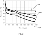
- the graphs provided in FIG. 2 plot temperatures in an enclosed habitation space 100 in the form of a naturally ventilated room, measuring 2.7 m x 2.8 m x 3.4 m, with closed windows and doors vs time during the night.
- Graph 110A plots a temperature near the ceiling 106, at a first height 110 of 250 cm above the floor 104;
- graph 112A plots a temperature near the floor 104, at a second height 112 of 24 cm above the floor 104;
- graph 114A plots a temperature at a third, middle, height 114 between the floor 104 and the ceiling 106 of 135 cm above the floor 104.
- FIG. 2 shows that during the night, when a central heating system connected to the radiator 102 was turned off, between 0 and 770 minutes, the temperatures at each of the first, second and third heights 110, 112, 114 decrease.
- the temperature difference between the first and second heights 110, 112 was around 1.5°C to 2°C.
- Graphs 110B, 112B, 114B, 116B in FIG. 3 respectively plot temperatures at the first height 110, the second height 112, the third height 114, and a fourth height of 60 cm above the floor 104 and above the radiator 102 vs time when the central heating system connected to the radiator 102 was turned on. These temperatures were recorded when the central heating system was turned on in the morning following the night described above in respect of FIG. 2 . The central heating system was turned on between 60 and 95 minutes, and between 230 to 255 minutes, and an air circulation module 118 was turned on between 215 and 375 minutes only.
- the air circulation module 118 which in this illustrative example is part of an air displacement appliance 120 in the form of a Philips AC3033 air purifier, was switched on at 215 minutes to a mode that has a Clean Air Delivery Rate of 290 m 3 /h and a power consumption of 16 W. Prior to 215 minutes, the air circulation module 118 was switched off, and hence was not providing an airflow to the enclosed habitation space 100.
- the airflow provided by the air circulation module 118 reduced a temperature gradient in the enclosed habitation space 100.
- the difference between the temperatures at the first and second heights 110, 112 was observed to decrease from about 1.4°C to about 0.4°C.
- the air temperature at the third, middle, height 114 increased as a result of the air circulation module 118 being turned on.
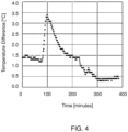
- FIG. 4 provides a graph plotting the difference between the temperatures at the first and second heights 110, 112 vs time over the monitoring period described above in relation to FIG. 3 .
- FIG. 4 shows that the temperature gradient in the enclosed habitation space 100 increased and reached a maximum of about 3.4°C, but with this difference decreasing from about 1.4°C to about 0.4°C following the air circulation module 118 being switched on at 215 minutes.
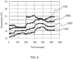
- Graphs 110C, 112C, 122C, 124C in FIG. 5 respectively plot temperature at the first height 110, the second height 112, a fifth height of 69 cm above the floor 104, and a sixth height of 113 cm above the floor in a further illustrative example.
- the heights other than the first height 110 were selected to correspond to ankle, abdomen, and chin height of an adult when sitting on a chair.
- FIG. 6 plots an average of the temperatures at these heights vs time.
- the air circulation module 118 which is part of an air displacement appliance 120 in the form of a Philips AC3033 air purifier, was switched on at 60 to 180 minutes and 300 to 420 minutes to a mode that has a Clean Air Delivery Rate of 160 m 3 /h and a power consumption of 8 W. Prior to the air circulation module 118 being switched on at 60 minutes, the period between 180 and 300 minutes, and after 420 minutes, the air circulation module 118 was switched off, and hence was not providing an airflow. Moreover, the central heating system was set to control the temperature of the enclosed habitation space to 19°C until 180 minutes, and to 20°C between 180 and 420 minutes.
- an air circulation module 118 can enable adjustment, e.g. increase, of air temperature in an enclosed habitation space 100 at body height.
- the precise extent of the body height air temperature adjustment may depend on various factors, such as central heating system settings, room height, room volume, airflow provided by the air circulation module 118, and outdoor weather conditions.
- the greatest benefits may be expected during relatively cold outdoor weather conditions when indoor air may be more polluted due to elevated concentrations of fine particulate matter, e.g. PM2.5, and smog levels, and ingress of such particulate matter into the enclosed habitation space 100.
- the air displacement appliance 120 in the form of the Philips AC3033 air purifier cleaned the air of the room 6.3 times per hour, since the Clean Air Delivery Rate was 160 m 3 /h and the volume of the enclosed habitation space 100 was 25.5 m 3 .
- this cleaning rate further provided relatively rapid removal of aerosol particulates from the enclosed habitation space 100.
- air purification system-comprising air displacement appliances 120 such as portable air purifiers, that comply with air cleaning performance requirements stipulated by national standards or with recommendations for protection against infectious virus aerosols may also be capable of creating more comfortable air temperatures at human body heights within enclosed habitation spaces 100 with volumes for which they are advised.
- conventional air purification system-comprising air displacement appliances 120 and other types of air displacement appliances 120, such as air humidification system- and/or air dehumidification system-comprising air displacement appliances 120, may not be suited to reliably adjust human body height air temperature in a way that minimizes heating costs because they are not responsive to temperature gradients in the enclosed habitation space 100.
- air circulation module 118 of such air displacement appliances 120 can, at least in principle, be operated to provide a relatively high airflow continuously in order to lessen temperature gradients in the enclosed habitation space 100, this may lead to unacceptably high sound levels and elevated energy consumption.
- the present disclosure accordingly provides a system 128 and a method 200 for adjusting airflow provided by the air circulation module 118 to the enclosed habitation space 100.
- the method 200 comprises obtaining 202, via at least one sensor 130, 132, temperature variation data indicative of spatial and/or temporal variation of temperature in the enclosed habitation space 100.
- the method 200 further comprises generating 204 a control signal to adjust the airflow provided by the air circulation module 118 based on the temperature variation data.
- the spatial variation of temperature in the enclosed habitation space 100 may correspond to the above-described temperature gradient in the enclosed habitation space 100.
- a temperature gradient can also result from temporal variation of temperature, for example caused by a heating element 102, e.g. radiator, in the enclosed habitation space 100 being switched on or off, or a set temperature of a central heating system connected to the heating element 102 being changed, as described above in relation to FIGs. 2 to 6 .
- the air circulation module 118 can be operated to efficiently adjust the temperature conditions experienced by an occupant 134 or occupants of the enclosed habitation space 100.
- This control can, for example, enable a body height temperature in the enclosed habitation space 100 to be increased in a way that minimizes energy consumption.
- the system 128 comprises one or more processors 136 configured to implement the method 200 by obtaining 202, via the at least one sensor 130, 132, the temperature variation data indicative of spatial and/or temporal variation of temperature in the enclosed habitation space 100, and generating 204 the control signal for adjusting the airflow provided by the air circulation module 118 based on the temperature variation data.
- Communication of sensory signals from the sensor(s) 130, 132 to the processor(s) 136 is schematically represented in FIG. 1 by the arrows between the blocks denoting the sensor(s) 130, 132 and the block denoting the processor(s) 136.
- This communication can be implemented in any suitable manner, such as via a wired or wireless link between the sensor(s) 130, 132 and the processor(s) 136.
- the processor(s) 136 can be included in the air displacement appliance 120 and/or in an external device, e.g. a smartphone, tablet computer and/or cloud-based server, that is separate from the air displacement appliance 120.
- an external device e.g. a smartphone, tablet computer and/or cloud-based server, that is separate from the air displacement appliance 120.
- the processor(s) 136 may be in communication with further sensor(s) and/or further air circulations system(s), for instance further sensor(s) and/or further air circulations system(s) in further enclosed habitation space(s), e.g. room(s).
- the processor(s) 136 may, for instance, be arranged to create more comfortable environments, e.g. air temperatures at human body heights, within the further enclosed habitation space(s) in addition to the enclosed habitation space 100.
- the processor(s) 136 may be in communication with, and thus may be configured to control, further air displacement appliance(s), such as air purification system-comprising air displacement appliance(s), humidification and/or dehumidification system-comprising air displacement appliance(s), fragrance emitting unit-comprising air displacement appliance(s), etc.
- further air displacement appliance(s) such as air purification system-comprising air displacement appliance(s), humidification and/or dehumidification system-comprising air displacement appliance(s), fragrance emitting unit-comprising air displacement appliance(s), etc.
- the system 128 includes one or more user interfaces, for instance user interface(s) included in the air displacement appliance 120 and/or in an external device, e.g. a smartphone, tablet computer, that is separate from the air displacement appliance 120.
- user interfaces for instance user interface(s) included in the air displacement appliance 120 and/or in an external device, e.g. a smartphone, tablet computer, that is separate from the air displacement appliance 120.
- Such user interface(s) may be configured to communicate data to the user, for instance data relating to the conditions in the enclosed habitation space 100, and/or may be configured to receive user command(s) for controlling the air displacement appliance(s) 120 and, in some embodiments, the heating system connected to the heating element 102.
- the processor(s) 136 may receive the user command(s) and control the air displacement appliance(s) 120, and optionally the heating system, based on the user command(s).
- the at least one sensor 130, 132 can be of any suitable type provided that the temperature variation data can be provided or derived from sensory signals generated by the at least one sensor 130, 132.
- the at least one sensor 130, 132 comprises a temperature sensor, e.g. a thermocouple.
- the at least one sensor 130, 132 may comprise a humidity sensor.
- the at least one sensor 130, 132 may detect temperature and humidity.
- the at least one sensor 130, 132 may include, or be, a relative humidity sensor that detects temperature and humidity.
- the temperature sensor can be regarded as a sensor whose sensory signal, e.g. voltage signal, generation is directly responsive to a temperature in the enclosed habitation space 100.
- the relative humidity sensor can be regarded as a sensor whose sensory signal, e.g. voltage signal, generation is directly responsive to a relative humidity in the enclosed habitation space 100.
- the at least one sensor 130, 132 is included in, e.g. is supplied to the user as part of, the system 128.
- the at least one sensor 130, 132 may include one or more remote sensors (not visible) spatially removed from the air displacement appliance 120 but in communication with the processor(s) 136 so that the processor(s) 136 is or are able to obtain the temperature variation data via the one or more remote sensors.
- Such remote sensor(s) may be positionable in the enclosed habitation space 100 in location(s) in the enclosed habitation space 100 that facilitate obtaining of the temperature variation data, and also monitoring of the effect of the air circulation module 118 on the spatial and/or temporal temperature variation in the enclosed habitation space 100.
- the at least one sensor 130, 132 may comprise a sensor included in, e.g. integrated into, the air displacement appliance 120.
- the at least one sensor may include a temperature sensor that is included in an air pollutant level sensing system for providing temperature dependence correction of a pollutant-related signal response.
- systems 128 and methods 200 of the present disclosure may employ sensing functionality that is already incorporated into the air displacement appliance 120.
- the at least one sensor 130, 132 comprises a first sensor 130 arranged at a height in the enclosed habitation space 100, and a second sensor 132 arranged at a further height in the enclosed habitation space 100, with the height and the further height being different from each other.
- the temperature variation data obtained via the first sensor 130 and the second sensor 132 may be indicative of a temperature difference between at the height and at the further height.
- the first and second sensors 130, 132 may assist to provide data indicative of a temperature gradient along a height dimension, in other words between the floor 104 and the ceiling 106, of the enclosed habitation space 100. This may provide a particularly reliable basis on which to adjust the airflow provided by the air circulation module 118.
- control signal may increase the airflow based on the temperature difference between at the height and at the further height equaling or exceeding a given, e.g. predetermined, threshold.
- greater air circulation may be provided to reduce the temperature gradient along the height dimension in the enclosed habitation space 100.
- control signal may decrease the airflow based on the temperature difference between at the height and at the further height equaling or being below a further given, e.g. predetermined, threshold.
- the first and second sensors 130, 132 are mounted at different heights relative to each other on the air displacement appliance 120.
- the mounting of the first and second sensors 130, 132 at the height and at the further height respectively may be implemented simply by the mounting of the first and second sensors 130, 132 in the air displacement appliance 120. This may provide a particularly reliable basis on which to adjust the airflow provided by the air circulation module 118, especially in the case of relatively tall air displacement appliances 120.
- one of the first and second sensors 130, 132 may be mounted at or proximal to a top of the air displacement appliance 120 when the air displacement appliance 120 is orientated for use, with the other of the first and second sensors 132, 130 being mounted at or proximal to a bottom of the air displacement appliance 120.
- proximal to a top of the air displacement appliance 120 may mean that the respective sensor 130, 132 is closer to the top of the air displacement appliance 120 than to the bottom of the air displacement appliance 120.
- the sensor of the first and second sensors 130, 132 that is mounted proximal to the top of the air displacement appliance 120 may be mounted at most 10 cm, e.g. about 5 cm, below the top of the air displacement appliance 120.
- proximal to a bottom of the air displacement appliance 120 may mean that the respective sensor 130, 132 is closer to the bottom of the air displacement appliance 120 than to the top of the air displacement appliance 120.
- the sensor of the first and second sensors 130, 132 that is mounted proximal to the bottom of the air displacement appliance 120 may be mounted at most 10 cm, e.g. about 3 cm, above the bottom of the air displacement appliance 120.
- the at least one sensor 130, 132 may be mounted at location(s) of the air displacement appliance 120 other than at/proximal to the top and at/proximal to the bottom of the air displacement appliance 120.
- the at least one sensor 130, 132 may be mounted at/proximal to the front side and/or at/proximal to the back side of the air displacement appliance 120.
- the at least one sensor 130, 132 may be mounted outside and/or inside the air displacement appliance 120.
- the air displacement appliance 120 includes a heating element-facing portion for facing, in use, the heating element 102 provided in the enclosed habitation space 100.
- Such a heating element-facing portion can be indicated in any suitable manner.
- the heating element-facing portion is indicated by a sign provided on the air displacement appliance 120 and/or in instructions provided for the air displacement appliance 120.
- the at least one sensor 130, 132 may include a sensor 132 mounted at the heating element-facing portion.
- the sensor mounted at the heating element-facing portion may be included in, e.g. define, the first sensor 130 or the second sensor 132.
- the sensor 132 mounted at the heating element-facing portion may be included in, e.g. define, the sensor of the first and second sensors 130, 132, mounted at an elevated position relative to the other of the first and second sensors 132, 130.
- the elevated sensor 132 may be directed towards the heating element 102.
- This may be a particularly suitable arrangement in the scenario that the heating element 102 is a wall-mounted heating element 102, e.g. radiator.
- the sensor mounted at the heating element-facing portion may be included in, e.g. define, the sensor of the first and second sensors 130, 132, mounted at a lower position relative to the other of the first and second sensors 132, 130.
- heating element 102 is a floor heating element of a floor heating system.
- the air circulation module 118 is preferably located in the enclosed habitation space 100 proximal to the heating element 102, for example within 50 cm, e.g. about 20 cm, from the heating element 102, e.g. radiator.
- the at least one sensor 130, 132 is a single sensor.
- Such a single sensor can nonetheless be used to obtain the temperature variation data.
- the temperature variation data is indicative of a rate of change of temperature in the enclosed habitation space 100.
- Such temperature variation data is obtainable, for instance, via the single sensor.
- the temperature variation data indicative of a rate of change of temperature in the enclosed habitation space 100 is obtainable via more than one sensor included in the at least one sensor 130, 132.
- control signal may increase the airflow based on the rate of change of temperature equaling or exceeding a given, e.g. predetermined, threshold.
- greater air circulation may be provided to reduce the temperature gradient indicated by, e.g. predictable via, the elevated rate of change of temperature.
- control signal increases the airflow, e.g. so as to operate the air circulation module 118 in a more powerful mode, if the temperature variation data obtained using the at least one sensor 130, 132, e.g. the first sensor 130 and/or the second sensor 132, indicates a relatively rapid increase in temperature in the enclosed habitation space 100, for example by more than 1°C within 5 to 10 minutes, e.g. by more than 1°C within 5 or 10 minutes.
- control signal may decrease the airflow based on the rate of change of temperature equaling or being below a further given, e.g. predetermined, threshold.
- control signal decreases the airflow, e.g. so as to operate the air circulation module 118 in a less powerful mode or to deactivate the air circulation module 118, if the temperature variation data obtained using the at least one sensor 130, 132, e.g. the first sensor 130 and/or the second sensor 132, indicates stabilization of the temperature in the enclosed habitation space 100.
- Such stabilization is, for example, indicated by the temperature changing by less than 1°C during 20 to 40 minutes, e.g. by less than 1°C within 20 or 40 minutes.
- the adjusted airflow provided as a result of the temperature variation data-based control signal may be provided, e.g. may continue, irrespective of maintenance or improvement of air quality, for instance as determined via a sensed particulate matter level and/or CO 2 level and/or formaldehyde level and/or other gaseous pollutant level, in the enclosed habitation space 100.
- the processor(s) 136 may be configured to control the air circulation module 118 to maintain the airflow based on the temperature variation data irrespective of the processor(s) receiving air quality data indicative of air quality in the enclosed habitation space 100 being such as to justify, without accounting for the temperature variation data, decreasing the airflow.
- the air circulation module 118 may be controlled to continue operating in, for instance, a more powerful operation mode even if the air quality reaches an acceptable level, e.g. as determined by a particulate matter level and/or CO 2 level and/or formaldehyde level and/or other gaseous pollutant level having a sufficiently low value, that would require no further purification of the air in the enclosed habitation space 100.
- an acceptable level e.g. as determined by a particulate matter level and/or CO 2 level and/or formaldehyde level and/or other gaseous pollutant level having a sufficiently low value, that would require no further purification of the air in the enclosed habitation space 100.
- This operation of the air circulation module 118 may be continued until, for instance, the at least one sensor 130, 132, e.g. the first sensor 130 and/or the second sensor 132, indicates stabilization of the temperature in the enclosed habitation space 100.
- Such stabilization is, for example, indicated by the temperature changing by less than 1°C during 20 to 40 minutes.
- the air circulation module 118 is controlled to provide an airflow different from that initially provided based on the temperature variation data based on one or more of the following: when subsequent temperature variation data is indicative of a temperature gradient in the enclosed habitation space 100 stabilizing or starting to decrease; after a set time, e.g. from starting the initially provided airflow; based on sensory data indicating that occupants 134 have left the enclosed habitation space 100; and based on data from air pollutant sensor(s).
- the air circulation module 118 is controlled to provide a more powerful airflow, relative to that initially provided based on the temperature variation data, based on data from air pollutant sensor(s).
- the air circulation module 118 can have any suitable design provided that the airflow, in other words active airflow, provided by the air circulation module 118 can be adjusted by the control signal, e.g. to increase and/or decrease circulation in the enclosed habitation space 100.
- the air circulation module 118 comprises a fan 138 whose rotation provides the airflow.
- the fan 138 can be driven by a motor 140 that is also included in the air circulation module 118.
- the motor 140 may be controlled by the control signal to increase and/or decrease the rotational speed of the fan 138 in order to increase and/or decrease the airflow provided by the air circulation module 118.
- Communication of the control signal from the processor(s) 136, generated based on the temperature variation data, to the air circulation module 118 is schematically represented in FIG. 1 by the arrow between the block denoting the processor(s) 136 and the block denoting the motor 140.
- This communication can be implemented in any suitable manner, such as via a wired or wireless link between the processor(s) 136 and the air circulation module 118, e.g. between the processor(s) 136 and the motor 140.
- the air circulation module 118 may include a module configured to create an airflow by means of ionizing and accelerating air components in an electrostatic field.
- Such a module may be regarded as implementing so-called "ionic wind technology”.
- the airflow generated by the air circulation module 118 may, for instance, be generated between an air inlet 142 and an air outlet 144 of the air displacement appliance 120.
- any suitable spatial arrangement of the air inlet 142 and the air outlet 144 can be contemplated.
- the air inlet 142 is arranged at a side of the air displacement appliance 120, with the air outlet 144 being arranged at the top of the air displacement appliance 120.
- the air displacement appliance 120 can be any type of air displacement appliance 120.
- the air displacement appliance 120 comprises an air purification system 146 arranged to purify air in the enclosed habitation space 100.
- the air circulation module 118 may cooperate with the air purification system 146 such that the airflow provided into the enclosed habitation space 100 is purified by the air purification system 146.
- the air purification system 146 may include one or more purification modules configured to remove particulate and/or gaseous pollutants from the air.
- Such purification modules may use one or more technologies that are known to the skilled person, such as one or more of the following: HEPA filter(s); electrostatic precipitator(s); ionizer(s); activated carbon filter(s), e.g. activated carbon filter(s) containing chemical additive(s); gas adsorption and/or conversion filter(s) that contain non-activated carbon material(s), such as metal oxide catalysts, and noble metal catalysts, silicas and/or zeolites; photocatalytic oxidation module(s), e.g. photocatalytic oxidation modules that contain UV- or visible-light source(s); plasma unit(s); and aerosol inactivation module(s) that generate far-UV, UV-C or radiation from other wavelengths.
- HEPA filter(s) e.g. activated carbon filter(s) containing chemical additive(s)
- gas adsorption and/or conversion filter(s) that contain non-activated carbon material(s), such as metal oxide catalysts, and noble metal catalysts,
- the air purification system 146 includes, e.g. in addition to one or more of the above-mentioned purification modules, one or more of the following: sensor(s) configured to measure the levels of PM1, PM2.5, PM10, formaldehyde, BTX, TVOC, NO 2 , CO 2 and/or other air pollutants known to the skilled person; sensor(s) configured to measure the presence of person(s) in the enclosed habitation space 100, e.g. by detecting movement, sound, vibrations, CO 2 levels, etc.; automatic mode(s) that respond to pollutant levels in indoor and/or outdoor air; a dehumidification module; and a humidification module.
- sensor(s) configured to measure the levels of PM1, PM2.5, PM10, formaldehyde, BTX, TVOC, NO 2 , CO 2 and/or other air pollutants known to the skilled person
- sensor(s) configured to measure the presence of person(s) in the enclosed habitation space 100, e.g. by detecting movement, sound,
- the air displacement appliance 120 may include one or more of an air humidification system arranged to humidify air in the enclosed habitation space 100; an air dehumidification system arranged to dehumidify air in the enclosed habitation space 100; and a fragrance emitting unit arranged to emit fragrance into the enclosed habitation space 100.
- the air circulation module 118 may cooperate with the air humidification system and/or the air dehumidification system such that the airflow provided into the enclosed habitation space 100 is humidified or dehumidified.
- the humidification system may be controlled, together with the air circulation module 118, to humidify the airflow based on the temperature variation data.
- the air circulation module 118 may, in such a humidification system-comprising air displacement appliance 120, create an airflow over a water or wetted surface in order to evaporate water. The thus evaporated water may be carried by the airflow into the enclosed habitation space 100.
- the air circulation module 118 may alternatively humidify the air using alternative technologies, such as via ultrasonic nebulizers.
- the temperature variation data may provide an additional advantage in the case of the air displacement appliance 120 including such a humidification system, since activating the humidification system based on the temperature variation data, e.g. when the detected temperature increases or stabilizes, may assist to prevent that the humidification lowers the air temperature to uncomfortable levels. This is because the automatic control based on the temperature variation data may stop or decrease the airflow, and as a consequence also the water evaporation, if the air temperature stabilizes or starts to decrease.
- the air circulation module 118 may cooperate with the fragrance emitting unit such that airflow provided into the enclosed habitation space 100 contains the fragrance.
- the air displacement appliance 120 may be equipped with the sensor(s) 130, 132 even though it may not necessarily contain active cooling or heating elements or an air humidification system which can influence the air temperature in the enclosed habitation space 100.
- an air displacement appliance 120 in the form of a Philips AC3033 air purifier was equipped with first and second temperature sensors 130, 132 that were attached to the outside of the air displacement appliance 120.
- a first temperature sensor 130 was positioned 3 cm above the bottom of the air displacement appliance 120, and a second temperature sensor 132 was positioned 5 cm below the top of the air displacement appliance 120.
- the second temperature sensor 132 was positioned on a heating element-facing portion of the air displacement appliance 120, which heating element-facing portion faced the only heating element 102 provided in the enclosed habitation space 100.
- the first temperature sensor 130 was positioned on a portion of the air displacement appliance opposite to the heating element-facing portion.
- the heating element 102 was a radiator connected to a central heating system.
- the enclosed habitation space 100 was in the form of a naturally ventilated room, measuring 2.7 m x 2.8 m x 3.4 m, with closed windows and doors.
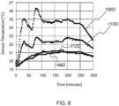
- the air displacement appliance 120 was placed 20 cm in front of the heating element 102 in the form of the radiator, and, referring to FIG. 8 , the air circulation module 118 of the air displacement appliance 120 was switched off between -60 and 30 minutes, switched on to "Speed 1" at 30 to 180 minutes, and switched off between 180 and 300 minutes. Moreover, the central heating system was set to control the temperature of the enclosed habitation space 100 to 20°C between 0 and 275 minutes, and to 16°C between 275 and 300 minutes.
- Graphs 110D, 112D, 148D, 150D in FIG. 8 respectively plot temperatures at the first height 110 and 2.5 m away from the heating element 102, the second height 112 and 2.5 m away from the heating element 102, the position of the first temperature sensor 130, and the position of the second temperature sensor 132 vs time.
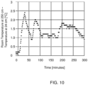
- FIG. 10 plots the difference between the temperatures at the first and second heights 110, 112 vs time over the monitoring period described above in relation to FIGs. 8 and 9 .
- the first temperature sensor 130 positioned at or proximal to the bottom of the air displacement appliance 120 may show a larger and faster temperature change.
- the automatic adjustment of the air circulation module 118 provided by the control signal generated by the processor(s) 136 may be more likely to be based on, e.g. triggered by, sensory signals from the first temperature sensor 130.
- the air circulation module 118 may increase the air temperature at body height in the enclosed habitation space 100.
- the testing was carried out at the end of the spring period (April 30 - May 4), and the increase in the air temperature at body height was about 1°C.
- the precise extent of the body height air temperature adjustment may depend on various factors, such as central heating system settings, room height, room volume, airflow rate provided by the air circulation module 118, and outdoor weather conditions, such as outdoor temperature, wind strength and wind direction.
- adjustment of the airflow provided by the air circulation module 118 based on the temperature variation data may be identified at a laboratory with equipment that is used for common air purifier performance tests as described in standards like GB T 18801-2015 or ANSI-AHAM-AC-1.
- the identification may involve verifying if a given system 128 or air displacement appliance 120 includes a sensor or sensors 130, 132 that can be used to obtain the temperature variation data, such as a temperature sensor and/or a relative humidity sensor. If so, the system 128 or air displacement appliance 120 may be arranged next to a heating element 102, e.g.
- the above test can be carried out in 30 m 3 test chambers that are used for air purifier performance tests according to Chinese testing standards (and similar tests according to US and upcoming IEC standards).
- the present disclosure can be applied, for example, in control of portable air purifiers for residential spaces, classrooms, offices and similarly sized indoor spaces; in control of air purifiers with a humidification module for the same indoor spaces; in fan-based humidifiers for the same indoor spaces that do not contain air purification modules; and fans for the same indoor spaces that do not purify nor humidify the air.
- processors 136 can be implemented in numerous ways, with software and/or hardware, to perform the various functions required.
- the processor(s) 136 may, for example, employ one or more microprocessors programmed using software (e.g., microcode) to perform the required functions.
- microprocessors programmed using software (e.g., microcode) to perform the required functions.
- processor components include, but are not limited to, conventional microprocessors, application specific integrated circuits (ASICs), and field-programmable gate arrays (FPGAs).
- the one or more processors 136 may be associated with one or more storage media such as volatile and non-volatile computer memory such as RAM, PROM, EPROM, and EEPROM.
- the storage media may be encoded with one or more programs that, when executed on one or more processors 136 and/or controllers, perform the required functions.
- Various storage media may be fixed within a processor or controller or may be transportable, such that the one or more programs stored thereon can be loaded into the one or more processors 136.
- a single processor or other unit may fulfill the functions of several items recited in the claims.
- a computer program may be stored/distributed on a suitable medium, such as an optical storage medium or a solid-state medium supplied together with or as part of other hardware, but may also be distributed in other forms, such as via the Internet or other wired or wireless telecommunication systems.
- a suitable medium such as an optical storage medium or a solid-state medium supplied together with or as part of other hardware, but may also be distributed in other forms, such as via the Internet or other wired or wireless telecommunication systems.
Landscapes
- Engineering & Computer Science (AREA)
- Chemical & Material Sciences (AREA)
- Combustion & Propulsion (AREA)
- Mechanical Engineering (AREA)
- General Engineering & Computer Science (AREA)
- Physics & Mathematics (AREA)
- Fluid Mechanics (AREA)
- Air Conditioning Control Device (AREA)
Abstract
Provided is a method for adjusting airflow provided by an air circulation module (118), e.g. a portable air circulation module, to an enclosed habitation space (100). The method comprises obtaining, via at least one sensor (130, 132), temperature variation data indicative of spatial and/or temporal variation of temperature in the enclosed habitation space. The airflow provided by the air circulation module is adjusted by a control signal that is generated according to the temperature variation data. Further provided is a system (128) for adjusting airflow provided by such an air circulation module, e.g. portable air circulation module, to an enclosed habitation space, an air displacement appliance comprising the system and the air circulation module, and a computer program for implementing the method.
Description
- This invention relates to a method and system for adjusting airflow provided by an air circulation module to an enclosed habitation space. Examples of enclosed habitation spaces include a residential indoor space, e.g. a room in a private house or apartment, a classroom, an office or a waiting room. The invention further relates to a computer program for implementing the method.
- In wintertime, heating costs are high because of cold outdoor weather. Due to increasing energy costs and climate change, there is a need for solutions that create comfortable indoor environments at lower power consumptions and reduced CO2 emissions.
- One such solution is so-called thermal destratification. This is a technology that mixes higher temperature air from an upper part of an indoor space with colder air from a lower part of the space (see, e.g., Aynsley, Richard "Circulating fans for summer and winter comfort and indoor energy efficiency" Environment Design Guide (2007): 1-10). As a result of this mixing, the temperature at human body height is raised without additional heating costs. To this end, fans are typically mounted in upper parts of tall indoor public spaces, such as conference areas, halls, etc.
- Portable air purification systems are devices that generate an airflow through purification modules which remove or convert air pollutants. Examples of purification modules include HEPA and activated carbon filters. The performance of an air purification system is commonly expressed as the Clean Air Delivery Rate (CADR) which is defined by the airflow delivered through the purification module multiplied by the pollutant removal/conversion efficiency.
- In order to offer protection against virus aerosols in poorly ventilated rooms, air purification systems are recommended to have a CADR that equals three to six times the room volume. At such high airflows, the air in the room is intensively mixed, which can lead to small gradients of pollutant levels throughout the room.
- Portable air purification systems are increasingly used to remove particulate and volatile pollutants from the indoor air. These pollutants can be created indoors, for example during cooking or by outgassing of new decoration, but can also enter the indoor air from outdoors as fine dust and smog gases that penetrate into the home, even when windows and doors are closed.
- During wintertime, outdoor pollutant levels are typically higher because of increased emissions from power plants and wood burning activities. In this respect, reference is made to, for example, Chafe, Zoë, et al. "Residential heating with wood and coal: health impacts and policy options in Europe and North America" 2015, World Health Organization Regional Office Europe; and Saraga, D., et al. "Multi-city comparative PM2. 5 source apportionment for fifteen sites in Europe: The ICARUS project" Science of The Total Environment 751 (2021): 141855. As a consequence, especially during wintertime there can be an increased need for portable air purification systems, in addition to the above-mentioned need for solutions that create comfortable indoor environments at lower power consumptions and reduced CO2 emissions.
- The invention is defined by the claims.
- According to examples in accordance with an aspect of the invention, there is provided a method for adjusting airflow provided by an air circulation module to an enclosed habitation space, the method comprising: obtaining, via at least one sensor, temperature variation data indicative of spatial and/or temporal variation of temperature in the enclosed habitation space; and generating, based on the temperature variation data, a control signal for controlling the air circulation module to adjust the airflow.
- The enclosed habitation space is, for example, a residential indoor space, e.g. a room in a private house or apartment, a classroom, an office or a waiting room.
- The present invention is partly based on the realization that an air circulation module, e.g. a portable air circulation module, can be employed to create more comfortable indoor environments, particularly in wintertime, with lower overall power consumption.
- The spatial variation of temperature in the enclosed habitation space may correspond to a temperature gradient in the enclosed habitation space. Such a temperature gradient can also result from temporal variation of temperature, for example caused by a heating element, e.g. radiator, in the enclosed habitation space being switched on or off, or a set temperature of a central heating system connected to the heating element being changed.
- By generating the control signal to adjust the airflow provided by the air circulation module based on the temperature variation data indicative of the spatial and/or temporal variation of temperature in the enclosed habitation space, the air circulation module can be operated to efficiently adjust the temperature conditions experienced by an occupant or occupants of the enclosed habitation space.
- This control can, for example, enable a body height temperature in the enclosed habitation space to be increased in a way that minimizes energy consumption.
- In some embodiments, the temperature variation data is indicative of a rate of change of temperature in the enclosed habitation space. Such temperature variation data is obtainable, for instance, via a single sensor.
- In such embodiments, the control signal may increase the airflow based on the rate of change of temperature equaling or exceeding a given, e.g. predetermined, threshold.
- Thus, greater airflow may be provided to reduce the temperature gradient indicated by, e.g. predictable via, the elevated rate of change of temperature.
- The control signal may increase the airflow, e.g. so as to operate the air circulation module in a more powerful mode, if the temperature variation data obtained using the at least one sensor indicates a relatively rapid increase in temperature in the enclosed habitation space, for example by more than 1°C within 5 to 10 minutes.
- Alternatively or additionally, the control signal may decrease the airflow based on the rate of change of temperature equaling or being below a further given, e.g. predetermined, threshold.
- Thus, lower airflow, for instance no airflow, may be provided by the air circulation module should this be warranted by the rate of change of temperature being sufficiently low. This may assist to reduce energy consumption.
- The control signal may decrease the airflow, e.g. so as to operate the air circulation module in a less powerful mode or to deactivate the air circulation module, if the temperature variation data obtained using the at least one sensor indicates stabilization of the temperature in the enclosed habitation space.
- Such stabilization is, for example, indicated by the temperature changing by less than 1°C during 20 to 40 minutes.
- In some embodiments, the at least one sensor comprises a first sensor arranged at a height in the enclosed habitation space, and a second sensor arranged at a further height in the enclosed habitation space, with the height and the further height being different from each other.
- In such embodiments, the temperature variation data obtained via the first sensor and the second sensor may be indicative of a temperature difference between at the height and at the further height.
- Thus, the first and second sensors may assist to provide data indicative of a temperature gradient along a height dimension, in other words between a floor and a ceiling, of the enclosed habitation space.
- This may provide a particularly reliable basis on which to adjust the airflow provided by the air circulation module.
- In some embodiments, the control signal may increase the airflow based on the temperature difference between at the height and at the further height equaling or exceeding a given, e.g. predetermined, threshold.
- Thus, greater air circulation may be provided to reduce the temperature gradient along the height dimension in the enclosed habitation space.
- Alternatively or additionally, the control signal may decrease the airflow based on the temperature difference between at the height and at the further height equaling or being below a further given, e.g. predetermined, threshold.
- Thus, lower airflow, for instance no airflow, may be provided by the air circulation module should this be warranted by the temperature difference being sufficiently low. This may assist to reduce energy consumption.
- It is noted, more generally, that in embodiments in which the air circulation module is included in an air displacement appliance having an air purification system, the adjusted airflow provided as a result of the temperature variation data-based control signal may be provided, e.g. may continue, irrespective of the need to maintain or improve indoor air quality, for instance as determined via a sensed particulate matter level and/or CO2 level and/or formaldehyde level and/or other gaseous pollutant level, in the enclosed habitation space.
- According to another aspect there is provided a system for adjusting airflow provided by an air circulation module to an enclosed habitation space, the system comprising one or more processors configured to: obtain, via at least one sensor, temperature variation data indicative of spatial and/or temporal variation of temperature in the enclosed habitation space; and generate, based on the temperature variation data, a control signal for controlling the air circulation module to adjust the airflow
- In some embodiments, the at least one sensor is included in, e.g. is supplied to the user as part of, the system.
- The at least one sensor may include one or more remote sensors spatially removed from the air displacement appliance but in communication with the processor(s) so that the processor(s) is or are able to obtain the temperature variation data via the one or more remote sensors.
- Such remote sensor(s) may be positionable in the enclosed habitation space in location(s) in the enclosed habitation space that facilitate obtaining of the temperature variation data, and also monitoring of the effect of the adjusted airflow provided by the air circulation module on the spatial and/or temporal temperature variation in the enclosed habitation space.
- Alternatively or additionally, the at least one sensor may be included, e.g. mounted, in an air displacement appliance that includes the air circulation module.
- In some embodiments, the temperature variation data is indicative of a rate of change of temperature in the enclosed habitation space. As also described above in relation to the method, the control signal may increase the airflow based on the rate of change of temperature equaling or exceeding a given threshold.
- In some embodiments, the at least one sensor comprises a first sensor arranged at a height in the enclosed habitation space, and a second sensor arranged at a further height in the enclosed habitation space, with the height and the further height being different from each other. The temperature variation data may be indicative of a temperature difference between at the height and at the further height.
- In some embodiments, the control signal increases the airflow based on the temperature difference equaling or exceeding a given threshold, as also previously described in relation to the method.
- The processor(s) may be configured to control the air circulation module to maintain the airflow based on the temperature variation data irrespective of the processor(s) receiving air quality data indicative of air quality in the enclosed habitation space being such as to justify, without accounting for the temperature variation data, decreasing the airflow.
- In some embodiments, the air circulation module is controlled by the processor(s) to continue operating in, for instance, a more powerful operation mode even if the air quality reaches an acceptable level, e.g. as determined by a particulate matter level and/or CO2 level and/or formaldehyde level and/or other gaseous pollutant level having a sufficiently low value, that would require no further purification of the air in the enclosed habitation space.
- This operation of the air circulation module may be continued until, for instance, the at least one sensor, e.g. the first sensor and/or the second sensor, indicates stabilization of the temperature in the enclosed habitation space.
- Such stabilization is, for example, indicated by the temperature changing by less than 1°C during 20 to 40 minutes.
- In some embodiments, the air circulation module is controlled by the processor(s) to provide an airflow different from that initially provided based on the temperature variation data based on one or more of the following: when subsequent temperature variation data is indicative of a temperature gradient in the enclosed habitation space stabilizing or starting to decrease; after a set time, e.g. from starting the adjusted airflow; based on sensory data indicating that occupants have left the enclosed habitation space; and based on data from air pollutant sensor(s).
- In some embodiments, the air circulation module is controlled by the processor(s) to provide a more powerful airflow, relative to that initially provided based on the temperature variation data, based on data received by the processor(s) from air pollutant sensor(s).
- According to yet another aspect there is provided an air displacement appliance comprising: an air circulation module for providing an airflow to an enclosed habitation space; and the system according to any of the embodiments described herein, the system being configured to generate, based on the temperature variation data, the control signal for controlling the air circulation module to adjust the airflow.
- In embodiments in which the at least one sensor includes the first sensor and the second sensor, the first sensor may be mounted on the air displacement appliance at a first position, and the second sensor is mounted on the air displacement appliance at a second position different from the first position, with the first and second heights being different from each other due to a difference in height between the first and second positions.
- Thus, the mounting of the first and second sensors at the height and at the further height respectively may be implemented simply by the mounting of the first and second sensors in the air displacement appliance. This may provide a particularly reliable basis on which to adjust the airflow provided by the air circulation module, especially in the case of relatively tall air displacement appliances.
- In such embodiments, one of the first and second sensors may be mounted at or proximal to a top of the air displacement appliance when the air displacement appliance is orientated for use, with the other of the first and second sensors being mounted at or proximal to a bottom of the air displacement appliance.
- The term "proximal to a top of the air displacement appliance" may mean that the respective sensor is closer to the top of the air displacement appliance than to the bottom of the air displacement appliance.
- For example, the sensor of the first and second sensors that is mounted proximal to the top of the air displacement appliance may be mounted at most 10 cm, e.g. about 5 cm, below the top of the air displacement appliance.
- The term "proximal to a bottom of the air displacement appliance" may mean that the respective sensor is closer to the bottom of the air displacement appliance than to the top of the air displacement appliance.
- For example, the sensor of the first and second sensors that is mounted proximal to the bottom of the air displacement appliance may be mounted at most 10 cm, e.g. about 3 cm, above the bottom of the air displacement appliance.
- The at least one sensor may be mounted at location(s) of the air displacement appliance other than at/proximal to the top and at/proximal to the bottom of the air displacement appliance. For example, the at least one sensor may be mounted at/proximal to the front side and/or at/proximal to the back side of the air displacement appliance.
- In some embodiments, the air displacement appliance includes a heating element-facing portion for facing, in use, the heating element provided in the enclosed habitation space.
- Such a heating element-facing portion can be indicated in any suitable manner. In some embodiments, the heating element-facing portion is indicated by a sign provided on the air displacement appliance and/or in instructions provided for the air displacement appliance.
- In such embodiments, the at least one sensor may include a sensor mounted at the heating element-facing portion.
- In embodiments in which the at least one sensor includes the first sensor and the second sensor, the sensor mounted at the heating element-facing portion may be included in, e.g. define, the first sensor or the second sensor.
- In some embodiments, the sensor mounted at the heating element-facing portion may be included in, e.g. define, the sensor of the first and second sensors mounted at an elevated position relative to the other of the first and second sensors.
- In other words, the elevated sensor may be directed towards the heating element.
- This may be a particularly suitable arrangement in the scenario that the heating element is a wall-mounted heating element, e.g. radiator.
- In alternative embodiments, the sensor mounted at the heating element-facing portion may be included in, e.g. define, the sensor of the first and second sensors, mounted at a lower position relative to the other of the first and second sensors.
- This may be a particularly suitable arrangement in the scenario that the heating element is a floor heating element of a floor heating system.
- In some embodiments, the air displacement appliance further comprises one or more of: an air purification system arranged to purify air in the enclosed habitation space; an air humidification system arranged to humidify air in the enclosed habitation space; an air dehumidification system arranged to dehumidify air in the enclosed habitation space; and a fragrance emitting unit arranged to emit fragrance into the enclosed habitation space.
- For an air displacement appliance including a humidification system, the humidification system may be controlled, together with the air circulation module, to humidify the airflow based on the temperature variation data.
- The air circulation module may, in such a humidification system-comprising air displacement appliance, create an airflow over a water or wetted surface in order to evaporate water. The thus evaporated water may be carried by the airflow into the enclosed habitation space.
- The temperature variation data may provide an additional advantage in the case of the air displacement appliance including such a humidification system, since activating the humidification system based on the temperature variation data, e.g. when the detected temperature increases or stabilizes, may assist to prevent that the humidification lowers the air temperature to uncomfortable levels. This is because the automatic control based on the temperature variation data may stop or decrease the airflow, and as a consequence also the water evaporation, if the air temperature stabilizes or starts to decrease. The air circulation module might also humidify the air using alternative technologies, such as via ultrasonic nebulizers.
- According to a further aspect there is provided a computer program comprising computer program code which is configured, when said computer program is run on one or more processors, to cause said one or more processors to implement the method of any of the embodiments described herein.
- One or more non-transitory computer readable media may be provided, which non-transitory computer readable media have a computer program stored thereon, with the computer program comprises computer program code which is configured, when the computer program is run on the one or more processors, to cause the one or more processors to implement the method according to any of the embodiments described herein.
- More generally, embodiments described herein in relation to the method for adjusting airflow provided by an air circulation module to an enclosed habitation space may be applicable to the system and to the computer program, embodiments described herein in relation to the system for adjusting airflow provided by an air circulation module to an enclosed habitation space may be applicable to the method and computer program, and embodiments described herein in relation to the computer program may be applicable to the method and the system.
- These and other aspects will be apparent from and elucidated with reference to the embodiment(s) described hereinafter.
- For a better understanding of the invention, and to show more clearly how it may be carried into effect, reference will now be made, by way of example only, to the accompanying drawings, in which:
-
FIG. 1 schematically depicts an enclosed habitation space in which air is circulated using an air circulation module; -
FIG. 2 provides graphs of temperature at different heights in an enclosed habitation space vs time when the enclosed habitation space is and is not being heated by a single radiator; -
FIG. 3 provides graphs of temperature at different heights in an enclosed habitation space vs time when the enclosed habitation space is and is not being heated by a single radiator and when an airflow is and is not being provided by an air circulation module; -
FIG. 4 provides a graph of a temperature difference between near a ceiling of an enclosed habitation space and near a floor of the enclosed habitation space vs time; -
FIG. 5 provides graphs of temperature at different heights in an enclosed habitation space vs time when the enclosed habitation space is heated by a single radiator at 19°C and 20°C and when an airflow is and is not being provided by an air circulation module; -
FIG. 6 provides a graph of temperature at an average sitting body height in an enclosed habitation space vs time when the enclosed habitation space is heated by a single radiator at 19°C and 20°C and when an airflow is and is not being provided by an air circulation module; -
FIG. 7 provides a flowchart of a method according to an example; -
FIG. 8 provides graphs of temperature at different heights in an enclosed habitation space vs time when the enclosed habitation space is heated by a single radiator at 20°C and 16°C and when an airflow is and is not being provided by an air circulation module; -
FIG. 9 provides a graph showing a correlation between a temperature near to a top of an air displacement appliance and a temperature near to the ceiling of an enclosed habitation space; and -
FIG. 10 provides a graph of a temperature difference between at a height of 250 cm from the floor of the enclosed habitation space and at a height of 24 cm from the floor of the enclosed habitation space vs time when the enclosed habitation space is heated by a single radiator at 20°C and 16°C and when an airflow is and is not being provided by an air circulation module. - The invention will be described with reference to the Figures.
- It should be understood that the detailed description and specific examples, while indicating exemplary embodiments of the apparatus, systems and methods, are intended for purposes of illustration only and are not intended to limit the scope of the invention. These and other features, aspects, and advantages of the apparatus, systems and methods of the present invention will become better understood from the following description, appended claims, and accompanying drawings. It should be understood that the Figures are merely schematic and are not drawn to scale. It should also be understood that the same reference numerals are used throughout the Figures to indicate the same or similar parts.
- Provided is a method for adjusting airflow provided by an air circulation module, e.g. a portable air circulation module, to an enclosed habitation space. The method comprises obtaining, via at least one sensor, temperature variation data indicative of spatial and/or temporal variation of temperature in the enclosed habitation space. The airflow provided by the air circulation module is adjusted by a control signal that is generated according to the temperature variation data. Further provided is a system for adjusting airflow provided by such an air circulation module, e.g. portable air circulation module, to an enclosed habitation space, an air displacement appliance comprising the system and the air circulation module, and a computer program for implementing the method.
-
FIG. 1 shows anenclosed habitation space 100 heated by aheating element 102. Theheating element 102 can, for example, be a radiator, such as a radiator connected to a central heating system. - The
enclosed habitation space 100 is, for instance, a room, such as a residential room in a private house or apartment. Alternatively, theenclosed habitation space 100 may be a classroom or office space. - The
enclosed habitation space 100 is delimited by afloor 104, aceiling 106, and sidewall(s) 108. The sidewall(s) 108 surround(s) the enclosed habitation space and extend(s) between thefloor 104 and theceiling 106. - It is noted that closable door(s) and/or window(s) (not visible) may be provided in one or more of the
floor 104, theceiling 106 and the sidewall(s) 108. - It has been found that significant temperature differences may exist between upper and lower parts of the
enclosed habitation space 100, even in a residential room of a private house or apartment. - The graphs provided in
FIG. 2 plot temperatures in anenclosed habitation space 100 in the form of a naturally ventilated room, measuring 2.7 m x 2.8 m x 3.4 m, with closed windows and doors vs time during the night.Graph 110A plots a temperature near theceiling 106, at afirst height 110 of 250 cm above thefloor 104; graph 112A plots a temperature near thefloor 104, at asecond height 112 of 24 cm above thefloor 104; andgraph 114A plots a temperature at a third, middle,height 114 between thefloor 104 and theceiling 106 of 135 cm above thefloor 104. -
FIG. 2 shows that during the night, when a central heating system connected to theradiator 102 was turned off, between 0 and 770 minutes, the temperatures at each of the first, second andthird heights second heights -
Graphs FIG. 3 respectively plot temperatures at thefirst height 110, thesecond height 112, thethird height 114, and a fourth height of 60 cm above thefloor 104 and above theradiator 102 vs time when the central heating system connected to theradiator 102 was turned on. These temperatures were recorded when the central heating system was turned on in the morning following the night described above in respect ofFIG. 2 . The central heating system was turned on between 60 and 95 minutes, and between 230 to 255 minutes, and anair circulation module 118 was turned on between 215 and 375 minutes only. - The
air circulation module 118, which in this illustrative example is part of anair displacement appliance 120 in the form of a Philips AC3033 air purifier, was switched on at 215 minutes to a mode that has a Clean Air Delivery Rate of 290 m3/h and a power consumption of 16 W. Prior to 215 minutes, theair circulation module 118 was switched off, and hence was not providing an airflow to theenclosed habitation space 100. - It is evident from
FIG. 3 that the airflow provided by theair circulation module 118 reduced a temperature gradient in theenclosed habitation space 100. After turning on theair circulation module 118 at 215 minutes, the difference between the temperatures at the first andsecond heights height 114 increased as a result of theair circulation module 118 being turned on. -
FIG. 4 provides a graph plotting the difference between the temperatures at the first andsecond heights FIG. 3 .FIG. 4 shows that the temperature gradient in theenclosed habitation space 100 increased and reached a maximum of about 3.4°C, but with this difference decreasing from about 1.4°C to about 0.4°C following theair circulation module 118 being switched on at 215 minutes. -
Graphs FIG. 5 respectively plot temperature at thefirst height 110, thesecond height 112, a fifth height of 69 cm above thefloor 104, and a sixth height of 113 cm above the floor in a further illustrative example. The heights other than thefirst height 110 were selected to correspond to ankle, abdomen, and chin height of an adult when sitting on a chair.FIG. 6 plots an average of the temperatures at these heights vs time. In this further illustrative example, theair circulation module 118, which is part of anair displacement appliance 120 in the form of a Philips AC3033 air purifier, was switched on at 60 to 180 minutes and 300 to 420 minutes to a mode that has a Clean Air Delivery Rate of 160 m3/h and a power consumption of 8 W. Prior to theair circulation module 118 being switched on at 60 minutes, the period between 180 and 300 minutes, and after 420 minutes, theair circulation module 118 was switched off, and hence was not providing an airflow. Moreover, the central heating system was set to control the temperature of the enclosed habitation space to 19°C until 180 minutes, and to 20°C between 180 and 420 minutes. - It is evident from
FIG. 6 that when the central heating system was set to 20°C and 19°C, the airflow provided by theair circulation module 118 increased the average temperature at the sitting body height by about 0.7°C and about 0.3°C respectively. It is noted that theair circulation module 118 had a larger effect when the central heating system was set to 20°C because the temperature gradient in theenclosed habitation space 100 was larger under these conditions. - In the Netherlands and Belgium, independent advisory agencies and authorities claim that reducing the set temperature of a central heating system by 1°C results in a reduction of heating costs by approximately 6 to 7% (Bespaartips verwarming; Milieu Centraal, as of 19 May 2022, Besparen op uw energieverbruik | Vlaanderen.be). Hence the above-mentioned increase of air temperature at the sitting body height of about 0.7°C may deliver a significant reduction in energy costs.
- The above-described illustrative examples show that an
air circulation module 118 can enable adjustment, e.g. increase, of air temperature in anenclosed habitation space 100 at body height. - It is noted that the precise extent of the body height air temperature adjustment may depend on various factors, such as central heating system settings, room height, room volume, airflow provided by the
air circulation module 118, and outdoor weather conditions. - The greatest benefits may be expected during relatively cold outdoor weather conditions when indoor air may be more polluted due to elevated concentrations of fine particulate matter, e.g. PM2.5, and smog levels, and ingress of such particulate matter into the
enclosed habitation space 100. - In the above-described illustrative example whose results are graphically presented in
FIGs. 5 and6 , theair displacement appliance 120 in the form of the Philips AC3033 air purifier cleaned the air of the room 6.3 times per hour, since the Clean Air Delivery Rate was 160 m3/h and the volume of theenclosed habitation space 100 was 25.5 m3. Hence, as well as adjusting, in this case increasing, the body height air temperature, this cleaning rate further provided relatively rapid removal of aerosol particulates from theenclosed habitation space 100. - In relation to removal of aerosol particulates, reference is made to, for example, Asbach, C., et al. "Position paper of the Gesellschaft für Aerosolforschung on understanding the role of aerosol particles in SARS-CoV-2 infection" 2021; United States Environmental Protection Agency "Residential Air Cleaners: A Technical Summary", 3rd edition, August 2018, Portable Air Cleaners, Furnace and HVAC Filters; and Shaughnessy, R. J., and R. G. Sextro "What is an effective portable air cleaning device? A review" Journal of Occupational and Environmental Hygiene 3.4 (2006): 169-181.
- Hence air purification system-comprising
air displacement appliances 120, such as portable air purifiers, that comply with air cleaning performance requirements stipulated by national standards or with recommendations for protection against infectious virus aerosols may also be capable of creating more comfortable air temperatures at human body heights withinenclosed habitation spaces 100 with volumes for which they are advised. - However, conventional air purification system-comprising
air displacement appliances 120, and other types ofair displacement appliances 120, such as air humidification system- and/or air dehumidification system-comprisingair displacement appliances 120, may not be suited to reliably adjust human body height air temperature in a way that minimizes heating costs because they are not responsive to temperature gradients in theenclosed habitation space 100. - Whilst the
air circulation module 118 of suchair displacement appliances 120 can, at least in principle, be operated to provide a relatively high airflow continuously in order to lessen temperature gradients in theenclosed habitation space 100, this may lead to unacceptably high sound levels and elevated energy consumption. - It is also noted that whilst conventional air purification system-comprising
air displacement appliances 120 tend to be equipped with sensors in order to respond automatically to poor air quality situations, suchair displacement appliances 120 may not be responsive to temperature gradients in theenclosed habitation space 100. - Referring to
FIGs. 1 and7 , the present disclosure accordingly provides asystem 128 and amethod 200 for adjusting airflow provided by theair circulation module 118 to theenclosed habitation space 100. - The
method 200 comprises obtaining 202, via at least onesensor enclosed habitation space 100. Themethod 200 further comprises generating 204 a control signal to adjust the airflow provided by theair circulation module 118 based on the temperature variation data. - The spatial variation of temperature in the
enclosed habitation space 100 may correspond to the above-described temperature gradient in theenclosed habitation space 100. Such a temperature gradient can also result from temporal variation of temperature, for example caused by aheating element 102, e.g. radiator, in theenclosed habitation space 100 being switched on or off, or a set temperature of a central heating system connected to theheating element 102 being changed, as described above in relation toFIGs. 2 to 6 . - By generating 204 the control signal to adjust the airflow provided by the
air circulation module 118 based on the temperature variation data indicative of the spatial and/or temporal variation of temperature in theenclosed habitation space 100, theair circulation module 118 can be operated to efficiently adjust the temperature conditions experienced by anoccupant 134 or occupants of theenclosed habitation space 100. - This control can, for example, enable a body height temperature in the
enclosed habitation space 100 to be increased in a way that minimizes energy consumption. - The
system 128 comprises one ormore processors 136 configured to implement themethod 200 by obtaining 202, via the at least onesensor enclosed habitation space 100, and generating 204 the control signal for adjusting the airflow provided by theair circulation module 118 based on the temperature variation data. - Communication of sensory signals from the sensor(s) 130, 132 to the processor(s) 136 is schematically represented in
FIG. 1 by the arrows between the blocks denoting the sensor(s) 130, 132 and the block denoting the processor(s) 136. - This communication can be implemented in any suitable manner, such as via a wired or wireless link between the sensor(s) 130, 132 and the processor(s) 136.
- The processor(s) 136 can be included in the
air displacement appliance 120 and/or in an external device, e.g. a smartphone, tablet computer and/or cloud-based server, that is separate from theair displacement appliance 120. - Alternatively or additionally, the processor(s) 136 may be in communication with further sensor(s) and/or further air circulations system(s), for instance further sensor(s) and/or further air circulations system(s) in further enclosed habitation space(s), e.g. room(s).
- Thus, the processor(s) 136 may, for instance, be arranged to create more comfortable environments, e.g. air temperatures at human body heights, within the further enclosed habitation space(s) in addition to the
enclosed habitation space 100. - Alternatively or additionally, the processor(s) 136 may be in communication with, and thus may be configured to control, further air displacement appliance(s), such as air purification system-comprising air displacement appliance(s), humidification and/or dehumidification system-comprising air displacement appliance(s), fragrance emitting unit-comprising air displacement appliance(s), etc.
- In some embodiments, the
system 128 includes one or more user interfaces, for instance user interface(s) included in theair displacement appliance 120 and/or in an external device, e.g. a smartphone, tablet computer, that is separate from theair displacement appliance 120. - Such user interface(s) may be configured to communicate data to the user, for instance data relating to the conditions in the
enclosed habitation space 100, and/or may be configured to receive user command(s) for controlling the air displacement appliance(s) 120 and, in some embodiments, the heating system connected to theheating element 102. - To this end, the processor(s) 136 may receive the user command(s) and control the air displacement appliance(s) 120, and optionally the heating system, based on the user command(s).
- More generally, the at least one
sensor sensor - In some embodiments, the at least one
sensor - Alternatively or additionally, the at least one
sensor - In some embodiments, the at least one
sensor sensor - The temperature sensor can be regarded as a sensor whose sensory signal, e.g. voltage signal, generation is directly responsive to a temperature in the
enclosed habitation space 100. - The relative humidity sensor can be regarded as a sensor whose sensory signal, e.g. voltage signal, generation is directly responsive to a relative humidity in the
enclosed habitation space 100. - In some embodiments, the at least one
sensor system 128. - The at least one
sensor air displacement appliance 120 but in communication with the processor(s) 136 so that the processor(s) 136 is or are able to obtain the temperature variation data via the one or more remote sensors. - Such remote sensor(s) may be positionable in the
enclosed habitation space 100 in location(s) in theenclosed habitation space 100 that facilitate obtaining of the temperature variation data, and also monitoring of the effect of theair circulation module 118 on the spatial and/or temporal temperature variation in theenclosed habitation space 100. - Alternatively or additionally, the at least one
sensor air displacement appliance 120. - In embodiments in which the
air displacement appliance 120 includes an air purification system, the at least one sensor may include a temperature sensor that is included in an air pollutant level sensing system for providing temperature dependence correction of a pollutant-related signal response. - More generally, the
systems 128 andmethods 200 of the present disclosure may employ sensing functionality that is already incorporated into theair displacement appliance 120. - In some embodiments, such as that shown in
FIG. 1 , the at least onesensor first sensor 130 arranged at a height in theenclosed habitation space 100, and asecond sensor 132 arranged at a further height in theenclosed habitation space 100, with the height and the further height being different from each other. - In such embodiments, the temperature variation data obtained via the
first sensor 130 and thesecond sensor 132 may be indicative of a temperature difference between at the height and at the further height. - Thus, the first and
second sensors floor 104 and theceiling 106, of theenclosed habitation space 100. This may provide a particularly reliable basis on which to adjust the airflow provided by theair circulation module 118. - In some embodiments, the control signal may increase the airflow based on the temperature difference between at the height and at the further height equaling or exceeding a given, e.g. predetermined, threshold.
- Thus, greater air circulation may be provided to reduce the temperature gradient along the height dimension in the
enclosed habitation space 100. - Alternatively or additionally, the control signal may decrease the airflow based on the temperature difference between at the height and at the further height equaling or being below a further given, e.g. predetermined, threshold.
- Thus, lower air circulation, for instance no air circulation, may be provided by the
air circulation module 118 should this be warranted by the temperature difference being sufficiently low. This may assist to reduce energy consumption. - In some embodiments, such as that shown in
FIG. 1 , the first andsecond sensors air displacement appliance 120. - Thus, the mounting of the first and
second sensors second sensors air displacement appliance 120. This may provide a particularly reliable basis on which to adjust the airflow provided by theair circulation module 118, especially in the case of relatively tallair displacement appliances 120. - In such embodiments, one of the first and
second sensors air displacement appliance 120 when theair displacement appliance 120 is orientated for use, with the other of the first andsecond sensors air displacement appliance 120. - The term "proximal to a top of the
air displacement appliance 120" may mean that therespective sensor air displacement appliance 120 than to the bottom of theair displacement appliance 120. - For example, the sensor of the first and
second sensors air displacement appliance 120 may be mounted at most 10 cm, e.g. about 5 cm, below the top of theair displacement appliance 120. - The term "proximal to a bottom of the
air displacement appliance 120" may mean that therespective sensor air displacement appliance 120 than to the top of theair displacement appliance 120. - For example, the sensor of the first and
second sensors air displacement appliance 120 may be mounted at most 10 cm, e.g. about 3 cm, above the bottom of theair displacement appliance 120. - The at least one
sensor air displacement appliance 120 other than at/proximal to the top and at/proximal to the bottom of theair displacement appliance 120. For example, the at least onesensor air displacement appliance 120. - Irrespective of whether the at least one
sensor air displacement appliance 120, the at least onesensor air displacement appliance 120. - In some embodiments, such as that shown in
FIG. 1 , theair displacement appliance 120 includes a heating element-facing portion for facing, in use, theheating element 102 provided in theenclosed habitation space 100. - Such a heating element-facing portion can be indicated in any suitable manner. In some embodiments, the heating element-facing portion is indicated by a sign provided on the
air displacement appliance 120 and/or in instructions provided for theair displacement appliance 120. - In such embodiments, the at least one
sensor sensor 132 mounted at the heating element-facing portion. - In embodiments in which the at least one
sensor first sensor 130 and thesecond sensor 132, the sensor mounted at the heating element-facing portion may be included in, e.g. define, thefirst sensor 130 or thesecond sensor 132. - In some embodiments, such as that shown in
FIG. 1 , thesensor 132 mounted at the heating element-facing portion may be included in, e.g. define, the sensor of the first andsecond sensors second sensors - In other words, the
elevated sensor 132 may be directed towards theheating element 102. This may be a particularly suitable arrangement in the scenario that theheating element 102 is a wall-mountedheating element 102, e.g. radiator. - In alternative embodiments (not visible), the sensor mounted at the heating element-facing portion may be included in, e.g. define, the sensor of the first and
second sensors second sensors - This may be a particularly suitable arrangement in the scenario that the
heating element 102 is a floor heating element of a floor heating system. - It is noted that the
air circulation module 118 is preferably located in theenclosed habitation space 100 proximal to theheating element 102, for example within 50 cm, e.g. about 20 cm, from theheating element 102, e.g. radiator. - In some embodiments, the at least one
sensor - Such a single sensor can nonetheless be used to obtain the temperature variation data.
- In some embodiments, the temperature variation data is indicative of a rate of change of temperature in the
enclosed habitation space 100. Such temperature variation data is obtainable, for instance, via the single sensor. Alternatively, the temperature variation data indicative of a rate of change of temperature in theenclosed habitation space 100 is obtainable via more than one sensor included in the at least onesensor - In such embodiments, the control signal may increase the airflow based on the rate of change of temperature equaling or exceeding a given, e.g. predetermined, threshold.
- Thus, greater air circulation may be provided to reduce the temperature gradient indicated by, e.g. predictable via, the elevated rate of change of temperature.
- For example, the control signal increases the airflow, e.g. so as to operate the
air circulation module 118 in a more powerful mode, if the temperature variation data obtained using the at least onesensor first sensor 130 and/or thesecond sensor 132, indicates a relatively rapid increase in temperature in theenclosed habitation space 100, for example by more than 1°C within 5 to 10 minutes, e.g. by more than 1°C within 5 or 10 minutes. - Alternatively or additionally, the control signal may decrease the airflow based on the rate of change of temperature equaling or being below a further given, e.g. predetermined, threshold.
- Thus, lower airflow, for instance no airflow, may be provided by the
air circulation module 118 should this be warranted by the rate of change of temperature being sufficiently low. This may assist to reduce energy consumption. - For example, the control signal decreases the airflow, e.g. so as to operate the
air circulation module 118 in a less powerful mode or to deactivate theair circulation module 118, if the temperature variation data obtained using the at least onesensor first sensor 130 and/or thesecond sensor 132, indicates stabilization of the temperature in theenclosed habitation space 100. - Such stabilization is, for example, indicated by the temperature changing by less than 1°C during 20 to 40 minutes, e.g. by less than 1°C within 20 or 40 minutes.
- In embodiments in which the
air circulation module 118 is included in anair displacement appliance 120 having an air purification system, the adjusted airflow provided as a result of the temperature variation data-based control signal may be provided, e.g. may continue, irrespective of maintenance or improvement of air quality, for instance as determined via a sensed particulate matter level and/or CO2 level and/or formaldehyde level and/or other gaseous pollutant level, in theenclosed habitation space 100. - For example, the processor(s) 136 may be configured to control the
air circulation module 118 to maintain the airflow based on the temperature variation data irrespective of the processor(s) receiving air quality data indicative of air quality in theenclosed habitation space 100 being such as to justify, without accounting for the temperature variation data, decreasing the airflow. - Thus, the
air circulation module 118 may be controlled to continue operating in, for instance, a more powerful operation mode even if the air quality reaches an acceptable level, e.g. as determined by a particulate matter level and/or CO2 level and/or formaldehyde level and/or other gaseous pollutant level having a sufficiently low value, that would require no further purification of the air in theenclosed habitation space 100. - This operation of the
air circulation module 118 may be continued until, for instance, the at least onesensor first sensor 130 and/or thesecond sensor 132, indicates stabilization of the temperature in theenclosed habitation space 100. - Such stabilization is, for example, indicated by the temperature changing by less than 1°C during 20 to 40 minutes.
- In some embodiments, the
air circulation module 118 is controlled to provide an airflow different from that initially provided based on the temperature variation data based on one or more of the following: when subsequent temperature variation data is indicative of a temperature gradient in theenclosed habitation space 100 stabilizing or starting to decrease; after a set time, e.g. from starting the initially provided airflow; based on sensory data indicating thatoccupants 134 have left theenclosed habitation space 100; and based on data from air pollutant sensor(s). - In some embodiments, the
air circulation module 118 is controlled to provide a more powerful airflow, relative to that initially provided based on the temperature variation data, based on data from air pollutant sensor(s). - The
air circulation module 118 can have any suitable design provided that the airflow, in other words active airflow, provided by theair circulation module 118 can be adjusted by the control signal, e.g. to increase and/or decrease circulation in theenclosed habitation space 100. - In some embodiments, the
air circulation module 118 comprises afan 138 whose rotation provides the airflow. - The
fan 138 can be driven by amotor 140 that is also included in theair circulation module 118. In such embodiments, themotor 140 may be controlled by the control signal to increase and/or decrease the rotational speed of thefan 138 in order to increase and/or decrease the airflow provided by theair circulation module 118. - Communication of the control signal from the processor(s) 136, generated based on the temperature variation data, to the
air circulation module 118 is schematically represented inFIG. 1 by the arrow between the block denoting the processor(s) 136 and the block denoting themotor 140. - This communication can be implemented in any suitable manner, such as via a wired or wireless link between the processor(s) 136 and the
air circulation module 118, e.g. between the processor(s) 136 and themotor 140. - As an alternative or in addition to the fan-comprising
air circulation module 118, theair circulation module 118 may include a module configured to create an airflow by means of ionizing and accelerating air components in an electrostatic field. - Such a module may be regarded as implementing so-called "ionic wind technology".
- The airflow generated by the
air circulation module 118, irrespective of how it is provided, may, for instance, be generated between anair inlet 142 and anair outlet 144 of theair displacement appliance 120. - Any suitable spatial arrangement of the
air inlet 142 and theair outlet 144 can be contemplated. In some embodiments, such as that shown inFIG. 1 , theair inlet 142 is arranged at a side of theair displacement appliance 120, with theair outlet 144 being arranged at the top of theair displacement appliance 120. - More generally, the
air displacement appliance 120 can be any type ofair displacement appliance 120. In some embodiments, such as that shown inFIG. 1 , theair displacement appliance 120 comprises anair purification system 146 arranged to purify air in theenclosed habitation space 100. - In such embodiments, the
air circulation module 118 may cooperate with theair purification system 146 such that the airflow provided into theenclosed habitation space 100 is purified by theair purification system 146. - The
air purification system 146 may include one or more purification modules configured to remove particulate and/or gaseous pollutants from the air. - Such purification modules may use one or more technologies that are known to the skilled person, such as one or more of the following: HEPA filter(s); electrostatic precipitator(s); ionizer(s); activated carbon filter(s), e.g. activated carbon filter(s) containing chemical additive(s); gas adsorption and/or conversion filter(s) that contain non-activated carbon material(s), such as metal oxide catalysts, and noble metal catalysts, silicas and/or zeolites; photocatalytic oxidation module(s), e.g. photocatalytic oxidation modules that contain UV- or visible-light source(s); plasma unit(s); and aerosol inactivation module(s) that generate far-UV, UV-C or radiation from other wavelengths.
- It is noted that whilst power consumption from some of the above-mentioned modules might generate minor heat, these modules are clearly not intended to increase the air temperature in the
enclosed habitation space 100. - In some embodiments, the
air purification system 146 includes, e.g. in addition to one or more of the above-mentioned purification modules, one or more of the following: sensor(s) configured to measure the levels of PM1, PM2.5, PM10, formaldehyde, BTX, TVOC, NO2, CO2 and/or other air pollutants known to the skilled person; sensor(s) configured to measure the presence of person(s) in theenclosed habitation space 100, e.g. by detecting movement, sound, vibrations, CO2 levels, etc.; automatic mode(s) that respond to pollutant levels in indoor and/or outdoor air; a dehumidification module; and a humidification module. - As an alternative or in addition to the
air displacement appliance 120 including theair purification system 146, theair displacement appliance 120 may include one or more of an air humidification system arranged to humidify air in theenclosed habitation space 100; an air dehumidification system arranged to dehumidify air in theenclosed habitation space 100; and a fragrance emitting unit arranged to emit fragrance into theenclosed habitation space 100. - In embodiments in which the
air displacement appliance 120 includes the air humidification system and/or the air dehumidification system, theair circulation module 118 may cooperate with the air humidification system and/or the air dehumidification system such that the airflow provided into theenclosed habitation space 100 is humidified or dehumidified. - For an
air displacement appliance 120 including a humidification system, the humidification system may be controlled, together with theair circulation module 118, to humidify the airflow based on the temperature variation data. - The
air circulation module 118 may, in such a humidification system-comprisingair displacement appliance 120, create an airflow over a water or wetted surface in order to evaporate water. The thus evaporated water may be carried by the airflow into theenclosed habitation space 100. Theair circulation module 118 may alternatively humidify the air using alternative technologies, such as via ultrasonic nebulizers. - The temperature variation data may provide an additional advantage in the case of the
air displacement appliance 120 including such a humidification system, since activating the humidification system based on the temperature variation data, e.g. when the detected temperature increases or stabilizes, may assist to prevent that the humidification lowers the air temperature to uncomfortable levels. This is because the automatic control based on the temperature variation data may stop or decrease the airflow, and as a consequence also the water evaporation, if the air temperature stabilizes or starts to decrease. - In embodiments in which the
air displacement appliance 120 includes the fragrance emitting unit, theair circulation module 118 may cooperate with the fragrance emitting unit such that airflow provided into theenclosed habitation space 100 contains the fragrance. - More generally, the
air displacement appliance 120 may be equipped with the sensor(s) 130, 132 even though it may not necessarily contain active cooling or heating elements or an air humidification system which can influence the air temperature in theenclosed habitation space 100. - In a non-limiting example, an
air displacement appliance 120 in the form of a Philips AC3033 air purifier was equipped with first andsecond temperature sensors air displacement appliance 120. Afirst temperature sensor 130 was positioned 3 cm above the bottom of theair displacement appliance 120, and asecond temperature sensor 132 was positioned 5 cm below the top of theair displacement appliance 120. - The
second temperature sensor 132 was positioned on a heating element-facing portion of theair displacement appliance 120, which heating element-facing portion faced theonly heating element 102 provided in theenclosed habitation space 100. - The
first temperature sensor 130 was positioned on a portion of the air displacement appliance opposite to the heating element-facing portion. - The
heating element 102 was a radiator connected to a central heating system. In common with the examples described above in relation toFIGs. 2 to 6 , theenclosed habitation space 100 was in the form of a naturally ventilated room, measuring 2.7 m x 2.8 m x 3.4 m, with closed windows and doors. - The
air displacement appliance 120 was placed 20 cm in front of theheating element 102 in the form of the radiator, and, referring toFIG. 8 , theair circulation module 118 of theair displacement appliance 120 was switched off between -60 and 30 minutes, switched on to "Speed 1" at 30 to 180 minutes, and switched off between 180 and 300 minutes. Moreover, the central heating system was set to control the temperature of theenclosed habitation space 100 to 20°C between 0 and 275 minutes, and to 16°C between 275 and 300 minutes. -
Graphs FIG. 8 respectively plot temperatures at thefirst height 110 and 2.5 m away from theheating element 102, thesecond height 112 and 2.5 m away from theheating element 102, the position of thefirst temperature sensor 130, and the position of thesecond temperature sensor 132 vs time. - It was observed that when the
radiator 102 heated up, after the set temperature of the central heating system was increased, the temperature at the position of thesecond temperature sensor 132 increased by about 1°C in 10 minutes, and by about 5°C within 30 minutes, with this temperature change strongly correlating with the temperature at thefirst height 110 near theceiling 106, as shown inFIG. 9 . This demonstrates that positioning a sensor at or proximal to the top of theair displacement appliance 120 can provide a way of detecting conditions that increase the risk of higher temperature gradients in theenclosed habitation space 100. - A
linear regression 152 is shown inFIG. 9 , whose equation is y = 1.7598x - 14.669; R2 = 0.9411. - Similarly to the illustrative examples described above with reference to
FIGs. 2 to 6 , switching on theair circulation module 118 at 30 minutes reduced the temperature gradient in theenclosed habitation space 100, whereas the gradient was observed to increase after theair circulation module 118 was switched off at 180 minutes. This can be clearly seen inFIG. 10 , which plots the difference between the temperatures at the first andsecond heights FIGs. 8 and9 . - It is noted that in
enclosed habitation spaces 100 with active floor heating systems, thefirst temperature sensor 130 positioned at or proximal to the bottom of theair displacement appliance 120 may show a larger and faster temperature change. In that case, the automatic adjustment of theair circulation module 118 provided by the control signal generated by the processor(s) 136 may be more likely to be based on, e.g. triggered by, sensory signals from thefirst temperature sensor 130. - These experimental results indicate that the
air circulation module 118 may increase the air temperature at body height in theenclosed habitation space 100. The testing was carried out at the end of the spring period (April 30 - May 4), and the increase in the air temperature at body height was about 1°C. - It is once again noted that the precise extent of the body height air temperature adjustment may depend on various factors, such as central heating system settings, room height, room volume, airflow rate provided by the
air circulation module 118, and outdoor weather conditions, such as outdoor temperature, wind strength and wind direction. - More generally, adjustment of the airflow provided by the
air circulation module 118 based on the temperature variation data may be identified at a laboratory with equipment that is used for common air purifier performance tests as described in standards like GB T 18801-2015 or ANSI-AHAM-AC-1. The identification may involve verifying if a givensystem 128 orair displacement appliance 120 includes a sensor orsensors system 128 orair displacement appliance 120 may be arranged next to aheating element 102, e.g. in the form of a radiator, in a test chamber, and tested by closing the test chamber, removing air pollutants via standard procedures, switching on theheating element 102, monitoring that pollutant levels do not change, and subsequently checking if the operation of theheating element 102 triggers theair circulation module 118 to switch to provide a more powerful airflow. - The above test can be carried out in 30 m3 test chambers that are used for air purifier performance tests according to Chinese testing standards (and similar tests according to US and upcoming IEC standards).
- The present disclosure can be applied, for example, in control of portable air purifiers for residential spaces, classrooms, offices and similarly sized indoor spaces; in control of air purifiers with a humidification module for the same indoor spaces; in fan-based humidifiers for the same indoor spaces that do not contain air purification modules; and fans for the same indoor spaces that do not purify nor humidify the air.
- It is noted that the one or
more processors 136 can be implemented in numerous ways, with software and/or hardware, to perform the various functions required. The processor(s) 136 may, for example, employ one or more microprocessors programmed using software (e.g., microcode) to perform the required functions. Examples of processor components that may be employed in various embodiments of the present disclosure include, but are not limited to, conventional microprocessors, application specific integrated circuits (ASICs), and field-programmable gate arrays (FPGAs). - In various implementations, the one or
more processors 136 may be associated with one or more storage media such as volatile and non-volatile computer memory such as RAM, PROM, EPROM, and EEPROM. The storage media may be encoded with one or more programs that, when executed on one ormore processors 136 and/or controllers, perform the required functions. Various storage media may be fixed within a processor or controller or may be transportable, such that the one or more programs stored thereon can be loaded into the one ormore processors 136. - Variations to the disclosed embodiments can be understood and effected by those skilled in the art in practicing the claimed invention, from a study of the drawings, the disclosure and the appended claims. In the claims, the word "comprising" does not exclude other elements or steps, and the indefinite article "a" or "an" does not exclude a plurality.
- A single processor or other unit may fulfill the functions of several items recited in the claims.
- The mere fact that certain measures are recited in mutually different dependent claims does not indicate that a combination of these measures cannot be used to advantage.
- A computer program may be stored/distributed on a suitable medium, such as an optical storage medium or a solid-state medium supplied together with or as part of other hardware, but may also be distributed in other forms, such as via the Internet or other wired or wireless telecommunication systems.
- If the term "adapted to" is used in the claims or description, it is noted the term "adapted to" is intended to be equivalent to the term "configured to".
- Any reference signs in the claims should not be construed as limiting the scope.
Claims (15)
- A method (200) for adjusting airflow provided by an air circulation module (118) to an enclosed habitation space (100), the method comprising:obtaining (202), via at least one sensor (130, 132), temperature variation data indicative of spatial and/or temporal variation of temperature in the enclosed habitation space;andgenerating (204), based on the temperature variation data, a control signal for controlling the air circulation module to adjust the airflow.
- The method (200) according to claim 1, wherein the temperature variation data is indicative of a rate of change of temperature in the enclosed habitation space (100).
- The method (200) according to claim 2, wherein the control signal increases the airflow based on the rate of change of temperature equaling or exceeding a given threshold.
- The method (200) according to any one of claims 1 to 3, wherein the at least one sensor (130, 132) comprises a first sensor (130) arranged at a height in the enclosed habitation space (100), and a second sensor (132) arranged at a further height in the enclosed habitation space, the height and the further height being different from each other, and wherein the temperature variation data is indicative of a temperature difference between at the height and at the further height.
- The method (200) according to claim 4, wherein the control signal increases the airflow based on the temperature difference equaling or exceeding a given threshold.
- A system (128) for adjusting airflow provided by an air circulation module (118) to an enclosed habitation space (100), the system comprising one or more processors (136) configured to:obtain, via at least one sensor (130, 132), temperature variation data indicative of spatial and/or temporal variation of temperature in the enclosed habitation space (100); andgenerate, based on the temperature variation data, a control signal for controlling the air circulation module to adjust the airflow; optionally wherein the system further comprises the at least one sensor.
- The system (128) according to claim 6, wherein the temperature variation data is indicative of a rate of change of temperature in the enclosed habitation space (100).
- The system (128) according to claim 7, wherein the control signal increases the airflow based on the rate of change of temperature equaling or exceeding a given threshold.
- The system (128) according to any one of claims 6 to 8, wherein the at least one sensor (130, 132) comprises a first sensor (130) arranged at a height in the enclosed habitation space (100), and a second sensor (132) arranged at a further height in the enclosed habitation space, the height and the further height being different from each other, and wherein the temperature variation data is indicative of a temperature difference between at the height and at the further height; optionally wherein the control signal increases the airflow based on the temperature difference equaling or exceeding a given threshold.
- An air displacement appliance (120) comprising:an air circulation module (118) for providing an airflow to an enclosed habitation space (100); andthe system (128) according to any one of claims 6 to 9, the system being configured to generate, based on the temperature variation data, the control signal for controlling the air circulation module to adjust the airflow.
- The air displacement appliance (120) according to claim 10, wherein the system (128) is according to claim 9 or claim 10, and wherein the first sensor (130) is mounted on the air displacement appliance at a first position, and the second sensor (132) is mounted on the air displacement appliance at a second position different from the first position, the first and second heights being different from each other due to a difference in height between the first and second positions.
- The air displacement appliance (120) according to claim 10 or claim 11, wherein the air displacement appliance has a heating element-facing portion for facing, in use, a heating element (102) provided in the enclosed habitation space (100), wherein the at least one sensor (130, 132) comprises a sensor (132) mounted at the heating element-facing portion.
- The air displacement appliance (120) according to any one of claims 10 to 12, further comprising one or more of:an air purification system (146) arranged to purify air in the enclosed habitation space (100);an air humidification system arranged to humidify air in the enclosed habitation space;an air dehumidification system arranged to dehumidify air in the enclosed habitation space; anda fragrance emitting unit arranged to emit fragrance into the enclosed habitation space.
- The air displacement appliance (120) according to claim 13, wherein the air displacement appliance comprises the air purification system, and wherein the system (128) for adjusting airflow provided by the air circulation module (118) is configured such that the adjusted airflow, provided as a result of the temperature variation data-based control signal, is provided irrespective of the need to maintain or improve indoor air quality as determined via at least one of a sensed particulate matter level, a CO2 level, a formaldehyde level and/or other gaseous pollutant level in the enclosed habitation space (100).
- A computer program comprising computer program code which is configured, when said computer program is run on one or more processors (136), to cause said one or more processors to implement the method (200) of any of claims 1 to 5.
Priority Applications (1)
| Application Number | Priority Date | Filing Date | Title |
|---|---|---|---|
| EP22204788.8A EP4361512A1 (en) | 2022-10-31 | 2022-10-31 | Indoor airflow adjustment method and system |
Applications Claiming Priority (1)
| Application Number | Priority Date | Filing Date | Title |
|---|---|---|---|
| EP22204788.8A EP4361512A1 (en) | 2022-10-31 | 2022-10-31 | Indoor airflow adjustment method and system |
Publications (1)
| Publication Number | Publication Date |
|---|---|
| EP4361512A1 true EP4361512A1 (en) | 2024-05-01 |
Family
ID=84044549
Family Applications (1)
| Application Number | Title | Priority Date | Filing Date |
|---|---|---|---|
| EP22204788.8A Withdrawn EP4361512A1 (en) | 2022-10-31 | 2022-10-31 | Indoor airflow adjustment method and system |
Country Status (1)
| Country | Link |
|---|---|
| EP (1) | EP4361512A1 (en) |
Cited By (2)
| Publication number | Priority date | Publication date | Assignee | Title |
|---|---|---|---|---|
| CN120926589A (en) * | 2025-10-14 | 2025-11-11 | 陕西龙跃锐星科技有限公司 | Multi-parameter real-time monitoring system of indoor large-scale ventilation system |
| CN121165598A (en) * | 2025-11-20 | 2025-12-19 | 河北地质大学 | Archaea fossil storage environment monitoring control method and system |
Citations (4)
| Publication number | Priority date | Publication date | Assignee | Title |
|---|---|---|---|---|
| JP2000055414A (en) * | 1998-07-31 | 2000-02-25 | Nippon Flaekt Kk | Air conditioning system and air conditioning method |
| JP2010002068A (en) * | 2008-06-18 | 2010-01-07 | Sharp Corp | Air cleaner |
| US10801508B2 (en) * | 2014-12-30 | 2020-10-13 | Delta T, Llc | Integrated thermal comfort control system with variable mode of operation |
| US11047589B2 (en) * | 2015-03-30 | 2021-06-29 | Mitsubishi Electric Corporation | Air blower and air blowing system |
-
2022
- 2022-10-31 EP EP22204788.8A patent/EP4361512A1/en not_active Withdrawn
Patent Citations (4)
| Publication number | Priority date | Publication date | Assignee | Title |
|---|---|---|---|---|
| JP2000055414A (en) * | 1998-07-31 | 2000-02-25 | Nippon Flaekt Kk | Air conditioning system and air conditioning method |
| JP2010002068A (en) * | 2008-06-18 | 2010-01-07 | Sharp Corp | Air cleaner |
| US10801508B2 (en) * | 2014-12-30 | 2020-10-13 | Delta T, Llc | Integrated thermal comfort control system with variable mode of operation |
| US11047589B2 (en) * | 2015-03-30 | 2021-06-29 | Mitsubishi Electric Corporation | Air blower and air blowing system |
Non-Patent Citations (6)
| Title |
|---|
| "United States Environmental Protection Agency", August 2018, article "Residential Air Cleaners: A Technical Summary" |
| ASBACH, C. ET AL., POSITION PAPER OF THE GESELLSCHAFT FUR AEROSOLFORSCHUNG ON UNDERSTANDING THE ROLE OF AEROSOL PARTICLES IN SARS-COV-2 INFECTION, 2021 |
| AYNSLEY, RICHARD: "Circulating fans for summer and winter comfort and indoor energy efficiency", ENVIRONMENT DESIGN GUIDE, 2007, pages 1 - 10 |
| CHAFE, ZOE ET AL., RESIDENTIAL HEATING WITH WOOD AND COAL: HEALTH IMPACTS AND POLICY OPTIONS IN EUROPE AND NORTH AMERICA, 2015 |
| SARAGA, D ET AL.: "Multi-city comparative PM2. 5 source apportionment for fifteen sites in Europe: The ICARUS project", SCIENCE OF THE TOTAL ENVIRONMENT, vol. 751, 2021, pages 141855 |
| SHAUGHNESSY, R. J.R. G. SEXTRO: "Journal of Occupational and Environmental Hygiene", vol. 3.4, 2006, article "What is an effective portable air cleaning device? A review", pages: 169 - 181 |
Cited By (2)
| Publication number | Priority date | Publication date | Assignee | Title |
|---|---|---|---|---|
| CN120926589A (en) * | 2025-10-14 | 2025-11-11 | 陕西龙跃锐星科技有限公司 | Multi-parameter real-time monitoring system of indoor large-scale ventilation system |
| CN121165598A (en) * | 2025-11-20 | 2025-12-19 | 河北地质大学 | Archaea fossil storage environment monitoring control method and system |
Similar Documents
| Publication | Publication Date | Title |
|---|---|---|
| CA2918085C (en) | An hvac system and an hvac controller configured to operate the hvac system based on air pollutant data and user comfort | |
| US20150140919A1 (en) | Techniques for improving indoor air quality | |
| US10509377B2 (en) | System for monitoring and controlling indoor air quality | |
| EP3237808B1 (en) | Arrangement and method for air management of a room | |
| US20200393152A1 (en) | Adaptive, responsive, dynamic building ventilation control system | |
| CN112041617A (en) | Smart ventilation system | |
| KR102486845B1 (en) | Air purifying system | |
| ES2270020T3 (en) | KITCHEN EXTRACTOR DEVICE THAT HAS MULTIPLE FUNCTIONS. | |
| CN108194987A (en) | Cabinet type air conditioner indoor set | |
| KR101191756B1 (en) | High clean photosterilizing air conditioning system using network infra | |
| CN108224588A (en) | For the cleaning module and window air conditioner of window air conditioner | |
| CA2587814A1 (en) | Building ventilator response system | |
| JP7394641B2 (en) | air conditioning ventilation system | |
| WO2022160834A1 (en) | Indoor unit of floor air conditioner | |
| JP2010002068A (en) | Air cleaner | |
| JP7187926B2 (en) | Ventilator and ventilation system | |
| KR20250155497A (en) | Air conditioning apparatus and method of controlling indoor prssure using the same | |
| JP6423596B2 (en) | Air conditioning system and blower | |
| KR100770481B1 (en) | How to clean indoor air pollutants that cause sick house syndrome | |
| JP2002089940A (en) | Air conditioner | |
| JPH11201511A (en) | Air cleaning system | |
| JP2005061741A (en) | Air conditioner | |
| JP2022182253A (en) | Air clarification system | |
| JP5684660B2 (en) | Air treatment equipment | |
| JP2007003085A (en) | Ventilation equipment |
Legal Events
| Date | Code | Title | Description |
|---|---|---|---|
| PUAI | Public reference made under article 153(3) epc to a published international application that has entered the european phase |
Free format text: ORIGINAL CODE: 0009012 |
|
| STAA | Information on the status of an ep patent application or granted ep patent |
Free format text: STATUS: THE APPLICATION HAS BEEN PUBLISHED |
|
| AK | Designated contracting states |
Kind code of ref document: A1 Designated state(s): AL AT BE BG CH CY CZ DE DK EE ES FI FR GB GR HR HU IE IS IT LI LT LU LV MC ME MK MT NL NO PL PT RO RS SE SI SK SM TR |
|
| STAA | Information on the status of an ep patent application or granted ep patent |
Free format text: STATUS: THE APPLICATION IS DEEMED TO BE WITHDRAWN |
|
| 18D | Application deemed to be withdrawn |
Effective date: 20241105 |