EP4361502A1 - Two-step door opening combination - Google Patents
Two-step door opening combination Download PDFInfo
- Publication number
- EP4361502A1 EP4361502A1 EP23206484.0A EP23206484A EP4361502A1 EP 4361502 A1 EP4361502 A1 EP 4361502A1 EP 23206484 A EP23206484 A EP 23206484A EP 4361502 A1 EP4361502 A1 EP 4361502A1
- Authority
- EP
- European Patent Office
- Prior art keywords
- door
- latch
- oven
- housing
- pin
- Prior art date
- Legal status (The legal status is an assumption and is not a legal conclusion. Google has not performed a legal analysis and makes no representation as to the accuracy of the status listed.)
- Pending
Links
Images


Classifications
-
- F—MECHANICAL ENGINEERING; LIGHTING; HEATING; WEAPONS; BLASTING
- F24—HEATING; RANGES; VENTILATING
- F24C—DOMESTIC STOVES OR RANGES ; DETAILS OF DOMESTIC STOVES OR RANGES, OF GENERAL APPLICATION
- F24C15/00—Details
- F24C15/02—Doors specially adapted for stoves or ranges
- F24C15/022—Latches
-
- F—MECHANICAL ENGINEERING; LIGHTING; HEATING; WEAPONS; BLASTING
- F24—HEATING; RANGES; VENTILATING
- F24C—DOMESTIC STOVES OR RANGES ; DETAILS OF DOMESTIC STOVES OR RANGES, OF GENERAL APPLICATION
- F24C15/00—Details
- F24C15/02—Doors specially adapted for stoves or ranges
- F24C15/024—Handles
-
- H—ELECTRICITY
- H05—ELECTRIC TECHNIQUES NOT OTHERWISE PROVIDED FOR
- H05B—ELECTRIC HEATING; ELECTRIC LIGHT SOURCES NOT OTHERWISE PROVIDED FOR; CIRCUIT ARRANGEMENTS FOR ELECTRIC LIGHT SOURCES, IN GENERAL
- H05B6/00—Heating by electric, magnetic or electromagnetic fields
- H05B6/64—Heating using microwaves
- H05B6/6414—Aspects relating to the door of the microwave heating apparatus
- H05B6/6417—Door interlocks of the microwave heating apparatus and related circuits
Definitions
- aspects of the disclosure relate to appliances, and more particularly, to ovens that implement a two-step pocket handle mechanism for access to the oven cavity.
- Ovens are kitchen appliances that are used to cook food.
- a door may provide access to the oven cavity when opened.
- the door may seal the oven cavity for cooking when closed.
- a door opener mechanism may be provided to allow the user to open the door.
- this mechanism includes a button that, when pressed into the face of the oven, pushes upon an internal mechanism to unlatch and push the door outward towards the user.
- the mechanism includes a side pocket handle that may be used as a grip to pull the door open.
- a two-step pocket handle latch mechanism for an oven is provided.
- a door is operable between open and closed positions with respect to an open front portion of an oven cavity defined by an oven housing.
- a pocket handle defines a recess extending into the side of the door opposite a pivotal connection of the door to the oven housing.
- a latch is controllable by a grip portion provided within the recess of the pocket handle, between a lower, locked position in which the latch prevents opening of the door, and a raised, unlocked position in which the latch allows the opening of the door.
- an oven having a two-step door opening mechanism is provided.
- An oven housing defines an oven cavity having bottom, a top, side walls, and an open front portion.
- a door is operable between open and closed positions with respect to the open front portion of the oven cavity.
- the door includes a pocket handle defining a recess extending into the side of the door opposite a pivotal connection of the door to the oven housing, and a latch, controllable by a grip portion within the recess of the pocket handle, between a lower, locked position in which the latch prevents opening of the door, and a raised, unlocked position in which the latch allows the opening of the door.
- a method for operation of a two-step pocket handle latch mechanism includes performing a first step to open a door to an oven, the first step including utilizing a latch, controllable by a grip portion within a recess of a pocket handle extending into the side of the door opposite a pivotal connection of the door to an oven housing, to move the latch between a lower, locked position in which the latch prevents opening of the door, and a raised, unlocked position in which the latch allows the opening of the door.
- the method further includes performing a second step to open the door to the oven, the second step including pulling the door open, using the pocket handle, while the latch is in the raised, unlocked position.
- Some oven doors may be opened simply by pulling the door open. Such a single step door opener mechanism may be easy for a user to operate. However, such a door may lack child resistance.
- a first step may include raising a latch within the pocket handle from a locked state into an unlocked state.
- a second step may include pulling the door open.
- the latch In the locked state, the latch may fit into an opening in the oven housing below the door to prevent the door from opening.
- the unlocked state the latch may be raised to free the door.
- a latch grip may be hidden inside the pocket handle to avoid affecting the appearance of the oven.
- the two-step pocket handle latch may be operable using one hand.
- child resistance is accordingly offered by requiring two distinct actions to be performed - raising the latch, and then pulling the door. Further aspects of the disclosure are discussed in detail herein.
- FIG. 1 illustrates an example front view of an oven 100 having a two-step pocket handle latch mechanism 120.
- the oven 100 may be of various types, such as a conventional oven, a microwave oven, or a combination microwave oven. While the oven 100 is shown as standalone, it should be noted that the two-step pocket handle latch mechanism 120 may be utilized in other types of oven 100, such as a built-in oven, or a range having an oven portion. Moreover, the two-step pocket handle latch mechanism 120 may be incorporated into other types of appliances having locking doors, such as refrigerators or a front loading washers or dryers.
- the oven 100 includes a housing 102 that defines an oven cavity 104.
- the oven cavity 104 generally includes a bottom, a top, side walls, and an open front portion 106. As shown, the cavity is relatively cylindrical in shape with a flat top and bottom, but in other examples, the oven cavity 104 may form a rectangular prism shape.
- the oven cavity 104 may include a turntable 108 or other apparatus to allow for rotation of food items during a cooking cycle of the oven 100.
- the oven 100 also includes a door 110 to the oven cavity 104.
- the door 110 is generally operable between open and closed positions with respect to the open front portion 106 of the oven cavity 104. In the open position, the user has access to the oven cavity 104 via the open front portion 106, while in the closed position the door 110 seals the oven cavity 104 to allow for cooking to be performed.
- the door 110 may operate as a side swing closure, pivotally coupled to the oven 100 on a vertical axis for rotational movement between the open and closed positions. Thus, the door 110 selectively provides access to the oven cavity 104. As illustrated in FIG. 1 , the door 110 is shown in a partially open position.
- a control panel 112 may also be provided on the front face of the oven 100, below the door 110.
- the control panel 112 area of the housing 102 may extend forwards from the open front portion 106 of the oven cavity 104 and may be the approximate thickness of the door 110, such that when the door 110 is closed, the front of the control panel 112 may be flush with the front of the door 110.
- the control panel 112 may include controls that, when operated by a user, allow for the user to select one or more modes of operation for the oven 100.
- the control panel 112 may include a knob, button, or other control for controlling the operation of the oven 100.
- the control panel 112 may accordingly allow a user to select different levels of cooking.
- the control panel 112 may also include one or more lights, screens or other display elements to provide information to the user about the operation of the oven 100.
- the door 110 may include a latch mechanism to secure lock the door 110 in the closed position.
- the door 110 may define a fastener 114 that fits into a slot 116 in the front face of the housing 102 when the door 110 is rotated into the closed position.
- the fastener 114 may snaps over a protrusion, hook, or other mechanism (not shown) to hold the door 110 in the closed position.
- the door 110 may define a pocket handle 118 on the opposite side of the door 110 from the hinged connection to the housing 102. As shown, the hinge is on the left side of the door 110 and the pocket handle 118 is on the right side of the door 110, but this may be reversed in other designs.
- the pocket handle 118 may define a recess extending vertically into the side of the door 110. Using the pocket handle 118, a user can insert their fingers into the recess and pull against the front of the recess, overcoming the hold of the fastener 114 and rotating the door to provide access to the oven cavity 104. The user may close the door by pushing the door 110 inwards, thereby causing the door to rotate back into the closed position.
- Such an oven door 110 may be easily opened with only one step, i.e., pulling the door 110 open using the pocket handle 118. However, such a door 110 may also be easily opened by a child. This may be undesirable if the child should not have access to hot food items the oven cavity 104.
- a two-step pocket handle latch mechanism 120 may be used to allow for securing of the oven door 110.
- a first step may include raising a latch 122 within the pocket handle 118 from a locked state into an unlocked state.
- a second step may include pulling the door 110 open using the pocket handle 118 once the latch 122 is raised.
- the latch 122 may define a grip portion 124, illustrated herein at an upper end of the latch 122.
- the grip portion 124 may facilitate operation of the latch 122 by giving the user a convenient handle to grip onto and raise the latch 122 as desired.
- the latch 122 may further define a locking post 126 provided within the interior of the door 110, such that the locking post 126 is nested between front and back panels of the door 110.
- the locking post 126 may further define a locking pin 128 protruding downward from a lower end of the locking post 126.
- the locking post 126 may be movable within and relative to the door 110, such that the locking post 126 is vertically slidable within and relative to the door 110 between a lower, locked position and a raised, unlocked position.
- the locking pin 128 may be configured to engage with a receptacle 130 defined by the control panel 112 portion of the housing 102 below the door 110.
- the receptacle 130 may be sized and located in a position to allow the locking pin 128 to pass downward into the control panel 112 area when the door 110 is in the closed position.
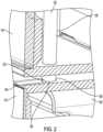
- FIG. 2 illustrates a perspective cutaway view of the two-step door latch mechanism in the lower, locked state.
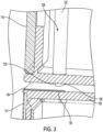
- FIG. 3 illustrates a perspective cutaway view of the two-step door latch mechanism in the raised, unlocked state.
- the locking pin 128 may define a generally tubular vertical shaft with a rounded lower end, the lower end further defining a flat face 132 for engaging a corresponding flat front of the pin receptacle 130.
- FIG. 4 a side view closeup of the pocket handle 118 and grip portion 124 of the latch 122 is illustrated.
- the grip portion 124 that is exposed to a user's hand within the recess of the pocket handle 118 is hidden inside the pocket handle 118.
- the grip portion 124 may define one or more indentations or grooves on its outer face to facilitate gripping by a user's fingers. These indentations may allow a user to better make contact with the latch 122.
- the latch 122 may slide downwards into the receptacle 130.
- the flat face 132 of the locking pin 128 may provide a surface to engage against the corresponding flat face of the receptacle 130. This action may accordingly resist against outward movement of the door 110, thereby preventing the door 110 from being opened when the latch 122 is in the lowered, locked position.
- a biasing element may be used to bias the locking post 126 downwardly when not raised by the user. In other examples, gravity may provide sufficient force to allow the latch 122 to default into the lowered, locked position.
- the control panel 112 portion of the housing 102 may further define a pin channel 134 extending across the top face of the control panel 112 from the receptacle 130 forward to the front of the housing 102.
- the pin channel 134 may define a recess contoured to correspond to the rounded lower end of the locking pin 128.
- the pin channel 134 urges the locking pin 128 upwards as the door 110 is moved inwards, the door 110 is not blocked from closing by the locking pin 128 coming into contact with the front of the control panel 112. Once the door 110 is fully closed, the locking pin 128 may reach and drop into the receptacle 130, thereby locking the door 110.
- a two-step process may be performed.
- the first step may include the user grabbing and raising the grip portion 124 of the latch 122 within the pocket handle 118. This may accordingly move the locking post 126 upwards, in turn lifting the locking pin 128 out of the receptacle 130 and into the raised, unlocked state.
- the second step may involve the user pulling the door 110.
- the grip portion 124 is located within the pocket handle 118, this two-step process may be operable using one hand.
- ease of actuation is maintained.
- child resistance is accordingly offered by the two distinct actions of the two-step mechanism.
Landscapes
- Engineering & Computer Science (AREA)
- Chemical & Material Sciences (AREA)
- Combustion & Propulsion (AREA)
- Mechanical Engineering (AREA)
- General Engineering & Computer Science (AREA)
- Physics & Mathematics (AREA)
- Electromagnetism (AREA)
- Electric Ovens (AREA)
Abstract
Description
- Aspects of the disclosure relate to appliances, and more particularly, to ovens that implement a two-step pocket handle mechanism for access to the oven cavity.
- Ovens are kitchen appliances that are used to cook food. A door may provide access to the oven cavity when opened. The door may seal the oven cavity for cooking when closed. A door opener mechanism may be provided to allow the user to open the door. In some examples, this mechanism includes a button that, when pressed into the face of the oven, pushes upon an internal mechanism to unlatch and push the door outward towards the user. In other examples, the mechanism includes a side pocket handle that may be used as a grip to pull the door open.
- In one or more embodiments, a two-step pocket handle latch mechanism for an oven is provided. A door is operable between open and closed positions with respect to an open front portion of an oven cavity defined by an oven housing. A pocket handle defines a recess extending into the side of the door opposite a pivotal connection of the door to the oven housing. A latch is controllable by a grip portion provided within the recess of the pocket handle, between a lower, locked position in which the latch prevents opening of the door, and a raised, unlocked position in which the latch allows the opening of the door.
- In one or more embodiments, an oven having a two-step door opening mechanism is provided. An oven housing defines an oven cavity having bottom, a top, side walls, and an open front portion. A door is operable between open and closed positions with respect to the open front portion of the oven cavity. The door includes a pocket handle defining a recess extending into the side of the door opposite a pivotal connection of the door to the oven housing, and a latch, controllable by a grip portion within the recess of the pocket handle, between a lower, locked position in which the latch prevents opening of the door, and a raised, unlocked position in which the latch allows the opening of the door.
- In one or more embodiments, a method for operation of a two-step pocket handle latch mechanism is provided. The method includes performing a first step to open a door to an oven, the first step including utilizing a latch, controllable by a grip portion within a recess of a pocket handle extending into the side of the door opposite a pivotal connection of the door to an oven housing, to move the latch between a lower, locked position in which the latch prevents opening of the door, and a raised, unlocked position in which the latch allows the opening of the door. The method further includes performing a second step to open the door to the oven, the second step including pulling the door open, using the pocket handle, while the latch is in the raised, unlocked position.
-
-
FIG. 1 illustrates a perspective view of an oven having a two-step door latch mechanism; -
FIG. 2 illustrates a perspective cutaway view of the two-step door latch mechanism in the locked state; -
FIG. 3 illustrates a perspective cutaway view of the two-step door latch mechanism in the unlocked state; and -
FIG. 4 illustrates a side view closeup of the pocket handle and latch of the two-step door latch mechanism. - As required, detailed embodiments of the present invention are disclosed herein; however, it is to be understood that the disclosed embodiments are merely exemplary of the invention that may be embodied in various and alternative forms. The figures are not necessarily to scale; some features may be exaggerated or minimized to show details of particular components. Therefore, specific structural and functional details disclosed herein are not to be interpreted as limiting, but merely as a representative basis for teaching one skilled in the art to variously employ the present invention.
- Some oven doors may be opened simply by pulling the door open. Such a single step door opener mechanism may be easy for a user to operate. However, such a door may lack child resistance.
- Aspects of the disclosure describe a two-step pocket handle latch mechanism for the operation of the oven door. A first step may include raising a latch within the pocket handle from a locked state into an unlocked state. A second step may include pulling the door open. In the locked state, the latch may fit into an opening in the oven housing below the door to prevent the door from opening. In the unlocked state, the latch may be raised to free the door. A latch grip may be hidden inside the pocket handle to avoid affecting the appearance of the oven. Additionally, as the latch grip is located within the pocket handle, the two-step pocket handle latch may be operable using one hand. Thus, ease of actuation is maintained. Moreover, child resistance is accordingly offered by requiring two distinct actions to be performed - raising the latch, and then pulling the door. Further aspects of the disclosure are discussed in detail herein.
-
FIG. 1 illustrates an example front view of anoven 100 having a two-step pockethandle latch mechanism 120. Theoven 100 may be of various types, such as a conventional oven, a microwave oven, or a combination microwave oven. While theoven 100 is shown as standalone, it should be noted that the two-step pockethandle latch mechanism 120 may be utilized in other types ofoven 100, such as a built-in oven, or a range having an oven portion. Moreover, the two-step pockethandle latch mechanism 120 may be incorporated into other types of appliances having locking doors, such as refrigerators or a front loading washers or dryers. - The
oven 100 includes ahousing 102 that defines anoven cavity 104. Theoven cavity 104 generally includes a bottom, a top, side walls, and anopen front portion 106. As shown, the cavity is relatively cylindrical in shape with a flat top and bottom, but in other examples, theoven cavity 104 may form a rectangular prism shape. In some examples, theoven cavity 104 may include aturntable 108 or other apparatus to allow for rotation of food items during a cooking cycle of theoven 100. - The
oven 100 also includes adoor 110 to theoven cavity 104. Thedoor 110 is generally operable between open and closed positions with respect to theopen front portion 106 of theoven cavity 104. In the open position, the user has access to theoven cavity 104 via theopen front portion 106, while in the closed position thedoor 110 seals theoven cavity 104 to allow for cooking to be performed. Thedoor 110 may operate as a side swing closure, pivotally coupled to theoven 100 on a vertical axis for rotational movement between the open and closed positions. Thus, thedoor 110 selectively provides access to theoven cavity 104. As illustrated inFIG. 1 , thedoor 110 is shown in a partially open position. - A
control panel 112 may also be provided on the front face of theoven 100, below thedoor 110. Thecontrol panel 112 area of thehousing 102 may extend forwards from theopen front portion 106 of theoven cavity 104 and may be the approximate thickness of thedoor 110, such that when thedoor 110 is closed, the front of thecontrol panel 112 may be flush with the front of thedoor 110. Thecontrol panel 112 may include controls that, when operated by a user, allow for the user to select one or more modes of operation for theoven 100. Thecontrol panel 112 may include a knob, button, or other control for controlling the operation of theoven 100. Thecontrol panel 112 may accordingly allow a user to select different levels of cooking. Thecontrol panel 112 may also include one or more lights, screens or other display elements to provide information to the user about the operation of theoven 100. - The
door 110 may include a latch mechanism to secure lock thedoor 110 in the closed position. For instance, thedoor 110 may define afastener 114 that fits into aslot 116 in the front face of thehousing 102 when thedoor 110 is rotated into the closed position. When the door is closed, thefastener 114 may snaps over a protrusion, hook, or other mechanism (not shown) to hold thedoor 110 in the closed position. - To facilitate door operation, the
door 110 may define apocket handle 118 on the opposite side of thedoor 110 from the hinged connection to thehousing 102. As shown, the hinge is on the left side of thedoor 110 and thepocket handle 118 is on the right side of thedoor 110, but this may be reversed in other designs. The pocket handle 118 may define a recess extending vertically into the side of thedoor 110. Using thepocket handle 118, a user can insert their fingers into the recess and pull against the front of the recess, overcoming the hold of thefastener 114 and rotating the door to provide access to theoven cavity 104. The user may close the door by pushing thedoor 110 inwards, thereby causing the door to rotate back into the closed position. - Such an
oven door 110 may be easily opened with only one step, i.e., pulling thedoor 110 open using thepocket handle 118. However, such adoor 110 may also be easily opened by a child. This may be undesirable if the child should not have access to hot food items theoven cavity 104. As explained in detail herein, a two-step pockethandle latch mechanism 120 may be used to allow for securing of theoven door 110. A first step may include raising alatch 122 within the pocket handle 118 from a locked state into an unlocked state. A second step may include pulling thedoor 110 open using the pocket handle 118 once thelatch 122 is raised. - The
latch 122 may define agrip portion 124, illustrated herein at an upper end of thelatch 122. Thegrip portion 124 may facilitate operation of thelatch 122 by giving the user a convenient handle to grip onto and raise thelatch 122 as desired. Thelatch 122 may further define a lockingpost 126 provided within the interior of thedoor 110, such that the lockingpost 126 is nested between front and back panels of thedoor 110. The lockingpost 126 may further define alocking pin 128 protruding downward from a lower end of the lockingpost 126. The lockingpost 126 may be movable within and relative to thedoor 110, such that the lockingpost 126 is vertically slidable within and relative to thedoor 110 between a lower, locked position and a raised, unlocked position. - The
locking pin 128 may be configured to engage with areceptacle 130 defined by thecontrol panel 112 portion of thehousing 102 below thedoor 110. Thereceptacle 130 may be sized and located in a position to allow thelocking pin 128 to pass downward into thecontrol panel 112 area when thedoor 110 is in the closed position. -
FIG. 2 illustrates a perspective cutaway view of the two-step door latch mechanism in the lower, locked state.FIG. 3 illustrates a perspective cutaway view of the two-step door latch mechanism in the raised, unlocked state. Referring collectively toFIGS. 2-3 , the lockingpin 128 may define a generally tubular vertical shaft with a rounded lower end, the lower end further defining aflat face 132 for engaging a corresponding flat front of thepin receptacle 130. - Referring more specifically to
FIG. 4 , a side view closeup of thepocket handle 118 andgrip portion 124 of thelatch 122 is illustrated. As shown, thegrip portion 124 that is exposed to a user's hand within the recess of thepocket handle 118 is hidden inside thepocket handle 118. Advantageously, this may avoid affecting the outer look or aesthetics of thedoor 110. In an example, thegrip portion 124 may define one or more indentations or grooves on its outer face to facilitate gripping by a user's fingers. These indentations may allow a user to better make contact with thelatch 122. - To enter the locked state, the
latch 122 may slide downwards into thereceptacle 130. When thedoor 110 is closed and thelocking pin 128 is lowered, theflat face 132 of thelocking pin 128 may provide a surface to engage against the corresponding flat face of thereceptacle 130. This action may accordingly resist against outward movement of thedoor 110, thereby preventing thedoor 110 from being opened when thelatch 122 is in the lowered, locked position. Although not shown, a biasing element may be used to bias the lockingpost 126 downwardly when not raised by the user. In other examples, gravity may provide sufficient force to allow thelatch 122 to default into the lowered, locked position. - The
control panel 112 portion of thehousing 102 may further define apin channel 134 extending across the top face of thecontrol panel 112 from thereceptacle 130 forward to the front of thehousing 102. Thepin channel 134 may define a recess contoured to correspond to the rounded lower end of thelocking pin 128. When thedoor 110 of theoven 100 pushed to close thedoor 110, the lockingpin 128 may be in the lowered position. As the lower end of thelocking pin 128 is forced against thepin channel 134, thepin channel 134 may serve to guide thelocking pin 128 upwards. As thepin channel 134 urges thelocking pin 128 upwards as thedoor 110 is moved inwards, thedoor 110 is not blocked from closing by the lockingpin 128 coming into contact with the front of thecontrol panel 112. Once thedoor 110 is fully closed, the lockingpin 128 may reach and drop into thereceptacle 130, thereby locking thedoor 110. - To open the
door 110, a two-step process may be performed. As shown by operation (A), the first step may include the user grabbing and raising thegrip portion 124 of thelatch 122 within thepocket handle 118. This may accordingly move the lockingpost 126 upwards, in turn lifting thelocking pin 128 out of thereceptacle 130 and into the raised, unlocked state. As shown by operation (B), while the first step is being performed, the second step may involve the user pulling thedoor 110. As thegrip portion 124 is located within thepocket handle 118, this two-step process may be operable using one hand. Thus, ease of actuation is maintained. Moreover, child resistance is accordingly offered by the two distinct actions of the two-step mechanism. - Accordingly, it is to be understood that the above description is intended to be illustrative and not restrictive. Many embodiments and applications other than the examples provided would be apparent upon reading the above description. The scope should be determined, not with reference to the above description, but should instead be determined with reference to the appended claims, along with the full scope of equivalents to which such claims are entitled. It is anticipated and intended that future developments will occur in the technologies discussed herein, and that the disclosed systems and methods will be incorporated into such future embodiments. In sum, it should be understood that the application is capable of modification and variation.
- All terms used in the claims are intended to be given their broadest reasonable constructions and their ordinary meanings as understood by those knowledgeable in the technologies described herein unless an explicit indication to the contrary is made herein. In particular, use of the singular articles such as "a," "the," "said," etc. should be read to recite one or more of the indicated elements unless a claim recites an explicit limitation to the contrary.
- The abstract of the disclosure is provided to allow the reader to quickly ascertain the nature of the technical disclosure. It is submitted with the understanding that it will not be used to interpret or limit the scope or meaning of the claims. In addition, in the foregoing Detailed Description, it can be seen that various features are grouped together in various embodiments for the purpose of streamlining the disclosure. This method of disclosure is not to be interpreted as reflecting an intention that the claimed embodiments require more features than are expressly recited in each claim. Rather, as the following claims reflect, inventive subject matter lies in less than all features of a single disclosed embodiment. Thus, the following claims are hereby incorporated into the Detailed Description, with each claim standing on its own as a separately claimed subject matter.
- While exemplary embodiments are described above, it is not intended that these embodiments describe all possible forms of the invention. Rather, the words used in the specification are words of description rather than limitation, and it is understood that various changes may be made without departing from the spirit and scope of the invention. Additionally, the features of various implementing embodiments may be combined to form further embodiments of the invention.
Claims (15)
- An oven (100), in particular a microwave oven, comprising:a housing (102) defining a cavity (104);a door (110) coupled to the housing (102) by means of a pivotal connection of the door (110) to the housing (102) at a first side of the door (110), the door (110) being operable between an open position and a closed position with respect to an open front portion (106) of the cavity (104); anda pocket handle (118) defining a recess extending into a second side of the door (110) opposite to the first side;characterised by further comprising:a grip portion (124) accommodated within the recess of the pocket handle (118), anda latch (112) controllable by means of the grip portion (124), the latch (112) being operable between a locked position in which the latch (112) prevents opening of the door (110), and an unlocked position in which the latch (112) allows the opening of the door (110).
- The oven (100) of claim 1, wherein the grip portion (124) and the latch (112) are configured to realise in combination a two-step opening mechanism (120) of the door (110), wherein:in a first step the latch (112) is moved, by means of the grip portion (124), from the locked position to the unlocked position andin a second step the door (110) is pulled using the pocket handle (118), while the latch (112) is in the unlocked position.
- The oven (100) of claim 1 or claim 2, wherein the latch (112), when in the unlocked position, is raised compared to when in the locked position.
- The oven (100) of any one of the previous claims, the latch (112) further comprising:a locking post (126) provided within the interior of the door (110), the locking post (126) being in particular nested between a front panel and a back panel of the door (110), anda locking pin (128) protruding downwardly from a lower end of the locking post (126), the locking post (126) being movable within and relative to the door (110), such that the locking post (126) is vertically slidable within and relative to the door (110) between the locked position of the latch (112) and the unlocked position of the latch (112).
- The oven (100) of claim 4, wherein the housing (102) defines a pin receptacle (130) sized and located to allow the locking pin (128) to pass downward into the housing (102) when the door (110) is in the closed position.
- The oven (100) of claim 5, wherein an end, preferably a lower end, of the locking pin (128) defines a front face, preferably a flat front face, configured for engaging a corresponding front, preferably a corresponding flat front, of the pin receptacle (130) when the latch (112) is in the locked position, optionally wherein the engagement of a surface of the front face of the locking pin (128) against the pin receptacle (130) is such to resist outward movement of the door (110).
- The oven (100) of claim 5 or claim 6, further comprising a pin channel (134) configured to guide the locking pin (128), wherein the pin channel (134) is contoured to correspond to a rounded end of the locking pin (128).
- The oven (100) of any one of the previous claims, wherein the grip portion (124) defines one or more indentations or grooves on an outer face, the indentations or grooves being sized to facilitate gripping by fingers of a user.
- The oven (100) of any one of the previous claims, further comprising a biasing element configured to bias the latch (112) into the locked position.
- The oven (100) of any one of the previous claims, further comprising a control panel (112), wherein the control panel (112) is arranged at an area, in particular at a front area, of the housing (102) below the door (110),optionally wherein the area of the housing (102) with the control panel (112) extends forwards from the open front portion (106) of the cavity (104) and/oroptionally wherein the front of the area of the housing (102) with the control panel (112) is flush with the front of the door (110) when the door (110) is in the closed position.
- The oven (100) of claim 10, wherein the area of the housing (102) with the control panel (112) defines the pin receptacle (130),
optionally wherein the pin channel (134) extends across the top face of the area of the housing (102) with the control panel (112) from the pin receptacle (130) forward to the front of the housing (102). - The oven (100) of any one of the previous claims, wherein the grip portion (124) and/or the latch (112) are hidden inside the pocket handle (118) to avoid affecting the outer look of the oven (100).
- A method for opening a door (110) of an oven (100), in particular a microwave oven, comprising the steps of:moving a latch (112) between a locked position in which the latch (112) prevents opening of the door (110) and an unlocked position in which the latch (112) allows the opening of the door (110), the latch (112) being controllable by means of a grip portion (124) within a recess of a pocket handle (118) extending into the side of the door (110) opposite a pivotal connection of the door (110) to a housing (102); andpulling the door (110) open, using the pocket handle (118).
- The method of claim 13, wherein the step of pulling the door (110) open is performed while the latch (112) is in the unlocked position.
- The method of claim 13 or claim 14, wherein the step of moving the latch (112) and the step of pulling the door (110) open are performed using a single hand.
Applications Claiming Priority (1)
| Application Number | Priority Date | Filing Date | Title |
|---|---|---|---|
| US18/050,109 US12516823B2 (en) | 2022-10-27 | 2022-10-27 | Two-step door opening combination |
Publications (1)
| Publication Number | Publication Date |
|---|---|
| EP4361502A1 true EP4361502A1 (en) | 2024-05-01 |
Family
ID=88598640
Family Applications (1)
| Application Number | Title | Priority Date | Filing Date |
|---|---|---|---|
| EP23206484.0A Pending EP4361502A1 (en) | 2022-10-27 | 2023-10-27 | Two-step door opening combination |
Country Status (2)
| Country | Link |
|---|---|
| US (1) | US12516823B2 (en) |
| EP (1) | EP4361502A1 (en) |
Citations (6)
| Publication number | Priority date | Publication date | Assignee | Title |
|---|---|---|---|---|
| DE1959910U (en) * | 1965-04-15 | 1967-05-11 | Constructa Werke G M B H | SAFETY INTERLOCK FOR LOADING DOORS OF ELECTRIC HOUSEHOLD APPLIANCES. |
| FR2294675A1 (en) * | 1974-12-19 | 1976-07-16 | Electrolux Ab | DOOR LOCKING DEVICE FOR DISHWASHING MACHINE |
| JPH09178196A (en) * | 1995-12-28 | 1997-07-11 | Rinnai Corp | Front door of heating cooker |
| WO2011039362A1 (en) * | 2009-10-02 | 2011-04-07 | BSH Bosch und Siemens Hausgeräte GmbH | Door device for a household appliance, household appliance comprising such a door device and method for actuating a door device for a household appliance |
| JP2012042119A (en) * | 2010-08-18 | 2012-03-01 | Mitsubishi Electric Corp | Heating cooker |
| DE202014010390U1 (en) * | 2014-06-04 | 2015-06-30 | Meiko Maschinenbau Gmbh & Co. Kg | Device for closing a treatment room of a dishwasher |
Family Cites Families (9)
| Publication number | Priority date | Publication date | Assignee | Title |
|---|---|---|---|---|
| JPS5256523Y2 (en) | 1974-02-26 | 1977-12-21 | ||
| US4457545A (en) * | 1982-05-03 | 1984-07-03 | General Electric Company | Door latch assembly |
| WO2011039364A1 (en) | 2009-10-02 | 2011-04-07 | BSH Bosch und Siemens Hausgeräte GmbH | Door-opening device for a domestic appliance, and domestic appliance with such a door-opening device |
| WO2018224159A1 (en) * | 2017-06-09 | 2018-12-13 | Arcelik Anonim Sirketi | Oven door child lock having a handle controlled locking mechanism |
| CN111397267A (en) | 2018-12-28 | 2020-07-10 | 青岛海尔智能技术研发有限公司 | Child lock refrigerator |
| CN110856299B (en) * | 2019-09-26 | 2022-03-11 | 广东格兰仕集团有限公司 | Cooking appliance and door body thereof |
| CN111227632B (en) * | 2020-01-22 | 2021-08-31 | 广东格兰仕集团有限公司 | Electric cooking appliance |
| US11821633B2 (en) | 2020-07-24 | 2023-11-21 | Haier Us Appliance Solutions, Inc. | Over-the-range microwave including airflow regulating features |
| WO2023173513A1 (en) * | 2022-03-18 | 2023-09-21 | 广东美的厨房电器制造有限公司 | Door structure and cooking device |
-
2022
- 2022-10-27 US US18/050,109 patent/US12516823B2/en active Active
-
2023
- 2023-10-27 EP EP23206484.0A patent/EP4361502A1/en active Pending
Patent Citations (6)
| Publication number | Priority date | Publication date | Assignee | Title |
|---|---|---|---|---|
| DE1959910U (en) * | 1965-04-15 | 1967-05-11 | Constructa Werke G M B H | SAFETY INTERLOCK FOR LOADING DOORS OF ELECTRIC HOUSEHOLD APPLIANCES. |
| FR2294675A1 (en) * | 1974-12-19 | 1976-07-16 | Electrolux Ab | DOOR LOCKING DEVICE FOR DISHWASHING MACHINE |
| JPH09178196A (en) * | 1995-12-28 | 1997-07-11 | Rinnai Corp | Front door of heating cooker |
| WO2011039362A1 (en) * | 2009-10-02 | 2011-04-07 | BSH Bosch und Siemens Hausgeräte GmbH | Door device for a household appliance, household appliance comprising such a door device and method for actuating a door device for a household appliance |
| JP2012042119A (en) * | 2010-08-18 | 2012-03-01 | Mitsubishi Electric Corp | Heating cooker |
| DE202014010390U1 (en) * | 2014-06-04 | 2015-06-30 | Meiko Maschinenbau Gmbh & Co. Kg | Device for closing a treatment room of a dishwasher |
Also Published As
| Publication number | Publication date |
|---|---|
| US20240142111A1 (en) | 2024-05-02 |
| US12516823B2 (en) | 2026-01-06 |
Similar Documents
| Publication | Publication Date | Title |
|---|---|---|
| KR101762971B1 (en) | Sliding and tilting door assembly | |
| US20100206289A1 (en) | Door locking mechanism for an oven having french-style doors | |
| CN101501428B (en) | Refrigerator and control method thereof | |
| KR102464262B1 (en) | Household electrical appliances having with door key linked to rotation movement of door | |
| US11773619B2 (en) | Door lock system for an appliance | |
| US20240032770A1 (en) | Household appliance, in particular aquiferous household appliance | |
| EP4023944B1 (en) | Appliance door hinge assembly | |
| US12516823B2 (en) | Two-step door opening combination | |
| CN112041524B (en) | Latch module and cooking equipment using the latch module | |
| KR102003113B1 (en) | Handle assembly for window having function for confirming the open and close state | |
| KR20180090471A (en) | Handle assembly for window having a safety lock structure | |
| CN116624028A (en) | Door assemblies for cooking appliances and cooking appliances | |
| US20220042357A1 (en) | Locking device for window or door and method of operating thereof | |
| KR20110039994A (en) | Locking part assembly of window lock | |
| US20230375186A1 (en) | Two-step door opening combination | |
| US12426134B2 (en) | Interlock system with hinge connection for appliance door | |
| JP2007032122A (en) | Fittings | |
| JP3146820B2 (en) | Vending machine door lock mechanism | |
| EP1998117B1 (en) | Food cooking oven with a door closing device | |
| AU2023388164A1 (en) | An appliance | |
| CN117027561B (en) | Door assembly of cooking utensil and cooking utensil | |
| CN223286952U (en) | cooking utensils | |
| CN220522283U (en) | Cooking appliance door assemblies and cooking appliances | |
| CN220522370U (en) | Door assembly of cooking utensil and cooking utensil | |
| CN220256325U (en) | Double door structure of electric oven |
Legal Events
| Date | Code | Title | Description |
|---|---|---|---|
| PUAI | Public reference made under article 153(3) epc to a published international application that has entered the european phase |
Free format text: ORIGINAL CODE: 0009012 |
|
| STAA | Information on the status of an ep patent application or granted ep patent |
Free format text: STATUS: THE APPLICATION HAS BEEN PUBLISHED |
|
| AK | Designated contracting states |
Kind code of ref document: A1 Designated state(s): AL AT BE BG CH CY CZ DE DK EE ES FI FR GB GR HR HU IE IS IT LI LT LU LV MC ME MK MT NL NO PL PT RO RS SE SI SK SM TR |
|
| STAA | Information on the status of an ep patent application or granted ep patent |
Free format text: STATUS: REQUEST FOR EXAMINATION WAS MADE |
|
| RAP1 | Party data changed (applicant data changed or rights of an application transferred) |
Owner name: BEKO EUROPE MANAGEMENT S.R.L. |
|
| 17P | Request for examination filed |
Effective date: 20241030 |
|
| P01 | Opt-out of the competence of the unified patent court (upc) registered |
Free format text: CASE NUMBER: APP_59209/2024 Effective date: 20241030 |
|
| RBV | Designated contracting states (corrected) |
Designated state(s): AL AT BE BG CH CY CZ DE DK EE ES FI FR GB GR HR HU IE IS IT LI LT LU LV MC ME MK MT NL NO PL PT RO RS SE SI SK SM TR |
|
| STAA | Information on the status of an ep patent application or granted ep patent |
Free format text: STATUS: EXAMINATION IS IN PROGRESS |
|
| 17Q | First examination report despatched |
Effective date: 20250722 |