EP4361498A1 - Lamp for vehicle - Google Patents
Lamp for vehicle Download PDFInfo
- Publication number
- EP4361498A1 EP4361498A1 EP22213068.4A EP22213068A EP4361498A1 EP 4361498 A1 EP4361498 A1 EP 4361498A1 EP 22213068 A EP22213068 A EP 22213068A EP 4361498 A1 EP4361498 A1 EP 4361498A1
- Authority
- EP
- European Patent Office
- Prior art keywords
- lamp
- reflective surface
- light
- present disclosure
- light source
- Prior art date
- Legal status (The legal status is an assumption and is not a legal conclusion. Google has not performed a legal analysis and makes no representation as to the accuracy of the status listed.)
- Granted
Links
Images








Classifications
-
- F—MECHANICAL ENGINEERING; LIGHTING; HEATING; WEAPONS; BLASTING
- F21—LIGHTING
- F21S—NON-PORTABLE LIGHTING DEVICES; SYSTEMS THEREOF; VEHICLE LIGHTING DEVICES SPECIALLY ADAPTED FOR VEHICLE EXTERIORS
- F21S41/00—Illuminating devices specially adapted for vehicle exteriors, e.g. headlamps
- F21S41/30—Illuminating devices specially adapted for vehicle exteriors, e.g. headlamps characterised by reflectors
- F21S41/32—Optical layout thereof
- F21S41/33—Multi-surface reflectors, e.g. reflectors with facets or reflectors with portions of different curvature
-
- F—MECHANICAL ENGINEERING; LIGHTING; HEATING; WEAPONS; BLASTING
- F21—LIGHTING
- F21S—NON-PORTABLE LIGHTING DEVICES; SYSTEMS THEREOF; VEHICLE LIGHTING DEVICES SPECIALLY ADAPTED FOR VEHICLE EXTERIORS
- F21S41/00—Illuminating devices specially adapted for vehicle exteriors, e.g. headlamps
- F21S41/30—Illuminating devices specially adapted for vehicle exteriors, e.g. headlamps characterised by reflectors
- F21S41/37—Illuminating devices specially adapted for vehicle exteriors, e.g. headlamps characterised by reflectors characterised by their material, surface treatment or coatings
-
- F—MECHANICAL ENGINEERING; LIGHTING; HEATING; WEAPONS; BLASTING
- F21—LIGHTING
- F21S—NON-PORTABLE LIGHTING DEVICES; SYSTEMS THEREOF; VEHICLE LIGHTING DEVICES SPECIALLY ADAPTED FOR VEHICLE EXTERIORS
- F21S41/00—Illuminating devices specially adapted for vehicle exteriors, e.g. headlamps
- F21S41/10—Illuminating devices specially adapted for vehicle exteriors, e.g. headlamps characterised by the light source
- F21S41/14—Illuminating devices specially adapted for vehicle exteriors, e.g. headlamps characterised by the light source characterised by the type of light source
- F21S41/141—Light emitting diodes [LED]
- F21S41/147—Light emitting diodes [LED] the main emission direction of the LED being angled to the optical axis of the illuminating device
- F21S41/148—Light emitting diodes [LED] the main emission direction of the LED being angled to the optical axis of the illuminating device the main emission direction of the LED being perpendicular to the optical axis
-
- F—MECHANICAL ENGINEERING; LIGHTING; HEATING; WEAPONS; BLASTING
- F21—LIGHTING
- F21S—NON-PORTABLE LIGHTING DEVICES; SYSTEMS THEREOF; VEHICLE LIGHTING DEVICES SPECIALLY ADAPTED FOR VEHICLE EXTERIORS
- F21S41/00—Illuminating devices specially adapted for vehicle exteriors, e.g. headlamps
- F21S41/10—Illuminating devices specially adapted for vehicle exteriors, e.g. headlamps characterised by the light source
- F21S41/14—Illuminating devices specially adapted for vehicle exteriors, e.g. headlamps characterised by the light source characterised by the type of light source
- F21S41/141—Light emitting diodes [LED]
- F21S41/151—Light emitting diodes [LED] arranged in one or more lines
-
- F—MECHANICAL ENGINEERING; LIGHTING; HEATING; WEAPONS; BLASTING
- F21—LIGHTING
- F21S—NON-PORTABLE LIGHTING DEVICES; SYSTEMS THEREOF; VEHICLE LIGHTING DEVICES SPECIALLY ADAPTED FOR VEHICLE EXTERIORS
- F21S41/00—Illuminating devices specially adapted for vehicle exteriors, e.g. headlamps
- F21S41/10—Illuminating devices specially adapted for vehicle exteriors, e.g. headlamps characterised by the light source
- F21S41/14—Illuminating devices specially adapted for vehicle exteriors, e.g. headlamps characterised by the light source characterised by the type of light source
- F21S41/176—Light sources where the light is generated by photoluminescent material spaced from a primary light generating element
-
- F—MECHANICAL ENGINEERING; LIGHTING; HEATING; WEAPONS; BLASTING
- F21—LIGHTING
- F21S—NON-PORTABLE LIGHTING DEVICES; SYSTEMS THEREOF; VEHICLE LIGHTING DEVICES SPECIALLY ADAPTED FOR VEHICLE EXTERIORS
- F21S41/00—Illuminating devices specially adapted for vehicle exteriors, e.g. headlamps
- F21S41/20—Illuminating devices specially adapted for vehicle exteriors, e.g. headlamps characterised by refractors, transparent cover plates, light guides or filters
- F21S41/25—Projection lenses
-
- F—MECHANICAL ENGINEERING; LIGHTING; HEATING; WEAPONS; BLASTING
- F21—LIGHTING
- F21S—NON-PORTABLE LIGHTING DEVICES; SYSTEMS THEREOF; VEHICLE LIGHTING DEVICES SPECIALLY ADAPTED FOR VEHICLE EXTERIORS
- F21S41/00—Illuminating devices specially adapted for vehicle exteriors, e.g. headlamps
- F21S41/20—Illuminating devices specially adapted for vehicle exteriors, e.g. headlamps characterised by refractors, transparent cover plates, light guides or filters
- F21S41/285—Refractors, transparent cover plates, light guides or filters not provided in groups F21S41/24 - F21S41/2805
-
- F—MECHANICAL ENGINEERING; LIGHTING; HEATING; WEAPONS; BLASTING
- F21—LIGHTING
- F21S—NON-PORTABLE LIGHTING DEVICES; SYSTEMS THEREOF; VEHICLE LIGHTING DEVICES SPECIALLY ADAPTED FOR VEHICLE EXTERIORS
- F21S41/00—Illuminating devices specially adapted for vehicle exteriors, e.g. headlamps
- F21S41/30—Illuminating devices specially adapted for vehicle exteriors, e.g. headlamps characterised by reflectors
- F21S41/32—Optical layout thereof
- F21S41/321—Optical layout thereof the reflector being a surface of revolution or a planar surface, e.g. truncated
-
- F—MECHANICAL ENGINEERING; LIGHTING; HEATING; WEAPONS; BLASTING
- F21—LIGHTING
- F21S—NON-PORTABLE LIGHTING DEVICES; SYSTEMS THEREOF; VEHICLE LIGHTING DEVICES SPECIALLY ADAPTED FOR VEHICLE EXTERIORS
- F21S41/00—Illuminating devices specially adapted for vehicle exteriors, e.g. headlamps
- F21S41/30—Illuminating devices specially adapted for vehicle exteriors, e.g. headlamps characterised by reflectors
- F21S41/32—Optical layout thereof
- F21S41/323—Optical layout thereof the reflector having two perpendicular cross sections having regular geometrical curves of a distinct nature
-
- F—MECHANICAL ENGINEERING; LIGHTING; HEATING; WEAPONS; BLASTING
- F21—LIGHTING
- F21S—NON-PORTABLE LIGHTING DEVICES; SYSTEMS THEREOF; VEHICLE LIGHTING DEVICES SPECIALLY ADAPTED FOR VEHICLE EXTERIORS
- F21S41/00—Illuminating devices specially adapted for vehicle exteriors, e.g. headlamps
- F21S41/30—Illuminating devices specially adapted for vehicle exteriors, e.g. headlamps characterised by reflectors
- F21S41/32—Optical layout thereof
- F21S41/33—Multi-surface reflectors, e.g. reflectors with facets or reflectors with portions of different curvature
- F21S41/334—Multi-surface reflectors, e.g. reflectors with facets or reflectors with portions of different curvature the reflector consisting of patch like sectors
- F21S41/336—Multi-surface reflectors, e.g. reflectors with facets or reflectors with portions of different curvature the reflector consisting of patch like sectors with discontinuity at the junction between adjacent areas
-
- F—MECHANICAL ENGINEERING; LIGHTING; HEATING; WEAPONS; BLASTING
- F21—LIGHTING
- F21S—NON-PORTABLE LIGHTING DEVICES; SYSTEMS THEREOF; VEHICLE LIGHTING DEVICES SPECIALLY ADAPTED FOR VEHICLE EXTERIORS
- F21S41/00—Illuminating devices specially adapted for vehicle exteriors, e.g. headlamps
- F21S41/30—Illuminating devices specially adapted for vehicle exteriors, e.g. headlamps characterised by reflectors
- F21S41/32—Optical layout thereof
- F21S41/33—Multi-surface reflectors, e.g. reflectors with facets or reflectors with portions of different curvature
- F21S41/337—Multi-surface reflectors, e.g. reflectors with facets or reflectors with portions of different curvature the reflector having a structured surface, e.g. with facets or corrugations
-
- F—MECHANICAL ENGINEERING; LIGHTING; HEATING; WEAPONS; BLASTING
- F21—LIGHTING
- F21S—NON-PORTABLE LIGHTING DEVICES; SYSTEMS THEREOF; VEHICLE LIGHTING DEVICES SPECIALLY ADAPTED FOR VEHICLE EXTERIORS
- F21S43/00—Signalling devices specially adapted for vehicle exteriors, e.g. brake lamps, direction indicator lights or reversing lights
- F21S43/10—Signalling devices specially adapted for vehicle exteriors, e.g. brake lamps, direction indicator lights or reversing lights characterised by the light source
- F21S43/13—Signalling devices specially adapted for vehicle exteriors, e.g. brake lamps, direction indicator lights or reversing lights characterised by the light source characterised by the type of light source
- F21S43/14—Light emitting diodes [LED]
-
- F—MECHANICAL ENGINEERING; LIGHTING; HEATING; WEAPONS; BLASTING
- F21—LIGHTING
- F21S—NON-PORTABLE LIGHTING DEVICES; SYSTEMS THEREOF; VEHICLE LIGHTING DEVICES SPECIALLY ADAPTED FOR VEHICLE EXTERIORS
- F21S43/00—Signalling devices specially adapted for vehicle exteriors, e.g. brake lamps, direction indicator lights or reversing lights
- F21S43/10—Signalling devices specially adapted for vehicle exteriors, e.g. brake lamps, direction indicator lights or reversing lights characterised by the light source
- F21S43/13—Signalling devices specially adapted for vehicle exteriors, e.g. brake lamps, direction indicator lights or reversing lights characterised by the light source characterised by the type of light source
- F21S43/15—Strips of light sources
-
- F—MECHANICAL ENGINEERING; LIGHTING; HEATING; WEAPONS; BLASTING
- F21—LIGHTING
- F21S—NON-PORTABLE LIGHTING DEVICES; SYSTEMS THEREOF; VEHICLE LIGHTING DEVICES SPECIALLY ADAPTED FOR VEHICLE EXTERIORS
- F21S43/00—Signalling devices specially adapted for vehicle exteriors, e.g. brake lamps, direction indicator lights or reversing lights
- F21S43/10—Signalling devices specially adapted for vehicle exteriors, e.g. brake lamps, direction indicator lights or reversing lights characterised by the light source
- F21S43/13—Signalling devices specially adapted for vehicle exteriors, e.g. brake lamps, direction indicator lights or reversing lights characterised by the light source characterised by the type of light source
- F21S43/16—Light sources where the light is generated by photoluminescent material spaced from a primary light generating element
-
- F—MECHANICAL ENGINEERING; LIGHTING; HEATING; WEAPONS; BLASTING
- F21—LIGHTING
- F21S—NON-PORTABLE LIGHTING DEVICES; SYSTEMS THEREOF; VEHICLE LIGHTING DEVICES SPECIALLY ADAPTED FOR VEHICLE EXTERIORS
- F21S43/00—Signalling devices specially adapted for vehicle exteriors, e.g. brake lamps, direction indicator lights or reversing lights
- F21S43/20—Signalling devices specially adapted for vehicle exteriors, e.g. brake lamps, direction indicator lights or reversing lights characterised by refractors, transparent cover plates, light guides or filters
-
- F—MECHANICAL ENGINEERING; LIGHTING; HEATING; WEAPONS; BLASTING
- F21—LIGHTING
- F21S—NON-PORTABLE LIGHTING DEVICES; SYSTEMS THEREOF; VEHICLE LIGHTING DEVICES SPECIALLY ADAPTED FOR VEHICLE EXTERIORS
- F21S43/00—Signalling devices specially adapted for vehicle exteriors, e.g. brake lamps, direction indicator lights or reversing lights
- F21S43/20—Signalling devices specially adapted for vehicle exteriors, e.g. brake lamps, direction indicator lights or reversing lights characterised by refractors, transparent cover plates, light guides or filters
- F21S43/26—Refractors, transparent cover plates, light guides or filters not provided in groups F21S43/235 - F21S43/255
-
- F—MECHANICAL ENGINEERING; LIGHTING; HEATING; WEAPONS; BLASTING
- F21—LIGHTING
- F21S—NON-PORTABLE LIGHTING DEVICES; SYSTEMS THEREOF; VEHICLE LIGHTING DEVICES SPECIALLY ADAPTED FOR VEHICLE EXTERIORS
- F21S43/00—Signalling devices specially adapted for vehicle exteriors, e.g. brake lamps, direction indicator lights or reversing lights
- F21S43/20—Signalling devices specially adapted for vehicle exteriors, e.g. brake lamps, direction indicator lights or reversing lights characterised by refractors, transparent cover plates, light guides or filters
- F21S43/281—Materials thereof; Structures thereof; Properties thereof; Coatings thereof
- F21S43/28135—Structures encapsulating the light source
-
- F—MECHANICAL ENGINEERING; LIGHTING; HEATING; WEAPONS; BLASTING
- F21—LIGHTING
- F21S—NON-PORTABLE LIGHTING DEVICES; SYSTEMS THEREOF; VEHICLE LIGHTING DEVICES SPECIALLY ADAPTED FOR VEHICLE EXTERIORS
- F21S43/00—Signalling devices specially adapted for vehicle exteriors, e.g. brake lamps, direction indicator lights or reversing lights
- F21S43/30—Signalling devices specially adapted for vehicle exteriors, e.g. brake lamps, direction indicator lights or reversing lights characterised by reflectors
- F21S43/31—Optical layout thereof
-
- F—MECHANICAL ENGINEERING; LIGHTING; HEATING; WEAPONS; BLASTING
- F21—LIGHTING
- F21S—NON-PORTABLE LIGHTING DEVICES; SYSTEMS THEREOF; VEHICLE LIGHTING DEVICES SPECIALLY ADAPTED FOR VEHICLE EXTERIORS
- F21S43/00—Signalling devices specially adapted for vehicle exteriors, e.g. brake lamps, direction indicator lights or reversing lights
- F21S43/30—Signalling devices specially adapted for vehicle exteriors, e.g. brake lamps, direction indicator lights or reversing lights characterised by reflectors
- F21S43/33—Signalling devices specially adapted for vehicle exteriors, e.g. brake lamps, direction indicator lights or reversing lights characterised by reflectors characterised by their material, surface treatment or coatings
-
- F—MECHANICAL ENGINEERING; LIGHTING; HEATING; WEAPONS; BLASTING
- F21—LIGHTING
- F21S—NON-PORTABLE LIGHTING DEVICES; SYSTEMS THEREOF; VEHICLE LIGHTING DEVICES SPECIALLY ADAPTED FOR VEHICLE EXTERIORS
- F21S43/00—Signalling devices specially adapted for vehicle exteriors, e.g. brake lamps, direction indicator lights or reversing lights
- F21S43/40—Signalling devices specially adapted for vehicle exteriors, e.g. brake lamps, direction indicator lights or reversing lights characterised by the combination of reflectors and refractors
-
- F—MECHANICAL ENGINEERING; LIGHTING; HEATING; WEAPONS; BLASTING
- F21—LIGHTING
- F21V—FUNCTIONAL FEATURES OR DETAILS OF LIGHTING DEVICES OR SYSTEMS THEREOF; STRUCTURAL COMBINATIONS OF LIGHTING DEVICES WITH OTHER ARTICLES, NOT OTHERWISE PROVIDED FOR
- F21V13/00—Producing particular characteristics or distribution of the light emitted by means of a combination of elements specified in two or more of main groups F21V1/00 - F21V11/00
- F21V13/02—Combinations of only two kinds of elements
- F21V13/04—Combinations of only two kinds of elements the elements being reflectors and refractors
-
- F—MECHANICAL ENGINEERING; LIGHTING; HEATING; WEAPONS; BLASTING
- F21—LIGHTING
- F21V—FUNCTIONAL FEATURES OR DETAILS OF LIGHTING DEVICES OR SYSTEMS THEREOF; STRUCTURAL COMBINATIONS OF LIGHTING DEVICES WITH OTHER ARTICLES, NOT OTHERWISE PROVIDED FOR
- F21V3/00—Globes; Bowls; Cover glasses
- F21V3/04—Globes; Bowls; Cover glasses characterised by materials, surface treatments or coatings
- F21V3/10—Globes; Bowls; Cover glasses characterised by materials, surface treatments or coatings characterised by coatings
- F21V3/12—Globes; Bowls; Cover glasses characterised by materials, surface treatments or coatings characterised by coatings the coatings comprising photoluminescent substances
-
- F—MECHANICAL ENGINEERING; LIGHTING; HEATING; WEAPONS; BLASTING
- F21—LIGHTING
- F21V—FUNCTIONAL FEATURES OR DETAILS OF LIGHTING DEVICES OR SYSTEMS THEREOF; STRUCTURAL COMBINATIONS OF LIGHTING DEVICES WITH OTHER ARTICLES, NOT OTHERWISE PROVIDED FOR
- F21V5/00—Refractors for light sources
- F21V5/04—Refractors for light sources of lens shape
-
- F—MECHANICAL ENGINEERING; LIGHTING; HEATING; WEAPONS; BLASTING
- F21—LIGHTING
- F21V—FUNCTIONAL FEATURES OR DETAILS OF LIGHTING DEVICES OR SYSTEMS THEREOF; STRUCTURAL COMBINATIONS OF LIGHTING DEVICES WITH OTHER ARTICLES, NOT OTHERWISE PROVIDED FOR
- F21V5/00—Refractors for light sources
- F21V5/04—Refractors for light sources of lens shape
- F21V5/045—Refractors for light sources of lens shape the lens having discontinuous faces, e.g. Fresnel lenses
-
- F—MECHANICAL ENGINEERING; LIGHTING; HEATING; WEAPONS; BLASTING
- F21—LIGHTING
- F21V—FUNCTIONAL FEATURES OR DETAILS OF LIGHTING DEVICES OR SYSTEMS THEREOF; STRUCTURAL COMBINATIONS OF LIGHTING DEVICES WITH OTHER ARTICLES, NOT OTHERWISE PROVIDED FOR
- F21V5/00—Refractors for light sources
- F21V5/08—Refractors for light sources producing an asymmetric light distribution
-
- F—MECHANICAL ENGINEERING; LIGHTING; HEATING; WEAPONS; BLASTING
- F21—LIGHTING
- F21V—FUNCTIONAL FEATURES OR DETAILS OF LIGHTING DEVICES OR SYSTEMS THEREOF; STRUCTURAL COMBINATIONS OF LIGHTING DEVICES WITH OTHER ARTICLES, NOT OTHERWISE PROVIDED FOR
- F21V7/00—Reflectors for light sources
- F21V7/04—Optical design
-
- F—MECHANICAL ENGINEERING; LIGHTING; HEATING; WEAPONS; BLASTING
- F21—LIGHTING
- F21V—FUNCTIONAL FEATURES OR DETAILS OF LIGHTING DEVICES OR SYSTEMS THEREOF; STRUCTURAL COMBINATIONS OF LIGHTING DEVICES WITH OTHER ARTICLES, NOT OTHERWISE PROVIDED FOR
- F21V7/00—Reflectors for light sources
- F21V7/10—Construction
-
- F—MECHANICAL ENGINEERING; LIGHTING; HEATING; WEAPONS; BLASTING
- F21—LIGHTING
- F21V—FUNCTIONAL FEATURES OR DETAILS OF LIGHTING DEVICES OR SYSTEMS THEREOF; STRUCTURAL COMBINATIONS OF LIGHTING DEVICES WITH OTHER ARTICLES, NOT OTHERWISE PROVIDED FOR
- F21V7/00—Reflectors for light sources
- F21V7/22—Reflectors for light sources characterised by materials, surface treatments or coatings, e.g. dichroic reflectors
- F21V7/28—Reflectors for light sources characterised by materials, surface treatments or coatings, e.g. dichroic reflectors characterised by coatings
- F21V7/30—Reflectors for light sources characterised by materials, surface treatments or coatings, e.g. dichroic reflectors characterised by coatings the coatings comprising photoluminescent substances
-
- F—MECHANICAL ENGINEERING; LIGHTING; HEATING; WEAPONS; BLASTING
- F21—LIGHTING
- F21W—INDEXING SCHEME ASSOCIATED WITH SUBCLASSES F21K, F21L, F21S and F21V, RELATING TO USES OR APPLICATIONS OF LIGHTING DEVICES OR SYSTEMS
- F21W2102/00—Exterior vehicle lighting devices for illuminating purposes
-
- F—MECHANICAL ENGINEERING; LIGHTING; HEATING; WEAPONS; BLASTING
- F21—LIGHTING
- F21W—INDEXING SCHEME ASSOCIATED WITH SUBCLASSES F21K, F21L, F21S and F21V, RELATING TO USES OR APPLICATIONS OF LIGHTING DEVICES OR SYSTEMS
- F21W2103/00—Exterior vehicle lighting devices for signalling purposes
-
- F—MECHANICAL ENGINEERING; LIGHTING; HEATING; WEAPONS; BLASTING
- F21—LIGHTING
- F21W—INDEXING SCHEME ASSOCIATED WITH SUBCLASSES F21K, F21L, F21S and F21V, RELATING TO USES OR APPLICATIONS OF LIGHTING DEVICES OR SYSTEMS
- F21W2107/00—Use or application of lighting devices on or in particular types of vehicles
- F21W2107/10—Use or application of lighting devices on or in particular types of vehicles for land vehicles
-
- F—MECHANICAL ENGINEERING; LIGHTING; HEATING; WEAPONS; BLASTING
- F21—LIGHTING
- F21Y—INDEXING SCHEME ASSOCIATED WITH SUBCLASSES F21K, F21L, F21S and F21V, RELATING TO THE FORM OR THE KIND OF THE LIGHT SOURCES OR OF THE COLOUR OF THE LIGHT EMITTED
- F21Y2115/00—Light-generating elements of semiconductor light sources
- F21Y2115/10—Light-emitting diodes [LED]
Definitions
- the present disclosure relates to a lamp for a vehicle.
- phosphor has to be injected and coated on a surface of an LED module to implement various colors. Accordingly, a process for injection-molding the phosphor has to be added when the LED module is manufactured, and LED modules are classified into several categories. According, work efficiency is lowered when the LED module is manufactured.
- the light generated by the light source is diffused in directions, other than a forward direction, and an amount of the light is lost.
- An aspect of the present disclosure provides a lamp for a vehicle that enhances production efficiency by depositing phosphor on a reflection part while not adding a separate process.
- Another aspect of the present disclosure provides a lamp for a vehicle that enhances optical uniformity by depositing phosphor on a reflective surface and differentiates an image.
- Another aspect of the present disclosure provides a lamp for a vehicle that implements an image pattern having various wavelengths and colors.
- a lamp for a vehicle includes a board part, a light source part disposed on an upper surface of the board part and including a plurality of light sources that irradiate light, a lens part installed to surround the light source part and disposed on an upper side of the board part, and a reflection part installed on an upper side of the board part, and including a reflective surface that reflects the light irradiated from the light source part to change a travel path of the light, and the reflective surface contacts the lens part and phosphor is deposited thereon.
- the lamp may further include an inner lens disposed, when a direction, in which the light reflected by the reflection part is output, is defined as an output direction, on the output direction of the lens part that outputs the light reflected by the reflection part to an outside.
- the lamp may further include a housing installed on a lower side of the reflection part, and the board part, the light source part, the lens part, and the inner lens may be installed between the reflection part and the housing.
- the phosphor may be deposited in an entire area of the reflective surface.
- Optics protruding from a surface of the lens part, which contacts the reflection part, may be formed in the lens part, and the reflective surface may have grooves corresponding to the optics.
- the optics and the grooves may be repeatedly formed along an upward direction, and the optics may be formed to become gentler as they go in the upward direction.
- the reflective surface may include a plurality of reflective grooves that are recessed, and the plurality of reflective grooves may be continuously repeatedly formed in an upward/downward direction and a leftward/rightward direction of the reflective surface.
- the reflective grooves may have a triangular pyramid shape.
- the reflective grooves may have a hexagonal pyramid shape.
- the reflective surface may include a deposition area that is an area, in which the phosphor is deposited, and a non-deposition area that is the remaining area other than the deposition area.
- the deposition area may include a plurality of unit patterns having a circular shape.
- the deposition area may include a plurality of pattern groups, each of the plurality of pattern groups may include a plurality of unit patterns having the same size, and sizes of the unit patterns may become larger as the pattern groups of the unit patterns are located at locations that are farther from a center of the light source.
- the deposition area may have a plurality of unit patterns having a line shape and crossing each other to form a lattice shape, and the non-deposition area may include a plurality of lattice areas by the plurality of unit patterns.
- Intervals between adjacent ones of the plurality of unit patterns may become larger as the adjacent ones are located at locations that are farther from the light source.
- the embodiments described herein are embodiments that are suitable for understanding the technical features of a lamp for a vehicle according to the present disclosure.
- the present disclosure is not limited to the embodiment described below or the technical features of the present disclosure are not limited by the described embodiments, and the present disclosure may be variously modified without departing from the technical scope of the present disclosure.
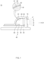
- FIG. 1 is a cross-sectional view illustrating a lamp for a vehicle according to a first embodiment of the present disclosure.
- a lamp 10 for a vehicle according to a first embodiment of the present disclosure includes a board part 30, a light source part 40, a lens part 50, and a reflection part 60. Furthermore, the lamp 10 for a vehicle according to the first embodiment of the present disclosure may further include an inner lens 70 and a housing 20.
- the board part 30 may be a printed circuit board (PCB).
- PCB printed circuit board
- the light source part 40 includes a plurality of light sources 41 that are disposed on an upper side of the board part 30 and irradiate light.
- Various elements or devices, which may emit light, may be used for the light source part 40.
- the light source 41 may be a light emitting diode (hereinafter, an LED).
- the lens part 50 is installed to surround the light source part 40 and is disposed on an upper surface of the board part 30.
- the lens part 50 is formed to be filled between the board part 30 and a reflective surface 61 of the reflection part 60. That is, a lower surface of the lens part 50 may be formed to contact the board part 30 and one surface thereof may be formed to contact the reflective surface 61 of the reflection part 60.
- a shape of the lens part 50 may be changed according to shapes of the board part 30 and the reflection part 60.
- the reflection part 60 is installed on an upper side of the board part 30, and includes the reflective surface 61 that reflects the light irradiated from the light source part 40 to change a travel path of the light.
- the reflective surface 61 is configured to contact the lens part 50, and phosphor 63 is deposited thereon.
- a phosphor layer 63 may be formed on the reflective surface 61 of the reflection part 60, which contacts the lens part.
- a method for depositing the phosphor 63 in the reflection part 60 is not limited.
- the manufactured phosphor layer 63 may be attached on a rear surface of the reflection part 60.
- the phosphor 63 may be deposited by applying the phosphor 63 on the reflective surface 61 through coating.
- the reflection part 60 may be formed of a polycarbonate material, but the present disclosure is not limited thereto.
- the phosphor 63 may be efficiently implemented without adding a separate process by depositing the phosphor 63 on the reflective surface 61 when the reflection part 60 is injection-molded.
- a uniformity of the light may be enhanced by depositing the phosphor 63 on the reflective surface 61, and images may be differentiated.
- optical patterns having various wavelengths and colors may be implemented by varying a color of the phosphor 63 deposited on the reflective surface 61 when the reflection part 60 is manufactured.
- an optical structure in which a travel path of the light irradiated from the light source 41 is changed such that the light is output, is applied, an air gap that is an interval between the light source part 40 and the reflective surface 61 or between the reflective surface 61 and the inner lens 70 may be secured to be long. Accordingly, according to the present disclosure, the light emitted from the light source 41 may be refracted/ reflected in a specific direction, and thus, diffusion of the light may be minimized and optical efficiency may be enhanced.
- the first embodiment of the present disclosure may further include the inner lens 70.
- the inner lens 70 may be disposed in the output direction D1 of the lens part 50, and the light reflected by the reflection part 60 may be output to an outer side.
- the output direction D1 may be a direction, in which the light reflected by the reflection part 60 is output to an outside, and for example, when the lamp 10 for a vehicle is a rear lamp, the output direction D1 may be a rearward direction with respect to a forward/rearward direction of the vehicle. However, the output direction D1 may be changed to a forward direction or a lateral direction according a mounting location of the lamp 10 for a vehicle.
- the inner lens 70 may be disposed in the output direction D1 of the lens part 50, and may output the light that is reflected by the reflection part 60 and passes through the lens part 50 to the outside.
- the first embodiment of the present disclosure may further include an outer lens that is spaced apart from the inner lens 70.
- the present disclosure may further include the housing 20 that is installed on a lower side of the reflection part 60. Furthermore, the board part 30, the light source part 40, the lens part 50, and the inner lens 70 may be installed between the reflection part 60 and the housing 20.
- the inner lens 70 may be fixed between the housing 20 and the reflection part 60.
- the housing 20 may function to protect the board part 30, the light source part 40, the lens part 50, and the inner lens 70 by surrounding them, together with the reflection part 60.
- the phosphor 63 may be deposited in the entire area of the reflective surface 61. That is, the first embodiment of the present disclosure may implement the phosphor layer 63 by depositing the phosphor 63 on the entire reflective surface 61 that is a surface that faces the lens part 50 of the reflection part 60.
- the reflection part 60 may reflect all the light that reaches the reflective surface 61 in the output direction D1.
- the second to sixth embodiments of the present disclosure may be different from the first embodiment of the present disclosure in the lens part 50 or the reflective surface 61. Accordingly, the second to sixth embodiments of the present disclosure may include all of the configurations of the first embodiment of the present disclosure, except for the above-described differences.
- the second to sixth embodiments of the present disclosure also may include board parts 30a, 30b, 30c, 30d, and 30e, light source parts 40a, 40b, 40c, 40d, and 40e, lens parts 50a, 50b, 50c, 50d, and 50e, reflection parts 60a, 60b, 60c, 60d, and 60e, and configurations thereof, and may include all of the inner lens 70 and housings 20a, 20b, 20c, 20d, and 20e.
- FIG. 2 is a cross-sectional view illustrating a lamp for a vehicle according to a second embodiment of the present disclosure.
- FIG. 3 is a view of a reflection part according to the second embodiment of the present disclosure, when viewed from a lower side.
- FIG. 4 is a front view illustrating the lamp for a vehicle according to the second embodiment of the present disclosure, when viewed from a front side.
- a lamp 10a for a vehicle may include the board part 30a, the light source part 40a including a plurality of light sources 41a, the lens part 50a, and the reflection part 60a including a reflective surface 61a.
- the lens part 50a may have an optic 51a that protrudes from a surface that contacts the reflection part 60a. Furthermore, the reflective surface 61a may have a groove 64a corresponding to the optic 51a.
- a shape of the optic 51a may be variously changed according to an optical pattern design specification of the applied optical system.
- the optic 51a may have a shape that extends in a leftward/rightward direction, and a plurality of optics 51a may be continuously formed along an upward/downward direction of the reflective surface 61a.
- a shape (a vertical cross-section) of the optic 51a that is perpendicular to an extension direction of the optic 51a may have a saw-tooth shape that is engaged with the groove 64a of the reflective surface 61a.
- An aspect that the groove 64a is formed to correspond to the optic 51a means that the optic 51a has a shape that is similar thereto to be accommodated in or engaged with the groove 64a.
- the optics 51a and the grooves 64a are repeatedly formed along the upward direction, and the optic 51a may be formed to become gentler as it goes in the upward direction. Furthermore, the groove 64a of the reflective surface 61a also may be formed to be gentler as it goes in the upward direction. A travel path of the light irradiated from the light source 41a may be controlled by the shapes of the groove 64a and the optic 51a.
- the light generated by the light source 41 a may be uniformly output in an output direction D1 after being reflected by the reflection part 60a, and the diffusion of the light may be minimized and optical efficiency may be increased.
- the shapes of the optic 51a and the groove 64a are not limited to those in the illustrated embodiment.
- FIG. 5 is a cross-sectional view illustrating a lamp for a vehicle according to a third embodiment of the present disclosure.
- FIG. 6 is a view of a reflection part according to the third embodiment of the present disclosure, when viewed from a lower side.
- FIG. 7 is a front view illustrating the lamp for a vehicle according to the third embodiment of the present disclosure, when viewed from a front side.
- a lamp 10b for a vehicle may include the board part 30b, the light source part 40b including a plurality of light sources 41b, the lens part 50b, and the reflection part 60b including a reflective surface 61b.
- the reflective surface 61b may include a plurality of reflective grooves 62b that are formed to be concave. Furthermore, the plurality of reflective grooves 62b may be continuously repeatedly formed in the upward/downward direction and the leftward/rightward direction of the reflective surface 61b.
- images of light distribution patterns may be variously determined by forming convexo-concave patterns on the reflective surface 61b that is a deposition area in various shapes.
- the reflective grooves 62b of a polygonal shape which are continuous in the upward/downward direction and the leftward/rightward direction, may be formed on the reflective surface 61b.
- the reflective groove 62b may have a triangular pyramid shape. Light distribution pattern images may be differentiated by forming the reflective groove 62b of the triangular pyramid shape and depositing the phosphor 63b.
- the shape of the reflective groove 62b is not limited thereto.
- FIG. 8 is a cross-sectional view illustrating a lamp for a vehicle according to a fourth embodiment of the present disclosure.
- FIG. 9 is a view of a reflection part according to the fourth embodiment of the present disclosure, when viewed from a lower side.
- FIG. 10 is a front view illustrating the lamp for a vehicle according to the fourth embodiment of the present disclosure, when viewed from a front side.
- a lamp 10c for a vehicle may include the board part 30c, the light source part 40c including a plurality of light sources 41c, the lens part 50c, and the reflection part 60c including a reflective surface 61c.
- the reflective surface 61c may include a plurality of reflective grooves 62c that are formed to be concave. Furthermore, the plurality of reflective grooves 62c may be continuously repeatedly formed in the upward/downward direction and the leftward/rightward direction of the reflective surface 61c.
- images of light distribution patterns may be variously determined by forming convexo-concave patterns on the reflective surface 61c that is a deposition area in various shapes.
- the reflective grooves 62c of a polygonal shape which are continuous in the upward/downward direction and the leftward/rightward direction, may be formed on the reflective surface 61c.
- the reflective groove 62c may have a hexagonal pyramid shape.
- a light distribution pattern image may be differentiated by forming the reflective groove 62c of the hexagonal pyramid shape and depositing the phosphor 63c.
- the shape of the reflective groove 62c is not limited thereto.
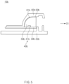
- FIG. 11 is a cross-sectional view illustrating a lamp for a vehicle according to a fifth embodiment of the present disclosure.
- FIG. 12 is a view of a reflection part according to the fifth embodiment of the present disclosure, when viewed from a lower side.
- FIG. 13 is a front view illustrating the lamp for a vehicle according to the fifth embodiment of the present disclosure, when viewed from a front side.
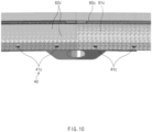
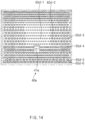
- FIG. 14 illustrates the lamp for a vehicle according to the fifth embodiment of the present disclosure, and is an enlarged view of a portion of FIG. 13 .
- a lamp 10d for a vehicle may include the board part 30d, the light source part 40d including a plurality of light sources 41d, the lens part 50d, and the reflection part 60d including a reflective surface 61d.
- the reflective surface 61d may include a deposition area 65d that is an area, in which the phosphor 63d is deposited, and a non-deposition area that is the remaining area other than the deposition area 65d.
- the deposition area may be formed at a portion of a surface of the reflective surface 61d, which faces the lens part 50d, and the phosphor 63d may be deposited to have a specific shape.
- the light that reaches the deposition area 65d may be reflected toward the output direction D1.
- the light that reaches the deposition area 65d may have a reflectivity that is higher than that of the light that reaches the non-deposition area, due to the phosphor 63d, and may have a color that is different from that of the light that reaches the non-deposition area.
- an image and a color of the lamp that is irradiated in the output direction D1 may become various. Accordingly, a lamp image having a differentiated design may be implemented by forming the deposition area 65d in a standardized pattern or an atypical shape.
- the deposition area 65d may include a plurality of unit patterns having a circular shape.
- the present disclosure is not limited thereto, and the deposition area 65d may have an elliptical or polygonal shape.
- the deposition area 65d may include a plurality of pattern groups, and each of the plurality of pattern groups may include a plurality of unit patterns having the same size.
- the sizes of the unit patterns may become larger as the pattern groups including the unit patterns are located at locations that are farther from a center of the light source 41d.
- the unit patterns disposed within a specific distance range from the light source 41d are defined as one pattern group. Then, the unit patterns included one pattern group may have the same size.
- reference numerals 65d-1, 65d-2, 65d-3, 65d-4, 65d-5, and 65d-6 denote the pattern groups located at locations that are farther from the light source 41d, in a sequence thereof.
- the sizes of the unit pattern are compared, it may be identified that the sizes of the unit patterns become larger as the unit patterns are located at locations that are farther from the light source part 40d (65d-1 ⁇ 65d-2 ⁇ 65d-3 ⁇ 65d-4 ⁇ 65d-5 ⁇ 65d-6).
- an amount of the reflected light may be to be smaller by decreasing deposition of the unit patterns that are closer to the light source 41d, and an amount of the reflected light may be to be larger by increasing deposition of the unit patterns that are farther from the light source 41d. Accordingly, a lamp image having a uniform intensity of light as a whole may be implemented regardless the distances from the light source 41d.
- FIG. 14 is a view illustrating the reflective surface 61d having a curved surface, when viewed from a lower side.
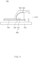
- FIG. 15 is a cross-sectional view illustrating a lamp for a vehicle according to a sixth embodiment of the present disclosure.
- FIG. 16 is a view of a reflection part according to the sixth embodiment of the present disclosure, when viewed from a lower side.
- FIG. 17 is a front view illustrating the lamp for a vehicle according to the sixth embodiment of the present disclosure, when viewed from a front side.
- FIG. 18 illustrates the lamp for a vehicle according to the fifth embodiment of the present disclosure, and is an enlarged view of a portion of FIG. 17 .
- a lamp 10e for a vehicle may include the board part 30e, the light source part 40e including a plurality of light sources 41e, the lens part 50e, and the reflection part 60e including a reflective surface 61e.
- the reflective surface 61e may include a deposition area 66e that is an area, in which the phosphor 63e is deposited, and a non-deposition area 67e that is the remaining area other than the deposition area 66e.
- the deposition area may be formed at a portion of a surface of the reflective surface 61e, which faces the lens part 50e, and the phosphor 63e may be deposited to have a specific shape. Accordingly, according to the shape of the deposition area 66e, an image and a color of the lamp that is irradiated in the output direction D1 may become various. Accordingly, a lamp image having a differentiated design may be implemented by forming the deposition area 66e in a standardized pattern or an atypical shape.
- the deposition area 66e may include a plurality of unit patterns that have a line shape and cross each other to form a lattice shape.
- the non-deposition area 67e may include a plurality of lattice areas by the plurality of unit patterns.
- Intervals between adjacent ones of the plurality of unit patterns may become larger as they are located at locations that are farther from the light source 41e.
- the size of the deposition area 66e per unit area increases as the distances between the unit pattern having the line shape becomes smaller, reflectivity may be enhanced. Furthermore, reflectivity may become lower as the size of the deposition area 66e per unit area becomes smaller. Accordingly, the reflectivity may be adjusted by adjusting the intervals between the adjacent unit patterns.
- the widths of the unit patterns may be constant (about 0.4 mm), and the intervals therebetween may become larger as the unit patterns are located at locations that are farther from the light source 41e.
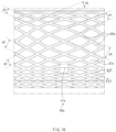
- FIG. 18 illustrates the intervals d1, d2, d3, and d4 between the unit patterns having the line shape, of which distances from the light source 41e.
- reference numerals d1, d2, d3, and d4 denote intervals between the unit patterns located at locations that are farther from the light source 41e in a sequence thereof.
- the intervals between the unit patterns are compared, it may be identified that the intervals between the unit patterns become larger as the unit patterns are located at locations that are farther from the light source 41e (d1 ⁇ d2 ⁇ d3 ⁇ d4).
- d1 when a thickness of the unit pattern having the line shape is 0.4 mm, d1 may be about 0.7 mm, d2 may be about 1.1 mm, d3 may be about 2 mm, and d4 may be about 2.6 mm.
- the present disclosure is provided for describing an example, and the thicknesses of and the intervals between the unit patterns having the line shape are not limited thereto.
- the phosphor may be implemented in the reflection part while not adding any separate process by depositing the phosphor on the reflective surface when the reflection part is injection-molded, and the image may be differentiated by enhancing optical uniformity.
- optical patterns having various wavelengths and colors may be implemented by varying a color of the phosphor deposited on the reflective surface when the reflection part is manufactured.
- a travel path of the light emitted from the light source may be controlled by securing the air gap such that the air gap is long, and thus, optical efficiency may be increased by minimizing diffusion of the light.
- the phosphor may be efficiently implemented without adding a separate process by depositing the phosphor on the reflective surface when the reflection part is injection-molded.
- a uniformity of the light may be enhanced by depositing the phosphor on the reflective surface, and images may be differentiated.
- optical patterns having various wavelengths and colors may be implemented by varying a color of the phosphor deposited on the reflective surface when the reflection part is manufactured.
- an optical structure in which a travel path of the light irradiated from the light source is changed such that the light is output, is applied, an air gap that is an interval between the light source part and the reflection surface or between the reflective surface and the inner lens may be secured to be long. Accordingly, according to the present disclosure, the light emitted from the light source 41 may be refracted and reflected in a specific direction, and thus, diffusion of the light may be minimized and optical efficiency may be enhanced.
Landscapes
- Engineering & Computer Science (AREA)
- General Engineering & Computer Science (AREA)
- Physics & Mathematics (AREA)
- Microelectronics & Electronic Packaging (AREA)
- Optics & Photonics (AREA)
- Geometry (AREA)
- Non-Portable Lighting Devices Or Systems Thereof (AREA)
Abstract
Description
- This application claims the benefit of priority to
Korean Patent Application No. 1 0-2022-0140602, filed in the Korean Intellectual Property Office on October 27, 2022 - The present disclosure relates to a lamp for a vehicle.
- Conventionally, according to a high-resolution LED module, phosphor has to be injected and coated on a surface of an LED module to implement various colors. Accordingly, a process for injection-molding the phosphor has to be added when the LED module is manufactured, and LED modules are classified into several categories. According, work efficiency is lowered when the LED module is manufactured.
- Furthermore, according to the conventional LED module, the light generated by the light source is diffused in directions, other than a forward direction, and an amount of the light is lost.
- Accordingly, it is necessary to develop an optical system technology, by which production efficiency may be enhanced when phosphor is formed while optical efficiency is also enhanced.
- The present disclosure has been made to solve the above-mentioned problems occurring in the prior art while advantages achieved by the prior art are maintained intact.
- An aspect of the present disclosure provides a lamp for a vehicle that enhances production efficiency by depositing phosphor on a reflection part while not adding a separate process.
- Another aspect of the present disclosure provides a lamp for a vehicle that enhances optical uniformity by depositing phosphor on a reflective surface and differentiates an image.
- Another aspect of the present disclosure provides a lamp for a vehicle that implements an image pattern having various wavelengths and colors.
- The technical problems to be solved by the present disclosure are not limited to the aforementioned problems, and any other technical problems not mentioned herein will be clearly understood from the following description by those skilled in the art to which the present disclosure pertains.
- According to an aspect of the present disclosure, a lamp for a vehicle includes a board part, a light source part disposed on an upper surface of the board part and including a plurality of light sources that irradiate light, a lens part installed to surround the light source part and disposed on an upper side of the board part, and a reflection part installed on an upper side of the board part, and including a reflective surface that reflects the light irradiated from the light source part to change a travel path of the light, and the reflective surface contacts the lens part and phosphor is deposited thereon.
- The lamp may further include an inner lens disposed, when a direction, in which the light reflected by the reflection part is output, is defined as an output direction, on the output direction of the lens part that outputs the light reflected by the reflection part to an outside.
- The lamp may further include a housing installed on a lower side of the reflection part, and the board part, the light source part, the lens part, and the inner lens may be installed between the reflection part and the housing.
- The phosphor may be deposited in an entire area of the reflective surface.
- Optics protruding from a surface of the lens part, which contacts the reflection part, may be formed in the lens part, and the reflective surface may have grooves corresponding to the optics.
- The optics and the grooves may be repeatedly formed along an upward direction, and the optics may be formed to become gentler as they go in the upward direction.
- The reflective surface may include a plurality of reflective grooves that are recessed, and the plurality of reflective grooves may be continuously repeatedly formed in an upward/downward direction and a leftward/rightward direction of the reflective surface.
- The reflective grooves may have a triangular pyramid shape.
- The reflective grooves may have a hexagonal pyramid shape.
- The reflective surface may include a deposition area that is an area, in which the phosphor is deposited, and a non-deposition area that is the remaining area other than the deposition area.
- The deposition area may include a plurality of unit patterns having a circular shape.
- The deposition area may include a plurality of pattern groups, each of the plurality of pattern groups may include a plurality of unit patterns having the same size, and sizes of the unit patterns may become larger as the pattern groups of the unit patterns are located at locations that are farther from a center of the light source.
- The deposition area may have a plurality of unit patterns having a line shape and crossing each other to form a lattice shape, and the non-deposition area may include a plurality of lattice areas by the plurality of unit patterns.
- Intervals between adjacent ones of the plurality of unit patterns may become larger as the adjacent ones are located at locations that are farther from the light source.
- The above and other objects, features and advantages of the present disclosure will be more apparent from the following detailed description taken in conjunction with the accompanying drawings:
-
FIG. 1 is a cross-sectional view illustrating a lamp for a vehicle according to a first embodiment of the present disclosure; -
FIG. 2 is a cross-sectional view illustrating a lamp for a vehicle according to a second embodiment of the present disclosure; -
FIG. 3 is a view of a reflection part according to the second embodiment of the present disclosure, when viewed from a lower side; -
FIG. 4 is a front view illustrating the lamp for a vehicle according to the second embodiment of the present disclosure, when viewed from a front side; -
FIG. 5 is a cross-sectional view illustrating a lamp for a vehicle according to a third embodiment of the present disclosure; -
FIG. 6 is a view of a reflection part according to the third embodiment of the present disclosure, when viewed from a lower side; -
FIG. 7 is a front view illustrating the lamp for a vehicle according to the third embodiment of the present disclosure, when viewed from a front side; -
FIG. 8 is a cross-sectional view illustrating a lamp for a vehicle according to a fourth embodiment of the present disclosure; -
FIG. 9 is a view of a reflection part according to the fourth embodiment of the present disclosure, when viewed from a lower side; -
FIG. 10 is a front view illustrating the lamp for a vehicle according to the fourth embodiment of the present disclosure, when viewed from a front side; -
FIG. 11 is a cross-sectional view illustrating a lamp for a vehicle according to a fifth embodiment of the present disclosure; -
FIG. 12 is a view of a reflection part according to the fifth embodiment of the present disclosure, when viewed from a lower side; -
FIG. 13 is a front view illustrating the lamp for a vehicle according to the fifth embodiment of the present disclosure, when viewed from a front side; -
FIG. 14 illustrates the lamp for a vehicle according to the fifth embodiment of the present disclosure, and is an enlarged view of a portion ofFIG. 13 ; -
FIG. 15 is a cross-sectional view illustrating a lamp for a vehicle according to a sixth embodiment of the present disclosure; -
FIG. 16 is a view of a reflection part according to the sixth embodiment of the present disclosure, when viewed from a lower side; -
FIG. 17 is a front view illustrating the lamp for a vehicle according to the sixth embodiment of the present disclosure, when viewed from a front side; and -
FIG. 18 illustrates the lamp for a vehicle according to the fifth embodiment of the present disclosure, and is an enlarged view of a portion ofFIG. 17 . - Hereinafter, embodiments of the present disclosure will be described in detail with reference to the accompanying drawings.
- First, the embodiments described herein are embodiments that are suitable for understanding the technical features of a lamp for a vehicle according to the present disclosure. However, the present disclosure is not limited to the embodiment described below or the technical features of the present disclosure are not limited by the described embodiments, and the present disclosure may be variously modified without departing from the technical scope of the present disclosure.
-
FIG. 1 is a cross-sectional view illustrating a lamp for a vehicle according to a first embodiment of the present disclosure. - Referring to
FIG. 1 , alamp 10 for a vehicle according to a first embodiment of the present disclosure includes aboard part 30, alight source part 40, alens part 50, and areflection part 60. Furthermore, thelamp 10 for a vehicle according to the first embodiment of the present disclosure may further include aninner lens 70 and ahousing 20. - The
board part 30 may be a printed circuit board (PCB). - The
light source part 40 includes a plurality oflight sources 41 that are disposed on an upper side of theboard part 30 and irradiate light. Various elements or devices, which may emit light, may be used for thelight source part 40. For example, thelight source 41 may be a light emitting diode (hereinafter, an LED). - The
lens part 50 is installed to surround thelight source part 40 and is disposed on an upper surface of theboard part 30. Thelens part 50 is formed to be filled between theboard part 30 and areflective surface 61 of thereflection part 60. That is, a lower surface of thelens part 50 may be formed to contact theboard part 30 and one surface thereof may be formed to contact thereflective surface 61 of thereflection part 60. A shape of thelens part 50 may be changed according to shapes of theboard part 30 and thereflection part 60. - The
reflection part 60 is installed on an upper side of theboard part 30, and includes thereflective surface 61 that reflects the light irradiated from thelight source part 40 to change a travel path of the light. - Furthermore, the
reflective surface 61 is configured to contact thelens part 50, andphosphor 63 is deposited thereon. - In detail, a
phosphor layer 63 may be formed on thereflective surface 61 of thereflection part 60, which contacts the lens part. A method for depositing thephosphor 63 in thereflection part 60 is not limited. For example, after thephosphor layer 63 is manufactured and thereflection part 60 is injection-molded, the manufacturedphosphor layer 63 may be attached on a rear surface of thereflection part 60. Alternatively, for example, after injection-molding thereflection part 60, thephosphor 63 may be deposited by applying thephosphor 63 on thereflective surface 61 through coating. For example, thereflection part 60 may be formed of a polycarbonate material, but the present disclosure is not limited thereto. - Accordingly, according to an embodiment of the present disclosure, the
phosphor 63 may be efficiently implemented without adding a separate process by depositing thephosphor 63 on thereflective surface 61 when thereflection part 60 is injection-molded. - Furthermore, according to an embodiment of the present disclosure, a uniformity of the light may be enhanced by depositing the
phosphor 63 on thereflective surface 61, and images may be differentiated. - Furthermore, according to an embodiment of the present disclosure, optical patterns having various wavelengths and colors may be implemented by varying a color of the
phosphor 63 deposited on thereflective surface 61 when thereflection part 60 is manufactured. - Furthermore, according to an embodiment of the present disclosure, since an optical structure, in which a travel path of the light irradiated from the
light source 41 is changed such that the light is output, is applied, an air gap that is an interval between thelight source part 40 and thereflective surface 61 or between thereflective surface 61 and theinner lens 70 may be secured to be long. Accordingly, according to the present disclosure, the light emitted from thelight source 41 may be refracted/ reflected in a specific direction, and thus, diffusion of the light may be minimized and optical efficiency may be enhanced. - Meanwhile, the first embodiment of the present disclosure may further include the
inner lens 70. When a direction, in which the light reflected by thereflection part 60 is output, is defined as an output direction D1, theinner lens 70 may be disposed in the output direction D1 of thelens part 50, and the light reflected by thereflection part 60 may be output to an outer side. - In detail, the output direction D1 may be a direction, in which the light reflected by the
reflection part 60 is output to an outside, and for example, when thelamp 10 for a vehicle is a rear lamp, the output direction D1 may be a rearward direction with respect to a forward/rearward direction of the vehicle. However, the output direction D1 may be changed to a forward direction or a lateral direction according a mounting location of thelamp 10 for a vehicle. - The
inner lens 70 may be disposed in the output direction D1 of thelens part 50, and may output the light that is reflected by thereflection part 60 and passes through thelens part 50 to the outside. Although not illustrated, the first embodiment of the present disclosure may further include an outer lens that is spaced apart from theinner lens 70. - Meanwhile, the present disclosure may further include the
housing 20 that is installed on a lower side of thereflection part 60. Furthermore, theboard part 30, thelight source part 40, thelens part 50, and theinner lens 70 may be installed between thereflection part 60 and thehousing 20. - For example, the
inner lens 70 may be fixed between thehousing 20 and thereflection part 60. Thehousing 20 may function to protect theboard part 30, thelight source part 40, thelens part 50, and theinner lens 70 by surrounding them, together with thereflection part 60. - Meanwhile, referring to
FIG. 1 , thephosphor 63 may be deposited in the entire area of thereflective surface 61. That is, the first embodiment of the present disclosure may implement thephosphor layer 63 by depositing thephosphor 63 on the entirereflective surface 61 that is a surface that faces thelens part 50 of thereflection part 60. - Accordingly, the
reflection part 60 may reflect all the light that reaches thereflective surface 61 in the output direction D1. - Hereinafter, second to sixth embodiments of the present disclosure will be described with reference to
FIGS. 2 to 18 . The second to sixth embodiments of the present disclosure may be different from the first embodiment of the present disclosure in thelens part 50 or thereflective surface 61. Accordingly, the second to sixth embodiments of the present disclosure may include all of the configurations of the first embodiment of the present disclosure, except for the above-described differences. For example, the second to sixth embodiments of the present disclosure also may includeboard parts light source parts lens parts reflection parts inner lens 70 andhousings - Hereinafter, a repeated description of the same configurations as the above-described ones will be omitted.
-
FIG. 2 is a cross-sectional view illustrating a lamp for a vehicle according to a second embodiment of the present disclosure.FIG. 3 is a view of a reflection part according to the second embodiment of the present disclosure, when viewed from a lower side.FIG. 4 is a front view illustrating the lamp for a vehicle according to the second embodiment of the present disclosure, when viewed from a front side. - Referring to
FIGS. 2 to 4 , alamp 10a for a vehicle according to a second embodiment of the present disclosure may include theboard part 30a, thelight source part 40a including a plurality oflight sources 41a, thelens part 50a, and thereflection part 60a including areflective surface 61a. - Furthermore, the
lens part 50a may have an optic 51a that protrudes from a surface that contacts thereflection part 60a. Furthermore, thereflective surface 61a may have agroove 64a corresponding to theoptic 51a. - A shape of the optic 51a may be variously changed according to an optical pattern design specification of the applied optical system. For example, the
optic 51a may have a shape that extends in a leftward/rightward direction, and a plurality ofoptics 51a may be continuously formed along an upward/downward direction of thereflective surface 61a. - Then, a shape (a vertical cross-section) of the optic 51a that is perpendicular to an extension direction of the optic 51a may have a saw-tooth shape that is engaged with the
groove 64a of thereflective surface 61a. An aspect that thegroove 64a is formed to correspond to the optic 51a means that the optic 51a has a shape that is similar thereto to be accommodated in or engaged with thegroove 64a. - Furthermore, for example, the
optics 51a and thegrooves 64a are repeatedly formed along the upward direction, and the optic 51a may be formed to become gentler as it goes in the upward direction. Furthermore, thegroove 64a of thereflective surface 61a also may be formed to be gentler as it goes in the upward direction. A travel path of the light irradiated from thelight source 41a may be controlled by the shapes of thegroove 64a and the optic 51a. - According to the design of the shapes of the optic 51a and the
groove 64a, the light generated by thelight source 41 a may be uniformly output in an output direction D1 after being reflected by thereflection part 60a, and the diffusion of the light may be minimized and optical efficiency may be increased. However, the shapes of the optic 51a and thegroove 64a are not limited to those in the illustrated embodiment. -
FIG. 5 is a cross-sectional view illustrating a lamp for a vehicle according to a third embodiment of the present disclosure.FIG. 6 is a view of a reflection part according to the third embodiment of the present disclosure, when viewed from a lower side.FIG. 7 is a front view illustrating the lamp for a vehicle according to the third embodiment of the present disclosure, when viewed from a front side. - Referring to
FIGS. 5 to 7 , alamp 10b for a vehicle according to a third embodiment of the present disclosure may include theboard part 30b, thelight source part 40b including a plurality oflight sources 41b, thelens part 50b, and thereflection part 60b including areflective surface 61b. - Furthermore, the
reflective surface 61b may include a plurality ofreflective grooves 62b that are formed to be concave. Furthermore, the plurality ofreflective grooves 62b may be continuously repeatedly formed in the upward/downward direction and the leftward/rightward direction of thereflective surface 61b. - In detail, in the
reflection part 60b according to the third embodiment, images of light distribution patterns may be variously determined by forming convexo-concave patterns on thereflective surface 61b that is a deposition area in various shapes. For example, thereflective grooves 62b of a polygonal shape, which are continuous in the upward/downward direction and the leftward/rightward direction, may be formed on thereflective surface 61b. - For example, the
reflective groove 62b may have a triangular pyramid shape. Light distribution pattern images may be differentiated by forming thereflective groove 62b of the triangular pyramid shape and depositing thephosphor 63b. However, the shape of thereflective groove 62b is not limited thereto. -
FIG. 8 is a cross-sectional view illustrating a lamp for a vehicle according to a fourth embodiment of the present disclosure.FIG. 9 is a view of a reflection part according to the fourth embodiment of the present disclosure, when viewed from a lower side.FIG. 10 is a front view illustrating the lamp for a vehicle according to the fourth embodiment of the present disclosure, when viewed from a front side. - Referring to
FIGS. 8 to 10 , alamp 10c for a vehicle according to a fourth embodiment of the present disclosure may include theboard part 30c, thelight source part 40c including a plurality oflight sources 41c, thelens part 50c, and thereflection part 60c including areflective surface 61c. - Furthermore, the
reflective surface 61c may include a plurality ofreflective grooves 62c that are formed to be concave. Furthermore, the plurality ofreflective grooves 62c may be continuously repeatedly formed in the upward/downward direction and the leftward/rightward direction of thereflective surface 61c. - In detail, in the
reflection part 60c according to the fourth embodiment, images of light distribution patterns may be variously determined by forming convexo-concave patterns on thereflective surface 61c that is a deposition area in various shapes. For example, thereflective grooves 62c of a polygonal shape, which are continuous in the upward/downward direction and the leftward/rightward direction, may be formed on thereflective surface 61c. - For example, the
reflective groove 62c may have a hexagonal pyramid shape. A light distribution pattern image may be differentiated by forming thereflective groove 62c of the hexagonal pyramid shape and depositing thephosphor 63c. However, the shape of thereflective groove 62c is not limited thereto. -
FIG. 11 is a cross-sectional view illustrating a lamp for a vehicle according to a fifth embodiment of the present disclosure.FIG. 12 is a view of a reflection part according to the fifth embodiment of the present disclosure, when viewed from a lower side.FIG. 13 is a front view illustrating the lamp for a vehicle according to the fifth embodiment of the present disclosure, when viewed from a front side.FIG. 14 illustrates the lamp for a vehicle according to the fifth embodiment of the present disclosure, and is an enlarged view of a portion ofFIG. 13 . - Referring to
FIGS. 11 to 14 , alamp 10d for a vehicle according to a fifth embodiment of the present disclosure may include theboard part 30d, thelight source part 40d including a plurality oflight sources 41d, thelens part 50d, and thereflection part 60d including areflective surface 61d. - Furthermore, the
reflective surface 61d may include adeposition area 65d that is an area, in which the phosphor 63d is deposited, and a non-deposition area that is the remaining area other than thedeposition area 65d. - In detail, the deposition area may be formed at a portion of a surface of the
reflective surface 61d, which faces thelens part 50d, and the phosphor 63d may be deposited to have a specific shape. Among the light that is emitted from thelight source part 40d and reaches thereflective surface 61d, the light that reaches thedeposition area 65d may be reflected toward the output direction D1. Then, the light that reaches thedeposition area 65d may have a reflectivity that is higher than that of the light that reaches the non-deposition area, due to the phosphor 63d, and may have a color that is different from that of the light that reaches the non-deposition area. - Accordingly, according to the shape of the
deposition area 65d, an image and a color of the lamp that is irradiated in the output direction D1 may become various. Accordingly, a lamp image having a differentiated design may be implemented by forming thedeposition area 65d in a standardized pattern or an atypical shape. - For example, the
deposition area 65d may include a plurality of unit patterns having a circular shape. However, the present disclosure is not limited thereto, and thedeposition area 65d may have an elliptical or polygonal shape. - Furthermore, for example, the
deposition area 65d may include a plurality of pattern groups, and each of the plurality of pattern groups may include a plurality of unit patterns having the same size. - Furthermore, the sizes of the unit patterns may become larger as the pattern groups including the unit patterns are located at locations that are farther from a center of the
light source 41d. - In detail, in the specification, among the unit patterns that form the
deposition area 65d, the unit patterns disposed within a specific distance range from thelight source 41d are defined as one pattern group. Then, the unit patterns included one pattern group may have the same size. - For example, referring to
FIG. 14 ,reference numerals 65d-1, 65d-2, 65d-3, 65d-4, 65d-5, and 65d-6 denote the pattern groups located at locations that are farther from thelight source 41d, in a sequence thereof. When the sizes of the unit pattern are compared, it may be identified that the sizes of the unit patterns become larger as the unit patterns are located at locations that are farther from thelight source part 40d (65d-1 <65d-2<65d-3<65d-4<65d-5<65d-6). - In this way, an amount of the reflected light may be to be smaller by decreasing deposition of the unit patterns that are closer to the
light source 41d, and an amount of the reflected light may be to be larger by increasing deposition of the unit patterns that are farther from thelight source 41d. Accordingly, a lamp image having a uniform intensity of light as a whole may be implemented regardless the distances from thelight source 41d. - The reason why some of the shapes of the unit patterns are viewed as if they were not circular but elliptical in
FIG. 14 is that it is a view illustrating thereflective surface 61d having a curved surface, when viewed from a lower side. -
FIG. 15 is a cross-sectional view illustrating a lamp for a vehicle according to a sixth embodiment of the present disclosure.FIG. 16 is a view of a reflection part according to the sixth embodiment of the present disclosure, when viewed from a lower side.FIG. 17 is a front view illustrating the lamp for a vehicle according to the sixth embodiment of the present disclosure, when viewed from a front side.FIG. 18 illustrates the lamp for a vehicle according to the fifth embodiment of the present disclosure, and is an enlarged view of a portion ofFIG. 17 . - Referring to
FIGS. 15 to 18 , alamp 10e for a vehicle according to a sixth embodiment of the present disclosure may include theboard part 30e, thelight source part 40e including a plurality oflight sources 41e, thelens part 50e, and thereflection part 60e including a reflective surface 61e. - Furthermore, the reflective surface 61e may include a
deposition area 66e that is an area, in which the phosphor 63e is deposited, and anon-deposition area 67e that is the remaining area other than thedeposition area 66e. - In detail, the deposition area may be formed at a portion of a surface of the reflective surface 61e, which faces the
lens part 50e, and the phosphor 63e may be deposited to have a specific shape. Accordingly, according to the shape of thedeposition area 66e, an image and a color of the lamp that is irradiated in the output direction D1 may become various. Accordingly, a lamp image having a differentiated design may be implemented by forming thedeposition area 66e in a standardized pattern or an atypical shape. - For example, the
deposition area 66e may include a plurality of unit patterns that have a line shape and cross each other to form a lattice shape. Furthermore, thenon-deposition area 67e may include a plurality of lattice areas by the plurality of unit patterns. - Intervals between adjacent ones of the plurality of unit patterns may become larger as they are located at locations that are farther from the
light source 41e. - In detail, because the size of the
deposition area 66e per unit area increases as the distances between the unit pattern having the line shape becomes smaller, reflectivity may be enhanced. Furthermore, reflectivity may become lower as the size of thedeposition area 66e per unit area becomes smaller. Accordingly, the reflectivity may be adjusted by adjusting the intervals between the adjacent unit patterns. - Accordingly, in the unit patterns having the line shape according to the sixth embodiment, the widths of the unit patterns may be constant (about 0.4 mm), and the intervals therebetween may become larger as the unit patterns are located at locations that are farther from the
light source 41e. - For example,
FIG. 18 illustrates the intervals d1, d2, d3, and d4 between the unit patterns having the line shape, of which distances from thelight source 41e. Referring toFIG. 18 , reference numerals d1, d2, d3, and d4 denote intervals between the unit patterns located at locations that are farther from thelight source 41e in a sequence thereof. When the intervals between the unit patterns are compared, it may be identified that the intervals between the unit patterns become larger as the unit patterns are located at locations that are farther from thelight source 41e (d1 <d2<d3<d4). - As an example, when a thickness of the unit pattern having the line shape is 0.4 mm, d1 may be about 0.7 mm, d2 may be about 1.1 mm, d3 may be about 2 mm, and d4 may be about 2.6 mm. However, the present disclosure is provided for describing an example, and the thicknesses of and the intervals between the unit patterns having the line shape are not limited thereto.
- The reason why the lattice shape that is the
non-deposition area 67e is viewed as if they were not rectangular but rhombic inFIGS. 16 to 18 is that the reflective surface 61e having the curved shape is viewed from a lower side. - According to the embodiment of the present disclosure, the phosphor may be implemented in the reflection part while not adding any separate process by depositing the phosphor on the reflective surface when the reflection part is injection-molded, and the image may be differentiated by enhancing optical uniformity.
- Furthermore, according to the embodiment of the present disclosure, optical patterns having various wavelengths and colors may be implemented by varying a color of the phosphor deposited on the reflective surface when the reflection part is manufactured.
- Furthermore, according to the embodiment of the present disclosure, a travel path of the light emitted from the light source may be controlled by securing the air gap such that the air gap is long, and thus, optical efficiency may be increased by minimizing diffusion of the light.
- According to the embodiment of the present disclosure, the phosphor may be efficiently implemented without adding a separate process by depositing the phosphor on the reflective surface when the reflection part is injection-molded.
- Furthermore, according to an embodiment of the present disclosure, a uniformity of the light may be enhanced by depositing the phosphor on the reflective surface, and images may be differentiated.
- Furthermore, according to the embodiment of the present disclosure, optical patterns having various wavelengths and colors may be implemented by varying a color of the phosphor deposited on the reflective surface when the reflection part is manufactured.
- Furthermore, according to an embodiment of the present disclosure, because an optical structure, in which a travel path of the light irradiated from the light source is changed such that the light is output, is applied, an air gap that is an interval between the light source part and the reflection surface or between the reflective surface and the inner lens may be secured to be long. Accordingly, according to the present disclosure, the light emitted from the
light source 41 may be refracted and reflected in a specific direction, and thus, diffusion of the light may be minimized and optical efficiency may be enhanced. - Although the specific embodiments of the present disclosure have been described until now, the spirit and scope of the present disclosure are not limited to the specific embodiments, and may be variously corrected and modified by an ordinary person in the art, to which the present disclosure pertains, without changing the essence of the present disclosure claimed in the claims.
Claims (14)
- A lamp for a vehicle comprising:a board part;a light source part disposed on an upper surface of the board part and comprising a plurality of light sources that irradiate light;a lens part installed to surround the light source part and disposed on an upper side of the board part; anda reflection part installed on an upper side of the board part, and comprising a reflective surface that reflects the light irradiated from the light source part to change a travel path of the light,wherein the reflective surface is configured to contact the lens part and phosphor is deposited thereon.
- The lamp of claim 1, further comprising:
an inner lens disposed on an output direction of the lens part, wherein the output direction is a direction in which the light reflected by the reflection part is output, and the inner lens is configured to output the light reflected by the reflection part to an outside of the lamp. - The lamp of claim 2, further comprising:a housing installed on a lower side of the reflection part,wherein the board part, the light source part, the lens part, and the inner lens are installed between the reflection part and the housing.
- The lamp of any one of claims 1 to 3, wherein the phosphor is deposited in an entire area of the reflective surface.
- The lamp of any one of claims 1 to 4, wherein optics protruding from a surface of the lens part, which contacts the reflection part, are formed in the lens part, and the reflective surface has grooves corresponding to the optics.
- The lamp of claim 5, wherein the optics and the grooves are repeatedly formed along an upward direction, and the optics are formed to become gentler as they go in the upward direction.
- The lamp of any one of claims 1 to 6, wherein the reflective surface comprises a plurality of reflective grooves that are recessed, and the plurality of reflective grooves are repeatedly formed in an upward/downward direction and a leftward/rightward direction of the reflective surface.
- The lamp of claim 7, wherein the reflective grooves have a triangular pyramid shape.
- The lamp of claim 7, wherein the reflective grooves have a hexagonal pyramid shape.
- The lamp of any one of claims 1 to 9, wherein the reflective surface comprises:a deposition area that is an area in which the phosphor is deposited; anda non-deposition area that is a remaining area other than the deposition area.
- The lamp of claim 10, wherein the deposition area comprises a plurality of unit patterns having a circular shape.
- The lamp of claim 11, wherein the deposition area comprises a plurality of pattern groups, each of the plurality of pattern groups comprises a plurality of unit patterns having a same size, and sizes of the unit patterns become larger as the pattern groups of the unit patterns are located at locations that are farther from a center of the light source.
- The lamp of any one of claims 10 to 12, wherein the deposition area has a plurality of unit patterns having a line shape and crossing each other to form a lattice shape, and the non-deposition area comprises a plurality of lattice areas by the plurality of unit patterns.
- The lamp of claim 13, wherein intervals between adjacent ones of the plurality of unit patterns become larger as the adjacent ones are located at locations that are farther from the light source.
Applications Claiming Priority (1)
| Application Number | Priority Date | Filing Date | Title |
|---|---|---|---|
| KR1020220140602A KR20240059398A (en) | 2022-10-27 | 2022-10-27 | Lamp for vehicle |
Publications (2)
| Publication Number | Publication Date |
|---|---|
| EP4361498A1 true EP4361498A1 (en) | 2024-05-01 |
| EP4361498B1 EP4361498B1 (en) | 2026-02-04 |
Family
ID=84519832
Family Applications (1)
| Application Number | Title | Priority Date | Filing Date |
|---|---|---|---|
| EP22213068.4A Active EP4361498B1 (en) | 2022-10-27 | 2022-12-13 | Lamp for vehicle |
Country Status (5)
| Country | Link |
|---|---|
| US (1) | US11885471B1 (en) |
| EP (1) | EP4361498B1 (en) |
| JP (1) | JP2024064926A (en) |
| KR (1) | KR20240059398A (en) |
| CN (1) | CN117948562A (en) |
Citations (7)
| Publication number | Priority date | Publication date | Assignee | Title |
|---|---|---|---|---|
| DE102011081919A1 (en) * | 2011-08-31 | 2013-02-28 | Automotive Lighting Reutlingen Gmbh | Light module for use in headlight of motor car, has wavelength converter arranged separately from LED at predetermined distance from beam-forming elements, where converter is provided in optical path of blue colored light emitted by LED |
| US20150034987A1 (en) * | 2013-07-30 | 2015-02-05 | Nichia Corporation | Light emitting device and method for manufacturing light emitting device |
| DE102014203245A1 (en) * | 2014-02-24 | 2015-08-27 | Automotive Lighting Reutlingen Gmbh | Lighting device of a motor vehicle |
| EP3112742A1 (en) * | 2015-06-22 | 2017-01-04 | ZKW Group GmbH | Lighting device for a motor vehicle with luminescent elements |
| WO2020200753A1 (en) * | 2019-04-05 | 2020-10-08 | HELLA GmbH & Co. KGaA | Illumination device for vehicles |
| WO2021182825A1 (en) * | 2020-03-09 | 2021-09-16 | 엘지이노텍 주식회사 | Lighting module and lighting device comprising same |
| EP4008950A1 (en) * | 2019-08-01 | 2022-06-08 | LG Innotek Co., Ltd. | Lighting device |
Family Cites Families (4)
| Publication number | Priority date | Publication date | Assignee | Title |
|---|---|---|---|---|
| KR20180063541A (en) * | 2016-12-02 | 2018-06-12 | 엘지전자 주식회사 | poly crystal phosphor film and method for fabricating the same and vehicle lamp apparatus for using the same |
| JP2019061855A (en) * | 2017-09-26 | 2019-04-18 | パナソニックIpマネジメント株式会社 | Light emitting device for movable body, lighting device for movable body, and movable body |
| CN108679196B (en) | 2018-07-23 | 2020-10-16 | 江苏太平洋齿轮传动有限公司 | Spherical involute straight-tooth bevel gear pair and tooth profile modification method thereof |
| FR3103877B1 (en) * | 2019-11-28 | 2022-07-08 | Valeo Vision | Optical element and light module of a motor vehicle equipped with such an optical element |
-
2022
- 2022-10-27 KR KR1020220140602A patent/KR20240059398A/en active Pending
- 2022-12-13 US US18/065,593 patent/US11885471B1/en active Active
- 2022-12-13 EP EP22213068.4A patent/EP4361498B1/en active Active
- 2022-12-26 CN CN202211674129.1A patent/CN117948562A/en active Pending
- 2022-12-26 JP JP2022208531A patent/JP2024064926A/en active Pending
Patent Citations (7)
| Publication number | Priority date | Publication date | Assignee | Title |
|---|---|---|---|---|
| DE102011081919A1 (en) * | 2011-08-31 | 2013-02-28 | Automotive Lighting Reutlingen Gmbh | Light module for use in headlight of motor car, has wavelength converter arranged separately from LED at predetermined distance from beam-forming elements, where converter is provided in optical path of blue colored light emitted by LED |
| US20150034987A1 (en) * | 2013-07-30 | 2015-02-05 | Nichia Corporation | Light emitting device and method for manufacturing light emitting device |
| DE102014203245A1 (en) * | 2014-02-24 | 2015-08-27 | Automotive Lighting Reutlingen Gmbh | Lighting device of a motor vehicle |
| EP3112742A1 (en) * | 2015-06-22 | 2017-01-04 | ZKW Group GmbH | Lighting device for a motor vehicle with luminescent elements |
| WO2020200753A1 (en) * | 2019-04-05 | 2020-10-08 | HELLA GmbH & Co. KGaA | Illumination device for vehicles |
| EP4008950A1 (en) * | 2019-08-01 | 2022-06-08 | LG Innotek Co., Ltd. | Lighting device |
| WO2021182825A1 (en) * | 2020-03-09 | 2021-09-16 | 엘지이노텍 주식회사 | Lighting module and lighting device comprising same |
Also Published As
| Publication number | Publication date |
|---|---|
| KR20240059398A (en) | 2024-05-07 |
| CN117948562A (en) | 2024-04-30 |
| EP4361498B1 (en) | 2026-02-04 |
| US11885471B1 (en) | 2024-01-30 |
| JP2024064926A (en) | 2024-05-14 |
Similar Documents
| Publication | Publication Date | Title |
|---|---|---|
| KR100499133B1 (en) | Backlight unit | |
| KR102219601B1 (en) | Light guide plate, surface light source device, display device and electronic device | |
| EP1048085B1 (en) | Led module and luminaire | |
| KR100590535B1 (en) | Backlight unit | |
| US6799860B2 (en) | Point light source-oriented light guiding means and lighting unit utilizing the same | |
| CN103080995B (en) | Light-emitting device | |
| KR102580682B1 (en) | Light unit and Lamp unit for automobile of using the same | |
| JP6675437B2 (en) | VEHICLE DUAL-FUNCTION LIGHTING MODULE AND DUAL-FUNCTION LIGHTING SET | |
| EP1862730A1 (en) | Planar illumination device | |
| JP2001035230A (en) | Planar lighting device | |
| JP2000011723A (en) | Planar lighting device | |
| US20250207748A1 (en) | Lighting device | |
| JP2022031731A (en) | Light emitting device and its manufacturing method | |
| JP6989782B2 (en) | Light emitting device and its manufacturing method | |
| CN111025743A (en) | Light source module and display device | |
| JPH08327807A (en) | Planar light source device | |
| EP4361498B1 (en) | Lamp for vehicle | |
| JP4389529B2 (en) | Surface illumination device and light guide plate | |
| JP2013191403A (en) | Side-turn lamp for door mirror | |
| US12510706B2 (en) | Optical module | |
| US20190146141A1 (en) | Lamp assembly and its frameless panel light | |
| EP4328089A1 (en) | Light-emitting unit and vehicular lamp | |
| WO2012114553A1 (en) | Light guiding member and light emitting device provided with same | |
| US11815236B2 (en) | LED module and vehicle including same | |
| US20220291521A1 (en) | Light guide, illuminator, and stereoscopic display |
Legal Events
| Date | Code | Title | Description |
|---|---|---|---|
| PUAI | Public reference made under article 153(3) epc to a published international application that has entered the european phase |
Free format text: ORIGINAL CODE: 0009012 |
|
| STAA | Information on the status of an ep patent application or granted ep patent |
Free format text: STATUS: REQUEST FOR EXAMINATION WAS MADE |
|
| 17P | Request for examination filed |
Effective date: 20230113 |
|
| AK | Designated contracting states |
Kind code of ref document: A1 Designated state(s): AL AT BE BG CH CY CZ DE DK EE ES FI FR GB GR HR HU IE IS IT LI LT LU LV MC ME MK MT NL NO PL PT RO RS SE SI SK SM TR |
|
| RBV | Designated contracting states (corrected) |
Designated state(s): AL AT BE BG CH CY CZ DE DK EE ES FI FR GB GR HR HU IE IS IT LI LT LU LV MC ME MK MT NL NO PL PT RO RS SE SI SK SM TR |
|
| STAA | Information on the status of an ep patent application or granted ep patent |
Free format text: STATUS: EXAMINATION IS IN PROGRESS |
|
| 17Q | First examination report despatched |
Effective date: 20250114 |
|
| GRAP | Despatch of communication of intention to grant a patent |
Free format text: ORIGINAL CODE: EPIDOSNIGR1 |
|
| STAA | Information on the status of an ep patent application or granted ep patent |
Free format text: STATUS: GRANT OF PATENT IS INTENDED |
|
| INTG | Intention to grant announced |
Effective date: 20250917 |
|
| GRAS | Grant fee paid |
Free format text: ORIGINAL CODE: EPIDOSNIGR3 |
|
| GRAA | (expected) grant |
Free format text: ORIGINAL CODE: 0009210 |
|
| STAA | Information on the status of an ep patent application or granted ep patent |
Free format text: STATUS: THE PATENT HAS BEEN GRANTED |
|
| P01 | Opt-out of the competence of the unified patent court (upc) registered |
Free format text: CASE NUMBER: UPC_APP_0018090_4361498/2025 Effective date: 20251217 |
|
| AK | Designated contracting states |
Kind code of ref document: B1 Designated state(s): AL AT BE BG CH CY CZ DE DK EE ES FI FR GB GR HR HU IE IS IT LI LT LU LV MC ME MK MT NL NO PL PT RO RS SE SI SK SM TR |
|
| REG | Reference to a national code |
Ref country code: CH Ref legal event code: F10 Free format text: ST27 STATUS EVENT CODE: U-0-0-F10-F00 (AS PROVIDED BY THE NATIONAL OFFICE) Effective date: 20260204 Ref country code: GB Ref legal event code: FG4D |
|
| REG | Reference to a national code |
Ref country code: IE Ref legal event code: FG4D |
|
| REG | Reference to a national code |
Ref country code: DE Ref legal event code: R096 Ref document number: 602022029591 Country of ref document: DE |
|
| REG | Reference to a national code |
Ref country code: NL Ref legal event code: MP Effective date: 20260204 |
|
| PG25 | Lapsed in a contracting state [announced via postgrant information from national office to epo] |
Ref country code: RS Free format text: LAPSE BECAUSE OF FAILURE TO SUBMIT A TRANSLATION OF THE DESCRIPTION OR TO PAY THE FEE WITHIN THE PRESCRIBED TIME-LIMIT Effective date: 20260504 |
|
| PG25 | Lapsed in a contracting state [announced via postgrant information from national office to epo] |
Ref country code: ES Free format text: LAPSE BECAUSE OF FAILURE TO SUBMIT A TRANSLATION OF THE DESCRIPTION OR TO PAY THE FEE WITHIN THE PRESCRIBED TIME-LIMIT Effective date: 20260204 |
|
| PG25 | Lapsed in a contracting state [announced via postgrant information from national office to epo] |
Ref country code: PL Free format text: LAPSE BECAUSE OF FAILURE TO SUBMIT A TRANSLATION OF THE DESCRIPTION OR TO PAY THE FEE WITHIN THE PRESCRIBED TIME-LIMIT Effective date: 20260204 |
|
| PG25 | Lapsed in a contracting state [announced via postgrant information from national office to epo] |
Ref country code: GR Free format text: LAPSE BECAUSE OF FAILURE TO SUBMIT A TRANSLATION OF THE DESCRIPTION OR TO PAY THE FEE WITHIN THE PRESCRIBED TIME-LIMIT Effective date: 20260505 |
|
| REG | Reference to a national code |
Ref country code: LT Ref legal event code: MG9D |
|
| PG25 | Lapsed in a contracting state [announced via postgrant information from national office to epo] |
Ref country code: LT Free format text: LAPSE BECAUSE OF FAILURE TO SUBMIT A TRANSLATION OF THE DESCRIPTION OR TO PAY THE FEE WITHIN THE PRESCRIBED TIME-LIMIT Effective date: 20260204 |
|
| PG25 | Lapsed in a contracting state [announced via postgrant information from national office to epo] |
Ref country code: NO Free format text: LAPSE BECAUSE OF FAILURE TO SUBMIT A TRANSLATION OF THE DESCRIPTION OR TO PAY THE FEE WITHIN THE PRESCRIBED TIME-LIMIT Effective date: 20260504 |
|
| PG25 | Lapsed in a contracting state [announced via postgrant information from national office to epo] |
Ref country code: SE Free format text: LAPSE BECAUSE OF FAILURE TO SUBMIT A TRANSLATION OF THE DESCRIPTION OR TO PAY THE FEE WITHIN THE PRESCRIBED TIME-LIMIT Effective date: 20260204 Ref country code: AT Free format text: LAPSE BECAUSE OF FAILURE TO SUBMIT A TRANSLATION OF THE DESCRIPTION OR TO PAY THE FEE WITHIN THE PRESCRIBED TIME-LIMIT Effective date: 20260204 Ref country code: FI Free format text: LAPSE BECAUSE OF FAILURE TO SUBMIT A TRANSLATION OF THE DESCRIPTION OR TO PAY THE FEE WITHIN THE PRESCRIBED TIME-LIMIT Effective date: 20260204 |
|
| REG | Reference to a national code |
Ref country code: AT Ref legal event code: MK05 Ref document number: 1884214 Country of ref document: AT Kind code of ref document: T Effective date: 20260204 |
|
| PG25 | Lapsed in a contracting state [announced via postgrant information from national office to epo] |
Ref country code: HR Free format text: LAPSE BECAUSE OF FAILURE TO SUBMIT A TRANSLATION OF THE DESCRIPTION OR TO PAY THE FEE WITHIN THE PRESCRIBED TIME-LIMIT Effective date: 20260204 |
|
| PG25 | Lapsed in a contracting state [announced via postgrant information from national office to epo] |
Ref country code: IS Free format text: LAPSE BECAUSE OF FAILURE TO SUBMIT A TRANSLATION OF THE DESCRIPTION OR TO PAY THE FEE WITHIN THE PRESCRIBED TIME-LIMIT Effective date: 20260604 Ref country code: PT Free format text: LAPSE BECAUSE OF FAILURE TO SUBMIT A TRANSLATION OF THE DESCRIPTION OR TO PAY THE FEE WITHIN THE PRESCRIBED TIME-LIMIT Effective date: 20260605 |
|
| PG25 | Lapsed in a contracting state [announced via postgrant information from national office to epo] |
Ref country code: NL Free format text: LAPSE BECAUSE OF FAILURE TO SUBMIT A TRANSLATION OF THE DESCRIPTION OR TO PAY THE FEE WITHIN THE PRESCRIBED TIME-LIMIT Effective date: 20260204 |
|
| PG25 | Lapsed in a contracting state [announced via postgrant information from national office to epo] |
Ref country code: LV Free format text: LAPSE BECAUSE OF FAILURE TO SUBMIT A TRANSLATION OF THE DESCRIPTION OR TO PAY THE FEE WITHIN THE PRESCRIBED TIME-LIMIT Effective date: 20260204 |
|
| PG25 | Lapsed in a contracting state [announced via postgrant information from national office to epo] |
Ref country code: BG Free format text: LAPSE BECAUSE OF FAILURE TO SUBMIT A TRANSLATION OF THE DESCRIPTION OR TO PAY THE FEE WITHIN THE PRESCRIBED TIME-LIMIT Effective date: 20260204 |