EP4361408A1 - Oil nozzle for bearing chamber - Google Patents
Oil nozzle for bearing chamber Download PDFInfo
- Publication number
- EP4361408A1 EP4361408A1 EP23206248.9A EP23206248A EP4361408A1 EP 4361408 A1 EP4361408 A1 EP 4361408A1 EP 23206248 A EP23206248 A EP 23206248A EP 4361408 A1 EP4361408 A1 EP 4361408A1
- Authority
- EP
- European Patent Office
- Prior art keywords
- nozzle
- section
- internal channel
- keyway
- bearing chamber
- Prior art date
- Legal status (The legal status is an assumption and is not a legal conclusion. Google has not performed a legal analysis and makes no representation as to the accuracy of the status listed.)
- Pending
Links
Images
Classifications
-
- F—MECHANICAL ENGINEERING; LIGHTING; HEATING; WEAPONS; BLASTING
- F01—MACHINES OR ENGINES IN GENERAL; ENGINE PLANTS IN GENERAL; STEAM ENGINES
- F01D—NON-POSITIVE DISPLACEMENT MACHINES OR ENGINES, e.g. STEAM TURBINES
- F01D25/00—Component parts, details, or accessories, not provided for in, or of interest apart from, other groups
- F01D25/18—Lubricating arrangements
-
- B—PERFORMING OPERATIONS; TRANSPORTING
- B05—SPRAYING OR ATOMISING IN GENERAL; APPLYING FLUENT MATERIALS TO SURFACES, IN GENERAL
- B05B—SPRAYING APPARATUS; ATOMISING APPARATUS; NOZZLES
- B05B1/00—Nozzles, spray heads or other outlets, with or without auxiliary devices such as valves, heating means
- B05B1/14—Nozzles, spray heads or other outlets, with or without auxiliary devices such as valves, heating means with multiple outlet openings; with strainers in or outside the outlet opening
-
- B—PERFORMING OPERATIONS; TRANSPORTING
- B05—SPRAYING OR ATOMISING IN GENERAL; APPLYING FLUENT MATERIALS TO SURFACES, IN GENERAL
- B05B—SPRAYING APPARATUS; ATOMISING APPARATUS; NOZZLES
- B05B15/00—Details of spraying plant or spraying apparatus not otherwise provided for; Accessories
- B05B15/60—Arrangements for mounting, supporting or holding spraying apparatus
-
- B—PERFORMING OPERATIONS; TRANSPORTING
- B05—SPRAYING OR ATOMISING IN GENERAL; APPLYING FLUENT MATERIALS TO SURFACES, IN GENERAL
- B05B—SPRAYING APPARATUS; ATOMISING APPARATUS; NOZZLES
- B05B15/00—Details of spraying plant or spraying apparatus not otherwise provided for; Accessories
- B05B15/60—Arrangements for mounting, supporting or holding spraying apparatus
- B05B15/65—Mounting arrangements for fluid connection of the spraying apparatus or its outlets to flow conduits
-
- F—MECHANICAL ENGINEERING; LIGHTING; HEATING; WEAPONS; BLASTING
- F01—MACHINES OR ENGINES IN GENERAL; ENGINE PLANTS IN GENERAL; STEAM ENGINES
- F01D—NON-POSITIVE DISPLACEMENT MACHINES OR ENGINES, e.g. STEAM TURBINES
- F01D25/00—Component parts, details, or accessories, not provided for in, or of interest apart from, other groups
- F01D25/08—Cooling; Heating; Heat-insulation
- F01D25/12—Cooling
- F01D25/125—Cooling of bearings
-
- F—MECHANICAL ENGINEERING; LIGHTING; HEATING; WEAPONS; BLASTING
- F01—MACHINES OR ENGINES IN GENERAL; ENGINE PLANTS IN GENERAL; STEAM ENGINES
- F01M—LUBRICATING OF MACHINES OR ENGINES IN GENERAL; LUBRICATING INTERNAL COMBUSTION ENGINES; CRANKCASE VENTILATING
- F01M1/00—Pressure lubrication
- F01M1/08—Lubricating systems characterised by the provision therein of lubricant jetting means
-
- F—MECHANICAL ENGINEERING; LIGHTING; HEATING; WEAPONS; BLASTING
- F16—ENGINEERING ELEMENTS AND UNITS; GENERAL MEASURES FOR PRODUCING AND MAINTAINING EFFECTIVE FUNCTIONING OF MACHINES OR INSTALLATIONS; THERMAL INSULATION IN GENERAL
- F16C—SHAFTS; FLEXIBLE SHAFTS; ELEMENTS OR CRANKSHAFT MECHANISMS; ROTARY BODIES OTHER THAN GEARING ELEMENTS; BEARINGS
- F16C33/00—Parts of bearings; Special methods for making bearings or parts thereof
- F16C33/30—Parts of ball or roller bearings
- F16C33/66—Special parts or details in view of lubrication
- F16C33/6637—Special parts or details in view of lubrication with liquid lubricant
- F16C33/6659—Details of supply of the liquid to the bearing, e.g. passages or nozzles
-
- F—MECHANICAL ENGINEERING; LIGHTING; HEATING; WEAPONS; BLASTING
- F16—ENGINEERING ELEMENTS AND UNITS; GENERAL MEASURES FOR PRODUCING AND MAINTAINING EFFECTIVE FUNCTIONING OF MACHINES OR INSTALLATIONS; THERMAL INSULATION IN GENERAL
- F16N—LUBRICATING
- F16N21/00—Conduits; Junctions; Fittings for lubrication apertures
- F16N21/04—Nozzles for connection of lubricating equipment to nipples
-
- F—MECHANICAL ENGINEERING; LIGHTING; HEATING; WEAPONS; BLASTING
- F16—ENGINEERING ELEMENTS AND UNITS; GENERAL MEASURES FOR PRODUCING AND MAINTAINING EFFECTIVE FUNCTIONING OF MACHINES OR INSTALLATIONS; THERMAL INSULATION IN GENERAL
- F16N—LUBRICATING
- F16N7/00—Arrangements for supplying oil or unspecified lubricant from a stationary reservoir or the equivalent in or on the machine or member to be lubricated
- F16N7/30—Arrangements for supplying oil or unspecified lubricant from a stationary reservoir or the equivalent in or on the machine or member to be lubricated the oil being fed or carried along by another fluid
- F16N7/32—Mist lubrication
- F16N7/34—Atomising devices for oil
-
- B—PERFORMING OPERATIONS; TRANSPORTING
- B05—SPRAYING OR ATOMISING IN GENERAL; APPLYING FLUENT MATERIALS TO SURFACES, IN GENERAL
- B05B—SPRAYING APPARATUS; ATOMISING APPARATUS; NOZZLES
- B05B14/00—Arrangements for collecting, re-using or eliminating excess spraying material
-
- B—PERFORMING OPERATIONS; TRANSPORTING
- B05—SPRAYING OR ATOMISING IN GENERAL; APPLYING FLUENT MATERIALS TO SURFACES, IN GENERAL
- B05B—SPRAYING APPARATUS; ATOMISING APPARATUS; NOZZLES
- B05B15/00—Details of spraying plant or spraying apparatus not otherwise provided for; Accessories
- B05B15/40—Filters located upstream of the spraying outlets
-
- B—PERFORMING OPERATIONS; TRANSPORTING
- B05—SPRAYING OR ATOMISING IN GENERAL; APPLYING FLUENT MATERIALS TO SURFACES, IN GENERAL
- B05B—SPRAYING APPARATUS; ATOMISING APPARATUS; NOZZLES
- B05B9/00—Spraying apparatus for discharge of liquids or other fluent material, without essentially mixing with gas or vapour
- B05B9/03—Spraying apparatus for discharge of liquids or other fluent material, without essentially mixing with gas or vapour characterised by means for supplying liquid or other fluent material
- B05B9/04—Spraying apparatus for discharge of liquids or other fluent material, without essentially mixing with gas or vapour characterised by means for supplying liquid or other fluent material with pressurised or compressible container; with pump
- B05B9/0403—Spraying apparatus for discharge of liquids or other fluent material, without essentially mixing with gas or vapour characterised by means for supplying liquid or other fluent material with pressurised or compressible container; with pump with pumps for liquids or other fluent material
-
- F—MECHANICAL ENGINEERING; LIGHTING; HEATING; WEAPONS; BLASTING
- F05—INDEXING SCHEMES RELATING TO ENGINES OR PUMPS IN VARIOUS SUBCLASSES OF CLASSES F01-F04
- F05D—INDEXING SCHEME FOR ASPECTS RELATING TO NON-POSITIVE-DISPLACEMENT MACHINES OR ENGINES, GAS-TURBINES OR JET-PROPULSION PLANTS
- F05D2240/00—Components
- F05D2240/50—Bearings
Definitions
- Exemplary embodiments of the present disclosure relate generally to gas turbine engines and, in one embodiment, to an oil nozzle for a bearing chamber of a gas turbine engine.
- a gas turbine engine air is compressed in a compressor and compressor air is then mixed with fuel and combusted in a combustor to produce a high-temperture and high-pressure working fluid.
- This working fluid is directed into a turbine in which the working fluid is expanded to generate power.
- the generated power drives the rotation of a rotor within the turbine through aerodynamic interactions between the working fluid and turbine blades or airfoils.
- the rotor can be used to drive rotations of a propeller or to produce electricity in a generator.
- Certain parts, such as a bearing chamber, in a gas turbine engine need a supply of oil for cooling.
- this oil is supplied via individual, single-stream nozzles.
- a problem with the conventional individual, single-stream nozzles is that they are expensive and require significant numbers of additional parts for fastening each of the individual, single-stream nozzles in place.
- a bearing chamber includes an interior surface comprising a terminal block defining a keyway and a conduit terminating at the keyway and an oil nozzle defining an internal channel.
- the oil nozzle includes a base tightly fittable in the keyway. When the base is tightly fit in the keyway, the internal channel is communicative with the conduit and an orientation of the keyway and a configuration of the oil nozzle are cooperatively established to aim the oil nozzle at a predefined target within the bearing chamber.
- the interior surface and the terminal block are additively manufactured.
- the keyway and the base are each elongate.
- the base includes a fastening point at which the base is fastened to the terminal block at the keyway.
- an opening of the internal channel sits flush against a terminus of the conduit.
- the oil nozzle includes a main section defining the internal channel, a main nozzle section coupled to the main section and defining a main nozzle internal channel communicative with the internal channel and an aperture at a distal end thereof and an additional nozzle section split off from the main nozzle section and defining an additional nozzle internal channel communicative with the main nozzle internal channel and an aperture at a distal end thereof.
- the main nozzle section and the additional nozzle section point in different directions.
- At least one of the main nozzle section and the additional nozzle section includes grooves at the corresponding aperture.
- At least one of the main nozzle section and the additional nozzle section includes rifling at the corresponding aperture.
- the main nozzle section and the additional nozzle section have different aperture configurations.
- a proximal end of the additional nozzle section includes a sharp turn.
- another additional nozzle section is split off from the main nozzle section.
- another additional nozzle section is split off from the additional nozzle section.
- the oil nozzle includes a main section defining the internal channel, a main nozzle section coupled to the main section and defining a main nozzle internal channel communicative with the internal channel and an aperture at a distal end thereof and multiple additional nozzle sections, each of which is split off from the main nozzle section and each of which defines an additional nozzle internal channel communicative with the main nozzle internal channel and an aperture at a distal end thereof.
- the main nozzle section and each of the multiple additional nozzle sections point in different directions.
- the oil nozzle includes a main section defining the internal channel, a main nozzle section coupled to the main section and defining a main nozzle internal channel communicative with the internal channel and an aperture at a distal end thereof through, an additional nozzle section split off from the main nozzle section and another additional nozzle section split off from the additional nozzle section, each of the additional nozzle section and the another additional nozzle section defining an additional nozzle internal channel communicative with the main nozzle internal channel and an aperture at a distal end thereof.
- the main nozzle section, the additional nozzle section and the another additional nozzle section point in different directions.
- a method of additively manufacturing a bearing chamber includes additively manufacturing an interior surface comprising a terminal block defining a keyway and a conduit terminating at the keyway, forming an oil nozzle defining an internal channel and comprising a base, tightly fitting the base in the keyway such that the internal channel is communicative with the conduit and establishing an orientation of the keyway and a configuration of the oil nozzle to aim the oil nozzle at a predefined target within the bearing chamber.
- the establishing of the orientation of the keyway is set first and the configuration of the oil nozzle is based on the orientating of the keyway.
- the establishing of the the configuration of the oil nozzle is set first and the orientation of the keyway is based on the configuration of the oil nozzle.
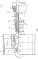
- FIG. 1 schematically illustrates a gas turbine engine 20.
- the gas turbine engine 20 is disclosed herein as a two-spool turbofan that generally incorporates a fan section 22, a compressor section 24, a combustor section 26 and a turbine section 28.
- Alternative engines might include other systems or features.
- the fan section 22 drives air along a bypass flow path B in a bypass duct, while the compressor section 24 drives air along a core flow path C for compression and communication into the combustor section 26 and then expansion through the turbine section 28.
- the exemplary gas turbine engine 20 generally includes a low speed spool 30 and a high speed spool 32 mounted for rotation about an engine central longitudinal axis A relative to an engine static structure 36 via several bearing systems 38. It should be understood that various bearing systems 38 at various locations may alternatively or additionally be provided, and the location of bearing systems 38 may be varied as appropriate to the application.
- the low speed spool 30 generally includes an inner shaft 40 that interconnects a fan 42, a low pressure compressor 44 and a low pressure turbine 46.
- the inner shaft 40 is connected to the fan 42 through a speed change mechanism, which in exemplary gas turbine engine 20 is illustrated as a geared architecture 48 to drive the fan 42 at a lower speed than the low speed spool 30.
- the high speed spool 32 includes an outer shaft 50 that interconnects a high pressure compressor 52 and high pressure turbine 54.
- a combustor 56 is arranged in the gas turbine engine 20 between the high pressure compressor 52 and the high pressure turbine 54.
- the engine static structure 36 is arranged generally between the high pressure turbine 54 and the low pressure turbine 46.
- the engine static structure 36 further supports the bearing systems 38 in the turbine section 28.
- the inner shaft 40 and the outer shaft 50 are concentric and rotate via bearing systems 38 about the engine central longitudinal axis A which is collinear with their longitudinal axes.
- the core airflow is compressed by the low pressure compressor 44 and then the high pressure compressor 52, is mixed and burned with fuel in the combustor 56 and is then expanded over the high pressure turbine 54 and the low pressure turbine 46.
- the high and low pressure turbines 54 and 46 rotationally drive the low speed spool 30 and the high speed spool 32, respectively, in response to the expansion.
- geared architecture 48 may be located aft of the combustor section 26 or even aft of the turbine section 28, and the fan section 22 may be positioned forward or aft of the location of geared architecture 48.
- An oil lubrication system can be provided that includes an oil pump, sometimes referred to as a main pump, and a network of conduits and nozzles to feed the bearings with oil.
- This oil is contained in bearing cavities, typically formed inside annular bearing chambers.
- a scavenge system having one or more scavenge lines extending from the bearing chambers and one or more scavenge pumps can be used to recover the oil, which can be in the form of an oil foam at that stage. Air/oil separation and filtering is typically provided for before returning the processed oil to the bearings.
- the oil flow pattern generally operates as follows: Oil particles coalesce along internal bearing chamber partitions and form a liquid partition film which contains air bubbles. In the radial space between the rotating shaft and the liquid oil film, a mixture of air and dispersed oil particles swirl in a circumferential direction at a velocity greater than the liquid oil film flow along the partitions. As a result, the oil film flow is exposed to high shear stresses at the air/oil film interface. Film thickness and velocity distributions inside the bearing are driven by the magnitude of that interfacial shear and superimposed effects of gravitational forces.
- air and oil flows are discharged to an oil scavenge system which communicates with the oil sump and which is partially formed within the bearing chamber.
- the bearing chamber can include a terminal block defining a keyway.
- the oil nozzle can be fit into the keyway.
- the oil nozzle can be bifurcated with a main nozzle section and an additional nozzle section that splits off from the main nozzle section.
- the main and additional nozzle sections each have an aperture with grooves or rifling. They can be directed in different directions (i.e., with different attitudes, altitudes, etc.). Additional bifurcations are possible to either the main section or the additional nozzle section.
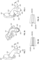
- an oil nozzle 201 is provided for use with a bearing chamber of the gas turbine engine 20 of FIG. 1 .
- the oil nozzle 201 can be additively manufactured and can be connected to or fit into an interior surface of the bearing chamber as will be described below.
- the oil nozzle 201 includes a main section 210 defining an internal channel 211, a main nozzle section 220 and an additional nozzle section 230.
- the main nozzle section 220 is coupled to the main section 210 and is formed to define a main nozzle internal channel 221 that is fluidly communicative with the internal channel 211 and an aperture 222 at a distal end thereof.
- a fluid such as oil for lubricating and cooling the bearing chamber, can be flown into the internal channel 211 and at least a portion of the fluid can be directed from the internal channel 211 to the main nozzle internal channel 221. From there, the fluid exits the main nozzle internal channel 221 via the aperture 222.
- the additional nozzle section 230 is split off from the main nozzle section 220 and is formed to define an additional nozzle internal channel 231 that is fluidly communicative with the main nozzle internal channel 221 and an aperture 232 at a distal end thereof. A remaining portion of the fluid can be directed from the main nozzle internl channel 221 to the additional nozzle internal channel 231 so as to exit from the additional nozzle internal channel 231 via the aperture 232.
- the additional nozzle section 230 can have a sharp turn 233 at a proximal end thereof neer the split.
- the main nozzle section 220 and the additional nozzle section 230 point in different directions with different attitudes, altitudes, etc., so that they each direct fluid toward different particular targets (i.e., sections of the bearing chamber which are particularly in need of cooling and lubrication).
- At least one of the main nozzle section 220 and the additional nozzle section 230 includes grooves 301 (see FIG. 3B ) or rifling 302 (see FIG. 3C ) at the corresponding aperture 222/232.
- This serves to increase control of the flow of the fluid exiting the aperture 222/232 and to thereby improve an ability of the at least one of the main nozzle section 220 and the additional nozzle section 230 to aim the fluid in the respective different directions.
- the apertures 222/232 need not have similar configurations and can, in certain cases, have differing aperture configurations from one another.
- FIGS. 2 and 3A generally illustrate a bifurcated oil nozzle
- the oil nozzle can be trifurcated or split into greater numbers of separate additional nozzles.
- the oil nozzle 201 can include another additional nozzle section 401 that is split off from the main nozzle section (see FIG. 4 ) and/or another additional nozzle section 501 which is split off from the additional nozzle section 230 (see FIG. 5 ).
- the another additional nozzle section 401/501 can be formed to include an interior channel and an aperture 402/502 generally as described above whereby fluid, such as the oil, can be flown though the interior channels and exited via the corresponding aperture 402/502 toward an additional target for cooling and lubrication.
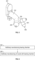
- a method 600 of manufacturing a bearing chamber such as the bearing chamber described above, is provided.
- the method 600 includes additively manufacturing the bearing chamber (block 601) and additively manufacturing one or more oil nozzles integrally with the bearing chamber (block 602) where the one or more oil nozzles are provided as the oil nozzle 201 described above.
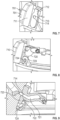
- a bearing chamber 701 is provided and includes an interior surface 710, which can be additively manufactured, and an oil nozzle 720, which can also be additively manufactured.
- the interior surface 710 includes a terminal block 711 that is formed to define a keyway 712 and a conduit 713.
- the conduit 713 extends through a body of the bearing chamber 701 and terminates at a terminus 714 at the keyway 712.
- the oil nozzle 720 is similar to the oil nozzle described above and like details need not be described again.
- the oil nozzle 720 is formed to define an internal channel 721 with an opening 722 (i.e., the internal channel 211 of FIG. 3A ) and includes a base 723.
- Both the keyway 712 and the base 723 can be elongate.
- the base 723 is tightly fittable in the keyway 712.
- the base 723 can also include a fastening point 724, at which the base 723 is fastened to the terminal block 711 at the keyway 712.
- the opening 722 of the internal channel 721 sits flush against the terminus 714 of the conduit 713 whereby the internal channel 721 is fluidly communicative with the conduit 713.
- oil or other fluids directed into and through the conduit 713 enter and flow through the internal channel 721.
- an orientation of the keyway 712 and a configuration of the oil nozzle 720 are cooperatively established to aim the oil nozzle 720 at one or more predefined targets within the bearing chamber 701. In this way, the orientation of the keyway 712 and the configuration of the oil nozzle 720 work cooperatively to aim a flow of oil or other fluids passing through the internal channel 721 toward the one or more predefined targets.
- a method of additively manufacturing a bearing chamber such as the bearing chamber 701 of FIGS. 7-9 , is provided.
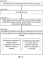
- the method includes additively manufacturing an interior surface of the bearing chamber to include a terminal block defining a keyway and a conduit terminating at the keyway (block 1001) and forming an oil nozzle defining an internal channel and including a base (block 1002).
- the method further includes tightly fitting the base in the keyway such that the internal channel is fluidly communicative with the conduit (block 1003) and establishing an orientation of the keyway and a configuration of the oil nozzle to aim the oil nozzle at one or more predefined targets within the bearing chamber (block 1004).
- the establishing of the orientation of the keyway can be set first and the configuration of the oil nozzle can be based on the orientating of the keyway or the establishing of the the configuration of the oil nozzle can be set first and the orientation of the keyway can be based on the configuration of the oil nozzle.
- the oil nozzle can be additively manufactured to be integral with a bearing chamber body and can be bifurcated with a main nozzle section and an additional nozzle section that splits off from the main nozzle section.
- the main and additional nozzle sections each have an aperture with grooves or rifling, they can be directed in different directions (i.e., with different attitudes, altitudes, etc.) and additional bifurcations are possible to either the main section or the additional nozzle section so as to provide for substantial oil coverage for lubrication and cooling.
Landscapes
- Engineering & Computer Science (AREA)
- General Engineering & Computer Science (AREA)
- Mechanical Engineering (AREA)
- Chemical & Material Sciences (AREA)
- Combustion & Propulsion (AREA)
- Oil, Petroleum & Natural Gas (AREA)
- Rolling Contact Bearings (AREA)
- Manufacturing & Machinery (AREA)
- Materials Engineering (AREA)
- Sliding-Contact Bearings (AREA)
Abstract
Description
- Exemplary embodiments of the present disclosure relate generally to gas turbine engines and, in one embodiment, to an oil nozzle for a bearing chamber of a gas turbine engine.
- In a gas turbine engine, air is compressed in a compressor and compressor air is then mixed with fuel and combusted in a combustor to produce a high-temperture and high-pressure working fluid. This working fluid is directed into a turbine in which the working fluid is expanded to generate power. The generated power drives the rotation of a rotor within the turbine through aerodynamic interactions between the working fluid and turbine blades or airfoils. The rotor can be used to drive rotations of a propeller or to produce electricity in a generator.
- Certain parts, such as a bearing chamber, in a gas turbine engine need a supply of oil for cooling. In conventional systems, this oil is supplied via individual, single-stream nozzles. A problem with the conventional individual, single-stream nozzles is that they are expensive and require significant numbers of additional parts for fastening each of the individual, single-stream nozzles in place.
- Accordingly, a need exists for improved oil distribution in a bearing chamber of a gas turbine engine.
- According to an aspect of the invention, a bearing chamber is provided. The bearing chamber includes an interior surface comprising a terminal block defining a keyway and a conduit terminating at the keyway and an oil nozzle defining an internal channel. The oil nozzle includes a base tightly fittable in the keyway. When the base is tightly fit in the keyway, the internal channel is communicative with the conduit and an orientation of the keyway and a configuration of the oil nozzle are cooperatively established to aim the oil nozzle at a predefined target within the bearing chamber.
- In an embodiment of the above, the interior surface and the terminal block are additively manufactured.
- In an embodiment of any of the above, the keyway and the base are each elongate.
- In an embodiment of any of the above, the base includes a fastening point at which the base is fastened to the terminal block at the keyway.
- In an embodiment of any of the above, an opening of the internal channel sits flush against a terminus of the conduit.
- In an embodiment of any of the above, the oil nozzle includes a main section defining the internal channel, a main nozzle section coupled to the main section and defining a main nozzle internal channel communicative with the internal channel and an aperture at a distal end thereof and an additional nozzle section split off from the main nozzle section and defining an additional nozzle internal channel communicative with the main nozzle internal channel and an aperture at a distal end thereof.
- In an embodiment of any of the above, the main nozzle section and the additional nozzle section point in different directions.
- In an embodiment of any of the above, at least one of the main nozzle section and the additional nozzle section includes grooves at the corresponding aperture.
- In an embodiment of any of the above, at least one of the main nozzle section and the additional nozzle section includes rifling at the corresponding aperture.
- In an embodiment of any of the above, the main nozzle section and the additional nozzle section have different aperture configurations.
- In an embodiment of any of the above, a proximal end of the additional nozzle section includes a sharp turn.
- In an embodiment of any of the above, another additional nozzle section is split off from the main nozzle section.
- In an embodiment of any of the above, another additional nozzle section is split off from the additional nozzle section.
- In an embodiment of any of the above, the oil nozzle includes a main section defining the internal channel, a main nozzle section coupled to the main section and defining a main nozzle internal channel communicative with the internal channel and an aperture at a distal end thereof and multiple additional nozzle sections, each of which is split off from the main nozzle section and each of which defines an additional nozzle internal channel communicative with the main nozzle internal channel and an aperture at a distal end thereof.
- In an embodiment of any of the above, the main nozzle section and each of the multiple additional nozzle sections point in different directions.
- In an embodiment of any of the above, the oil nozzle includes a main section defining the internal channel, a main nozzle section coupled to the main section and defining a main nozzle internal channel communicative with the internal channel and an aperture at a distal end thereof through, an additional nozzle section split off from the main nozzle section and another additional nozzle section split off from the additional nozzle section, each of the additional nozzle section and the another additional nozzle section defining an additional nozzle internal channel communicative with the main nozzle internal channel and an aperture at a distal end thereof.
- In an embodiment of any of the above, the main nozzle section, the additional nozzle section and the another additional nozzle section point in different directions.
- According to an aspect of the invention, a method of additively manufacturing a bearing chamber is provided. The method includes additively manufacturing an interior surface comprising a terminal block defining a keyway and a conduit terminating at the keyway, forming an oil nozzle defining an internal channel and comprising a base, tightly fitting the base in the keyway such that the internal channel is communicative with the conduit and establishing an orientation of the keyway and a configuration of the oil nozzle to aim the oil nozzle at a predefined target within the bearing chamber.
- In an embodiment of the above, the establishing of the orientation of the keyway is set first and the configuration of the oil nozzle is based on the orientating of the keyway.
- In an embodiment of any of the above, the establishing of the the configuration of the oil nozzle is set first and the orientation of the keyway is based on the configuration of the oil nozzle.
- These and other advantages and features will become more apparent from the following description taken in conjunction with the drawings.
- The following descriptions should not be considered limiting in any way. With reference to the accompanying drawings, like elements are numbered alike:
-
FIG. 1 is a partial cross-sectional view of a gas turbine engine; -
FIG. 2 is a perspective view of an oil nozzle for a bearing chamber of a gas turbine engine in accordance with embodiments; -
FIG. 3A is a cutaway perspective view of the oil nozzle ofFIG. 2 in accordance with embodiments; -
FIGS. 3B and 3C are enlarged side views of the portion ofFIG. 3A encircled by dashed line 3-3 in accordance with embodiments; -
FIG. 4 is a perspective view of an oil nozzle for a bearing chamber of a gas turbine engine in accordance with further embodiments; -
FIG. 5 is a perspective view of an oil nozzle for a bearing chamber of a gas turbine engine in accordance with further embodiments; -
FIG. 6 is a flow diagram illustrating a method of additively manufacturing a bearing chamber in accordance with embodiments; -
FIG. 7 is a perspective view of a bearing chamber and an interior surface of the bearing chamber with a terminal block in accordance with embodiments; -
FIG. 8 is a perspective view of the bearing chamber and the interior surface of the bearing chamber with the terminal block ofFIG. 7 and an oil nozzle in accordance with embodiments; -
FIG. 9 is a perspective view of the bearing chamber and the interior surface of the bearing chamber with the terminal block ofFIG. 7 and an inteiror of the oil nozzle ofFIG. 8 in accordance with embodiments; and -
FIG. 10 is a flow diagram illustrating a method of additively manufacturing a bearing chamber in accordance with embodiments. - These and other advantages and features will become more apparent from the following description taken in conjunction with the drawings.
- A detailed description of one or more embodiments of the disclosed apparatus and method are presented herein by way of exemplification and not limitation with reference to the Figures.
-
FIG. 1 schematically illustrates agas turbine engine 20. Thegas turbine engine 20 is disclosed herein as a two-spool turbofan that generally incorporates afan section 22, acompressor section 24, acombustor section 26 and aturbine section 28. Alternative engines might include other systems or features. Thefan section 22 drives air along a bypass flow path B in a bypass duct, while thecompressor section 24 drives air along a core flow path C for compression and communication into thecombustor section 26 and then expansion through theturbine section 28. Although depicted as a two-spool turbofan gas turbine engine in the disclosed non-limiting embodiment, it should be understood that the concepts described herein are not limited to use with two-spool turbofans as the teachings may be applied to other types of turbine engines including three-spool architectures. - The exemplary
gas turbine engine 20 generally includes alow speed spool 30 and ahigh speed spool 32 mounted for rotation about an engine central longitudinal axis A relative to an enginestatic structure 36 viaseveral bearing systems 38. It should be understood thatvarious bearing systems 38 at various locations may alternatively or additionally be provided, and the location ofbearing systems 38 may be varied as appropriate to the application. - The
low speed spool 30 generally includes aninner shaft 40 that interconnects afan 42, alow pressure compressor 44 and alow pressure turbine 46. Theinner shaft 40 is connected to thefan 42 through a speed change mechanism, which in exemplarygas turbine engine 20 is illustrated as a gearedarchitecture 48 to drive thefan 42 at a lower speed than thelow speed spool 30. Thehigh speed spool 32 includes anouter shaft 50 that interconnects ahigh pressure compressor 52 andhigh pressure turbine 54. Acombustor 56 is arranged in thegas turbine engine 20 between thehigh pressure compressor 52 and thehigh pressure turbine 54. The enginestatic structure 36 is arranged generally between thehigh pressure turbine 54 and thelow pressure turbine 46. The enginestatic structure 36 further supports the bearingsystems 38 in theturbine section 28. Theinner shaft 40 and theouter shaft 50 are concentric and rotate via bearingsystems 38 about the engine central longitudinal axis A which is collinear with their longitudinal axes. - The core airflow is compressed by the
low pressure compressor 44 and then thehigh pressure compressor 52, is mixed and burned with fuel in thecombustor 56 and is then expanded over thehigh pressure turbine 54 and thelow pressure turbine 46. The high andlow pressure turbines low speed spool 30 and thehigh speed spool 32, respectively, in response to the expansion. It will be appreciated that each of the positions of thefan section 22,compressor section 24,combustor section 26,turbine section 28, and fandrive gear system 48 may be varied. For example, gearedarchitecture 48 may be located aft of thecombustor section 26 or even aft of theturbine section 28, and thefan section 22 may be positioned forward or aft of the location of gearedarchitecture 48. - Within the
gas turbine engine 20, bearings are used to provide smooth relative rotation between the various shafts and non-rotating components and/or between two shafts which rotate at different speeds. An oil lubrication system can be provided that includes an oil pump, sometimes referred to as a main pump, and a network of conduits and nozzles to feed the bearings with oil. This oil is contained in bearing cavities, typically formed inside annular bearing chambers. A scavenge system having one or more scavenge lines extending from the bearing chambers and one or more scavenge pumps can be used to recover the oil, which can be in the form of an oil foam at that stage. Air/oil separation and filtering is typically provided for before returning the processed oil to the bearings. - In the bearing chambers, air and oil flows mix and generate a flow pattern about the engine central longitudinal axis A. The oil flow pattern generally operates as follows: Oil particles coalesce along internal bearing chamber partitions and form a liquid partition film which contains air bubbles. In the radial space between the rotating shaft and the liquid oil film, a mixture of air and dispersed oil particles swirl in a circumferential direction at a velocity greater than the liquid oil film flow along the partitions. As a result, the oil film flow is exposed to high shear stresses at the air/oil film interface. Film thickness and velocity distributions inside the bearing are driven by the magnitude of that interfacial shear and superimposed effects of gravitational forces.
- To achieve bearing chamber functionality, air and oil flows are discharged to an oil scavenge system which communicates with the oil sump and which is partially formed within the bearing chamber.
- As will be described below, a bearing chamber and an oil nozzle of the
gas turbine engine 20 ofFIG. 1 are provided. The bearing chamber can include a terminal block defining a keyway. The oil nozzle can be fit into the keyway. The oil nozzle can be bifurcated with a main nozzle section and an additional nozzle section that splits off from the main nozzle section. The main and additional nozzle sections each have an aperture with grooves or rifling. They can be directed in different directions (i.e., with different attitudes, altitudes, etc.). Additional bifurcations are possible to either the main section or the additional nozzle section. - With continued reference to
FIG. 1 and with additional reference toFIG. 2 and FIGS. 3A, 3B and 3C , anoil nozzle 201 is provided for use with a bearing chamber of thegas turbine engine 20 ofFIG. 1 . Theoil nozzle 201 can be additively manufactured and can be connected to or fit into an interior surface of the bearing chamber as will be described below. - In any case, the
oil nozzle 201 includes amain section 210 defining aninternal channel 211, amain nozzle section 220 and anadditional nozzle section 230. Themain nozzle section 220 is coupled to themain section 210 and is formed to define a main nozzleinternal channel 221 that is fluidly communicative with theinternal channel 211 and anaperture 222 at a distal end thereof. A fluid, such as oil for lubricating and cooling the bearing chamber, can be flown into theinternal channel 211 and at least a portion of the fluid can be directed from theinternal channel 211 to the main nozzleinternal channel 221. From there, the fluid exits the main nozzleinternal channel 221 via theaperture 222. Theadditional nozzle section 230 is split off from themain nozzle section 220 and is formed to define an additional nozzleinternal channel 231 that is fluidly communicative with the main nozzleinternal channel 221 and anaperture 232 at a distal end thereof. A remaining portion of the fluid can be directed from the mainnozzle internl channel 221 to the additional nozzleinternal channel 231 so as to exit from the additional nozzleinternal channel 231 via theaperture 232. In accordance with embodiments, theadditional nozzle section 230 can have asharp turn 233 at a proximal end thereof neer the split. - As shown in
FIG. 2 , themain nozzle section 220 and theadditional nozzle section 230 point in different directions with different attitudes, altitudes, etc., so that they each direct fluid toward different particular targets (i.e., sections of the bearing chamber which are particularly in need of cooling and lubrication). - As shown in
FIGS. 3B and 3C , at least one of themain nozzle section 220 and theadditional nozzle section 230 includes grooves 301 (seeFIG. 3B ) or rifling 302 (seeFIG. 3C ) at thecorresponding aperture 222/232. This serves to increase control of the flow of the fluid exiting theaperture 222/232 and to thereby improve an ability of the at least one of themain nozzle section 220 and theadditional nozzle section 230 to aim the fluid in the respective different directions. In accordance with further embodiments, it is to be understood that theapertures 222/232 need not have similar configurations and can, in certain cases, have differing aperture configurations from one another. - While
FIGS. 2 and 3A generally illustrate a bifurcated oil nozzle, it is to be understood with reference toFIGS. 4 and5 that the oil nozzle can be trifurcated or split into greater numbers of separate additional nozzles. For example, as shown inFIGS. 4 and5 , theoil nozzle 201 can include anotheradditional nozzle section 401 that is split off from the main nozzle section (seeFIG. 4 ) and/or anotheradditional nozzle section 501 which is split off from the additional nozzle section 230 (seeFIG. 5 ). In each of these cases, the anotheradditional nozzle section 401/501 can be formed to include an interior channel and anaperture 402/502 generally as described above whereby fluid, such as the oil, can be flown though the interior channels and exited via the correspondingaperture 402/502 toward an additional target for cooling and lubrication. - With reference to
FIG. 6 , a method 600 of manufacturing a bearing chamber, such as the bearing chamber described above, is provided. The method 600 includes additively manufacturing the bearing chamber (block 601) and additively manufacturing one or more oil nozzles integrally with the bearing chamber (block 602) where the one or more oil nozzles are provided as theoil nozzle 201 described above. - With reference to
FIGS. 7-9 , a bearingchamber 701 is provided and includes aninterior surface 710, which can be additively manufactured, and anoil nozzle 720, which can also be additively manufactured. Theinterior surface 710 includes aterminal block 711 that is formed to define akeyway 712 and aconduit 713. Theconduit 713 extends through a body of the bearingchamber 701 and terminates at aterminus 714 at thekeyway 712. Theoil nozzle 720 is similar to the oil nozzle described above and like details need not be described again. Theoil nozzle 720 is formed to define aninternal channel 721 with an opening 722 (i.e., theinternal channel 211 ofFIG. 3A ) and includes abase 723. Both thekeyway 712 and the base 723 can be elongate. In any case, thebase 723 is tightly fittable in thekeyway 712. The base 723 can also include afastening point 724, at which thebase 723 is fastened to theterminal block 711 at thekeyway 712. - When the
base 723 is tightly fit in thekeyway 712 as shown inFIGS. 8 and 9 , theopening 722 of theinternal channel 721 sits flush against theterminus 714 of theconduit 713 whereby theinternal channel 721 is fluidly communicative with theconduit 713. As such, oil or other fluids directed into and through theconduit 713 enter and flow through theinternal channel 721. In addition, when thebase 722 is tightly fit in thekeyway 712, an orientation of thekeyway 712 and a configuration of theoil nozzle 720 are cooperatively established to aim theoil nozzle 720 at one or more predefined targets within the bearingchamber 701. In this way, the orientation of thekeyway 712 and the configuration of theoil nozzle 720 work cooperatively to aim a flow of oil or other fluids passing through theinternal channel 721 toward the one or more predefined targets. - With reference to
FIG. 10 , a method of additively manufacturing a bearing chamber, such as the bearingchamber 701 ofFIGS. 7-9 , is provided. The method includes additively manufacturing an interior surface of the bearing chamber to include a terminal block defining a keyway and a conduit terminating at the keyway (block 1001) and forming an oil nozzle defining an internal channel and including a base (block 1002). The method further includes tightly fitting the base in the keyway such that the internal channel is fluidly communicative with the conduit (block 1003) and establishing an orientation of the keyway and a configuration of the oil nozzle to aim the oil nozzle at one or more predefined targets within the bearing chamber (block 1004). - In accordance with embodiments, in
block 1004, the establishing of the orientation of the keyway can be set first and the configuration of the oil nozzle can be based on the orientating of the keyway or the establishing of the the configuration of the oil nozzle can be set first and the orientation of the keyway can be based on the configuration of the oil nozzle. - Benefits of the features described herein are the provision of an oil nozzle of a gas turbine engine. The oil nozzle can be additively manufactured to be integral with a bearing chamber body and can be bifurcated with a main nozzle section and an additional nozzle section that splits off from the main nozzle section. The main and additional nozzle sections each have an aperture with grooves or rifling, they can be directed in different directions (i.e., with different attitudes, altitudes, etc.) and additional bifurcations are possible to either the main section or the additional nozzle section so as to provide for substantial oil coverage for lubrication and cooling.
- The term "about" is intended to include the degree of error associated with measurement of the particular quantity based upon the equipment available at the time of filing the application.
- The terminology used herein is for the purpose of describing particular embodiments only and is not intended to be limiting of the present disclosure. As used herein, the singular forms "a", "an" and "the" are intended to include the plural forms as well, unless the context clearly indicates otherwise. It will be further understood that the terms "comprises" and/or "comprising," when used in this specification, specify the presence of stated features, integers, steps, operations, elements, and/or components, but do not preclude the presence or addition of one or more other features, integers, steps, operations, element components, and/or groups thereof.
- While the present disclosure has been described with reference to an exemplary embodiment or embodiments, it will be understood by those skilled in the art that various changes may be made and equivalents may be substituted for elements thereof without departing from the scope of the present disclosure. In addition, many modifications may be made to adapt a particular situation or material to the teachings of the present disclosure without departing from the essential scope thereof. Therefore, it is intended that the present disclosure not be limited to the particular embodiment disclosed as the best mode contemplated for carrying out this present disclosure, but that the present disclosure will include all embodiments falling within the scope of the claims.
Claims (15)
- A bearing chamber (701), comprising:an interior surface (710) comprising a terminal block (711) defining a keyway (712) and a conduit (713) terminating at the keyway (712); andan oil nozzle (201; 720) defining an internal channel (211; 721) and comprising a base (723) tightly fittable in the keyway (712), wherein, when the base (723) is tightly fit in the keyway (712):the internal channel (211; 721) is communicative with the conduit (713), andan orientation of the keyway (712) and a configuration of the oil nozzle (201; 720) are cooperatively established to aim the oil nozzle (201; 720) at a predefined target within the bearing chamber (701).
- The bearing chamber (701) according to claim 1, wherein the interior surface (710) and the terminal block (711) are additively manufactured.
- The bearing chamber (701) according to any preceding claim, wherein the keyway (712) and the base (723) are each elongate.
- The bearing chamber (701) according to any preceding claim, wherein the base (723) comprises a fastening point (724) at which the base (723) is fastened to the terminal block (711) at the keyway (712).
- The bearing chamber (701) according to any preceding claim, wherein an opening (722) of the internal channel (211; 721) sits flush against a terminus (714) of the conduit (713).
- The bearing chamber (701) according to any preceding claim, wherein the oil nozzle (201; 720) comprises:a main section (210) defining the internal channel (211; 721);a main nozzle section (220) coupled to the main section (210) and defining a main nozzle internal channel (221) communicative with the internal channel (211; 721) and an aperture (222) at a distal end thereof; andan additional nozzle section (230) split off from the main nozzle section (220) and defining an additional nozzle internal channel (231) communicative with the main nozzle internal channel (221) and an aperture (232) at a distal end thereof,optionally wherein the main nozzle section (220) and the additional nozzle section (230) have different aperture configurations.
- The bearing chamber (701) according to claim 6, wherein the main nozzle section (220) and the additional nozzle section (230) point in different directions.
- The bearing chamber (701) according to claim 6 or 7, wherein the main nozzle section (220) and/or the additional nozzle section (230) comprises grooves (301) or rifling (302), at the corresponding aperture (222, 232).
- The bearing chamber (701) according to any of claims 6 to 8, wherein a proximal end of the additional nozzle section (230) comprises a sharp turn (233).
- The bearing chamber (701) according to any of claims 6 to 9, further comprising another additional nozzle section (401) which is split off from the main nozzle section (220).
- The bearing chamber (701) according to any of claims 6 to 10, further comprising another additional nozzle section (501) which is split off from the additional nozzle section (230).
- The bearing chamber (701) according to any of claims 1 to 5, wherein the oil nozzle (201; 720) comprises:a main section (210) defining the internal channel (211; 721); anda main nozzle section (220) coupled to the main section (210) and defining a main nozzle internal channel (221) communicative with the internal channel (211; 721) and an aperture (222) at a distal end thereof, the oil nozzle optionally further comprising either:multiple additional nozzle sections (230; 401; 501), each of which is split off from the main nozzle section (220) and each of which defines an additional nozzle internal channel (231) communicative with the main nozzle internal channel (221) and an aperture (222; 232; 402; 502) at a distal end thereof, optionally wherein the main nozzle section (220) and each of the multiple additional nozzle sections point in different directions; oran additional nozzle section (230) split off from the main nozzle section (220), and another additional nozzle section (401; 501) split off from the additional nozzle section (230), each of the additional nozzle section (230) and the another additional nozzle section (401; 501) defining an additional nozzle internal channel (231) communicative with the main nozzle internal channel (221) and an aperture (232, 402; 502) at a distal end thereof, and optionally wherein the main nozzle section (220), the additional nozzle section (230) and the another additional nozzle section (401; 501) point in different directions.
- A method of additively manufacturing a bearing chamber (701), the method comprising:additively manufacturing an interior surface (710) comprising a terminal block (711) defining a keyway (712) and a conduit (713) terminating at the keyway (712);forming an oil nozzle (201; 720) defining an internal channel (211; 721) and comprising a base (723);tightly fitting the base (723) in the keyway (712) such that the internal channel (211; 721) is communicative with the conduit (713); andestablishing an orientation of the keyway (712) and a configuration of the oil nozzle (201; 720) to aim the oil nozzle (201; 720) at a predefined target within the bearing chamber (701).
- The method according to claim 13, wherein the establishing of the orientation of the keyway (712) is set first and the configuration of the oil nozzle (201; 720) is based on the orientating of the keyway (712).
- The method according to claim 13, wherein the establishing of the the configuration of the oil nozzle (201; 720) is set first and the orientation of the keyway (712) is based on the configuration of the oil nozzle (201; 720).
Applications Claiming Priority (1)
| Application Number | Priority Date | Filing Date | Title |
|---|---|---|---|
| US202263420045P | 2022-10-27 | 2022-10-27 |
Publications (1)
| Publication Number | Publication Date |
|---|---|
| EP4361408A1 true EP4361408A1 (en) | 2024-05-01 |
Family
ID=88558419
Family Applications (1)
| Application Number | Title | Priority Date | Filing Date |
|---|---|---|---|
| EP23206248.9A Pending EP4361408A1 (en) | 2022-10-27 | 2023-10-26 | Oil nozzle for bearing chamber |
Country Status (2)
| Country | Link |
|---|---|
| US (1) | US12571330B2 (en) |
| EP (1) | EP4361408A1 (en) |
Citations (3)
| Publication number | Priority date | Publication date | Assignee | Title |
|---|---|---|---|---|
| US20080083227A1 (en) * | 2006-10-06 | 2008-04-10 | Andreas Eleftheriou | Oil distributing unit |
| EP3254764A1 (en) * | 2016-06-07 | 2017-12-13 | United Technologies Corporation | Nozzle for delivering fluid to a component |
| EP3904644A2 (en) * | 2020-04-27 | 2021-11-03 | Raytheon Technologies Corporation | Fluid delivery system for rotational equipment |
Family Cites Families (5)
| Publication number | Priority date | Publication date | Assignee | Title |
|---|---|---|---|---|
| US2964248A (en) | 1955-11-18 | 1960-12-13 | Spraying Systems Co | Plural orifice fan shaped spray nozzle |
| US7063049B2 (en) * | 2004-03-03 | 2006-06-20 | Deere & Company | Directed spray jet and installation tool |
| US8074901B2 (en) * | 2005-12-01 | 2011-12-13 | Uniwave, Inc. | Lubricator nozzle and emitter element |
| US11230946B2 (en) | 2019-02-07 | 2022-01-25 | Raytheon Technologies Corporation | Non-uniform spray pattern oil delivery nozzle |
| US20220389872A1 (en) * | 2020-07-23 | 2022-12-08 | Sierra Turbines Inc. | Additively manufactured gas turbine fuel injector ring and uni-body turbine engine |
-
2023
- 2023-10-24 US US18/493,479 patent/US12571330B2/en active Active
- 2023-10-26 EP EP23206248.9A patent/EP4361408A1/en active Pending
Patent Citations (3)
| Publication number | Priority date | Publication date | Assignee | Title |
|---|---|---|---|---|
| US20080083227A1 (en) * | 2006-10-06 | 2008-04-10 | Andreas Eleftheriou | Oil distributing unit |
| EP3254764A1 (en) * | 2016-06-07 | 2017-12-13 | United Technologies Corporation | Nozzle for delivering fluid to a component |
| EP3904644A2 (en) * | 2020-04-27 | 2021-11-03 | Raytheon Technologies Corporation | Fluid delivery system for rotational equipment |
Also Published As
| Publication number | Publication date |
|---|---|
| US20240141803A1 (en) | 2024-05-02 |
| US12571330B2 (en) | 2026-03-10 |
Similar Documents
| Publication | Publication Date | Title |
|---|---|---|
| EP2855882B1 (en) | Lubrication arrangement for a gas turbine engine gear assembly | |
| US7296398B2 (en) | Counter-rotating turbine engine and method of assembling same | |
| EP2959129B1 (en) | Auxiliary lubricant supply pump stage integral with main lubricant pump stage | |
| EP3004568B1 (en) | Gas turbine engine with dove-tailed tobi vane | |
| EP3693651B1 (en) | Non-uniform spray pattern oil delivery nozzle | |
| EP2949883A1 (en) | Gas turbine engine lubrication system | |
| EP3084180B1 (en) | Transfer bearing for geared turbofan | |
| EP3772571B1 (en) | Ducted oil scoop for gas turbine engine | |
| EP3543511B1 (en) | Power takeoff transmission | |
| CN112443652B (en) | Gear assembly for an aircraft engine with a collector | |
| EP3708794A1 (en) | Dual radial scoop oil delivery system | |
| EP4361408A1 (en) | Oil nozzle for bearing chamber | |
| EP3677754A1 (en) | Generator and rotary union with non-contact interface | |
| EP4365415A1 (en) | Annular oil distributor for bearing chamber | |
| EP4074952B1 (en) | Geared gas turbine with oil scavenge ejector pump assist | |
| US20220389820A1 (en) | Anti-vortex tube retaining ring and bore basket | |
| EP3933170B1 (en) | Mid mount sleeve arrangement | |
| US20180094543A1 (en) | Insert apparatus and system for oil nozzle boundary layer injection | |
| EP4365416A1 (en) | Bearing chamber with thermal heat exchange fins | |
| EP4365417A1 (en) | Bearing chamber with mapped thermal heat exchange fins | |
| EP4365412A1 (en) | Oil passage built into bearing compartment spring | |
| EP3663542B1 (en) | Oil supply arrangement for bearing | |
| EP3789586A1 (en) | Aerodynamic element assembly for a gas turbine engine |
Legal Events
| Date | Code | Title | Description |
|---|---|---|---|
| PUAI | Public reference made under article 153(3) epc to a published international application that has entered the european phase |
Free format text: ORIGINAL CODE: 0009012 |
|
| STAA | Information on the status of an ep patent application or granted ep patent |
Free format text: STATUS: THE APPLICATION HAS BEEN PUBLISHED |
|
| AK | Designated contracting states |
Kind code of ref document: A1 Designated state(s): AL AT BE BG CH CY CZ DE DK EE ES FI FR GB GR HR HU IE IS IT LI LT LU LV MC ME MK MT NL NO PL PT RO RS SE SI SK SM TR |
|
| STAA | Information on the status of an ep patent application or granted ep patent |
Free format text: STATUS: REQUEST FOR EXAMINATION WAS MADE |
|
| 17P | Request for examination filed |
Effective date: 20241030 |
|
| RBV | Designated contracting states (corrected) |
Designated state(s): AL AT BE BG CH CY CZ DE DK EE ES FI FR GB GR HR HU IE IS IT LI LT LU LV MC ME MK MT NL NO PL PT RO RS SE SI SK SM TR |
|
| STAA | Information on the status of an ep patent application or granted ep patent |
Free format text: STATUS: EXAMINATION IS IN PROGRESS |
|
| 17Q | First examination report despatched |
Effective date: 20250903 |