EP4361358A1 - Work machine information collection system - Google Patents
Work machine information collection system Download PDFInfo
- Publication number
- EP4361358A1 EP4361358A1 EP22828036.8A EP22828036A EP4361358A1 EP 4361358 A1 EP4361358 A1 EP 4361358A1 EP 22828036 A EP22828036 A EP 22828036A EP 4361358 A1 EP4361358 A1 EP 4361358A1
- Authority
- EP
- European Patent Office
- Prior art keywords
- operation data
- unit
- work machine
- determination
- data
- Prior art date
- Legal status (The legal status is an assumption and is not a legal conclusion. Google has not performed a legal analysis and makes no representation as to the accuracy of the status listed.)
- Pending
Links
Images






Classifications
-
- E—FIXED CONSTRUCTIONS
- E02—HYDRAULIC ENGINEERING; FOUNDATIONS; SOIL SHIFTING
- E02F—DREDGING; SOIL-SHIFTING
- E02F9/00—Component parts of dredgers or soil-shifting machines, not restricted to one of the kinds covered by groups E02F3/00 - E02F7/00
- E02F9/26—Indicating devices
- E02F9/267—Diagnosing or detecting failure of vehicles
-
- E—FIXED CONSTRUCTIONS
- E02—HYDRAULIC ENGINEERING; FOUNDATIONS; SOIL SHIFTING
- E02F—DREDGING; SOIL-SHIFTING
- E02F9/00—Component parts of dredgers or soil-shifting machines, not restricted to one of the kinds covered by groups E02F3/00 - E02F7/00
- E02F9/24—Safety devices, e.g. for preventing overload
-
- E—FIXED CONSTRUCTIONS
- E02—HYDRAULIC ENGINEERING; FOUNDATIONS; SOIL SHIFTING
- E02F—DREDGING; SOIL-SHIFTING
- E02F9/00—Component parts of dredgers or soil-shifting machines, not restricted to one of the kinds covered by groups E02F3/00 - E02F7/00
- E02F9/20—Drives; Control devices
- E02F9/2025—Particular purposes of control systems not otherwise provided for
- E02F9/2054—Fleet management
Definitions
- the present invention relates to a work machine information collection system.
- Patent Literature 1 JP 2014-25343 A
- Patent Literature 1 when a large amount of data is transmitted from the work machine side to the server, communication traffic increases and a load is also applied to the communication device of the work machine.
- an object of the present invention is to reduce communication traffic related to information collection when diagnosing a work machine.
- a work machine information collection system in which a work machine having an operation unit and a server are communicably connected to each other, wherein the work machine includes: an operation data output unit that outputs an operation data corresponding to an operation state of the operation unit; a determination unit that determines whether not the operation data satisfies a determination condition for determining whether or not to transmit the operation data output by the operation data output unit to the server; and a first communication unit that transmits the operation data to the server when the determination unit determines that the operation data satisfies the determination condition.
- the server includes: a collection determination unit that determines a collection data, which is an operation data to be collected for diagnosis of the work machine, based on the operation data transmitted from the first communication unit; and a second communication unit that transmits a request signal for requesting transmission of the collection data determined by the collection determination unit to the work machine, and the first communication unit transmits the collection data corresponding to the request signal to the server when the request signal is received.
- a collection determination unit that determines a collection data, which is an operation data to be collected for diagnosis of the work machine, based on the operation data transmitted from the first communication unit
- a second communication unit that transmits a request signal for requesting transmission of the collection data determined by the collection determination unit to the work machine, and the first communication unit transmits the collection data corresponding to the request signal to the server when the request signal is received.
- the server includes a diagnosis unit that diagnoses a state of the operation unit based on the collection data.
- the work machine includes: a first determination unit that determines whether or not the operation data satisfies a first determination condition for determining whether or not to issue a warning; and a warning unit that issues a warning when the first determination unit determines that the operation data satisfies the first determination condition, the determination unit is a second determination unit, the determination condition is a second determination condition, the first determination condition includes a first threshold value for determining a state of a signal included in the operation data, and the second determination condition includes a second threshold value that is for determining a state of a signal included in the operation data and is higher than the first threshold value.
- the work machine includes: a first determination unit that determines whether or not the operation data satisfies a first determination condition for determining whether or not to issue a warning; and a warning unit that issues a warning when the first determination unit determines that the operation data satisfies the first determination condition, the determination unit is a second determination unit, the determination condition is a second determination condition, the first determination condition includes a first threshold value for determining a state of a signal included in the operation data, and the second determination condition includes a second threshold value that is for determining a state of a signal included in the operation data and is lower than the first threshold value.
- the present system is used for diagnosing a failure in a work machine which is a backhoe, for example. First, the present system will be described together with the configuration of the work machine.
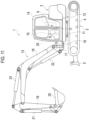
- Fig. 11 shows an example of the work machine.
- a work machine (backhoe) 1 includes a traveling device 2 at a lower portion and a revolving body 3 at an upper portion.
- the traveling device 2 adopts a crawler type traveling device which includes a pair of left and right traveling bodies 4 each having a rubber cover band and is configured in a manner that both of the traveling bodies 4 are driven by a traveling motor M.
- a dozer 5 is provided at a front portion of the traveling device 2.
- the revolving body 3 includes a revolving base 12 supported on the traveling device 2 via a revolving bearing 11 in a manner of being capable of revolving left and right around a revolving axis in an up-down direction, and a working device 13 (excavating device) provided at a front portion of the revolving base 12.
- An engine, a radiator, a driving seat 9, a fuel tank, a hydraulic oil tank, and the like are provided on the revolving base 12.
- a display device 25 for displaying various information related to the work machine 1 is provided around the driving seat 9.
- the driving seat 9 is surrounded by a cabin 14 provided on the revolving base 12.
- the working device 13 includes a swing bracket 17 that is supported by a support bracket 16 which is provided and offset slightly to the right from a central portion in a left-right direction at a front portion of the revolving base 12 in a manner of being capable of swinging horizontally around an axis in the up-down direction, a boom 18 that is pivotally attached to the swing bracket 17 at its base side in a manner of being capable of rotating around an axis in the left-right direction and is supported in a manner of being capable of swinging vertically, an arm 19 that is pivotally attached to a distal end of the boom 18 in a manner of being capable of rotating about an axis in the left-right direction and is supported in a manner of being capable of swinging back and forth, and a bucket 20 that is provided at a distal end of the arm 19 in a manner of being capable of performing a shoveling and dumping operation.
- the swing bracket 17 is swung by extension and contraction of a swing cylinder provided in the revolving base 12, the boom 18 is swung by extension and contraction of a boom cylinder 22 interposed between the boom 18 and the swing bracket 17, the arm 19 is swung by extension and contraction of an arm cylinder 23 interposed between the arm 19 and the boom 18, and the bucket 20 is shoveled and dumped by extension and contraction of a bucket cylinder 21 interposed between the bucket 20 and the arm 19.
- Fig. 10 is a block diagram showing a configuration of the work machine.
- the work machine 1 includes a control device 100.
- the control device 100 performs various controls of the work machine.
- the control device 100 outputs a control signal to a control valve 90 that operates hydraulic actuators such as the bucket cylinder 21, the boom cylinder 22, and the arm cylinder 23, for example, a 3-position switching electromagnetic valve, thereby switching the control valve 90 to actuate the hydraulic actuators.
- the control device 100 outputs a control signal to a work lamp 91 to perform illumination control such as turning on, blinking, and turning off the work lamp 91.
- a plurality of sensors 101 to 106 are connected to the control device 100.
- the sensor 101 measures a pressure of a hydraulic oil discharged from a hydraulic pump P1, that is, an output of the hydraulic pump P1.
- the sensor 102 measures an output of a prime mover 92, that is, the rotation speed of the prime mover 92.
- the sensor 103 measures a temperature of the hydraulic oil (oil temperature).
- the sensor 104 measures an amount of lubricant oil in bearings, gears, etc.
- the sensor 105 is provided in the vicinity of the bearing or in a housing or the like that supports the bearing, and measures an acceleration or the like of the bearing.
- the sensor 106 measures a voltage of a storage battery such as a battery, that is, an energy storage capacity.
- Fig. 1 shows an overall view of a work machine information collection system.
- the work machine information collection system includes a data collection device 30 and a server 40.
- the data collection device 30 is mounted on the work machine 1 to collect operation data when an operation unit of the work machine 1 operates and transmit the collected operation data to the server 40, or receive data transmitted from the server 40.
- various devices and the like are mounted on the work machine 1, and all the devices that operate are referred to as operation unit.
- the operation unit includes, for example, the work lamp 91, the hydraulic pump P1, the prime mover 92, the bearing, the hydraulic actuator, the control valve 90, the battery, and the like.
- the above-described operation unit is merely an example and is not limited thereto.
- the operation data corresponding to the operation state of the operation unit is data indicating physical quantities of the operation unit. Examples of the data include a value indicating vibrations generated in the operation unit, a value indicating sound emitted by the operation unit, a current value flowing through a predetermined portion of the operation unit, and a voltage.
- Data other than the data indicating physical quantities is also the operation data.
- data indicating a temperature of the hydraulic oil, an integrated operation time (hour meter) of the work machine 1, and a water temperature is also the operation data.
- the operation data may include sales management data such as a sales company that has sold the work machine, a name of a customer who owns the work machine, a contact address of the customer, presence or absence of a maintenance contract, and a person in charge.
- the data collection device 30 transmits operation data to be collected, that is, collection data to the server 40 in response to a request from the server 40 side.
- the server 40 stores various data related to maintenance and inspection, etc. of the work machine 1 and processes the data.
- the server 40 requests data from the data collection device 30 and receives data transmitted from the data collection device 30. In this way, in the work machine information collection system, various types of data are exchanged between the data collection device 30 and the server 40, and thereby, management such as maintenance and inspection, etc. of the work machine 1 can be performed.
- Fig. 2 shows a block diagram of the work machine information collection system.
- the data collection device 30 is mounted on the work machine 1 and connected to an in-vehicle network provided in the work machine 1.
- the in-vehicle network is, for example, CAN, LIN, FlexRay, or the like, and various signals (data) at the time when the work machine 1 operates flow through the in-vehicle network.
- the data collection device 30 collects various data flowing through the in-vehicle network and stores the collected data.
- the data collection device 30 includes an operation data output unit 31, a first determination unit 32, a second determination unit 33 (determination unit), and a first communication unit 34.
- the operation data output unit 31 outputs operation data corresponding to the operation state of the operation unit. For example, the operation data output unit 31 outputs the operation data corresponding to the operation state of the hydraulic pump P1 based on the output result of the sensor 101 during the operation of the hydraulic pump P1. In addition, for example, the operation data output unit 31 outputs operation data corresponding to the operation state of the bearing based on the output of the sensor 105 during traveling of the work machine 1. In addition, for example, when a switch for lighting the work lamp 91 is turned on, operation data corresponding to an operation state of the work lamp 91 is output based on a control signal output from the control device 100 to the work lamp 91.
- the first determination unit 32 determines whether or not the operation data at the time when the operation unit operates satisfies a first determination condition for determining whether or not to issue a warning.
- the warning here is performed, for example, by turning on an unillustrated warning lamp which is provided at the driving seat of the work machine 1 or sounding an alarm.
- the first determination condition can be set using a first threshold value, and for example, when a physical quantity included in the operation data becomes equal to or less than the first threshold value (or becomes equal to or more than the first threshold value), a warning may be issued.
- the second determination unit 33 determines whether or not the operation data satisfies a determination condition (second determination condition) for determining whether or not to transmit the operation data output by the operation data output unit 31 to the server 40.
- the second determination condition can be set using a second threshold value which is less strict than the first threshold value used to determine whether or not to issue a warning.
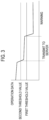
- Figs. 3 and 4 are explanatory diagrams showing an example of threshold value determination.
- a warning is issued when the physical quantity included in the operation data becomes equal to or less than the first threshold value
- a warning is issued when the physical quantity included in the operation data becomes equal to or more than the first threshold value
- the second determination condition is a condition for determining whether or not the physical quantity included in the operation data has reached the value corresponding to the warning, and is a condition based on the second threshold value which is less strict than the first determination condition (first threshold value) for determining whether or not the warning is to be generated.
- the second determination condition is a condition for grasping that the physical quantity included in the operation data is approaching the first determination condition corresponding to the warning.
- the second determination condition is set to ⁇ 20% (less than the first threshold value ⁇ 80% (0.8) of the first threshold value, more than the first threshold value ⁇ 1200 (1.2) of the first threshold value based on the first determination condition (first threshold value).
- the above-described second threshold value is an example and is not limited thereto.
- the first communication unit 34 performs radio communication with the server 40 and is configured by a communication device.
- the second determination unit 33 determines that the physical quantity included in the operation data satisfies the second determination condition (second threshold value), that is, when the physical quantity included in the operation data is approaching the first determination condition (first threshold value) corresponding to the warning
- the first communication unit 34 transmits the operation data (first operation data) to the server 40.
- the first communication unit 34 receives a request signal to be described later from the server 40
- the first communication unit 34 transmits the collection data (second operation data) corresponding to the request signal to the server 40.
- the threshold values (the first threshold value, the second threshold value) may be different for each operation unit.
- the first communication unit 34 When the first communication unit 34 transmits the operation data and the collection data to the server 40, the first communication unit 34 also transmits the machine identification information for identifying the work machine 1 to the server 40. Thus, since the operation data and the collection data are associated with the machine identification information, it is possible to grasp which work machine 1 the operation data and the collection data correspond to.
- the server 40 includes a diagnostic database 41.
- the diagnostic database 41 is a set of data in which collection data is associated with operation data.
- Fig. 5 is a diagram showing an example of the diagnostic database 41.
- the diagnostic database 41 includes a table for determining the operation data (second operation data) requested from the server 40 to the work machine 1 (first communication unit 34) with respect to the operation data transmitted from the work machine 1 (first communication unit 34), that is, the operation data which is transmitted to the server 40 and satisfies the second determination condition (referred to as first operation data). That is, the diagnostic database 41 includes a table indicating a relation between the operation data (first operation data) transmitted from the first communication unit 34 of the work machine 1 and the collection data (second operation data) in which the minimum information necessary for the diagnosis of the work machine 1 is to be collected.
- the second operation data are the pressure-sensor value on the discharge side of the hydraulic pump (the value detected by the sensor 101), the prime mover rotation speed (the value detected by the sensor 102), and the oil temperature (the value detected by the sensor 103).
- the second operation data are the prime mover rotation speed, the value of the hour meter, the output of the hydraulic pump P1, the amount of lubricant oil (a value detected by the sensor 104), and the acceleration of the bearing (a value detected by the sensor 105).
- the first operation data is the voltage of the work lamp 91
- the second operation data is the input voltage and the output voltage of the control device 100 and the voltage of the storage battery (battery). Note that the first operation data and the second operation data shown in Fig. 5 are an example and are not limited thereto.
- the server 40 further includes a collection determination unit 42, a second communication unit 43, and a diagnosis unit 44. Based on the operation data (first operation data) transmitted from the first communication unit 34 of the work machine 1, the collection determination unit 42 determines the minimal information necessary for the diagnosis of the work machine 1 as the collection data (second operation data) which is the operation data to be collected. When the server 40 receives (acquires) the first operation data, the collection determination unit 42 refers to the diagnostic database 41 to determine the collection data. For example, as shown in Fig. 5 , when the first operation data is the output of the hydraulic pump P1, the collection determination unit 42 determines that the pressure-sensor value, the prime mover rotation speed, and the oil temperature are the collection data.
- the collection determination unit 42 determines that the prime mover rotation speed, the value of the hour meter, the output of the hydraulic pump P1, the amount of lubricant oil, and the acceleration of the bearing are the collection data. Further, when the first operation data is the voltage of the work lamp 91, the collection determination unit 42 determines that the input voltage and the output voltage of the control device 100 and the voltage of the storage battery (battery) are the collection data.
- the second communication unit 43 performs radio communication with the data collection device 30 via a data communication network or the like to transmit a request signal for requesting transmission of the collection data determined by the collection determination unit 42 to the data collection device 30 or to receive the operation data transmitted from the first communication unit 34.
- the first communication unit 34 included in the data collection device 30 transmits the collection data corresponding to the request signal to the server 40.
- the diagnosis unit 44 diagnoses the state of the operation unit in accordance with a predetermined diagnosis logic (algorithm) based on the collection data transmitted from the data collection device 30 side.
- the diagnosis unit 44 refers to the collection data and determines the state of the operation unit based on whether or not the collection data satisfies a preset diagnosis value.
- Fig. 6 shows an example of the collection data, the determination value, and the diagnosis result.
- “o” indicates that the collection data satisfies the determination value
- " ⁇ ” indicates that the collection data does not satisfy the determination value.
- the determination value is determined for each piece of collection data.
- the diagnosis unit 44 determines whether or not each of the pressure-sensor value, the prime mover rotation speed, and the oil temperature satisfies the respective determination value.
- the pressure-sensor value is equal to or higher than the determination value and the pressure sensor is operating normally
- the prime mover rotation speed is equal to or higher than the rotation speed (determination value) at which the hydraulic pump P1 can be operated
- the oil temperature is equal to or higher than the determination value (for example, -10 degrees or above) and the viscosity of the hydraulic oil is low
- the diagnosis unit 44 diagnoses that the hydraulic pump P1 is abnormal because the determination value is satisfied.
- the diagnosis unit 44 diagnoses that the sensor is abnormal; when the oil temperature is less than the determination value, the diagnosis unit 44 diagnoses that the viscosity of the hydraulic oil is high, that is, the hydraulic oil is at a low temperature; and when the prime mover rotation speed is less than the determination value, the diagnosis unit 44 diagnoses that the prime mover rotation speed is decreased.
- the diagnosis unit 44 determines whether or not each of the prime mover rotation speed, the value of the hour meter, the output of the hydraulic pump, the amount of lubricant oil, and the acceleration of the bearing satisfies the respective determination value.
- the diagnosis unit 44 diagnoses that the bearing is abnormal.
- the diagnosis unit 44 diagnoses that the lubricant oil is insufficient, and when the value of the hour meter is equal to or higher than the determination value, the diagnosis unit 44 diagnoses that deterioration due to aging has occurred.
- the diagnosis unit 44 determines whether or not each of the input voltage, the output voltage, and the battery voltage satisfies the respective determination value.
- the diagnosis unit 44 determines that the work lamp 91 is abnormal.
- a diagnosis unit 44 diagnoses that the input voltage of the control device 100 is abnormal, when an output voltage is less than the determination value and the output from the control device 100 is abnormal with the output voltage, the diagnosis unit 44 diagnoses that the output voltage of the control device 100 is abnormal, and when the battery voltage is equal to or less than the determination value, the diagnosis unit 44 diagnoses that the battery voltage is low.
- the first determination unit 32 included in the data collection device 30 determines whether or not the output value of the hydraulic pump P1 which is the first operation data satisfies the first determination condition for determining whether or not to issue a warning.
- whether or not to issue a warning is determined based on whether or not the output value of the hydraulic pump P1, which is the first operation data, is equal to or less than the first threshold value (S1).
- a warning is issued by, for example, lighting an unillustrated warning lamp provided at the driving seat of the work machine 1 or sounding a buzzer (S2).
- the operator who operates the work machine 1 can visually and aurally know the abnormality of the hydraulic pump P1.
- the second determination unit 33 included in the data collection device 30 determines whether or not the output value of the hydraulic pump P1 satisfies the second determination condition for determining whether or not to transmit the output value of the hydraulic pump P1 to the server 40.
- the second determination condition for determining whether or not to transmit the output value of the hydraulic pump P1 to the server 40.
- the process proceeds to Step S3 similarly, and it is determined whether or not the output value of the hydraulic pump P1 satisfies the second determination condition.
- the first communication unit 34 included in the data collection device 30 performs a processing of transmitting the output value of the hydraulic pump P1 to the server 40 (S4).
- Step S3 the processing operation ends.
- the collection determination unit 42 determines the collection data (pressure-sensor value, prime mover rotation speed, oil temperature) which is the second operation data necessary for diagnosis with reference to a predetermined table (S5). Then, based on the determination, the second communication unit 43 transmits a request signal for requesting the collection data (pressure-sensor value, prime mover rotation speed, oil temperature) to the data collection device 30 (S6). On the data collection device 30 side, when the first communication unit 34 receives the request signal, the first communication unit 34 transmits the collection data (pressure-sensor value, prime mover rotation speed, oil temperature) requested by the request signal to the server 40 (S7).
- the collection data necessary for diagnosis is determined based on the transmitted operation data, and the request signal for requesting the collection data is transmitted based on the determination, thereby the data to be collected by the server 40 side can be narrowed down, and it is possible to suppress unnecessary transmission of a large amount of data from the data collection device 30 side to the server 40 side.
- the diagnosis unit 44 included in the server 40 diagnoses the state of the hydraulic pump P1 based on the collection data (pressure-sensor value, prime mover rotation speed, oil temperature) sent from the data collection device 30 side (S8).
- the first determination unit 32 included in the data collection device 30 determines whether or not a vibration value of the bearing which is the first operation data satisfies the first determination condition for determining whether or not to issue a warning.
- whether or not to issue a warning is determined based on whether or not the vibration value of the bearing, which is the first operation data, is equal to or less than the first threshold value (S11).
- S11 the first threshold value
- a warning is issued by, for example, lighting an unillustrated warning lamp provided at the driving seat of the work machine 1 or sounding a buzzer (S12).
- the second determination unit 33 included in the data collection device 30 determines whether or not the vibration value of the bearing satisfies the second determination condition for determining whether or not to transmit the vibration value of the bearing to the server 40.
- the vibration value of the bearing is equal to or less than the second threshold value which is higher than the first threshold value, it is determined whether or not to transmit the vibration value of the bearing to the server 40 (S13).
- Step S11 the process proceeds to Step S13 similarly, and it is determined whether or not the vibration value of the bearing satisfies the second determination condition.
- the first communication unit 34 included in the data collection device 30 performs a processing of transmitting the vibration value of the bearing to the server 40 (S14).
- the processing operation ends.
- No is determined in Step S13 and the process ends.
- the collection determination unit 42 determines the collection data (the prime mover rotation speed, the value of the hour meter, the output of the hydraulic pump P1, the amount of lubricant oil, the acceleration of the bearing) which is the second operation data necessary for diagnosis with reference to a predetermined table (S15). Then, based on the determination, the second communication unit 43 transmits a request signal for requesting the collection data (the prime mover rotation speed, the value of the hour meter, the output of the hydraulic pump P1, the amount of lubricant oil, the acceleration of the bearing) to the data collection device 30 (S16).
- the first communication unit 34 transmits, to the server 40, the collection data (the prime mover rotation speed, the value of the hour meter, the output of the hydraulic pump P1, the amount of lubricant oil, the acceleration of the bearing) requested by the request signal (S17).
- the collection data the prime mover rotation speed, the value of the hour meter, the output of the hydraulic pump P1, the amount of lubricant oil, the acceleration of the bearing
- the diagnosis unit 44 included in the server 40 diagnoses the state of the bearing based on the collection data (the prime mover rotation speed, the value of the hour meter, the output of the hydraulic pump P1, the amount of lubricant oil, the acceleration of the bearing) sent from the data collection device 30 side (S18).
- the collection data the prime mover rotation speed, the value of the hour meter, the output of the hydraulic pump P1, the amount of lubricant oil, the acceleration of the bearing
- the first determination unit 32 included in the data collection device 30 determines whether or not a voltage value of the work lamp 91 which is the first operation data satisfies the first determination condition for determining whether or not to issue a warning.
- whether or not to issue a warning is determined based on whether or not the voltage value of the work lamp 91, which is the first operation data, is equal to or less than the first threshold value (S21).
- a warning is issued by, for example, lighting an unillustrated warning lamp provided at the driving seat of the work machine 1 or sounding a buzzer (S22).
- the operator who operates the work machine 1 can visually and aurally know the abnormality of the work lamp 91.
- the second determination unit 33 included in the data collection device 30 determines whether or not the voltage value of the work lamp 91 satisfies the second determination condition for determining whether or not to transmit the voltage value of the work lamp 91 to the server 40.
- the second threshold value which is higher than the first threshold value
- Step S1 the process proceeds to Step S23 similarly, and it is determined whether or not the voltage value of the work lamp 91 satisfies the second determination condition.
- the first communication unit 34 included in the data collection device 30 performs a processing of transmitting the voltage value of the work lamp 91 to the server 40 (S24).
- the processing operation ends.
- No is determined in Step S23 and the process ends.
- the collection determination unit 42 determines the collection data (the input voltage and the output voltage of the control device 100, the battery voltage) which is the second operation data necessary for diagnosis with reference to a predetermined table (S25) . Then, based on the determination, the second communication unit 43 transmits a request signal for requesting the collection data (the input voltage and the output voltage of the control device 100, the battery voltage) to the data collection device 30 (S26).
- the first communication unit 34 transmits, to the server 40, the collection data (the input voltage and the output voltage of the control device 100, the battery voltage) requested by the request signal (S27) .
- the diagnosis unit 44 included in the server 40 diagnoses the state of the work lamp 91 based on the collection data (the input voltage and the output voltage of the control device 100, the battery voltage) sent from the data collection device 30 side (S28).
- the application object of the present invention is not limited thereto, and the present invention can be applied to various work machines, for example, agricultural machines such as tractor, combined harvester, and rice transplanter, and construction machines such as compact track loader and skid steer loader.
Landscapes
- Engineering & Computer Science (AREA)
- Mining & Mineral Resources (AREA)
- Civil Engineering (AREA)
- General Engineering & Computer Science (AREA)
- Structural Engineering (AREA)
- Testing And Monitoring For Control Systems (AREA)
- Operation Control Of Excavators (AREA)
Abstract
Description
- The present invention relates to a work machine information collection system.
- Conventionally, there has been proposed a failure diagnosis system in which the work machine and a server are communicably connected to each other in order to diagnose a failure of a work machine such as a backhoe (see, for example, Patent Literature 1). In such a system, the server collects an operation data from the work machine and executes a failure diagnosis based on the collected operation data.
- Patent Literature 1:
JP 2014-25343 A - In the system of
Patent Literature 1, when a large amount of data is transmitted from the work machine side to the server, communication traffic increases and a load is also applied to the communication device of the work machine. - In view of the above problem, an object of the present invention is to reduce communication traffic related to information collection when diagnosing a work machine.
- The technical means of the present invention for solving this technical problem is characterized in the following respects.
- A work machine information collection system in which a work machine having an operation unit and a server are communicably connected to each other, wherein the work machine includes: an operation data output unit that outputs an operation data corresponding to an operation state of the operation unit; a determination unit that determines whether not the operation data satisfies a determination condition for determining whether or not to transmit the operation data output by the operation data output unit to the server; and a first communication unit that transmits the operation data to the server when the determination unit determines that the operation data satisfies the determination condition.
- The server includes: a collection determination unit that determines a collection data, which is an operation data to be collected for diagnosis of the work machine, based on the operation data transmitted from the first communication unit; and a second communication unit that transmits a request signal for requesting transmission of the collection data determined by the collection determination unit to the work machine, and the first communication unit transmits the collection data corresponding to the request signal to the server when the request signal is received.
- The server includes a diagnosis unit that diagnoses a state of the operation unit based on the collection data.
- The work machine includes: a first determination unit that determines whether or not the operation data satisfies a first determination condition for determining whether or not to issue a warning; and a warning unit that issues a warning when the first determination unit determines that the operation data satisfies the first determination condition, the determination unit is a second determination unit, the determination condition is a second determination condition, the first determination condition includes a first threshold value for determining a state of a signal included in the operation data, and the second determination condition includes a second threshold value that is for determining a state of a signal included in the operation data and is higher than the first threshold value.
- The work machine includes: a first determination unit that determines whether or not the operation data satisfies a first determination condition for determining whether or not to issue a warning; and a warning unit that issues a warning when the first determination unit determines that the operation data satisfies the first determination condition, the determination unit is a second determination unit, the determination condition is a second determination condition, the first determination condition includes a first threshold value for determining a state of a signal included in the operation data, and the second determination condition includes a second threshold value that is for determining a state of a signal included in the operation data and is lower than the first threshold value.
- According to the present invention, it is possible to reduce communication traffic related to information collection when diagnosing a work machine.
-
-
Fig. 1 shows an overall view of a work machine information collection system. -
Fig. 2 shows a block diagram of the work machine information collection system. -
Fig. 3 is an explanatory diagram showing an example of threshold value determination. -
Fig. 4 is an explanatory diagram showing an example of threshold value determination. -
Fig. 5 is a diagram showing an example of a diagnostic database. -
Fig. 6 is a diagram showing an example of collection data, determination values, and diagnosis results. -
Fig. 7 is a flowchart for explaining a characteristic processing operation of the present embodiment (part 1). -
Fig. 8 is a flowchart for explaining the characteristic processing operation of the present embodiment (part 2). -
Fig. 9 is a flowchart for explaining the characteristic processing operation of the present embodiment (part 3). -
Fig. 10 is a block diagram showing a configuration of the work machine. -
Fig. 11 shows an overall side view of the work machine. - Hereinafter, a work machine information collection system according to an embodiment of the present invention will be described with reference to the drawings.
- The present system is used for diagnosing a failure in a work machine which is a backhoe, for example. First, the present system will be described together with the configuration of the work machine.
-
Fig. 11 shows an example of the work machine. As shown inFig. 11 , a work machine (backhoe) 1 includes a traveling device 2 at a lower portion and a revolving body 3 at an upper portion. The traveling device 2 adopts a crawler type traveling device which includes a pair of left and right travelingbodies 4 each having a rubber cover band and is configured in a manner that both of thetraveling bodies 4 are driven by a traveling motor M. Adozer 5 is provided at a front portion of the traveling device 2. - The revolving body 3 includes a revolving
base 12 supported on the traveling device 2 via a revolving bearing 11 in a manner of being capable of revolving left and right around a revolving axis in an up-down direction, and a working device 13 (excavating device) provided at a front portion of the revolvingbase 12. An engine, a radiator, adriving seat 9, a fuel tank, a hydraulic oil tank, and the like are provided on the revolvingbase 12. Adisplay device 25 for displaying various information related to thework machine 1 is provided around thedriving seat 9. The drivingseat 9 is surrounded by acabin 14 provided on the revolvingbase 12. - The working
device 13 includes aswing bracket 17 that is supported by asupport bracket 16 which is provided and offset slightly to the right from a central portion in a left-right direction at a front portion of the revolvingbase 12 in a manner of being capable of swinging horizontally around an axis in the up-down direction, aboom 18 that is pivotally attached to theswing bracket 17 at its base side in a manner of being capable of rotating around an axis in the left-right direction and is supported in a manner of being capable of swinging vertically, anarm 19 that is pivotally attached to a distal end of theboom 18 in a manner of being capable of rotating about an axis in the left-right direction and is supported in a manner of being capable of swinging back and forth, and abucket 20 that is provided at a distal end of thearm 19 in a manner of being capable of performing a shoveling and dumping operation. - The
swing bracket 17 is swung by extension and contraction of a swing cylinder provided in the revolvingbase 12, theboom 18 is swung by extension and contraction of aboom cylinder 22 interposed between theboom 18 and theswing bracket 17, thearm 19 is swung by extension and contraction of anarm cylinder 23 interposed between thearm 19 and theboom 18, and thebucket 20 is shoveled and dumped by extension and contraction of abucket cylinder 21 interposed between thebucket 20 and thearm 19. -
Fig. 10 is a block diagram showing a configuration of the work machine. As shown inFig. 10 , thework machine 1 includes acontrol device 100. Thecontrol device 100 performs various controls of the work machine. Thecontrol device 100 outputs a control signal to acontrol valve 90 that operates hydraulic actuators such as thebucket cylinder 21, theboom cylinder 22, and thearm cylinder 23, for example, a 3-position switching electromagnetic valve, thereby switching thecontrol valve 90 to actuate the hydraulic actuators. Thecontrol device 100 outputs a control signal to awork lamp 91 to perform illumination control such as turning on, blinking, and turning off thework lamp 91. - A plurality of
sensors 101 to 106 are connected to thecontrol device 100. Thesensor 101 measures a pressure of a hydraulic oil discharged from a hydraulic pump P1, that is, an output of the hydraulic pump P1. Thesensor 102 measures an output of aprime mover 92, that is, the rotation speed of theprime mover 92. Thesensor 103 measures a temperature of the hydraulic oil (oil temperature). Thesensor 104 measures an amount of lubricant oil in bearings, gears, etc. Thesensor 105 is provided in the vicinity of the bearing or in a housing or the like that supports the bearing, and measures an acceleration or the like of the bearing. The sensor 106 measures a voltage of a storage battery such as a battery, that is, an energy storage capacity. -
Fig. 1 shows an overall view of a work machine information collection system. As shown inFig. 1 , the work machine information collection system includes adata collection device 30 and aserver 40. - The
data collection device 30 is mounted on thework machine 1 to collect operation data when an operation unit of thework machine 1 operates and transmit the collected operation data to theserver 40, or receive data transmitted from theserver 40. Here, various devices and the like are mounted on thework machine 1, and all the devices that operate are referred to as operation unit. The operation unit includes, for example, thework lamp 91, the hydraulic pump P1, theprime mover 92, the bearing, the hydraulic actuator, thecontrol valve 90, the battery, and the like. Note that the above-described operation unit is merely an example and is not limited thereto. Specifically, the operation data corresponding to the operation state of the operation unit is data indicating physical quantities of the operation unit. Examples of the data include a value indicating vibrations generated in the operation unit, a value indicating sound emitted by the operation unit, a current value flowing through a predetermined portion of the operation unit, and a voltage. - Data other than the data indicating physical quantities is also the operation data. For example, data indicating a temperature of the hydraulic oil, an integrated operation time (hour meter) of the
work machine 1, and a water temperature is also the operation data. The operation data may include sales management data such as a sales company that has sold the work machine, a name of a customer who owns the work machine, a contact address of the customer, presence or absence of a maintenance contract, and a person in charge. Thedata collection device 30 transmits operation data to be collected, that is, collection data to theserver 40 in response to a request from theserver 40 side. - The
server 40 stores various data related to maintenance and inspection, etc. of thework machine 1 and processes the data. Theserver 40 requests data from thedata collection device 30 and receives data transmitted from thedata collection device 30. In this way, in the work machine information collection system, various types of data are exchanged between thedata collection device 30 and theserver 40, and thereby, management such as maintenance and inspection, etc. of thework machine 1 can be performed. - Hereinafter, the work machine information collection system will be described in detail by taking the
work machine 1 as an example. -
Fig. 2 shows a block diagram of the work machine information collection system. As shown inFig. 2 , thedata collection device 30 is mounted on thework machine 1 and connected to an in-vehicle network provided in thework machine 1. The in-vehicle network is, for example, CAN, LIN, FlexRay, or the like, and various signals (data) at the time when thework machine 1 operates flow through the in-vehicle network. When thework machine 1 operates, thedata collection device 30 collects various data flowing through the in-vehicle network and stores the collected data. - Specifically, the
data collection device 30 includes an operationdata output unit 31, afirst determination unit 32, a second determination unit 33 (determination unit), and afirst communication unit 34. - The operation
data output unit 31 outputs operation data corresponding to the operation state of the operation unit. For example, the operationdata output unit 31 outputs the operation data corresponding to the operation state of the hydraulic pump P1 based on the output result of thesensor 101 during the operation of the hydraulic pump P1. In addition, for example, the operationdata output unit 31 outputs operation data corresponding to the operation state of the bearing based on the output of thesensor 105 during traveling of thework machine 1. In addition, for example, when a switch for lighting thework lamp 91 is turned on, operation data corresponding to an operation state of thework lamp 91 is output based on a control signal output from thecontrol device 100 to thework lamp 91. - The
first determination unit 32 determines whether or not the operation data at the time when the operation unit operates satisfies a first determination condition for determining whether or not to issue a warning. The warning here is performed, for example, by turning on an unillustrated warning lamp which is provided at the driving seat of thework machine 1 or sounding an alarm. The first determination condition can be set using a first threshold value, and for example, when a physical quantity included in the operation data becomes equal to or less than the first threshold value (or becomes equal to or more than the first threshold value), a warning may be issued. - The
second determination unit 33 determines whether or not the operation data satisfies a determination condition (second determination condition) for determining whether or not to transmit the operation data output by the operationdata output unit 31 to theserver 40. The second determination condition can be set using a second threshold value which is less strict than the first threshold value used to determine whether or not to issue a warning. -
Figs. 3 and4 are explanatory diagrams showing an example of threshold value determination. For example, as shown inFig. 3 , in a case that a warning is issued when the physical quantity included in the operation data becomes equal to or less than the first threshold value, it is determined whether or not the physical quantity included in the operation data falls below the second threshold value which is higher than the first threshold value, and when the physical quantity included in the operation data falls below the second threshold value before the warning is executed, it is determined to transmit the operation data to theserver 40. - Further, as shown in
Fig. 4 , in a case that a warning is issued when the physical quantity included in the operation data becomes equal to or more than the first threshold value, it is determined whether or not the physical quantity included in the operation data exceeds the second threshold value which is lower than the first threshold value, and when the physical quantity included in the operation data exceeds the second threshold value before the warning is executed, it is determined to transmit the operation data to theserver 40. - That is, the second determination condition is a condition for determining whether or not the physical quantity included in the operation data has reached the value corresponding to the warning, and is a condition based on the second threshold value which is less strict than the first determination condition (first threshold value) for determining whether or not the warning is to be generated. In other words, the second determination condition is a condition for grasping that the physical quantity included in the operation data is approaching the first determination condition corresponding to the warning. When the first determination condition (first threshold value) is set to 1000 (1.0), for example, the second determination condition (second threshold value) is set to ±20% (less than the first threshold value ~ 80% (0.8) of the first threshold value, more than the first threshold value ~ 1200 (1.2) of the first threshold value based on the first determination condition (first threshold value). The above-described second threshold value is an example and is not limited thereto.
- The
first communication unit 34 performs radio communication with theserver 40 and is configured by a communication device. When thesecond determination unit 33 determines that the physical quantity included in the operation data satisfies the second determination condition (second threshold value), that is, when the physical quantity included in the operation data is approaching the first determination condition (first threshold value) corresponding to the warning, thefirst communication unit 34 transmits the operation data (first operation data) to theserver 40. When thefirst communication unit 34 receives a request signal to be described later from theserver 40, thefirst communication unit 34 transmits the collection data (second operation data) corresponding to the request signal to theserver 40. Here, the threshold values (the first threshold value, the second threshold value) may be different for each operation unit. - When the
first communication unit 34 transmits the operation data and the collection data to theserver 40, thefirst communication unit 34 also transmits the machine identification information for identifying thework machine 1 to theserver 40. Thus, since the operation data and the collection data are associated with the machine identification information, it is possible to grasp which workmachine 1 the operation data and the collection data correspond to. - The
server 40 includes adiagnostic database 41. Thediagnostic database 41 is a set of data in which collection data is associated with operation data. -
Fig. 5 is a diagram showing an example of thediagnostic database 41. Thediagnostic database 41 includes a table for determining the operation data (second operation data) requested from theserver 40 to the work machine 1 (first communication unit 34) with respect to the operation data transmitted from the work machine 1 (first communication unit 34), that is, the operation data which is transmitted to theserver 40 and satisfies the second determination condition (referred to as first operation data). That is, thediagnostic database 41 includes a table indicating a relation between the operation data (first operation data) transmitted from thefirst communication unit 34 of thework machine 1 and the collection data (second operation data) in which the minimum information necessary for the diagnosis of thework machine 1 is to be collected. - For example, as shown in
Fig. 5 , it is shown that when the first operation data is the output of the hydraulic pump P1, the second operation data are the pressure-sensor value on the discharge side of the hydraulic pump (the value detected by the sensor 101), the prime mover rotation speed (the value detected by the sensor 102), and the oil temperature (the value detected by the sensor 103). - Further, it is shown that when the first operation data is vibration, the second operation data are the prime mover rotation speed, the value of the hour meter, the output of the hydraulic pump P1, the amount of lubricant oil (a value detected by the sensor 104), and the acceleration of the bearing (a value detected by the sensor 105).
- Furthermore, it is shown that when the first operation data is the voltage of the
work lamp 91, the second operation data is the input voltage and the output voltage of thecontrol device 100 and the voltage of the storage battery (battery). Note that the first operation data and the second operation data shown inFig. 5 are an example and are not limited thereto. - The
server 40 further includes acollection determination unit 42, asecond communication unit 43, and adiagnosis unit 44. Based on the operation data (first operation data) transmitted from thefirst communication unit 34 of thework machine 1, thecollection determination unit 42 determines the minimal information necessary for the diagnosis of thework machine 1 as the collection data (second operation data) which is the operation data to be collected. When theserver 40 receives (acquires) the first operation data, thecollection determination unit 42 refers to thediagnostic database 41 to determine the collection data. For example, as shown inFig. 5 , when the first operation data is the output of the hydraulic pump P1, thecollection determination unit 42 determines that the pressure-sensor value, the prime mover rotation speed, and the oil temperature are the collection data. When the first operation data is vibration, thecollection determination unit 42 determines that the prime mover rotation speed, the value of the hour meter, the output of the hydraulic pump P1, the amount of lubricant oil, and the acceleration of the bearing are the collection data. Further, when the first operation data is the voltage of thework lamp 91, thecollection determination unit 42 determines that the input voltage and the output voltage of thecontrol device 100 and the voltage of the storage battery (battery) are the collection data. - The
second communication unit 43 performs radio communication with thedata collection device 30 via a data communication network or the like to transmit a request signal for requesting transmission of the collection data determined by thecollection determination unit 42 to thedata collection device 30 or to receive the operation data transmitted from thefirst communication unit 34. When receiving the request signal, thefirst communication unit 34 included in thedata collection device 30 transmits the collection data corresponding to the request signal to theserver 40. - The
diagnosis unit 44 diagnoses the state of the operation unit in accordance with a predetermined diagnosis logic (algorithm) based on the collection data transmitted from thedata collection device 30 side. Thediagnosis unit 44 refers to the collection data and determines the state of the operation unit based on whether or not the collection data satisfies a preset diagnosis value. -
Fig. 6 shows an example of the collection data, the determination value, and the diagnosis result. InFig. 6 , "o" indicates that the collection data satisfies the determination value, and "×" indicates that the collection data does not satisfy the determination value. The determination value is determined for each piece of collection data. - As shown in
Fig. 6 , when the collection data is the pressure-sensor value, the prime mover rotation speed, and the oil temperature, thediagnosis unit 44 determines whether or not each of the pressure-sensor value, the prime mover rotation speed, and the oil temperature satisfies the respective determination value. When the pressure-sensor value is equal to or higher than the determination value and the pressure sensor is operating normally, when the prime mover rotation speed is equal to or higher than the rotation speed (determination value) at which the hydraulic pump P1 can be operated, and when the oil temperature is equal to or higher than the determination value (for example, -10 degrees or above) and the viscosity of the hydraulic oil is low, thediagnosis unit 44 diagnoses that the hydraulic pump P1 is abnormal because the determination value is satisfied. On the other hand, when the pressure-sensor value is less than the determination value, thediagnosis unit 44 diagnoses that the sensor is abnormal; when the oil temperature is less than the determination value, thediagnosis unit 44 diagnoses that the viscosity of the hydraulic oil is high, that is, the hydraulic oil is at a low temperature; and when the prime mover rotation speed is less than the determination value, thediagnosis unit 44 diagnoses that the prime mover rotation speed is decreased. - When the collection data is the prime mover rotation speed, the value of the hour meter, the output of the hydraulic pump, the amount of lubricant oil, and the acceleration of the bearing, the
diagnosis unit 44 determines whether or not each of the prime mover rotation speed, the value of the hour meter, the output of the hydraulic pump, the amount of lubricant oil, and the acceleration of the bearing satisfies the respective determination value. When the prime mover rotation speed is equal to or higher than the determination value, when the value of the hour meter is equal to or higher than the determination value, when the output of the hydraulic pump is equal to or higher than the determination value, and when the amount of lubricant oil is equal to or higher than the determination value and only the acceleration of the bearing is equal to or higher than the determination value (the acceleration is large), thediagnosis unit 44 diagnoses that the bearing is abnormal. On the other hand, when the amount of lubricant oil is less than the determination value, thediagnosis unit 44 diagnoses that the lubricant oil is insufficient, and when the value of the hour meter is equal to or higher than the determination value, thediagnosis unit 44 diagnoses that deterioration due to aging has occurred. - Further, when the collection data is the input voltage and the output voltage of the
control device 100 and the battery voltage, thediagnosis unit 44 determines whether or not each of the input voltage, the output voltage, and the battery voltage satisfies the respective determination value. When an input voltage is equal to or higher than the determination value and thecontrol device 100 can operate normally with the input voltage, or when an output voltage is equal to or higher than the determination value and the output from thecontrol device 100 is normal with the output voltage, thediagnosis unit 44 determines that thework lamp 91 is abnormal. On the other hand, when an input voltage is less than the determination value and thecontrol device 100 cannot operate normally with the input voltage, adiagnosis unit 44 diagnoses that the input voltage of thecontrol device 100 is abnormal, when an output voltage is less than the determination value and the output from thecontrol device 100 is abnormal with the output voltage, thediagnosis unit 44 diagnoses that the output voltage of thecontrol device 100 is abnormal, and when the battery voltage is equal to or less than the determination value, thediagnosis unit 44 diagnoses that the battery voltage is low. - Next, with reference to the flowchart of
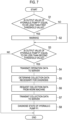
Fig. 7 , the characteristic processing operation of the present embodiment will be described for the case where the operation unit is the hydraulic pump P1. - First, when the engine is started and the
work machine 1 is driven, thefirst determination unit 32 included in thedata collection device 30 determines whether or not the output value of the hydraulic pump P1 which is the first operation data satisfies the first determination condition for determining whether or not to issue a warning. Here, whether or not to issue a warning is determined based on whether or not the output value of the hydraulic pump P1, which is the first operation data, is equal to or less than the first threshold value (S1). - When the output value of the hydraulic pump P1 is equal to or less than the first threshold value (Yes in S1), that is, when the first determination condition is satisfied, a warning is issued by, for example, lighting an unillustrated warning lamp provided at the driving seat of the
work machine 1 or sounding a buzzer (S2). Thus, the operator who operates thework machine 1 can visually and aurally know the abnormality of the hydraulic pump P1. - Subsequently, the
second determination unit 33 included in thedata collection device 30 determines whether or not the output value of the hydraulic pump P1 satisfies the second determination condition for determining whether or not to transmit the output value of the hydraulic pump P1 to theserver 40. Here, based on whether or not the output value of the hydraulic pump P1 is equal to or less than the second threshold value which is higher than the first threshold value, it is determined whether or not to transmit the output value of the hydraulic pump P1 to the server 40 (S3). When No is determined in Step S1, the process proceeds to Step S3 similarly, and it is determined whether or not the output value of the hydraulic pump P1 satisfies the second determination condition. - When it is determined that the output value of the hydraulic pump P1 should be transmitted to the
server 40 according to the determination result (Yes in S3), that is, when the second determination condition is satisfied, thefirst communication unit 34 included in thedata collection device 30 performs a processing of transmitting the output value of the hydraulic pump P1 to the server 40 (S4). When No is determined in Step S3, the processing operation ends. When there is no abnormality on thework machine 1 side, No is determined in Step S3 and the process ends. - Next, on the
server 40 side, based on the operation data transmitted from thework machine 1, thecollection determination unit 42 determines the collection data (pressure-sensor value, prime mover rotation speed, oil temperature) which is the second operation data necessary for diagnosis with reference to a predetermined table (S5). Then, based on the determination, thesecond communication unit 43 transmits a request signal for requesting the collection data (pressure-sensor value, prime mover rotation speed, oil temperature) to the data collection device 30 (S6). On thedata collection device 30 side, when thefirst communication unit 34 receives the request signal, thefirst communication unit 34 transmits the collection data (pressure-sensor value, prime mover rotation speed, oil temperature) requested by the request signal to the server 40 (S7). - Thus, the collection data necessary for diagnosis is determined based on the transmitted operation data, and the request signal for requesting the collection data is transmitted based on the determination, thereby the data to be collected by the
server 40 side can be narrowed down, and it is possible to suppress unnecessary transmission of a large amount of data from thedata collection device 30 side to theserver 40 side. - The
diagnosis unit 44 included in theserver 40 diagnoses the state of the hydraulic pump P1 based on the collection data (pressure-sensor value, prime mover rotation speed, oil temperature) sent from thedata collection device 30 side (S8). - Next, a case where the operation unit is a bearing will be described with reference to the flowchart of
Fig. 8 . - First, when the engine is started and the
work machine 1 is driven, thefirst determination unit 32 included in thedata collection device 30 determines whether or not a vibration value of the bearing which is the first operation data satisfies the first determination condition for determining whether or not to issue a warning. Here, whether or not to issue a warning is determined based on whether or not the vibration value of the bearing, which is the first operation data, is equal to or less than the first threshold value (S11). When the vibration value of the bearing is equal to or less than the first threshold value (Yes in S11), that is, when the first determination condition is satisfied, a warning is issued by, for example, lighting an unillustrated warning lamp provided at the driving seat of thework machine 1 or sounding a buzzer (S12). Thus, the operator who operates thework machine 1 can visually and aurally know the abnormality of the bearing. - Subsequently, the
second determination unit 33 included in thedata collection device 30 determines whether or not the vibration value of the bearing satisfies the second determination condition for determining whether or not to transmit the vibration value of the bearing to theserver 40. Here, based on whether or not the vibration value of the bearing is equal to or less than the second threshold value which is higher than the first threshold value, it is determined whether or not to transmit the vibration value of the bearing to the server 40 (S13). When No is determined in Step S11, the process proceeds to Step S13 similarly, and it is determined whether or not the vibration value of the bearing satisfies the second determination condition. - When it is determined that the vibration value of the bearing should be transmitted to the
server 40 according to the determination result (Yes in S13), that is, when the second determination condition is satisfied, thefirst communication unit 34 included in thedata collection device 30 performs a processing of transmitting the vibration value of the bearing to the server 40 (S14). When No is determined in Step S13, the processing operation ends. When there is no abnormality on thework machine 1 side, No is determined in Step S13 and the process ends. - Next, on the
server 40 side, based on the operation data transmitted from thework machine 1, thecollection determination unit 42 determines the collection data (the prime mover rotation speed, the value of the hour meter, the output of the hydraulic pump P1, the amount of lubricant oil, the acceleration of the bearing) which is the second operation data necessary for diagnosis with reference to a predetermined table (S15). Then, based on the determination, thesecond communication unit 43 transmits a request signal for requesting the collection data (the prime mover rotation speed, the value of the hour meter, the output of the hydraulic pump P1, the amount of lubricant oil, the acceleration of the bearing) to the data collection device 30 (S16). On thedata collection device 30 side, when the request signal is received, thefirst communication unit 34 transmits, to theserver 40, the collection data (the prime mover rotation speed, the value of the hour meter, the output of the hydraulic pump P1, the amount of lubricant oil, the acceleration of the bearing) requested by the request signal (S17). - The
diagnosis unit 44 included in theserver 40 diagnoses the state of the bearing based on the collection data (the prime mover rotation speed, the value of the hour meter, the output of the hydraulic pump P1, the amount of lubricant oil, the acceleration of the bearing) sent from thedata collection device 30 side (S18). - Next, a case where the operation unit is the
work lamp 91 will be described with reference to the flowchart ofFig. 9 . - First, when the engine is started and the
work machine 1 is driven, thefirst determination unit 32 included in thedata collection device 30 determines whether or not a voltage value of thework lamp 91 which is the first operation data satisfies the first determination condition for determining whether or not to issue a warning. Here, whether or not to issue a warning is determined based on whether or not the voltage value of thework lamp 91, which is the first operation data, is equal to or less than the first threshold value (S21). When the voltage value of thework lamp 91 is equal to or less than the first threshold value (Yes in S21), that is, when the first determination condition is satisfied, a warning is issued by, for example, lighting an unillustrated warning lamp provided at the driving seat of thework machine 1 or sounding a buzzer (S22). Thus, the operator who operates thework machine 1 can visually and aurally know the abnormality of thework lamp 91. - Subsequently, the
second determination unit 33 included in thedata collection device 30 determines whether or not the voltage value of thework lamp 91 satisfies the second determination condition for determining whether or not to transmit the voltage value of thework lamp 91 to theserver 40. Here, based on whether or not the voltage value of thework lamp 91 is equal to or less than the second threshold value which is higher than the first threshold value, it is determined whether or not to transmit the voltage value of thework lamp 91 to the server 40 (S23). When No is determined in Step S1, the process proceeds to Step S23 similarly, and it is determined whether or not the voltage value of thework lamp 91 satisfies the second determination condition. - When it is determined that the voltage value of the
work lamp 91 should be transmitted to theserver 40 according to the determination result (Yes in S23), that is, when the second determination condition is satisfied, thefirst communication unit 34 included in thedata collection device 30 performs a processing of transmitting the voltage value of thework lamp 91 to the server 40 (S24). When No is determined in Step S23, the processing operation ends. When there is no abnormality on thework machine 1 side, No is determined in Step S23 and the process ends. - Next, on the
server 40 side, based on the operation data transmitted from thework machine 1, thecollection determination unit 42 determines the collection data (the input voltage and the output voltage of thecontrol device 100, the battery voltage) which is the second operation data necessary for diagnosis with reference to a predetermined table (S25) . Then, based on the determination, thesecond communication unit 43 transmits a request signal for requesting the collection data (the input voltage and the output voltage of thecontrol device 100, the battery voltage) to the data collection device 30 (S26). - On the
data collection device 30 side, when the request signal is received, thefirst communication unit 34 transmits, to theserver 40, the collection data (the input voltage and the output voltage of thecontrol device 100, the battery voltage) requested by the request signal (S27) . - The
diagnosis unit 44 included in theserver 40 diagnoses the state of thework lamp 91 based on the collection data (the input voltage and the output voltage of thecontrol device 100, the battery voltage) sent from thedata collection device 30 side (S28). - In order to execute all the diagnoses as in the prior art, it is necessary to transmit a large amount of data from the
work machine 1 to theserver 40 from the beginning. In this regard, according to the present embodiment, it is possible to narrow down the data to be transmitted by once determining whether or not diagnosis is necessary on thework machine 1 side (Steps S3, S13, S23 described above). On theserver 40 side, the overall communication traffic can be reduced by requesting only the data necessary for diagnosis from thework machine 1 side (Steps S6, S16, S26 described above). - Although the backhoe is exemplified in the present embodiment, the application object of the present invention is not limited thereto, and the present invention can be applied to various work machines, for example, agricultural machines such as tractor, combined harvester, and rice transplanter, and construction machines such as compact track loader and skid steer loader.
- It should be understood that the embodiments disclosed herein are illustrative in all respects and are not restrictive. The scope of the present invention is defined not by the above description but by the claims, and is intended to include all modifications within the meaning and scope equivalent to the claims.
-
- 1
- Work machine
- 2
- Traveling device
- 3
- Revolving body
- 4
- Traveling body
- 5
- Dozer
- 9
- Driving seat
- 11
- Revolving bearing
- 12
- Revolving base
- 13
- Working device
- 14
- Cabin
- 16
- Support bracket
- 17
- Swing bracket
- 18
- Boom
- 19
- Arm
- 20
- Bucket
- 21
- Bucket cylinder
- 22
- Boom cylinder
- 23
- Arm cylinder
- 25
- Display device
- 30
- Data collection device
- 31
- Operation data output unit
- 32
- First determination unit
- 33
- Second determination unit
- 34
- First communication unit
- 40
- Server
- 41
- Diagnostic database
- 42
- Collection determination unit
- 43
- Second communication unit
- 44
- Diagnosis unit
- 90
- Control valve
- 91
- Work lamp
- 92
- Prime mover
- 100
- Control device
- 101
- Sensor
- 102
- Sensor
- 103
- Sensor
- 104
- Sensor
- 105
- Sensor
- 106
- Sensor
- M
- Traveling motor
- P1
- Hydraulic pump
Claims (5)
- A work machine information collection system in which a work machine having an operation unit and a server are communicably connected to each other, wherein
the work machine includes:an operation data output unit that outputs an operation data corresponding to an operation state of the operation unit;a determination unit that determines whether not the operation data satisfies a determination condition for determining whether or not to transmit the operation data output by the operation data output unit to the server; anda first communication unit that transmits the operation data to the server when the determination unit determines that the operation data satisfies the determination condition. - The work machine information collection system according to claim 1, whereinthe server includes:a collection determination unit that determines a collection data, which is an operation data to be collected for diagnosis of the work machine, based on the operation data transmitted from the first communication unit; anda second communication unit that transmits a request signal for requesting transmission of the collection data determined by the collection determination unit to the work machine, andthe first communication unit transmits the collection data corresponding to the request signal to the server when the request signal is received.
- The work machine information collection system according to claim 2, wherein
the server includes a diagnosis unit that diagnoses a state of the operation unit based on the collection data. - The work machine information collection system according to any one of claims 1 to 3, whereinthe work machine includes:a first determination unit that determines whether or not the operation data satisfies a first determination condition for determining whether or not to issue a warning; anda warning unit that issues a warning when the first determination unit determines that the operation data satisfies the first determination condition,the determination unit is a second determination unit,the determination condition is a second determination condition,the first determination condition includes a first threshold value for determining a state of a signal included in the operation data, andthe second determination condition includes a second threshold value that is for determining a state of a signal included in the operation data and is higher than the first threshold value.
- The work machine information collection system according to any one of claims 1 to 3, whereinthe work machine includes:a first determination unit that determines whether or not the operation data satisfies a first determination condition for determining whether or not to issue a warning; anda warning unit that issues a warning when the first determination unit determines that the operation data satisfies the first determination condition,the determination unit is a second determination unit,the determination condition is a second determination condition,the first determination condition includes a first threshold value for determining a state of a signal included in the operation data, andthe second determination condition includes a second threshold value that is for determining a state of a signal included in the operation data and is lower than the first threshold value.
Applications Claiming Priority (2)
| Application Number | Priority Date | Filing Date | Title |
|---|---|---|---|
| JP2021102237A JP7524136B2 (en) | 2021-06-21 | 2021-06-21 | Machinery information collection system |
| PCT/JP2022/016407 WO2022270117A1 (en) | 2021-06-21 | 2022-03-31 | Information collection system for work machine |
Publications (2)
| Publication Number | Publication Date |
|---|---|
| EP4361358A1 true EP4361358A1 (en) | 2024-05-01 |
| EP4361358A4 EP4361358A4 (en) | 2025-06-18 |
Family
ID=84545570
Family Applications (1)
| Application Number | Title | Priority Date | Filing Date |
|---|---|---|---|
| EP22828036.8A Pending EP4361358A4 (en) | 2021-06-21 | 2022-03-31 | Work machine information collection system |
Country Status (4)
| Country | Link |
|---|---|
| US (1) | US20240117610A1 (en) |
| EP (1) | EP4361358A4 (en) |
| JP (1) | JP7524136B2 (en) |
| WO (1) | WO2022270117A1 (en) |
Family Cites Families (11)
| Publication number | Priority date | Publication date | Assignee | Title |
|---|---|---|---|---|
| KR100523228B1 (en) * | 2001-05-08 | 2005-10-20 | 히다치 겡키 가부시키 가이샤 | Working machine, trouble diagnosis system of working machine, and maintenance system of working machine |
| US20090125196A1 (en) | 2007-11-14 | 2009-05-14 | Honeywell International, Inc. | Apparatus and method for monitoring the stability of a construction machine |
| US9637891B2 (en) * | 2013-03-08 | 2017-05-02 | Hitachi Construction Machinery Co., Ltd. | Management server for working machine and management method for working machine |
| JP2015045144A (en) | 2013-08-27 | 2015-03-12 | 住友建機株式会社 | Shovel |
| JP5758469B2 (en) * | 2013-10-25 | 2015-08-05 | 株式会社クボタ | Work machine operation status capture system |
| JP6417348B2 (en) | 2016-03-07 | 2018-11-07 | 日立建機株式会社 | Construction machine program rewriting device |
| JP6929026B2 (en) * | 2016-07-22 | 2021-09-01 | 株式会社クボタ | Work platform |
| US10328853B2 (en) * | 2017-01-16 | 2019-06-25 | Nio Usa, Inc. | Method and system for providing an escape route from a vehicle |
| JP6906209B2 (en) | 2018-09-26 | 2021-07-21 | 飛島建設株式会社 | Construction machine operation status management system and management method |
| JP2020149413A (en) | 2019-03-14 | 2020-09-17 | ヤンマーパワーテクノロジー株式会社 | Trouble diagnosing apparatus for hydraulic pump, construction machine comprising trouble diagnosing apparatus, trouble diagnosing method and trouble diagnosing program |
| US12203238B2 (en) | 2019-09-26 | 2025-01-21 | Hitachi Construction Machinery Co., Ltd. | Work machine configured to set a mask range in a field of vision over an antenna for which part of the work machine can become an obstacle when receiving positioning signals from satellites |
-
2021
- 2021-06-21 JP JP2021102237A patent/JP7524136B2/en active Active
-
2022
- 2022-03-31 WO PCT/JP2022/016407 patent/WO2022270117A1/en not_active Ceased
- 2022-03-31 EP EP22828036.8A patent/EP4361358A4/en active Pending
-
2023
- 2023-12-18 US US18/543,481 patent/US20240117610A1/en active Pending
Also Published As
| Publication number | Publication date |
|---|---|
| JP2023001479A (en) | 2023-01-06 |
| EP4361358A4 (en) | 2025-06-18 |
| WO2022270117A1 (en) | 2022-12-29 |
| US20240117610A1 (en) | 2024-04-11 |
| JP7524136B2 (en) | 2024-07-29 |
Similar Documents
| Publication | Publication Date | Title |
|---|---|---|
| CN105026214B (en) | Abnormal information control device for construction machinery | |
| US10657450B2 (en) | Systems and methods for machine diagnostics based on stored machine data and available machine telematic data | |
| JP4246039B2 (en) | Construction machine operation information management device | |
| US20140288675A1 (en) | Diagnostic Processing System, Onboard Terminal System, and Server | |
| JP2000055791A (en) | Method and apparatus for measuring equipment performance data of construction machinery | |
| CN105027015B (en) | Construction machine maintenance device | |
| JP4044763B2 (en) | Electronic control system for construction machinery | |
| EP1403437A1 (en) | Working machine, trouble diagnosis system of working machine, and maintenance system of working machine | |
| JP2000516374A (en) | Failure state prediction method and device | |
| EP3159519A2 (en) | Variable geometry turbocharger prognostics | |
| WO2001073224A1 (en) | Failure measure outputting method, output system, and output device | |
| CN111855209A (en) | Predictive diagnosis method and system for gear failure of drive axle main reducer | |
| JP2012160085A (en) | Maintenance method of construction machine and maintenance system | |
| WO2023102331A1 (en) | On-board machine component failure detection | |
| JP7589959B2 (en) | Construction machinery and construction machinery management device | |
| US20240117610A1 (en) | Work machine information collection system | |
| KR101983390B1 (en) | Fault diagnosis methods and apparatus of the wheel type excavators | |
| JPH1046631A (en) | Maintenance and management system for mobile work machines | |
| WO2022176331A1 (en) | Life prediction system for work machine | |
| JP2003030355A (en) | Maintenance system for working machine using two-way communication | |
| JP2005180225A (en) | Engine cooling water system fault diagnosis device for construction machinery | |
| JP4178101B2 (en) | Fault diagnosis device for hydraulic oil cooling system of construction machinery | |
| KR20220060126A (en) | Load voltage control system for construction machinery and method for controlling load voltage thereof | |
| US12110663B2 (en) | Shovel | |
| JP2024092434A (en) | Industrial machinery and communication systems for industrial machinery |
Legal Events
| Date | Code | Title | Description |
|---|---|---|---|
| STAA | Information on the status of an ep patent application or granted ep patent |
Free format text: STATUS: THE INTERNATIONAL PUBLICATION HAS BEEN MADE |
|
| PUAI | Public reference made under article 153(3) epc to a published international application that has entered the european phase |
Free format text: ORIGINAL CODE: 0009012 |
|
| STAA | Information on the status of an ep patent application or granted ep patent |
Free format text: STATUS: REQUEST FOR EXAMINATION WAS MADE |
|
| 17P | Request for examination filed |
Effective date: 20231215 |
|
| AK | Designated contracting states |
Kind code of ref document: A1 Designated state(s): AL AT BE BG CH CY CZ DE DK EE ES FI FR GB GR HR HU IE IS IT LI LT LU LV MC MK MT NL NO PL PT RO RS SE SI SK SM TR |
|
| DAV | Request for validation of the european patent (deleted) | ||
| DAX | Request for extension of the european patent (deleted) | ||
| A4 | Supplementary search report drawn up and despatched |
Effective date: 20250516 |
|
| RIC1 | Information provided on ipc code assigned before grant |
Ipc: E02F 9/26 20060101ALI20250512BHEP Ipc: E02F 9/20 20060101AFI20250512BHEP |